EP0683684B1 - Gastrostomy catheter system - Google Patents
Gastrostomy catheter system Download PDFInfo
- Publication number
- EP0683684B1 EP0683684B1 EP94905584A EP94905584A EP0683684B1 EP 0683684 B1 EP0683684 B1 EP 0683684B1 EP 94905584 A EP94905584 A EP 94905584A EP 94905584 A EP94905584 A EP 94905584A EP 0683684 B1 EP0683684 B1 EP 0683684B1
- Authority
- EP
- European Patent Office
- Prior art keywords
- catheter
- stomach
- dilatation
- gastrostomy
- patient
- Prior art date
- Legal status (The legal status is an assumption and is not a legal conclusion. Google has not performed a legal analysis and makes no representation as to the accuracy of the status listed.)
- Expired - Lifetime
Links
Images


Classifications
-
- A—HUMAN NECESSITIES
- A61—MEDICAL OR VETERINARY SCIENCE; HYGIENE
- A61J—CONTAINERS SPECIALLY ADAPTED FOR MEDICAL OR PHARMACEUTICAL PURPOSES; DEVICES OR METHODS SPECIALLY ADAPTED FOR BRINGING PHARMACEUTICAL PRODUCTS INTO PARTICULAR PHYSICAL OR ADMINISTERING FORMS; DEVICES FOR ADMINISTERING FOOD OR MEDICINES ORALLY; BABY COMFORTERS; DEVICES FOR RECEIVING SPITTLE
- A61J15/00—Feeding-tubes for therapeutic purposes
- A61J15/0015—Gastrostomy feeding-tubes
-
- A—HUMAN NECESSITIES
- A61—MEDICAL OR VETERINARY SCIENCE; HYGIENE
- A61J—CONTAINERS SPECIALLY ADAPTED FOR MEDICAL OR PHARMACEUTICAL PURPOSES; DEVICES OR METHODS SPECIALLY ADAPTED FOR BRINGING PHARMACEUTICAL PRODUCTS INTO PARTICULAR PHYSICAL OR ADMINISTERING FORMS; DEVICES FOR ADMINISTERING FOOD OR MEDICINES ORALLY; BABY COMFORTERS; DEVICES FOR RECEIVING SPITTLE
- A61J15/00—Feeding-tubes for therapeutic purposes
- A61J15/0026—Parts, details or accessories for feeding-tubes
- A61J15/003—Means for fixing the tube inside the body, e.g. balloons, retaining means
- A61J15/0034—Retainers adjacent to a body opening to prevent that the tube slips through, e.g. bolsters
- A61J15/0038—Retainers adjacent to a body opening to prevent that the tube slips through, e.g. bolsters expandable, e.g. umbrella type
- A61J15/0042—Retainers adjacent to a body opening to prevent that the tube slips through, e.g. bolsters expandable, e.g. umbrella type inflatable
-
- A—HUMAN NECESSITIES
- A61—MEDICAL OR VETERINARY SCIENCE; HYGIENE
- A61J—CONTAINERS SPECIALLY ADAPTED FOR MEDICAL OR PHARMACEUTICAL PURPOSES; DEVICES OR METHODS SPECIALLY ADAPTED FOR BRINGING PHARMACEUTICAL PRODUCTS INTO PARTICULAR PHYSICAL OR ADMINISTERING FORMS; DEVICES FOR ADMINISTERING FOOD OR MEDICINES ORALLY; BABY COMFORTERS; DEVICES FOR RECEIVING SPITTLE
- A61J15/00—Feeding-tubes for therapeutic purposes
- A61J15/0026—Parts, details or accessories for feeding-tubes
- A61J15/0073—Multi-lumen tubes
-
- A—HUMAN NECESSITIES
- A61—MEDICAL OR VETERINARY SCIENCE; HYGIENE
- A61M—DEVICES FOR INTRODUCING MEDIA INTO, OR ONTO, THE BODY; DEVICES FOR TRANSDUCING BODY MEDIA OR FOR TAKING MEDIA FROM THE BODY; DEVICES FOR PRODUCING OR ENDING SLEEP OR STUPOR
- A61M25/00—Catheters; Hollow probes
- A61M25/01—Introducing, guiding, advancing, emplacing or holding catheters
- A61M25/02—Holding devices, e.g. on the body
-
- A—HUMAN NECESSITIES
- A61—MEDICAL OR VETERINARY SCIENCE; HYGIENE
- A61J—CONTAINERS SPECIALLY ADAPTED FOR MEDICAL OR PHARMACEUTICAL PURPOSES; DEVICES OR METHODS SPECIALLY ADAPTED FOR BRINGING PHARMACEUTICAL PRODUCTS INTO PARTICULAR PHYSICAL OR ADMINISTERING FORMS; DEVICES FOR ADMINISTERING FOOD OR MEDICINES ORALLY; BABY COMFORTERS; DEVICES FOR RECEIVING SPITTLE
- A61J15/00—Feeding-tubes for therapeutic purposes
- A61J15/0003—Nasal or oral feeding-tubes, e.g. tube entering body through nose or mouth
- A61J15/0007—Nasal or oral feeding-tubes, e.g. tube entering body through nose or mouth inserted by using a guide-wire
-
- A—HUMAN NECESSITIES
- A61—MEDICAL OR VETERINARY SCIENCE; HYGIENE
- A61J—CONTAINERS SPECIALLY ADAPTED FOR MEDICAL OR PHARMACEUTICAL PURPOSES; DEVICES OR METHODS SPECIALLY ADAPTED FOR BRINGING PHARMACEUTICAL PRODUCTS INTO PARTICULAR PHYSICAL OR ADMINISTERING FORMS; DEVICES FOR ADMINISTERING FOOD OR MEDICINES ORALLY; BABY COMFORTERS; DEVICES FOR RECEIVING SPITTLE
- A61J15/00—Feeding-tubes for therapeutic purposes
- A61J15/0026—Parts, details or accessories for feeding-tubes
- A61J15/0053—Means for fixing the tube outside of the body, e.g. by a special shape, by fixing it to the skin
- A61J15/0061—Means for fixing the tube outside of the body, e.g. by a special shape, by fixing it to the skin fixing at an intermediate position on the tube, i.e. tube protruding the fixing means
-
- A—HUMAN NECESSITIES
- A61—MEDICAL OR VETERINARY SCIENCE; HYGIENE
- A61M—DEVICES FOR INTRODUCING MEDIA INTO, OR ONTO, THE BODY; DEVICES FOR TRANSDUCING BODY MEDIA OR FOR TAKING MEDIA FROM THE BODY; DEVICES FOR PRODUCING OR ENDING SLEEP OR STUPOR
- A61M25/00—Catheters; Hollow probes
- A61M25/01—Introducing, guiding, advancing, emplacing or holding catheters
- A61M25/02—Holding devices, e.g. on the body
- A61M2025/0213—Holding devices, e.g. on the body where the catheter is attached by means specifically adapted to a part of the human body
- A61M2025/0233—Holding devices, e.g. on the body where the catheter is attached by means specifically adapted to a part of the human body specifically adapted for attaching to a body wall by means which are on both sides of the wall, e.g. for attaching to an abdominal wall
-
- A—HUMAN NECESSITIES
- A61—MEDICAL OR VETERINARY SCIENCE; HYGIENE
- A61M—DEVICES FOR INTRODUCING MEDIA INTO, OR ONTO, THE BODY; DEVICES FOR TRANSDUCING BODY MEDIA OR FOR TAKING MEDIA FROM THE BODY; DEVICES FOR PRODUCING OR ENDING SLEEP OR STUPOR
- A61M25/00—Catheters; Hollow probes
- A61M25/01—Introducing, guiding, advancing, emplacing or holding catheters
- A61M25/02—Holding devices, e.g. on the body
- A61M2025/0266—Holding devices, e.g. on the body using pads, patches, tapes or the like
- A61M2025/0273—Holding devices, e.g. on the body using pads, patches, tapes or the like having slits to place the pad around a catheter puncturing site
Definitions
- This invention generally relates to enteric feeding tubes and particularly to enteric feeding tubes which are inserted into the interior of a patient's stomach through the patient's abdominal and stomach walls.
- a gastrostomy tube into a patient's stomach for enteral feeding and medication.
- One of such techniques involves making an opening in portions of the stomach wall and the abdominal wall and passing the gastrostomy tube through the opening until its distal end is well disposed within the patient's stomach.
- the stomach wall is secured to the abdominal wall by means of a plurality of T-fasteners.
- the opening in the abdominal and stomach walls may be formed by means of a Seldinger technique wherein a relatively large needle is inserted through the walls into the stomach, a guidewire or a peel-away introducer sheath, such as shown in U.S. Patent 4,166,469 is inserted through the needle forming the opening and then the needle is removed.
- the opening is usually enlarged to allow for the passage of the gastrostomy tube by advancing a series of dilators of increasing diameters through the opening.
- stomach wall is secured to the abdominal wall by T-fasteners, sometimes the forces applied to the stomach wall by the advancing dilators or gastrostomy tube are sufficiently high to cause the stomach wall to tear away from the T-fasteners which secure the stomach wall to the abdominal wall. If the stomach wall is not secured to the abdominal wall, the stomach wall tends to be pushed away by the dilators, i.e. forming a tent-like indentation in the stomach wall.
- the present invention provides a gastrostomy catheter system according to claim 1. Further aspects of the invention are provided according to the dependent claims.
- This invention is directed to a catheter system for placing a gastrostomy catheter into the interior of a patient's stomach through the secured walls of the patient's stomach and abdomen.
- the system of the invention includes a dilatation catheter having an elongated catheter shaft with an expandable dilatation member, e.g. an inflatable balloon on a distal section of the catheter shaft. If an inflatable member is provided, the catheter has an inflation lumen which is in fluid communication with the inflatable member. An adapter is provided on the proximal end of the catheter shaft which is adapted to direct inflation fluid from a source to the inflation lumen in the catheter shaft.
- the dilatation catheter has an outer diameter which is small enough to be slidable within an inner lumen of a gastrostomy catheter and it is long enough so that the proximal end of the dilatation catheter extends out of the proximal end of the gastrostomy catheter while the dilatation balloon on the distal section of the dilatation catheter extends completely out of the distal end of the gastrostomy catheter.
- the adapter on the proximal end of the dilatation catheter is preferably removable to allow the gastrostomy catheter to be more easily loaded onto the proximal end of the dilatation catheter.
- the dilatation catheter may be provided with a guidewire lumen which extends to a guidewire port in the distal end of the catheter to facilitate guiding the catheter through over a guidewire the passageway formed in the abdominal and gastric walls to be dilated.
- the balloon of the dilatation catheter is formed of a polymer material which inflates to a desired diameter but which does not expand significantly beyond that the desired diameter for dilatating a passageway for the gastrostomy catheter, even when the inflation pressure is increased significantly beyond the pressure which expands the balloon to the desired diameter, i.e. the balloon is relatively inelastic or noncompliant at the elevated pressures.
- Suitable balloon materials include inelastic polymers such as polyethylene, polyethylene terephthalate, polyvinyl chloride and polyolephinic ionomers such as Surlyn® .
- the gastrostomy catheter generally has a catheter shaft with a first lumen extending from the proximal end to the distal end of the catheter shaft which is adapted to direct fluis from the proximal end of the catheter, out the port in the distal end into the interior of the patient's stomach.
- the gastrostomy catheter is also provided with an internal retention means which prevents the removal of the catheter through the passageway extending through the abdominal and gastric walls.
- the internal retention means is an expandable member such as a balloon or a mechanical device as described in U.S Patent 4,666,433 and U.S. Patent 5,073,166. Both of these patents have been assigned to the present assignee Medical Innovations Corp. of Milpitas, CA.
- a second lumen extends within the catheter shaft from the proximal end of the gastrostomy catheter to the interior of the balloon to provide fluid for the latter's inflation after the distal extremity of the gastrostomy catheter is properly disposed within the patient's stomach.
- the dilatation catheter which is adapted to be disposed within the fluid delivery lumen of the gastrostomy catheter, is advanced into the passageway formed through the abdominal and stomach walls until the dilatation balloon extends along the entire length of the passageway and, once properly positioned within the passageway, the balloon is inflated to dilate the passageway.
- the dilatation is preferably performed under fluoroscopic observation. During the initial stage of the balloon inflation, a portion of the dilatation balloon within the passageway, particularly within the fascia of the abdominal wall, does not expand completely, thus forming a waist which is readily seen fluoroscopically if the balloon is inflated with radiopaque fluid.
- the inflation pressure within the dilatation balloon is increased until the diameter of the inflated balloon is essentially the same along its length, i.e. the waist disappears. More than one inflation may be required for complete dilatation.
- the gastrostomy catheter may be advanced over the dilatation catheter until the distal end of the gastrostomy catheter is disposed well within the interior of the patient's stomach.
- the gastrostomy catheter is mounted over the proximal end of the dilatation catheter onto the shaft thereof before the dilatation catheter is inserted into the passageway in the abdominal wall and the gastric wall so that when the passageway is dilated, the dilatation balloon can be deflated and the gastrostomy catheter immediately advanced thereover.
- the dilatation catheter may then be removed.
- the balloon on the distal end of the gastrostomy catheter within the stomach is inflated and the catheter withdrawn through the passageway in the abdominal and stomach walls until the inflated balloon is urged snugly against the interior of the stomach wall.
- a sealing ring which is frictionally mounted on the shaft of the gastrostomy catheter is then advanced distally on the shaft until it is pressed against the exterior of the abdominal wall. This procedure seals the passageway.
- the present invention provides a catheter system which facilitates the placement of a gastrostomy catheter within a patient's stomach.
- the inflation of the dilatation balloon on the dilatation catheter applies essentially only radial pressure against the passageway through the patient's abdominal and stomach walls to expand the passageway sufficiently to allow for the passage therethrough of a gastrostomy tube.
- the expansion of the passageway and the passage of the gastrostomy catheter therethrough applies little or no shear forces to the stomach wall which can cause damage, e.g. tearing the stomach lining away from T-fasteners which secure the stomach wall to the abdominal wall.
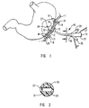
- Fig 1 is an elevational view, partially in section, of a gastrostomy catheter disposed through a passageway in a patient's abdominal and stomach walls.
- Fig. 2 is a transverse cross-sectional view of the catheter shown in Fig. 1 taken along the lines 2-2.
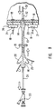
- Fig. 3 is an elevational view of a dilatation catheter which embodies features of the present invention.
- Fig. 4 is a transverse cross-sectional view of the dilatation catheter shown in Fig. 3 taken along the lines 4-4.
- Fig. 5 is an enlarged cross-sectional view of a distal portion of the catheter shown in Fig. 3.
- Fig. 6 is an elevational view of an assembly with the dilatation catheter shown in Fig. 3 disposed within an inner lumen of a gastrostomy catheter such as illustrated in Fig. 1.
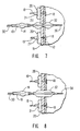
- Figs. 7-9 illustrate the insertion of the catheter assembly shown in Fig. 5 into a patient's stomach.
- Figs. 1 and 2 depict a gastrostomy catheter 10 extending through a patient's abdominal wall 11 and stomach wall 12.
- the gastrostomy catheter 10 has an elongated catheter shaft 13 with an internal retention member, inflatable balloon 14 on a distal portion thereof, an external retention ring 15 fictionally mounted onto the exterior of the shaft 13 and a multiarm adapter 16 on the proximal end of the catheter shaft.
- the balloon 14 is inflated and the catheter 10 is withdrawn through the passageway 17 until the balloon is urged against the inside of the stomach wall 12.
- the external retention ring 15 is advanced over the shaft 13 and is pressed against the exterior of the patient's abdominal wall 11 to secure the gastrostomy catheter within the abdominal and stomach walls.
- the abdominal wall 11 and the stomach wall 12 are secured together at several locations by means of T-fasteners 18 which are disposed within the interior of the stomach.
- the sutures 19 may be knotted several times or crimps (not shown) may be employed to secure the buttons 21 against each of the pledgets 20 with sufficient pressure to hold the stomach against the wall of the abdomen.
- the multiarm adapter 16 has an arm 22 which is adapted to receive nutrients and the like in fluid form from a source such as a syringe (not shown) and deliver such fluids through an inner lumen 23 within the catheter shaft 13 and out a port 24 in the distal end thereof to the interior of the patient's stomach.
- Arm 25 is adapted to receive medication in fluid form and deliver the fluids through the lumen 26 to a port 27 in the distal end of the catheter shaft 13.
- lumens 23 and 26 may be a single lumen.
- Arm 28 is adapted to receive an inflation device (not shown) and is in fluid communication with the balloon 14 through lumen 29.
- the gastrostomy catheter 10 is inserted through the passageway 17 in abdominal and stomach walls 11 and 12 with the aid of a dilatation catheter 30 as shown in Figs. 7-9.
- the dilatation catheter 30, as best shown in Figs. 3-5, has an elongated shaft 31, a dilatation balloon 32 on a distal section thereof and a removable multiarm adapter 33, which is secured to the proximal end of the catheter shaft 31.
- the catheter shaft 31 has an inflation lumen 34 which extends therein from the proximal end of the catheter shaft to the interior of the balloon 32 and a guidewire receiving lumen 35 which extends from the proximal end to the distal end of the catheter shaft.
- the balloon member 32 is preferably formed of material which allows the balloon to be inflated to a desired size but which does not exhibit significant expansion beyond the desired size upon increased pressures e.g. it is relatively inelastic or noncompliant at its inflated diameter.
- Fig. 6 illustrates an assembly of the gastrostomy catheter 10 and the dilatation catheter 30 ready for insertion through passageway 17, with the dilatation catheter disposed within an inner lumen 23 of the gastrostomy catheter.
- the inner lumen 23 of the gastrostomy catheter 10 is lubricated with a suitable sterile lubricant, e.g. mineral oil, and then the proximal end of the dilatation catheter 30, with the adapter 33 removed, is inserted into the inner lumen 23 of the gastrostomy catheter through its distal end and advanced therein until the proximal end of the dilatation catheter extends out the arm 22 of the gastrostomy catheter.
- a suitable sterile lubricant e.g. mineral oil
- the dilatation balloon 30 should extend completely out of the port 24 in the distal end of the gastrostomy catheter 10 to ensure the complete inflation thereof.
- the adapter 33 may then be mounted onto the proximal end of the catheter shaft 31 and secured thereto by tightening collar 37.
- the patient's stomach is filled with air to displace the overlying bowel gas and the site is selected fluoroscopically to avoid the patient's liver, small bowel and colon.
- the three or four sites for T-fastener placement are marked on the exterior of the abdomen about the region chosen for gastrostomy catheter placement in the shape of an equilateral triangle (for three T-fastener sites) or a square (for four T-fastener sites).
- the skin, subcutaneous tissues and peritoneal lining are liberally anesthetized with a 1% procaine (Xylocaine® ) and a nick is made through the skin at each of the T-fastener sites.
- a procaine Xylocaine®
- An introducer needle e.g. 17 gage preloaded with a T-fastener 18 is advanced through the anterior abdominal wall 11 through the nicks at a T-fastener site and then given a rapid thrust of 2-5 cm to ensure that the introducer needle passes completely through the gastric wall 12 and into the gastric lumen.
- the gastric wall tends to form an inwardly projecting tent-like structure when the distal end of the needle is pressed against the exterior thereof without penetration, but by providing a quick thrust, the sharp distal tip of the needle easily passes through the gastric wall.
- Air is aspirated with a syringe attached to the introducer needle to confirm that the distal tip of the needle is within the interior of the stomach.
- the syringe is removed from the needle and a rod is passed through the needle from its proximal end to push T-fastener 18 disposed within the needle lumen into the interior of the stomach.
- the suture 19 attached to the T-fastener extends out of the abdominal wall 11.
- the introducer needle is then removed and the suture secured to the T-fastener is withdrawn pulling the anterior gastric wall and omentum snugly against the anterior abdominal wall.
- the pledget 20 and the button 21, through which the suture 19 is threaded, are slid along the suture and urged against the abdominal surface and then the suture 19 is tied in several knots (5 or more is preferred) to hold the button 21 against the pledget 20 with sufficient pressure to hold the T-fastener 18 snugly but not tightly against the stomach wall 12 as shown in Fig. 1.
- a suitable T-fastener system is the Brown-Mueller T-fastener set available from Meditech (Boston Scientific Corp of Watertown, MA). Other suitable systems are commercially available.
- the site for inserting the gastrostomy catheter 10 into the patient's stomach is prepared in essentially the same manner as the sites for inserting the T-fasteners 18.
- the skin, the subcutaneous tissues and the peritoneum are liberally anesthetized with a 1% procaine and then a small incision, e.g. 10-12 mm in length, is made parallel to the major branches of the superior epigastric arteries.
- An introducer needle e.g. 18 gage puncture needle
- a syringe is attached to the needle to aspirate air to ensure proper placement within the interior of the stomach.
- a suitable guidewire 36 e.g.
- a 0.038" J-tip guidewire is passed through the lumen of the needle into the interior of the stomach and allowed to loop liberally within the stomach to protect against accidental dislodgement of the guidewire.
- the introducer needle is then withdrawn from the abdominal and gastric walls 11 and 12 and the passageway or track 17 formed in the abdominal and stomach walls by the introducer needle is predilated by passing a plurality of catheter type dilators, e.g. first an 8 french catheter and then a 12 french catheter, over the in-place guidewire 36 to facilitate the advancement of the dilatation catheter 30 through the track 17.
- the gastrostomy catheter 10 is preloaded onto the shaft 31 of the dilatation catheter 30 by removing the adapter 33 on the dilatation catheter and advancing the gastrostomy catheter over the dilatation catheter (or vice versa) until the dilatation balloon 32 extends completely out of the distal end of the gastrostomy catheter and then the assembled catheters are advanced over the in-place guidewire 36 until the balloon 32 on the dilatation catheter 30 extends through the passageway 17 across both the abdominal wall 11 and the stomach wall 12.
- the adapter 33 is remounted onto the proximal end of the dilatation catheter 30 and then by passing the shaft 31 into the distal end of the adapter and tightening the cap 32 onto the distal of the adapter (see Fig.
- dilatation balloon 32 is inflated to dilatation pressures (e.g. 12-15 atm.) to dilate the track 17 sufficiently to allow the gastrostomy catheter 10 to pass easily through the passageway without applying stress to the stomach wall which might tear the wall away from the T-fastener 18.
- the balloon 32 is preferably inflated with radiopaque liquid so that the expansion of the balloon can be monitored fluoroscopically. In the initial stages of the dilatation as shown in Fig. 7, the portion of the balloon 32 within the fascia of the abdominal wall does not expand as much as the rest of the tissue through which the balloon extends and it forms a waist 37 which is readily observed fluoroscopically.
- the balloon 32 is inflated one or more times to its dilatation diameter within the passageway 17 until the waist 37 disappears as shown in Fig. 8. It is important that the passageway 17 be properly dilated so that there is no excessive force applied to the stomach wall when pushing of the gastrostomy catheter 10 through the passageway which might cause the T-fasteners to tear through the wall of the stomach.
- the passageway 17 should be expanded to at least about 1 cm to ensure minimum forces on the stomach wall 12.
- the balloon 32 on the dilatation catheter 30 is deflated and the gastrostomy catheter 10 is advanced over the dilatation catheter 30 as shown in Fig. 9 until the balloon 14 on the gastrostomy catheter is well within the interior of the stomach.
- the balloon 14 is inflated to the desired size and then the gastrostomy catheter 10 is withdrawn through the passageway 17 until the inflated balloon 14 is pulled snugly against the stomach wall 12.
- the dilatation catheter 30 and the guidewire 36 are removed after confirming that the balloon 14 is properly positioned within the stomach.
- the external retention ring 15 on the shaft 13 of the catheter 10 is pushed against the exterior of the abdominal wall 11 as depicted in Fig. 1 to effectively secure the gastrostomy 10 within the stomach.
- the dilatation catheter 30 typically has an overall length of about 12 to about 40 inches (30.4-102 cm) and a shaft diameter of about 3-8 French (1-2.6 mm) to facilitate passages through inner lumen 23 of gastrostomy catheter 10.
- the balloon has an inflated diameter of about 5 to about 15 mm and a length of about 1 to about 15 cm, preferably about 8-12 cm.
- the dimensions of the dilatation catheter depend to a large extent upon the dimensions of the gastrostomy catheter to be used.
- the overall length of the dilatation catheter 30 must be great enough so that proximal end extends out the proximal end of the gastrostomy catheter and the balloon 32 extends completely out the distal end of the gastrostomy catheter.
- the gastrostomy catheter 10 and the dilatation catheter 30 can be conveniently packaged together as a kit with the catheters either separate from one another or with the dilatation catheter 30 slidably disposed within the inner lumen 23 of the gastrostomy catheter as shown in Fig. 6. Ideally, the assembly of the gastrostomy catheter 10 and the dilatation catheter 30 are ready for mounting on a guidewire. Additional items which may be included in the kit include a guidewire, T-fasteners with attached sutures, suitable pledgets and buttons, an inflation device such as syringe, an introducer needle and the like. Other items used in the procedure of inserting and fixing the gastrostomy catheter 10 may also be included in the kit such as a vial of anesthetic, e.g. 1% procaine and a needle and syringe to use the anesthetic.
- anesthetic e.g. 1% procaine and a needle and syringe to use the anesthetic.
- the enteric gastrostomy catheters may also provide jejunal access such as with the MIC Gastro-Enteric Tube and the MIC Jejunal Tube which are available from the assignee of the present application, Medical Innovations Corporation of Milpitas, California.
- the catheter shaft of the gastrostomy catheter is depicted in Fig. 2 as extruded or other wise formed into a unitary mass.
- the shaft can be formed from individual tubular elements which have been heat fused together.
Abstract
Description
- This invention generally relates to enteric feeding tubes and particularly to enteric feeding tubes which are inserted into the interior of a patient's stomach through the patient's abdominal and stomach walls.
- There are a number of patient's who are unable to chew or swallow for relatively long periods of time. Examples of such patient's include those who are neurologically impaired, e.g. stroke, those who have had traumatic injury to their head or neck areas, e.g. a broken jaw, and those who have an obstruction in their esophagus, e.g. cancer. In these instances, it is common practice to insert an enteric feeding tube, sometimes called a gastrostomy tube or catheter, through the patient's abdominal and gastric walls into the interior of the patient's stomach in order to feed the patient nutrients, medicaments and the like through the gastrostomy tube until such time of the patient can chew and swallow on his or her own.
- There are several well known techniques for inserting a gastrostomy tube into a patient's stomach for enteral feeding and medication. One of such techniques involves making an opening in portions of the stomach wall and the abdominal wall and passing the gastrostomy tube through the opening until its distal end is well disposed within the patient's stomach. Very frequently in this technique the stomach wall is secured to the abdominal wall by means of a plurality of T-fasteners. The opening in the abdominal and stomach walls may be formed by means of a Seldinger technique wherein a relatively large needle is inserted through the walls into the stomach, a guidewire or a peel-away introducer sheath, such as shown in U.S. Patent 4,166,469 is inserted through the needle forming the opening and then the needle is removed. The opening is usually enlarged to allow for the passage of the gastrostomy tube by advancing a series of dilators of increasing diameters through the opening.
- However, it is not uncommon to experience some difficulty in advancing the dilators and a gastrostomy tube through the opening formed in the patient's abdominal and stomach walls. If the stomach wall is secured to the abdominal wall by T-fasteners, sometimes the forces applied to the stomach wall by the advancing dilators or gastrostomy tube are sufficiently high to cause the stomach wall to tear away from the T-fasteners which secure the stomach wall to the abdominal wall. If the stomach wall is not secured to the abdominal wall, the stomach wall tends to be pushed away by the dilators, i.e. forming a tent-like indentation in the stomach wall.
- What has been needed is a system which can easily advance a gastrostomy tube through the patient's abdominal wall and stomach wall so that the distal end thereof is properly disposed within the patient's stomach without damage to the patient's stomach wall. These and other needs are satisfied by the present invention.
- The present invention provides a gastrostomy catheter system according to claim 1. Further aspects of the invention are provided according to the dependent claims.
- This invention is directed to a catheter system for placing a gastrostomy catheter into the interior of a patient's stomach through the secured walls of the patient's stomach and abdomen.
- The system of the invention includes a dilatation catheter having an elongated catheter shaft with an expandable dilatation member, e.g. an inflatable balloon on a distal section of the catheter shaft. If an inflatable member is provided, the catheter has an inflation lumen which is in fluid communication with the inflatable member. An adapter is provided on the proximal end of the catheter shaft which is adapted to direct inflation fluid from a source to the inflation lumen in the catheter shaft. The dilatation catheter has an outer diameter which is small enough to be slidable within an inner lumen of a gastrostomy catheter and it is long enough so that the proximal end of the dilatation catheter extends out of the proximal end of the gastrostomy catheter while the dilatation balloon on the distal section of the dilatation catheter extends completely out of the distal end of the gastrostomy catheter. The adapter on the proximal end of the dilatation catheter is preferably removable to allow the gastrostomy catheter to be more easily loaded onto the proximal end of the dilatation catheter. The dilatation catheter may be provided with a guidewire lumen which extends to a guidewire port in the distal end of the catheter to facilitate guiding the catheter through over a guidewire the passageway formed in the abdominal and gastric walls to be dilated.
- The balloon of the dilatation catheter is formed of a polymer material which inflates to a desired diameter but which does not expand significantly beyond that the desired diameter for dilatating a passageway for the gastrostomy catheter, even when the inflation pressure is increased significantly beyond the pressure which expands the balloon to the desired diameter, i.e. the balloon is relatively inelastic or noncompliant at the elevated pressures. Suitable balloon materials include inelastic polymers such as polyethylene, polyethylene terephthalate, polyvinyl chloride and polyolephinic ionomers such as Surlyn® .
- The gastrostomy catheter generally has a catheter shaft with a first lumen extending from the proximal end to the distal end of the catheter shaft which is adapted to direct fluis from the proximal end of the catheter, out the port in the distal end into the interior of the patient's stomach. The gastrostomy catheter is also provided with an internal retention means which prevents the removal of the catheter through the passageway extending through the abdominal and gastric walls. Preferable, the internal retention means is an expandable member such as a balloon or a mechanical device as described in U.S Patent 4,666,433 and U.S. Patent 5,073,166. Both of these patents have been assigned to the present assignee Medical Innovations Corp. of Milpitas, CA. With a catheter having an inflatable member, a second lumen extends within the catheter shaft from the proximal end of the gastrostomy catheter to the interior of the balloon to provide fluid for the latter's inflation after the distal extremity of the gastrostomy catheter is properly disposed within the patient's stomach.
- Presently preferred embodiments of the gastrostomy catheter are described in U.S. Patent 4,685,592, U.S. Patent 4,701,163 and U.S. Patent 4,798,592. As described in these patents, the balloon on the distal section of the gastrostomy catheter is inflated while it is disposed within the interior of the stomach and then the catheter is tugged to pull the inflated balloon against the interior of the stomach wall. An exterior retention ring, which is frictionally mounted onto the shaft of the gastrostomy catheter, is then urged along the catheter shaft until it presses against the exterior surface of the abdominal wall to ensure that the gastrostomy catheter is secured and can not move distally.
- The dilatation catheter, which is adapted to be disposed within the fluid delivery lumen of the gastrostomy catheter, is advanced into the passageway formed through the abdominal and stomach walls until the dilatation balloon extends along the entire length of the passageway and, once properly positioned within the passageway, the balloon is inflated to dilate the passageway. The dilatation is preferably performed under fluoroscopic observation. During the initial stage of the balloon inflation, a portion of the dilatation balloon within the passageway, particularly within the fascia of the abdominal wall, does not expand completely, thus forming a waist which is readily seen fluoroscopically if the balloon is inflated with radiopaque fluid. The inflation pressure within the dilatation balloon is increased until the diameter of the inflated balloon is essentially the same along its length, i.e. the waist disappears. More than one inflation may be required for complete dilatation. After the dilatation balloon is deflated, the gastrostomy catheter may be advanced over the dilatation catheter until the distal end of the gastrostomy catheter is disposed well within the interior of the patient's stomach. Preferably, the gastrostomy catheter is mounted over the proximal end of the dilatation catheter onto the shaft thereof before the dilatation catheter is inserted into the passageway in the abdominal wall and the gastric wall so that when the passageway is dilated, the dilatation balloon can be deflated and the gastrostomy catheter immediately advanced thereover.
- Once the distal end of the gastrostomy is disposed well within the interior of the stomach, the dilatation catheter may then be removed. To secure the distal end of the gastrostomy catheter the balloon on the distal end of the gastrostomy catheter within the stomach is inflated and the catheter withdrawn through the passageway in the abdominal and stomach walls until the inflated balloon is urged snugly against the interior of the stomach wall. A sealing ring which is frictionally mounted on the shaft of the gastrostomy catheter is then advanced distally on the shaft until it is pressed against the exterior of the abdominal wall. This procedure seals the passageway.
- The present invention provides a catheter system which facilitates the placement of a gastrostomy catheter within a patient's stomach. The inflation of the dilatation balloon on the dilatation catheter applies essentially only radial pressure against the passageway through the patient's abdominal and stomach walls to expand the passageway sufficiently to allow for the passage therethrough of a gastrostomy tube. However, the expansion of the passageway and the passage of the gastrostomy catheter therethrough applies little or no shear forces to the stomach wall which can cause damage, e.g. tearing the stomach lining away from T-fasteners which secure the stomach wall to the abdominal wall. These and other advantages of the invention will become more apparent from the following detailed description of the invention, when taken in conjunction with the accompanying exemplary drawings.
- Fig 1 is an elevational view, partially in section, of a gastrostomy catheter disposed through a passageway in a patient's abdominal and stomach walls.
- Fig. 2 is a transverse cross-sectional view of the catheter shown in Fig. 1 taken along the lines 2-2.
- Fig. 3 is an elevational view of a dilatation catheter which embodies features of the present invention.
- Fig. 4 is a transverse cross-sectional view of the dilatation catheter shown in Fig. 3 taken along the lines 4-4.
- Fig. 5 is an enlarged cross-sectional view of a distal portion of the catheter shown in Fig. 3.
- Fig. 6 is an elevational view of an assembly with the dilatation catheter shown in Fig. 3 disposed within an inner lumen of a gastrostomy catheter such as illustrated in Fig. 1.
- Figs. 7-9 illustrate the insertion of the catheter assembly shown in Fig. 5 into a patient's stomach.
- Figs. 1 and 2 depict a
gastrostomy catheter 10 extending through a patient's abdominal wall 11 andstomach wall 12. Thegastrostomy catheter 10 has anelongated catheter shaft 13 with an internal retention member,inflatable balloon 14 on a distal portion thereof, anexternal retention ring 15 fictionally mounted onto the exterior of theshaft 13 and amultiarm adapter 16 on the proximal end of the catheter shaft. As shown, theballoon 14 is inflated and thecatheter 10 is withdrawn through thepassageway 17 until the balloon is urged against the inside of thestomach wall 12. Theexternal retention ring 15 is advanced over theshaft 13 and is pressed against the exterior of the patient's abdominal wall 11 to secure the gastrostomy catheter within the abdominal and stomach walls. The abdominal wall 11 and thestomach wall 12 are secured together at several locations by means of T-fasteners 18 which are disposed within the interior of the stomach.Sutures 19, which are secured by one end to each of the T-fasteners, pass through the abdominal andgastric walls 11 and 12, a padded retention element, such as acotton pledget 20 shown, and a nylon washer orbutton 21 disposed on the exterior of the abdominal wall 11. Thesutures 19 may be knotted several times or crimps (not shown) may be employed to secure thebuttons 21 against each of thepledgets 20 with sufficient pressure to hold the stomach against the wall of the abdomen. - The
multiarm adapter 16 has anarm 22 which is adapted to receive nutrients and the like in fluid form from a source such as a syringe (not shown) and deliver such fluids through aninner lumen 23 within thecatheter shaft 13 and out aport 24 in the distal end thereof to the interior of the patient's stomach.Arm 25 is adapted to receive medication in fluid form and deliver the fluids through thelumen 26 to aport 27 in the distal end of thecatheter shaft 13. Alternatively,lumens Arm 28 is adapted to receive an inflation device (not shown) and is in fluid communication with theballoon 14 throughlumen 29. - The
gastrostomy catheter 10 is inserted through thepassageway 17 in abdominal andstomach walls 11 and 12 with the aid of adilatation catheter 30 as shown in Figs. 7-9. - The
dilatation catheter 30, as best shown in Figs. 3-5, has an elongatedshaft 31, adilatation balloon 32 on a distal section thereof and aremovable multiarm adapter 33, which is secured to the proximal end of thecatheter shaft 31. Thecatheter shaft 31 has aninflation lumen 34 which extends therein from the proximal end of the catheter shaft to the interior of theballoon 32 and aguidewire receving lumen 35 which extends from the proximal end to the distal end of the catheter shaft. Theballoon member 32 is preferably formed of material which allows the balloon to be inflated to a desired size but which does not exhibit significant expansion beyond the desired size upon increased pressures e.g. it is relatively inelastic or noncompliant at its inflated diameter. - Fig. 6 illustrates an assembly of the
gastrostomy catheter 10 and thedilatation catheter 30 ready for insertion throughpassageway 17, with the dilatation catheter disposed within aninner lumen 23 of the gastrostomy catheter. To form the assembly theinner lumen 23 of thegastrostomy catheter 10 is lubricated with a suitable sterile lubricant, e.g. mineral oil, and then the proximal end of thedilatation catheter 30, with theadapter 33 removed, is inserted into theinner lumen 23 of the gastrostomy catheter through its distal end and advanced therein until the proximal end of the dilatation catheter extends out thearm 22 of the gastrostomy catheter. Thedilatation balloon 30 should extend completely out of theport 24 in the distal end of thegastrostomy catheter 10 to ensure the complete inflation thereof. Theadapter 33 may then be mounted onto the proximal end of thecatheter shaft 31 and secured thereto by tightening collar 37. - To prepare the site on the patient's abdomen for insertion of the
gastrostomy catheter 10, the patient's stomach is filled with air to displace the overlying bowel gas and the site is selected fluoroscopically to avoid the patient's liver, small bowel and colon. The three or four sites for T-fastener placement are marked on the exterior of the abdomen about the region chosen for gastrostomy catheter placement in the shape of an equilateral triangle (for three T-fastener sites) or a square (for four T-fastener sites). After prepping and draping, the skin, subcutaneous tissues and peritoneal lining are liberally anesthetized with a 1% procaine (Xylocaine® ) and a nick is made through the skin at each of the T-fastener sites. - An introducer needle (e.g. 17 gage) preloaded with a T-
fastener 18 is advanced through the anterior abdominal wall 11 through the nicks at a T-fastener site and then given a rapid thrust of 2-5 cm to ensure that the introducer needle passes completely through thegastric wall 12 and into the gastric lumen. The gastric wall tends to form an inwardly projecting tent-like structure when the distal end of the needle is pressed against the exterior thereof without penetration, but by providing a quick thrust, the sharp distal tip of the needle easily passes through the gastric wall. Air is aspirated with a syringe attached to the introducer needle to confirm that the distal tip of the needle is within the interior of the stomach. The syringe is removed from the needle and a rod is passed through the needle from its proximal end to push T-fastener 18 disposed within the needle lumen into the interior of the stomach. Thesuture 19 attached to the T-fastener extends out of the abdominal wall 11. The introducer needle is then removed and the suture secured to the T-fastener is withdrawn pulling the anterior gastric wall and omentum snugly against the anterior abdominal wall. Thepledget 20 and thebutton 21, through which thesuture 19 is threaded, are slid along the suture and urged against the abdominal surface and then thesuture 19 is tied in several knots (5 or more is preferred) to hold thebutton 21 against thepledget 20 with sufficient pressure to hold the T-fastener 18 snugly but not tightly against thestomach wall 12 as shown in Fig. 1. A suitable T-fastener system is the Brown-Mueller T-fastener set available from Meditech (Boston Scientific Corp of Watertown, MA). Other suitable systems are commercially available. - The site for inserting the
gastrostomy catheter 10 into the patient's stomach is prepared in essentially the same manner as the sites for inserting the T-fasteners 18. The skin, the subcutaneous tissues and the peritoneum are liberally anesthetized with a 1% procaine and then a small incision, e.g. 10-12 mm in length, is made parallel to the major branches of the superior epigastric arteries. An introducer needle (e.g. 18 gage puncture needle) is advanced through the center of the incision into the interior of the stomach and a syringe is attached to the needle to aspirate air to ensure proper placement within the interior of the stomach. A suitable guidewire 36 (e.g. a 0.038" J-tip guidewire) is passed through the lumen of the needle into the interior of the stomach and allowed to loop liberally within the stomach to protect against accidental dislodgement of the guidewire. The introducer needle is then withdrawn from the abdominal andgastric walls 11 and 12 and the passageway or track 17 formed in the abdominal and stomach walls by the introducer needle is predilated by passing a plurality of catheter type dilators, e.g. first an 8 french catheter and then a 12 french catheter, over the in-place guidewire 36 to facilitate the advancement of thedilatation catheter 30 through thetrack 17. - The
gastrostomy catheter 10 is preloaded onto theshaft 31 of thedilatation catheter 30 by removing theadapter 33 on the dilatation catheter and advancing the gastrostomy catheter over the dilatation catheter (or vice versa) until thedilatation balloon 32 extends completely out of the distal end of the gastrostomy catheter and then the assembled catheters are advanced over the in-place guidewire 36 until theballoon 32 on thedilatation catheter 30 extends through thepassageway 17 across both the abdominal wall 11 and thestomach wall 12. Theadapter 33 is remounted onto the proximal end of thedilatation catheter 30 and then by passing theshaft 31 into the distal end of the adapter and tightening thecap 32 onto the distal of the adapter (see Fig. 3)dilatation balloon 32 is inflated to dilatation pressures (e.g. 12-15 atm.) to dilate thetrack 17 sufficiently to allow thegastrostomy catheter 10 to pass easily through the passageway without applying stress to the stomach wall which might tear the wall away from the T-fastener 18. Theballoon 32 is preferably inflated with radiopaque liquid so that the expansion of the balloon can be monitored fluoroscopically. In the initial stages of the dilatation as shown in Fig. 7, the portion of theballoon 32 within the fascia of the abdominal wall does not expand as much as the rest of the tissue through which the balloon extends and it forms a waist 37 which is readily observed fluoroscopically. Theballoon 32 is inflated one or more times to its dilatation diameter within thepassageway 17 until the waist 37 disappears as shown in Fig. 8. It is important that thepassageway 17 be properly dilated so that there is no excessive force applied to the stomach wall when pushing of thegastrostomy catheter 10 through the passageway which might cause the T-fasteners to tear through the wall of the stomach. For gastrostomy and other types of catheters within the size range of about 14-30 French, thepassageway 17 should be expanded to at least about 1 cm to ensure minimum forces on thestomach wall 12. - After the dilatation of the
passageway 17 is complete, theballoon 32 on thedilatation catheter 30 is deflated and thegastrostomy catheter 10 is advanced over thedilatation catheter 30 as shown in Fig. 9 until theballoon 14 on the gastrostomy catheter is well within the interior of the stomach. Theballoon 14 is inflated to the desired size and then thegastrostomy catheter 10 is withdrawn through thepassageway 17 until theinflated balloon 14 is pulled snugly against thestomach wall 12. Thedilatation catheter 30 and theguidewire 36 are removed after confirming that theballoon 14 is properly positioned within the stomach. Theexternal retention ring 15 on theshaft 13 of thecatheter 10 is pushed against the exterior of the abdominal wall 11 as depicted in Fig. 1 to effectively secure thegastrostomy 10 within the stomach. Care must be exercised to avoid excessive pressure by the external retention means, i.e.balloon 14, against thegastric wall 12, because high pressure over a long term can cause tissue necrosis. After thegastrostomy catheter 10 has been in place for about 10-14 days there is relatively sound bond between the abdominal andstomach walls 11 and 12, so thesutures 19 connected to the T-fasteners 18 may be severed at the exterior of the abdominal wall 11 releasing the T-fasteners 18 into the stomach. The releasedfasteners 18 ultimately pass harmlessly through the gastrointestinal system of the patient. - The
dilatation catheter 30 typically has an overall length of about 12 to about 40 inches (30.4-102 cm) and a shaft diameter of about 3-8 French (1-2.6 mm) to facilitate passages throughinner lumen 23 ofgastrostomy catheter 10. The balloon has an inflated diameter of about 5 to about 15 mm and a length of about 1 to about 15 cm, preferably about 8-12 cm. The dimensions of the dilatation catheter depend to a large extent upon the dimensions of the gastrostomy catheter to be used. The overall length of thedilatation catheter 30 must be great enough so that proximal end extends out the proximal end of the gastrostomy catheter and theballoon 32 extends completely out the distal end of the gastrostomy catheter. - The
gastrostomy catheter 10 and thedilatation catheter 30 can be conveniently packaged together as a kit with the catheters either separate from one another or with thedilatation catheter 30 slidably disposed within theinner lumen 23 of the gastrostomy catheter as shown in Fig. 6. Ideally, the assembly of thegastrostomy catheter 10 and thedilatation catheter 30 are ready for mounting on a guidewire. Additional items which may be included in the kit include a guidewire, T-fasteners with attached sutures, suitable pledgets and buttons, an inflation device such as syringe, an introducer needle and the like. Other items used in the procedure of inserting and fixing thegastrostomy catheter 10 may also be included in the kit such as a vial of anesthetic, e.g. 1% procaine and a needle and syringe to use the anesthetic. - While the invention has been described herein primarily in terms of catheters adapted for stomach access, the enteric gastrostomy catheters may also provide jejunal access such as with the MIC Gastro-Enteric Tube and the MIC Jejunal Tube which are available from the assignee of the present application, Medical Innovations Corporation of Milpitas, California. Various modifications can be made to the invention without departing from the scope thereof. For example, the catheter shaft of the gastrostomy catheter is depicted in Fig. 2 as extruded or other wise formed into a unitary mass. However, the shaft can be formed from individual tubular elements which have been heat fused together.
Claims (13)
- A system for introducing a gastrostomy catheter into the stomach of a patient, comprising a gastrostomy catheter (10) having an elongate catheter body (13) with an internal retention member (14) on a distal portion of the catheter body to fit against an internal wall of the stomach when the distal end gastrostomy catheter is located within the stomach, and a lumen (23) adapted to receive fluids to be introduced into the stomach cavity through a port (24) in the distal end of the catheter body;
characterised in that the system includes a dilatation catheter (30) which can be disposed within the inner lumen of the gastrostomy catheter and moved therein relative to the gastrostomy catheter, which comprises (i) an elongate catheter shaft (31), and (ii) a dilatation member (32) located on a distal portion of the catheter shaft, which can be dilated by an inflation fluid supplied through the catheter shaft in order to expand radially a passageway formed in the abdominal and stomach walls of a patient; the dilatation catheter being sufficiently long that, when the dilatation catheter is disposed within the first inner lumen of the gastrostomy catheter and the dilatation member extends completely out the distal end of the gastrostomy catheter, a proximal portion of the catheter shaft of the dilatation catheter extends out the proximal end of the gastrostomy catheter. - A system as claimed in claim 1, in which the dilatation member of the dilatation catheter (30) is an inflatable member (32) formed of relatively inelastic plastic materials.
- A system as claimed in claim 2, in which the dilatation catheter (30) has an inflation lumen (34) extending therein which is adapted to direct inflation fluid to the interior of the inflatable member (32).
- A system as claimed in claim 2, in which the inflatable member (32) is formed from a material selected from the group consisting of polyvinyl chloride, polyethylene, polyethylene terephthalate and a polyolefin ionomer.
- A system as claimed in claim 1, in which the gastrostomy catheter body (13) is provided with an external retention member (15) which is adapted to slide along the body to the exterior of the patient's abdominal wall.
- A system as claimed in claim 1, which includes means (18) to secure together the patient's abdominal wall and stomach wall.
- A system as claimed in claim 6, in which the securing means is at least one T-fastener (18) having an elongated suture (19) fixed thereto with an end adapted to be passed through the patient's stomach and abdominal walls and tied outside of the patient.
- A system as claimed in claim 1, in which the internal retention member (14) on the gastrostomy catheter is inflatable.
- A system as claimed in claim 8, in which the gastrostomy catheter body (13) has an inflation lumen (29) in fluid communication with the interior of the retention member (14).
- A system as claimed in claim 8, which includes means to inflate the retention member (14).
- A system as claimed in claim 1, which includes means to inflate the dilatation member (32) on the dilatation catheter (30).
- A system as claimed in claim 1, which includes a guidewire (36) which can be slid within a lumen (35) in the dilatation catheter (30).
- A system as claimed in claim 1, which includes a vial of anaesthetic and means to deliver the anaesthetic.
Applications Claiming Priority (3)
| Application Number | Priority Date | Filing Date | Title |
|---|---|---|---|
| US127193A | 1993-01-07 | 1993-01-07 | |
| US1271 | 1993-01-07 | ||
| PCT/US1994/000114 WO1994015655A2 (en) | 1993-01-07 | 1994-01-04 | Gastrostomy catheter system |
Publications (3)
| Publication Number | Publication Date |
|---|---|
| EP0683684A1 EP0683684A1 (en) | 1995-11-29 |
| EP0683684A4 EP0683684A4 (en) | 1996-04-03 |
| EP0683684B1 true EP0683684B1 (en) | 2001-08-08 |
Family
ID=21695202
Family Applications (1)
| Application Number | Title | Priority Date | Filing Date |
|---|---|---|---|
| EP94905584A Expired - Lifetime EP0683684B1 (en) | 1993-01-07 | 1994-01-04 | Gastrostomy catheter system |
Country Status (11)
| Country | Link |
|---|---|
| US (1) | US5458583A (en) |
| EP (1) | EP0683684B1 (en) |
| JP (1) | JP3073019B2 (en) |
| AT (1) | ATE203920T1 (en) |
| AU (1) | AU677286B2 (en) |
| CA (1) | CA2151259C (en) |
| DE (1) | DE69427901T2 (en) |
| DK (1) | DK0683684T3 (en) |
| ES (1) | ES2160118T3 (en) |
| PT (1) | PT683684E (en) |
| WO (1) | WO1994015655A2 (en) |
Families Citing this family (174)
| Publication number | Priority date | Publication date | Assignee | Title |
|---|---|---|---|---|
| DE19533749A1 (en) * | 1995-09-12 | 1997-03-13 | Fresenius Ag | Stoma gastrostomy probe with flat retention plate and optional variable shaft length |
| US6186146B1 (en) | 1996-08-30 | 2001-02-13 | Delcath Systems Inc | Cancer treatment method |
| US5919163A (en) | 1997-07-14 | 1999-07-06 | Delcath Systems, Inc. | Catheter with slidable balloon |
| US5817046A (en) | 1997-07-14 | 1998-10-06 | Delcath Systems, Inc. | Apparatus and method for isolated pelvic perfusion |
| US6290672B1 (en) * | 1997-07-30 | 2001-09-18 | Mick Abae | Exploratory tubular sonogenic catheter |
| USD418220S (en) * | 1998-03-26 | 1999-12-28 | Applied Medical Technology, Inc. | Low profile balloon feeding device |
| CA2333039A1 (en) * | 1998-05-21 | 1999-11-25 | Douglas V. Christini | Method for pressure mediated selective delivery of therapeutic substances and cannula |
| US6030361A (en) * | 1999-01-25 | 2000-02-29 | Miyashiro; Augusto M. | Gastrostomy apparatus |
| US6315789B1 (en) | 1999-02-08 | 2001-11-13 | Andrew H. Cragg | Medical device anchoring system and method |
| US6679870B1 (en) * | 1999-07-23 | 2004-01-20 | Vasca, Inc. | Methods and kits for locking and disinfecting implanted catheters |
| US6685694B2 (en) * | 1999-07-23 | 2004-02-03 | Vasca, Inc. | Methods and kits for locking and disinfecting implanted catheters |
| US6808521B1 (en) | 1999-11-18 | 2004-10-26 | Kimberly-Clark Worldwide, Inc. | Enteral feeding adapter |
| US6328720B1 (en) | 2000-02-18 | 2001-12-11 | Zevex, Inc. | Low-profile enterostomy device |
| AU2001249308A1 (en) * | 2000-03-24 | 2001-10-15 | Johns Hopkins University | Peritoneal cavity device and method |
| JP4527083B2 (en) * | 2000-04-07 | 2010-08-18 | 英人 大石 | Esophageal bowl button |
| JP2001346887A (en) * | 2000-04-07 | 2001-12-18 | Hideto Oishi | Esophageal fistula button |
| AU8491901A (en) * | 2000-08-15 | 2002-02-25 | Rebecca Delegge | Gastric access port |
| US6582395B1 (en) * | 2000-12-14 | 2003-06-24 | J & R Medical Devices, Inc. | Feeding tube device and method |
| US7041083B2 (en) * | 2002-02-26 | 2006-05-09 | Scimed Life Systems, Inc. | Medical catheter assembly including a removable inner sleeve and method of using the same |
| US9055995B2 (en) | 2002-11-04 | 2015-06-16 | Aspire Bariatrics, Inc. | Method for treating obesity by extracting food |
| US7815629B2 (en) | 2002-11-04 | 2010-10-19 | Deka Products Limited Partnership | Apparatus for treating obesity by extracting food |
| US7740624B2 (en) | 2002-11-04 | 2010-06-22 | Aspiration Medical Technology, Llc | Method for treating obesity by extracting food |
| US20040103987A1 (en) * | 2002-11-30 | 2004-06-03 | Triebes Thomas Gregory | Process for producing unitary component and a catheter having a unitary component |
| US20040106899A1 (en) * | 2002-11-30 | 2004-06-03 | Mcmichael Donald J. | Gastric balloon catheter with improved balloon orientation |
| US7124489B2 (en) * | 2002-11-30 | 2006-10-24 | Kimberly-Clark Worldwide, Inc. | Process for producing a catheter |
| US20040106901A1 (en) * | 2002-11-30 | 2004-06-03 | Letson William W. | Catheter having a balloon member invertedly attached thereto |
| US7534224B2 (en) | 2002-11-30 | 2009-05-19 | Kimberly-Clark Worldwide, Inc. | Catheter with unitary component |
| US7960935B2 (en) | 2003-07-08 | 2011-06-14 | The Board Of Regents Of The University Of Nebraska | Robotic devices with agent delivery components and related methods |
| US7042184B2 (en) | 2003-07-08 | 2006-05-09 | Board Of Regents Of The University Of Nebraska | Microrobot for surgical applications |
| US20050267415A1 (en) * | 2004-05-14 | 2005-12-01 | C. R. Bard, Inc. | Medical devices and methods of use |
| JP5102023B2 (en) | 2004-06-29 | 2012-12-19 | シー アール バード インコーポレイテッド | Method and system for fluid communication with a gastrostomy tube |
| AU2011242124B2 (en) * | 2004-08-10 | 2013-07-11 | Aspire Bariatrics, Inc. | Apparatus and method for treating obesity by extracting food |
| EP1784233B1 (en) * | 2004-08-10 | 2015-08-26 | Aspire Bariatrics, Inc. | Apparatus for treating obesity by extracting food |
| US7582072B2 (en) * | 2004-09-09 | 2009-09-01 | Kimberly-Clark Worldwide, Inc. | Artificial stoma and method of use |
| US7628775B2 (en) * | 2004-09-24 | 2009-12-08 | Boston Scientific Scimed, Inc. | Safety Y-port adaptor and medical catheter assembly including the same |
| US20060116637A1 (en) * | 2004-11-30 | 2006-06-01 | Kimberly-Clark Worldwide, Inc. | Tract measuring device having a unitary occluded tip and inflatable sock member and method of making the same |
| US20060116658A1 (en) * | 2004-11-30 | 2006-06-01 | Kimberly-Clark Worldwide, Inc. | Multi-lumen stoma measuring device and method for using same |
| US7410477B2 (en) * | 2004-12-21 | 2008-08-12 | Gomez Matthew A | Supra pubic catheter |
| US9974680B2 (en) | 2004-12-27 | 2018-05-22 | Spatz Fgia, Inc. | System and methods for internalization of external components of adjustable intragastric balloon |
| WO2014082044A1 (en) | 2012-11-26 | 2014-05-30 | Spatz Fgia, Inc. | System and methods for internalization of components of an adjustable intragastric balloon |
| US7976518B2 (en) | 2005-01-13 | 2011-07-12 | Corpak Medsystems, Inc. | Tubing assembly and signal generator placement control device and method for use with catheter guidance systems |
| US7963941B2 (en) * | 2005-04-12 | 2011-06-21 | Wilk Peter J | Intra-abdominal medical method and associated device |
| JP4988725B2 (en) * | 2005-06-06 | 2012-08-01 | シー・アール・バード・インコーポレーテッド | Supply device including balloon tip and manufacturing method |
| DE102005028428A1 (en) | 2005-06-17 | 2006-12-28 | Microcuff Gmbh | Apparatus for gastric feeding and drainage via a transcutaneously applied fistula |
| JP3806726B1 (en) * | 2005-09-07 | 2006-08-09 | クリエートメディック株式会社 | Catheter and catheter kit |
| US7896859B2 (en) | 2005-10-20 | 2011-03-01 | Tyco Healthcare Group Lp | Enteral feeding set |
| US7611502B2 (en) * | 2005-10-20 | 2009-11-03 | Covidien Ag | Connector for enteral fluid delivery set |
| US20070112368A1 (en) * | 2005-11-17 | 2007-05-17 | Applied Medical Resources Corporation | Method for using a trocar with inflatable seal for transstomal endoscopic procedures |
| WO2007124167A2 (en) * | 2006-04-21 | 2007-11-01 | C. R. Bard, Inc. | Feeding device and bolster apparatus and method for making the same |
| US8679096B2 (en) | 2007-06-21 | 2014-03-25 | Board Of Regents Of The University Of Nebraska | Multifunctional operational component for robotic devices |
| US9579088B2 (en) | 2007-02-20 | 2017-02-28 | Board Of Regents Of The University Of Nebraska | Methods, systems, and devices for surgical visualization and device manipulation |
| US8167847B2 (en) | 2006-06-22 | 2012-05-01 | Excelsior Medical Corporation | Antiseptic cap and antiseptic cap equipped plunger and syringe barrel assembly |
| US8974440B2 (en) | 2007-08-15 | 2015-03-10 | Board Of Regents Of The University Of Nebraska | Modular and cooperative medical devices and related systems and methods |
| CA2991346C (en) | 2006-06-22 | 2020-03-10 | Board Of Regents Of The University Of Nebraska | Magnetically coupleable robotic devices and related methods |
| US8062285B2 (en) | 2006-08-03 | 2011-11-22 | Aspire Bariatrics, Llc | Systems and methods for removing ingested material from a stomach |
| US20080125796A1 (en) * | 2006-11-28 | 2008-05-29 | Stryker Development Llc | Gastrotomy closure device |
| US7655004B2 (en) | 2007-02-15 | 2010-02-02 | Ethicon Endo-Surgery, Inc. | Electroporation ablation apparatus, system, and method |
| US7815662B2 (en) | 2007-03-08 | 2010-10-19 | Ethicon Endo-Surgery, Inc. | Surgical suture anchors and deployment device |
| US8075572B2 (en) | 2007-04-26 | 2011-12-13 | Ethicon Endo-Surgery, Inc. | Surgical suturing apparatus |
| US8100922B2 (en) | 2007-04-27 | 2012-01-24 | Ethicon Endo-Surgery, Inc. | Curved needle suturing tool |
| WO2008144522A2 (en) | 2007-05-17 | 2008-11-27 | Boston Scientific Scimed, Inc. | Tissue securing and sealing apparatus and related methods of use |
| US20080312495A1 (en) * | 2007-06-12 | 2008-12-18 | Mcwilliams Dennis L | Method of Performing Transgastric Abdominal Surgery |
| US20100217151A1 (en) * | 2007-07-11 | 2010-08-26 | Zach Gostout | Methods and Systems for Performing Submucosal Medical Procedures |
| US8066689B2 (en) | 2007-07-11 | 2011-11-29 | Apollo Endosurgery, Inc. | Methods and systems for submucosal implantation of a device for diagnosis and treatment with a therapeutic agent |
| US8317771B2 (en) | 2007-07-11 | 2012-11-27 | Apollo Endosurgery, Inc. | Methods and systems for performing submucosal medical procedures |
| US8929988B2 (en) | 2007-07-11 | 2015-01-06 | Apollo Endosurgery, Inc. | Methods and systems for submucosal implantation of a device for diagnosis and treatment of a body |
| US8128592B2 (en) | 2007-07-11 | 2012-03-06 | Apollo Endosurgery, Inc. | Methods and systems for performing submucosal medical procedures |
| JP5591696B2 (en) | 2007-07-12 | 2014-09-17 | ボード オブ リージェンツ オブ ザ ユニバーシティ オブ ネブラスカ | Biopsy elements, arm devices, and medical devices |
| US20090076536A1 (en) | 2007-08-15 | 2009-03-19 | Board Of Regents Of The University Of Nebraska | Medical inflation, attachment, and delivery devices and related methods |
| US8262655B2 (en) | 2007-11-21 | 2012-09-11 | Ethicon Endo-Surgery, Inc. | Bipolar forceps |
| US8568410B2 (en) | 2007-08-31 | 2013-10-29 | Ethicon Endo-Surgery, Inc. | Electrical ablation surgical instruments |
| US8579897B2 (en) | 2007-11-21 | 2013-11-12 | Ethicon Endo-Surgery, Inc. | Bipolar forceps |
| US20090112059A1 (en) * | 2007-10-31 | 2009-04-30 | Nobis Rudolph H | Apparatus and methods for closing a gastrotomy |
| US8480657B2 (en) | 2007-10-31 | 2013-07-09 | Ethicon Endo-Surgery, Inc. | Detachable distal overtube section and methods for forming a sealable opening in the wall of an organ |
| CN101181181B (en) * | 2007-11-30 | 2011-06-15 | 马博平 | Nutrient canal of intestine for reducing pressure of stomach |
| EP2254644B1 (en) * | 2008-02-26 | 2016-10-26 | Iyunni Venkata Sesha Sayi Nath | Feeding tube |
| US8262680B2 (en) | 2008-03-10 | 2012-09-11 | Ethicon Endo-Surgery, Inc. | Anastomotic device |
| US8142467B2 (en) | 2008-04-21 | 2012-03-27 | Applied Medical Resources Corporation | Tamponade trocar device and method |
| US20090287045A1 (en) | 2008-05-15 | 2009-11-19 | Vladimir Mitelberg | Access Systems and Methods of Intra-Abdominal Surgery |
| US8679003B2 (en) | 2008-05-30 | 2014-03-25 | Ethicon Endo-Surgery, Inc. | Surgical device and endoscope including same |
| US8317806B2 (en) | 2008-05-30 | 2012-11-27 | Ethicon Endo-Surgery, Inc. | Endoscopic suturing tension controlling and indication devices |
| US8652150B2 (en) | 2008-05-30 | 2014-02-18 | Ethicon Endo-Surgery, Inc. | Multifunction surgical device |
| US8070759B2 (en) | 2008-05-30 | 2011-12-06 | Ethicon Endo-Surgery, Inc. | Surgical fastening device |
| US8114072B2 (en) | 2008-05-30 | 2012-02-14 | Ethicon Endo-Surgery, Inc. | Electrical ablation device |
| US8771260B2 (en) | 2008-05-30 | 2014-07-08 | Ethicon Endo-Surgery, Inc. | Actuating and articulating surgical device |
| US8906035B2 (en) | 2008-06-04 | 2014-12-09 | Ethicon Endo-Surgery, Inc. | Endoscopic drop off bag |
| US8403926B2 (en) | 2008-06-05 | 2013-03-26 | Ethicon Endo-Surgery, Inc. | Manually articulating devices |
| US8361112B2 (en) | 2008-06-27 | 2013-01-29 | Ethicon Endo-Surgery, Inc. | Surgical suture arrangement |
| US8262563B2 (en) | 2008-07-14 | 2012-09-11 | Ethicon Endo-Surgery, Inc. | Endoscopic translumenal articulatable steerable overtube |
| US8888792B2 (en) | 2008-07-14 | 2014-11-18 | Ethicon Endo-Surgery, Inc. | Tissue apposition clip application devices and methods |
| US8211125B2 (en) | 2008-08-15 | 2012-07-03 | Ethicon Endo-Surgery, Inc. | Sterile appliance delivery device for endoscopic procedures |
| US8529563B2 (en) | 2008-08-25 | 2013-09-10 | Ethicon Endo-Surgery, Inc. | Electrical ablation devices |
| US8241204B2 (en) | 2008-08-29 | 2012-08-14 | Ethicon Endo-Surgery, Inc. | Articulating end cap |
| US8480689B2 (en) | 2008-09-02 | 2013-07-09 | Ethicon Endo-Surgery, Inc. | Suturing device |
| US8409200B2 (en) | 2008-09-03 | 2013-04-02 | Ethicon Endo-Surgery, Inc. | Surgical grasping device |
| US8114119B2 (en) | 2008-09-09 | 2012-02-14 | Ethicon Endo-Surgery, Inc. | Surgical grasping device |
| US8337394B2 (en) | 2008-10-01 | 2012-12-25 | Ethicon Endo-Surgery, Inc. | Overtube with expandable tip |
| US8157834B2 (en) | 2008-11-25 | 2012-04-17 | Ethicon Endo-Surgery, Inc. | Rotational coupling device for surgical instrument with flexible actuators |
| US8172772B2 (en) | 2008-12-11 | 2012-05-08 | Ethicon Endo-Surgery, Inc. | Specimen retrieval device |
| US8361066B2 (en) | 2009-01-12 | 2013-01-29 | Ethicon Endo-Surgery, Inc. | Electrical ablation devices |
| US8828031B2 (en) | 2009-01-12 | 2014-09-09 | Ethicon Endo-Surgery, Inc. | Apparatus for forming an anastomosis |
| US9226772B2 (en) | 2009-01-30 | 2016-01-05 | Ethicon Endo-Surgery, Inc. | Surgical device |
| US8252057B2 (en) | 2009-01-30 | 2012-08-28 | Ethicon Endo-Surgery, Inc. | Surgical access device |
| US8037591B2 (en) | 2009-02-02 | 2011-10-18 | Ethicon Endo-Surgery, Inc. | Surgical scissors |
| EP2451512A1 (en) | 2009-07-07 | 2012-05-16 | C.R. Bard Inc. | Extensible internal bolster for a medical device |
| JP5352395B2 (en) * | 2009-09-24 | 2013-11-27 | 日本コヴィディエン株式会社 | Organ fixture and gastrostomy catheter set |
| US20110098704A1 (en) | 2009-10-28 | 2011-04-28 | Ethicon Endo-Surgery, Inc. | Electrical ablation devices |
| US8608652B2 (en) | 2009-11-05 | 2013-12-17 | Ethicon Endo-Surgery, Inc. | Vaginal entry surgical devices, kit, system, and method |
| US8496574B2 (en) | 2009-12-17 | 2013-07-30 | Ethicon Endo-Surgery, Inc. | Selectively positionable camera for surgical guide tube assembly |
| US8353487B2 (en) | 2009-12-17 | 2013-01-15 | Ethicon Endo-Surgery, Inc. | User interface support devices for endoscopic surgical instruments |
| US8894633B2 (en) | 2009-12-17 | 2014-11-25 | Board Of Regents Of The University Of Nebraska | Modular and cooperative medical devices and related systems and methods |
| US9028483B2 (en) | 2009-12-18 | 2015-05-12 | Ethicon Endo-Surgery, Inc. | Surgical instrument comprising an electrode |
| US8506564B2 (en) | 2009-12-18 | 2013-08-13 | Ethicon Endo-Surgery, Inc. | Surgical instrument comprising an electrode |
| US20110152874A1 (en) | 2009-12-21 | 2011-06-23 | Cook Critical Care Incorporated | Balloon dilational chest tube method and system |
| US9005198B2 (en) | 2010-01-29 | 2015-04-14 | Ethicon Endo-Surgery, Inc. | Surgical instrument comprising an electrode |
| WO2011100310A2 (en) * | 2010-02-09 | 2011-08-18 | C.R. Bard, Inc. | Deflation indicator for a medical device bolster |
| US8968267B2 (en) | 2010-08-06 | 2015-03-03 | Board Of Regents Of The University Of Nebraska | Methods and systems for handling or delivering materials for natural orifice surgery |
| US9125800B2 (en) * | 2010-09-27 | 2015-09-08 | Avent, Inc. | Stoma length indicator assembly and positioning system |
| EP2621556B1 (en) | 2010-10-01 | 2020-06-10 | Zevex, Inc. | Method for improving accuracy in a peristaltic pump system based on tubing material properties |
| US10092291B2 (en) | 2011-01-25 | 2018-10-09 | Ethicon Endo-Surgery, Inc. | Surgical instrument with selectively rigidizable features |
| WO2012109455A1 (en) | 2011-02-09 | 2012-08-16 | C.R.Bard, Inc. | T-fastener suture delivery system |
| US9254169B2 (en) | 2011-02-28 | 2016-02-09 | Ethicon Endo-Surgery, Inc. | Electrical ablation devices and methods |
| US9314620B2 (en) | 2011-02-28 | 2016-04-19 | Ethicon Endo-Surgery, Inc. | Electrical ablation devices and methods |
| US9233241B2 (en) | 2011-02-28 | 2016-01-12 | Ethicon Endo-Surgery, Inc. | Electrical ablation devices and methods |
| US9049987B2 (en) | 2011-03-17 | 2015-06-09 | Ethicon Endo-Surgery, Inc. | Hand held surgical device for manipulating an internal magnet assembly within a patient |
| US9060781B2 (en) | 2011-06-10 | 2015-06-23 | Board Of Regents Of The University Of Nebraska | Methods, systems, and devices relating to surgical end effectors |
| CA3082073C (en) | 2011-07-11 | 2023-07-25 | Board Of Regents Of The University Of Nebraska | Robotic surgical devices, systems, and related methods |
| US9028441B2 (en) | 2011-09-08 | 2015-05-12 | Corpak Medsystems, Inc. | Apparatus and method used with guidance system for feeding and suctioning |
| US9302031B2 (en) | 2011-11-22 | 2016-04-05 | Cook Medical Technologies Llc | Tubular drainage device |
| US9707325B2 (en) | 2011-12-02 | 2017-07-18 | Cook Medical Technologies Llc | Drainage system with occlusion member |
| JP6377530B2 (en) | 2012-01-10 | 2018-08-22 | ボード オブ リージェンツ オブ ザ ユニバーシティ オブ ネブラスカ | Surgical insertion device |
| US8986199B2 (en) | 2012-02-17 | 2015-03-24 | Ethicon Endo-Surgery, Inc. | Apparatus and methods for cleaning the lens of an endoscope |
| US9498292B2 (en) | 2012-05-01 | 2016-11-22 | Board Of Regents Of The University Of Nebraska | Single site robotic device and related systems and methods |
| US9427255B2 (en) | 2012-05-14 | 2016-08-30 | Ethicon Endo-Surgery, Inc. | Apparatus for introducing a steerable camera assembly into a patient |
| CA2876846C (en) | 2012-06-22 | 2021-04-06 | Board Of Regents Of The University Of Nebraska | Local control robotic surgical devices and related methods |
| US9078662B2 (en) | 2012-07-03 | 2015-07-14 | Ethicon Endo-Surgery, Inc. | Endoscopic cap electrode and method for using the same |
| US9302090B2 (en) | 2012-07-25 | 2016-04-05 | Applied Medical Technology, Inc. | Photoluminescent coupling |
| US20140031755A1 (en) * | 2012-07-25 | 2014-01-30 | Applied Medical Technology, Inc. | Photoluminescent coupling |
| US9545290B2 (en) | 2012-07-30 | 2017-01-17 | Ethicon Endo-Surgery, Inc. | Needle probe guide |
| US10314649B2 (en) | 2012-08-02 | 2019-06-11 | Ethicon Endo-Surgery, Inc. | Flexible expandable electrode and method of intraluminal delivery of pulsed power |
| US9572623B2 (en) | 2012-08-02 | 2017-02-21 | Ethicon Endo-Surgery, Inc. | Reusable electrode and disposable sheath |
| US9770305B2 (en) | 2012-08-08 | 2017-09-26 | Board Of Regents Of The University Of Nebraska | Robotic surgical devices, systems, and related methods |
| CA2880622C (en) | 2012-08-08 | 2021-01-12 | Board Of Regents Of The University Of Nebraska | Robotic surgical devices, systems and related methods |
| US9277957B2 (en) | 2012-08-15 | 2016-03-08 | Ethicon Endo-Surgery, Inc. | Electrosurgical devices and methods |
| US20140180326A1 (en) * | 2012-12-20 | 2014-06-26 | Empire Technology Development Llc | Inflatable balloon for protecting blood vessel |
| US9492644B2 (en) | 2012-12-21 | 2016-11-15 | Avent, Inc. | Dilation device for placing catheter tubes |
| CA2901896C (en) | 2013-02-23 | 2021-03-30 | Steven E. Wojcik | Apparatus and method for draining material from a stomach |
| US10098527B2 (en) | 2013-02-27 | 2018-10-16 | Ethidcon Endo-Surgery, Inc. | System for performing a minimally invasive surgical procedure |
| US9782328B2 (en) | 2013-03-12 | 2017-10-10 | University Of Florida Research Foundation, Inc. | Devices and methods for securing an anti-leak feeding tube for gastric and/or intestinal use |
| US9743987B2 (en) | 2013-03-14 | 2017-08-29 | Board Of Regents Of The University Of Nebraska | Methods, systems, and devices relating to robotic surgical devices, end effectors, and controllers |
| WO2014152418A1 (en) | 2013-03-14 | 2014-09-25 | Board Of Regents Of The University Of Nebraska | Methods, systems, and devices relating to force control surgical systems |
| WO2014144220A1 (en) | 2013-03-15 | 2014-09-18 | Board Of Regents Of The University Of Nebraska | Robotic surgical devices, systems, and related methdos |
| WO2014176236A1 (en) | 2013-04-22 | 2014-10-30 | University Of Maryland, Baltimore | Coaptation ultrasound devices and methods of use |
| JP6479790B2 (en) | 2013-07-17 | 2019-03-06 | ボード オブ リージェンツ オブ ザ ユニバーシティ オブ ネブラスカ | Robotic surgical device, system and related methods |
| WO2015066243A2 (en) * | 2013-10-29 | 2015-05-07 | Entourage Medical Technologies, Inc. | System for providing surgical access |
| EP3868322A1 (en) | 2014-09-12 | 2021-08-25 | Board of Regents of the University of Nebraska | Quick-release effectors and related systems |
| EP4286104A3 (en) | 2014-11-11 | 2024-02-14 | Board of Regents of the University of Nebraska | Robotic device with compact joint design and related systems and methods |
| CN111437068B (en) * | 2014-12-04 | 2023-01-17 | 爱德华兹生命科学公司 | Percutaneous clamp for repairing heart valve |
| KR101794196B1 (en) * | 2015-03-19 | 2017-11-07 | 고려대학교 산학협력단 | Stomach tube for providing food |
| WO2017024081A1 (en) | 2015-08-03 | 2017-02-09 | Board Of Regents Of The University Of Nebraska | Robotic surgical devices systems and related methods |
| WO2017176881A1 (en) | 2016-04-05 | 2017-10-12 | University Of Maryland, Baltimore | Method and apparatus for coaptive ultrasound gastrostomy |
| EP3457951B1 (en) | 2016-05-18 | 2024-03-06 | Virtual Incision Corporation | Robotic surgical devices and systems |
| CN116269696A (en) | 2016-08-25 | 2023-06-23 | 内布拉斯加大学董事会 | Quick release tool coupler and related systems and methods |
| CN109890580B (en) | 2016-08-30 | 2022-06-28 | 内布拉斯加大学董事会 | Robotic devices with compact joint design and additional degrees of freedom and related systems and methods |
| EP3544539A4 (en) | 2016-11-22 | 2020-08-05 | Board of Regents of the University of Nebraska | Improved gross positioning device and related systems and methods |
| CN115553922A (en) | 2016-11-29 | 2023-01-03 | 虚拟切割有限公司 | User controller with user presence detection and related systems and methods |
| US10722319B2 (en) | 2016-12-14 | 2020-07-28 | Virtual Incision Corporation | Releasable attachment device for coupling to medical devices and related systems and methods |
| WO2018146547A1 (en) | 2017-02-09 | 2018-08-16 | Spatz FGIA Ltd | Check valve with docking station for gastrointestinal balloon |
| GR1009893B (en) * | 2017-06-09 | 2021-01-08 | Ηλιας Ιωαννη Παπαζησης | Accessory for the fixation of the stomach to the abdominal wall in gastrostomies |
| CA3076625A1 (en) | 2017-09-27 | 2019-04-04 | Virtual Incision Corporation | Robotic surgical devices with tracking camera technology and related systems and methods |
| WO2019136360A1 (en) | 2018-01-05 | 2019-07-11 | Board Of Regents Of The University Of Nebraska | Single-arm robotic device with compact joint design and related systems and methods |
| WO2019210170A1 (en) | 2018-04-27 | 2019-10-31 | Coaptech Llc | Systems, apparatus, and methods for placing a guidewire for a gastrostomy tube |
| US11903658B2 (en) | 2019-01-07 | 2024-02-20 | Virtual Incision Corporation | Robotically assisted surgical system and related devices and methods |
| US11666696B2 (en) | 2019-03-25 | 2023-06-06 | Ellen McGrath | Enterostomy drainage methods and devices |
Citations (1)
| Publication number | Priority date | Publication date | Assignee | Title |
|---|---|---|---|---|
| US4798592A (en) * | 1984-11-05 | 1989-01-17 | Medical Innovations Corporation | Gastrostomy feeding device |
Family Cites Families (30)
| Publication number | Priority date | Publication date | Assignee | Title |
|---|---|---|---|---|
| US4057065A (en) * | 1976-06-21 | 1977-11-08 | Dow Corning Corporation | Percutaneous gastrointestinal tube |
| JPS6010740B2 (en) * | 1981-05-07 | 1985-03-19 | 宏司 井上 | Endotracheal tube for unilateral lung ventilation |
| US4666433A (en) * | 1984-11-05 | 1987-05-19 | Medical Innovations Corporation | Gastrostomy feeding device |
| US4701163A (en) * | 1984-11-05 | 1987-10-20 | Medical Innovations Corporation | Gastrostomy feeding device |
| EP0203124B1 (en) * | 1984-11-15 | 1991-06-05 | NAZARI, Stefano | Device for selective bronchial intubation and separate lung ventilation |
| US5102390A (en) * | 1985-05-02 | 1992-04-07 | C. R. Bard, Inc. | Microdilatation probe and system for performing angioplasty in highly stenosed blood vessels |
| US4758219A (en) * | 1985-05-17 | 1988-07-19 | Microvasive, Inc. | Enteral feeding device |
| US4705401A (en) * | 1985-08-12 | 1987-11-10 | Cyberware Laboratory Inc. | Rapid three-dimensional surface digitizer |
| US4863438A (en) * | 1985-11-29 | 1989-09-05 | Applied Medical Technology, Inc. | Low profile gastrostomy device |
| US5123914A (en) * | 1986-05-19 | 1992-06-23 | Cook Incorporated | Visceral anchor for visceral wall mobilization |
| US4867742A (en) * | 1986-06-06 | 1989-09-19 | Reynaldo Calderon | Retrograde perfusion |
| IT8629545V0 (en) * | 1986-06-12 | 1986-06-12 | Fina Ernesto | SET BALLOON URETERAL CATHETER BALLOON FOR EXTRACTION OF URETERAL STONES |
| US4846174A (en) | 1986-08-08 | 1989-07-11 | Scimed Life Systems, Inc. | Angioplasty dilating guide wire |
| US4832028A (en) * | 1987-02-27 | 1989-05-23 | Patel Piyush V | Catheter assembly and method of performing percutaneous transluminal coronary angioplasty |
| JPS6431701U (en) * | 1987-08-20 | 1989-02-27 | ||
| JPH0255064A (en) * | 1988-08-03 | 1990-02-23 | Toa O | Skin removal for throm bus in blood vessel using catheter and throm bus removing system in blood vessel using catheter |
| US4944732A (en) * | 1988-08-15 | 1990-07-31 | Sandoz Nutrition Corporation | Gastrostomy feeding port |
| US5073166A (en) * | 1989-02-15 | 1991-12-17 | Medical Innovations Corporation | Method and apparatus for emplacement of a gastrostomy catheter |
| US4973312A (en) * | 1989-05-26 | 1990-11-27 | Andrew Daniel E | Method and system for inserting spinal catheters |
| US5071405A (en) * | 1989-06-02 | 1991-12-10 | Abbott Laboratories | Gastrostomy tube |
| US5180367A (en) * | 1989-09-06 | 1993-01-19 | Datascope Corporation | Procedure and balloon catheter system for relieving arterial or veinal restrictions without exchanging balloon catheters |
| US5007900A (en) * | 1989-10-31 | 1991-04-16 | Applied Medical Technology, Inc. | Percutaneous endoscopic gastrostomy device |
| US5167627A (en) * | 1990-09-13 | 1992-12-01 | Abbott Laboratories | Stoma creator gastrostomy device and method for placement of a feeding tube |
| US5074846A (en) * | 1990-09-13 | 1991-12-24 | Abbott Laboratories | Stoma creator gastrostomy device and method for placement of a feeding tube |
| US5158543A (en) * | 1990-10-30 | 1992-10-27 | Lazarus Harrison M | Laparoscopic surgical system and method |
| US5084014A (en) * | 1990-12-13 | 1992-01-28 | Applied Medical Technology, Inc. | Package for initial placement of low profile gastrostomy device and method of placement |
| US5080650A (en) * | 1991-01-28 | 1992-01-14 | Abbott Laboratories | Gastrostomy tube |
| US5112310A (en) * | 1991-02-06 | 1992-05-12 | Grobe James L | Apparatus and methods for percutaneous endoscopic gastrostomy |
| US5234454A (en) * | 1991-08-05 | 1993-08-10 | Akron City Hospital | Percutaneous intragastric balloon catheter and method for controlling body weight therewith |
| US5151086A (en) * | 1991-10-22 | 1992-09-29 | The Regents Of The University Of California | Laparoscopic tube placement method |
-
1994
- 1994-01-04 EP EP94905584A patent/EP0683684B1/en not_active Expired - Lifetime
- 1994-01-04 DE DE69427901T patent/DE69427901T2/en not_active Expired - Lifetime
- 1994-01-04 PT PT94905584T patent/PT683684E/en unknown
- 1994-01-04 AU AU59640/94A patent/AU677286B2/en not_active Ceased
- 1994-01-04 CA CA002151259A patent/CA2151259C/en not_active Expired - Fee Related
- 1994-01-04 AT AT94905584T patent/ATE203920T1/en not_active IP Right Cessation
- 1994-01-04 WO PCT/US1994/000114 patent/WO1994015655A2/en active IP Right Grant
- 1994-01-04 JP JP06516168A patent/JP3073019B2/en not_active Expired - Fee Related
- 1994-01-04 ES ES94905584T patent/ES2160118T3/en not_active Expired - Lifetime
- 1994-01-04 DK DK94905584T patent/DK0683684T3/en active
- 1994-06-12 US US08/289,841 patent/US5458583A/en not_active Expired - Lifetime
Patent Citations (1)
| Publication number | Priority date | Publication date | Assignee | Title |
|---|---|---|---|---|
| US4798592A (en) * | 1984-11-05 | 1989-01-17 | Medical Innovations Corporation | Gastrostomy feeding device |
Also Published As
| Publication number | Publication date |
|---|---|
| PT683684E (en) | 2002-01-30 |
| ATE203920T1 (en) | 2001-08-15 |
| DE69427901D1 (en) | 2001-09-13 |
| EP0683684A1 (en) | 1995-11-29 |
| CA2151259C (en) | 2008-04-01 |
| ES2160118T3 (en) | 2001-11-01 |
| DE69427901T2 (en) | 2002-04-04 |
| AU5964094A (en) | 1994-08-15 |
| EP0683684A4 (en) | 1996-04-03 |
| WO1994015655A2 (en) | 1994-07-21 |
| CA2151259A1 (en) | 1994-07-21 |
| JP2000503552A (en) | 2000-03-28 |
| DK0683684T3 (en) | 2001-11-05 |
| WO1994015655A3 (en) | 1995-05-18 |
| AU677286B2 (en) | 1997-04-17 |
| US5458583A (en) | 1995-10-17 |
| JP3073019B2 (en) | 2000-08-07 |
Similar Documents
| Publication | Publication Date | Title |
|---|---|---|
| EP0683684B1 (en) | Gastrostomy catheter system | |
| JP6042336B2 (en) | Expansion device for placing a catheter tube | |
| US6673058B2 (en) | Temporary dilating tip for gastro-intestinal tubes | |
| EP2254644B1 (en) | Feeding tube | |
| US8475430B2 (en) | Catheter assembly and method for internally anchoring a catheter in a patient | |
| JPH04226676A (en) | Setting of stoma forming apparatus and nutrient replenishing tube | |
| JP5172842B2 (en) | Inter-organization fixation device and method of use thereof | |
| JP2016501602A (en) | Expansion device for indwelling a catheter tube |
Legal Events
| Date | Code | Title | Description |
|---|---|---|---|
| PUAI | Public reference made under article 153(3) epc to a published international application that has entered the european phase |
Free format text: ORIGINAL CODE: 0009012 |
|
| 17P | Request for examination filed |
Effective date: 19950719 |
|
| AK | Designated contracting states |
Kind code of ref document: A1 Designated state(s): AT BE CH DE DK ES FR GB GR IE IT LI LU MC NL PT SE |
|
| A4 | Supplementary search report drawn up and despatched | ||
| AK | Designated contracting states |
Kind code of ref document: A4 Designated state(s): AT BE CH DE DK ES FR GB GR IE IT LI LU MC NL PT SE |
|
| 17Q | First examination report despatched |
Effective date: 19990422 |
|
| GRAG | Despatch of communication of intention to grant |
Free format text: ORIGINAL CODE: EPIDOS AGRA |
|
| GRAG | Despatch of communication of intention to grant |
Free format text: ORIGINAL CODE: EPIDOS AGRA |
|
| GRAG | Despatch of communication of intention to grant |
Free format text: ORIGINAL CODE: EPIDOS AGRA |
|
| GRAH | Despatch of communication of intention to grant a patent |
Free format text: ORIGINAL CODE: EPIDOS IGRA |
|
| GRAH | Despatch of communication of intention to grant a patent |
Free format text: ORIGINAL CODE: EPIDOS IGRA |
|
| GRAA | (expected) grant |
Free format text: ORIGINAL CODE: 0009210 |
|
| ITF | It: translation for a ep patent filed |
Owner name: DE DOMINICIS & MAYER S.R.L. |
|
| AK | Designated contracting states |
Kind code of ref document: B1 Designated state(s): AT BE CH DE DK ES FR GB GR IE IT LI LU MC NL PT SE |
|
| PG25 | Lapsed in a contracting state [announced via postgrant information from national office to epo] |
Ref country code: LI Free format text: LAPSE BECAUSE OF FAILURE TO SUBMIT A TRANSLATION OF THE DESCRIPTION OR TO PAY THE FEE WITHIN THE PRESCRIBED TIME-LIMIT Effective date: 20010808 Ref country code: CH Free format text: LAPSE BECAUSE OF FAILURE TO SUBMIT A TRANSLATION OF THE DESCRIPTION OR TO PAY THE FEE WITHIN THE PRESCRIBED TIME-LIMIT Effective date: 20010808 Ref country code: AT Free format text: LAPSE BECAUSE OF FAILURE TO SUBMIT A TRANSLATION OF THE DESCRIPTION OR TO PAY THE FEE WITHIN THE PRESCRIBED TIME-LIMIT Effective date: 20010808 |
|
| REF | Corresponds to: |
Ref document number: 203920 Country of ref document: AT Date of ref document: 20010815 Kind code of ref document: T |
|
| REG | Reference to a national code |
Ref country code: CH Ref legal event code: EP |
|
| REG | Reference to a national code |
Ref country code: IE Ref legal event code: FG4D |
|
| REF | Corresponds to: |
Ref document number: 69427901 Country of ref document: DE Date of ref document: 20010913 |
|
| RAP2 | Party data changed (patent owner data changed or rights of a patent transferred) |
Owner name: MEDICAL INNOVATIONS CORPORATION |
|
| REG | Reference to a national code |
Ref country code: ES Ref legal event code: FG2A Ref document number: 2160118 Country of ref document: ES Kind code of ref document: T3 |
|
| REG | Reference to a national code |
Ref country code: DK Ref legal event code: T3 |
|
| PG25 | Lapsed in a contracting state [announced via postgrant information from national office to epo] |
Ref country code: GR Free format text: LAPSE BECAUSE OF FAILURE TO SUBMIT A TRANSLATION OF THE DESCRIPTION OR TO PAY THE FEE WITHIN THE PRESCRIBED TIME-LIMIT Effective date: 20011109 |
|
| ET | Fr: translation filed | ||
| NLT2 | Nl: modifications (of names), taken from the european patent patent bulletin |
Owner name: MEDICAL INNOVATIONS CORPORATION |
|
| BECA | Be: change of holder's address |
Free format text: 20010808 *MEDICAL INNOVATIONS CORP.:12050 LONE PEAK PARKWAY, DRAPER UTAH 84020 |
|
| REG | Reference to a national code |
Ref country code: GB Ref legal event code: IF02 |
|
| PG25 | Lapsed in a contracting state [announced via postgrant information from national office to epo] |
Ref country code: LU Free format text: LAPSE BECAUSE OF NON-PAYMENT OF DUE FEES Effective date: 20020104 Ref country code: IE Free format text: LAPSE BECAUSE OF NON-PAYMENT OF DUE FEES Effective date: 20020104 |
|
| REG | Reference to a national code |
Ref country code: PT Ref legal event code: TE4A Free format text: MEDICAL INNOVATIONS CORPORATION US Effective date: 20011031 Ref country code: PT Ref legal event code: SC4A Free format text: AVAILABILITY OF NATIONAL TRANSLATION Effective date: 20011031 |
|
| REG | Reference to a national code |
Ref country code: CH Ref legal event code: PL |
|
| PLBE | No opposition filed within time limit |
Free format text: ORIGINAL CODE: 0009261 |
|
| STAA | Information on the status of an ep patent application or granted ep patent |
Free format text: STATUS: NO OPPOSITION FILED WITHIN TIME LIMIT |
|
| 26N | No opposition filed | ||
| PG25 | Lapsed in a contracting state [announced via postgrant information from national office to epo] |
Ref country code: MC Free format text: LAPSE BECAUSE OF NON-PAYMENT OF DUE FEES Effective date: 20020801 |
|
| REG | Reference to a national code |
Ref country code: IE Ref legal event code: MM4A |
|
| REG | Reference to a national code |
Ref country code: FR Ref legal event code: TP |
|
| REG | Reference to a national code |
Ref country code: PT Ref legal event code: TE4A Free format text: MEDICAL INNOVATIONS CORPORATION US Effective date: 20050404 Ref country code: PT Ref legal event code: PC4A Free format text: BALLARD MEDICAL PRODUCTS US Effective date: 20050404 |
|
| NLS | Nl: assignments of ep-patents |
Owner name: BALLARD MEDICAL PRODUCTS |
|
| REG | Reference to a national code |
Ref country code: ES Ref legal event code: PC2A |
|
| BECA | Be: change of holder's address |
Owner name: *BALLARD MEDICAL PRODUCTS1250 LONE PEAK PARKWAY, D Effective date: 20050928 |
|
| REG | Reference to a national code |
Ref country code: GB Ref legal event code: 732E |
|
| PGFP | Annual fee paid to national office [announced via postgrant information from national office to epo] |
Ref country code: DK Payment date: 20061213 Year of fee payment: 14 |
|
| PGFP | Annual fee paid to national office [announced via postgrant information from national office to epo] |
Ref country code: PT Payment date: 20070103 Year of fee payment: 14 |
|
| PGFP | Annual fee paid to national office [announced via postgrant information from national office to epo] |
Ref country code: SE Payment date: 20070105 Year of fee payment: 14 |
|
| PGFP | Annual fee paid to national office [announced via postgrant information from national office to epo] |
Ref country code: ES Payment date: 20070124 Year of fee payment: 14 |
|
| PGFP | Annual fee paid to national office [announced via postgrant information from national office to epo] |
Ref country code: BE Payment date: 20070208 Year of fee payment: 14 |
|
| REG | Reference to a national code |
Ref country code: GB Ref legal event code: 732E |
|
| NLS | Nl: assignments of ep-patents |
Owner name: KIMBERLY-CLARK WORLDWIDE, INC. Effective date: 20070827 |
|
| BECA | Be: change of holder's address |
Owner name: *BALLARD MEDICAL PRODUCTS1250 LONE PEAK PARKWAY, D Effective date: 20050928 |
|
| REG | Reference to a national code |
Ref country code: FR Ref legal event code: TP |
|
| REG | Reference to a national code |
Ref country code: PT Ref legal event code: MM4A Free format text: LAPSE DUE TO NON-PAYMENT OF FEES Effective date: 20080704 |
|
| BERE | Be: lapsed |
Owner name: *BALLARD MEDICAL PRODUCTS Effective date: 20080131 |
|
| REG | Reference to a national code |
Ref country code: DK Ref legal event code: EBP |
|
| EUG | Se: european patent has lapsed | ||
| PG25 | Lapsed in a contracting state [announced via postgrant information from national office to epo] |
Ref country code: PT Free format text: LAPSE BECAUSE OF NON-PAYMENT OF DUE FEES Effective date: 20080704 |
|
| PG25 | Lapsed in a contracting state [announced via postgrant information from national office to epo] |
Ref country code: SE Free format text: LAPSE BECAUSE OF NON-PAYMENT OF DUE FEES Effective date: 20080105 Ref country code: DK Free format text: LAPSE BECAUSE OF NON-PAYMENT OF DUE FEES Effective date: 20080131 |
|
| PG25 | Lapsed in a contracting state [announced via postgrant information from national office to epo] |
Ref country code: BE Free format text: LAPSE BECAUSE OF NON-PAYMENT OF DUE FEES Effective date: 20080131 |
|
| REG | Reference to a national code |
Ref country code: ES Ref legal event code: FD2A Effective date: 20080105 |
|
| PG25 | Lapsed in a contracting state [announced via postgrant information from national office to epo] |
Ref country code: ES Free format text: LAPSE BECAUSE OF NON-PAYMENT OF DUE FEES Effective date: 20080105 |
|
| PGFP | Annual fee paid to national office [announced via postgrant information from national office to epo] |
Ref country code: IT Payment date: 20120124 Year of fee payment: 19 |
|
| PGFP | Annual fee paid to national office [announced via postgrant information from national office to epo] |
Ref country code: DE Payment date: 20130129 Year of fee payment: 20 Ref country code: FR Payment date: 20130211 Year of fee payment: 20 Ref country code: GB Payment date: 20130125 Year of fee payment: 20 |
|
| PGFP | Annual fee paid to national office [announced via postgrant information from national office to epo] |
Ref country code: NL Payment date: 20130125 Year of fee payment: 20 |
|
| REG | Reference to a national code |
Ref country code: DE Ref legal event code: R071 Ref document number: 69427901 Country of ref document: DE |
|
| REG | Reference to a national code |
Ref country code: NL Ref legal event code: V4 Effective date: 20140104 Ref country code: DE Ref legal event code: R071 Ref document number: 69427901 Country of ref document: DE |
|
| REG | Reference to a national code |
Ref country code: GB Ref legal event code: PE20 Expiry date: 20140103 |
|
| PG25 | Lapsed in a contracting state [announced via postgrant information from national office to epo] |
Ref country code: DE Free format text: LAPSE BECAUSE OF EXPIRATION OF PROTECTION Effective date: 20140108 Ref country code: GB Free format text: LAPSE BECAUSE OF EXPIRATION OF PROTECTION Effective date: 20140103 |