EP0683478A2 - An electronic shelf label mounting system - Google Patents
An electronic shelf label mounting system Download PDFInfo
- Publication number
- EP0683478A2 EP0683478A2 EP95303226A EP95303226A EP0683478A2 EP 0683478 A2 EP0683478 A2 EP 0683478A2 EP 95303226 A EP95303226 A EP 95303226A EP 95303226 A EP95303226 A EP 95303226A EP 0683478 A2 EP0683478 A2 EP 0683478A2
- Authority
- EP
- European Patent Office
- Prior art keywords
- display module
- electronic display
- rail
- channel
- power
- Prior art date
- Legal status (The legal status is an assumption and is not a legal conclusion. Google has not performed a legal analysis and makes no representation as to the accuracy of the status listed.)
- Granted
Links
Images


Classifications
-
- G—PHYSICS
- G09—EDUCATION; CRYPTOGRAPHY; DISPLAY; ADVERTISING; SEALS
- G09F—DISPLAYING; ADVERTISING; SIGNS; LABELS OR NAME-PLATES; SEALS
- G09F3/00—Labels, tag tickets, or similar identification or indication means; Seals; Postage or like stamps
- G09F3/08—Fastening or securing by means not forming part of the material of the label itself
- G09F3/18—Casings, frames or enclosures for labels
- G09F3/20—Casings, frames or enclosures for labels for adjustable, removable, or interchangeable labels
- G09F3/204—Casings, frames or enclosures for labels for adjustable, removable, or interchangeable labels specially adapted to be attached to a shelf or the like
-
- G—PHYSICS
- G09—EDUCATION; CRYPTOGRAPHY; DISPLAY; ADVERTISING; SEALS
- G09F—DISPLAYING; ADVERTISING; SIGNS; LABELS OR NAME-PLATES; SEALS
- G09F3/00—Labels, tag tickets, or similar identification or indication means; Seals; Postage or like stamps
- G09F3/08—Fastening or securing by means not forming part of the material of the label itself
- G09F3/18—Casings, frames or enclosures for labels
- G09F3/20—Casings, frames or enclosures for labels for adjustable, removable, or interchangeable labels
- G09F3/201—Enclosures enveloping completely the labels
Definitions
- the present invention relates to retail shelving and price labels and more specifically to an electronic shelf label mounting system.
- Electronic shelf label systems employ electronic shelf labels for displaying price information for items on the shelves. These systems normally include electronic display modules having liquid crystal displays and associated wiring harnesses. Many systems use wireless communication, but are expensive. To convey information such as item name, item size, and item bar code label, display tags are normally employed. The harnesses from each of the shelves are connected to a central controller where prices can be conveniently changed at one location. Electronic shelf label systems allow prices to be changed much more quickly than conventional printed and gummed labels.
- the wiring harnesses for electronic shelf labels normally pass through an aperture in the shelf rail, making installation of the electronic display modules difficult. Therefore, it would be desirable to produce an electronic shelf label mounting system which does not employ wires and which couples the electronic display module to the wiring harness upon insertion of the electronic display module into the shelf rail.
- a mounting system for an electronic shelf label system including an electronic display module for displaying price information, the mounting system being characterized by a rail, having rounded top and bottom surfaces and a channel defined by upper and lower walls joined by a vertical wall for containing the electronic display module, and a cover for protecting the electronic display module including a primary cover member, a top lip member extending from the primary cover member over the top surface of the rail, and a bottom lip member extending from the primary cover member over the bottom surface of the rail.
- the preferred embodiment further includes wireless electrical connections between the electronic display module and the rail, including power and signal connections, and ground connections at a location sufficient to minimize static discharge between the ground connections and the power and signal connections.
- power and signal connections are located on a first step in the upper wall of the electronic display module and a ground terminal is located on a second step lower than the first step.
- the preferred embodiment also includes a downwardly biased flexible locking pawl for locking the electronic display module in the channel.
- the locking pawl includes a strip portion extending from the front of the electronic display module, and a triangular ridge portion at the rear end of the strip portion. The triangular ridge portion engages a similarly shaped groove within the channel.
- the pawl is raised by a key which is inserted into an inverted channel adjacent the lower wall of the electronic display module, the roof of the inverted channel being the lower surface of the flexible locking pawl.
- Another embodiment includes more than one locking pawl.
- ESL mounting system 10 includes rail member 12, cover member 14, hinge member 16 for coupling cover member 14 to rail member 12, and locking pawl 18.
- Rail member 12 includes hook members 20 on the rear side 22 thereof for coupling rail member 12 to the front of a shelf (not shown) and channel 24 for containing electronic display module 26.
- Channel 24 is defined by upper wall 25, vertical wall 28, and lower wall 30. Access to channel 24 is through front side 32 of rail member 12.
- channel 24 further includes groove 34 in lower wall 30.
- Groove 34 conforms to the shape of flexible locking pawl 18 on electronic display module 26 and in this embodiment includes inclined wall portion 38 originating at lower edge 40 of vertical wall 28 and vertical wall portion 42 connecting lower edge 44 of inclined wall portion 38 and inner edge 46 of lower wall 30.
- Electronic display module 26 includes lower surface 47, upper surface 48, rear surface 49, and front surface 50, and conforms to the shape of channel 24, having a height equal to the height of vertical wall 28.
- the width of electronic display module 26 is slightly less than the width of channel 24 to protect electronic display module 26 from contact with shopping carts.
- electronic display module 26 includes inverted channel 51 adjacent its lower surface 47.
- Inverted channel 51 is in front surface 50 and in the preferred embodiment is rectangular in shape.
- Upper surface 52 of inverted channel 51 is the lower surface of flexible locking pawl 18.
- Flexible locking pawl 18 extends rearwardly from front surface 50 of electronic display module 26, where it is flexibly hinged, and includes rectangular strip portion 53 and triangular ridge portion 54 at the rear end of strip portion 53 having the same shape as groove 34. Flexible locking pawl 18 is downwardly biased for engaging ridge portion 54 with groove 34 to lockingly retain electronic display module 26 in channel 24.
- Top and bottom surfaces 60 and 62 of rail member 12 are rounded and are generally circular in cross-section.
- this geometry minimizes damage to rail member 12 from contact with shopping carts, and cans being removed from the shelf.
- Protective cover 14 made of transparent plastic protects electronic display module 26 from collisions with shopping carts and other routine wear.
- Protective cover 14 includes face member 63 that covers the front of rail member 12, resilient top lip member 64 extending from face member 63 over top surface 60, and bottom lip member 66 extending from face member 63 over bottom surface 62.
- cover 14 is rotatably mounted about hinge member 16.
- Hinge member 16 includes flange 67 and cylindrical member 68 at the end of bottom lip member 66 and constrained by flange 67.
- Protective cover 14 is removed by applying enough force to cause resilient top lip member 64 to clear top surface 60.
- key 70 is inserted into inverted channel 48 to force flexible locking pawl 18 upwards and unlock electronic display module 26 from channel 24.
- the bottom of electronic display module 26 is then brought forward out of channel 24.
- Receptacles 72, 74, and 76 are located within upper wall 25. Power and signal wires are connected to receptacles 72 and 74 and a ground wire is connected to terminal 76.
- Upper wall 25 includes L-shaped groove 78 having first ceiling portion 80 and second ceiling portion 82 higher than the first ceiling portion 80. By locating the electrical connections on the first and second steps, the connections are also isolated from the channel opening.
- Electronic display module 26 has a shape similar to L-shaped groove 78.
- First step portion 84 is equipped with ground contact 86 and second step portion 88, higher than first step portion 84, has power and signal contacts 90 and 92. This design minimizes the possibility of electrostatic discharge to display 26 by placing the ground connections closer to a user and by separating ground connections 76 and 86 from power and signal connections 72, 90, 74, and 92.
- alternative embodiment 100 includes electronic display module 26 employing two locking pawls 102 and 104 for added security.
- Key 106 having two parallel members 108 and 110, each having the same shape as key 70, is used to simultaneously unlock both locking pawls 102 and 104.
- FIG. 6 alternative embodiment 112 employs hingeless protective cover 114.
- Protective cover 114 has face member 116 that covers the front of rail member 12 and resilient top and bottom lip members 118 and 120 extending from face member 116 over top and bottom surfaces 60 and 62.
- Protective cover 114 is removed by applying enough force to cause resilient top and bottom lip members 118 and 120 to spread apart and clear top and bottom surfaces 60 and 62.
Abstract
Description
- The present invention relates to retail shelving and price labels and more specifically to an electronic shelf label mounting system.
- Electronic shelf label systems employ electronic shelf labels for displaying price information for items on the shelves. These systems normally include electronic display modules having liquid crystal displays and associated wiring harnesses. Many systems use wireless communication, but are expensive. To convey information such as item name, item size, and item bar code label, display tags are normally employed. The harnesses from each of the shelves are connected to a central controller where prices can be conveniently changed at one location. Electronic shelf label systems allow prices to be changed much more quickly than conventional printed and gummed labels.
- The wiring harnesses for electronic shelf labels normally pass through an aperture in the shelf rail, making installation of the electronic display modules difficult. Therefore, it would be desirable to produce an electronic shelf label mounting system which does not employ wires and which couples the electronic display module to the wiring harness upon insertion of the electronic display module into the shelf rail.
- Typically, electronic shelf labels are expensive and susceptible to damage from cans, shopping carts, cleaning solutions, and vandalism.
- It is object of the present invention to provide an electronic shelf label mounting system which can protect electronic shelf labels from damage, such as that caused by cans, shopping carts, cleaning fluid, and vandalism.
- According to the present invention there is provided a mounting system for an electronic shelf label system including an electronic display module for displaying price information, the mounting system being characterized by a rail, having rounded top and bottom surfaces and a channel defined by upper and lower walls joined by a vertical wall for containing the electronic display module, and a cover for protecting the electronic display module including a primary cover member, a top lip member extending from the primary cover member over the top surface of the rail, and a bottom lip member extending from the primary cover member over the bottom surface of the rail.
- The preferred embodiment further includes wireless electrical connections between the electronic display module and the rail, including power and signal connections, and ground connections at a location sufficient to minimize static discharge between the ground connections and the power and signal connections. In the preferred embodiment, power and signal connections are located on a first step in the upper wall of the electronic display module and a ground terminal is located on a second step lower than the first step.
- The preferred embodiment also includes a downwardly biased flexible locking pawl for locking the electronic display module in the channel. The locking pawl includes a strip portion extending from the front of the electronic display module, and a triangular ridge portion at the rear end of the strip portion. The triangular ridge portion engages a similarly shaped groove within the channel. The pawl is raised by a key which is inserted into an inverted channel adjacent the lower wall of the electronic display module, the roof of the inverted channel being the lower surface of the flexible locking pawl. Another embodiment includes more than one locking pawl.
- Embodiments of the invention will now be described, by way of example, with reference to the accompanying drawings in which:
- Fig. 1 is a perspective view of a shelf unit employing the preferred embodiment of the electronic shelf label mounting apparatus of the present invention;
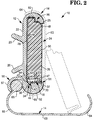
- Fig. 2 is a sectional view of the shelf unit of Fig. 1;
- Fig. 3 is a partial view of Fig. 2, illustrating the installation and removal of the electronic display module;
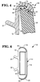
- Fig. 4 is a partial view of Fig. 2, illustrating electrical connection of the electronic display module;
- Fig. 5 is a perspective view of an alternative embodiment of the electronic shelf label mounting apparatus of the present invention; and
- Fig. 6 is an end view of an alternative embodiment of the electronic shelf label mounting apparatus of the present invention.
- Turning first to Figs. 1 and 2, electronic shelf label (ESL)
mounting system 10 includesrail member 12,cover member 14,hinge member 16 forcoupling cover member 14 torail member 12, andlocking pawl 18. -
Rail member 12 includeshook members 20 on therear side 22 thereof forcoupling rail member 12 to the front of a shelf (not shown) andchannel 24 for containingelectronic display module 26. Channel 24 is defined byupper wall 25,vertical wall 28, andlower wall 30. Access tochannel 24 is throughfront side 32 ofrail member 12. - In the preferred embodiment,
channel 24 further includesgroove 34 inlower wall 30.Groove 34 conforms to the shape offlexible locking pawl 18 onelectronic display module 26 and in this embodiment includesinclined wall portion 38 originating atlower edge 40 ofvertical wall 28 andvertical wall portion 42 connectinglower edge 44 ofinclined wall portion 38 andinner edge 46 oflower wall 30. -
Electronic display module 26 includeslower surface 47,upper surface 48,rear surface 49, andfront surface 50, and conforms to the shape ofchannel 24, having a height equal to the height ofvertical wall 28. The width ofelectronic display module 26 is slightly less than the width ofchannel 24 to protectelectronic display module 26 from contact with shopping carts. - Additionally,
electronic display module 26 includes invertedchannel 51 adjacent itslower surface 47. One end of invertedchannel 51 is infront surface 50 and in the preferred embodiment is rectangular in shape.Upper surface 52 of invertedchannel 51 is the lower surface offlexible locking pawl 18.Flexible locking pawl 18 extends rearwardly fromfront surface 50 ofelectronic display module 26, where it is flexibly hinged, and includesrectangular strip portion 53 andtriangular ridge portion 54 at the rear end ofstrip portion 53 having the same shape asgroove 34.Flexible locking pawl 18 is downwardly biased forengaging ridge portion 54 withgroove 34 to lockingly retainelectronic display module 26 inchannel 24. - Top and
bottom surfaces rail member 12 are rounded and are generally circular in cross-section. Advantageously, this geometry minimizes damage torail member 12 from contact with shopping carts, and cans being removed from the shelf. -
Protective cover 14 made of transparent plastic protectselectronic display module 26 from collisions with shopping carts and other routine wear.Protective cover 14 includesface member 63 that covers the front ofrail member 12, resilienttop lip member 64 extending fromface member 63 overtop surface 60, andbottom lip member 66 extending fromface member 63 overbottom surface 62. In this embodiment,cover 14 is rotatably mounted abouthinge member 16. Hingemember 16 includesflange 67 andcylindrical member 68 at the end ofbottom lip member 66 and constrained byflange 67.Protective cover 14 is removed by applying enough force to cause resilienttop lip member 64 to cleartop surface 60. - Referring now to Fig. 3,
key 70 is inserted into invertedchannel 48 to forceflexible locking pawl 18 upwards and unlockelectronic display module 26 fromchannel 24. The bottom ofelectronic display module 26 is then brought forward out ofchannel 24. - Referring now to Fig. 4, the electrical connections are shown in more detail.
Receptacles upper wall 25. Power and signal wires are connected toreceptacles terminal 76.Upper wall 25 includes L-shaped groove 78 havingfirst ceiling portion 80 andsecond ceiling portion 82 higher than thefirst ceiling portion 80. By locating the electrical connections on the first and second steps, the connections are also isolated from the channel opening. -
Electronic display module 26 has a shape similar to L-shaped groove 78.First step portion 84 is equipped withground contact 86 andsecond step portion 88, higher thanfirst step portion 84, has power andsignal contacts 90 and 92. This design minimizes the possibility of electrostatic discharge to display 26 by placing the ground connections closer to a user and by separatingground connections signal connections - Referring now to Fig. 5,
alternative embodiment 100 includeselectronic display module 26 employing twolocking pawls Key 106 having twoparallel members key 70, is used to simultaneously unlock bothlocking pawls - Referring now to Fig. 6,
alternative embodiment 112 employs hingelessprotective cover 114.Protective cover 114 hasface member 116 that covers the front ofrail member 12 and resilient top andbottom lip members face member 116 over top andbottom surfaces Protective cover 114 is removed by applying enough force to cause resilient top andbottom lip members bottom surfaces
Claims (10)
- A mounting system for an electronic shelf label system (10) including an electronic display module (26) for displaying price information, the mounting system (10) being characterized by a rail (12), having rounded top and bottom surfaces (60, 62) and a channel (24) defined by upper and lower walls (25,30) joined by a vertical wall (28), for containing the electronic display module (26), and a cover (14) for protecting the electronic display module (26) including a primary cover member (63), a top lip member (64) extending from the primary cover member (63) over the top surface (60) of the rail (12), and a bottom lip member (66) extending from the primary cover member (63) over the bottom surface (62) of the rail (12).
- A system according to claim 1, characterized by coupling means (16) for pivotally coupling the cover (14) to the rail (12).
- A system according to claim 2, characterized by the coupling means (10) including a flange (67) extending from the rail (12), and a cylindrical member (68) at the end of the bottom lip member (66) and constrained by the flange (68).
- A system according to anyone of the preceding claims characterized by connecting means (72, 74, 76, 86, 90, 92) for wirelessly and electrically connecting the electronic display module (26) to the rail (12).
- A system according to claim 4, characterized by the connecting means comprising a power receptacle (72) within the rail (12), a signal receptacle (74) within the rail (12), a ground receptacle (76) within the rail (12) at a predetermined location sufficient to minimize static discharge between the ground receptacle (76) and the power and signal receptacles (72, 74), a power terminal (90) within the electronic display module (26) positioned to operatively engage the power receptacle (72), a signal terminal (92) within the electronic display module (26) positioned to operatively engage the signal receptacle (74), and a ground terminal (86) within the electronic display module (26) at a predetermined location to operatively engage the ground receptacle (76) and to minimize static discharge between the ground terminal (86) and the power and signal terminals (90, 92).
- A system according to claim 5, characterized by the electronic display module (26) having an upper surface, and the system further comprising a first step portion (84) in the upper surface of the electronic display module (26) for mounting the ground terminal (86), a second step portion (88) in the upper surface of the electronic display module (26) higher than the first step portion (84) for mounting the power and signal terminals (90, 92), and an L-shaped groove in the upper wall of the channel (24) including a first ceiling portion (80) for receiving the first step portion (84) and for mounting the ground receptacle (76), and a second ceiling portion (82) higher than the first ceiling portion (84) for receiving the second step portion (88) and for mounting the power and signal receptacles (90, 92).
- A system according to any one of the preceding claims, characterized by locking means (18, 102, 104) for locking the electronic display module (26) in the rail (12).
- A system according to claim 7, characterized in that the electronic display module (26) has a front surface (50) and wherein the locking means (18, 102, 104) comprises a flexible pawl (18) extending from the front surface (50) of the electronic display module (26) including a strip member (53) and a triangular member (54) coupled to the strip member (53), and a triangular groove (34) within the lower wall of the channel for receiving the triangular member (54) when the electronic display module (26) is inserted into the channel (24).
- A system according to claim 8, characterized by a pair of flexible pawls (102, 104) extending from the front surface (50) of the electronic display module (26) including strip members and a triangular members coupled to the strip members, and means (106) for simultaneously unlocking both flexible pawls (102, 104).
- A system according to any one of the preceding claims, characterized in that the channel (24) is wider than the electronic display module (26).
Applications Claiming Priority (2)
| Application Number | Priority Date | Filing Date | Title |
|---|---|---|---|
| US08/245,196 US6069596A (en) | 1994-05-17 | 1994-05-17 | Electronic shelf label mounting system |
| US245196 | 1994-05-17 |
Publications (3)
| Publication Number | Publication Date |
|---|---|
| EP0683478A2 true EP0683478A2 (en) | 1995-11-22 |
| EP0683478A3 EP0683478A3 (en) | 1997-11-05 |
| EP0683478B1 EP0683478B1 (en) | 2000-09-06 |
Family
ID=22925697
Family Applications (1)
| Application Number | Title | Priority Date | Filing Date |
|---|---|---|---|
| EP95303226A Expired - Lifetime EP0683478B1 (en) | 1994-05-17 | 1995-05-12 | An electronic shelf label mounting system |
Country Status (4)
| Country | Link |
|---|---|
| US (1) | US6069596A (en) |
| EP (1) | EP0683478B1 (en) |
| JP (1) | JPH07319397A (en) |
| DE (1) | DE69518694T2 (en) |
Cited By (20)
| Publication number | Priority date | Publication date | Assignee | Title |
|---|---|---|---|---|
| EP0831445A2 (en) * | 1996-09-20 | 1998-03-25 | Interlabel S.p.A. | Adjustable device for coupling electronic labels to shelves and the like |
| US5736967A (en) * | 1993-09-03 | 1998-04-07 | Kayser Ventures, Ltd. | Article-information display system using electronically controlled tags |
| WO1998058360A1 (en) * | 1997-06-18 | 1998-12-23 | Store Electronic Systems Communication | Electronic labelling system |
| FR2765018A1 (en) * | 1997-06-18 | 1998-12-24 | Rasec Communication Sa | Electronic label system for labelling merchandise for sale |
| FR2765017A1 (en) * | 1997-06-18 | 1998-12-24 | Rasec Communication Sa | Electronic labelling system for display of prices on supermarket shelves |
| WO1999003174A1 (en) * | 1997-07-11 | 1999-01-21 | The Whitaker Corporation | Electrical connection assembly for rail mounted display |
| US6181299B1 (en) | 1993-09-03 | 2001-01-30 | Display Edge Technology, Ltd. | Power and communication system for electronic display tags |
| US6249263B1 (en) | 1993-09-03 | 2001-06-19 | Display Edge Technology, Ltd. | Article-information display system using electronically controlled tags |
| US6266052B1 (en) | 1993-09-03 | 2001-07-24 | Display Edge Technology, Ltd. | Power and information distribution system for article display or storage areas and related method |
| FR2844138A1 (en) * | 2002-08-28 | 2004-03-05 | Legrand Sa | Electrical distribution container/cupboard label holder having two transparent strips with connecting upper surface and lower surface having free edge closure mechanism. |
| GB2396949A (en) * | 2002-12-02 | 2004-07-07 | Aspects Design & Marketing Ltd | Price display unit |
| GB2464353A (en) * | 2008-10-15 | 2010-04-21 | Samsung Electro Mech | Shelf label mounting in particular for electronic shelf label (ESL) |
| GB2470086A (en) * | 2009-04-10 | 2010-11-10 | Samsung Electro Mech | Lockable electronic shelf label |
| EP2425750A1 (en) * | 2009-05-01 | 2012-03-07 | Optoelectronics Co., Ltd. | Electronic shelf tag |
| FR3001875A1 (en) * | 2013-02-13 | 2014-08-15 | Hl Display Ab | Electronic display arrangement for displaying e.g. information of products on shelf in grocery store, has insertion rib projecting in longitudinal manner for insertion with groove, and tenons for insertion into number of cavities |
| EP2808861A1 (en) * | 2013-05-28 | 2014-12-03 | Samsung Electro-Mechanics Co., Ltd. | Electronic tag and remover key of electronic tag |
| DE102015003723A1 (en) * | 2015-03-21 | 2016-09-22 | BEKAST IT Consulting GmbH | Data communication device, information reproducing device and display device for use in such |
| WO2016150430A1 (en) | 2015-03-21 | 2016-09-29 | BEKAST IT Consulting GmbH | Information reproduction device and display apparatus for use in such a device |
| EP3146871A1 (en) * | 2015-01-13 | 2017-03-29 | Umdasch Shopfitting GmbH | Holder for electronic price tags |
| WO2022218513A1 (en) * | 2021-04-13 | 2022-10-20 | Ses-Imagotag Gmbh | Support device for supporting an electronic device within a receiving area for the support device |
Families Citing this family (31)
| Publication number | Priority date | Publication date | Assignee | Title |
|---|---|---|---|---|
| JP4016230B2 (en) * | 1998-09-10 | 2007-12-05 | ソニー株式会社 | Panel display |
| US20020156634A1 (en) * | 1999-05-04 | 2002-10-24 | Blum Ronald D. | Floor mat with voice-responsive display |
| US6367752B1 (en) * | 1999-10-20 | 2002-04-09 | Ncr Corporation | Electronic price label mounting apparatus |
| US6715675B1 (en) * | 2000-11-16 | 2004-04-06 | Eldat Communication Ltd. | Electronic shelf label systems and methods |
| US6770186B2 (en) | 2001-11-13 | 2004-08-03 | Eldat Communication Ltd. | Rechargeable hydrogen-fueled motor vehicle |
| US7074509B2 (en) | 2001-11-13 | 2006-07-11 | Eldat Communication Ltd. | Hydrogen generators for fuel cells |
| US7018129B1 (en) * | 2002-09-06 | 2006-03-28 | Herwin Inc. | Enhanced guardrail |
| US20040165015A1 (en) * | 2003-02-20 | 2004-08-26 | Blum Ronald D. | Electronic display device for floor advertising/messaging |
| US7159352B1 (en) | 2003-03-11 | 2007-01-09 | Daniel Lefebvre | End cap apparatus |
| US20050237153A1 (en) * | 2004-04-21 | 2005-10-27 | Jack Chen | Device for electronically pricing product on a shelf |
| US7308770B2 (en) * | 2004-11-02 | 2007-12-18 | Fast Industries, Ltd | Electronic shelf label holder for scanner plate and wire supports |
| US7424785B2 (en) * | 2004-12-20 | 2008-09-16 | Emc Corporation | Label cassette for an electronics enclosure |
| WO2008095121A2 (en) * | 2007-01-31 | 2008-08-07 | Design Ind Inc | Support systems and components for same |
| KR20100126427A (en) * | 2008-02-21 | 2010-12-01 | 마리센스 오이 | Display module and related manufacturing method |
| KR101004862B1 (en) | 2008-08-08 | 2010-12-28 | 삼성전기주식회사 | Electronic Shelf Label |
| SE534688C2 (en) * | 2009-03-20 | 2011-11-15 | Pricer Ab | Electronic shelf label and holder including locking mechanism, and locking mechanism |
| SE534425C2 (en) * | 2009-03-20 | 2011-08-16 | Pricer Ab | Electronic shelf label and holder including locking mechanism, and locking mechanism |
| US20110205201A1 (en) * | 2010-02-20 | 2011-08-25 | Lorkowski Technologies Llc | Microencapsulated electrophoretic price display system |
| US20120209670A1 (en) * | 2011-02-16 | 2012-08-16 | Carl Zealer | Configurable advertising and content rendering |
| GB201120862D0 (en) * | 2011-12-05 | 2012-01-18 | Airbus Operations Ltd | A wingtip fin of an aircraft |
| CN103988243B (en) | 2011-12-14 | 2017-09-12 | 英特尔公司 | Minitype digital billboard hardware integration |
| KR101503993B1 (en) * | 2013-01-08 | 2015-03-18 | 삼성전기주식회사 | Electronic label device |
| FR3003068B1 (en) * | 2013-03-11 | 2015-05-15 | Store Elect Sys | ELECTRONIC LABELING SYSTEM |
| US9147355B2 (en) * | 2013-03-15 | 2015-09-29 | Checkpoint Systems, Inc. | Advertisement clip for hard tags |
| US9911138B2 (en) | 2013-04-19 | 2018-03-06 | Wal-Mart Stores, Inc. | Automated limited-time retail merchandise promotion system |
| DE202014105612U1 (en) * | 2014-11-21 | 2016-02-23 | Rehau Ag + Co | display arrangement |
| CA2876325A1 (en) * | 2014-12-31 | 2016-06-30 | Fitneff Inc. | Clip and rail attachment system |
| US10083638B2 (en) * | 2017-02-06 | 2018-09-25 | Spec Seats Technologies Inc. | Edge side display device for a chair |
| KR102086803B1 (en) * | 2018-04-16 | 2020-03-09 | 김현학 | Electric Label Fixing Device |
| US11232720B2 (en) | 2020-04-30 | 2022-01-25 | Bby Solutions, Inc. | Display holders and adapters system |
| CN113990208B (en) * | 2021-12-15 | 2024-02-27 | 深圳市华森通智能科技有限公司 | Electronic intelligent label |
Citations (3)
| Publication number | Priority date | Publication date | Assignee | Title |
|---|---|---|---|---|
| GB2249854A (en) * | 1990-10-17 | 1992-05-20 | Sainsbury J Plc | Electronic labels |
| GB2266401A (en) * | 1992-03-25 | 1993-10-27 | Clares Equip Ltd | Shelf label holder. |
| EP0623873A1 (en) * | 1993-05-05 | 1994-11-09 | Esselte Meto International GmbH | Device for displaying prices-electronically on shelves |
Family Cites Families (11)
| Publication number | Priority date | Publication date | Assignee | Title |
|---|---|---|---|---|
| US4002886A (en) * | 1975-06-20 | 1977-01-11 | Ronald Murl Sundelin | Electronic price display unit |
| US4500880A (en) * | 1981-07-06 | 1985-02-19 | Motorola, Inc. | Real time, computer-driven retail pricing display system |
| US4577428A (en) * | 1983-06-27 | 1986-03-25 | Everbrite Electric Signs, Inc. | Display device with movable tape assemblies |
| US4562657A (en) * | 1984-05-16 | 1986-01-07 | General Indicator Corporation | Display structure |
| US4593486A (en) * | 1984-12-27 | 1986-06-10 | Plasti-Line, Inc. | Menu and prices display device |
| US4821440A (en) * | 1986-10-20 | 1989-04-18 | Dunn Gary D | Weatherized construction site inspection board assembly |
| SE462353B (en) * | 1988-09-13 | 1990-06-11 | Svenska S C I M Ab | TELLER SHOULD BE SHEET OR CORRECT INFORMATION BEARERS |
| US5237767A (en) * | 1989-02-17 | 1993-08-24 | Actmedia | Mounting device |
| DE8904664U1 (en) * | 1989-04-13 | 1989-06-01 | Rehau Ag + Co, 8673 Rehau, De | |
| US5189822A (en) * | 1990-08-24 | 1993-03-02 | Carsonite International | Tamper resistant sign |
| US5241467A (en) * | 1992-04-30 | 1993-08-31 | Ers Associates Limited Partnership | Space management system |
-
1994
- 1994-05-17 US US08/245,196 patent/US6069596A/en not_active Expired - Lifetime
-
1995
- 1995-05-10 JP JP7111410A patent/JPH07319397A/en active Pending
- 1995-05-12 EP EP95303226A patent/EP0683478B1/en not_active Expired - Lifetime
- 1995-05-12 DE DE69518694T patent/DE69518694T2/en not_active Expired - Fee Related
Patent Citations (3)
| Publication number | Priority date | Publication date | Assignee | Title |
|---|---|---|---|---|
| GB2249854A (en) * | 1990-10-17 | 1992-05-20 | Sainsbury J Plc | Electronic labels |
| GB2266401A (en) * | 1992-03-25 | 1993-10-27 | Clares Equip Ltd | Shelf label holder. |
| EP0623873A1 (en) * | 1993-05-05 | 1994-11-09 | Esselte Meto International GmbH | Device for displaying prices-electronically on shelves |
Cited By (27)
| Publication number | Priority date | Publication date | Assignee | Title |
|---|---|---|---|---|
| US6181299B1 (en) | 1993-09-03 | 2001-01-30 | Display Edge Technology, Ltd. | Power and communication system for electronic display tags |
| US5736967A (en) * | 1993-09-03 | 1998-04-07 | Kayser Ventures, Ltd. | Article-information display system using electronically controlled tags |
| US6271807B1 (en) | 1993-09-03 | 2001-08-07 | Display Edge Technology, Ltd. | Method of initializing, controlling and updating electronic display tags and related controller therefor |
| US6266052B1 (en) | 1993-09-03 | 2001-07-24 | Display Edge Technology, Ltd. | Power and information distribution system for article display or storage areas and related method |
| US6249263B1 (en) | 1993-09-03 | 2001-06-19 | Display Edge Technology, Ltd. | Article-information display system using electronically controlled tags |
| EP0831445A3 (en) * | 1996-09-20 | 1998-09-23 | Interlabel S.p.A. | Adjustable device for coupling electronic labels to shelves and the like |
| EP0831445A2 (en) * | 1996-09-20 | 1998-03-25 | Interlabel S.p.A. | Adjustable device for coupling electronic labels to shelves and the like |
| US6418651B1 (en) | 1997-06-18 | 2002-07-16 | Store Electronic Systems Communication | Electronic labeling system |
| FR2765017A1 (en) * | 1997-06-18 | 1998-12-24 | Rasec Communication Sa | Electronic labelling system for display of prices on supermarket shelves |
| FR2765018A1 (en) * | 1997-06-18 | 1998-12-24 | Rasec Communication Sa | Electronic label system for labelling merchandise for sale |
| FR2765019A1 (en) * | 1997-06-18 | 1998-12-24 | Label 41 | ELECTRONIC LABELING SYSTEM |
| WO1998058360A1 (en) * | 1997-06-18 | 1998-12-23 | Store Electronic Systems Communication | Electronic labelling system |
| WO1999003174A1 (en) * | 1997-07-11 | 1999-01-21 | The Whitaker Corporation | Electrical connection assembly for rail mounted display |
| FR2844138A1 (en) * | 2002-08-28 | 2004-03-05 | Legrand Sa | Electrical distribution container/cupboard label holder having two transparent strips with connecting upper surface and lower surface having free edge closure mechanism. |
| GB2396949A (en) * | 2002-12-02 | 2004-07-07 | Aspects Design & Marketing Ltd | Price display unit |
| GB2464353B (en) * | 2008-10-15 | 2012-10-10 | Samsung Electro Mech | Price Display apparatus |
| GB2464353A (en) * | 2008-10-15 | 2010-04-21 | Samsung Electro Mech | Shelf label mounting in particular for electronic shelf label (ESL) |
| GB2470086A (en) * | 2009-04-10 | 2010-11-10 | Samsung Electro Mech | Lockable electronic shelf label |
| GB2470086B (en) * | 2009-04-10 | 2011-06-22 | Samsung Electro Mech | Electronic shelf label assembly |
| EP2425750A1 (en) * | 2009-05-01 | 2012-03-07 | Optoelectronics Co., Ltd. | Electronic shelf tag |
| EP2425750A4 (en) * | 2009-05-01 | 2012-12-05 | Optoelectronics Co Ltd | Electronic shelf tag |
| FR3001875A1 (en) * | 2013-02-13 | 2014-08-15 | Hl Display Ab | Electronic display arrangement for displaying e.g. information of products on shelf in grocery store, has insertion rib projecting in longitudinal manner for insertion with groove, and tenons for insertion into number of cavities |
| EP2808861A1 (en) * | 2013-05-28 | 2014-12-03 | Samsung Electro-Mechanics Co., Ltd. | Electronic tag and remover key of electronic tag |
| EP3146871A1 (en) * | 2015-01-13 | 2017-03-29 | Umdasch Shopfitting GmbH | Holder for electronic price tags |
| DE102015003723A1 (en) * | 2015-03-21 | 2016-09-22 | BEKAST IT Consulting GmbH | Data communication device, information reproducing device and display device for use in such |
| WO2016150430A1 (en) | 2015-03-21 | 2016-09-29 | BEKAST IT Consulting GmbH | Information reproduction device and display apparatus for use in such a device |
| WO2022218513A1 (en) * | 2021-04-13 | 2022-10-20 | Ses-Imagotag Gmbh | Support device for supporting an electronic device within a receiving area for the support device |
Also Published As
| Publication number | Publication date |
|---|---|
| EP0683478A3 (en) | 1997-11-05 |
| JPH07319397A (en) | 1995-12-08 |
| DE69518694T2 (en) | 2001-05-31 |
| DE69518694D1 (en) | 2000-10-12 |
| US6069596A (en) | 2000-05-30 |
| EP0683478B1 (en) | 2000-09-06 |
Similar Documents
| Publication | Publication Date | Title |
|---|---|---|
| EP0683478B1 (en) | An electronic shelf label mounting system | |
| EP0689180A1 (en) | An electronic shelf label protective cover | |
| EP0768633B1 (en) | Shelf mounted electronic display modules | |
| US6126125A (en) | Electronic price label mounting device | |
| WO2004012172A1 (en) | Label holder for electronic labeling devices | |
| US4351440A (en) | Merchandise hook | |
| US5348485A (en) | Electronic price display system with vertical rail | |
| US6119990A (en) | Holder for electronic information carrier | |
| CA1174744A (en) | Vehicle mounted mobile business data handling system | |
| US7287350B2 (en) | Fixed angle ESL label holder with flex grip and moisture seal | |
| US6105295A (en) | Label holder for attachment to different shelf channels | |
| CA2200553C (en) | Article-information display system using electronically controlled tags | |
| EP0434726B1 (en) | Label holder | |
| US4828121A (en) | Shelf expander for supermarkets | |
| WO1997048862A9 (en) | Holder for electronic information carrier | |
| US7367149B2 (en) | Label holder | |
| US5500489A (en) | Cable for electronic retailing applications | |
| US6146158A (en) | Self-adjusting shelf mounted interconnect for a digital display | |
| CA2155597C (en) | Product identification and exhibiting system | |
| CN113706805A (en) | Merchandise security system | |
| GB2277188A (en) | Intermediate bulk container marking plate | |
| GB2470086A (en) | Lockable electronic shelf label | |
| US20050218280A1 (en) | Scanner plate hook and hook back plate for perforated boards | |
| WO2003070064A1 (en) | Holder device for mounting on shelves in shops | |
| US4090613A (en) | Storage device |
Legal Events
| Date | Code | Title | Description |
|---|---|---|---|
| PUAI | Public reference made under article 153(3) epc to a published international application that has entered the european phase |
Free format text: ORIGINAL CODE: 0009012 |
|
| AK | Designated contracting states |
Kind code of ref document: A2 Designated state(s): DE FR GB |
|
| RIN1 | Information on inventor provided before grant (corrected) |
Inventor name: CARR, DONALD WILLIAM Inventor name: MARVIN, RUSSEL H. |
|
| RAP1 | Party data changed (applicant data changed or rights of an application transferred) |
Owner name: NCR INTERNATIONAL, INC. |
|
| PUAL | Search report despatched |
Free format text: ORIGINAL CODE: 0009013 |
|
| AK | Designated contracting states |
Kind code of ref document: A3 Designated state(s): DE FR GB |
|
| 17P | Request for examination filed |
Effective date: 19980506 |
|
| GRAG | Despatch of communication of intention to grant |
Free format text: ORIGINAL CODE: EPIDOS AGRA |
|
| 17Q | First examination report despatched |
Effective date: 19991201 |
|
| GRAG | Despatch of communication of intention to grant |
Free format text: ORIGINAL CODE: EPIDOS AGRA |
|
| GRAH | Despatch of communication of intention to grant a patent |
Free format text: ORIGINAL CODE: EPIDOS IGRA |
|
| GRAH | Despatch of communication of intention to grant a patent |
Free format text: ORIGINAL CODE: EPIDOS IGRA |
|
| GRAA | (expected) grant |
Free format text: ORIGINAL CODE: 0009210 |
|
| AK | Designated contracting states |
Kind code of ref document: B1 Designated state(s): DE FR GB |
|
| REF | Corresponds to: |
Ref document number: 69518694 Country of ref document: DE Date of ref document: 20001012 |
|
| ET | Fr: translation filed | ||
| PLBE | No opposition filed within time limit |
Free format text: ORIGINAL CODE: 0009261 |
|
| STAA | Information on the status of an ep patent application or granted ep patent |
Free format text: STATUS: NO OPPOSITION FILED WITHIN TIME LIMIT |
|
| 26N | No opposition filed | ||
| REG | Reference to a national code |
Ref country code: GB Ref legal event code: IF02 |
|
| REG | Reference to a national code |
Ref country code: GB Ref legal event code: 746 Effective date: 20030402 |
|
| REG | Reference to a national code |
Ref country code: FR Ref legal event code: D6 |
|
| PGFP | Annual fee paid to national office [announced via postgrant information from national office to epo] |
Ref country code: GB Payment date: 20050504 Year of fee payment: 11 |
|
| PGFP | Annual fee paid to national office [announced via postgrant information from national office to epo] |
Ref country code: FR Payment date: 20050512 Year of fee payment: 11 |
|
| PGFP | Annual fee paid to national office [announced via postgrant information from national office to epo] |
Ref country code: DE Payment date: 20050525 Year of fee payment: 11 |
|
| PG25 | Lapsed in a contracting state [announced via postgrant information from national office to epo] |
Ref country code: GB Free format text: LAPSE BECAUSE OF NON-PAYMENT OF DUE FEES Effective date: 20060512 |
|
| PG25 | Lapsed in a contracting state [announced via postgrant information from national office to epo] |
Ref country code: DE Free format text: LAPSE BECAUSE OF NON-PAYMENT OF DUE FEES Effective date: 20061201 |
|
| GBPC | Gb: european patent ceased through non-payment of renewal fee |
Effective date: 20060512 |
|
| REG | Reference to a national code |
Ref country code: FR Ref legal event code: ST Effective date: 20070131 |
|
| PG25 | Lapsed in a contracting state [announced via postgrant information from national office to epo] |
Ref country code: FR Free format text: LAPSE BECAUSE OF NON-PAYMENT OF DUE FEES Effective date: 20060531 |