EP0680284B1 - Cryogenic catheter - Google Patents
Cryogenic catheter Download PDFInfo
- Publication number
- EP0680284B1 EP0680284B1 EP93912285A EP93912285A EP0680284B1 EP 0680284 B1 EP0680284 B1 EP 0680284B1 EP 93912285 A EP93912285 A EP 93912285A EP 93912285 A EP93912285 A EP 93912285A EP 0680284 B1 EP0680284 B1 EP 0680284B1
- Authority
- EP
- European Patent Office
- Prior art keywords
- catheter
- distal end
- lumen
- electrode
- ablation
- Prior art date
- Legal status (The legal status is an assumption and is not a legal conclusion. Google has not performed a legal analysis and makes no representation as to the accuracy of the status listed.)
- Expired - Lifetime
Links
Images


Classifications
-
- A—HUMAN NECESSITIES
- A61—MEDICAL OR VETERINARY SCIENCE; HYGIENE
- A61M—DEVICES FOR INTRODUCING MEDIA INTO, OR ONTO, THE BODY; DEVICES FOR TRANSDUCING BODY MEDIA OR FOR TAKING MEDIA FROM THE BODY; DEVICES FOR PRODUCING OR ENDING SLEEP OR STUPOR
- A61M25/00—Catheters; Hollow probes
- A61M25/01—Introducing, guiding, advancing, emplacing or holding catheters
- A61M25/0105—Steering means as part of the catheter or advancing means; Markers for positioning
- A61M25/0133—Tip steering devices
- A61M25/0158—Tip steering devices with magnetic or electrical means, e.g. by using piezo materials, electroactive polymers, magnetic materials or by heating of shape memory materials
-
- A—HUMAN NECESSITIES
- A61—MEDICAL OR VETERINARY SCIENCE; HYGIENE
- A61B—DIAGNOSIS; SURGERY; IDENTIFICATION
- A61B18/00—Surgical instruments, devices or methods for transferring non-mechanical forms of energy to or from the body
- A61B18/02—Surgical instruments, devices or methods for transferring non-mechanical forms of energy to or from the body by cooling, e.g. cryogenic techniques
-
- A—HUMAN NECESSITIES
- A61—MEDICAL OR VETERINARY SCIENCE; HYGIENE
- A61B—DIAGNOSIS; SURGERY; IDENTIFICATION
- A61B18/00—Surgical instruments, devices or methods for transferring non-mechanical forms of energy to or from the body
- A61B18/04—Surgical instruments, devices or methods for transferring non-mechanical forms of energy to or from the body by heating
- A61B18/12—Surgical instruments, devices or methods for transferring non-mechanical forms of energy to or from the body by heating by passing a current through the tissue to be heated, e.g. high-frequency current
- A61B18/14—Probes or electrodes therefor
- A61B18/1492—Probes or electrodes therefor having a flexible, catheter-like structure, e.g. for heart ablation
-
- A—HUMAN NECESSITIES
- A61—MEDICAL OR VETERINARY SCIENCE; HYGIENE
- A61B—DIAGNOSIS; SURGERY; IDENTIFICATION
- A61B18/00—Surgical instruments, devices or methods for transferring non-mechanical forms of energy to or from the body
- A61B18/04—Surgical instruments, devices or methods for transferring non-mechanical forms of energy to or from the body by heating
- A61B18/12—Surgical instruments, devices or methods for transferring non-mechanical forms of energy to or from the body by heating by passing a current through the tissue to be heated, e.g. high-frequency current
- A61B18/14—Probes or electrodes therefor
-
- A—HUMAN NECESSITIES
- A61—MEDICAL OR VETERINARY SCIENCE; HYGIENE
- A61B—DIAGNOSIS; SURGERY; IDENTIFICATION
- A61B18/00—Surgical instruments, devices or methods for transferring non-mechanical forms of energy to or from the body
- A61B18/18—Surgical instruments, devices or methods for transferring non-mechanical forms of energy to or from the body by applying electromagnetic radiation, e.g. microwaves
- A61B18/20—Surgical instruments, devices or methods for transferring non-mechanical forms of energy to or from the body by applying electromagnetic radiation, e.g. microwaves using laser
- A61B18/22—Surgical instruments, devices or methods for transferring non-mechanical forms of energy to or from the body by applying electromagnetic radiation, e.g. microwaves using laser the beam being directed along or through a flexible conduit, e.g. an optical fibre; Couplings or hand-pieces therefor
- A61B18/24—Surgical instruments, devices or methods for transferring non-mechanical forms of energy to or from the body by applying electromagnetic radiation, e.g. microwaves using laser the beam being directed along or through a flexible conduit, e.g. an optical fibre; Couplings or hand-pieces therefor with a catheter
-
- A—HUMAN NECESSITIES
- A61—MEDICAL OR VETERINARY SCIENCE; HYGIENE
- A61B—DIAGNOSIS; SURGERY; IDENTIFICATION
- A61B18/00—Surgical instruments, devices or methods for transferring non-mechanical forms of energy to or from the body
- A61B18/18—Surgical instruments, devices or methods for transferring non-mechanical forms of energy to or from the body by applying electromagnetic radiation, e.g. microwaves
- A61B18/20—Surgical instruments, devices or methods for transferring non-mechanical forms of energy to or from the body by applying electromagnetic radiation, e.g. microwaves using laser
- A61B18/22—Surgical instruments, devices or methods for transferring non-mechanical forms of energy to or from the body by applying electromagnetic radiation, e.g. microwaves using laser the beam being directed along or through a flexible conduit, e.g. an optical fibre; Couplings or hand-pieces therefor
- A61B18/28—Surgical instruments, devices or methods for transferring non-mechanical forms of energy to or from the body by applying electromagnetic radiation, e.g. microwaves using laser the beam being directed along or through a flexible conduit, e.g. an optical fibre; Couplings or hand-pieces therefor for heating a thermal probe or absorber
-
- A—HUMAN NECESSITIES
- A61—MEDICAL OR VETERINARY SCIENCE; HYGIENE
- A61B—DIAGNOSIS; SURGERY; IDENTIFICATION
- A61B17/00—Surgical instruments, devices or methods, e.g. tourniquets
- A61B2017/00017—Electrical control of surgical instruments
-
- A—HUMAN NECESSITIES
- A61—MEDICAL OR VETERINARY SCIENCE; HYGIENE
- A61B—DIAGNOSIS; SURGERY; IDENTIFICATION
- A61B17/00—Surgical instruments, devices or methods, e.g. tourniquets
- A61B2017/00017—Electrical control of surgical instruments
- A61B2017/00022—Sensing or detecting at the treatment site
-
- A—HUMAN NECESSITIES
- A61—MEDICAL OR VETERINARY SCIENCE; HYGIENE
- A61B—DIAGNOSIS; SURGERY; IDENTIFICATION
- A61B17/00—Surgical instruments, devices or methods, e.g. tourniquets
- A61B17/00234—Surgical instruments, devices or methods, e.g. tourniquets for minimally invasive surgery
- A61B2017/00238—Type of minimally invasive operation
- A61B2017/00243—Type of minimally invasive operation cardiac
-
- A—HUMAN NECESSITIES
- A61—MEDICAL OR VETERINARY SCIENCE; HYGIENE
- A61B—DIAGNOSIS; SURGERY; IDENTIFICATION
- A61B17/00—Surgical instruments, devices or methods, e.g. tourniquets
- A61B17/00234—Surgical instruments, devices or methods, e.g. tourniquets for minimally invasive surgery
- A61B2017/00292—Surgical instruments, devices or methods, e.g. tourniquets for minimally invasive surgery mounted on or guided by flexible, e.g. catheter-like, means
- A61B2017/003—Steerable
-
- A—HUMAN NECESSITIES
- A61—MEDICAL OR VETERINARY SCIENCE; HYGIENE
- A61B—DIAGNOSIS; SURGERY; IDENTIFICATION
- A61B18/00—Surgical instruments, devices or methods for transferring non-mechanical forms of energy to or from the body
- A61B2018/00005—Cooling or heating of the probe or tissue immediately surrounding the probe
- A61B2018/00011—Cooling or heating of the probe or tissue immediately surrounding the probe with fluids
- A61B2018/00023—Cooling or heating of the probe or tissue immediately surrounding the probe with fluids closed, i.e. without wound contact by the fluid
-
- A—HUMAN NECESSITIES
- A61—MEDICAL OR VETERINARY SCIENCE; HYGIENE
- A61B—DIAGNOSIS; SURGERY; IDENTIFICATION
- A61B18/00—Surgical instruments, devices or methods for transferring non-mechanical forms of energy to or from the body
- A61B2018/00053—Mechanical features of the instrument of device
- A61B2018/00059—Material properties
- A61B2018/00071—Electrical conductivity
- A61B2018/00077—Electrical conductivity high, i.e. electrically conducting
-
- A—HUMAN NECESSITIES
- A61—MEDICAL OR VETERINARY SCIENCE; HYGIENE
- A61B—DIAGNOSIS; SURGERY; IDENTIFICATION
- A61B18/00—Surgical instruments, devices or methods for transferring non-mechanical forms of energy to or from the body
- A61B2018/00053—Mechanical features of the instrument of device
- A61B2018/00059—Material properties
- A61B2018/00089—Thermal conductivity
- A61B2018/00095—Thermal conductivity high, i.e. heat conducting
-
- A—HUMAN NECESSITIES
- A61—MEDICAL OR VETERINARY SCIENCE; HYGIENE
- A61B—DIAGNOSIS; SURGERY; IDENTIFICATION
- A61B18/00—Surgical instruments, devices or methods for transferring non-mechanical forms of energy to or from the body
- A61B2018/00315—Surgical instruments, devices or methods for transferring non-mechanical forms of energy to or from the body for treatment of particular body parts
- A61B2018/00345—Vascular system
- A61B2018/00351—Heart
- A61B2018/00357—Endocardium
-
- A—HUMAN NECESSITIES
- A61—MEDICAL OR VETERINARY SCIENCE; HYGIENE
- A61B—DIAGNOSIS; SURGERY; IDENTIFICATION
- A61B18/00—Surgical instruments, devices or methods for transferring non-mechanical forms of energy to or from the body
- A61B2018/00571—Surgical instruments, devices or methods for transferring non-mechanical forms of energy to or from the body for achieving a particular surgical effect
- A61B2018/00577—Ablation
-
- A—HUMAN NECESSITIES
- A61—MEDICAL OR VETERINARY SCIENCE; HYGIENE
- A61B—DIAGNOSIS; SURGERY; IDENTIFICATION
- A61B18/00—Surgical instruments, devices or methods for transferring non-mechanical forms of energy to or from the body
- A61B2018/00636—Sensing and controlling the application of energy
- A61B2018/00773—Sensed parameters
- A61B2018/00791—Temperature
- A61B2018/00815—Temperature measured by a thermistor
-
- A—HUMAN NECESSITIES
- A61—MEDICAL OR VETERINARY SCIENCE; HYGIENE
- A61B—DIAGNOSIS; SURGERY; IDENTIFICATION
- A61B18/00—Surgical instruments, devices or methods for transferring non-mechanical forms of energy to or from the body
- A61B2018/00636—Sensing and controlling the application of energy
- A61B2018/00773—Sensed parameters
- A61B2018/00791—Temperature
- A61B2018/00821—Temperature measured by a thermocouple
-
- A—HUMAN NECESSITIES
- A61—MEDICAL OR VETERINARY SCIENCE; HYGIENE
- A61B—DIAGNOSIS; SURGERY; IDENTIFICATION
- A61B18/00—Surgical instruments, devices or methods for transferring non-mechanical forms of energy to or from the body
- A61B2018/00636—Sensing and controlling the application of energy
- A61B2018/00773—Sensed parameters
- A61B2018/00839—Bioelectrical parameters, e.g. ECG, EEG
-
- A—HUMAN NECESSITIES
- A61—MEDICAL OR VETERINARY SCIENCE; HYGIENE
- A61B—DIAGNOSIS; SURGERY; IDENTIFICATION
- A61B18/00—Surgical instruments, devices or methods for transferring non-mechanical forms of energy to or from the body
- A61B18/02—Surgical instruments, devices or methods for transferring non-mechanical forms of energy to or from the body by cooling, e.g. cryogenic techniques
- A61B2018/0212—Surgical instruments, devices or methods for transferring non-mechanical forms of energy to or from the body by cooling, e.g. cryogenic techniques using an instrument inserted into a body lumen, e.g. catheter
-
- A—HUMAN NECESSITIES
- A61—MEDICAL OR VETERINARY SCIENCE; HYGIENE
- A61B—DIAGNOSIS; SURGERY; IDENTIFICATION
- A61B18/00—Surgical instruments, devices or methods for transferring non-mechanical forms of energy to or from the body
- A61B18/02—Surgical instruments, devices or methods for transferring non-mechanical forms of energy to or from the body by cooling, e.g. cryogenic techniques
- A61B2018/0231—Characteristics of handpieces or probes
- A61B2018/0262—Characteristics of handpieces or probes using a circulating cryogenic fluid
- A61B2018/0268—Characteristics of handpieces or probes using a circulating cryogenic fluid with restriction of flow
- A61B2018/0275—Characteristics of handpieces or probes using a circulating cryogenic fluid with restriction of flow using porous elements
-
- A—HUMAN NECESSITIES
- A61—MEDICAL OR VETERINARY SCIENCE; HYGIENE
- A61B—DIAGNOSIS; SURGERY; IDENTIFICATION
- A61B18/00—Surgical instruments, devices or methods for transferring non-mechanical forms of energy to or from the body
- A61B18/02—Surgical instruments, devices or methods for transferring non-mechanical forms of energy to or from the body by cooling, e.g. cryogenic techniques
- A61B2018/0231—Characteristics of handpieces or probes
- A61B2018/0262—Characteristics of handpieces or probes using a circulating cryogenic fluid
- A61B2018/0268—Characteristics of handpieces or probes using a circulating cryogenic fluid with restriction of flow
- A61B2018/0281—Characteristics of handpieces or probes using a circulating cryogenic fluid with restriction of flow using a tortuous path, e.g. formed by fins or ribs
-
- A—HUMAN NECESSITIES
- A61—MEDICAL OR VETERINARY SCIENCE; HYGIENE
- A61B—DIAGNOSIS; SURGERY; IDENTIFICATION
- A61B18/00—Surgical instruments, devices or methods for transferring non-mechanical forms of energy to or from the body
- A61B18/04—Surgical instruments, devices or methods for transferring non-mechanical forms of energy to or from the body by heating
- A61B18/12—Surgical instruments, devices or methods for transferring non-mechanical forms of energy to or from the body by heating by passing a current through the tissue to be heated, e.g. high-frequency current
- A61B18/1206—Generators therefor
- A61B2018/1246—Generators therefor characterised by the output polarity
- A61B2018/1253—Generators therefor characterised by the output polarity monopolar
-
- A—HUMAN NECESSITIES
- A61—MEDICAL OR VETERINARY SCIENCE; HYGIENE
- A61B—DIAGNOSIS; SURGERY; IDENTIFICATION
- A61B2218/00—Details of surgical instruments, devices or methods for transferring non-mechanical forms of energy to or from the body
- A61B2218/001—Details of surgical instruments, devices or methods for transferring non-mechanical forms of energy to or from the body having means for irrigation and/or aspiration of substances to and/or from the surgical site
- A61B2218/002—Irrigation
- A61B2218/003—Irrigation using a spray or a foam
-
- A—HUMAN NECESSITIES
- A61—MEDICAL OR VETERINARY SCIENCE; HYGIENE
- A61F—FILTERS IMPLANTABLE INTO BLOOD VESSELS; PROSTHESES; DEVICES PROVIDING PATENCY TO, OR PREVENTING COLLAPSING OF, TUBULAR STRUCTURES OF THE BODY, e.g. STENTS; ORTHOPAEDIC, NURSING OR CONTRACEPTIVE DEVICES; FOMENTATION; TREATMENT OR PROTECTION OF EYES OR EARS; BANDAGES, DRESSINGS OR ABSORBENT PADS; FIRST-AID KITS
- A61F7/00—Heating or cooling appliances for medical or therapeutic treatment of the human body
- A61F2007/0054—Heating or cooling appliances for medical or therapeutic treatment of the human body with a closed fluid circuit, e.g. hot water
- A61F2007/0056—Heating or cooling appliances for medical or therapeutic treatment of the human body with a closed fluid circuit, e.g. hot water for cooling
Definitions
- the invention relates to the field of catheters, and more particularly to a catheter used in cardiac procedures.
- Cardiac arrhythmias are caused by localized electrophysiologic phenomena. These are of generally two types: additional foci or reentrant circuits.
- Reentrant circuits can be highly localized, as in ventricular tachycardia postinfarction or AV node reentry, or can be of a grosser morphology, as in accessory pathway pathologies. Since they are localized phenomena, they can be treated surgically. The task is to remove or destroy the offending region, thereby eliminating the source of the arrhythmia.
- Radio frequency catheter ablation is becoming the therapy of choice.
- the greatest drawback of rf ablation is that, prior to ablation, the site of the intended cardiac lesion must be determined by conventional electrocardiographic mapping.
- conventional mapping does not provide definitive isolation of the problem area.
- more than one lesion must be made in order to effect a cure.
- Multiple lesions are required because the effectiveness of each of the proposed lesion sites cannot be predetermined due to the limitations of conventional electrocardiographic mapping. Often five lesions, and sometimes as many as twenty lesions may be required before a successful result is obtained. Usually only one of the lesions is actually effective; the other lesions result in unnecessarily destroyed cardiac tissue.
- Treatment of cardiac arrhythmias through selective ablation of cardiac tissue may be improved if, prior to ablation, the local electrical activity of the region can be suppressed to determine the effectiveness of the proposed lesion site in stopping the arrhythmia.
- Localized electrical activity may be suppressed by chilling small regions of myocardial tissue and then performing electrocardiographic mapping to evaluate the arrhythmia. This technique of cooling and mapping is called "zero-degree" or "ice” mapping. If the proposed lesion site would be effective, as determined by the ice mapping, to eliminate the arrhythmia, the site is ablated.
- cryoablation it has not been the technique of choice for want of a single, easily operated device which effectively combines the functions of cryogenic cooling of cardiac tissue and tissue ablation.
- Patent document US-A-3 524 446 describes a catheter in which can be identified the characteristics set forth in the preamble of claim 1.
- the invention concerns a catheter according to Claim 1.
- the invention provides an ablation catheter which combines zero-degree or ice mapping and tissue ablation means in a single device.
- the invention includes a first and a second lumen for circulating a cooling fluid to the distal end of a catheter which includes an ablation device.
- the ablation device may be one pole of a multipole mapping electrode which conducts radio frequency energy, or direct current energy for tissue ablation.
- the ablation electrode may be replaced with an optical fiber in communication with a laser.
- the light energy is dispersed by a light diffuser toward a lesion site to ablate the tissue.
- the catheter may have an optional steering device to curve the distal end of the catheter, and the ablation device may be held in contact with the myocardial tissue with the aid of a pointed ridge.
- the catheter is insertable through an artery or vein into the heart or into a cardiac vessel and placed against the site of a proposed lesion. Cooling fluid is circulated to the tip of the catheter through the lumens, thereby cooling a localized region of cardiac tissue. The electrical activity of the heart is then measured to evaluate the effectiveness of the proposed site. If the test results indicate that a lesion would eliminate a cardiac arrhythmia, the region is ablated with either radio frequency, direct current or laser light energy.
- Yet another embodiment of the invention is a cryogenic device useful for cardiac cryosurgery, mapping, any endoscopic cryosurgery or as a cryoprobe in open surgical procedures.
- the invention provides a first lumen within a second lumen for circulating a pressurized refrigerant at a cooling tip.
- Flow control of the fluid is achieved through either a passive ball and spring device or an active, electric control valve.
- Fig. 1 is a schematic of an embodiment of the ice mapping and ablation catheter 10.
- the catheter 10 has a tip 12 at its distal end which is alternately used for ice-mapping and radio frequency ablation.
- the proximal end of the catheter 10 is accessible to a surgeon and is connectable to a refrigerant source (not shown).
- the ice mapping and ablation catheter 10 combines two lumens 14 and 16 within the catheter body 18 to carry a refrigerant to and away from, respectively, the tip 12.
- lumens 14 and 16 have the following wall dimensions for lumens 14 and 16: outer lumen 16, 0.297 cm (0.117”) Outer Diameter (O.D.) by 0.224 cm (0.088") Inner Diameter (I.D.); and inner lumen 14, 0.173 cm (0.068”) O.D. by 0.152 cm (0.060”) I.D.
- the tip 12 includes a first electrode 20, circumferentially disposed on the catheter body 18, and a second electrode 22, both connected to an electrical signal amplifier with wires 23.
- the first and second electrodes 20 and 22 are used together to perform electrocardiographic mapping.
- the electrodes 20, 22 are made of an electrically conductive material such as copper, silver or aluminum, which is plated with gold, platinum or titanium.
- the second electrode 22 also acts as a thermal conductor between the catheter tip 12 and cardiac tissue when a refrigerant is passed through the inner lumen 14 to the tip 12.
- a wire 23 supplies (rf) current to the second electrode 22 which acts as an ablation device.
- additional electrodes may be added to the tip 12 to make a multipole mapping electrode.
- a conductive refrigerant may be used to provide the electrical connection to the first electrode 20, thereby obviating the need for wires 23.
- the refrigerant is an electrically insulating fluid like trimethylsiloxy terminated polydimethylsiloxane, and the wires 23, free of insulation, may be located within the lumens 14 and 16; one wire 23 in the inner lumen 14, and one wire 23 in the outer lumen 16. The combination of the insulating fluid and the insulating effect of the walls of the lumens 14 and 16 electrically isolate the wires 23 from each other.
- the ablation surface or device on the tip 12 is not necessarily the second electrode 22.
- the ablation device may be a separate surface which is distinguishable from the second electrode 22.
- Fig. 2 is a representative cross-section of a human chest cavity 25 depicting approximate locations of a heart 28, lungs 30 and spinal column 32.
- the patient is shown resting on a conductive plate or third electrode 24.
- the third electrode 24 may also be used for electrocardiographic mapping.
- a reconfigured tip 12 houses an elongated second electrode 22 useful for direct current ablation.
- the catheter 10 of Fig. 1 is better understood with reference to its use in an operative procedure. Following the determination of a proposed lesion site by electrocardiographic mapping, using the first and second electrodes 20 and 22 with a method known in the art, the ice mapping and ablation catheter 10 is directed to the proposed region where lesions will be made. Following positioning of the tip 12 on the cardiac tissue, the refrigerant flow is turned on to allow a cooling fluid, such as ethyl alcohol, freon, or polydimethlsiloxane to flow from the reservoir within the inner lumen 14 to the tip 12, and then to return to the reservoir via the outer lumen 16.
- a cooling fluid such as ethyl alcohol, freon, or polydimethlsiloxane
- the catheter body 18 may enclose a "bundle" of lumens as an alternative to the "tube-within-a-tube" configuration depicted in Fig. 1. In all of the configurations, circulation of refrigerant at the tip 12 permits controllable cooling of the tip 12 to cool the proposed lesion site.
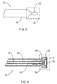
- FIG. 4 An alternative means of cooling the tip 12 is through gas expansion cooling by the Joule-Thompson effect, as is known in the art in cryoablation.
- a tip 12 configured for expansion cooling is shown in Fig. 4.
- the tip 12 has numerous small channels 34 which allow passage of a pressurized gas, such as nitrous oxide or carbon dioxide, from the outer lumen 16 into a gas expansion chamber 36. As the gas expands rapidly, it chills the thermally conductive electrode 22. The cold gas is then withdrawn from the tip 12 through the inner lumen 14.
- a liquid such as chlorodifluoromethane may be used for cooling. Liquids such as chlorodifluoromethane boil at a low temperature and cool by removing heat of vaporization through boiling.
- the exterior wall of the outer lumen 16 is the same surface as the exterior of the catheter body 18 and may include an internal metal braid to make the ice mapping and ablation catheter 10 torqueable for intracardiac manipulation.
- a cord, wire or cable 26 may be incorporated with, or inserted into, another lumen so as to make the ice mapping and ablation catheter 10 steerable.
- the cable 26 is attached to the inner lumen 14 at an attachment point 27 near the distal end of the inner lumen 14. When the surgeon tightens or pulls on the cable 26 the distal end of the inner lumen 14 moves within the outer lumen 16.
- the distal end of the inner lumen 14 presses against the distal end of the outer lumen 16 and thereby causes the distal end of the catheter 10 to bend in proportion to the force applied to the cable 26. Conversely when the cable 26 is released, the curvature of the distal end of the catheter 10 is decreased.
- a piezo-electric plastic such as polyvinylidenefluoride (trade name Kynar®)
- Kynar® polyvinylidenefluoride
- a catheter 10 is shown with an approximately three centimeter Kynar® segment 38 incorporated into a portion of the wall of the outer lumen 16 near the distal end of the catheter 10.
- the segment 38 has positive and negative electrical leads connected to an electrical power supply with wires 39. Application of an electric current of one polarity causes the segment 38 contract, which then causes the distal end of the outer lumen 16 to curve.
- Reversing the electrical polarity causes the segment 38 to expand, thereby causing the distal end of the outer lumen 16 to curve in the opposite direction.
- the movement of the outer lumen 16 causes a corresponding movement of the inner lumen 14 and permits controlled placement of the tip 12 against cardiac tissue.
- a second segment be incorporated into a wall portion of the outer lumen 16 opposite the first segment 38. Control of the distal end of the catheter 10 is achieved as with the single segment 38, except that voltages of opposite polarity are applied to the segments 38 simultaneously, thereby causing one segment 38 to contract and the other segment 38 to expand.
- An ice mapping and ablation catheter 10 having the exemplary above-referenced wall dimensions and a length of 100 centimeters, requires refrigerant pressurization of approximately 1.4x10 6 Pa (200 pounds per square inch) to produce a refrigerant flow of approximately 350 cc/min through the catheter 10.
- refrigerant inlet temperature -60 degrees Celsius
- 350 cc/min flow a 350 cc/min flow
- polyurethane wall material the temperature of the tip 12 is approximately -10 degrees Celsius when the catheter body 18 is positioned inside a human body having a nominal temperature of 37 degrees Celsius. This temperature is sufficiently cold to do ice mapping.
- the first step in the ice mapping procedure is placing the cooled tip 12 at the proposed lesion site. Because the operative procedure has several steps, the tip 12 must be stabilized at the proposed lesion site for the time necessary to ice map, to evaluate, and to ablate. A variety of configurations of the tip 12 may be employed to help secure or stabilize the catheter 10 in place against the myocardium.
- Fig. 7 depicts a pointed tip 12 or second electrode 22;
- Fig. 8 illustrates a concave tip 12 or second electrode 22 having lip or ridge 41;
- Fig. 9 depicts a bulbous tip 12 having a series of ridges 41 on the side of the tip 12.
- Fig. 10 is a cross-sectional view of the tip 12 of Fig. 9, which more clearly illustrates the configuration of the stabilizing ridges 41.
- Fig. 11 illustrates another embodiment of the catheter for ice mapping and ablation 10 which incorporates provisions for laser ablation.
- an optical fiber 40 is passed through the inner lumen 14 to a light diffuser 42 at the distal end of the catheter 10 in the center of the second electrode 22.
- the optical fiber 40 transmits light energy from a laser positioned at the proximal end of the optical fiber 40 at the proximal end of the catheter body 18. Because the laser light is highly collimated, the light diffuser 42 is used to enlarge the area ablated by the laser energy.
- the laser light may be used to heat the second electrode 22, as shown in Fig. 12, or a separate thermally conductive element, to a temperature of approximately +80 degrees Celsius for the procedure known as heat ablation.
- the ice-mapping and laser light or heat ablation procedure is similar to that for radio frequency or direct current ablation, the sole difference being the method of heat generation.
- the second electrode 22 may incorporate stabilization features as depicted in Figs. 7-10.
- Fig. 11 is shown configured with optional first and second electrodes 20 and 22 for electrocardiographic mapping, while the embodiment of Fig. 12 is not, to show the possible variety of configurations for the catheter 10. However, it is also contemplated that the catheter 10 of Fig. 12 be configured with mapping electrodes 20 and 22.
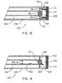
- FIG. 13 depicts a cryogenic catheter 100 which uses ball and spring valves 102 to control the pressure of a circulating cooling fluid.
- the cryogenic catheter 100 is constructed in a manner similar to the catheter for ice mapping and ablation 10 of Fig. 1, and has a first or inner lumen 104 positioned within a second or outer lumen 106.
- a liquid under pressure such as a chlorinated fluorocarbon at 10 6 Pa (150 pounds per square inch (psi)
- a liquid under pressure such as a chlorinated fluorocarbon at 10 6 Pa (150 pounds per square inch (psi)
- 10 6 Pa 150 pounds per square inch
- a micropore filter 112 fills the distal end of the inner lumen 104 to prevent any traces of liquid coolant from entering the inner lumen 104 that serves as the gas return line.
- the ball and spring valves 102 are arranged about the periphery of the inner lumen 104, and each valve 102 incorporates a helical metal spring or silicone rubber pad serving as a spring 114, pre-loaded to equal or exceed the pressure of the fluid in the outer lumen 106 (e.g., a fluid pressure of 10 6 Pa (150 psi), and a spring load of 1.25 x 10 6 Pa (180 psi)).
- the valve 102 may comprise any combination of materials which produce in a liquid tight seal.
- the ball 116 is stainless steel and the seat 118 is polytetrafluorethylene.
- the fluid pressure in the outer lumen 106 is increased until the ball 116 is displaced from its seat 118, thereby allowing pressurized liquid to enter the expansion chamber 108.
- the lower pressure in the boiling chamber 108 permits the fluid to vaporize (boil), which causes its temperature to drop and thereby cool the tip 110.
- Lowering the fluid pressure in the outer lumen 106 to a level below the spring load stops fluid flow into the boiling chamber 108. Because different liquids have different boiling points and vapor pressures, the specific choice of liquid determines the temperature to which the tip 110 is cooled and the required pre-load of the spring value.
- the cooling tip 110 that is placed in contact with body tissue to be cooled, may be fabricated from any metal such as surgical stainless steel to ensure bio-compatibility.
- any metal such as surgical stainless steel to ensure bio-compatibility.
- copper which provides superior thermal conductivity, or aluminum may be used, and may be coated with gold, silver, or titanium to preclude an adverse bio-chemical reaction by the body.
- FIG. 14 an alternative embodiment of the cryogenic catheter 100 is shown, wherein actively controlled electrically powered valves 120 replace the passive ball and spring valves 102 of Fig. 13 for fluid control.
- One such valve type is an electric solenoid valve, another is a needle valve.
- electrically controlled and powered valves 120 When electrically controlled and powered valves 120 are used, the fluid pressure is held constant within the outer lumen 106. Opening and closing of the valves 120 may be in response to a signal from a remote control unit with allows either manual or automatic temperature regulation or with temperature sensors 122 mounted within the cryogenic catheter 100.
- the temperature sensors 122 may include at least one thermocouple or thermistor, or other devices well known in the art.
- temperature sensors 122 are especially useful for monitoring tip temperature and for balancing the heat load with the liquid boil off.
- a temperature sensor 122 is located at the tip 110, in the inner lumen 104, and on the supply side of the filter 112.
- Another means of controlling the tip temperature may be achieved by controlling the pressure in the boiling chamber through active pumping or exhausting of the gas, or with in-line flow restriction. By actively pumping out or evacuating the gas from the return gas lumen, the pressure in the boiling chamber 108 is lowered. Because boiling points of liquids decrease with lowered pressure, by this means, the cryogenic liquid in the boiling chamber 108 boils at a lower temperature, thereby lowering the tip temperature further. Conversely, use of a controllable flow restriction device 124 in the exhaust lumen, depicted in Fig. 14, may raise the pressure in the boiling chamber, thereby elevating its boiling temperature and raising the tip temperature
- the inner and outer lumens 104 and 106 may be functionally reversed for ease of manufacture or to warm the return gas lumen so as to keep the catheter flexible.
- the lumens may also be incorporated in the catheter in a non-concentric or side-by-side geometry.
- the cryogenic catheter 100 may be rigid or as flexible as the catheter for ice mapping and ablation 10 depending on the desired application. When the catheter 100 is flexible, it may incorporate the steering features disclosed with respect to Figs. 5 and 6. The catheter 100 may also incorporate the position stabilization devices discussed with respect to Figs. 7, 8, 9 and 10. Furthermore, the cryogenic catheter of Figs. 13 and 14 may incorporate the ice mapping and ablation means discussed with respect to Figs. 1, 3, 4, 11 and 12.
Abstract
Description
- The invention relates to the field of catheters, and more particularly to a catheter used in cardiac procedures.
- Cardiac arrhythmias are caused by localized electrophysiologic phenomena. These are of generally two types: additional foci or reentrant circuits. Reentrant circuits can be highly localized, as in ventricular tachycardia postinfarction or AV node reentry, or can be of a grosser morphology, as in accessory pathway pathologies. Since they are localized phenomena, they can be treated surgically. The task is to remove or destroy the offending region, thereby eliminating the source of the arrhythmia.
- Current surgical therapies include: cardiotomy; open chest cryoablation; closed-chest catheter radio frequency (rf) ablation; and closed-chest direct current ablation. Radio frequency catheter ablation is becoming the therapy of choice. The greatest drawback of rf ablation is that, prior to ablation, the site of the intended cardiac lesion must be determined by conventional electrocardiographic mapping. Unfortunately, conventional mapping does not provide definitive isolation of the problem area. In a great majority of cases, more than one lesion must be made in order to effect a cure. Multiple lesions are required because the effectiveness of each of the proposed lesion sites cannot be predetermined due to the limitations of conventional electrocardiographic mapping. Often five lesions, and sometimes as many as twenty lesions may be required before a successful result is obtained. Usually only one of the lesions is actually effective; the other lesions result in unnecessarily destroyed cardiac tissue.
- Treatment of cardiac arrhythmias through selective ablation of cardiac tissue may be improved if, prior to ablation, the local electrical activity of the region can be suppressed to determine the effectiveness of the proposed lesion site in stopping the arrhythmia. Localized electrical activity may be suppressed by chilling small regions of myocardial tissue and then performing electrocardiographic mapping to evaluate the arrhythmia. This technique of cooling and mapping is called "zero-degree" or "ice" mapping. If the proposed lesion site would be effective, as determined by the ice mapping, to eliminate the arrhythmia, the site is ablated. Despite the advantages of cryoablation, it has not been the technique of choice for want of a single, easily operated device which effectively combines the functions of cryogenic cooling of cardiac tissue and tissue ablation.
- Patent document US-A-3 524 446 describes a catheter in which can be identified the characteristics set forth in the preamble of claim 1.
- The invention concerns a catheter according to Claim 1.
- The invention provides an ablation catheter which combines zero-degree or ice mapping and tissue ablation means in a single device. The invention includes a first and a second lumen for circulating a cooling fluid to the distal end of a catheter which includes an ablation device. The ablation device may be one pole of a multipole mapping electrode which conducts radio frequency energy, or direct current energy for tissue ablation. Alternatively, the ablation electrode may be replaced with an optical fiber in communication with a laser. The light energy is dispersed by a light diffuser toward a lesion site to ablate the tissue. The catheter may have an optional steering device to curve the distal end of the catheter, and the ablation device may be held in contact with the myocardial tissue with the aid of a pointed ridge.
- The catheter is insertable through an artery or vein into the heart or into a cardiac vessel and placed against the site of a proposed lesion. Cooling fluid is circulated to the tip of the catheter through the lumens, thereby cooling a localized region of cardiac tissue. The electrical activity of the heart is then measured to evaluate the effectiveness of the proposed site. If the test results indicate that a lesion would eliminate a cardiac arrhythmia, the region is ablated with either radio frequency, direct current or laser light energy.
- Yet another embodiment of the invention is a cryogenic device useful for cardiac cryosurgery, mapping, any endoscopic cryosurgery or as a cryoprobe in open surgical procedures. The invention provides a first lumen within a second lumen for circulating a pressurized refrigerant at a cooling tip. Flow control of the fluid is achieved through either a passive ball and spring device or an active, electric control valve.
- A more complete understanding of the present invention and attendant advantages and features thereof will be more readily understood by reference to the following detailed description when considered in conjunction with the accompanying drawings wherein:
- Fig. 1 is a schematic of an embodiment of the catheter of the invention for ice mapping and ablation, having mapping electrodes and a first rf ablation electrode at the distal end of the catheter;
- Fig. 2 is a cross-sectional view of a human body, showing a catheter of the invention within the heart and a second rf electrode beneath the body;
- Fig. 3 is a side view of an embodiment of the catheter for ice mapping having an electrode for direct current ablation;
- Fig. 4 is a schematic of an embodiment of the catheter for ice mapping and ablation having a tip which is cooled by gas expansion;
- Fig. 5 is a schematic of an embodiment of the invention having a movable cable to permit steering of the catheter;
- Fig. 6 is a schematic of an embodiment of the invention having a piezo-electric steering element within the catheter near the distal end;
- Fig. 7 illustrates an embodiment of a stabilization device having a point imbedded in cardiac tissue to temporarily anchor the ice mapping and ablation catheter at a desired location;
- Fig. 8 illustrates another embodiment of a stabilization device having a concave electrode or ablation tip with a ridge on its perimeter;
- Fig. 9 illustrates another embodiment of a stabilization device which incorporates a series of longitudinal ridges on the tip of the catheter;
- Fig. 10 is a cross-sectional view of the tip illustrated in Fig. 9, which more clearly illustrates the location and shape of the ridges;
- Fig. 11 is a schematic of an embodiment of the catheter of the invention with an optical fiber and light diffuser for laser ablation;
- Fig. 12 is a schematic of an embodiment of the catheter of the invention having a heat ablation tip heated by laser energy;
- Fig. 13 is a schematic of an embodiment of a cryogenic catheter for cardiac cryosurgery having a ball and spring fluid pressure control device; and
- Fig. 14 is a schematic of an embodiment of a cryogenic catheter for endoscopic cryosurgery having an electrically controlled flow control device.
-
- Fig. 1 is a schematic of an embodiment of the ice mapping and
ablation catheter 10. Thecatheter 10 has atip 12 at its distal end which is alternately used for ice-mapping and radio frequency ablation. The proximal end of thecatheter 10 is accessible to a surgeon and is connectable to a refrigerant source (not shown). The ice mapping andablation catheter 10 combines twolumens catheter body 18 to carry a refrigerant to and away from, respectively, thetip 12. The exemplary embodiment of the ice mapping andablation catheter 10, depicted in Fig. 1, has the following wall dimensions forlumens 14 and 16:outer lumen 16, 0.297 cm (0.117") Outer Diameter (O.D.) by 0.224 cm (0.088") Inner Diameter (I.D.); andinner lumen 14, 0.173 cm (0.068") O.D. by 0.152 cm (0.060") I.D. - In the embodiment shown, the
tip 12 includes afirst electrode 20, circumferentially disposed on thecatheter body 18, and asecond electrode 22, both connected to an electrical signal amplifier with wires 23. The first andsecond electrodes electrodes second electrode 22 also acts as a thermal conductor between thecatheter tip 12 and cardiac tissue when a refrigerant is passed through theinner lumen 14 to thetip 12. For radio frequency (rf) ablation, a wire 23 supplies (rf) current to thesecond electrode 22 which acts as an ablation device. - In other embodiments, additional electrodes may be added to the
tip 12 to make a multipole mapping electrode. In another embodiment, a conductive refrigerant may be used to provide the electrical connection to thefirst electrode 20, thereby obviating the need for wires 23. In yet another embodiment, the refrigerant is an electrically insulating fluid like trimethylsiloxy terminated polydimethylsiloxane, and the wires 23, free of insulation, may be located within thelumens inner lumen 14, and one wire 23 in theouter lumen 16. The combination of the insulating fluid and the insulating effect of the walls of thelumens - In all of the embodiments, the ablation surface or device on the
tip 12 is not necessarily thesecond electrode 22. The ablation device may be a separate surface which is distinguishable from thesecond electrode 22. - When the
catheter 10 is used for ablation, thesecond electrode 22 and athird electrode 24, shown in Fig. 2, are employed. Fig. 2 is a representative cross-section of a human chest cavity 25 depicting approximate locations of aheart 28,lungs 30 andspinal column 32. The patient is shown resting on a conductive plate orthird electrode 24. The ice-mapping andablation catheter 10, which is smooth enough to pass easily through blood vessels and heart valves, is shown inside theheart 28. Creation of an electrical potential difference between thesecond electrode 22 and thethird electrode 24 permits controlled ablation of cardiac tissue. Thethird electrode 24 may also be used for electrocardiographic mapping. In another embodiment of thecatheter 10, shown in Fig. 3, a reconfiguredtip 12 houses an elongatedsecond electrode 22 useful for direct current ablation. - The
catheter 10 of Fig. 1 is better understood with reference to its use in an operative procedure. Following the determination of a proposed lesion site by electrocardiographic mapping, using the first andsecond electrodes ablation catheter 10 is directed to the proposed region where lesions will be made. Following positioning of thetip 12 on the cardiac tissue, the refrigerant flow is turned on to allow a cooling fluid, such as ethyl alcohol, freon, or polydimethlsiloxane to flow from the reservoir within theinner lumen 14 to thetip 12, and then to return to the reservoir via theouter lumen 16. While the flow direction may be reversed, causing refrigerant to be introduced via theouter lumen 16 and withdrawn from theinner lumen 14, the resultant cooling of the exterior of thecatheter body 18 would unnecessarily cool blood vessels and require that the refrigerant be colder when introduced into thecatheter 10, to allow for warming of the coolant before it reaches thetip 12. In another embodiment of thecatheter 10, thecatheter body 18 may enclose a "bundle" of lumens as an alternative to the "tube-within-a-tube" configuration depicted in Fig. 1. In all of the configurations, circulation of refrigerant at thetip 12 permits controllable cooling of thetip 12 to cool the proposed lesion site. - An alternative means of cooling the
tip 12 is through gas expansion cooling by the Joule-Thompson effect, as is known in the art in cryoablation. Atip 12 configured for expansion cooling is shown in Fig. 4. Thetip 12 has numeroussmall channels 34 which allow passage of a pressurized gas, such as nitrous oxide or carbon dioxide, from theouter lumen 16 into agas expansion chamber 36. As the gas expands rapidly, it chills the thermallyconductive electrode 22. The cold gas is then withdrawn from thetip 12 through theinner lumen 14. In lieu of pressurized gas, a liquid such as chlorodifluoromethane may be used for cooling. Liquids such as chlorodifluoromethane boil at a low temperature and cool by removing heat of vaporization through boiling. - The exterior wall of the
outer lumen 16 is the same surface as the exterior of thecatheter body 18 and may include an internal metal braid to make the ice mapping andablation catheter 10 torqueable for intracardiac manipulation. To further facilitate intracardiac manipulation, a cord, wire orcable 26 may be incorporated with, or inserted into, another lumen so as to make the ice mapping andablation catheter 10 steerable. In the embodiment of Fig. 5, thecable 26 is attached to theinner lumen 14 at anattachment point 27 near the distal end of theinner lumen 14. When the surgeon tightens or pulls on thecable 26 the distal end of theinner lumen 14 moves within theouter lumen 16. As the distal end of theinner lumen 14 curves, it presses against the distal end of theouter lumen 16 and thereby causes the distal end of thecatheter 10 to bend in proportion to the force applied to thecable 26. Conversely when thecable 26 is released, the curvature of the distal end of thecatheter 10 is decreased. - It is further contemplated that a piezo-electric plastic, such as polyvinylidenefluoride (trade name Kynar®), be added to the inner or outer surface of the distal end of either the
inner lumen 14 or theouter lumen 16 to make the ice mapping andablation catheter 10 similarly steerable. Referring to Fig. 6, acatheter 10 is shown with an approximately three centimeterKynar® segment 38 incorporated into a portion of the wall of theouter lumen 16 near the distal end of thecatheter 10. Thesegment 38 has positive and negative electrical leads connected to an electrical power supply withwires 39. Application of an electric current of one polarity causes thesegment 38 contract, which then causes the distal end of theouter lumen 16 to curve. Reversing the electrical polarity causes thesegment 38 to expand, thereby causing the distal end of theouter lumen 16 to curve in the opposite direction. The movement of theouter lumen 16 causes a corresponding movement of theinner lumen 14 and permits controlled placement of thetip 12 against cardiac tissue. - It is further contemplated that a second segment be incorporated into a wall portion of the
outer lumen 16 opposite thefirst segment 38. Control of the distal end of thecatheter 10 is achieved as with thesingle segment 38, except that voltages of opposite polarity are applied to thesegments 38 simultaneously, thereby causing onesegment 38 to contract and theother segment 38 to expand. - An ice mapping and
ablation catheter 10, having the exemplary above-referenced wall dimensions and a length of 100 centimeters, requires refrigerant pressurization of approximately 1.4x10⁶ Pa (200 pounds per square inch) to produce a refrigerant flow of approximately 350 cc/min through thecatheter 10. With a refrigerant inlet temperature of -60 degrees Celsius, a 350 cc/min flow, and a polyurethane wall material, the temperature of thetip 12 is approximately -10 degrees Celsius when thecatheter body 18 is positioned inside a human body having a nominal temperature of 37 degrees Celsius. This temperature is sufficiently cold to do ice mapping. - The first step in the ice mapping procedure is placing the cooled
tip 12 at the proposed lesion site. Because the operative procedure has several steps, thetip 12 must be stabilized at the proposed lesion site for the time necessary to ice map, to evaluate, and to ablate. A variety of configurations of thetip 12 may be employed to help secure or stabilize thecatheter 10 in place against the myocardium. Fig. 7 depicts a pointedtip 12 orsecond electrode 22; Fig. 8 illustrates aconcave tip 12 orsecond electrode 22 having lip orridge 41; and Fig. 9 depicts abulbous tip 12 having a series ofridges 41 on the side of thetip 12. Fig. 10 is a cross-sectional view of thetip 12 of Fig. 9, which more clearly illustrates the configuration of the stabilizingridges 41. - When the cardiac tissue reaches approximately +5 degrees Celsius, its electrical activity is suppressed. If the proposed lesion site will be therapeutically effective when ablated, the arrhythmia will no longer be inducible once the electrical activity of the proposed site is suppressed by cooling. Having confirmed the effectiveness of the proposed site, rf ablation is performed using the
second electrode 22 and thethird electrode 24 in manner known to those skilled in the art. - Fig. 11 illustrates another embodiment of the catheter for ice mapping and
ablation 10 which incorporates provisions for laser ablation. In this embodiment anoptical fiber 40 is passed through theinner lumen 14 to alight diffuser 42 at the distal end of thecatheter 10 in the center of thesecond electrode 22. Theoptical fiber 40 transmits light energy from a laser positioned at the proximal end of theoptical fiber 40 at the proximal end of thecatheter body 18. Because the laser light is highly collimated, thelight diffuser 42 is used to enlarge the area ablated by the laser energy. Alternatively, the laser light may be used to heat thesecond electrode 22, as shown in Fig. 12, or a separate thermally conductive element, to a temperature of approximately +80 degrees Celsius for the procedure known as heat ablation. The ice-mapping and laser light or heat ablation procedure is similar to that for radio frequency or direct current ablation, the sole difference being the method of heat generation. As with rf ablation, thesecond electrode 22 may incorporate stabilization features as depicted in Figs. 7-10. - The embodiment of Fig. 11 is shown configured with optional first and
second electrodes catheter 10. However, it is also contemplated that thecatheter 10 of Fig. 12 be configured withmapping electrodes - Figures 13 and 14 depict two cryogenic catheter embodiments which use cooling for both mapping and ablation. Fig. 13 depicts a
cryogenic catheter 100 which uses ball andspring valves 102 to control the pressure of a circulating cooling fluid. Thecryogenic catheter 100 is constructed in a manner similar to the catheter for ice mapping andablation 10 of Fig. 1, and has a first orinner lumen 104 positioned within a second orouter lumen 106. In the exemplary embodiment, a liquid under pressure, such as a chlorinated fluorocarbon at 106 Pa (150 pounds per square inch (psi)), is pumped into the outer lumen, thence through ball andspring valves 102 to a boilingchamber 108 proximate ametal cooling tip 110, whereby boiling of the cryogenic fluid cools thetip 110. Amicropore filter 112 fills the distal end of theinner lumen 104 to prevent any traces of liquid coolant from entering theinner lumen 104 that serves as the gas return line. By this means boiling is confined to the boiling chamber and the cryogenic liquid does not interfere with the return gas pumping. - The ball and
spring valves 102 are arranged about the periphery of theinner lumen 104, and eachvalve 102 incorporates a helical metal spring or silicone rubber pad serving as aspring 114, pre-loaded to equal or exceed the pressure of the fluid in the outer lumen 106 (e.g., a fluid pressure of 106 Pa (150 psi), and a spring load of 1.25 x 10⁶ Pa (180 psi)). Thevalve 102 may comprise any combination of materials which produce in a liquid tight seal. In a present embodiment, theball 116 is stainless steel and theseat 118 is polytetrafluorethylene. - In order to cool the
tip 110, the fluid pressure in theouter lumen 106 is increased until theball 116 is displaced from itsseat 118, thereby allowing pressurized liquid to enter theexpansion chamber 108. The lower pressure in the boilingchamber 108 permits the fluid to vaporize (boil), which causes its temperature to drop and thereby cool thetip 110. Lowering the fluid pressure in theouter lumen 106 to a level below the spring load stops fluid flow into the boilingchamber 108. Because different liquids have different boiling points and vapor pressures, the specific choice of liquid determines the temperature to which thetip 110 is cooled and the required pre-load of the spring value. - The
cooling tip 110 that is placed in contact with body tissue to be cooled, may be fabricated from any metal such as surgical stainless steel to ensure bio-compatibility. However, copper which provides superior thermal conductivity, or aluminum may be used, and may be coated with gold, silver, or titanium to preclude an adverse bio-chemical reaction by the body. - Referring to Fig. 14, an alternative embodiment of the
cryogenic catheter 100 is shown, wherein actively controlled electricallypowered valves 120 replace the passive ball andspring valves 102 of Fig. 13 for fluid control. One such valve type is an electric solenoid valve, another is a needle valve. When electrically controlled andpowered valves 120 are used, the fluid pressure is held constant within theouter lumen 106. Opening and closing of thevalves 120 may be in response to a signal from a remote control unit with allows either manual or automatic temperature regulation or withtemperature sensors 122 mounted within thecryogenic catheter 100. Thetemperature sensors 122 may include at least one thermocouple or thermistor, or other devices well known in the art. - Due to the need for maintaining a uniform temperature at the
tip 110, as well as keeping it as cold as possible within the constraints of a given cooling and also to prevent the liquid from entirely filling the boiling chamber and preventing boiling,temperature sensors 122 are especially useful for monitoring tip temperature and for balancing the heat load with the liquid boil off. Atemperature sensor 122 is located at thetip 110, in theinner lumen 104, and on the supply side of thefilter 112. - Another means of controlling the tip temperature may be achieved by controlling the pressure in the boiling chamber through active pumping or exhausting of the gas, or with in-line flow restriction. By actively pumping out or evacuating the gas from the return gas lumen, the pressure in the boiling
chamber 108 is lowered. Because boiling points of liquids decrease with lowered pressure, by this means, the cryogenic liquid in the boilingchamber 108 boils at a lower temperature, thereby lowering the tip temperature further. Conversely, use of a controllableflow restriction device 124 in the exhaust lumen, depicted in Fig. 14, may raise the pressure in the boiling chamber, thereby elevating its boiling temperature and raising the tip temperature - As previously discussed with respect to the
catheter 10 of Fig. 1, the inner andouter lumens - The
cryogenic catheter 100 may be rigid or as flexible as the catheter for ice mapping andablation 10 depending on the desired application. When thecatheter 100 is flexible, it may incorporate the steering features disclosed with respect to Figs. 5 and 6. Thecatheter 100 may also incorporate the position stabilization devices discussed with respect to Figs. 7, 8, 9 and 10. Furthermore, the cryogenic catheter of Figs. 13 and 14 may incorporate the ice mapping and ablation means discussed with respect to Figs. 1, 3, 4, 11 and 12. - A variety of modifications and variations of the present invention are possible in light of the above teachings. It is therefore to be understood that, within the scope of the appended claims, the present invention may be practiced otherwise than as specifically described hereinabove.
Claims (32)
- A catheter (10) for ice mapping and ablation comprising :characterized in that:an open proximal end adapted for connection to a reservoir containing a cooling fluid;a closed, thermally conductive distal end (12);a first lumen (14) conducting said cooling fluid from said proximal end to said distal end, to chill cardiac tissue for suppression of localised electrical activity,a second lumen (16) permitting return of said cooling fluid from said distal end to said proximal end;said catheter (10) comprises non-cryogenic ablation means located at said distal end of said catheter for ablating myocardial tissue andan electrocardiographic mapping means comprising at least one mapping electrode located near said distal end of said catheter.
- The catheter of claim 1, wherein said non-cryogenic ablation means comprises a first radio frequency electrode (20) integral with said catheter co-operative with a second radio frequency electrode (22) adapted to be separated from said first electrode by tissue to be ablated, said first radio frequency electrode being operative to transmit electric current from said first radio frequency electrode to said second radio frequency electrode.
- The catheter of claim 1, wherein said non-cryogenic ablation means comprises an optical fiber (40) extending from said proximal end to said distal end (12), said distal end of said optical fiber configured to permit passage of laser energy from said optical fiber axially outward from said distal end of said catheter through a light diffuser (42).
- The catheter of claim 1, wherein said non-cryogenic ablation means comprises an optical fiber (40) extending from said proximal end to said distal end (12) of said catheter, said distal end comprising a heatable surface, said heatable surface (22) heated by laser energy from said optical fiber.
- The catheter according to any preceding claim, wherein said cooling fluid is a liquid.
- The catheter of claim 5, wherein said liquid boils at a low temperature and cools by removing heat of vaporization through boiling.
- The catheter of claim 6, wherein said liquid is chlorodifluoromethane.
- The catheter of any of claims 1 to 5, further comprising :an expansion chamber (36) located substantially at said distal end of said catheter, andwherein said cooling fluid is a pressurized gas which becomes cold upon expansion in an expansion chamber (36).
- The catheter according to any preceding claim, further comprising a position stabilization means including at least one surface irregularity (41) on said distal end (12) to prevent slippage of said distal end when said distal end is in contact with a body tissue.
- The catheter of claim 9, wherein said position stabilization means is a pointed conductive surface (12).
- The catheter according to any preceding claim, further comprising a catheter steering means (26; 38).
- The catheter of claim 1,said catheter further comprising a first electrode (20) located near said distal end of said catheter, wherein said first electrode is a first pole of said electrocardiographic mapping means;a second electrode (22) located at said distal end of said catheter, wherein said second electrode is a second pole of said electrocardiographic mapping means and a radio frequency ablation means operative to transmit electric current from said first radio frequency electrode to a second radio frequency electrode by tissue including tissue to be ablated;a position stabilization means (41) including at least one surface section on said distal end adapted to prevent slippage of said distal end when said distal end is in contact with said tissue to be ablated; anda steering means (26; 38) to position said radio frequency ablation means.
- The catheter of claim 11 or 12, wherein said catheter steering means comprises at least one flexible wire (26) having a first end attached to said first lumen (14) near said distal end of said catheter, and a second end detached from said catheter, accessible from said proximal end of said catheter, wherein increasing or reducing tension on said at least one flexible wire causes said distal end of said catheter to move.
- The catheter of claim 11 or 12, wherein said catheter steering means comprises at least one segment (38) of piezo-electric material anchored to a portion of said distal end (12) of said catheter, wherein application of an electric voltage of a first polarity to said segment causes contraction of said segment and application of an electric voltage of a second polarity to said segment causes expansion of said segment, thereby causing said distal end of
said catheter to move as a function of polarity and strength of said electric voltage. - The catheter according to any of claims 1 to 7, for cryogenic operations, further comprising :a valve (102) associated with one of said first and second lumens (respectively 14, 16), said valve regulating flow of a cooling fluid between said first lumen and said second lumen, wherein said valve comprises a ball biased against a ball seat (118) with a biasing means (114), said ball preventing flow of said cooling fluid through a passage within said ball seat until said cooling fluid exerts sufficient pressure against said ball to overcome bias forces imparted thereon, thereby displacing said ball from said ball seat; anda chamber (108) for permitting said cooling fluid to boil, cool, and thereby chill a tissue cooling surface located proximate said chamber, said cooling fluid introduced into said chamber through said valve by way of said first lumen and exhausted from said chamber via said second lumen.
- The catheter of any of claims 1 to 7, adapted for cryogenic operations, wherein said first lumen (104) is concentric with said second lumen (106), said first lumen concentric with said second lumen being sufficiently flexible and sufficiently narrow to be inserted into and travel through a cardiac blood vessel without injuring said cardiac blood vessel;at least one control valve (120) for regulating flow of said cooling fluid from said distal end of said first lumen into a boiling chamber (108) that connects said distal end of said first lumen and said distal end of said second lumen, said boiling chamber permitting boiling of said cooling fluid into a gaseous state, wherein said control valve has an open and a closed state, for permitting said cooling fluid to pass from said first lumen into said boiling chamber when said at least one control valve is in said open state, said at least one control valve being responsive to and electric control signal; anda plurality of temperature sensors (122) for producing said electric control signal, including a temperature sensor located within said second lumen; anda cooling surface proximate said boiling chamber, wherein said cooling surface is a thermal conductor (fig. 14).
- The catheter of claim 16, further comprising a micropore filter (112) positioned within said second lumen (116) to prevent said cooling fluid in a liquid state from exiting said proximal end of said second lumen.
- The catheter of claim 17, wherein said micropore filter (112) is a plug of glass wool that substantially fills said distal end of said second lumen (116).
- The catheter of claim 18, wherien said micropore filter (112) is sponge that substantially fills said distal end of said second lumen (116).
- The catheter of any of claims 1 to 7, adapted for cryogenic operations, wherein said first lumen (104) is concentric with said second lumen (106); and further comprising :at least one control valve (102) for regulating flow of said cooling fluid from said distal end of said first lumen into a boiling chamber (108) that connects said distal end of said first lumen and said distal end of said second lumen, said boiling chamber permitting boiling of said cooling fluid into a gaseous state, said at least one control valve comprising :a ball seat (118);a ball (116), matable with said ball seat for forming a fluid tight seal, said ball seat having a passage therein for permitting said cooling fluid to pass from said first lumen into said boiling chamber when said ball is displaced; anda biasing means (114), for biasing said ball toward said ball seat, said biasing means causing said ball to mate with said ball seat until said cooling fluid is pressurized to a predetermined pressure level; anda cooling surface proximate said boiling chamber, wherein said cooling surface is a thermal conductor.
- The catheter of claim 20, wherein said biasing means is a spring (114).
- The catheter of claim 20, wherein said biasing means is a compressible pad.
- The catheter of any of claims 16 to 19, wherein said at least one control valve comprises a needle valve.
- The catheter of any of claims 16 to 19, wherein said at least one control valve comprises a solenoid valve (120).
- The catheter of any of claims 16 to 19, or 23 to 24, further comprising said plurality of temperature sensors (122) forming at least one thermocouple.
- The catheter of any of claims 16 to 19, or 23 to 24, wherein said plurality of temperature sensors comprises at least one thermistor (122).
- The catheter according to any of claims 15 to 26, further comprising a position stabilization means including at least one surface irregularity (41) on said distal end (12) to prevent slippage of said distal end when said distal end is in contact with a body tissue.
- The catheter of claim 27, wherein said position stabilization means is a pointed conductive surface (12).
- The catheter according to any of claims 15 to 28 further comprising a catheter steering means (26; 38).
- The catheter of any of claims 15 to 29,said catheter further comprising a first electrode (20) located near said distal end of said catheter, wherein said first electrode is a first pole of said electrocardiographic mapping means;a second electrode (22) located at said distal end of said catheter, wherein said second electrode is a second pole of said electrocardiographic mapping means and a radio frequency ablation means operative to transmit electric current from said first radio frequency electrode to a second radio frequency electrode by tissue including tissue to be ablated;a position stabilization means (41) including at least one surface section on said distal end adapted to prevent slippage of said distal end when said distal end is in contact with said tissue to be ablated; anda steering means (26; 38) to position said radio frequency ablation means.
- The catheter of claim 29 or 30, wherein said catheter steering means comprises at least one flexible wire (26) having a first end attached to said first lumen (14) near said distal end of said catheter, and a second end detached from said catheter, accessible from said proximal end of said catheter, wherein increasing or reducing tension on said at least one flexible wire causes said distal end of said catheter to move.
- The catheter of claim 29 or 30, wherein said catheter steering means comprises at least one segment (38) of piezo-electric material anchored to a portion of said distal end (12) of said catheter, wherein application of an electric voltage of a first polarity to said segment causes contraction of said segment and application of an electric voltage of a second polarity to said segment causes expansion of said segment, thereby causing said distal end of said catheter to move as a function of polarity and strength of said electric voltage.
Applications Claiming Priority (5)
| Application Number | Priority Date | Filing Date | Title |
|---|---|---|---|
| US870495 | 1992-04-16 | ||
| US07/870,495 US5281213A (en) | 1992-04-16 | 1992-04-16 | Catheter for ice mapping and ablation |
| US898142 | 1992-06-15 | ||
| US07/898,142 US5281215A (en) | 1992-04-16 | 1992-06-15 | Cryogenic catheter |
| PCT/US1993/003612 WO1993020769A1 (en) | 1992-04-16 | 1993-04-16 | Cryogenic catheter |
Publications (3)
| Publication Number | Publication Date |
|---|---|
| EP0680284A4 EP0680284A4 (en) | 1995-06-20 |
| EP0680284A1 EP0680284A1 (en) | 1995-11-08 |
| EP0680284B1 true EP0680284B1 (en) | 2002-10-16 |
Family
ID=27128159
Family Applications (1)
| Application Number | Title | Priority Date | Filing Date |
|---|---|---|---|
| EP93912285A Expired - Lifetime EP0680284B1 (en) | 1992-04-16 | 1993-04-16 | Cryogenic catheter |
Country Status (6)
| Country | Link |
|---|---|
| US (1) | US5281215A (en) |
| EP (1) | EP0680284B1 (en) |
| JP (1) | JP3209276B2 (en) |
| CA (1) | CA2118011C (en) |
| DE (1) | DE69332414T2 (en) |
| WO (1) | WO1993020769A1 (en) |
Families Citing this family (396)
| Publication number | Priority date | Publication date | Assignee | Title |
|---|---|---|---|---|
| US5588432A (en) * | 1988-03-21 | 1996-12-31 | Boston Scientific Corporation | Catheters for imaging, sensing electrical potentials, and ablating tissue |
| US5624392A (en) * | 1990-05-11 | 1997-04-29 | Saab; Mark A. | Heat transfer catheters and methods of making and using same |
| WO1993020768A1 (en) * | 1992-04-13 | 1993-10-28 | Ep Technologies, Inc. | Steerable microwave antenna systems for cardiac ablation |
| US5423807A (en) * | 1992-04-16 | 1995-06-13 | Implemed, Inc. | Cryogenic mapping and ablation catheter |
| US6623516B2 (en) * | 1992-08-13 | 2003-09-23 | Mark A. Saab | Method for changing the temperature of a selected body region |
| US5676693A (en) * | 1992-11-13 | 1997-10-14 | Scimed Life Systems, Inc. | Electrophysiology device |
| US6110168A (en) * | 1993-02-10 | 2000-08-29 | Radiant Medical, Inc. | Method and apparatus for controlling a patient's body temperature by in situ blood temperature modifications |
| US6849083B2 (en) * | 1993-02-10 | 2005-02-01 | Radiant Medical, Inc. | Method and apparatus for controlling a patients's body temperature by in situ blood temperature modification |
| US5837003A (en) * | 1993-02-10 | 1998-11-17 | Radiant Medical, Inc. | Method and apparatus for controlling a patient's body temperature by in situ blood temperature modification |
| US6620188B1 (en) | 1998-08-24 | 2003-09-16 | Radiant Medical, Inc. | Methods and apparatus for regional and whole body temperature modification |
| US6161543A (en) | 1993-02-22 | 2000-12-19 | Epicor, Inc. | Methods of epicardial ablation for creating a lesion around the pulmonary veins |
| US5433717A (en) * | 1993-03-23 | 1995-07-18 | The Regents Of The University Of California | Magnetic resonance imaging assisted cryosurgery |
| CA2164860C (en) * | 1993-06-10 | 2005-09-06 | Mir A. Imran | Transurethral radio frequency ablation apparatus |
| US5840031A (en) * | 1993-07-01 | 1998-11-24 | Boston Scientific Corporation | Catheters for imaging, sensing electrical potentials and ablating tissue |
| CA2165829A1 (en) * | 1993-07-01 | 1995-01-19 | John E. Abele | Imaging, electrical potential sensing, and ablation catheters |
| US5630837A (en) * | 1993-07-01 | 1997-05-20 | Boston Scientific Corporation | Acoustic ablation |
| NL9301851A (en) * | 1993-10-26 | 1995-05-16 | Cordis Europ | Cryo-ablation catheter. |
| US6099524A (en) * | 1994-01-28 | 2000-08-08 | Cardiac Pacemakers, Inc. | Electrophysiological mapping and ablation catheter and method |
| US5967976A (en) * | 1994-08-19 | 1999-10-19 | Novoste Corporation | Apparatus and methods for procedures related to the electrophysiology of the heart |
| US5529067A (en) * | 1994-08-19 | 1996-06-25 | Novoste Corporation | Methods for procedures related to the electrophysiology of the heart |
| US5957917A (en) * | 1995-01-20 | 1999-09-28 | Miravant Systems, Inc. | Transluminal hyperthermia catheter and method for use |
| US6409722B1 (en) | 1998-07-07 | 2002-06-25 | Medtronic, Inc. | Apparatus and method for creating, maintaining, and controlling a virtual electrode used for the ablation of tissue |
| US5897553A (en) | 1995-11-02 | 1999-04-27 | Medtronic, Inc. | Ball point fluid-assisted electrocautery device |
| US5741248A (en) * | 1995-06-07 | 1998-04-21 | Temple University-Of The Commonwealth System Of Higher Education | Fluorochemical liquid augmented cryosurgery |
| US5746736A (en) * | 1995-08-09 | 1998-05-05 | Lumedics, Ltd. | Cryogenic laser lithotripsy with enhanced light absorption |
| US5706823A (en) * | 1995-08-18 | 1998-01-13 | Quinton Instrument Company | Electrophysiology filtering system |
| US5758505C1 (en) * | 1995-10-12 | 2001-10-30 | Cryogen Inc | Precooling system for joule-thomson probe |
| US5787715A (en) * | 1995-10-12 | 1998-08-04 | Cryogen, Inc. | Mixed gas refrigeration method |
| US6530234B1 (en) | 1995-10-12 | 2003-03-11 | Cryogen, Inc. | Precooling system for Joule-Thomson probe |
| US5901783A (en) * | 1995-10-12 | 1999-05-11 | Croyogen, Inc. | Cryogenic heat exchanger |
| US6151901A (en) * | 1995-10-12 | 2000-11-28 | Cryogen, Inc. | Miniature mixed gas refrigeration system |
| US5733280A (en) * | 1995-11-15 | 1998-03-31 | Avitall; Boaz | Cryogenic epicardial mapping and ablation |
| NL1003024C2 (en) * | 1996-05-03 | 1997-11-06 | Tjong Hauw Sie | Stimulus conduction blocking instrument. |
| US6805128B1 (en) | 1996-10-22 | 2004-10-19 | Epicor Medical, Inc. | Apparatus and method for ablating tissue |
| US6311692B1 (en) | 1996-10-22 | 2001-11-06 | Epicor, Inc. | Apparatus and method for diagnosis and therapy of electrophysiological disease |
| US6719755B2 (en) | 1996-10-22 | 2004-04-13 | Epicor Medical, Inc. | Methods and devices for ablation |
| US7052493B2 (en) * | 1996-10-22 | 2006-05-30 | Epicor Medical, Inc. | Methods and devices for ablation |
| US6840936B2 (en) | 1996-10-22 | 2005-01-11 | Epicor Medical, Inc. | Methods and devices for ablation |
| US6237605B1 (en) | 1996-10-22 | 2001-05-29 | Epicor, Inc. | Methods of epicardial ablation |
| NL1004655C2 (en) * | 1996-11-29 | 1998-06-03 | Cordis Europ | Ablation catheter comprising hose-shaped basic body with proximal and distal ends |
| US6270494B1 (en) | 1996-12-26 | 2001-08-07 | Cryogen, Inc. | Stretchable cryoprobe sheath |
| US5910104A (en) | 1996-12-26 | 1999-06-08 | Cryogen, Inc. | Cryosurgical probe with disposable sheath |
| US5899898A (en) * | 1997-02-27 | 1999-05-04 | Cryocath Technologies Inc. | Cryosurgical linear ablation |
| US6602247B2 (en) | 1997-02-27 | 2003-08-05 | Cryocath Technologies Inc. | Apparatus and method for performing a treatment on a selected tissue region |
| US6669689B2 (en) | 1997-02-27 | 2003-12-30 | Cryocath Technologies Inc. | Cryosurgical catheter |
| WO2000032126A1 (en) | 1997-02-27 | 2000-06-08 | Cryocath Technologies Inc. | Cryosurgical catheter |
| US6235019B1 (en) | 1997-02-27 | 2001-05-22 | Cryocath Technologies, Inc. | Cryosurgical catheter |
| US7591814B2 (en) | 1997-02-27 | 2009-09-22 | Cryocath Technologies Inc. | Extended treatment zone catheter |
| US7220257B1 (en) | 2000-07-25 | 2007-05-22 | Scimed Life Systems, Inc. | Cryotreatment device and method |
| US5868735A (en) | 1997-03-06 | 1999-02-09 | Scimed Life Systems, Inc. | Cryoplasty device and method |
| US5846235A (en) * | 1997-04-14 | 1998-12-08 | Johns Hopkins University | Endoscopic cryospray device |
| US5971983A (en) | 1997-05-09 | 1999-10-26 | The Regents Of The University Of California | Tissue ablation device and method of use |
| US6024740A (en) | 1997-07-08 | 2000-02-15 | The Regents Of The University Of California | Circumferential ablation device assembly |
| US6012457A (en) | 1997-07-08 | 2000-01-11 | The Regents Of The University Of California | Device and method for forming a circumferential conduction block in a pulmonary vein |
| US6027499A (en) * | 1997-05-23 | 2000-02-22 | Fiber-Tech Medical, Inc. (Assignee Of Jennifer B. Cartledge) | Method and apparatus for cryogenic spray ablation of gastrointestinal mucosa |
| US6312426B1 (en) * | 1997-05-30 | 2001-11-06 | Sherwood Services Ag | Method and system for performing plate type radiofrequency ablation |
| US6652515B1 (en) * | 1997-07-08 | 2003-11-25 | Atrionix, Inc. | Tissue ablation device assembly and method for electrically isolating a pulmonary vein ostium from an atrial wall |
| US6500174B1 (en) * | 1997-07-08 | 2002-12-31 | Atrionix, Inc. | Circumferential ablation device assembly and methods of use and manufacture providing an ablative circumferential band along an expandable member |
| US6117101A (en) * | 1997-07-08 | 2000-09-12 | The Regents Of The University Of California | Circumferential ablation device assembly |
| US6997925B2 (en) * | 1997-07-08 | 2006-02-14 | Atrionx, Inc. | Tissue ablation device assembly and method for electrically isolating a pulmonary vein ostium from an atrial wall |
| US6869431B2 (en) | 1997-07-08 | 2005-03-22 | Atrionix, Inc. | Medical device with sensor cooperating with expandable member |
| US6245064B1 (en) | 1997-07-08 | 2001-06-12 | Atrionix, Inc. | Circumferential ablation device assembly |
| US6096037A (en) * | 1997-07-29 | 2000-08-01 | Medtronic, Inc. | Tissue sealing electrosurgery device and methods of sealing tissue |
| EP1014873A4 (en) | 1997-09-22 | 2003-07-09 | Ethicon Inc | Cryosurgical system and method |
| US8709007B2 (en) | 1997-10-15 | 2014-04-29 | St. Jude Medical, Atrial Fibrillation Division, Inc. | Devices and methods for ablating cardiac tissue |
| US5885276A (en) * | 1997-12-02 | 1999-03-23 | Galil Medical Ltd. | Method and device for transmyocardial cryo revascularization |
| US6491039B1 (en) | 1998-01-23 | 2002-12-10 | Innercool Therapies, Inc. | Medical procedure |
| US6325818B1 (en) | 1999-10-07 | 2001-12-04 | Innercool Therapies, Inc. | Inflatable cooling apparatus for selective organ hypothermia |
| US6254626B1 (en) | 1998-03-24 | 2001-07-03 | Innercool Therapies, Inc. | Articulation device for selective organ cooling apparatus |
| US6251129B1 (en) | 1998-03-24 | 2001-06-26 | Innercool Therapies, Inc. | Method for low temperature thrombolysis and low temperature thrombolytic agent with selective organ temperature control |
| US7371254B2 (en) * | 1998-01-23 | 2008-05-13 | Innercool Therapies, Inc. | Medical procedure |
| US6383210B1 (en) * | 2000-06-02 | 2002-05-07 | Innercool Therapies, Inc. | Method for determining the effective thermal mass of a body or organ using cooling catheter |
| US6238428B1 (en) | 1998-01-23 | 2001-05-29 | Innercool Therapies, Inc. | Selective organ cooling apparatus and method employing turbulence-inducing element with curved terminations |
| US6251130B1 (en) | 1998-03-24 | 2001-06-26 | Innercool Therapies, Inc. | Device for applications of selective organ cooling |
| US6558412B2 (en) * | 1998-01-23 | 2003-05-06 | Innercool Therapies, Inc. | Selective organ hypothermia method and apparatus |
| US6585752B2 (en) * | 1998-06-23 | 2003-07-01 | Innercool Therapies, Inc. | Fever regulation method and apparatus |
| US6719779B2 (en) * | 2000-11-07 | 2004-04-13 | Innercool Therapies, Inc. | Circulation set for temperature-controlled catheter and method of using the same |
| US6843800B1 (en) | 1998-01-23 | 2005-01-18 | Innercool Therapies, Inc. | Patient temperature regulation method and apparatus |
| US6991645B2 (en) | 1998-01-23 | 2006-01-31 | Innercool Therapies, Inc. | Patient temperature regulation method and apparatus |
| US6051019A (en) | 1998-01-23 | 2000-04-18 | Del Mar Medical Technologies, Inc. | Selective organ hypothermia method and apparatus |
| US6261312B1 (en) | 1998-06-23 | 2001-07-17 | Innercool Therapies, Inc. | Inflatable catheter for selective organ heating and cooling and method of using the same |
| US6464716B1 (en) * | 1998-01-23 | 2002-10-15 | Innercool Therapies, Inc. | Selective organ cooling apparatus and method |
| US6379378B1 (en) | 2000-03-03 | 2002-04-30 | Innercool Therapies, Inc. | Lumen design for catheter |
| US6491716B2 (en) | 1998-03-24 | 2002-12-10 | Innercool Therapies, Inc. | Method and device for applications of selective organ cooling |
| US6471717B1 (en) * | 1998-03-24 | 2002-10-29 | Innercool Therapies, Inc. | Selective organ cooling apparatus and method |
| US6245095B1 (en) | 1998-03-24 | 2001-06-12 | Innercool Therapies, Inc. | Method and apparatus for location and temperature specific drug action such as thrombolysis |
| US6231595B1 (en) * | 1998-03-31 | 2001-05-15 | Innercool Therapies, Inc. | Circulating fluid hypothermia method and apparatus |
| US6096068A (en) | 1998-01-23 | 2000-08-01 | Innercool Therapies, Inc. | Selective organ cooling catheter and method of using the same |
| US6312452B1 (en) | 1998-01-23 | 2001-11-06 | Innercool Therapies, Inc. | Selective organ cooling catheter with guidewire apparatus and temperature-monitoring device |
| US6042559A (en) * | 1998-02-24 | 2000-03-28 | Innercool Therapies, Inc. | Insulated catheter for selective organ perfusion |
| US6224624B1 (en) | 1998-03-24 | 2001-05-01 | Innercool Therapies, Inc. | Selective organ cooling apparatus and method |
| US6599312B2 (en) | 1998-03-24 | 2003-07-29 | Innercool Therapies, Inc. | Isolated selective organ cooling apparatus |
| US6551349B2 (en) | 1998-03-24 | 2003-04-22 | Innercool Therapies, Inc. | Selective organ cooling apparatus |
| US6576002B2 (en) | 1998-03-24 | 2003-06-10 | Innercool Therapies, Inc. | Isolated selective organ cooling method and apparatus |
| US6602276B2 (en) * | 1998-03-31 | 2003-08-05 | Innercool Therapies, Inc. | Method and device for performing cooling- or cryo-therapies for, e.g., angioplasty with reduced restenosis or pulmonary vein cell necrosis to inhibit atrial fibrillation |
| US7001378B2 (en) * | 1998-03-31 | 2006-02-21 | Innercool Therapies, Inc. | Method and device for performing cooling or cryo-therapies, for, e.g., angioplasty with reduced restenosis or pulmonary vein cell necrosis to inhibit atrial fibrillation employing tissue protection |
| US6685732B2 (en) | 1998-03-31 | 2004-02-03 | Innercool Therapies, Inc. | Method and device for performing cooling- or cryo-therapies for, e.g., angioplasty with reduced restenosis or pulmonary vein cell necrosis to inhibit atrial fibrillation employing microporous balloon |
| US6905494B2 (en) * | 1998-03-31 | 2005-06-14 | Innercool Therapies, Inc. | Method and device for performing cooling- or cryo-therapies for, e.g., angioplasty with reduced restenosis or pulmonary vein cell necrosis to inhibit atrial fibrillation employing tissue protection |
| US7291144B2 (en) | 1998-03-31 | 2007-11-06 | Innercool Therapies, Inc. | Method and device for performing cooling- or cryo-therapies for, e.g., angioplasty with reduced restenosis or pulmonary vein cell necrosis to inhibit atrial fibrillation |
| US6106518A (en) | 1998-04-09 | 2000-08-22 | Cryocath Technologies, Inc. | Variable geometry tip for a cryosurgical ablation device |
| US6368304B1 (en) | 1999-02-19 | 2002-04-09 | Alsius Corporation | Central venous catheter with heat exchange membrane |
| US6589271B1 (en) | 1998-04-21 | 2003-07-08 | Alsius Corporations | Indwelling heat exchange catheter |
| US6716236B1 (en) | 1998-04-21 | 2004-04-06 | Alsius Corporation | Intravascular catheter with heat exchange element having inner inflation element and methods of use |
| US6338727B1 (en) | 1998-08-13 | 2002-01-15 | Alsius Corporation | Indwelling heat exchange catheter and method of using same |
| US6419643B1 (en) | 1998-04-21 | 2002-07-16 | Alsius Corporation | Central venous catheter with heat exchange properties |
| US6126684A (en) | 1998-04-21 | 2000-10-03 | The Regents Of The University Of California | Indwelling heat exchange catheter and method of using same |
| US6458150B1 (en) | 1999-02-19 | 2002-10-01 | Alsius Corporation | Method and apparatus for patient temperature control |
| US8128595B2 (en) | 1998-04-21 | 2012-03-06 | Zoll Circulation, Inc. | Method for a central venous line catheter having a temperature control system |
| GB2336781B (en) * | 1998-04-30 | 2001-03-07 | Spembly Medical Ltd | Cryosurgical apparatus |
| IL124549A0 (en) * | 1998-05-19 | 1998-12-06 | Benny Gaber | Thermoablation probe |
| US6527767B2 (en) * | 1998-05-20 | 2003-03-04 | New England Medical Center | Cardiac ablation system and method for treatment of cardiac arrhythmias and transmyocardial revascularization |
| US6241722B1 (en) | 1998-06-17 | 2001-06-05 | Cryogen, Inc. | Cryogenic device, system and method of using same |
| US6706039B2 (en) | 1998-07-07 | 2004-03-16 | Medtronic, Inc. | Method and apparatus for creating a bi-polar virtual electrode used for the ablation of tissue |
| US6537272B2 (en) * | 1998-07-07 | 2003-03-25 | Medtronic, Inc. | Apparatus and method for creating, maintaining, and controlling a virtual electrode used for the ablation of tissue |
| US6537248B2 (en) * | 1998-07-07 | 2003-03-25 | Medtronic, Inc. | Helical needle apparatus for creating a virtual electrode used for the ablation of tissue |
| US6319248B1 (en) | 1998-07-29 | 2001-11-20 | Cryocath Technologies, Inc. | Spray catheter |
| US6450990B1 (en) | 1998-08-13 | 2002-09-17 | Alsius Corporation | Catheter with multiple heating/cooling fibers employing fiber spreading features |
| US8308719B2 (en) * | 1998-09-21 | 2012-11-13 | St. Jude Medical, Atrial Fibrillation Division, Inc. | Apparatus and method for ablating tissue |
| US6245062B1 (en) * | 1998-10-23 | 2001-06-12 | Afx, Inc. | Directional reflector shield assembly for a microwave ablation instrument |
| US6607502B1 (en) | 1998-11-25 | 2003-08-19 | Atrionix, Inc. | Apparatus and method incorporating an ultrasound transducer onto a delivery member |
| US6575933B1 (en) | 1998-11-30 | 2003-06-10 | Cryocath Technologies Inc. | Mechanical support for an expandable membrane |
| US6241718B1 (en) | 1998-11-30 | 2001-06-05 | Cryocath Technologies, Inc. | Method for inhibiting restenosis |
| US20050228367A1 (en) * | 1999-01-25 | 2005-10-13 | Marwan Abboud | Leak detection system for catheter based medical device |
| US6869440B2 (en) * | 1999-02-09 | 2005-03-22 | Innercool Therapies, Inc. | Method and apparatus for patient temperature control employing administration of anti-shivering agents |
| US6830581B2 (en) * | 1999-02-09 | 2004-12-14 | Innercool Therspies, Inc. | Method and device for patient temperature control employing optimized rewarming |
| US6582398B1 (en) | 1999-02-19 | 2003-06-24 | Alsius Corporation | Method of managing patient temperature with a heat exchange catheter |
| US6299599B1 (en) | 1999-02-19 | 2001-10-09 | Alsius Corporation | Dual balloon central venous line catheter temperature control system |
| US6405080B1 (en) | 1999-03-11 | 2002-06-11 | Alsius Corporation | Method and system for treating cardiac arrest |
| AT409584B (en) * | 2000-02-23 | 2002-09-25 | Nikolai Dr Korpan | CONNECTION ARRANGEMENT BETWEEN THE COAXIAL LINES FOR DIRECT AND BACKFLOW OF THE CRYOGENIC MEDIUM |
| US6270476B1 (en) | 1999-04-23 | 2001-08-07 | Cryocath Technologies, Inc. | Catheter |
| US7226446B1 (en) | 1999-05-04 | 2007-06-05 | Dinesh Mody | Surgical microwave ablation assembly |
| US6165207A (en) * | 1999-05-27 | 2000-12-26 | Alsius Corporation | Method of selectively shaping hollow fibers of heat exchange catheter |
| US6277113B1 (en) | 1999-05-28 | 2001-08-21 | Afx, Inc. | Monopole tip for ablation catheter and methods for using same |
| US6471694B1 (en) | 2000-08-09 | 2002-10-29 | Cryogen, Inc. | Control system for cryosurgery |
| US6626899B2 (en) * | 1999-06-25 | 2003-09-30 | Nidus Medical, Llc | Apparatus and methods for treating tissue |
| US7004936B2 (en) * | 2000-08-09 | 2006-02-28 | Cryocor, Inc. | Refrigeration source for a cryoablation catheter |
| US6270493B1 (en) | 1999-07-19 | 2001-08-07 | Cryocath Technologies, Inc. | Cryoablation structure |
| US20070282324A1 (en) * | 1999-07-19 | 2007-12-06 | Matthias Vaska | Apparatus and method for diagnosis and therapy of electrophysiological disease |
| EP1207788A4 (en) | 1999-07-19 | 2009-12-09 | St Jude Medical Atrial Fibrill | Apparatus and method for ablating tissue |
| US6287326B1 (en) | 1999-08-02 | 2001-09-11 | Alsius Corporation | Catheter with coiled multi-lumen heat transfer extension |
| US6447474B1 (en) | 1999-09-15 | 2002-09-10 | Alsius Corporation | Automatic fever abatement system |
| US7097641B1 (en) | 1999-12-09 | 2006-08-29 | Cryocath Technologies Inc. | Catheter with cryogenic and heating ablation |
| US7033352B1 (en) | 2000-01-18 | 2006-04-25 | Afx, Inc. | Flexible ablation instrument |
| US6692450B1 (en) * | 2000-01-19 | 2004-02-17 | Medtronic Xomed, Inc. | Focused ultrasound ablation devices having selectively actuatable ultrasound emitting elements and methods of using the same |
| US6595934B1 (en) * | 2000-01-19 | 2003-07-22 | Medtronic Xomed, Inc. | Methods of skin rejuvenation using high intensity focused ultrasound to form an ablated tissue area containing a plurality of lesions |
| US7706882B2 (en) * | 2000-01-19 | 2010-04-27 | Medtronic, Inc. | Methods of using high intensity focused ultrasound to form an ablated tissue area |
| US6447443B1 (en) * | 2001-01-13 | 2002-09-10 | Medtronic, Inc. | Method for organ positioning and stabilization |
| US8221402B2 (en) * | 2000-01-19 | 2012-07-17 | Medtronic, Inc. | Method for guiding a medical device |
| US6551274B2 (en) | 2000-02-29 | 2003-04-22 | Biosense Webster, Inc. | Cryoablation catheter with an expandable cooling chamber |
| US6497703B1 (en) | 2000-03-02 | 2002-12-24 | Biosense Webster | Cryoablation catheter for long lesion ablations |
| US6702810B2 (en) * | 2000-03-06 | 2004-03-09 | Tissuelink Medical Inc. | Fluid delivery system and controller for electrosurgical devices |
| US8048070B2 (en) | 2000-03-06 | 2011-11-01 | Salient Surgical Technologies, Inc. | Fluid-assisted medical devices, systems and methods |
| US8083736B2 (en) * | 2000-03-06 | 2011-12-27 | Salient Surgical Technologies, Inc. | Fluid-assisted medical devices, systems and methods |
| US6953461B2 (en) | 2002-05-16 | 2005-10-11 | Tissuelink Medical, Inc. | Fluid-assisted medical devices, systems and methods |
| US7811282B2 (en) * | 2000-03-06 | 2010-10-12 | Salient Surgical Technologies, Inc. | Fluid-assisted electrosurgical devices, electrosurgical unit with pump and methods of use thereof |
| US6689131B2 (en) * | 2001-03-08 | 2004-02-10 | Tissuelink Medical, Inc. | Electrosurgical device having a tissue reduction sensor |
| US6558385B1 (en) | 2000-09-22 | 2003-05-06 | Tissuelink Medical, Inc. | Fluid-assisted medical device |
| US6849072B2 (en) * | 2000-04-07 | 2005-02-01 | The General Hospital Corporation | Methods and apparatus for thermally affecting tissue |
| US6673068B1 (en) * | 2000-04-12 | 2004-01-06 | Afx, Inc. | Electrode arrangement for use in a medical instrument |
| US6546935B2 (en) | 2000-04-27 | 2003-04-15 | Atricure, Inc. | Method for transmural ablation |
| US6932811B2 (en) * | 2000-04-27 | 2005-08-23 | Atricure, Inc. | Transmural ablation device with integral EKG sensor |
| US20020107514A1 (en) | 2000-04-27 | 2002-08-08 | Hooven Michael D. | Transmural ablation device with parallel jaws |
| US6905498B2 (en) | 2000-04-27 | 2005-06-14 | Atricure Inc. | Transmural ablation device with EKG sensor and pacing electrode |
| US6488680B1 (en) | 2000-04-27 | 2002-12-03 | Medtronic, Inc. | Variable length electrodes for delivery of irrigated ablation |
| WO2001082811A1 (en) * | 2000-04-27 | 2001-11-08 | Medtronic, Inc. | System and method for assessing transmurality of ablation lesions |
| EP1278471B1 (en) * | 2000-04-27 | 2005-06-15 | Medtronic, Inc. | Vibration sensitive ablation apparatus |
| US6514250B1 (en) * | 2000-04-27 | 2003-02-04 | Medtronic, Inc. | Suction stabilized epicardial ablation devices |
| EP1296598B1 (en) * | 2000-05-16 | 2007-11-14 | Atrionix, Inc. | Apparatus incorporating an ultrasound transducer on a delivery member |
| DE20009426U1 (en) * | 2000-05-26 | 2001-10-31 | Desinger Kai | Surgical instrument |
| AU6682401A (en) | 2000-06-13 | 2001-12-24 | Atrionix Inc | Surgical ablation probe for forming a circumferential lesion |
| US6726708B2 (en) * | 2000-06-14 | 2004-04-27 | Innercool Therapies, Inc. | Therapeutic heating and cooling via temperature management of a colon-inserted balloon |
| US8256430B2 (en) | 2001-06-15 | 2012-09-04 | Monteris Medical, Inc. | Hyperthermia treatment and probe therefor |
| US6537271B1 (en) * | 2000-07-06 | 2003-03-25 | Cryogen, Inc. | Balloon cryogenic catheter |
| US6551309B1 (en) * | 2000-09-14 | 2003-04-22 | Cryoflex, Inc. | Dual action cryoprobe and methods of using the same |
| US6926669B1 (en) * | 2000-10-10 | 2005-08-09 | Medtronic, Inc. | Heart wall ablation/mapping catheter and method |
| US20020068929A1 (en) * | 2000-10-24 | 2002-06-06 | Roni Zvuloni | Apparatus and method for compressing a gas, and cryosurgery system and method utilizing same |
| US6706037B2 (en) * | 2000-10-24 | 2004-03-16 | Galil Medical Ltd. | Multiple cryoprobe apparatus and method |
| US20020087151A1 (en) * | 2000-12-29 | 2002-07-04 | Afx, Inc. | Tissue ablation apparatus with a sliding ablation instrument and method |
| US7628780B2 (en) * | 2001-01-13 | 2009-12-08 | Medtronic, Inc. | Devices and methods for interstitial injection of biologic agents into tissue |
| US20040138621A1 (en) | 2003-01-14 | 2004-07-15 | Jahns Scott E. | Devices and methods for interstitial injection of biologic agents into tissue |
| US7740623B2 (en) * | 2001-01-13 | 2010-06-22 | Medtronic, Inc. | Devices and methods for interstitial injection of biologic agents into tissue |
| US6666858B2 (en) * | 2001-04-12 | 2003-12-23 | Scimed Life Systems, Inc. | Cryo balloon for atrial ablation |
| US7959626B2 (en) | 2001-04-26 | 2011-06-14 | Medtronic, Inc. | Transmural ablation systems and methods |
| US6761715B2 (en) | 2001-04-26 | 2004-07-13 | Ronald J. Carroll | Method and device for neurocryo analgesia and anesthesia |
| US6699240B2 (en) | 2001-04-26 | 2004-03-02 | Medtronic, Inc. | Method and apparatus for tissue ablation |
| US6648883B2 (en) * | 2001-04-26 | 2003-11-18 | Medtronic, Inc. | Ablation system and method of use |
| US6663627B2 (en) | 2001-04-26 | 2003-12-16 | Medtronic, Inc. | Ablation system and method of use |
| US6807968B2 (en) * | 2001-04-26 | 2004-10-26 | Medtronic, Inc. | Method and system for treatment of atrial tachyarrhythmias |
| US7250048B2 (en) | 2001-04-26 | 2007-07-31 | Medtronic, Inc. | Ablation system and method of use |
| US6585728B2 (en) | 2001-05-25 | 2003-07-01 | Biosense Webster, Inc. | Cryoablation catheter with an improved gas expansion chamber |
| WO2003015672A1 (en) * | 2001-08-15 | 2003-02-27 | Innercool Therapies, Inc. | Method and apparatus for patient temperature control employing administration of anti-shivering |
| US20040249372A1 (en) * | 2001-09-26 | 2004-12-09 | Leonilda Capuano | Method for treatment of aneurysms |
| US6736809B2 (en) | 2001-09-26 | 2004-05-18 | Cryocath Technologies Inc. | Method and device for treatment of aneurysms |
| US7912554B2 (en) * | 2001-09-26 | 2011-03-22 | Medtronic Cryocath Lp | Method for treatment of aneurysms |
| US6589234B2 (en) | 2001-09-27 | 2003-07-08 | Cryocath Technologies Inc. | Cryogenic medical device with high pressure resistance tip |
| US6579287B2 (en) | 2001-10-09 | 2003-06-17 | Cryocath Technologies Inc. | Cryosurgical ablation device having sequential injection and method therefor |
| US6547785B1 (en) | 2001-10-23 | 2003-04-15 | Biosense Webster, Inc. | Cryoablation catheter for long lesion ablations |
| US20030088240A1 (en) * | 2001-11-02 | 2003-05-08 | Vahid Saadat | Methods and apparatus for cryo-therapy |
| US6572640B1 (en) | 2001-11-21 | 2003-06-03 | Alsius Corporation | Method and apparatus for cardiopulmonary bypass patient temperature control |
| US6656175B2 (en) * | 2001-12-11 | 2003-12-02 | Medtronic, Inc. | Method and system for treatment of atrial tachyarrhythmias |
| AU2002357166A1 (en) * | 2001-12-12 | 2003-06-23 | Tissuelink Medical, Inc. | Fluid-assisted medical devices, systems and methods |
| US6709431B2 (en) | 2001-12-18 | 2004-03-23 | Scimed Life Systems, Inc. | Cryo-temperature monitoring |
| US6949094B2 (en) * | 2001-12-19 | 2005-09-27 | Ran Yaron | Miniature refrigeration system for cryothermal ablation catheter |
| US7099717B2 (en) | 2002-01-03 | 2006-08-29 | Afx Inc. | Catheter having improved steering |
| AU2003209287A1 (en) | 2002-01-15 | 2003-07-30 | The Regents Of The University Of California | System and method providing directional ultrasound therapy to skeletal joints |
| WO2003061496A1 (en) | 2002-01-16 | 2003-07-31 | Lehmann John W | Cryosurgical catheter |
| US7819826B2 (en) * | 2002-01-23 | 2010-10-26 | The Regents Of The University Of California | Implantable thermal treatment method and apparatus |
| US20080275439A1 (en) * | 2002-01-25 | 2008-11-06 | David Francischelli | Cardiac ablation and electrical interface system and instrument |
| US7967816B2 (en) * | 2002-01-25 | 2011-06-28 | Medtronic, Inc. | Fluid-assisted electrosurgical instrument with shapeable electrode |
| US6827715B2 (en) * | 2002-01-25 | 2004-12-07 | Medtronic, Inc. | System and method of performing an electrosurgical procedure |
| US7192427B2 (en) * | 2002-02-19 | 2007-03-20 | Afx, Inc. | Apparatus and method for assessing transmurality of a tissue ablation |
| US20050075629A1 (en) * | 2002-02-19 | 2005-04-07 | Afx, Inc. | Apparatus and method for assessing tissue ablation transmurality |
| US6989009B2 (en) * | 2002-04-19 | 2006-01-24 | Scimed Life Systems, Inc. | Cryo balloon |
| US7294143B2 (en) * | 2002-05-16 | 2007-11-13 | Medtronic, Inc. | Device and method for ablation of cardiac tissue |
| US7118566B2 (en) | 2002-05-16 | 2006-10-10 | Medtronic, Inc. | Device and method for needle-less interstitial injection of fluid for ablation of cardiac tissue |
| US20040024392A1 (en) * | 2002-08-05 | 2004-02-05 | Lewis James D. | Apparatus and method for cryosurgery |
| US20040034344A1 (en) * | 2002-08-16 | 2004-02-19 | Eric Ryba | Tip pressure monitoring for cryoablation catheters |
| US6955673B2 (en) * | 2002-08-16 | 2005-10-18 | Cryocor, Inc. | Heat transfer segment for a cryoablation catheter |
| US6929639B2 (en) * | 2002-08-30 | 2005-08-16 | Scimed Life Systems, Inc. | Cryo ablation coil |
| US6786202B2 (en) * | 2002-09-24 | 2004-09-07 | Caterpillar Inc | Hydraulic pump circuit |
| US8361067B2 (en) | 2002-09-30 | 2013-01-29 | Relievant Medsystems, Inc. | Methods of therapeutically heating a vertebral body to treat back pain |
| US6907884B2 (en) | 2002-09-30 | 2005-06-21 | Depay Acromed, Inc. | Method of straddling an intraosseous nerve |
| US7258690B2 (en) | 2003-03-28 | 2007-08-21 | Relievant Medsystems, Inc. | Windowed thermal ablation probe |
| US7291161B2 (en) | 2002-10-02 | 2007-11-06 | Atricure, Inc. | Articulated clamping member |
| WO2004039416A2 (en) | 2002-10-29 | 2004-05-13 | Tissuelink Medical, Inc. | Fluid-assisted electrosurgical scissors and methods |
| US7083620B2 (en) * | 2002-10-30 | 2006-08-01 | Medtronic, Inc. | Electrosurgical hemostat |
| US6918869B2 (en) | 2002-12-02 | 2005-07-19 | Scimed Life Systems | System for administering a combination of therapies to a body lumen |
| US7278984B2 (en) * | 2002-12-31 | 2007-10-09 | Alsius Corporation | System and method for controlling rate of heat exchange with patient |
| US20040167466A1 (en) * | 2003-02-21 | 2004-08-26 | Drasler William J. | Delivering cooled fluid to sites inside the body |
| US20040167467A1 (en) * | 2003-02-21 | 2004-08-26 | Kent Harrison | Delivering cooled fluid to sites inside the body |
| US7300453B2 (en) * | 2003-02-24 | 2007-11-27 | Innercool Therapies, Inc. | System and method for inducing hypothermia with control and determination of catheter pressure |
| US7938828B2 (en) * | 2003-03-28 | 2011-05-10 | Boston Scientific Scimed, Inc. | Cooled ablation catheter |
| US20040204705A1 (en) | 2003-04-10 | 2004-10-14 | Scimed Life Systems, Inc. | Cryotreatment devices and methods of forming conduction blocks |
| US7118591B2 (en) * | 2003-04-17 | 2006-10-10 | The University Of Chicago | Heat transfer probe |
| US7288092B2 (en) | 2003-04-23 | 2007-10-30 | Atricure, Inc. | Method and apparatus for ablating cardiac tissue with guide facility |
| KR100466866B1 (en) * | 2003-04-24 | 2005-01-24 | 전명기 | Electrode for radiofrequency tissue ablation |
| US7497857B2 (en) * | 2003-04-29 | 2009-03-03 | Medtronic, Inc. | Endocardial dispersive electrode for use with a monopolar RF ablation pen |
| DE10332564A1 (en) * | 2003-07-11 | 2005-01-27 | Celon Ag Medical Instruments | Surgical device for coagulation or ablation of tissue, comprising hollow shaft accommodating cooling duct and two ring-shaped electrodes |
| US7311703B2 (en) * | 2003-07-18 | 2007-12-25 | Vivant Medical, Inc. | Devices and methods for cooling microwave antennas |
| US6981382B2 (en) * | 2003-07-24 | 2006-01-03 | Cryocor, Inc. | Distal end for cryoablation catheters |
| US20050027289A1 (en) * | 2003-07-31 | 2005-02-03 | Thomas Castellano | Cryoablation systems and methods |
| DE10342709A1 (en) * | 2003-09-11 | 2005-04-21 | Biotronik Gmbh & Co Kg | catheter |
| US20050059448A1 (en) * | 2003-09-11 | 2005-03-17 | Scott Sims | Method and apparatus for playing card game |
| US20050059963A1 (en) * | 2003-09-12 | 2005-03-17 | Scimed Life Systems, Inc. | Systems and method for creating transmural lesions |
| US7326195B2 (en) * | 2003-11-18 | 2008-02-05 | Boston Scientific Scimed, Inc. | Targeted cooling of tissue within a body |
| US7727232B1 (en) | 2004-02-04 | 2010-06-01 | Salient Surgical Technologies, Inc. | Fluid-assisted medical devices and methods |
| US7070594B2 (en) * | 2004-02-10 | 2006-07-04 | Cryocor, Inc. | System and method for assessing ice ball formation during a cryoablation procedure |
| US20050187545A1 (en) * | 2004-02-20 | 2005-08-25 | Hooven Michael D. | Magnetic catheter ablation device and method |
| US7157213B2 (en) * | 2004-03-01 | 2007-01-02 | Think Laboratory Co., Ltd. | Developer agent for positive type photosensitive compound |
| US20050198972A1 (en) * | 2004-03-10 | 2005-09-15 | Lentz David J. | Pressure-temperature control for a cryoablation catheter system |
| US8491636B2 (en) | 2004-03-23 | 2013-07-23 | Medtronic Cryopath LP | Method and apparatus for inflating and deflating balloon catheters |
| US7727228B2 (en) | 2004-03-23 | 2010-06-01 | Medtronic Cryocath Lp | Method and apparatus for inflating and deflating balloon catheters |
| US7530980B2 (en) * | 2004-04-14 | 2009-05-12 | Atricure, Inc | Bipolar transmural ablation method and apparatus |
| US8333764B2 (en) * | 2004-05-12 | 2012-12-18 | Medtronic, Inc. | Device and method for determining tissue thickness and creating cardiac ablation lesions |
| ES2308505T3 (en) * | 2004-05-14 | 2008-12-01 | Medtronic, Inc. | ULTRASONIC ENERGY USE SYSTEM FOCUSED ON HIGH INTENS IDAD TO FORM A CUTTED FABRIC AREA. |
| US20060036302A1 (en) * | 2004-05-28 | 2006-02-16 | Kasza Kenneth E | Methods of inducing protective hypothermia of organs |
| WO2005120374A1 (en) * | 2004-06-02 | 2005-12-22 | Medtronic, Inc. | Compound bipolar ablation device and method |
| WO2005120375A2 (en) * | 2004-06-02 | 2005-12-22 | Medtronic, Inc. | Loop ablation apparatus and method |
| WO2005120376A2 (en) * | 2004-06-02 | 2005-12-22 | Medtronic, Inc. | Ablation device with jaws |
| ATE516762T1 (en) * | 2004-06-02 | 2011-08-15 | Medtronic Inc | ABLATION AND STAPLE INSTRUMENT |
| US20100145331A1 (en) * | 2004-06-02 | 2010-06-10 | Chrisitian Steven C | Loop Ablation Apparatus and Method |
| US8409219B2 (en) * | 2004-06-18 | 2013-04-02 | Medtronic, Inc. | Method and system for placement of electrical lead inside heart |
| EP1768575B1 (en) * | 2004-06-18 | 2019-01-16 | Medtronic, Inc. | Devices for occlusion of an atrial appendage |
| US8663245B2 (en) | 2004-06-18 | 2014-03-04 | Medtronic, Inc. | Device for occlusion of a left atrial appendage |
| US8926635B2 (en) * | 2004-06-18 | 2015-01-06 | Medtronic, Inc. | Methods and devices for occlusion of an atrial appendage |
| US7156840B2 (en) * | 2004-06-29 | 2007-01-02 | Cryocor, Inc. | Pressure monitor for cryoablation catheter |
| US7357797B2 (en) * | 2004-06-30 | 2008-04-15 | Cryocor, Inc. | System and method for varying return pressure to control tip temperature of a cryoablation catheter |
| US7163535B2 (en) * | 2004-06-30 | 2007-01-16 | Cryocor, Inc. | System for detecting leaks and occlusions in a cryoablation catheter |
| GB0416713D0 (en) | 2004-07-27 | 2004-09-01 | Bioelf Ltd | Catheter, apparatus for creating a linear ablation and a method of ablating tissue |
| US20060025840A1 (en) * | 2004-08-02 | 2006-02-02 | Martin Willard | Cooling tissue inside the body |
| US20060136023A1 (en) * | 2004-08-26 | 2006-06-22 | Dobak John D Iii | Method and apparatus for patient temperature control employing administration of anti-shivering agents |
| US7134543B2 (en) * | 2004-09-22 | 2006-11-14 | Frito-Lay North America, Inc. | Containment apparatus for multi-pass ovens |
| US20060161232A1 (en) * | 2005-01-18 | 2006-07-20 | Kasza, Oras and Son to The University of Chicago | Phase-change particulate ice slurry coolant medical delivery tubing and insertion devices |
| US7789846B2 (en) * | 2005-01-25 | 2010-09-07 | Thermopeutix, Inc. | System and methods for selective thermal treatment |
| US8206345B2 (en) * | 2005-03-07 | 2012-06-26 | Medtronic Cryocath Lp | Fluid control system for a medical device |
| US7674256B2 (en) | 2005-03-17 | 2010-03-09 | Boston Scientific Scimed, Inc. | Treating internal body tissue |
| US7918848B2 (en) | 2005-03-25 | 2011-04-05 | Maquet Cardiovascular, Llc | Tissue welding and cutting apparatus and method |
| US8197472B2 (en) | 2005-03-25 | 2012-06-12 | Maquet Cardiovascular, Llc | Tissue welding and cutting apparatus and method |
| US7713266B2 (en) * | 2005-05-20 | 2010-05-11 | Myoscience, Inc. | Subdermal cryogenic remodeling of muscles, nerves, connective tissue, and/or adipose tissue (fat) |
| US20060270900A1 (en) * | 2005-05-26 | 2006-11-30 | Chin Albert K | Apparatus and methods for performing ablation |
| US8932208B2 (en) * | 2005-05-26 | 2015-01-13 | Maquet Cardiovascular Llc | Apparatus and methods for performing minimally-invasive surgical procedures |
| US7951182B2 (en) | 2005-07-14 | 2011-05-31 | Zoll Circulation, Inc. | System and method for leak detection in external cooling pad |
| US7389653B2 (en) * | 2005-09-15 | 2008-06-24 | The University Of Chicago | Medical ice slurry production device |
| US20070185479A1 (en) * | 2006-02-06 | 2007-08-09 | Liming Lau | Methods and devices for performing ablation and assessing efficacy thereof |
| US20070185477A1 (en) * | 2006-02-07 | 2007-08-09 | Hooven Michael D | Removable Cryogenic Probe Appliance |
| KR101330755B1 (en) * | 2006-02-22 | 2013-11-18 | 커스텀 메디컬 애플리케이션즈, 아이엔씨. | Ablation instruments and related methods |
| US20070225697A1 (en) * | 2006-03-23 | 2007-09-27 | Ketan Shroff | Apparatus and methods for cardiac ablation |
| US20080039746A1 (en) | 2006-05-25 | 2008-02-14 | Medtronic, Inc. | Methods of using high intensity focused ultrasound to form an ablated tissue area containing a plurality of lesions |
| US7425211B2 (en) * | 2006-08-03 | 2008-09-16 | Arbel Medical Ltd. | Cryogenic probe for treating enlarged volume of tissue |
| US20080039727A1 (en) * | 2006-08-08 | 2008-02-14 | Eilaz Babaev | Ablative Cardiac Catheter System |
| US20090221955A1 (en) * | 2006-08-08 | 2009-09-03 | Bacoustics, Llc | Ablative ultrasonic-cryogenic methods |
| US20080039879A1 (en) * | 2006-08-09 | 2008-02-14 | Chin Albert K | Devices and methods for atrial appendage exclusion |
| US20080140061A1 (en) * | 2006-09-08 | 2008-06-12 | Arbel Medical Ltd. | Method And Device For Combined Treatment |
| US20080208181A1 (en) * | 2007-01-19 | 2008-08-28 | Arbel Medical Ltd. | Thermally Insulated Needles For Dermatological Applications |
| US20080312644A1 (en) * | 2007-06-14 | 2008-12-18 | Boston Scientific Scimed, Inc. | Cryogenic balloon ablation instruments and systems |
| US20100162730A1 (en) * | 2007-06-14 | 2010-07-01 | Arbel Medical Ltd. | Siphon for delivery of liquid cryogen from dewar flask |
| US20100324546A1 (en) * | 2007-07-09 | 2010-12-23 | Alexander Levin | Cryosheath |
| US8380299B2 (en) * | 2007-07-30 | 2013-02-19 | Nuvue Therapeutics, Inc. | Fluid flowing device and method for tissue diagnosis or therapy |
| WO2009045265A1 (en) | 2007-10-05 | 2009-04-09 | Maquet Cardiovascular, Llc | Devices and methods for minimally-invasive surgical procedures |
| WO2009066292A1 (en) * | 2007-11-21 | 2009-05-28 | Arbel Medical Ltd. | Pumping unit for delivery of liquid medium from a vessel |
| US8353907B2 (en) | 2007-12-21 | 2013-01-15 | Atricure, Inc. | Ablation device with internally cooled electrodes |
| US8998892B2 (en) | 2007-12-21 | 2015-04-07 | Atricure, Inc. | Ablation device with cooled electrodes and methods of use |
| EP2227174B1 (en) * | 2007-12-28 | 2019-05-01 | Salient Surgical Technologies, Inc. | Fluid-assisted electrosurgical device |
| WO2009090647A2 (en) * | 2008-01-15 | 2009-07-23 | Arbel Medical Ltd. | Cryosurgical instrument insulating system |
| US20090209986A1 (en) * | 2008-02-15 | 2009-08-20 | Stewart Michael C | Devices, Tools and Methods for Atrial Appendage Exclusion |
| EP2303168A1 (en) | 2008-04-16 | 2011-04-06 | Arbel Medical Ltd. | Cryosurgical instrument with enhanced heat exchange |
| US8814850B2 (en) * | 2008-04-24 | 2014-08-26 | Cryomedix, Llc | Method and system for cryoablation treatment |
| US8821488B2 (en) * | 2008-05-13 | 2014-09-02 | Medtronic, Inc. | Tissue lesion evaluation |
| US9050069B2 (en) | 2008-05-16 | 2015-06-09 | Medtronic Cryocath Lp | Thermocouple-controlled catheter cooling system |
| US9968396B2 (en) | 2008-05-27 | 2018-05-15 | Maquet Cardiovascular Llc | Surgical instrument and method |
| US9402680B2 (en) | 2008-05-27 | 2016-08-02 | Maquet Cardiovasular, Llc | Surgical instrument and method |
| US8728092B2 (en) | 2008-08-14 | 2014-05-20 | Monteris Medical Corporation | Stereotactic drive system |
| AU2009296474B2 (en) | 2008-09-26 | 2015-07-02 | Relievant Medsystems, Inc. | Systems and methods for navigating an instrument through bone |
| US10028753B2 (en) | 2008-09-26 | 2018-07-24 | Relievant Medsystems, Inc. | Spine treatment kits |
| US20100281917A1 (en) * | 2008-11-05 | 2010-11-11 | Alexander Levin | Apparatus and Method for Condensing Contaminants for a Cryogenic System |
| AU2009330149A1 (en) * | 2008-12-23 | 2011-06-23 | Cryomedix Llc | Isotherm-based tissue ablation control system and method |
| US9254168B2 (en) * | 2009-02-02 | 2016-02-09 | Medtronic Advanced Energy Llc | Electro-thermotherapy of tissue using penetrating microelectrode array |
| US7967814B2 (en) | 2009-02-05 | 2011-06-28 | Icecure Medical Ltd. | Cryoprobe with vibrating mechanism |
| JP5592409B2 (en) | 2009-02-23 | 2014-09-17 | サリエント・サージカル・テクノロジーズ・インコーポレーテッド | Fluid-assisted electrosurgical device and method of use thereof |
| WO2010105158A1 (en) * | 2009-03-12 | 2010-09-16 | Icecure Medical Ltd. | Combined cryotherapy and brachytherapy device and method |
| US8915908B2 (en) * | 2009-03-20 | 2014-12-23 | Atricure, Inc. | Cryogenic probe |
| DE102009018291A1 (en) * | 2009-04-21 | 2010-10-28 | Erbe Elektromedizin Gmbh | Cryosurgical instrument |
| EP2421459A1 (en) * | 2009-04-22 | 2012-02-29 | Nuvue Therapeutics, Inc. | Fluid flowing device and method for tissue diagnosis or therapy |
| US20100305439A1 (en) * | 2009-05-27 | 2010-12-02 | Eyal Shai | Device and Method for Three-Dimensional Guidance and Three-Dimensional Monitoring of Cryoablation |
| US9955858B2 (en) | 2009-08-21 | 2018-05-01 | Maquet Cardiovascular Llc | Surgical instrument and method for use |
| EP2475320B1 (en) | 2009-09-08 | 2018-02-21 | Salient Surgical Technologies, Inc. | Cartridge assembly for electrosurgical devices and corresponding electrosurgical unit |
| US20110144637A1 (en) | 2009-12-11 | 2011-06-16 | Medtronic Cryocath Lp | Vein Occlusion Devices and Methods for Catheter-Based Ablation |
| US9592090B2 (en) | 2010-03-11 | 2017-03-14 | Medtronic Advanced Energy Llc | Bipolar electrosurgical cutter with position insensitive return electrode contact |
| US7967815B1 (en) | 2010-03-25 | 2011-06-28 | Icecure Medical Ltd. | Cryosurgical instrument with enhanced heat transfer |
| US7938822B1 (en) | 2010-05-12 | 2011-05-10 | Icecure Medical Ltd. | Heating and cooling of cryosurgical instrument using a single cryogen |
| US20110295249A1 (en) * | 2010-05-28 | 2011-12-01 | Salient Surgical Technologies, Inc. | Fluid-Assisted Electrosurgical Devices, and Methods of Manufacture Thereof |
| US8080005B1 (en) | 2010-06-10 | 2011-12-20 | Icecure Medical Ltd. | Closed loop cryosurgical pressure and flow regulated system |
| US9138289B2 (en) | 2010-06-28 | 2015-09-22 | Medtronic Advanced Energy Llc | Electrode sheath for electrosurgical device |
| US8906012B2 (en) | 2010-06-30 | 2014-12-09 | Medtronic Advanced Energy Llc | Electrosurgical devices with wire electrode |
| US8920417B2 (en) | 2010-06-30 | 2014-12-30 | Medtronic Advanced Energy Llc | Electrosurgical devices and methods of use thereof |
| US20120065630A1 (en) * | 2010-09-15 | 2012-03-15 | Nir Berzak | Cryosurgical instrument for treating large volume of tissue |
| US9023040B2 (en) | 2010-10-26 | 2015-05-05 | Medtronic Advanced Energy Llc | Electrosurgical cutting devices |
| US20120109117A1 (en) * | 2010-10-28 | 2012-05-03 | Adam Harp | Cryogenic probe with swivel |
| MX341823B (en) | 2011-02-01 | 2016-09-05 | Channel Medsystems Inc | Methods and apparatus for cyrogenic treatment of a body cavity or lumen. |
| US9427281B2 (en) | 2011-03-11 | 2016-08-30 | Medtronic Advanced Energy Llc | Bronchoscope-compatible catheter provided with electrosurgical device |
| US9439707B2 (en) | 2011-03-25 | 2016-09-13 | Medtronic Cryocath Lp | Spray nozzle design for a catheter |
| US9283110B2 (en) | 2011-09-20 | 2016-03-15 | Zoll Circulation, Inc. | Patient temperature control catheter with outer sleeve cooled by inner sleeve |
| US9259348B2 (en) | 2011-09-28 | 2016-02-16 | Zoll Circulation, Inc. | Transatrial patient temperature control catheter |
| US10045881B2 (en) | 2011-09-28 | 2018-08-14 | Zoll Circulation, Inc. | Patient temperature control catheter with helical heat exchange paths |
| US8888832B2 (en) | 2011-09-28 | 2014-11-18 | Zoll Circulation, Inc. | System and method for doubled use of patient temperature control catheter |
| US9314370B2 (en) | 2011-09-28 | 2016-04-19 | Zoll Circulation, Inc. | Self-centering patient temperature control catheter |
| US9750565B2 (en) | 2011-09-30 | 2017-09-05 | Medtronic Advanced Energy Llc | Electrosurgical balloons |
| US8870864B2 (en) | 2011-10-28 | 2014-10-28 | Medtronic Advanced Energy Llc | Single instrument electrosurgery apparatus and its method of use |
| US9314588B2 (en) | 2011-10-28 | 2016-04-19 | Medtronic Cryocath Lp | Systems and methods for variable injection flow |
| US10390877B2 (en) | 2011-12-30 | 2019-08-27 | Relievant Medsystems, Inc. | Systems and methods for treating back pain |
| CA2861116A1 (en) * | 2012-01-13 | 2013-07-18 | Myoscience, Inc. | Cryogenic probe filtration system |
| US9226792B2 (en) | 2012-06-12 | 2016-01-05 | Medtronic Advanced Energy Llc | Debridement device and method |
| CN104602638B (en) | 2012-06-27 | 2017-12-19 | 曼特瑞斯医药有限责任公司 | System for influenceing to treat tissue |
| US10588691B2 (en) | 2012-09-12 | 2020-03-17 | Relievant Medsystems, Inc. | Radiofrequency ablation of tissue within a vertebral body |
| US9433528B2 (en) | 2012-09-28 | 2016-09-06 | Zoll Circulation, Inc. | Intravascular heat exchange catheter with rib cage-like coolant path |
| US9241827B2 (en) | 2012-09-28 | 2016-01-26 | Zoll Circulation, Inc. | Intravascular heat exchange catheter with multiple spaced apart discrete coolant loops |
| US9717625B2 (en) | 2012-09-28 | 2017-08-01 | Zoll Circulation, Inc. | Intravascular heat exchange catheter with non-round coiled coolant path |
| US9801756B2 (en) | 2012-09-28 | 2017-10-31 | Zoll Circulation, Inc. | Intravascular heat exchange catheter and system with RFID coupling |
| US11234760B2 (en) | 2012-10-05 | 2022-02-01 | Medtronic Advanced Energy Llc | Electrosurgical device for cutting and removing tissue |
| CA3093398C (en) | 2012-11-05 | 2022-05-24 | Relievant Medsystems, Inc. | Systems and methods for creating curved paths through bone and modulating nerves within the bone |
| US9724151B2 (en) | 2013-08-08 | 2017-08-08 | Relievant Medsystems, Inc. | Modulating nerves within bone using bone fasteners |
| US10314647B2 (en) | 2013-12-23 | 2019-06-11 | Medtronic Advanced Energy Llc | Electrosurgical cutting instrument |
| US9474644B2 (en) | 2014-02-07 | 2016-10-25 | Zoll Circulation, Inc. | Heat exchange system for patient temperature control with multiple coolant chambers for multiple heat exchange modalities |
| US10500088B2 (en) | 2014-02-14 | 2019-12-10 | Zoll Circulation, Inc. | Patient heat exchange system with two and only two fluid loops |
| US10792185B2 (en) | 2014-02-14 | 2020-10-06 | Zoll Circulation, Inc. | Fluid cassette with polymeric membranes and integral inlet and outlet tubes for patient heat exchange system |
| US11033424B2 (en) | 2014-02-14 | 2021-06-15 | Zoll Circulation, Inc. | Fluid cassette with tensioned polymeric membranes for patient heat exchange system |
| US10813686B2 (en) | 2014-02-26 | 2020-10-27 | Medtronic Advanced Energy Llc | Electrosurgical cutting instrument |
| WO2015143025A1 (en) | 2014-03-18 | 2015-09-24 | Monteris Medical Corporation | Image-guided therapy of a tissue |
| US10675113B2 (en) | 2014-03-18 | 2020-06-09 | Monteris Medical Corporation | Automated therapy of a three-dimensional tissue region |
| US20150265353A1 (en) | 2014-03-18 | 2015-09-24 | Monteris Medical Corporation | Image-guided therapy of a tissue |
| US11419656B2 (en) * | 2014-04-04 | 2022-08-23 | Cpsi Holdings Llc | Thermal regulation catheter system |
| US10610279B2 (en) | 2014-04-10 | 2020-04-07 | Channel Medsystems, Inc. | Apparatus and methods for regulating cryogenic treatment |
| US10194978B2 (en) | 2014-06-13 | 2019-02-05 | Medtronic Cryocath Lp | Supporting catheter for use for phrenic nerve pacing |
| US9974599B2 (en) | 2014-08-15 | 2018-05-22 | Medtronic Ps Medical, Inc. | Multipurpose electrosurgical device |
| US10646666B2 (en) * | 2014-08-27 | 2020-05-12 | Tva Medical, Inc. | Cryolipolysis devices and methods therefor |
| US9784263B2 (en) | 2014-11-06 | 2017-10-10 | Zoll Circulation, Inc. | Heat exchange system for patient temperature control with easy loading high performance peristaltic pump |
| US11359620B2 (en) | 2015-04-01 | 2022-06-14 | Zoll Circulation, Inc. | Heat exchange system for patient temperature control with easy loading high performance peristaltic pump |
| EP3209235B1 (en) * | 2015-01-28 | 2019-06-26 | St. Jude Medical, Cardiology Division, Inc. | Thermal mapping catheter |
| US10188456B2 (en) | 2015-02-18 | 2019-01-29 | Medtronic Xomed, Inc. | Electrode assembly for RF energy enabled tissue debridement device |
| US10376302B2 (en) | 2015-02-18 | 2019-08-13 | Medtronic Xomed, Inc. | Rotating electrical connector for RF energy enabled tissue debridement device |
| KR20170117440A (en) | 2015-02-18 | 2017-10-23 | 메드트로닉 좀드 인코퍼레이티드 | Tissue ablation devices that can use RF energy |
| US10537465B2 (en) | 2015-03-31 | 2020-01-21 | Zoll Circulation, Inc. | Cold plate design in heat exchanger for intravascular temperature management catheter and/or heat exchange pad |
| US11213423B2 (en) | 2015-03-31 | 2022-01-04 | Zoll Circulation, Inc. | Proximal mounting of temperature sensor in intravascular temperature management catheter |
| US10327830B2 (en) | 2015-04-01 | 2019-06-25 | Monteris Medical Corporation | Cryotherapy, thermal therapy, temperature modulation therapy, and probe apparatus therefor |
| US10022265B2 (en) | 2015-04-01 | 2018-07-17 | Zoll Circulation, Inc. | Working fluid cassette with hinged plenum or enclosure for interfacing heat exchanger with intravascular temperature management catheter |
| US11389227B2 (en) | 2015-08-20 | 2022-07-19 | Medtronic Advanced Energy Llc | Electrosurgical device with multivariate control |
| US11051875B2 (en) | 2015-08-24 | 2021-07-06 | Medtronic Advanced Energy Llc | Multipurpose electrosurgical device |
| US10716612B2 (en) | 2015-12-18 | 2020-07-21 | Medtronic Advanced Energy Llc | Electrosurgical device with multiple monopolar electrode assembly |
| US11090100B2 (en) | 2016-07-05 | 2021-08-17 | Biosense Webster (Israel) Ltd. | Catheter with micro-peltier cooling components |
| US11185440B2 (en) | 2017-02-02 | 2021-11-30 | Zoll Circulation, Inc. | Devices, systems and methods for endovascular temperature control |
| US11337851B2 (en) | 2017-02-02 | 2022-05-24 | Zoll Circulation, Inc. | Devices, systems and methods for endovascular temperature control |
| US11116657B2 (en) | 2017-02-02 | 2021-09-14 | Zoll Circulation, Inc. | Devices, systems and methods for endovascular temperature control |
| CN109199570B (en) * | 2017-06-29 | 2020-11-17 | 四川锦江电子科技有限公司 | Interelectrode cryoablation catheter |
| US10194975B1 (en) | 2017-07-11 | 2019-02-05 | Medtronic Advanced Energy, Llc | Illuminated and isolated electrosurgical apparatus |
| AU2020346827A1 (en) | 2019-09-12 | 2022-03-31 | Relievant Medsystems, Inc. | Systems and methods for tissue modulation |
| US11633224B2 (en) | 2020-02-10 | 2023-04-25 | Icecure Medical Ltd. | Cryogen pump |
Family Cites Families (42)
| Publication number | Priority date | Publication date | Assignee | Title |
|---|---|---|---|---|
| US3272203A (en) * | 1963-04-29 | 1966-09-13 | John C Chato | Surgical probe |
| US3425419A (en) * | 1964-08-08 | 1969-02-04 | Angelo Actis Dato | Method of lowering and raising the temperature of the human body |
| US3393679A (en) * | 1965-12-27 | 1968-07-23 | Frigitronics Of Conn Inc | Cryosurgical instrument |
| US3512531A (en) * | 1968-01-11 | 1970-05-19 | Frigitronics Of Conn Inc | Method and apparatus for cryosurgery |
| US3524446A (en) * | 1968-05-31 | 1970-08-18 | Frigitronics Of Conn Inc | Disposable cryosurgical instrument |
| US3548829A (en) * | 1968-10-21 | 1970-12-22 | Frigitronics Of Conn Inc | Cryosurgical instrument |
| US3664344A (en) * | 1970-09-15 | 1972-05-23 | Brymill Corp | Tyned cryosurgical probe |
| US3823718A (en) * | 1972-09-15 | 1974-07-16 | T Tromovitch | Portable cryosurgical apparatus |
| NL176833C (en) * | 1973-04-26 | 1985-06-17 | Draegerwerk Ag | HEAT-INSULATING FLEXIBLE PIPE. |
| US3859986A (en) * | 1973-06-20 | 1975-01-14 | Jiro Okada | Surgical device |
| DE2343910C3 (en) * | 1973-08-31 | 1979-02-15 | Draegerwerk Ag, 2400 Luebeck | Cryomedical facility |
| US4022215A (en) * | 1973-12-10 | 1977-05-10 | Benson Jerrel W | Cryosurgical system |
| SU532976A1 (en) * | 1974-05-05 | 1978-11-05 | Киевский Государственный Институт Усовершенстовования Врачей Министерства Здравоохранения Ссср | Apparatus for local refrigeration of tissue |
| DE2422103C2 (en) * | 1974-05-07 | 1986-12-18 | Erbe Elektromedizin Gmbh, 7400 Tuebingen | Cryosurgical device |
| US4029102A (en) * | 1975-09-09 | 1977-06-14 | Dynatech Corporation | Cryosurgical probe tip |
| DE2613778C3 (en) * | 1976-03-31 | 1979-02-08 | Juergen Dr.Med. 5200 Siegburg Seiler | Probe for use in cryosurgery |
| DE2731651C3 (en) * | 1977-07-13 | 1980-01-24 | Kievskij Gosudarstvennyj Institut Usoverschenstvovanija Vratschej, Kiew (Sowjetunion) | Cryosurgical instrument |
| US4275734A (en) * | 1977-08-12 | 1981-06-30 | Valleylab, Inc. | Cryosurgical apparatus and method |
| DE2831199C3 (en) * | 1978-07-15 | 1981-01-08 | Erbe Elektromedizin Gmbh & Co Kg, 7400 Tuebingen | Cryosurgical device |
| FR2477406A1 (en) * | 1980-03-06 | 1981-09-11 | Commissariat Energie Atomique | Surgical cryoprobe for destroying diseased cell tissue esp. cancer - can fit inside endoscope for internal surgery |
| CA1129015A (en) * | 1980-06-11 | 1982-08-03 | Timofei S. Gudkin | Thermoelectric cryoprobe |
| US4377168A (en) * | 1981-02-27 | 1983-03-22 | Wallach Surgical Instruments, Inc. | Cryosurgical instrument |
| US4406656A (en) * | 1981-06-01 | 1983-09-27 | Brack Gillium Hattler | Venous catheter having collapsible multi-lumens |
| US4601705A (en) * | 1983-10-31 | 1986-07-22 | Mccoy William C | Steerable and aimable catheter |
| SE442377B (en) * | 1984-06-29 | 1985-12-23 | Mediplast Ab | CATS, HEALTH OR SIMILAR DEVICE |
| US4641649A (en) * | 1985-10-30 | 1987-02-10 | Rca Corporation | Method and apparatus for high frequency catheter ablation |
| JPS62211057A (en) * | 1986-03-12 | 1987-09-17 | オリンパス光学工業株式会社 | Ultrasonic vibration treatment apparatus |
| FR2597744A1 (en) * | 1986-04-29 | 1987-10-30 | Boussignac Georges | CARDIO-VASCULAR CATHETER FOR LASER SHOOTING |
| US4899741A (en) * | 1987-01-14 | 1990-02-13 | Hgm Medical Laser Systems, Inc. | Laser heated probe and control system |
| US4770171A (en) * | 1987-02-12 | 1988-09-13 | Sweren Ronald J | Cryogenic surgical tool |
| US4819630A (en) * | 1987-03-20 | 1989-04-11 | Laser Photonics, Inc. | Flexible light transmissive apparatus and method |
| US4860744A (en) * | 1987-11-02 | 1989-08-29 | Raj K. Anand | Thermoelectrically controlled heat medical catheter |
| US5147355A (en) * | 1988-09-23 | 1992-09-15 | Brigham And Womens Hospital | Cryoablation catheter and method of performing cryoablation |
| CA1292572C (en) * | 1988-10-25 | 1991-11-26 | Fernando C. Lebron | Cardiac mapping system simulator |
| US5108390A (en) * | 1988-11-14 | 1992-04-28 | Frigitronics, Inc. | Flexible cryoprobe |
| US4934340A (en) * | 1989-06-08 | 1990-06-19 | Hemo Laser Corporation | Device for guiding medical catheters and scopes |
| US5200170A (en) * | 1989-07-18 | 1993-04-06 | Mcdow Ronald A | Medical process--use of dichlorodifluoromethane (CCl2 F2) and chlorodifluoromethane (CHClF2) as cryogens for treating skin lesions |
| US5056517A (en) * | 1989-07-24 | 1991-10-15 | Consiglio Nazionale Delle Ricerche | Biomagnetically localizable multipurpose catheter and method for magnetocardiographic guided intracardiac mapping, biopsy and ablation of cardiac arrhythmias |
| DE4001086A1 (en) * | 1990-01-17 | 1991-07-18 | Weikl Andreas | Medical treatment catheter widening constricted vessels - has two expandable balloons spaced in axial direction with heat conductive piece between them |
| EP0500215A1 (en) * | 1991-01-30 | 1992-08-26 | ANGELASE, Inc. | Process and apparatus for mapping of tachyarrhythmia |
| US5151096A (en) * | 1991-03-28 | 1992-09-29 | Angiolaz, Incorporated | Laser catheter diffuser |
| US5161539A (en) * | 1991-05-09 | 1992-11-10 | Physio-Control | Method and apparatus for performing mapping-type analysis including use of limited electrode sets |
-
1992
- 1992-06-15 US US07/898,142 patent/US5281215A/en not_active Expired - Lifetime
-
1993
- 1993-04-16 EP EP93912285A patent/EP0680284B1/en not_active Expired - Lifetime
- 1993-04-16 CA CA002118011A patent/CA2118011C/en not_active Expired - Lifetime
- 1993-04-16 JP JP51863693A patent/JP3209276B2/en not_active Expired - Fee Related
- 1993-04-16 WO PCT/US1993/003612 patent/WO1993020769A1/en active IP Right Grant
- 1993-04-16 DE DE69332414T patent/DE69332414T2/en not_active Expired - Lifetime
Also Published As
| Publication number | Publication date |
|---|---|
| EP0680284A1 (en) | 1995-11-08 |
| JP3209276B2 (en) | 2001-09-17 |
| CA2118011C (en) | 2000-02-08 |
| WO1993020769A1 (en) | 1993-10-28 |
| CA2118011A1 (en) | 1993-10-28 |
| DE69332414D1 (en) | 2002-11-21 |
| JPH07508666A (en) | 1995-09-28 |
| US5281215A (en) | 1994-01-25 |
| DE69332414T2 (en) | 2003-06-12 |
| EP0680284A4 (en) | 1995-06-20 |
Similar Documents
| Publication | Publication Date | Title |
|---|---|---|
| EP0680284B1 (en) | Cryogenic catheter | |
| US5281213A (en) | Catheter for ice mapping and ablation | |
| US5423807A (en) | Cryogenic mapping and ablation catheter | |
| US7322973B2 (en) | Method and apparatus for preventing atrial fibrillation | |
| US8632529B2 (en) | Ablation devices and methods of use | |
| EP1069866B1 (en) | Variable geometry tip for a cryosurgical ablation device | |
| US6017338A (en) | Fluid cooled and perfused tip for a catheter | |
| US7625369B2 (en) | Method and device for epicardial ablation | |
| US6899709B2 (en) | Coolant injection | |
| US7914526B2 (en) | Cryosurgical catheter | |
| US20040158237A1 (en) | Multi-energy ablation station | |
| US20080312642A1 (en) | Tissue ablation system including guidewire with sensing element | |
| US9936996B2 (en) | Cryoprobe having internal warming fluid capabilities | |
| Lewis et al. | Catheter application of cryogenic temperatures inside the heart |
Legal Events
| Date | Code | Title | Description |
|---|---|---|---|
| A4 | Supplementary search report drawn up and despatched | ||
| AK | Designated contracting states |
Kind code of ref document: A4 Designated state(s): BE DE FR GB IT |
|
| PUAI | Public reference made under article 153(3) epc to a published international application that has entered the european phase |
Free format text: ORIGINAL CODE: 0009012 |
|
| 17P | Request for examination filed |
Effective date: 19941011 |
|
| AK | Designated contracting states |
Kind code of ref document: A1 Designated state(s): BE DE FR GB IT |
|
| 17Q | First examination report despatched |
Effective date: 19971027 |
|
| RAP1 | Party data changed (applicant data changed or rights of an application transferred) |
Owner name: CRYOCATH TECHNOLOGIES, INC. |
|
| GRAG | Despatch of communication of intention to grant |
Free format text: ORIGINAL CODE: EPIDOS AGRA |
|
| GRAG | Despatch of communication of intention to grant |
Free format text: ORIGINAL CODE: EPIDOS AGRA |
|
| GRAH | Despatch of communication of intention to grant a patent |
Free format text: ORIGINAL CODE: EPIDOS IGRA |
|
| GRAH | Despatch of communication of intention to grant a patent |
Free format text: ORIGINAL CODE: EPIDOS IGRA |
|
| GRAA | (expected) grant |
Free format text: ORIGINAL CODE: 0009210 |
|
| AK | Designated contracting states |
Kind code of ref document: B1 Designated state(s): BE DE FR GB IT |
|
| PG25 | Lapsed in a contracting state [announced via postgrant information from national office to epo] |
Ref country code: IT Free format text: LAPSE BECAUSE OF FAILURE TO SUBMIT A TRANSLATION OF THE DESCRIPTION OR TO PAY THE FEE WITHIN THE PRESCRIBED TIME-LIMIT;WARNING: LAPSES OF ITALIAN PATENTS WITH EFFECTIVE DATE BEFORE 2007 MAY HAVE OCCURRED AT ANY TIME BEFORE 2007. THE CORRECT EFFECTIVE DATE MAY BE DIFFERENT FROM THE ONE RECORDED. Effective date: 20021016 Ref country code: BE Free format text: LAPSE BECAUSE OF FAILURE TO SUBMIT A TRANSLATION OF THE DESCRIPTION OR TO PAY THE FEE WITHIN THE PRESCRIBED TIME-LIMIT Effective date: 20021016 |
|
| REG | Reference to a national code |
Ref country code: GB Ref legal event code: FG4D |
|
| RIC1 | Information provided on ipc code assigned before grant |
Free format text: 7A 61B 18/00 A |
|
| REF | Corresponds to: |
Ref document number: 69332414 Country of ref document: DE Date of ref document: 20021121 |
|
| ET | Fr: translation filed | ||
| PGFP | Annual fee paid to national office [announced via postgrant information from national office to epo] |
Ref country code: FR Payment date: 20030227 Year of fee payment: 11 |
|
| PLBE | No opposition filed within time limit |
Free format text: ORIGINAL CODE: 0009261 |
|
| STAA | Information on the status of an ep patent application or granted ep patent |
Free format text: STATUS: NO OPPOSITION FILED WITHIN TIME LIMIT |
|
| 26N | No opposition filed |
Effective date: 20030717 |
|
| REG | Reference to a national code |
Ref country code: GB Ref legal event code: 732E |
|
| REG | Reference to a national code |
Ref country code: FR Ref legal event code: GC |
|
| PG25 | Lapsed in a contracting state [announced via postgrant information from national office to epo] |
Ref country code: FR Free format text: LAPSE BECAUSE OF NON-PAYMENT OF DUE FEES Effective date: 20041231 |
|
| REG | Reference to a national code |
Ref country code: FR Ref legal event code: ST |
|
| PGFP | Annual fee paid to national office [announced via postgrant information from national office to epo] |
Ref country code: DE Payment date: 20120427 Year of fee payment: 20 |
|
| PGFP | Annual fee paid to national office [announced via postgrant information from national office to epo] |
Ref country code: GB Payment date: 20120425 Year of fee payment: 20 |
|
| REG | Reference to a national code |
Ref country code: DE Ref legal event code: R071 Ref document number: 69332414 Country of ref document: DE |
|
| REG | Reference to a national code |
Ref country code: GB Ref legal event code: PE20 Expiry date: 20130415 |
|
| PG25 | Lapsed in a contracting state [announced via postgrant information from national office to epo] |
Ref country code: GB Free format text: LAPSE BECAUSE OF EXPIRATION OF PROTECTION Effective date: 20130415 Ref country code: DE Free format text: LAPSE BECAUSE OF EXPIRATION OF PROTECTION Effective date: 20130417 |