EP0679480A1 - Parallel gripper with drive screw - Google Patents
Parallel gripper with drive screw Download PDFInfo
- Publication number
- EP0679480A1 EP0679480A1 EP95104534A EP95104534A EP0679480A1 EP 0679480 A1 EP0679480 A1 EP 0679480A1 EP 95104534 A EP95104534 A EP 95104534A EP 95104534 A EP95104534 A EP 95104534A EP 0679480 A1 EP0679480 A1 EP 0679480A1
- Authority
- EP
- European Patent Office
- Prior art keywords
- finger
- gripping
- spindle
- movement
- webs
- Prior art date
- Legal status (The legal status is an assumption and is not a legal conclusion. Google has not performed a legal analysis and makes no representation as to the accuracy of the status listed.)
- Granted
Links
Images

Classifications
-
- B—PERFORMING OPERATIONS; TRANSPORTING
- B65—CONVEYING; PACKING; STORING; HANDLING THIN OR FILAMENTARY MATERIAL
- B65G—TRANSPORT OR STORAGE DEVICES, e.g. CONVEYORS FOR LOADING OR TIPPING, SHOP CONVEYOR SYSTEMS OR PNEUMATIC TUBE CONVEYORS
- B65G47/00—Article or material-handling devices associated with conveyors; Methods employing such devices
- B65G47/74—Feeding, transfer, or discharging devices of particular kinds or types
- B65G47/90—Devices for picking-up and depositing articles or materials
-
- B—PERFORMING OPERATIONS; TRANSPORTING
- B25—HAND TOOLS; PORTABLE POWER-DRIVEN TOOLS; MANIPULATORS
- B25J—MANIPULATORS; CHAMBERS PROVIDED WITH MANIPULATION DEVICES
- B25J13/00—Controls for manipulators
- B25J13/08—Controls for manipulators by means of sensing devices, e.g. viewing or touching devices
- B25J13/085—Force or torque sensors
-
- B—PERFORMING OPERATIONS; TRANSPORTING
- B25—HAND TOOLS; PORTABLE POWER-DRIVEN TOOLS; MANIPULATORS
- B25J—MANIPULATORS; CHAMBERS PROVIDED WITH MANIPULATION DEVICES
- B25J15/00—Gripping heads and other end effectors
- B25J15/02—Gripping heads and other end effectors servo-actuated
- B25J15/0253—Gripping heads and other end effectors servo-actuated comprising parallel grippers
- B25J15/026—Gripping heads and other end effectors servo-actuated comprising parallel grippers actuated by gears
-
- G—PHYSICS
- G01—MEASURING; TESTING
- G01L—MEASURING FORCE, STRESS, TORQUE, WORK, MECHANICAL POWER, MECHANICAL EFFICIENCY, OR FLUID PRESSURE
- G01L5/00—Apparatus for, or methods of, measuring force, work, mechanical power, or torque, specially adapted for specific purposes
- G01L5/22—Apparatus for, or methods of, measuring force, work, mechanical power, or torque, specially adapted for specific purposes for measuring the force applied to control members, e.g. control members of vehicles, triggers
- G01L5/226—Apparatus for, or methods of, measuring force, work, mechanical power, or torque, specially adapted for specific purposes for measuring the force applied to control members, e.g. control members of vehicles, triggers to manipulators, e.g. the force due to gripping
-
- Y—GENERAL TAGGING OF NEW TECHNOLOGICAL DEVELOPMENTS; GENERAL TAGGING OF CROSS-SECTIONAL TECHNOLOGIES SPANNING OVER SEVERAL SECTIONS OF THE IPC; TECHNICAL SUBJECTS COVERED BY FORMER USPC CROSS-REFERENCE ART COLLECTIONS [XRACs] AND DIGESTS
- Y10—TECHNICAL SUBJECTS COVERED BY FORMER USPC
- Y10S—TECHNICAL SUBJECTS COVERED BY FORMER USPC CROSS-REFERENCE ART COLLECTIONS [XRACs] AND DIGESTS
- Y10S294/00—Handling: hand and hoist-line implements
- Y10S294/907—Sensor controlled device
Definitions
- the invention relates to a parallel gripper with one or two spindle drives according to the preamble of claim 1.
- a gripping device with gripping jaws which are displaced by a motor to adjust the gripping opening via a worm gear by means of threaded spindles (DE-OS 3606874).
- the motor - in particular a stepper motor - is mounted displaceably in the longitudinal direction of the screw against a pretensioning force. An exact gripping force measurement on each finger and a determination of the gripping position is not possible.
- a parallel gripper with a spindle drive and presence control is known (DE-OS 3905 656), in which a switching signal is triggered by a special switch arrangement in connection with the spindle nut during the gripping process if the body is present and the pressure on the fingers caused by this occurs Switch is operated.
- This switch is connected to the engine control, which generates corresponding control signals for the engine according to the task. In this case, too, it is not possible to measure and regulate the gripping force. Solutions also belong to the prior art, in which the gripping force is determined indirectly via the motor current consumed (DE-OS 3910801). First, this method is imprecise, and second, it does not allow gripping force to be determined on a single finger. US Pat. No. 4,132,318 describes a manipulator system with a two-finger gripper, in which each finger is connected to the gripper finger drive via a six-component force-moment system. Both measuring systems are asymmetrical. Forces and moments are determined via measured deformations. This gripping arrangement is not stable, reliable, determined gripping cannot take place since the fingers can be deflected in all directions. In addition, overload protection devices are not visible and possible.
- the invention specified in claim 1 is based on the problem of ensuring the direct measurement of the gripping force on the individual fingers of parallel grippers safely and reliably with the least possible expenditure on equipment.
- the support according to the invention provides a direct and precise measurement of the gripping force on each finger, with deformations of the measuring webs occurring only in the direction of the gripping finger movement and the fingers not being able to tip over.
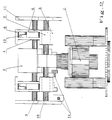
- the axis of the worm wheel, which is extended on both sides, is designed as a spindle 3.
- a spindle nut 4 runs on each spindle side, which is firmly connected to the guide and drive area 5 of a support, the direction of movement of the two supports being in opposite directions.
- Each guide and drive area 5 of the support has two bores with sliding bushes 9, which are located on both sides of the spindle nut 4.
- each support moves for guidance on two guide bolts 10, which are each firmly connected to the gear housing 2 and a housing side wall 11 of the stable housing 12.
- the housing also has a support function.
- Each guide and drive area 5 of the support is laterally firmly connected via four webs 6 with a finger mounting plate 8 for the respective gripper finger, two parallel webs 6, which are located one behind the other in the direction of movement, in the vicinity of a sliding bush 9 with the guide and drive area 5 of the Supports are connected.
Abstract
Bei einem Parallelgreifer mit Spindelantrieb, bei dem für die beiden Greiffinger oder für jeden Finger separat die Schnecke eines Schneckenradgetriebes mit einem Elektromotor (1), vorzugsweise Schrittmotor, verbunden ist und die verlängerte Achse des Schneckenrades als Spindel (3) ausgeführt ist, auf der sich ein oder zwei in Bewegungsrichtung der Finger geführte und damit gegen die Verdrehung gesicherte Supporte mit jeweils einer Spindeldürre bewegen, wobei bei zwei vorgesehenen Supporten diese sich beidseitig des Schneckenrads auf der Spindel gegenläufig bewegen, mit einer Kraftmeßeinrichtung für jeden Finger unter Verwendung von Verformabschnitten mit Dehnungsindikatoren (7), ist vorgesehen, daß der Führungs- und Antriebsbereich des Supports über vier Stege (6) zur Messung der am jeweiligen Greiffinger angreifenden Greifkraft übe die Verbiegung der Stege nur in Bewegungsrichtung der Greiffinger mit der Fingerbewegungsplatte des Supports seitlich fest verbunden ist, wobei jeweils zwei Stege parallel verlaufen und in Bewegungsrichtung der Greiffinger hintereinanderliegend angeordnet sind. <IMAGE>In the case of a parallel gripper with a spindle drive, in which the worm of a worm wheel gear is separately connected to an electric motor (1), preferably a stepper motor, for the two gripper fingers or for each finger, and the elongated axis of the worm wheel is designed as a spindle (3) on which move one or two supports guided in the direction of movement of the fingers and thus secured against rotation, each with a spindle drought, whereby with two provided supports they move in opposite directions on both sides of the worm wheel on the spindle, with a force measuring device for each finger using deformation sections with strain indicators ( 7), it is provided that the guide and drive area of the support is firmly connected laterally via four webs (6) for measuring the gripping force acting on the respective gripping finger by bending the webs only in the direction of movement of the gripping fingers with the finger movement plate of the support i Two webs each run parallel and are arranged one behind the other in the direction of movement of the gripper fingers. <IMAGE>
Description
Die Erfindung betriffl einen Parallelgreifer mit einem oder zwei Spindelantrieben nach dem Oberbegriff des Anspruchs 1.The invention relates to a parallel gripper with one or two spindle drives according to the preamble of
Bekannt ist eine Greifeinrichtung mit Greifbacken, die zur Verstellung der Greiföffnung durch einen Motor über ein Schneckengetriebe mittels Gewindespindeln verschoben werden (DE-OS 3606874).
Der Motor - insbesondere ein Schrittmotor - ist hierbei in Schneckenlängsrichtung gegen eine Vorspannkraft verschiebbar gelagert. Eine genaue Greifkraftmessung an jedem Finger sowie eine Ermittlung der Greifposition ist nicht möglich.
Weiterhin ist ein Parallelgreifer mit Spindelantrieb und Anwesenheitskontrolle bekannt (DE-OS 3905 656), bei dem durch eine spezielle Schalteranordnung in Verbindung mit der Spindelmutter während des Greifvorganges ein Schaltsignal ausgelöst wird, wenn durch einen anwesenden Körper und den dadurch auftretenden Druck auf die Finger der Schalter betätigt wird. Dieser Schalter ist mit der Motorsteuerung verbunden, die aufgabengemäß entsprechende Steuersignale für den Motor erzeugt. Auch in diesem Fall ist eine Messung und Regelung der Greifkraft nicht möglich.
Es gehören auch Lösungen zum Stand der Technik, bei denen über den aufgenommenen Motorstrom die Greifkraft indirekt ermittelt wird (DE-OS 3910801). Diese Methode ist erstens ungenau, und zweitens erlaubt sie nicht die Greifkraftermittlung am einzelnen Finger.
In der US-PS 4132 318 wird ein Manipulatorsystem mit einem Zweifingergreifer beschrieben, bei welchem jeder Finger über ein sechskomponentiges Kraft-Momentensystem mit dem Greiffingerantrieb verbunden ist. Beide Meßsysteme sind asymmetrisch. Kräfte und Momente werden über gemessene Verformungen ermittelt.
Diese Greifanordnung ist nicht stabil, ein zuverlässiges, determiniertes Greifen kann nicht erfolgen, da die Finger in allen Richtungen auslenkbar sind.
Darüber hinaus sind Überlastsicherungen nicht ersichtlich und möglich.Known is a gripping device with gripping jaws which are displaced by a motor to adjust the gripping opening via a worm gear by means of threaded spindles (DE-OS 3606874).
The motor - in particular a stepper motor - is mounted displaceably in the longitudinal direction of the screw against a pretensioning force. An exact gripping force measurement on each finger and a determination of the gripping position is not possible.
Furthermore, a parallel gripper with a spindle drive and presence control is known (DE-OS 3905 656), in which a switching signal is triggered by a special switch arrangement in connection with the spindle nut during the gripping process if the body is present and the pressure on the fingers caused by this occurs Switch is operated. This switch is connected to the engine control, which generates corresponding control signals for the engine according to the task. In this case, too, it is not possible to measure and regulate the gripping force.
Solutions also belong to the prior art, in which the gripping force is determined indirectly via the motor current consumed (DE-OS 3910801). First, this method is imprecise, and second, it does not allow gripping force to be determined on a single finger.
US Pat. No. 4,132,318 describes a manipulator system with a two-finger gripper, in which each finger is connected to the gripper finger drive via a six-component force-moment system. Both measuring systems are asymmetrical. Forces and moments are determined via measured deformations.
This gripping arrangement is not stable, reliable, determined gripping cannot take place since the fingers can be deflected in all directions.
In addition, overload protection devices are not visible and possible.
Der in Anspruch 1 angegebenen Erfindung liegt das Problem zugrunde, das direkte Messen der Greifkraft an den einzelnen Fingern von Parallelgreifern sicher und zuverlässig bei möglichst geringem gerätetechnischen Aufwand zu gewährleisten.The invention specified in
Die mit der Erfindung erzielten Vorteile bestehen insbesondere darin, daß durch die erfindungsgemäße Ausgestaltung der Supporte eine direkte und genaue Messung der Greifkraft an jedem Finger determiniert erfolgt, wobei nur in Richtung der Greiffingerbewegung Verformungen der Meßstege auftreten und ein Abkippen der Finger nicht möglich ist.
Über eine Steuereinrichtung gemäß Anspruch 2, die Signale der Dehnungsindikatoren erhält, und den mit ihr verbundenen Motor ist es somit möglich, die Greifkraft zu programmieren, den Greifabstand, d.h. die Größe des gegriffenen Körpers zu ermitteln und auch die Positon des Körpers zum Greifen von fixierten Teilen festzustellen.The advantages achieved by the invention are, in particular, that the support according to the invention provides a direct and precise measurement of the gripping force on each finger, with deformations of the measuring webs occurring only in the direction of the gripping finger movement and the fingers not being able to tip over.
Via a control device according to
Ein Ausführungsbeispiel der Erfindung ist in der Zeichnung dargestellt und wird im folgenden näher beschrieben.
Dabei zeigen
- Fig. 1 eine perspektivische Ansicht des Greifers ohne Gehäuse
- Fig. 2 eine Schnittdarstellung des Greifers
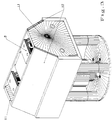
- Fig. 3 eine perspektivische Ansicht des Greifers mit Gehäuse.
Show
- Fig. 1 is a perspective view of the gripper without a housing
- Fig. 2 is a sectional view of the gripper
- Fig. 3 is a perspective view of the gripper with the housing.
Ein als Schrittmotor ausgeführter Elektromotor 1, dessen Befestigung an einer Grundplatte und Verbindung mit einem Getriebegehäuse 2 eines Schneckenradgetriebes auf bekannte Art und Weise erfolgt und deshalb nicht näher erläutert wird, treibt das an sich bekannte und deshalb ebenfalls nicht näher dargestellte Schneckenradgetriebe an. Die beidseitig verlängerte Achse des Schneckenrades ist als Spindel 3 ausgeführt. Auf jeder Spindelseite läuft eine Spindelmutter 4, die mit dem Führungs- und Antriebsbereich 5 eines Supports fest verbunden ist, wobei die Bewegungsrichtung der beiden Supporte gegenläufig ist.
Jeder Führungs- und Antriebsbereich 5 des Supports weist zwei Bohrungen mit Gleitbuchsen 9 auf, die sich beidseitig der Spindelmutter 4 befinden.
Mit diesen Gleitbuchsen 9 bewegt sich jeder Support zur Führung auf zwei Führungsbolzen 10, die jeweils mit dem Getriebegehäuse 2 und einer Gehäuseseitenwand 11 des stabilen Gehäuses 12 fest verbunden sind.
Das Gehäuse hat neben der Schutz- und Abschlußfunktion auch eine Stützfunktion.
Jeder Führungs- und Antriebsbereich 5 des Supports ist über vier Stege 6 mit einer Fingerbefestigungsplatte 8 für den jeweiligen Greiffinger seitlich fest verbunden, wobei jeweils zwei parallel verlaufende, in Bewegungsrichtung hintereinanderliegende Stege 6 in der Nähe einer Gleitbuchse 9 mit dem Führungs- und Antriebsbereich 5 des Supports verbunden sind.An
Each guide and
With these
In addition to the protection and termination function, the housing also has a support function.
Each guide and
An jedem Steg 6 befindet sich ein Dehnungsindikator 7 - Dehnmeßstreifen.
Die Abmessungen der Stege sind in Richtung der Greifbewegung geringer ausgeführt als in der dazu senkrechten Richtung, so daß mit der erfindungsgemäßen Lösung nur in der Greifrichtung eine gezielte Verbiegung auftritt. Die zwei jeweils in Greifbewegungsrichtung hintereinander angeordneten Stege bewirken, daß bei Belastung die Fingerbefestigungsplatte 8 nicht abkippt, sondern annähernd parallel verschoben wird.
Zur Verhinderung einer Überbeanspruchung der Stege 6 mit den Dehnungsindikatoren 7 ist ein Überlastschutz 13 vorgesehen. Dieser besteht aus einstellbaren Anschlägen, die jeweils an der Fingerbefestigungsplatte 8 und dem Führungs- und Antriebsbereich 5 des Supports befestigt sind.
Weiterhin sind induktive Geber 14 als Endlagenschalter zur Rückmeldung über den Öffnungszustand des Greifers vorhanden.
Sie dienen gleichzeitig zur zusätzlichen Überlastsicherung und Synchronisation.
Während des Greifens eines Körpers werden auf Grund der auf die Finger ausgeübten Kraft die Stege verbogen. Dadurch werden über die Dehnmeßstreifen Meßsignale über die am jeweiligen Finger angreifenden Kräfte erzeugt, die einer Steuereinheit zugeführt werden.
Diese erhält auch Signale von einer an sich bekannten Motordrehzahl- und -drehwinkelmeßeinrichtung, die bei Verwendung eines Schrittmotors die ausgeführten Schritte ermittelt und zählt.
Mit aufgabengemäßer und einem Fachmann geläufiger Auswertung dieser Signale mittels der Steuereinheit kann also die
- Schrittweite programmiert werden,
- der Greifabstand bestimmt werden, z.B. zum Teile sortieren,
- die Greifkraft programmiert werden, z.B. für eine Montage mit minimalen Fügekräften,
- die Position des Körpers zum Greifen von fixierten Teilen ermittelt werden.
Ist jedem Finger ein separater Antrieb zugeordnet, so kann die Greifbewegung auch asymmetrisch erfolgen, so daß auch nicht exakt geordnete Teile gegriffen werden können, ohne den Greifer extra zu bewegen.There is a strain indicator 7 - strain gauge on each web 6.
The dimensions of the webs are made smaller in the direction of the gripping movement than in the direction perpendicular thereto, so that with the solution according to the invention a targeted bending only occurs in the gripping direction. The two webs arranged one behind the other in the gripping movement direction ensure that the
An
Furthermore,
They also serve as additional overload protection and synchronization.
During the gripping of a body, the bars are bent due to the force exerted on the fingers. As a result, measurement signals are generated via the strain gauges about the forces acting on the respective fingers, which are fed to a control unit.
This also receives signals from a motor speed and rotation angle measuring device known per se, which, when using a stepping motor, determines and counts the steps carried out.
With the evaluation of these signals by means of the control unit according to the task and familiar to a person skilled in the art, the
- Step size can be programmed,
- the gripping distance can be determined, e.g. for sorting parts,
- the gripping force can be programmed, e.g. for assembly with minimal joining forces,
- the position of the body for gripping fixed parts can be determined.
If a separate drive is assigned to each finger, the gripping movement can also take place asymmetrically, so that parts that are not exactly ordered can be gripped without having to move the gripper separately.
- 11
- ElektromotorElectric motor
- 22nd
- GetriebegehäuseGear housing
- 33rd
- Spindelspindle
- 44th
- SpindelmutterSpindle nut
- 55
- Führungs- und Antriebsbereich des SupportsManagement and drive area of the support
- 66
- StegeWalkways
- 77
- DehnungsindikatorElongation indicator
- 88th
- Fingerbefestigungsplatte des SupportsSupport's finger mounting plate
- 99
- GleitbuchseSliding bush
- 1010th
- FührungsbolzenGuide pin
- 1111
- GehäuseseitenwandHousing side wall
- 1212th
- Gehäusecasing
- 1313
- ÜberlastschutzOverload protection
- 1414
- induktive Geberinductive encoder
Claims (2)
bei dem für die beiden Greiffinger oder für jeden Finger separat die Schnecke eines Schneckenradgetriebes mit einem Elektromotor, vorzugsweise Schrittmotor, verbunden ist und die verlängerte Achse des Schneckenrades als Spindel ausgeführt ist, auf der sich ein oder zwei in Bewegungsrichtung der Finger geführte und damit gegen Verdrehung gesicherte Supporte mit jeweils einer Spindelmutter bewegen, wobei bei zwei vorgesehenen Supporten diese sich beidseitig des Schneckenrades auf der Spindel gegenläufig bewegen, mit einer Kraftmeßeinrichtung für jeden Finger unter Verwendung von Verformabschnitten mit Dehnungsindikatoren,
dadurch gekennzeichnet,
daß der Führungs- und Antriebsbereich (5) des Supports über vier Stege (6) zur Messung der am jeweiligen Greiffinger angreifenden Greifkraft über die Verbiegung der Stege nur in Bewegungsrichtung der Greiffinger mit der Fingerbefestigungsplatte (8) des Supports seitlich fest verbunden ist, wobei jeweils zwei Stege (6) parallel verlaufen und in Bewegungsrichtung der Greiffinger hintereinanderliegend angeordnet sind.Parallel gripper with spindle drive,
in which for the two gripping fingers or for each finger, the worm of a worm gear is connected to an electric motor, preferably a stepping motor, and the elongated axis of the worm wheel is designed as a spindle on which one or two are guided in the direction of movement of the fingers and thus against rotation move secured supports with one spindle nut each, whereby with two provided supports these move in opposite directions on both sides of the worm wheel on the spindle, with a force measuring device for each finger using deformation sections with strain indicators,
characterized,
that the guide and drive area (5) of the support via four webs (6) for measuring the gripping force acting on the respective gripping finger via the bending of the webs only in the direction of movement of the gripping finger with the finger mounting plate (8) of the support is firmly connected laterally, in each case two webs (6) run parallel and are arranged one behind the other in the direction of movement of the gripping fingers.
daß die Dehnungsindikatoren (7) an eine Steuereinrichtung angeschlossen sind, die nach aufgabengemäßer Auswertung der Signale der Dehnungsindikatoren sowie der Signale einer ebenfalls angeschlossenen Motordrehzahl- und -drehwinkelmeßeinrichtung, z.B. nach Erreichen einer bestimmten Kraft, entsprechende Steuersignale an den ebenfalls angeschlossenen Elektromotor abgibt.Parallel gripper according to claim 1, characterized in that
that the strain indicators (7) are connected to a control device which, after evaluating the task of the signals of the strain indicators and the signals of a motor speed and rotation angle measuring device which is also connected, for example after reaching a certain force, emits corresponding control signals to the likewise connected electric motor.
Applications Claiming Priority (2)
| Application Number | Priority Date | Filing Date | Title |
|---|---|---|---|
| DE4411319 | 1994-03-28 | ||
| DE4411319A DE4411319C1 (en) | 1994-03-28 | 1994-03-28 | Parallel gripper with spindle drive |
Publications (2)
| Publication Number | Publication Date |
|---|---|
| EP0679480A1 true EP0679480A1 (en) | 1995-11-02 |
| EP0679480B1 EP0679480B1 (en) | 1998-09-02 |
Family
ID=6514402
Family Applications (1)
| Application Number | Title | Priority Date | Filing Date |
|---|---|---|---|
| EP95104534A Expired - Lifetime EP0679480B1 (en) | 1994-03-28 | 1995-03-28 | Parallel gripper with drive screw |
Country Status (4)
| Country | Link |
|---|---|
| US (1) | US5609381A (en) |
| EP (1) | EP0679480B1 (en) |
| JP (1) | JP2875182B2 (en) |
| DE (2) | DE4411319C1 (en) |
Cited By (3)
| Publication number | Priority date | Publication date | Assignee | Title |
|---|---|---|---|---|
| CN102275159A (en) * | 2010-06-14 | 2011-12-14 | 株式会社丰电子工业 | Mechanical hand device and robot with multiple joints |
| US9321229B2 (en) | 2011-07-13 | 2016-04-26 | Krones Ag | One-star system for feeding and discharging containers for processing machines |
| US9463591B2 (en) | 2011-04-13 | 2016-10-11 | Krones Ag | Container treatment machine and method of treating containers |
Families Citing this family (12)
| Publication number | Priority date | Publication date | Assignee | Title |
|---|---|---|---|---|
| DE19817426B4 (en) * | 1998-04-18 | 2004-06-09 | J. Schmalz Gmbh | Gripper system, in particular vacuum gripper system |
| KR100860522B1 (en) * | 2002-03-23 | 2008-09-26 | 엘지디스플레이 주식회사 | Conveying apparatus of liquid crystal display panel |
| WO2003105702A2 (en) * | 2002-06-14 | 2003-12-24 | Power Medical Interventions, Inc. | Surgical device |
| DE10247731B4 (en) * | 2002-10-12 | 2007-04-12 | Eppendorf Ag | Gripping tool, dosing tool and tool holder for a laboratory automat |
| US7490881B2 (en) * | 2004-09-20 | 2009-02-17 | Phd, Inc. | Long travel gripper |
| US7670555B2 (en) * | 2006-09-08 | 2010-03-02 | Rex A. Hoover | Parallel gripper for handling multiwell plate |
| EP2197363B1 (en) | 2007-09-21 | 2016-11-02 | Covidien LP | Surgical device |
| WO2009039510A1 (en) | 2007-09-21 | 2009-03-26 | Power Medical Interventions, Inc. | Surgical device |
| US10096461B2 (en) | 2011-06-23 | 2018-10-09 | Brooks Automation Germany, GmbH | Semiconductor cleaner systems and methods |
| DE102011108148A1 (en) | 2011-07-20 | 2013-01-24 | M. Mohsen Saadat | Modular gripping mechanism for heavy loads |
| JP5543539B2 (en) * | 2012-07-25 | 2014-07-09 | ファナック株式会社 | Force control electric hand |
| JP7000838B2 (en) * | 2017-12-18 | 2022-01-19 | セイコーエプソン株式会社 | Grip hand and robot |
Citations (5)
| Publication number | Priority date | Publication date | Assignee | Title |
|---|---|---|---|---|
| US4478089A (en) * | 1982-06-29 | 1984-10-23 | International Business Machines Corporation | Tri-axial force transducer for a manipulator gripper |
| EP0147082A2 (en) * | 1983-11-30 | 1985-07-03 | Fujitsu Limited | Force controlling system |
| GB2184996A (en) * | 1986-01-04 | 1987-07-08 | Gen Electric Co Plc | Robot finger |
| US4819978A (en) * | 1986-06-27 | 1989-04-11 | California Institute Of Technology | Grasp force sensor for robotic hands |
| DE3822435A1 (en) * | 1988-07-02 | 1990-01-04 | Fraunhofer Ges Forschung | Assembly device for precise positioning and mounting of parts with vibration support |
Family Cites Families (10)
| Publication number | Priority date | Publication date | Assignee | Title |
|---|---|---|---|---|
| US4132318A (en) * | 1976-12-30 | 1979-01-02 | International Business Machines Corporation | Asymmetric six-degree-of-freedom force-transducer system for a computer-controlled manipulator system |
| US4456293A (en) * | 1982-08-24 | 1984-06-26 | International Business Machines Corporation | Article gripping apparatus |
| DD218305B1 (en) * | 1983-05-05 | 1987-06-24 | Wismar Ing Hochschule | APPARATUS FOR HANDLING WORKSPIECES |
| FR2551389B1 (en) * | 1983-09-02 | 1987-02-06 | Calhene | MULTIPLE CONTACT PAD GRIPPER |
| US4579380A (en) * | 1983-12-06 | 1986-04-01 | Carnegie-Mellon University | Servo robot gripper |
| DD245616A1 (en) * | 1984-08-17 | 1987-05-13 | Ilmenau Tech Hochschule | POWERFUL TWO-TONE GRIPPERS FOR INDUSTRIAL ROBOTS |
| DE3606874A1 (en) * | 1986-03-03 | 1987-09-17 | Fraunhofer Ges Forschung | Gripping device with gripper jaws |
| US4699414A (en) * | 1986-04-21 | 1987-10-13 | The United States Of America As Represented By The Secretary Of The Air Force | Multi use gripper for industrial robot |
| DD271077A1 (en) * | 1988-03-28 | 1989-08-23 | Adw Ddr Kybernetik Inf | PARALLEL GRIPPERS WITH SPINDLE DRIVE AND PRESENCE CONTROL |
| DE3910801A1 (en) * | 1989-04-04 | 1990-10-18 | Schunk Fritz Gmbh | Gripping device |
-
1994
- 1994-03-28 DE DE4411319A patent/DE4411319C1/en not_active Expired - Fee Related
-
1995
- 1995-03-27 JP JP7068435A patent/JP2875182B2/en not_active Expired - Fee Related
- 1995-03-28 DE DE59503403T patent/DE59503403D1/en not_active Expired - Fee Related
- 1995-03-28 US US08/413,856 patent/US5609381A/en not_active Expired - Fee Related
- 1995-03-28 EP EP95104534A patent/EP0679480B1/en not_active Expired - Lifetime
Patent Citations (5)
| Publication number | Priority date | Publication date | Assignee | Title |
|---|---|---|---|---|
| US4478089A (en) * | 1982-06-29 | 1984-10-23 | International Business Machines Corporation | Tri-axial force transducer for a manipulator gripper |
| EP0147082A2 (en) * | 1983-11-30 | 1985-07-03 | Fujitsu Limited | Force controlling system |
| GB2184996A (en) * | 1986-01-04 | 1987-07-08 | Gen Electric Co Plc | Robot finger |
| US4819978A (en) * | 1986-06-27 | 1989-04-11 | California Institute Of Technology | Grasp force sensor for robotic hands |
| DE3822435A1 (en) * | 1988-07-02 | 1990-01-04 | Fraunhofer Ges Forschung | Assembly device for precise positioning and mounting of parts with vibration support |
Non-Patent Citations (1)
| Title |
|---|
| GLASSMAN: "COMPLIANT GRIPPER", IBM TECHNICAL DISCLOSURE BULLETIN, vol. 27, no. 1B, NEW YORK US, pages 772 - 773 * |
Cited By (3)
| Publication number | Priority date | Publication date | Assignee | Title |
|---|---|---|---|---|
| CN102275159A (en) * | 2010-06-14 | 2011-12-14 | 株式会社丰电子工业 | Mechanical hand device and robot with multiple joints |
| US9463591B2 (en) | 2011-04-13 | 2016-10-11 | Krones Ag | Container treatment machine and method of treating containers |
| US9321229B2 (en) | 2011-07-13 | 2016-04-26 | Krones Ag | One-star system for feeding and discharging containers for processing machines |
Also Published As
| Publication number | Publication date |
|---|---|
| JP2875182B2 (en) | 1999-03-24 |
| JPH07299789A (en) | 1995-11-14 |
| DE4411319C1 (en) | 1995-06-01 |
| EP0679480B1 (en) | 1998-09-02 |
| DE59503403D1 (en) | 1998-10-08 |
| US5609381A (en) | 1997-03-11 |
Similar Documents
| Publication | Publication Date | Title |
|---|---|---|
| EP0679480B1 (en) | Parallel gripper with drive screw | |
| DE2628701C2 (en) | ||
| DE102016011698B4 (en) | Robot operating device with handles for operating a robot | |
| AT391459B (en) | DEVICE FOR HANDLING COMPONENTS WITH A GRIP DEVICE | |
| DE3622924C2 (en) | Device for folding sheet metal | |
| EP1291616A2 (en) | Device for detecting relative motion of two objects | |
| DE2928153C2 (en) | Brake testing device | |
| EP1448954A1 (en) | Arrangement for detecting relative movements or relative positions of two objects | |
| DE3417991A1 (en) | PROBE HEAD OF A MEASURING MACHINE | |
| EP3483576B1 (en) | Device for measuring loads, preferably traction, pressure and/or torsion loads acting on a commercial vehicle running gear part | |
| EP0703393B1 (en) | Valve lift checking device | |
| DE102018216692B3 (en) | Robot hand guiding device | |
| EP2114600B1 (en) | Counterbalanced boring tool | |
| EP0177922A1 (en) | Safety device for an industrial robot | |
| DE3606874C2 (en) | ||
| EP0822387B1 (en) | Coordinates measuring apparatus with collision protection | |
| EP1425513B1 (en) | Sensor device and method for arranging a sensor device on a mounting plate | |
| CH658311A5 (en) | MEASURING DEVICE FOR DETERMINING LENGTH DIMENSIONS. | |
| DE102018220482A1 (en) | Collision detector for a robot arm | |
| DE102018205337B4 (en) | gripper | |
| DE202005001659U1 (en) | Welding tongs with two hinged arms with electrodes at their free ends and deformation sensors, useful for welding sheets in automobile production | |
| DE19944457C1 (en) | Precision robot with parallel kinematics | |
| DE3606685A1 (en) | DEVICE FOR HANDLING AN INDUSTRIAL ROBOT | |
| DD260029B1 (en) | COLLISION SENSOR | |
| DE10138684C2 (en) | Gripping or tensioning device |
Legal Events
| Date | Code | Title | Description |
|---|---|---|---|
| PUAI | Public reference made under article 153(3) epc to a published international application that has entered the european phase |
Free format text: ORIGINAL CODE: 0009012 |
|
| AK | Designated contracting states |
Kind code of ref document: A1 Designated state(s): DE GB IT NL |
|
| RIN1 | Information on inventor provided before grant (corrected) |
Inventor name: ZIER, PETER Inventor name: JOHANSEN, WOLFGANG Inventor name: NEUMANN, ALFRED Inventor name: THOM, HEINZ, DR.-ING. |
|
| 17P | Request for examination filed |
Effective date: 19960427 |
|
| 17Q | First examination report despatched |
Effective date: 19970611 |
|
| RAP1 | Party data changed (applicant data changed or rights of an application transferred) |
Owner name: SIEMENS AKTIENGESELLSCHAFT |
|
| GRAG | Despatch of communication of intention to grant |
Free format text: ORIGINAL CODE: EPIDOS AGRA |
|
| GRAG | Despatch of communication of intention to grant |
Free format text: ORIGINAL CODE: EPIDOS AGRA |
|
| GRAH | Despatch of communication of intention to grant a patent |
Free format text: ORIGINAL CODE: EPIDOS IGRA |
|
| GRAH | Despatch of communication of intention to grant a patent |
Free format text: ORIGINAL CODE: EPIDOS IGRA |
|
| GRAA | (expected) grant |
Free format text: ORIGINAL CODE: 0009210 |
|
| AK | Designated contracting states |
Kind code of ref document: B1 Designated state(s): DE GB IT NL |
|
| REF | Corresponds to: |
Ref document number: 59503403 Country of ref document: DE Date of ref document: 19981008 |
|
| GBT | Gb: translation of ep patent filed (gb section 77(6)(a)/1977) |
Effective date: 19981106 |
|
| PG25 | Lapsed in a contracting state [announced via postgrant information from national office to epo] |
Ref country code: GB Free format text: LAPSE BECAUSE OF NON-PAYMENT OF DUE FEES Effective date: 19990328 |
|
| PLBE | No opposition filed within time limit |
Free format text: ORIGINAL CODE: 0009261 |
|
| STAA | Information on the status of an ep patent application or granted ep patent |
Free format text: STATUS: NO OPPOSITION FILED WITHIN TIME LIMIT |
|
| 26N | No opposition filed | ||
| PG25 | Lapsed in a contracting state [announced via postgrant information from national office to epo] |
Ref country code: NL Free format text: LAPSE BECAUSE OF NON-PAYMENT OF DUE FEES Effective date: 19991001 |
|
| GBPC | Gb: european patent ceased through non-payment of renewal fee |
Effective date: 19990328 |
|
| NLV4 | Nl: lapsed or anulled due to non-payment of the annual fee |
Effective date: 19991001 |
|
| PGFP | Annual fee paid to national office [announced via postgrant information from national office to epo] |
Ref country code: DE Payment date: 20070521 Year of fee payment: 13 |
|
| PGFP | Annual fee paid to national office [announced via postgrant information from national office to epo] |
Ref country code: IT Payment date: 20070524 Year of fee payment: 13 |
|
| PG25 | Lapsed in a contracting state [announced via postgrant information from national office to epo] |
Ref country code: DE Free format text: LAPSE BECAUSE OF NON-PAYMENT OF DUE FEES Effective date: 20081001 |
|
| PG25 | Lapsed in a contracting state [announced via postgrant information from national office to epo] |
Ref country code: IT Free format text: LAPSE BECAUSE OF NON-PAYMENT OF DUE FEES Effective date: 20080328 |