EP0677754A1 - Method and apparatus for well logging using an accelerator neutron source - Google Patents
Method and apparatus for well logging using an accelerator neutron source Download PDFInfo
- Publication number
- EP0677754A1 EP0677754A1 EP95302295A EP95302295A EP0677754A1 EP 0677754 A1 EP0677754 A1 EP 0677754A1 EP 95302295 A EP95302295 A EP 95302295A EP 95302295 A EP95302295 A EP 95302295A EP 0677754 A1 EP0677754 A1 EP 0677754A1
- Authority
- EP
- European Patent Office
- Prior art keywords
- neutrons
- neutron
- detector
- source
- neutron source
- Prior art date
- Legal status (The legal status is an assumption and is not a legal conclusion. Google has not performed a legal analysis and makes no representation as to the accuracy of the status listed.)
- Granted
Links
- 238000000034 method Methods 0.000 title claims abstract description 31
- 230000015572 biosynthetic process Effects 0.000 claims abstract description 67
- 239000011159 matrix material Substances 0.000 claims abstract description 18
- 230000001678 irradiating effect Effects 0.000 claims abstract description 8
- WFKWXMTUELFFGS-UHFFFAOYSA-N tungsten Chemical compound [W] WFKWXMTUELFFGS-UHFFFAOYSA-N 0.000 claims description 9
- 229910052721 tungsten Inorganic materials 0.000 claims description 9
- 239000010937 tungsten Substances 0.000 claims description 9
- 239000000463 material Substances 0.000 claims description 7
- 238000005553 drilling Methods 0.000 claims description 2
- 238000006243 chemical reaction Methods 0.000 description 15
- 230000005251 gamma ray Effects 0.000 description 10
- 230000004907 flux Effects 0.000 description 8
- 230000004044 response Effects 0.000 description 8
- UFHFLCQGNIYNRP-UHFFFAOYSA-N Hydrogen Chemical compound [H][H] UFHFLCQGNIYNRP-UHFFFAOYSA-N 0.000 description 7
- 229910052739 hydrogen Inorganic materials 0.000 description 7
- 239000001257 hydrogen Substances 0.000 description 7
- 238000005259 measurement Methods 0.000 description 7
- 239000007789 gas Substances 0.000 description 6
- 230000000694 effects Effects 0.000 description 5
- 230000003993 interaction Effects 0.000 description 5
- 238000012544 monitoring process Methods 0.000 description 3
- 239000011148 porous material Substances 0.000 description 3
- 238000012545 processing Methods 0.000 description 3
- 239000011435 rock Substances 0.000 description 3
- 239000000126 substance Substances 0.000 description 3
- 238000009792 diffusion process Methods 0.000 description 2
- 239000012530 fluid Substances 0.000 description 2
- 230000035945 sensitivity Effects 0.000 description 2
- 230000006641 stabilisation Effects 0.000 description 2
- 238000011105 stabilization Methods 0.000 description 2
- 229910052722 tritium Inorganic materials 0.000 description 2
- YBJHBAHKTGYVGT-ZKWXMUAHSA-N (+)-Biotin Chemical compound N1C(=O)N[C@@H]2[C@H](CCCCC(=O)O)SC[C@@H]21 YBJHBAHKTGYVGT-ZKWXMUAHSA-N 0.000 description 1
- 239000004593 Epoxy Substances 0.000 description 1
- 235000019738 Limestone Nutrition 0.000 description 1
- 229910052770 Uranium Inorganic materials 0.000 description 1
- 238000010521 absorption reaction Methods 0.000 description 1
- 238000013459 approach Methods 0.000 description 1
- 238000010420 art technique Methods 0.000 description 1
- 230000008901 benefit Effects 0.000 description 1
- 229910052797 bismuth Inorganic materials 0.000 description 1
- JCXGWMGPZLAOME-UHFFFAOYSA-N bismuth atom Chemical compound [Bi] JCXGWMGPZLAOME-UHFFFAOYSA-N 0.000 description 1
- 229910052793 cadmium Inorganic materials 0.000 description 1
- BDOSMKKIYDKNTQ-UHFFFAOYSA-N cadmium atom Chemical compound [Cd] BDOSMKKIYDKNTQ-UHFFFAOYSA-N 0.000 description 1
- 230000008859 change Effects 0.000 description 1
- 230000000295 complement effect Effects 0.000 description 1
- 238000010276 construction Methods 0.000 description 1
- 238000001739 density measurement Methods 0.000 description 1
- 230000001419 dependent effect Effects 0.000 description 1
- 238000009795 derivation Methods 0.000 description 1
- 230000001627 detrimental effect Effects 0.000 description 1
- 229910052805 deuterium Inorganic materials 0.000 description 1
- 239000010459 dolomite Substances 0.000 description 1
- 229910000514 dolomite Inorganic materials 0.000 description 1
- 230000002452 interceptive effect Effects 0.000 description 1
- 230000000155 isotopic effect Effects 0.000 description 1
- 239000006028 limestone Substances 0.000 description 1
- 229910052751 metal Inorganic materials 0.000 description 1
- 239000002184 metal Substances 0.000 description 1
- 230000001151 other effect Effects 0.000 description 1
- 230000002285 radioactive effect Effects 0.000 description 1
- 239000012857 radioactive material Substances 0.000 description 1
- 238000001228 spectrum Methods 0.000 description 1
- 229910052715 tantalum Inorganic materials 0.000 description 1
- GUVRBAGPIYLISA-UHFFFAOYSA-N tantalum atom Chemical compound [Ta] GUVRBAGPIYLISA-UHFFFAOYSA-N 0.000 description 1
- 150000003657 tungsten Chemical class 0.000 description 1
- JFALSRSLKYAFGM-UHFFFAOYSA-N uranium(0) Chemical compound [U] JFALSRSLKYAFGM-UHFFFAOYSA-N 0.000 description 1
- FEPMHVLSLDOMQC-UHFFFAOYSA-N virginiamycin-S1 Natural products CC1OC(=O)C(C=2C=CC=CC=2)NC(=O)C2CC(=O)CCN2C(=O)C(CC=2C=CC=CC=2)N(C)C(=O)C2CCCN2C(=O)C(CC)NC(=O)C1NC(=O)C1=NC=CC=C1O FEPMHVLSLDOMQC-UHFFFAOYSA-N 0.000 description 1
Images


Classifications
-
- G—PHYSICS
- G01—MEASURING; TESTING
- G01V—GEOPHYSICS; GRAVITATIONAL MEASUREMENTS; DETECTING MASSES OR OBJECTS; TAGS
- G01V5/00—Prospecting or detecting by the use of nuclear radiation, e.g. of natural or induced radioactivity
- G01V5/04—Prospecting or detecting by the use of nuclear radiation, e.g. of natural or induced radioactivity specially adapted for well-logging
- G01V5/08—Prospecting or detecting by the use of nuclear radiation, e.g. of natural or induced radioactivity specially adapted for well-logging using primary nuclear radiation sources or X-rays
- G01V5/10—Prospecting or detecting by the use of nuclear radiation, e.g. of natural or induced radioactivity specially adapted for well-logging using primary nuclear radiation sources or X-rays using neutron sources
- G01V5/107—Prospecting or detecting by the use of nuclear radiation, e.g. of natural or induced radioactivity specially adapted for well-logging using primary nuclear radiation sources or X-rays using neutron sources and detecting reflected or back-scattered neutrons
Definitions
- the present invention relates to a method and apparatus for well logging to determine a characteristic of an underground formation through which the well passes.
- the invention relates to a logging technique which uses an accelerator neutron source.
- a neutron source in a logging tool for obtaining a characteristic of a formation surrounding a borehole is well known, particularly in the derivation of formation porosity.
- Certain techniques involve the use of a chemical source such as 252Cf AmBe or PuBe to provide neutrons to irradiate the formation such that scattered neutrons returning to the borehole can be detected and the formation characteristic (porosity) inferred.
- a chemical source such as 252Cf AmBe or PuBe to provide neutrons to irradiate the formation such that scattered neutrons returning to the borehole can be detected and the formation characteristic (porosity) inferred.
- Such tools and methods are described in US 3,483,376 and US 3,566,117.
- chemical neutron sources have several disadvantages due to the problems in handling and shipping sources containing radioactive materials due to concerns over radioactive safety and other such matters.
- accelerator neutron sources are those base on the deuterium-tritium (D-T) reaction which produces 14MeV neutrons, the deuterium-deuterium (D-D) reaction which produces 2.5 MeV neutrons and the tritium-tritium (T-T) reaction which produces neutrons in the range 1-10 MeV with an average energy of about 5 MeV.
- D-T deuterium-tritium
- D-D deuterium-deuterium
- T-T tritium-tritium
- the '252 patent describes a neutron porosity logging tool in which an accelerator source is used to irradiate the underground formation and epithermal and thermal neutrons returning from the formation are detected. Scattering of neutrons in the formation at epithermal and thermal energies is due to interaction of the neutrons with hydrogen nuclei and so monitoring the neutrons at these energies is used to estimate the porosity of the formation since hydrogen is only associated with pore fluids rather than the rock matrix.
- the neutron porosity measurement is essentially a measurement of hydrogen density in the formation.
- an increase in matrix density for a formation can result in a decrease in count rate for a neutron porosity tool in much the same way that an increase in porosity would cause a decrease in count rate. Since it is not possible to determine which effect is causing the change merely by considering the neutron count, it is necessary to obtain an independent determination of the formation density.
- the formation density is obtained from a tool which makes use of Compton scattering of ⁇ rays by electrons to make formation matrix density measurements.
- the density tool requires a source of ⁇ rays, typically a 137Cs isotopic source.
- the tool described in the '252 patent uses 3He filled proportional counters to detect neutrons.
- Such counters are typically filled with 3He at pressures in the 10-15 atmospheres range although it has been proposed to use pressures as high as 20 atmospheres in proportional neutron counters (see US 3,102,198) and even up to 40 atmospheres, and are sensitive mainly to epithermal and thermal neutrons.
- 3He proportional counters suffer from certain problems.
- the signal in a 3He counter is produced by a proton which is the result of the reaction between a He nucleus and a neutron.
- signals can also be produced by the interaction of a 3He nucleus with a ⁇ ray and this interferes with the signal produced by neutron interactions.
- the normal approach to discriminating between neutron and ⁇ ray induced events is by peak height/signal strength analysis since the neutron induced events occur at different energies to ⁇ ray events.
- This problem is compounded by increasing the He pressure inside the counter which, while increasing the sensitivity of the counter to neutron events, makes the counter comparatively more sensitive to ⁇ ray induced events and so the interfering effect is greater. This problem is particularly significant in a borehole environment where the naturally occurring ⁇ ray activity is high.
- 4He has been used in proportional counters for detecting neutrons having MeV energies. However, 4He has a strong resonance at 1MeV which makes the neutron response highly energy dependent. Furthermore, 4He has a cutoff in the response below 1 MeV which makes it insensitive to epithermal neutrons. For this reason, 4He has not been considered as generally acceptable for proportional counters in neutron detectors.
- the present invention comprises a borehole neutron logging tool including neutron detectors which are sensitive to neutrons with energies higher than epithermal, typically in the MeV energy region.
- a first aspect of the present invention comprises a method of determining a characteristic of an underground formation through which a borehole passes comprising irradiating the underground formation with neutrons using a tool comprising a neutron source and a neutron detector, detecting neutrons originating from the source with the neutron detector at energies higher than epithermal so as to produce a signal, and using the signal to determine the characteristic of the underground formation.
- a second aspect of the invention comprises an apparatus for determining a characteristic of an underground formation through which a borehole passes comprising a neutron source for irradiating the underground formation with neutrons when the apparatus is positioned in the borehole and a neutron detector for detecting neutrons originating from the source having energies higher than epithermal so as to produce a signal related to the characteristic of the underground formation.
- a third aspect of the invention comprises the use of a 4He detector in a neutron logging tool.
- the invention comprises a technique for determining the nature of the underground formation matrix, comprising irradiating the formation with 14 MeV neutrons from a D-T accelerator and detecting neutrons at about 1MeV which have passed through the formation and have been slowed down by scattering with nuclei in the formation so as to determine the slowing down length for the 14-1MeV transport which can be used to give useful information about the composition of the formation and the presence of gas.
- the invention comprises a technique for monitoring the flow of neutrons directly from the accelerator source, typically a D-T accelerator producing 14 MeV neutrons, and which have not passed through the underground formation.
- the accelerator source typically a D-T accelerator producing 14 MeV neutrons
- the detector comprises a high pressure 4He proportional counter and that the 4He pressure in the counter be as high as possible, typically in the region of 40 atmospheres. Where the detector is used to detect neutrons which have been scattered by the formation, the high Z shielding is absent.
- FIG. 1 shows a schematic view of a prior art tool as described in US 4,760,252.
- the tool comprises a tool body or sonde 10 which can be lowered into a borehole and logged using a wireline cable in the conventional manner.
- the sonde 10 includes a DT accelerator neutron source 12, a source monitor 14 for monitoring the neutron output of the source 12, a near epithermal neutron detector 16, a thermal/epithermal neutron detector array 17, a far epithermal neutron detector 18 and a thermal neutron detector 20.
- the monitor 14 can typically comprise a scintillator and photo multiplier tube arrangement and the detectors 16, 17, 18 and 20 are 15 atm 3He proportional counters having appropriate shielding in the form of Cd metal and B4C epoxy.
- a tool according to the present invention will have generally the same configurations this prior art tool, but with the differences which will be described below.
- FIG. 2 shows a schematic view of a tool according one embodiment of the present invention.
- the tool comprises a sonde 30 including a D-T accelerator neutron source 32 which produces 14 MeV neutrons when activated, a near neutron detector 34 comprising a 40 atm 4He proportional counter shielded with a layer of tungsten 36 (or other high -Z material such as tantalum, uranium, lead and bismuth).
- tungsten 36 or other high -Z material such as tantalum, uranium, lead and bismuth.
- the path length of 14 MeV neutrons through the shielding material should be at least 1 mean-free-path for an (n, 2n) reaction, which for tungsten is 7.9 cm.
- a far neutron detector 38 comprises a further 40 atm 4He proportional counter.
- the counters 34 and 38 are located 5''-9'' and 20''-75'' from the source 32, respectively.
- the near detector can comprise some form of source monitor other than a 4He counter such as a scintillator in which case the high-Z shielding might not be required.
- Another alternative comprises 3He proportional counters as well as 4He proportional counters as the near and/or far detectors in order to measure epithermal and thermal neutrons as well as those of MeV energies.
- An intermediate detector array 37 can also be present.
- the 40 atm 4He proportional counters 34, 38 are of similar size and shape to the conventional 15 atm 3He counters and the output signal is in a generally similar form. Certain aspects of the counter construction may need to be different to withstand the higher pressure inside the counter. 40 atm 4He proportional counter of the type described can be obtained from GE Reuter Stokes Inc. of Twinsburg, Ohio, USA.
- the 4He scattering cross section for neutrons in the 0-14 MeV energy range is shown in Figure 3.
- the scattering spectrum does not have any strong peaks which can be used for gain stabilization so an internal ⁇ -source, such as 234U may be added.
- gain stabilization requires a pulsed accelerator so that the a-source counts can be accumulated during source-off periods.
- the 1 MeV resonance might normally be considered detrimental to the performance of a neutron detector.
- this feature can be put to use when using a 14 MeV neutron source both when attempting to obtain the characteristics of the formation matrix and when attempting to discriminate against epithermal neutrons.
- the neutrons interact with tungsten nuclei in the shielding to produce two product neutrons (another possible reaction produces three product neutrons).
- This reaction has a negative Q value equal to the binding energy of a neutron, approximately -6.5 MeV. The remaining 7.5 MeV is shared among the product neutrons.
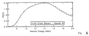
- the cross section for this reaction is shown in Figure 4 and given the high nuclear density in metallic tungsten, the interaction probability is large (mean free path for an (n,2n) reaction is 7.9 cm).
- the effect of the shielding not only increases the number of neutrons entering the counter due to the (n, 2n) reaction, but also brings these neutrons into the highly sensitive range of the counter around 1 MeV.
- the high threshold for the reaction discriminates against neutrons which have scattered many times, such as in the formation, with a corresponding loss in energy and the low energy cut off in the detector response described above means that the detector is less sensitive to neutrons which a have not traveled directly from the source.
- a conventional 3He source monitor about 50% of the detected neutrons have been scattered by the formation rather than emanating directly from the source whereas in the tungsten shielded high pressure 4He detector this figure is reduced to about 20%.
- the other effect of shielding the source monitor in this manner is to reduce the flow of 14 MeV neutrons along the tool to the far detector.
- hydrogenous shielding material may be placed between the source monitor and the far detector. This means that substantially all 1 MeV neutrons detected at the far detector result from interaction with the formation. If the near detector/source monitor is not a 4He counter with tungsten shielding, it may be necessary to place some high-Z and hydrogenous shielding in the sonde to reduce the neutron flux through the tool directly from the source to the far detector.
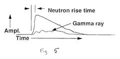
- Figure 5 shows the amplitude of the high pressure 4He detector response against time with both signals due to neutrons and ⁇ rays shown.
- the neutron induced signal is predominantly fast ( ⁇ 150 ns), low energy 4He recoil with some slower, high energy 4He recoil.
- the ⁇ ray signal is predominantly slow (up to 10 ns).
- One way to discriminate between neutron and ⁇ ray signals is to monitor only the first section of the signal, the fast signal, since this is mainly due to neutrons with little contribution from ⁇ rays.
- the portion of the signal to be measured can be determined from the variation in neutron signal with time and the time required up to the peak in the neutron signal is chosen. This is typically in the 100-150 ns range.
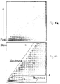
- Figure 6a comprises a cross plot of fast signals and slow signals when the source is not active, i.e. the signals are due to formation activity and thermal capture ⁇ rays only. As will be seen, most of the signal is present in a localized region ⁇ .
- Figure 6b shows the corresponding cross plot with the neutron source active.
- the 14-1 MeV transport in the formation is due to non-elastic reactions (mostly inelastic scattering, (n,p) and (n, ⁇ ) reactions) of the neutrons with nuclei such as C, O, Si, etc. contained in the rock matrix rather than hydrogen nuclei in the pore fluid which affect the transport below 1 MeV to epithermal and thermal energies.
- nuclei such as C, O, Si, etc. contained in the rock matrix rather than hydrogen nuclei in the pore fluid which affect the transport below 1 MeV to epithermal and thermal energies.
- neutrons with about 1 MeV energy have had to traverse the entire 14 - 1 MeV region where the non-elastic cross section is large and so show the greatest sensitivity to matrix effects (with some dependence also on hydrogen). Consequently, by determining the 14-1 MeV slowing down length L h , which is possible with the present invention, it is possible to obtain formation matrix information which is not available in the prior art techniques.
- Simple diffusion theory predicts a radial falloff of flux ⁇ h with distance r from the source according to: where S is the source strength and ⁇ rs is the macroscopic cross section for removal from the energy range 1 - 14 MeV. Given two measurements of the 1 MeV flux at different source/detector spacings r 1 and r 2, one can measure L h directly:
- the epithermal flux ⁇ epi follows a similar law in one group diffusion theory: where L s is the length for slowing down from 14 MeV to 0.5 eV (the cadmium cutoff). Although L has some dependence on the matrix, flux dependence on these variations vanishes at a source/detector spacing of 2 L s .
- the source factor S can be eliminated by taking a ratio with a 1 MeV flux measurement at a short source/detector spacing.
- 3He epithermal detector
- 4He 1 MeV detectors
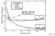
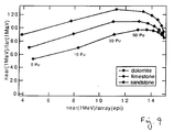
- a crossplot of these two can determine matrix and identify gas as shown in Figure 8.
- the three curves shown correspond to the three major rock matrices: dolomite (2.87 g/cc), limestone (2.71 g/cc) and sandstone (2.65 g/cc).
- dolomite (2.87 g/cc)
- limestone (2.71 g/cc)
- sandstone (2.65 g/cc).
- the near/far and near/array ratios provide almost independent measures of matrix type and porosity, respectively.
Abstract
Description
- The present invention relates to a method and apparatus for well logging to determine a characteristic of an underground formation through which the well passes. In particular the invention relates to a logging technique which uses an accelerator neutron source.
- The use of a neutron source in a logging tool for obtaining a characteristic of a formation surrounding a borehole is well known, particularly in the derivation of formation porosity. Certain techniques involve the use of a chemical source such as ²⁵²Cf AmBe or PuBe to provide neutrons to irradiate the formation such that scattered neutrons returning to the borehole can be detected and the formation characteristic (porosity) inferred. Such tools and methods are described in US 3,483,376 and US 3,566,117. However, chemical neutron sources have several disadvantages due to the problems in handling and shipping sources containing radioactive materials due to concerns over radioactive safety and other such matters. It has been proposed to use an accelerator neutron source in such logging tools which overcomes these problems since neutrons are only produced when the source is activated in use in the borehole. Examples of accelerator neutron sources are those base on the deuterium-tritium (D-T) reaction which produces 14MeV neutrons, the deuterium-deuterium (D-D) reaction which produces 2.5 MeV neutrons and the tritium-tritium (T-T) reaction which produces neutrons in the range 1-10 MeV with an average energy of about 5 MeV. An example of a D-T accelerator source is described in US 3,775,216 and an example of a well logging tool incorporating a D-T source is described in US 4,760,252. The '252 patent describes a neutron porosity logging tool in which an accelerator source is used to irradiate the underground formation and epithermal and thermal neutrons returning from the formation are detected. Scattering of neutrons in the formation at epithermal and thermal energies is due to interaction of the neutrons with hydrogen nuclei and so monitoring the neutrons at these energies is used to estimate the porosity of the formation since hydrogen is only associated with pore fluids rather than the rock matrix.
- The neutron porosity measurement is essentially a measurement of hydrogen density in the formation. However, an increase in matrix density for a formation can result in a decrease in count rate for a neutron porosity tool in much the same way that an increase in porosity would cause a decrease in count rate. Since it is not possible to determine which effect is causing the change merely by considering the neutron count, it is necessary to obtain an independent determination of the formation density. Typically, the formation density is obtained from a tool which makes use of Compton scattering of γ rays by electrons to make formation matrix density measurements. The density tool requires a source of γ rays, typically a ¹³⁷Cs isotopic source. As with neutron sources, the use of chemical γ ray sources is undesirable but there is no current accelerator-based alternative which might be used instead. Changes in matrix density and porosity have complementary effects on neutron and Compton density tools and can be determined by cross plotting neutron porosity and density. However, the inclusion of gas in the matrix pores cannot be distinguished from a decrease in matrix density since neither the neutron response nor the Compton scattering response will show anything which could be attributed solely to the presence of gas.
- The tool described in the '252 patent uses ³He filled proportional counters to detect neutrons. Such counters are typically filled with ³He at pressures in the 10-15 atmospheres range although it has been proposed to use pressures as high as 20 atmospheres in proportional neutron counters (see US 3,102,198) and even up to 40 atmospheres, and are sensitive mainly to epithermal and thermal neutrons. With these detectors it is not possible to make accurate measurements at energies above epithermal, i.e. in the MeV energy range, but since measurements in this energy region do not give information about porosity, this has not been considered a problem. ³He proportional counters suffer from certain problems. The signal in a ³He counter is produced by a proton which is the result of the reaction between a He nucleus and a neutron. However, signals can also be produced by the interaction of a ³He nucleus with a γ ray and this interferes with the signal produced by neutron interactions. The normal approach to discriminating between neutron and γ ray induced events is by peak height/signal strength analysis since the neutron induced events occur at different energies to γ ray events. This problem is compounded by increasing the He pressure inside the counter which, while increasing the sensitivity of the counter to neutron events, makes the counter comparatively more sensitive to γ ray induced events and so the interfering effect is greater. This problem is particularly significant in a borehole environment where the naturally occurring γ ray activity is high.
- ⁴He has been used in proportional counters for detecting neutrons having MeV energies. However, ⁴He has a strong resonance at 1MeV which makes the neutron response highly energy dependent. Furthermore, ⁴He has a cutoff in the response below 1 MeV which makes it insensitive to epithermal neutrons. For this reason, ⁴He has not been considered as generally acceptable for proportional counters in neutron detectors.
- It is an object of the invention to provide a neutron logging method and apparatus which can be used to obtain information of the formation matrix and identify the presence of gas in the formation.
- It is also an object of the present invention to provide a He filled proportional counter for use in a neutron detector in which the problems outlined above are obviated or mitigated.
- Broadly, the present invention comprises a borehole neutron logging tool including neutron detectors which are sensitive to neutrons with energies higher than epithermal, typically in the MeV energy region.
- A first aspect of the present invention comprises a method of determining a characteristic of an underground formation through which a borehole passes comprising irradiating the underground formation with neutrons using a tool comprising a neutron source and a neutron detector, detecting neutrons originating from the source with the neutron detector at energies higher than epithermal so as to produce a signal, and using the signal to determine the characteristic of the underground formation.
- A second aspect of the invention comprises an apparatus for determining a characteristic of an underground formation through which a borehole passes comprising a neutron source for irradiating the underground formation with neutrons when the apparatus is positioned in the borehole and a neutron detector for detecting neutrons originating from the source having energies higher than epithermal so as to produce a signal related to the characteristic of the underground formation.
- It has been found that the response of a ⁴He proportional counter is particularly suited for use in a borehole environment since it is responsive to neutrons with energies above epithermal and it is easier to discriminate between neutron and γ ray induced events such that the pressure can be increased to a higher level than would be practical in a ³He.
- A third aspect of the invention comprises the use of a ⁴He detector in a neutron logging tool.
- In one embodiment, the invention comprises a technique for determining the nature of the underground formation matrix, comprising irradiating the formation with 14 MeV neutrons from a D-T accelerator and detecting neutrons at about 1MeV which have passed through the formation and have been slowed down by scattering with nuclei in the formation so as to determine the slowing down length for the 14-1MeV transport which can be used to give useful information about the composition of the formation and the presence of gas.
- In another embodiment, the invention comprises a technique for monitoring the flow of neutrons directly from the accelerator source, typically a D-T accelerator producing 14 MeV neutrons, and which have not passed through the underground formation. In this case it is preferred to shield the high energy detector with a high Z material such as tungsten.
- It is preferred that the detector comprises a high pressure ⁴He proportional counter and that the ⁴He pressure in the counter be as high as possible, typically in the region of 40 atmospheres. Where the detector is used to detect neutrons which have been scattered by the formation, the high Z shielding is absent.
- The invention will now be described with reference to the accompanying drawings, in which:
- Figure 1 shows an embodiment of a prior art neutron logging tool;
- Figure 2 shows a schematic cross section of a tool according to one embodiment of the invention;
- Figure 3 shows the ⁴He scattering cross section for neutrons in the 0 - 14 MeV range;
- Figure 4 shows the cross section for the reaction between neutrons and the tungsten nucleus;
- Figure 5 shows the ⁴He detector response against time for neutrons and γ rays;
- Figure 6a shows a cross plot of fast and slow channel signals when the neutron source is inactive;
- Figure 6b shows a cross plot of fast and slow channel signals when the neutron source is active;
- Figure 7 shows a schematic view of the processing used for signal discrimination;
- Figure 8 shows a cross plot of slowing down length, and hydrogen index to determine matrix and identify gas; and
- Figure 9 shows a cross plot of near/far and near/array detector flux ratios.
- Referring now to the drawings, Figure 1 shows a schematic view of a prior art tool as described in US 4,760,252. The tool comprises a tool body or
sonde 10 which can be lowered into a borehole and logged using a wireline cable in the conventional manner. Thesonde 10 includes a DTaccelerator neutron source 12, asource monitor 14 for monitoring the neutron output of thesource 12, a nearepithermal neutron detector 16, a thermal/epithermalneutron detector array 17, a farepithermal neutron detector 18 and athermal neutron detector 20. Themonitor 14 can typically comprise a scintillator and photo multiplier tube arrangement and thedetectors - Figure 2 shows a schematic view of a tool according one embodiment of the present invention. The tool comprises a
sonde 30 including a D-Taccelerator neutron source 32 which produces 14 MeV neutrons when activated, a near neutron detector 34 comprising a 40 atm ⁴He proportional counter shielded with a layer of tungsten 36 (or other high -Z material such as tantalum, uranium, lead and bismuth). Preferentially, the path length of 14 MeV neutrons through the shielding material should be at least 1 mean-free-path for an
(n, 2n) reaction, which for tungsten is 7.9 cm. Afar neutron detector 38 comprises a further 40 atm ⁴He proportional counter. Thecounters 34 and 38 are located 5''-9'' and 20''-75'' from thesource 32, respectively. In an alternative embodiment, the near detector can comprise some form of source monitor other than a ⁴He counter such as a scintillator in which case the high-Z shielding might not be required. Another alternative comprises ³He proportional counters as well as ⁴He proportional counters as the near and/or far detectors in order to measure epithermal and thermal neutrons as well as those of MeV energies. Anintermediate detector array 37 can also be present. - The 40 atm ⁴He
proportional counters 34, 38 are of similar size and shape to the conventional 15 atm ³He counters and the output signal is in a generally similar form. Certain aspects of the counter construction may need to be different to withstand the higher pressure inside the counter. 40 atm ⁴He proportional counter of the type described can be obtained from GE Reuter Stokes Inc. of Twinsburg, Ohio, USA. - The ⁴He scattering cross section for neutrons in the 0-14 MeV energy range is shown in Figure 3. There is a scattering cross section resonance near 1 MeV and both scattering and absorption (not shown) cross sections are low below this energy. Consequently, the detector is relatively insensitive to epithermal and thermal neutrons. The scattering spectrum does not have any strong peaks which can be used for gain stabilization so an internal α-source, such as ²³⁴U may be added. Such gain stabilization requires a pulsed accelerator so that the a-source counts can be accumulated during source-off periods. The 1 MeV resonance might normally be considered detrimental to the performance of a neutron detector. However, it has been found that this feature can be put to use when using a 14 MeV neutron source both when attempting to obtain the characteristics of the formation matrix and when attempting to discriminate against epithermal neutrons. When the counter is being used as a source monitor, the neutrons interact with tungsten nuclei in the shielding to produce two product neutrons (another possible reaction produces three product neutrons). This reaction has a negative Q value equal to the binding energy of a neutron, approximately -6.5 MeV. The remaining 7.5 MeV is shared among the product neutrons. The cross section for this reaction is shown in Figure 4 and given the high nuclear density in metallic tungsten, the interaction probability is large (mean free path for an (n,2n) reaction is 7.9 cm). Thus the effect of the shielding not only increases the number of neutrons entering the counter due to the (n, 2n) reaction, but also brings these neutrons into the highly sensitive range of the counter around 1 MeV. The high threshold for the reaction discriminates against neutrons which have scattered many times, such as in the formation, with a corresponding loss in energy and the low energy cut off in the detector response described above means that the detector is less sensitive to neutrons which a have not traveled directly from the source. In a conventional ³He source monitor about 50% of the detected neutrons have been scattered by the formation rather than emanating directly from the source whereas in the tungsten shielded high pressure ⁴He detector this figure is reduced to about 20%.
- The other effect of shielding the source monitor in this manner is to reduce the flow of 14 MeV neutrons along the tool to the far detector. To prevent lower energy (near 1MeV) neutrons from the (n, 2n) reaction in the shielding from reaching the far detector, hydrogenous shielding material may be placed between the source monitor and the far detector. This means that substantially all 1 MeV neutrons detected at the far detector result from interaction with the formation. If the near detector/source monitor is not a ⁴He counter with tungsten shielding, it may be necessary to place some high-Z and hydrogenous shielding in the sonde to reduce the neutron flux through the tool directly from the source to the far detector.
- Figure 5 shows the amplitude of the high pressure ⁴He detector response against time with both signals due to neutrons and γ rays shown. As can be seen, the neutron induced signal is predominantly fast (∼150 ns), low energy ⁴He recoil with some slower, high energy ⁴He recoil. The γ ray signal is predominantly slow (up to 10 ns). One way to discriminate between neutron and γ ray signals is to monitor only the first section of the signal, the fast signal, since this is mainly due to neutrons with little contribution from γ rays. The portion of the signal to be measured can be determined from the variation in neutron signal with time and the time required up to the peak in the neutron signal is chosen. This is typically in the 100-150 ns range.
- In order to obtain information about the total neutron signal it is necessary to consider both fast and slow signals and so the contribution of γ rays must be removed. Figure 6a comprises a cross plot of fast signals and slow signals when the source is not active, i.e. the signals are due to formation activity and thermal capture γ rays only. As will be seen, most of the signal is present in a localized region γ. Figure 6b shows the corresponding cross plot with the neutron source active. In order to obtain the neutron signal, it is necessary to remove the signal due to γ rays. This can be done by defining cutoff A and ignoring all signals below this, defining the γ region B and removing this from the total signal, or defining a region C which includes substantially only neutron signals and deriving measurements only from this region.
- The processing scheme used to obtain the cross plots of in Figures 6a and 6b is shown in Figure 7. In its simplest form, only the fast 100 ns channel is monitored. For complete information both fast and slow (10 µs) channels must be monitored and the γ ray contribution removed as described above. Similar processing is applied to both near and far detectors.
- The 14-1 MeV transport in the formation is due to non-elastic reactions (mostly inelastic scattering, (n,p) and (n,α) reactions) of the neutrons with nuclei such as C, O, Si, etc. contained in the rock matrix rather than hydrogen nuclei in the pore fluid which affect the transport below 1 MeV to epithermal and thermal energies. Thus neutrons with about 1 MeV energy have had to traverse the entire 14 - 1 MeV region where the non-elastic cross section is large and so show the greatest sensitivity to matrix effects (with some dependence also on hydrogen). Consequently, by determining the 14-1 MeV slowing down length L h , which is possible with the present invention, it is possible to obtain formation matrix information which is not available in the prior art techniques.
- Simple diffusion theory predicts a radial falloff of flux φ h with distance r from the source according to:

where S is the source strength and Σ rs is the macroscopic cross section for removal from the energy range 1 - 14 MeV. Given two measurements of the 1 MeV flux at different source/detector spacings r₁ and r₂, one can measure L h directly:
The epithermal flux φ epi follows a similar law in one group diffusion theory:
where L s is the length for slowing down from 14 MeV to 0.5 eV (the cadmium cutoff). Although L has some dependence on the matrix, flux dependence on these variations vanishes at a source/detector spacing of 2L s . The source factor S can be eliminated by taking a ratio with a 1 MeV flux measurement at a short source/detector spacing. Thus with an epithermal detector (³He) at 2L s and two 1 MeV detectors (⁴He) at different spacings, one can measure both porosity (hydrogen index) and L h . A crossplot of these two can determine matrix and identify gas as shown in Figure 8. When considering the tool arrangement as shown in Figure 2, calling thedetectors - While the present invention has been described in relation to a wireline logging tool, it will be appreciated that it can also be used in a logging-while-drilling application with the same benefit.
Claims (37)
- A method of determining a characteristic of an underground formation through which a borehole passes using a tool comprising a high energy neutron source and a neutron detector, the method comprising irradiating the underground formation with neutrons from the neutron source, detecting neutrons originating from the source which have passed to the neutron detector via the underground formation with the neutron detector so as to produce a signal, and using the signal to determine the characteristic of the underground formation, characterized in that the step of detecting neutrons comprises detecting neutrons having energies above epithermal and producing a signal indicative thereof which is used to determine the characteristic of the formation.
- A method as claimed in claim 1, comprising irradiating the formation with neutrons having energy above 1 MeV.
- A method as claimed in claim 2, comprising irradiating the formation with neutrons having energies of about 14 MeV.
- A method as claimed in claim 1, 2 or 3, comprising detecting neutrons having energies of about 1 MeV at the detector.
- A method as claimed in any preceding claim, comprising using the signal to determine the nature of the matrix of the formation.
- A method as claimed in any preceding claim, comprising detecting neutrons originating from the neutron source which have passed directly to the neutron detector without passing through the underground formation.
- A method as claimed in any preceding claim, comprising also detecting neutrons having epithermal energies at a detector so as to generate an epithermal neutron signal and using the epithermal neutron signal to determine a characteristic of the formation.
- A method as claimed in claim 8, comprising using the epithermal neutron signal to obtain an indication of formation porosity which is used to determine the characteristic of the formation.
- A method as claimed in any preceding claim, comprising generating neutrons at the neutron source using a D-T accelerator source.
- A method as claimed in any preceding claim, comprising detecting neutrons having an energy of about 14MeV with the neutron detector.
- A method as claimed in any preceding claim, comprising detecting neutrons with a neutron detector which comprises a high pressure ⁴He proportional counter so as to produce the signal.
- A method as claimed in any preceding claim, comprising detecting neutrons at two different spacings from the neutron source.
- A method as claimed in claim 12, wherein the neutron detector comprises a first high pressure ⁴He proportional counter located near to the neutron source on the tool and a second high pressure ⁴He proportional counter located far from the neutron source on the tool, the method comprising detecting neutrons originating from the neutron source at the first and second ⁴He proportional counters so as to produce first and second signals and using the first and second signals to derive an indication of the characteristic of the underground formation.
- A method as claimed in claim 13, comprising detecting neutrons originating from the neutron source which have passed directly to the first 4He proportional counter without passing though the underground formation, and detecting neutrons originating from the neutron source which have passed to the second high pressure ⁴He proportional counter via the underground formation.
- A method as claimed in claim 13 or 14, comprising detecting neutrons originating from the neutron source which have passed to both the first and second high pressure ⁴He proportional counter via the underground formation.
- A method as claimed in any of claims 13, 14 or 15, comprising determining the ratio of the first and second signals to derive the characteristic of the underground formation.
- A method as claimed in any preceding claim, wherein the neutron detector comprises a high pressure ⁴He proportional counter shielded with a material which interacts with neutrons originating with the neutron source so as to produce an increased number of neutrons which enter the high pressure ⁴He proportional counter compared with the number of neutrons from the neutron source, the method comprising detecting the increased number of neutrons to produce the signal.
- A method as claimed in claim 17, comprising using a ⁴He proportional counter shielded with tungsten.
- Apparatus for determining a characteristic of an underground formation through which a borehole passes, the apparatus comprising a neutron source (32) for irradiating the underground formation with neutrons when the apparatus is positioned in the borehole and a neutron detector (34, 38) for detecting neutrons originating from the source so as to produce a signal related to the characteristic of the underground formation, characterized in that the neutron detector detects neutrons having energy above epithermal.
- Apparatus as claimed in claim 19, wherein the neutron source (32) comprises a high energy neutron source.
- Apparatus as claimed in claim 19 or 20, wherein the detector (34, 38) detects neutrons having energies of about 1 MeV.
- Apparatus as claimed in claim 19, 20 or 21, further comprising an epithermal neutron detector (37).
- Apparatus as claimed in any of claims 20, 21 or 22, wherein the neutron source (32) produces neutrons having an energy of about 14 MeV.
- Apparatus as claimed in any of claims 19 to 23, wherein the epithermal neutron detector (37) is spaced a distance of 2 Ls from the neutron source (32), Ls being the slowing down length from 14 MeV to 0.5eV
- Apparatus as claimed in any of claims 19 to 24, wherein the neutron detector comprises a high pressure ⁴He proportional counter (34, 38) for detecting neutrons originating from the source (32) so as to produce a signal related to the characteristic of the underground formation.
- Apparatus as claimed in any of claims 19 to 25, wherein the neutron detector (34) detects neutrons originating from the neutron source (32) which have passed directly to the neutron detector (34) without passing through the underground formation.
- Apparatus as claimed in any of claims 19 to 26, wherein the neutron detector (38) detects neutrons originating from the neutron source (32) which have passed to the neutron detector (38) via the underground formation.
- Apparatus as claimed in any of claims 19 to 27, wherein the neutron source (32) comprises a D-T accelerator source.
- Apparatus as claimed in any of claims 19 to 28, wherein the neutron detector (34, 38) detects neutrons having an energy of about 14MeV.
- Apparatus as claimed in any of claims 19 to 29, wherein the neutron detector comprises a first detector (34) located near to the neutron source (32) on the tool and a second detector (38) located far from the neutron source (32) on the tool which detect neutrons originating from the neutron source (32) so as to produce first and second signals which are used to derive the signal related to the characteristic of the underground formation.
- Apparatus as claimed in claim 30, wherein the first detector (34) detects neutrons arriving directly from the neutron source (32) without passing though the underground formation, and the second detector (38) detects neutrons originating from the neutron source (32) which arrive via the underground formation.
- Apparatus as claimed in claim 30 or 31, wherein the first detector (34) detects neutrons having an energy of about 14MeV and the second detector (38) detects neutrons having an energy of about 1MeV.
- Apparatus as claimed in any of claims 30 to 33, comprising means which determine the ratio of the first and second signals to derive the characteristic of the underground formation.
- Apparatus as claimed in any of claims 19 to 34, wherein the neutron detector (34) comprises a high pressure ⁴He proportional counter shielded with a material (36) which interacts with neutrons originating with the neutron source (32) so as to produce an increased number of neutrons which enter the high pressure ⁴He proportional counter (34) compared with the number of neutrons arriving from the neutron source (32).
- Apparatus as claimed in claim 34, wherein the material (36) shielding the high pressure ⁴He proportional counter (34) comprises tungsten.
- Apparatus as claimed in any of claims 19 to 35, comprising a wireline logging tool.
- Apparatus as claimed in claims 19 to 35,comprising a logging-while-drilling tool.
Applications Claiming Priority (2)
| Application Number | Priority Date | Filing Date | Title |
|---|---|---|---|
| US22673794A | 1994-04-12 | 1994-04-12 | |
| US226737 | 1994-04-12 |
Publications (2)
| Publication Number | Publication Date |
|---|---|
| EP0677754A1 true EP0677754A1 (en) | 1995-10-18 |
| EP0677754B1 EP0677754B1 (en) | 2004-12-15 |
Family
ID=22850192
Family Applications (1)
| Application Number | Title | Priority Date | Filing Date |
|---|---|---|---|
| EP95302295A Expired - Lifetime EP0677754B1 (en) | 1994-04-12 | 1995-04-06 | Method and apparatus for well logging using an accelerator neutron source |
Country Status (5)
| Country | Link |
|---|---|
| US (1) | US5532482A (en) |
| EP (1) | EP0677754B1 (en) |
| CA (1) | CA2146618C (en) |
| DE (1) | DE69533850D1 (en) |
| NO (1) | NO319373B1 (en) |
Cited By (3)
| Publication number | Priority date | Publication date | Assignee | Title |
|---|---|---|---|---|
| EP2548053A2 (en) * | 2010-04-21 | 2013-01-23 | Schlumberger Technology B.V. | Neutron porosity downhole tool with improved precision and reduced lithology effects |
| US20130034198A1 (en) * | 2011-08-02 | 2013-02-07 | Chandrasekharan Rico S | Noble gas detector for fissile content determination |
| EP2924473A1 (en) * | 2014-03-26 | 2015-09-30 | General Electric Company | Particle event recordation |
Families Citing this family (16)
| Publication number | Priority date | Publication date | Assignee | Title |
|---|---|---|---|---|
| GB9624899D0 (en) * | 1996-11-29 | 1997-01-15 | Schlumberger Ltd | Method and apparatus for measuring flow in a horizontal borehole |
| US5973328A (en) * | 1997-10-29 | 1999-10-26 | Lockheed Martin Energy Research Corporation | Neutron detector using sol-gel absorber |
| US7582880B2 (en) * | 2002-03-20 | 2009-09-01 | Neutron Sciences, Inc. | Neutron detector using lithiated glass-scintillating particle composite |
| US20050135535A1 (en) * | 2003-06-05 | 2005-06-23 | Neutron Sciences, Inc. | Neutron detector using neutron absorbing scintillating particulates in plastic |
| US7439519B2 (en) * | 2006-09-18 | 2008-10-21 | Nova Scientific, Inc. | Neutron detection based on coincidence signal |
| US8173967B2 (en) * | 2007-03-07 | 2012-05-08 | Nova Scientific, Inc. | Radiation detectors and related methods |
| US7791017B2 (en) * | 2007-07-23 | 2010-09-07 | Schlumberger Technology Corporation | Method to simultaneously determine pore hydrocarbon density and water saturation from pulsed neutron measurements |
| US9897719B2 (en) | 2009-05-22 | 2018-02-20 | Schlumberger Technology Corporation | Optimization of neutron-gamma tools for inelastic-gamma ray logging |
| RU2457469C1 (en) * | 2011-06-23 | 2012-07-27 | Общество с ограниченной ответственностью "Нейтронные технологии" | Mobile device for identifying concealed substances (versions) |
| RU2476864C1 (en) * | 2011-12-06 | 2013-02-27 | Общество с ограниченной ответственностью "Нейтронные технологии" | Portable detector of hazardous concealed substances |
| RU2503955C1 (en) * | 2012-07-27 | 2014-01-10 | Общество с ограниченной ответственностью "Детекторы взрывчатки и наркотиков" | Device to detect and identify hidden hazardous substances under water |
| RU2503954C1 (en) * | 2012-08-27 | 2014-01-10 | Общество с ограниченной ответственностью "Детекторы взрывчатки и наркотиков" | Device to detect and identify hidden hazardous substances under water (versions) |
| RU2502986C1 (en) * | 2012-09-07 | 2013-12-27 | Федеральное государственное унитарное предприятие "Всероссийский научно-исследовательский институт автоматики им. Н.Л. Духова" | Neutron radiography method |
| RU2505801C1 (en) * | 2012-09-07 | 2014-01-27 | Федеральное государственное унитарное предприятие "Всероссийский научно-исследовательский институт автоматики им. Н.Л. Духова" | Neutron radiography apparatus |
| RU2549680C2 (en) * | 2013-01-22 | 2015-04-27 | Вячеслав Михайлович Быстрицкий | Examination complex for detection of hazardous hidden substances (versions) |
| RU2524754C1 (en) * | 2013-01-22 | 2014-08-10 | Вячеслав Михайлович Быстрицкий | Mobile detector of hazardous concealed substances (versions) |
Citations (3)
| Publication number | Priority date | Publication date | Assignee | Title |
|---|---|---|---|---|
| GB828917A (en) * | 1956-04-19 | 1960-02-24 | Schlumberger Well Surv Corp | Improvements in or relating to well logging apparatus |
| WO1987007733A1 (en) * | 1986-06-05 | 1987-12-17 | Prad Research And Development N.V. | A well logging tool with an accelerator neutron source |
| EP0387449A2 (en) * | 1989-01-10 | 1990-09-19 | Mobil Oil Corporation | Pulsed neutron porosity logging |
Family Cites Families (17)
| Publication number | Priority date | Publication date | Assignee | Title |
|---|---|---|---|---|
| US3102198A (en) * | 1961-11-16 | 1963-08-27 | Socony Mobil Oil Co Inc | Sensitive low voltage proportional counter for neutron detection containing he3 at superatmospheric pressure |
| US3240971A (en) * | 1962-05-29 | 1966-03-15 | Texas Nuclear Corp | Helium-3 thermal neutron proportional counter |
| US3483376A (en) * | 1966-08-03 | 1969-12-09 | Schlumberger Technology Corp | Two neutron detector earth formation porosity logging technique |
| US3775216A (en) * | 1967-03-31 | 1973-11-27 | Schlumberger Technology Corp | Neutron generating systems |
| US3566117A (en) * | 1968-01-05 | 1971-02-23 | Schlumberger Technology Corp | Measuring technique |
| US4005290A (en) * | 1975-06-25 | 1977-01-25 | Mobil Oil Corporation | Neutron-neutron logging |
| US4097737A (en) * | 1976-11-01 | 1978-06-27 | Mobil Oil Corporation | Epithermal die-away porosity logging |
| US4268749A (en) * | 1978-10-16 | 1981-05-19 | Mobil Oil Corporation | Method for directly monitoring the output of a neutron source in a borehole logging system |
| US4476391A (en) * | 1982-03-08 | 1984-10-09 | Mobil Oil Corporation | Method for improving accuracy in a neutron detector |
| US4556793A (en) * | 1983-04-07 | 1985-12-03 | Mobil Oil Corporation | Epithermal neutron lifetime logging |
| US4760252A (en) * | 1983-06-28 | 1988-07-26 | Schlumberger Technology Corporation | Well logging tool with an accelerator neutron source |
| US4638161A (en) * | 1983-10-24 | 1987-01-20 | Halliburton Company | Epithermal neutron porosity measurement |
| US4641028A (en) * | 1984-02-09 | 1987-02-03 | Taylor James A | Neutron logging tool |
| US4581532A (en) * | 1984-07-06 | 1986-04-08 | Mobil Oil Corporation | Directional epithermal neutron detector |
| US4604522A (en) * | 1984-11-05 | 1986-08-05 | Halliburton Company | Method and apparatus for logging a borehole employing dual radiation detectors |
| US4631405A (en) * | 1984-12-05 | 1986-12-23 | Halliburton Company | Method and apparatus for dual-spaced fast/epithermal neutron porosity measurements |
| US5160844A (en) * | 1990-10-24 | 1992-11-03 | Schlumberger Technology Corporation | Gain stabilized neutron detector |
-
1995
- 1995-04-06 EP EP95302295A patent/EP0677754B1/en not_active Expired - Lifetime
- 1995-04-06 DE DE69533850T patent/DE69533850D1/en not_active Expired - Lifetime
- 1995-04-07 CA CA002146618A patent/CA2146618C/en not_active Expired - Fee Related
- 1995-04-11 NO NO19951420A patent/NO319373B1/en not_active IP Right Cessation
- 1995-06-26 US US08/494,497 patent/US5532482A/en not_active Expired - Lifetime
Patent Citations (3)
| Publication number | Priority date | Publication date | Assignee | Title |
|---|---|---|---|---|
| GB828917A (en) * | 1956-04-19 | 1960-02-24 | Schlumberger Well Surv Corp | Improvements in or relating to well logging apparatus |
| WO1987007733A1 (en) * | 1986-06-05 | 1987-12-17 | Prad Research And Development N.V. | A well logging tool with an accelerator neutron source |
| EP0387449A2 (en) * | 1989-01-10 | 1990-09-19 | Mobil Oil Corporation | Pulsed neutron porosity logging |
Non-Patent Citations (1)
| Title |
|---|
| ATWATER,HF: "MONTE CARLO CALCULATION OF RECOIL SPECTRA IN HE-4 PROPORTIONAL COUNTERS", NUCLEAR INSTRUMENTS AND METHODS, vol. 100, AMSTERDAM, pages 453 - 457 * |
Cited By (9)
| Publication number | Priority date | Publication date | Assignee | Title |
|---|---|---|---|---|
| EP2548053A2 (en) * | 2010-04-21 | 2013-01-23 | Schlumberger Technology B.V. | Neutron porosity downhole tool with improved precision and reduced lithology effects |
| EP2548053A4 (en) * | 2010-04-21 | 2013-10-30 | Schlumberger Technology Bv | Neutron porosity downhole tool with improved precision and reduced lithology effects |
| US9372277B2 (en) | 2010-04-21 | 2016-06-21 | Schlumberger Technology Corporation | Neutron porosity downhole tool with improved precision and reduced lithology effects |
| US20130034198A1 (en) * | 2011-08-02 | 2013-02-07 | Chandrasekharan Rico S | Noble gas detector for fissile content determination |
| US9632188B2 (en) * | 2011-08-02 | 2017-04-25 | Raytheon Company | Noble gas detector for fissile content determination |
| EP2924473A1 (en) * | 2014-03-26 | 2015-09-30 | General Electric Company | Particle event recordation |
| CN105116432A (en) * | 2014-03-26 | 2015-12-02 | 通用电气公司 | Particle event recordation |
| CN105116432B (en) * | 2014-03-26 | 2019-06-14 | 通用电气公司 | Particle event record |
| US10444304B2 (en) | 2014-03-26 | 2019-10-15 | General Electric Company | Particle event recordation |
Also Published As
| Publication number | Publication date |
|---|---|
| NO951420L (en) | 1995-10-13 |
| CA2146618C (en) | 2004-06-08 |
| NO319373B1 (en) | 2005-07-25 |
| CA2146618A1 (en) | 1995-10-13 |
| US5532482A (en) | 1996-07-02 |
| NO951420D0 (en) | 1995-04-11 |
| EP0677754B1 (en) | 2004-12-15 |
| DE69533850D1 (en) | 2005-01-20 |
Similar Documents
| Publication | Publication Date | Title |
|---|---|---|
| US5532482A (en) | Method and apparatus for well logging using an accelerator neutron source | |
| US4760252A (en) | Well logging tool with an accelerator neutron source | |
| AU733374C (en) | Formation density measurement utilizing pulsed neutrons | |
| CA2375604C (en) | Geometrically optimized fast neutron detector | |
| US7081616B2 (en) | Downhole gamma-ray detection | |
| CA2356742C (en) | Neutron burst timing method and system for multiple measurement pulsed neutron formation evaluation | |
| US20020130267A1 (en) | Geometrically optimized fast neutron detector | |
| EP0269620B1 (en) | A well logging tool with an accelerator neutron source | |
| SA98181077B1 (en) | A method for determining the density of a land formation | |
| US5521378A (en) | Method and apparatus for gamma ray logging of underground formations | |
| US3925659A (en) | Inelastic gamma ray logging system | |
| US5789752A (en) | Thermal neutron porosity measurement apparatus and method using an accelerator type high-energy neutron source | |
| US4556793A (en) | Epithermal neutron lifetime logging | |
| CA1095635A (en) | Prompt fission neutron logging for uranium | |
| US4568510A (en) | Method and system for uranium exploration | |
| Wilson | Bulk density logging with high-energy gammas produced by fast neutron reactions with formation oxygen atoms | |
| CN1015674B (en) | Well lagging tool with accelerator neutron source | |
| CA1243783A (en) | Well logging tool with an accelerator neutron source | |
| US4180729A (en) | Uranium logging in earth formations | |
| Antkiw et al. | A well logging tool with an accelerator neutron source | |
| Peters et al. | Calculated Time-correlated Neutron-induced Radiations in a Sandstone Formation | |
| MXPA98001701A (en) | Method to determine the density of the terrest formations |
Legal Events
| Date | Code | Title | Description |
|---|---|---|---|
| PUAI | Public reference made under article 153(3) epc to a published international application that has entered the european phase |
Free format text: ORIGINAL CODE: 0009012 |
|
| AK | Designated contracting states |
Kind code of ref document: A1 Designated state(s): DE DK FR GB IT NL |
|
| 17P | Request for examination filed |
Effective date: 19960326 |
|
| 17Q | First examination report despatched |
Effective date: 19970822 |
|
| APAB | Appeal dossier modified |
Free format text: ORIGINAL CODE: EPIDOS NOAPE |
|
| APAB | Appeal dossier modified |
Free format text: ORIGINAL CODE: EPIDOS NOAPE |
|
| APAD | Appeal reference recorded |
Free format text: ORIGINAL CODE: EPIDOS REFNE |
|
| APBT | Appeal procedure closed |
Free format text: ORIGINAL CODE: EPIDOSNNOA9E |
|
| GRAP | Despatch of communication of intention to grant a patent |
Free format text: ORIGINAL CODE: EPIDOSNIGR1 |
|
| GRAS | Grant fee paid |
Free format text: ORIGINAL CODE: EPIDOSNIGR3 |
|
| GRAA | (expected) grant |
Free format text: ORIGINAL CODE: 0009210 |
|
| AK | Designated contracting states |
Kind code of ref document: B1 Designated state(s): DE DK FR GB IT NL |
|
| PG25 | Lapsed in a contracting state [announced via postgrant information from national office to epo] |
Ref country code: NL Free format text: LAPSE BECAUSE OF FAILURE TO SUBMIT A TRANSLATION OF THE DESCRIPTION OR TO PAY THE FEE WITHIN THE PRESCRIBED TIME-LIMIT Effective date: 20041215 Ref country code: IT Free format text: LAPSE BECAUSE OF FAILURE TO SUBMIT A TRANSLATION OF THE DESCRIPTION OR TO PAY THE FEE WITHIN THE PRESCRIBED TIME-LIMIT;WARNING: LAPSES OF ITALIAN PATENTS WITH EFFECTIVE DATE BEFORE 2007 MAY HAVE OCCURRED AT ANY TIME BEFORE 2007. THE CORRECT EFFECTIVE DATE MAY BE DIFFERENT FROM THE ONE RECORDED. Effective date: 20041215 Ref country code: FR Free format text: LAPSE BECAUSE OF NON-PAYMENT OF DUE FEES Effective date: 20041215 |
|
| REG | Reference to a national code |
Ref country code: GB Ref legal event code: FG4D |
|
| REF | Corresponds to: |
Ref document number: 69533850 Country of ref document: DE Date of ref document: 20050120 Kind code of ref document: P |
|
| PG25 | Lapsed in a contracting state [announced via postgrant information from national office to epo] |
Ref country code: DK Free format text: LAPSE BECAUSE OF FAILURE TO SUBMIT A TRANSLATION OF THE DESCRIPTION OR TO PAY THE FEE WITHIN THE PRESCRIBED TIME-LIMIT Effective date: 20050315 |
|
| PG25 | Lapsed in a contracting state [announced via postgrant information from national office to epo] |
Ref country code: DE Free format text: LAPSE BECAUSE OF FAILURE TO SUBMIT A TRANSLATION OF THE DESCRIPTION OR TO PAY THE FEE WITHIN THE PRESCRIBED TIME-LIMIT Effective date: 20050316 |
|
| NLV1 | Nl: lapsed or annulled due to failure to fulfill the requirements of art. 29p and 29m of the patents act | ||
| APAH | Appeal reference modified |
Free format text: ORIGINAL CODE: EPIDOSCREFNO |
|
| PLBE | No opposition filed within time limit |
Free format text: ORIGINAL CODE: 0009261 |
|
| STAA | Information on the status of an ep patent application or granted ep patent |
Free format text: STATUS: NO OPPOSITION FILED WITHIN TIME LIMIT |
|
| 26N | No opposition filed |
Effective date: 20050916 |
|
| EN | Fr: translation not filed | ||
| PGFP | Annual fee paid to national office [announced via postgrant information from national office to epo] |
Ref country code: GB Payment date: 20120404 Year of fee payment: 18 |
|
| GBPC | Gb: european patent ceased through non-payment of renewal fee |
Effective date: 20130406 |
|
| PG25 | Lapsed in a contracting state [announced via postgrant information from national office to epo] |
Ref country code: GB Free format text: LAPSE BECAUSE OF NON-PAYMENT OF DUE FEES Effective date: 20130406 |