EP0677428B1 - Mirror mount for an internal rearview mirror of a motor vehicle - Google Patents
Mirror mount for an internal rearview mirror of a motor vehicle Download PDFInfo
- Publication number
- EP0677428B1 EP0677428B1 EP95104265A EP95104265A EP0677428B1 EP 0677428 B1 EP0677428 B1 EP 0677428B1 EP 95104265 A EP95104265 A EP 95104265A EP 95104265 A EP95104265 A EP 95104265A EP 0677428 B1 EP0677428 B1 EP 0677428B1
- Authority
- EP
- European Patent Office
- Prior art keywords
- mirror
- transmitting
- receiving unit
- transmitter
- mirror mounting
- Prior art date
- Legal status (The legal status is an assumption and is not a legal conclusion. Google has not performed a legal analysis and makes no representation as to the accuracy of the status listed.)
- Expired - Lifetime
Links
Images
Classifications
-
- H—ELECTRICITY
- H04—ELECTRIC COMMUNICATION TECHNIQUE
- H04B—TRANSMISSION
- H04B1/00—Details of transmission systems, not covered by a single one of groups H04B3/00 - H04B13/00; Details of transmission systems not characterised by the medium used for transmission
- H04B1/38—Transceivers, i.e. devices in which transmitter and receiver form a structural unit and in which at least one part is used for functions of transmitting and receiving
- H04B1/3822—Transceivers, i.e. devices in which transmitter and receiver form a structural unit and in which at least one part is used for functions of transmitting and receiving specially adapted for use in vehicles
-
- B—PERFORMING OPERATIONS; TRANSPORTING
- B60—VEHICLES IN GENERAL
- B60R—VEHICLES, VEHICLE FITTINGS, OR VEHICLE PARTS, NOT OTHERWISE PROVIDED FOR
- B60R1/00—Optical viewing arrangements; Real-time viewing arrangements for drivers or passengers using optical image capturing systems, e.g. cameras or video systems specially adapted for use in or on vehicles
- B60R1/12—Mirror assemblies combined with other articles, e.g. clocks
- B60R2001/1284—Mirror assemblies combined with other articles, e.g. clocks with communication systems other than radio-receivers, e.g. keyless entry systems, navigation systems; with anti-collision systems
Definitions
- the invention relates to a mirror holder for an interior rear view mirror of a motor vehicle according to the preamble of the claim 1.
- Traffic control systems are already in use to help the driver allow a motor vehicle its current position for example recognizable within a city or to a desired one Street or the like.
- the transmitter / receiver unit is on the windshield glued to the motor vehicle.
- the electrical lines for the Transmitter / receiver units must also be on the windshield be attached. This is with a lot of effort connected.
- the invention has for its object a mirror holder of this type so that an optimal functionality of the Transmitter / receiver unit with a small footprint and simple design Design is guaranteed.
- the inventive design of the recording can Transmit signals from the transmitter / receiver unit unhindered enter.
- the inventive design of the recording can Transmitter and receiver in separate rooms, reducing the transmission signals are not affected by the received signals can. This ensures an optimal transmission and reception quality ensures that information from the traffic control system is flawless can be passed on to the driver.
- the sending / receiving unit is housed in the mirror holder, so that additional space for the transmitter / receiver unit is not required becomes. There is also a special constructive design of the unit and / or the mirror mount is not required.
- the transmitting / receiving unit an IR transmitter / receiver unit.
- the transmitter / receiver unit also with other signals, for example work with ultrasound. Basically any suitable one Training possible.
- the mirror holder is included provided at least one receptacle in the at least one transmitting / receiving unit an electronic toll system is.
- This toll system is to be used on motorways, around the freeway tolls for everyone using the freeway Determine motor vehicle.
- the send / receive units required for this can easily be accommodated in the mirror holder and sheltered.
- the mirror holder both with the transmitter / receiver unit for the traffic control system as well as the transmitter / receiver unit for the toll system. Both transmitter / receiver units are advantageously in one Accommodation of the mirror holder housed.
- the transmitter / receiver unit for the electronic toll system is connected to the vehicle battery for power supply.
- the mirror holder according to the invention advantageously has a housing in which the recording for the transmitter / receiver unit located.
- This housing is advantageous with the base of the mirror holder connected, preferably integrally formed with it. Thereby can the mirror holder together with the housing in one Work step can be manufactured and assembled. It is not necessary, to mount the housing separately.
- the housing is over a Intermediate piece connected to the foot.
- the intermediate piece can do so be formed that the housing and the one located therein Transmitter / receiver unit at a suitable one for its function Place on the windshield of the motor vehicle.
- a bracket protrudes from the foot on which the interior rear-view mirror is arranged is.
- the transmitter / receiver unit in the housing has a cover. It is designed so that the transmission / reception signals of the transmission / reception unit by the Cover can pass through unhindered.
- the cover is advantageously detachably connected to the housing.
- the cover is advantageously detachably connected to the housing.
- the circuit board is advantageously also accommodated in the receptacle, on which the transmitter and the receiver of the transmitter / receiver unit to sit.
- the invention is illustrated by one in the drawing Embodiment explained in more detail.
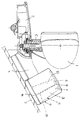
- the Drawing shows partly in side view and partly on average an interior rear view mirror according to the invention.
- the interior rearview mirror 1 is known with a foot 2 Way on the inside of the roof of a motor vehicle attached. From the mirror base 2 stands down a carrier 3 from which the inside rear view mirror 1 is attached is. The foot 2 extends in the direction of travel of the vehicle forwards and backwards over the carrier 3. The part of the foot 2 projecting forward is an intermediate piece 4 that on the inside of a windshield 5 of the motor vehicle is present.
- the intermediate piece 4 connects a housing 6 to the foot 2.
- the housing 6 can be attached to adapter 4 by gluing, locking, screwing, Be stuck or the like. It is also possible, to form the housing 6 in one piece with the intermediate piece 4.
- An infrared transmitter 7 is accommodated in the housing 6, who sits on a circuit board 8. On her also sits an infrared receiver 9, with the in still signals to be described can be received. To impair the IR receiver 9 by the Avoid transmitter 7 is one between the two components Partition 10 provided.
- the transmitter 7 and the receiver 9 are located in a recording room 11 inside the housing 6. This recording space 11 is advantageous in the direction of the windshield 5 extended training.
- the Housing 6 has a cover 14, which is preferably detachable is connected to the housing 6. This is the electronics within the housing 6 easily accessible and can be repaired or replaced if necessary.
- the Cover 14 is for the infrared radiation emitted by transmitter 7 permeable, so that the receiver 9 receives the corresponding infrared signals.
- the transmitter 7 and the receiver 9 form the motor vehicle side Part of a traffic management system with which it is possible corresponding to the motor vehicle or the driver Information while driving or at To bring the motor vehicle to a standstill.
- Traffic control systems are known and are therefore not explained in detail. These traffic control systems rely on that, for example, within a city Markers are provided which are aimed by the transmitter 7 can be. The reflected infrared signals are caught by the receiver 9, whereby the device 7, 9 receives information about where the motor vehicle is located within the urban area.
- the electronics, the transmitter 7 and the receiver 9 within of the housing 6 are housed and this housing Is part of the mirror mount, they must Parts not separately housed in the motor vehicle will.
- the intermediate piece 4 and Foot 2 is the electrical connections to the circuit board 8 simply lay inside the motor vehicle.
- Deviating from the illustrated embodiment can the circuit board 8, the transmitter 7 and the receiver 9 also housed in the intermediate piece 4 of the mirror holder be. In this case, the housing 6 is not necessary.
- An electronic can also be placed in the mirror holder Facility to be associated with an intended toll system is to be used.
- the appropriate facility with which the vehicle over the toll system can be recognized is also advantageous housed in the housing 6 of the mirror holder.
- this facility can also be provided in the intermediate piece 4.
- This facility can also be used together with the traffic control system be provided. Both facilities can housed in the housing 6 or in the intermediate piece 4 be. It is also possible to set up a facility in the housing 6 and the other device in the intermediate piece 4 to arrange. Because the mirror mount anyway is present in the motor vehicle, an additional Installation space for the facility is not required. In addition can be the corresponding via the mirror holder simply lay electrical leads in the motor vehicle.
Description
Die Erfindung betrifft eine Spiegelhalterung für einen Innenrückblickspiegel eines Kraftfahrzeuges nach dem Oberbegriff des Anspruches 1.The invention relates to a mirror holder for an interior rear view mirror of a motor vehicle according to the preamble of the claim 1.
Es sind bereits Verkehrsleitsysteme im Einsatz, die es dem Fahrer eines Kraftfahrzeuges ermöglichen, seine augenblickliche Position beispielsweise innerhalb einer Stadt zu erkennen oder zu einer gewünschten Straße oder dgl. zu finden. Auf den Straßen befinden sich entsprechende Markierungen, beispielsweise in Form von Baken, die mit einer Sende/Empfangseinheit, die im Kraftfahrzeug untergebracht ist, angepeilt werden. Mit Hilfe dieser Markierungen läßt sich einfach die augenblickliche Lage des Kraftfahrzeuges bestimmen. Die Sende/Empfangseinheit ist an der Windschutzscheibe des Kraftfahrzeuges angeklebt. Die elektrischen Leitungen für die Sende/Empfangseinheiten müssen ebenfalls an der Windschutzscheibe befestigt werden. Dies ist mit einem erheblichen Aufwand verbunden.Traffic control systems are already in use to help the driver allow a motor vehicle its current position for example recognizable within a city or to a desired one Street or the like. Are on the streets appropriate markings, for example in the form of beacons, the one with a transceiver unit in the motor vehicle is accommodated. With the help of these markings the current position of the motor vehicle can easily be determined. The transmitter / receiver unit is on the windshield glued to the motor vehicle. The electrical lines for the Transmitter / receiver units must also be on the windshield be attached. This is with a lot of effort connected.
Es ist auch bekannt (US-A-4 930 742), an einer Spiegelhalterung für einen Innenrückblickspiegel eines Kraftfahrzeuges eine Sende/Empfangseinheit eines Verkehrsleitsystems anzubringen. Die Sende/Empfangseinheit hat ein Gehäuse, das an der Unterseite eines Stützkörpers der Spiegelhalterung befestigt wird. Da die Sende/Empfangseinheit an die Spiegelhalterung angesetzt wird, benötigt der Innenrückblickspiegel erheblichen Einbauraum. Zum Ansetzen an die Spiegelhalterung ist zudem eine besondere konstruktive Ausbildung der Wand der Spiegelhalterung erforderlich. Beim Senden und Empfangen können jedoch Störungen auftreten, so daß dem Fahrer die vom Verkehrsleitsystem ausgehenden Informationen nicht einwandfrei zugehen.It is also known (US-A-4 930 742) on a mirror mount for an interior rearview mirror of a motor vehicle a transmitting / receiving unit to install a traffic control system. The Transmitter / receiver unit has a housing that is on the underside of a Support body of the mirror bracket is attached. Since the sending / receiving unit is attached to the mirror holder the interior rear view mirror considerable installation space. To start with there is also a special design to the mirror holder Training of the wall of the mirror holder required. On sending However, interference and reception may occur, so that the driver the information coming from the traffic management system not approach properly.
Der Erfindung liegt die Aufgabe zugrunde, eine Spiegelhalterung dieser Art so auszubilden, daß eine optimale Funktionsfähigkeit der Sende/Empfangseinheit bei kleinem Platzbedarf und einfacher konstruktiver Gestaltung gewährleistet ist.The invention has for its object a mirror holder of this type so that an optimal functionality of the Transmitter / receiver unit with a small footprint and simple design Design is guaranteed.
Diese Aufgabe wird bei einer Spiegelhalterung der gattungsbildenden Art erfindungsgemäß mit den kennzeichnenden Merkmalen des Anspruches 1 gelöst.This task is the generic type in a mirror mount Art according to the invention with the characteristic features of Claim 1 solved.
Durch die erfindungsgemäße Ausbildung der Aufnahme können die Sendesignale der Sende/Empfangseinheit ungehindert aus- und eintreten. Infolge der Unterteilung der Aufnahme befinden sich Sender und Empfänger in getrennten Räumen, wodurch die Sendesignale durch die Empfangssignale nicht beeinträchtigt werden können. Dadurch wird eine optimale Sende- und Empfangsqualität gewährleistet, so daß Informationen vom Verkehrsleitsystem einwandfrei an den Fahrer weitergegeben werden können. Die Sende/Empfangseinheit ist in der Spiegelhalterung untergebracht, so daß zusätzlicher Raum für die Sende/Empfangseinheit nicht benötigt wird. Auch ist eine besondere konstruktive Gestaltung der Einheit und/oder der Spiegelhalterung nicht erforderlich. The inventive design of the recording can Transmit signals from the transmitter / receiver unit unhindered enter. As a result of the division of the recording are Transmitter and receiver in separate rooms, reducing the transmission signals are not affected by the received signals can. This ensures an optimal transmission and reception quality ensures that information from the traffic control system is flawless can be passed on to the driver. The sending / receiving unit is housed in the mirror holder, so that additional space for the transmitter / receiver unit is not required becomes. There is also a special constructive design of the unit and / or the mirror mount is not required.
Bei einer bevorzugten Ausführungsform ist die Sende/Empfangseinheit eine IR-Sende/Empfangseinheit. Selbstverständlich kann die Sende/Empfangseinheit auch mit anderen Signalen, beispielsweise mit Ultraschall arbeiten. Grundsätzlich ist jede geeignete Ausbildung möglich.In a preferred embodiment, the transmitting / receiving unit an IR transmitter / receiver unit. Of course you can the transmitter / receiver unit also with other signals, for example work with ultrasound. Basically any suitable one Training possible.
Bei einer anderen Ausführungsform ist die Spiegelhalterung mit mindestens einer Aufnahme versehen, in der wenigstens eine Sende/Empfangseinheit eines elektronischen Mautsystems untergebracht ist. Dieses Mautsystem soll auf Autobahnen eingesetzt werden, um die Autobahngebühren für jedes die Autobahn benutzende Kraftfahrzeug zu ermitteln. Die hierfür benötigten Sende/Empfangseinheiten lassen sich in der Aufnahme der Spiegelhalterung einfach und geschützt unterbringen.In another embodiment, the mirror holder is included provided at least one receptacle in the at least one transmitting / receiving unit an electronic toll system is. This toll system is to be used on motorways, around the freeway tolls for everyone using the freeway Determine motor vehicle. The send / receive units required for this can easily be accommodated in the mirror holder and sheltered.
Bei einer bevorzugten Ausführungsform ist die Spiegelhalterung sowohl mit der Sende/Empfangseinheit für das Verkehrsleitsystem als auch mit der Sende/Empfangseinheit für das Mautsystem versehen. Beide Sende/Empfangseinheiten sind vorteilhaft in einer gemeinsamen Aufnahme der Spiegelhalterung untergebracht.In a preferred embodiment, the mirror holder both with the transmitter / receiver unit for the traffic control system as well as the transmitter / receiver unit for the toll system. Both transmitter / receiver units are advantageously in one Accommodation of the mirror holder housed.
Auch die Sende/Empfangseinheit für das elektronische Mautsystem ist an die Fahrzeugbatterie zur Stromversorgung angeschlossen.Also the transmitter / receiver unit for the electronic toll system is connected to the vehicle battery for power supply.
Die erfindungsgemäße Spiegelhalterung weist vorteilhaft ein Gehäuse auf, in dem sich die Aufnahme für die Sende/Empfangseinheit befindet.The mirror holder according to the invention advantageously has a housing in which the recording for the transmitter / receiver unit located.
Dieses Gehäuse ist vorteilhaft mit dem Fuß der Spiegelhalterung verbunden, vorzugsweise einstückig mit ihm ausgebildet. Dadurch kann die Spiegelhalterung zusammen mit dem Gehäuse in einem Arbeitsgang hergestellt und montiert werden. Es ist nicht erforderlich, das Gehäuse gesondert zu montieren.This housing is advantageous with the base of the mirror holder connected, preferably integrally formed with it. Thereby can the mirror holder together with the housing in one Work step can be manufactured and assembled. It is not necessary, to mount the housing separately.
Bei einer bevorzugten Ausführungsform ist das Gehäuse über ein Zwischenstück mit dem Fuß verbunden. Das Zwischenstück kann so ausgebildet werden, daß das Gehäuse und die darin befindliche Sende/Empfangseinheit an einer für ihre Funktion geeigneten Stelle an der Windschutzscheibe des Kraftfahrzeuges liegen.In a preferred embodiment, the housing is over a Intermediate piece connected to the foot. The intermediate piece can do so be formed that the housing and the one located therein Transmitter / receiver unit at a suitable one for its function Place on the windshield of the motor vehicle.
Damit der Innenrückblickspiegel mit dem Gehäuse nicht kollidiert, steht vom Fuß ein Träger ab, an dem der Innenrückblickspiegel angeordnet ist.So that the interior rearview mirror does not collide with the housing, a bracket protrudes from the foot on which the interior rear-view mirror is arranged is.
Um die Sende/Empfangseinheit optimal im Gehäuse zu schützen, ist es mit einer Abdeckung versehen. Sie ist so ausgebildet, daß die Sende/Empfangssignale der Sende/Empfangseinheit durch die Abdeckung ungehindert durchtreten können.To optimally protect the transmitter / receiver unit in the housing, it has a cover. It is designed so that the transmission / reception signals of the transmission / reception unit by the Cover can pass through unhindered.
Um die Sende/Empfangseinheit einfach montieren zu können, ist die Abdeckung vorteilhaft lösbar mit dem Gehäuse verbunden. Dadurch besteht auch die Möglichkeit, die Sende/Empfangseinheit im Bedarfsfalle leicht reparieren und/oder austauschen zu können.In order to be able to easily assemble the transmitter / receiver unit, the cover is advantageously detachably connected to the housing. Thereby there is also the possibility of the transmitter / receiver unit in the To be able to easily repair and / or replace the need trap.
In der Aufnahme ist vorteilhaft auch die Leiterplatte untergebracht, auf der der Sender und der Empfänger der Sende/Empfangseinheit sitzen.The circuit board is advantageously also accommodated in the receptacle, on which the transmitter and the receiver of the transmitter / receiver unit to sit.
Damit die Sendesignale der Sende/Empfangseinheit ungehindert aus dem Gehäuse austreten können, ist die Aufnahme in Senderichtung der Sende/Empfangseinheit erweitert ausgebildet. So that the transmission signals of the transmitter / receiver unit are unimpeded can emerge from the housing, is the recording in the direction of transmission the transmitter / receiver unit has been expanded.
Weitere Merkmale der Erfindung ergeben sich aus den weiteren Ansprüchen, der Beschreibung und der Zeichnung.Further features of the invention result from the others Claims, the description and the drawing.
Die Erfindung wird anhand eines in der Zeichnung dargestellten Ausführungsbeispieles näher erläutert. Die Zeichnung zeigt teilweise in Seitenansicht und teilweise im Schnitt einen erfindungsgemäßen Innenrückblickspiegel.The invention is illustrated by one in the drawing Embodiment explained in more detail. The Drawing shows partly in side view and partly on average an interior rear view mirror according to the invention.
Der Innenrückblickspiegel 1 ist mit einem Fuß 2 in bekannter
Weise an der Innenseite des Daches eines Kraftfahrzeuges
befestigt. Vom Spiegelfuß 2 steht nach unten
ein Träger 3 ab, an dem der Innenrückblickspiegel 1 befestigt
ist. Der Fuß 2 erstreckt sich in Fahrtrichtung
des Fahrzeuges nach vorn und hinten über den Träger 3.
Der nach vorn überstehende Teil des Fußes 2 ist ein Zwischenstück
4, das an der Innenseite einer Windschutzscheibe
5 des Kraftfahrzeuges anliegt. Das Zwischenstück
4 verbindet ein Gehäuse 6 mit dem Fuß 2. Das Gehäuse 6
kann am Zwischenstück 4 durch Kleben, Rasten, Schrauben,
Stecken oder dgl. befestigt sein. Es ist auch möglich,
das Gehäuse 6 einstückig mit dem Zwischenstück 4 auszubilden.
Im Gehäuse 6 ist ein Infrarotsender 7 untergebracht,
der auf einer Leiterplatte 8 sitzt. Auf ihr
sitzt außerdem ein Infrarotempfänger 9, mit dem in noch
zu beschreibender Weise Signale empfangen werden können.
Um eine Beeinträchtigung des IR-Empfängers 9 durch den
Sender 7 zu vermeiden, ist zwischen beiden Bauteilen eine
Zwischenwand 10 vorgesehen.The interior rearview mirror 1 is known with a
Der Sender 7 und der Empfänger 9 liegen in einem Aufnahmeraum
11 innerhalb des Gehäuses 6. Dieser Aufnahmeraum
11 ist vorteilhaft in Richtung auf die Windschutzscheibe
5 erweitert ausgebildet. Durch die Zwischenwand 10 wird
er in zwei Bereiche 12 und 13 unterteilt, in denen der
Sender 7 bzw. der Empfänger 9 untergebracht sind. Das
Gehäuse 6 hat eine Abdeckung 14, die vorzugsweise lösbar
mit dem Gehäuse 6 verbunden ist. Dadurch ist die Elektronik
innerhalb des Gehäuses 6 einfach zugänglich und
kann bei Bedarf repariert bzw. ausgetauscht werden. Die
Abdeckung 14 ist für die vom Sender 7 ausgesandte Infrarotstrahlung
durchlässig, so daß auch der Empfänger 9
die entsprechenden Infrarotsignale erhält.The
Der Sender 7 und der Empfänger 9 bilden den kraftfahrzeugseitigen
Teil eines Verkehrsleitsystems, mit dem es
möglich ist, dem Kraftfahrzeug bzw. dem Fahrer entsprechende
Informationen während der Fahrt oder auch bei
Stillstand des Kraftfahrzeuges zukommen zu lassen. Solche
Verkehrsleitsysteme sind bekannt und werden darum
nicht im einzelnen erläutert. Diese Verkehrsleitsysteme
beruhen darauf, daß beispielsweise innerhalb einer Stadt
Markierungen vorgesehen sind, die vom Sender 7 angepeilt
werden können. Die reflektierten Infrarotsignale werden
vom Empfänger 9 aufgefangen, wodurch die Einrichtung 7,
9 Informationen darüber erhält, wo sich das Kraftfahrzeug
innerhalb des Stadtgebietes befindet.The
Da die Elektronik, der Sender 7 und der Empfänger 9 innerhalb
des Gehäuses 6 untergebracht sind und dieses Gehäuse
Bestandteil der Spiegelhalterung ist, müssen diese
Teile nicht gesondert im Kraftfahrzeug untergebracht
werden. Über das Gehäuse 6, das Zwischenstück 4 und den
Fuß 2 lassen sich die elektrischen Verbindungen zur Leiterplatte
8 einfach innerhalb des Kraftfahrzeuges verlegen.Since the electronics, the
Abweichend vom dargestellten Ausführungsbeispiel können
die Leiterplatte 8, der Sender 7 und der Empfänger 9
auch im Zwischenstück 4 der Spiegelhalterung untergebracht
sein. In diesem Falle ist das Gehäuse 6 nicht erforderlich.Deviating from the illustrated embodiment can
the
In der Spiegelhalterung kann auch eine elektronische
Einrichtung untergebracht sein, die in Verbindung mit
einem beabsichtigten Mautsystem eingesetzt werden soll.
Die entsprechende Einrichtung, mit der das Fahrzeug über
das Mautsystem erkannt werden kann, ist ebenfalls vorteilhaft
im Gehäuse 6 der Spiegelhalterung untergebracht.
Ebenso ist es aber auch möglich, diese Einrichtung
im Zwischenstück 4 vorzusehen. Diese Einrichtung
kann darüberhinaus zusammen mit der Verkehrsleitsystem-Einrichtung
vorgesehen sein. Beide Einrichtungen können
im Gehäuse 6 oder im Zwischenstück 4 untergebracht
sein. Ebenso ist es aber auch möglich, die eine Einrichtung
im Gehäuse 6 und die andere Einrichtung im Zwischenstück
4 anzuordnen. Da die Spiegelhalterung ohnehin
im Kraftfahrzeug vorhanden ist, wird ein zusätzlicher
Einbauraum für die Einrichtung nicht benötigt. Zudem
lassen sich über die Spiegelhalterung die entsprechenden
elektrischen Zuleitungen einfach im Kraftfahrzeug verlegen.An electronic can also be placed in the mirror holder
Facility to be associated with
an intended toll system is to be used.
The appropriate facility with which the vehicle over
the toll system can be recognized is also advantageous
housed in the housing 6 of the mirror holder.
However, it is also possible to use this facility
to be provided in the
Claims (9)
- A mirror mounting for an internal rear-view mirror (1) of a motor vehicle, with a base (2) connected to the internal rear-view mirror (1), and with at least one transmitting and receiving unit (7, 9) of a traffic-management system, characterized in that the transmitting and receiving unit (7, 9) is housed in a holding means (11) provided in the mirror mounting and divided by a partition wall (10) into a holding space (12) for a transmitter (7) and a farther holding space (13) for a receiver (9) of the transmitting and receiving unit (7, 9).
- A mirror mounting according to Claim 1, characterized in that the transmitting and receiving unit (7, 9) is an IR transmitting and receiving unit.
- A minor mounting according to Claim 1 or 2, characterized in that the mirror mounting has at least one holding means (11) for at least one transmitting and receiving unit of an electronic toll system.
- A mirror mounting according to Claim 3, characterized in that the transmitting and receiving unit of the traffic-management system and of the toll system are housed in a common holding means.
- A mirror mounting according to one of Claims 1 to 4, characterized in that the holding means (11) is provided in a housing (6) of the mirror mounting which is preferably connected to the base (2) by way of an intermediate member (4).
- A mirror mounting according to one of Claims 1 to 5, characterized in that a support (3), on which the internal rear-view mirror (1) is mounted, projects from the base (2).
- A mirror mounting according to Claim 5 to 6, characterized in that the housing (6) is provided with a covering (14) which is preferably arranged in a detachable manner and through which the transmitted and received signals of the transmitting and receiving unit (7, 9) pass.
- A mirror mounting according to one of Claims 1 to 7, characterized in that a printed circuit board (8), on which the transmitter (7) and the receiver (9) of the transmitting and receiving unit (7, 9) are mounted, is housed in the holding means (11).
- A mirror mounting according to one of Claims 1 to 8, characterized in that the holding means (11) is enlarged in the transmitting direction of the transmitting and receiving unit (7, 9).
Applications Claiming Priority (2)
| Application Number | Priority Date | Filing Date | Title |
|---|---|---|---|
| DE9406204U DE9406204U1 (en) | 1994-04-14 | 1994-04-14 | Mirror holder for an interior rear view mirror of a motor vehicle |
| DE9406204U | 1994-04-14 |
Publications (2)
| Publication Number | Publication Date |
|---|---|
| EP0677428A1 EP0677428A1 (en) | 1995-10-18 |
| EP0677428B1 true EP0677428B1 (en) | 1998-06-10 |
Family
ID=6907322
Family Applications (1)
| Application Number | Title | Priority Date | Filing Date |
|---|---|---|---|
| EP95104265A Expired - Lifetime EP0677428B1 (en) | 1994-04-14 | 1995-03-23 | Mirror mount for an internal rearview mirror of a motor vehicle |
Country Status (3)
| Country | Link |
|---|---|
| EP (1) | EP0677428B1 (en) |
| DE (2) | DE9406204U1 (en) |
| ES (1) | ES2116639T3 (en) |
Cited By (14)
| Publication number | Priority date | Publication date | Assignee | Title |
|---|---|---|---|---|
| US8710969B2 (en) | 2004-08-18 | 2014-04-29 | Magna Electronics Inc. | Accessory system for vehicle |
| US8749367B2 (en) | 1999-11-04 | 2014-06-10 | Magna Electronics Inc. | Driver assistance system for a vehicle |
| US8818042B2 (en) | 2004-04-15 | 2014-08-26 | Magna Electronics Inc. | Driver assistance system for vehicle |
| US8842176B2 (en) | 1996-05-22 | 2014-09-23 | Donnelly Corporation | Automatic vehicle exterior light control |
| US8917169B2 (en) | 1993-02-26 | 2014-12-23 | Magna Electronics Inc. | Vehicular vision system |
| US8926151B2 (en) | 1997-08-25 | 2015-01-06 | Magna Electronics Inc. | Vehicular accessory system |
| US8993951B2 (en) | 1996-03-25 | 2015-03-31 | Magna Electronics Inc. | Driver assistance system for a vehicle |
| US9035233B2 (en) | 1997-08-25 | 2015-05-19 | Magna Electronics Inc. | Accessory mounting system for mounting an electronic device at a windshield of a vehicle |
| US9090213B2 (en) | 2004-12-15 | 2015-07-28 | Magna Electronics Inc. | Accessory mounting system for a vehicle |
| US9233645B2 (en) | 1999-11-04 | 2016-01-12 | Magna Electronics Inc. | Accessory mounting system for a vehicle |
| US9283900B2 (en) | 1999-08-25 | 2016-03-15 | Magna Electronics Inc. | Accessory mounting system for a vehicle |
| US9436880B2 (en) | 1999-08-12 | 2016-09-06 | Magna Electronics Inc. | Vehicle vision system |
| US9434314B2 (en) | 1998-04-08 | 2016-09-06 | Donnelly Corporation | Electronic accessory system for a vehicle |
| US9555803B2 (en) | 2002-05-03 | 2017-01-31 | Magna Electronics Inc. | Driver assistance system for vehicle |
Families Citing this family (6)
| Publication number | Priority date | Publication date | Assignee | Title |
|---|---|---|---|---|
| DE19602578A1 (en) * | 1996-01-25 | 1997-07-31 | Mekra Lang Gmbh & Co Kg | Exterior rear view mirror for motor vehicles, in particular commercial vehicles |
| US5798882A (en) * | 1996-03-22 | 1998-08-25 | Sabine Lang | Rear-view mirror assembly with internal antenna mount |
| DE29713582U1 (en) * | 1997-07-31 | 1997-10-02 | Kostal Leopold Gmbh & Co Kg | Motor vehicle with one or more systems for processing information |
| US6824281B2 (en) | 2002-01-31 | 2004-11-30 | Donnelly Corporation | Vehicle accessory module |
| WO2008024639A2 (en) | 2006-08-11 | 2008-02-28 | Donnelly Corporation | Automatic headlamp control system |
| CN109131094A (en) * | 2018-10-08 | 2019-01-04 | 潘陈斐 | A kind of auto mirror base device of quick release installation |
Family Cites Families (3)
| Publication number | Priority date | Publication date | Assignee | Title |
|---|---|---|---|---|
| US4930742A (en) * | 1988-03-25 | 1990-06-05 | Donnelly Corporation | Rearview mirror and accessory mount for vehicles |
| WO1994000921A1 (en) * | 1992-06-25 | 1994-01-06 | Nippondenso Co., Ltd. | Mobile object identification device |
| DE4322937A1 (en) * | 1993-07-09 | 1995-01-12 | Hohe Kg | Information device in a motor vehicle |
-
1994
- 1994-04-14 DE DE9406204U patent/DE9406204U1/en not_active Expired - Lifetime
-
1995
- 1995-03-23 ES ES95104265T patent/ES2116639T3/en not_active Expired - Lifetime
- 1995-03-23 EP EP95104265A patent/EP0677428B1/en not_active Expired - Lifetime
- 1995-03-23 DE DE59502456T patent/DE59502456D1/en not_active Expired - Fee Related
Cited By (24)
| Publication number | Priority date | Publication date | Assignee | Title |
|---|---|---|---|---|
| US8917169B2 (en) | 1993-02-26 | 2014-12-23 | Magna Electronics Inc. | Vehicular vision system |
| US8993951B2 (en) | 1996-03-25 | 2015-03-31 | Magna Electronics Inc. | Driver assistance system for a vehicle |
| US8842176B2 (en) | 1996-05-22 | 2014-09-23 | Donnelly Corporation | Automatic vehicle exterior light control |
| US9035233B2 (en) | 1997-08-25 | 2015-05-19 | Magna Electronics Inc. | Accessory mounting system for mounting an electronic device at a windshield of a vehicle |
| US8926151B2 (en) | 1997-08-25 | 2015-01-06 | Magna Electronics Inc. | Vehicular accessory system |
| US9527445B2 (en) | 1998-01-07 | 2016-12-27 | Magna Electronics Inc. | Accessory mounting system for mounting an accessory at a vehicle such that a camera views through the vehicle windshield |
| US9434314B2 (en) | 1998-04-08 | 2016-09-06 | Donnelly Corporation | Electronic accessory system for a vehicle |
| US9436880B2 (en) | 1999-08-12 | 2016-09-06 | Magna Electronics Inc. | Vehicle vision system |
| US9446715B2 (en) | 1999-08-25 | 2016-09-20 | Magna Electronics Inc. | Vision system for a vehicle |
| US9283900B2 (en) | 1999-08-25 | 2016-03-15 | Magna Electronics Inc. | Accessory mounting system for a vehicle |
| US9539956B2 (en) | 1999-08-25 | 2017-01-10 | Magna Electronics Inc. | Accessory system for a vehicle |
| US8749367B2 (en) | 1999-11-04 | 2014-06-10 | Magna Electronics Inc. | Driver assistance system for a vehicle |
| US9193302B2 (en) | 1999-11-04 | 2015-11-24 | Magna Electronics Inc. | Vision system for a vehicle |
| US9233645B2 (en) | 1999-11-04 | 2016-01-12 | Magna Electronics Inc. | Accessory mounting system for a vehicle |
| US10059265B2 (en) | 2000-03-02 | 2018-08-28 | Magna Electronics Inc. | Vision system for a vehicle |
| US9555803B2 (en) | 2002-05-03 | 2017-01-31 | Magna Electronics Inc. | Driver assistance system for vehicle |
| US9428192B2 (en) | 2004-04-15 | 2016-08-30 | Magna Electronics Inc. | Vision system for vehicle |
| US8818042B2 (en) | 2004-04-15 | 2014-08-26 | Magna Electronics Inc. | Driver assistance system for vehicle |
| US9008369B2 (en) | 2004-04-15 | 2015-04-14 | Magna Electronics Inc. | Vision system for vehicle |
| US9191634B2 (en) | 2004-04-15 | 2015-11-17 | Magna Electronics Inc. | Vision system for vehicle |
| US8710969B2 (en) | 2004-08-18 | 2014-04-29 | Magna Electronics Inc. | Accessory system for vehicle |
| US9266474B2 (en) | 2004-08-18 | 2016-02-23 | Magna Electronics Inc. | Accessory system for vehicle |
| US9090213B2 (en) | 2004-12-15 | 2015-07-28 | Magna Electronics Inc. | Accessory mounting system for a vehicle |
| US10046714B2 (en) | 2004-12-15 | 2018-08-14 | Magna Electronics Inc. | Accessory mounting system for a vehicle |
Also Published As
| Publication number | Publication date |
|---|---|
| DE9406204U1 (en) | 1994-06-23 |
| EP0677428A1 (en) | 1995-10-18 |
| ES2116639T3 (en) | 1998-07-16 |
| DE59502456D1 (en) | 1998-07-16 |
Similar Documents
| Publication | Publication Date | Title |
|---|---|---|
| EP0677428B1 (en) | Mirror mount for an internal rearview mirror of a motor vehicle | |
| DE19538770B4 (en) | Exterior rearview mirror for vehicles, preferably for motor vehicles | |
| EP2186684B1 (en) | Load carrier and vehicular coupling device | |
| EP1573679B1 (en) | Infrared (ir) communication device for motor vehicles | |
| DE4309492C1 (en) | Internal roof-bracket for motor vehicles, in particular for utility vehicles derived from passenger vehicles | |
| DE10338756B4 (en) | Headlight system of a motor vehicle | |
| DE10035124B4 (en) | Electronic distance warning system | |
| EP0896906B1 (en) | Vehicle electric installation supply device | |
| EP0673802A1 (en) | Supervisory apparatus for the driver and/or passenger of vehicles, preferably heavy vehicles | |
| EP1300287A2 (en) | Device and method for determining the inclination of a vehicle and controlling the lighting distance | |
| DE3322528A1 (en) | Monitoring device for a rear blind spot in a motor vehicle | |
| DE4405755A1 (en) | Direction indicators for road vehicle | |
| DE102007010291B4 (en) | A system for wireless transmission of a control signal to a receiving unit | |
| DE202007016780U1 (en) | Reversing aid, especially for trailers | |
| EP0361104A2 (en) | Arrangement at motor vehicle exterior parts | |
| EP1423298B1 (en) | Electronic distance warning system | |
| DE10050002A1 (en) | Monitoring system for a road vehicle uses output from video cameras located at each corner | |
| DE10210101A1 (en) | Electronic distance warning system | |
| DE3225407A1 (en) | Warning device for installation on motor vehicles | |
| EP1304262A2 (en) | Interior light for vehicle | |
| DE202023106722U1 (en) | Saddle with radar detection and warning device | |
| EP0757945A2 (en) | Agricultural vehicle | |
| DE10239840A1 (en) | Mounting for sensor in motor vehicle lamp has cut out in light lens to receive sensor mounted in holder | |
| DE10313569A1 (en) | Rearview mirror for vehicles, preferably motor vehicles | |
| DE102007036152B4 (en) | Housing for a fixed station of a robot system formed in particular by a dust collection robot system |
Legal Events
| Date | Code | Title | Description |
|---|---|---|---|
| PUAI | Public reference made under article 153(3) epc to a published international application that has entered the european phase |
Free format text: ORIGINAL CODE: 0009012 |
|
| AK | Designated contracting states |
Kind code of ref document: A1 Designated state(s): BE DE ES FR GB IT LU NL SE |
|
| 17P | Request for examination filed |
Effective date: 19960417 |
|
| 17Q | First examination report despatched |
Effective date: 19961021 |
|
| GRAG | Despatch of communication of intention to grant |
Free format text: ORIGINAL CODE: EPIDOS AGRA |
|
| GRAH | Despatch of communication of intention to grant a patent |
Free format text: ORIGINAL CODE: EPIDOS IGRA |
|
| ITF | It: translation for a ep patent filed |
Owner name: INTERPATENT ST.TECN. BREV. |
|
| GRAH | Despatch of communication of intention to grant a patent |
Free format text: ORIGINAL CODE: EPIDOS IGRA |
|
| GRAA | (expected) grant |
Free format text: ORIGINAL CODE: 0009210 |
|
| AK | Designated contracting states |
Kind code of ref document: B1 Designated state(s): BE DE ES FR GB IT LU NL SE |
|
| PG25 | Lapsed in a contracting state [announced via postgrant information from national office to epo] |
Ref country code: NL Free format text: LAPSE BECAUSE OF FAILURE TO SUBMIT A TRANSLATION OF THE DESCRIPTION OR TO PAY THE FEE WITHIN THE PRESCRIBED TIME-LIMIT Effective date: 19980610 |
|
| GBT | Gb: translation of ep patent filed (gb section 77(6)(a)/1977) |
Effective date: 19980615 |
|
| REF | Corresponds to: |
Ref document number: 59502456 Country of ref document: DE Date of ref document: 19980716 |
|
| REG | Reference to a national code |
Ref country code: ES Ref legal event code: FG2A Ref document number: 2116639 Country of ref document: ES Kind code of ref document: T3 |
|
| PG25 | Lapsed in a contracting state [announced via postgrant information from national office to epo] |
Ref country code: SE Free format text: LAPSE BECAUSE OF FAILURE TO SUBMIT A TRANSLATION OF THE DESCRIPTION OR TO PAY THE FEE WITHIN THE PRESCRIBED TIME-LIMIT Effective date: 19980910 |
|
| ET | Fr: translation filed | ||
| NLV1 | Nl: lapsed or annulled due to failure to fulfill the requirements of art. 29p and 29m of the patents act | ||
| PLBE | No opposition filed within time limit |
Free format text: ORIGINAL CODE: 0009261 |
|
| STAA | Information on the status of an ep patent application or granted ep patent |
Free format text: STATUS: NO OPPOSITION FILED WITHIN TIME LIMIT |
|
| 26N | No opposition filed | ||
| REG | Reference to a national code |
Ref country code: GB Ref legal event code: IF02 |
|
| PGFP | Annual fee paid to national office [announced via postgrant information from national office to epo] |
Ref country code: BE Payment date: 20020328 Year of fee payment: 8 |
|
| PGFP | Annual fee paid to national office [announced via postgrant information from national office to epo] |
Ref country code: LU Payment date: 20020419 Year of fee payment: 8 |
|
| PG25 | Lapsed in a contracting state [announced via postgrant information from national office to epo] |
Ref country code: LU Free format text: LAPSE BECAUSE OF NON-PAYMENT OF DUE FEES Effective date: 20030323 |
|
| PG25 | Lapsed in a contracting state [announced via postgrant information from national office to epo] |
Ref country code: BE Free format text: LAPSE BECAUSE OF NON-PAYMENT OF DUE FEES Effective date: 20030331 |
|
| BERE | Be: lapsed |
Owner name: *REITTER & SCHEFENACKER G.M.B.H. & CO. K.G. Effective date: 20030331 |
|
| PGFP | Annual fee paid to national office [announced via postgrant information from national office to epo] |
Ref country code: ES Payment date: 20040317 Year of fee payment: 10 |
|
| PG25 | Lapsed in a contracting state [announced via postgrant information from national office to epo] |
Ref country code: ES Free format text: LAPSE BECAUSE OF NON-PAYMENT OF DUE FEES Effective date: 20050326 |
|
| REG | Reference to a national code |
Ref country code: ES Ref legal event code: FD2A Effective date: 20050326 |
|
| PGFP | Annual fee paid to national office [announced via postgrant information from national office to epo] |
Ref country code: FR Payment date: 20070301 Year of fee payment: 13 |
|
| PGFP | Annual fee paid to national office [announced via postgrant information from national office to epo] |
Ref country code: GB Payment date: 20080320 Year of fee payment: 14 |
|
| PGFP | Annual fee paid to national office [announced via postgrant information from national office to epo] |
Ref country code: DE Payment date: 20080321 Year of fee payment: 14 |
|
| PGFP | Annual fee paid to national office [announced via postgrant information from national office to epo] |
Ref country code: IT Payment date: 20080328 Year of fee payment: 14 |
|
| REG | Reference to a national code |
Ref country code: FR Ref legal event code: ST Effective date: 20081125 |
|
| REG | Reference to a national code |
Ref country code: GB Ref legal event code: 732E Free format text: REGISTERED BETWEEN 20090326 AND 20090401 |
|
| PG25 | Lapsed in a contracting state [announced via postgrant information from national office to epo] |
Ref country code: FR Free format text: LAPSE BECAUSE OF NON-PAYMENT OF DUE FEES Effective date: 20080331 |
|
| GBPC | Gb: european patent ceased through non-payment of renewal fee |
Effective date: 20090323 |
|
| PG25 | Lapsed in a contracting state [announced via postgrant information from national office to epo] |
Ref country code: DE Free format text: LAPSE BECAUSE OF NON-PAYMENT OF DUE FEES Effective date: 20091001 |
|
| PG25 | Lapsed in a contracting state [announced via postgrant information from national office to epo] |
Ref country code: GB Free format text: LAPSE BECAUSE OF NON-PAYMENT OF DUE FEES Effective date: 20090323 |
|
| PG25 | Lapsed in a contracting state [announced via postgrant information from national office to epo] |
Ref country code: IT Free format text: LAPSE BECAUSE OF NON-PAYMENT OF DUE FEES Effective date: 20090323 |