EP0677272A1 - Apparatus for viewing the interior of the large intestine - Google Patents
Apparatus for viewing the interior of the large intestine Download PDFInfo
- Publication number
- EP0677272A1 EP0677272A1 EP95301996A EP95301996A EP0677272A1 EP 0677272 A1 EP0677272 A1 EP 0677272A1 EP 95301996 A EP95301996 A EP 95301996A EP 95301996 A EP95301996 A EP 95301996A EP 0677272 A1 EP0677272 A1 EP 0677272A1
- Authority
- EP
- European Patent Office
- Prior art keywords
- viewing device
- optical viewing
- housing
- cavity
- optical
- Prior art date
- Legal status (The legal status is an assumption and is not a legal conclusion. Google has not performed a legal analysis and makes no representation as to the accuracy of the status listed.)
- Withdrawn
Links
Images


Classifications
-
- A—HUMAN NECESSITIES
- A61—MEDICAL OR VETERINARY SCIENCE; HYGIENE
- A61B—DIAGNOSIS; SURGERY; IDENTIFICATION
- A61B1/00—Instruments for performing medical examinations of the interior of cavities or tubes of the body by visual or photographical inspection, e.g. endoscopes; Illuminating arrangements therefor
- A61B1/04—Instruments for performing medical examinations of the interior of cavities or tubes of the body by visual or photographical inspection, e.g. endoscopes; Illuminating arrangements therefor combined with photographic or television appliances
- A61B1/041—Capsule endoscopes for imaging
-
- A—HUMAN NECESSITIES
- A61—MEDICAL OR VETERINARY SCIENCE; HYGIENE
- A61B—DIAGNOSIS; SURGERY; IDENTIFICATION
- A61B1/00—Instruments for performing medical examinations of the interior of cavities or tubes of the body by visual or photographical inspection, e.g. endoscopes; Illuminating arrangements therefor
- A61B1/00147—Holding or positioning arrangements
-
- A—HUMAN NECESSITIES
- A61—MEDICAL OR VETERINARY SCIENCE; HYGIENE
- A61B—DIAGNOSIS; SURGERY; IDENTIFICATION
- A61B1/00—Instruments for performing medical examinations of the interior of cavities or tubes of the body by visual or photographical inspection, e.g. endoscopes; Illuminating arrangements therefor
- A61B1/06—Instruments for performing medical examinations of the interior of cavities or tubes of the body by visual or photographical inspection, e.g. endoscopes; Illuminating arrangements therefor with illuminating arrangements
- A61B1/0607—Instruments for performing medical examinations of the interior of cavities or tubes of the body by visual or photographical inspection, e.g. endoscopes; Illuminating arrangements therefor with illuminating arrangements for annular illumination
-
- A—HUMAN NECESSITIES
- A61—MEDICAL OR VETERINARY SCIENCE; HYGIENE
- A61B—DIAGNOSIS; SURGERY; IDENTIFICATION
- A61B1/00—Instruments for performing medical examinations of the interior of cavities or tubes of the body by visual or photographical inspection, e.g. endoscopes; Illuminating arrangements therefor
- A61B1/06—Instruments for performing medical examinations of the interior of cavities or tubes of the body by visual or photographical inspection, e.g. endoscopes; Illuminating arrangements therefor with illuminating arrangements
- A61B1/0661—Endoscope light sources
- A61B1/0676—Endoscope light sources at distal tip of an endoscope
-
- A—HUMAN NECESSITIES
- A61—MEDICAL OR VETERINARY SCIENCE; HYGIENE
- A61B—DIAGNOSIS; SURGERY; IDENTIFICATION
- A61B1/00—Instruments for performing medical examinations of the interior of cavities or tubes of the body by visual or photographical inspection, e.g. endoscopes; Illuminating arrangements therefor
- A61B1/06—Instruments for performing medical examinations of the interior of cavities or tubes of the body by visual or photographical inspection, e.g. endoscopes; Illuminating arrangements therefor with illuminating arrangements
- A61B1/0661—Endoscope light sources
- A61B1/0684—Endoscope light sources using light emitting diodes [LED]
-
- A—HUMAN NECESSITIES
- A61—MEDICAL OR VETERINARY SCIENCE; HYGIENE
- A61B—DIAGNOSIS; SURGERY; IDENTIFICATION
- A61B1/00—Instruments for performing medical examinations of the interior of cavities or tubes of the body by visual or photographical inspection, e.g. endoscopes; Illuminating arrangements therefor
- A61B1/273—Instruments for performing medical examinations of the interior of cavities or tubes of the body by visual or photographical inspection, e.g. endoscopes; Illuminating arrangements therefor for the upper alimentary canal, e.g. oesophagoscopes, gastroscopes
- A61B1/2736—Gastroscopes
-
- A—HUMAN NECESSITIES
- A61—MEDICAL OR VETERINARY SCIENCE; HYGIENE
- A61B—DIAGNOSIS; SURGERY; IDENTIFICATION
- A61B1/00—Instruments for performing medical examinations of the interior of cavities or tubes of the body by visual or photographical inspection, e.g. endoscopes; Illuminating arrangements therefor
- A61B1/31—Instruments for performing medical examinations of the interior of cavities or tubes of the body by visual or photographical inspection, e.g. endoscopes; Illuminating arrangements therefor for the rectum, e.g. proctoscopes, sigmoidoscopes, colonoscopes
-
- A—HUMAN NECESSITIES
- A61—MEDICAL OR VETERINARY SCIENCE; HYGIENE
- A61B—DIAGNOSIS; SURGERY; IDENTIFICATION
- A61B5/00—Measuring for diagnostic purposes; Identification of persons
- A61B5/0002—Remote monitoring of patients using telemetry, e.g. transmission of vital signals via a communication network
- A61B5/0031—Implanted circuitry
-
- A—HUMAN NECESSITIES
- A61—MEDICAL OR VETERINARY SCIENCE; HYGIENE
- A61B—DIAGNOSIS; SURGERY; IDENTIFICATION
- A61B1/00—Instruments for performing medical examinations of the interior of cavities or tubes of the body by visual or photographical inspection, e.g. endoscopes; Illuminating arrangements therefor
- A61B1/06—Instruments for performing medical examinations of the interior of cavities or tubes of the body by visual or photographical inspection, e.g. endoscopes; Illuminating arrangements therefor with illuminating arrangements
Definitions
- the present invention relates to a method and apparatus for viewing the interior surfaces of a cavity.
- the invention is particularly useful for viewing the interior surfaces of a subject's intestine, and is therefore described below particularly with respect to this application.
- Colonic malignant tumor is the main cancer in the Western countries. Its precursor, the benign polyp, is formed in about 15% of the adult population. Early detection of the polyp is therefore critical for the prevention and treatment of this type of cancer.
- a common technique for colonic tumor detection is a barium enema.
- Barium sulfate is introduced as a contrast material through the anus and fills the entire large bowel.
- X-rays are used to make pictures of the whole abdominal contents, including the opaqued large bowel.
- Such a test is unpleasant, inaccurate, causes subject's inactivation, and requires the presence of a physician.
- Another technique uses a colonoscope which is inserted via the subject's anus into the colon to allow the physician to view the interior of the colon and rectum. This technique, however, not only must be performed by a physician, but is also time consuming and painful such that it frequently requires administering a pain relieving agent to the patient.
- a further technique for inspecting the interior of the colon is by ultrasound, but this method must also be performed by a physician; moreover, in its present pilot study stage, it is less accurate than the other two methods.
- a broad object of the present invention is to provide a novel method and apparatus for viewing the interior surfaces of a cavity.
- a more particular object is to provide a novel method and apparatus for visually inspecting the interior of a cavity in the human body, such as the large intestine, to enable early detection of polyps so that they can be removed while still in the benign stage, or as soon as possible after they have become malignant.
- the method and apparatus may also be used for viewing the interior of other cavities.
- a method of viewing the interior surfaces of a cavity in an object comprising: introducing into the cavity an optical viewing device including a housing containing an image transducer for converting optical images into electrical signals; manipulating the object to direct the optical viewing device by its own weight to scan the surfaces of the cavity interior to be viewed; and reconverting the electrical signals to optical images.
- the invention is particularly applicable for visually inspecting the interior surface of a cavity in the human body, such as the large intestine.
- the optical viewing device can be applied as conveniently and relatively painlessly as a suppository inserted into the rectum and can be steered to scan the interior surfaces of the large intestine by appropriately manipulating the table on which the subject is fixed.
- the optical viewing device further includes a transmitter within its housing for transmitting electrical signals from the image transducer externally of the subject, there being a video receiver in the vicinity of the subject to receive the transmitted electrical signals and to convert them to optical images for viewing in a real time manner by the attendant. It is conceivable, however, that with the rapid development of miniaturized electronic memories, the optical viewing device could also store within it the electrical signals from the image transducer and reproduce the optical images after the device has been expelled from the subject's body.
- a liquid is introduced into the cavity, e.g., the colon, in order to inflate it before introducing the optical viewing device.
- This feature better permits the optical viewing device to be steered to scan the internal surfaces of interest by manipulating the table supporting the subject in order to direct the optical viewing device through the cavity by the weight of the optical viewing device.
- the foregoing method provides a number of important advantages over the existing methods when used for visually inspecting the internal surface of a subject's intestine.
- the method may be done quickly and substantially painlessly and generally would not require the administration of a pain relieving agent.
- the procedure can also be performed by a nurse and would normally not require the presence of a physician.
- One nurse can easily administer the test to a number of patients at the same time.
- the method permits viewing the interior of the subject's intestine in a real time manner at the time the examination is made. It also permits the results of the examination to be recorded for later viewing, e.g., to enable consultation with others if desired.
- an inflatable balloon may also be introduced into the cavity in deflated condition and then inflated to retain the liquid within the cavity while the optical device scans the cavity.
- the invention also provides optical viewing devices moved by a motor included within such device, or a rod atached to the device.
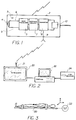
- Fig. 1 schematically illustrates an optical viewing device which includes a housing 2 made of a suitable material which can be inserted into the rectum of a subject in the manner of a suppository.
- Housing 2 is hydrodynamically shaped with all smooth surfaces so that it can move freely in both directions through the rectum and colon of the subject, as will be described more particularly below.
- the front end of the housing carries illuminating means 3, e.g., LEDs (light emitting diodes) which illuminate the tissue to be optically viewed.
- the front end of housing 2 further includes a lens 4 for receiving the light from the tissue being viewed and for focusing it on an image transducer 5, such as a CCD (charge couple device), commonly used in solid-state television cameras.
- An opaque shield 6 between focusing lens 4 and the image transducer 5 prevents stray light from being received on the image transducer.
- the image transducer 5 converts the images focused on it by focusing lens 4 into electrical signals. These electrical signals are outputted to electrical circuitry, schematically indicated at 7 within the housing 2. Electrical ciruitry 7 would include the conventional circuitry as used in solid-state television cameras to control the scanning, amplifying and modulating of the electrical signals outputted by the image transducer 5. The modulating electrical signal is then fed to a transmitter 8 within housing 2 which transmits the electrical signals externally of the subject via an antenna 9. The illustrated electrical components are powered by a self-chargeable battery 10 located within housing 2.
- Fig. 2 illustrates the equipment for receiving the electrical signals transmitted by the optical viewing device of Fig. 1. This equipment also converts such electrical signals to an optical image for real-time viewing and/or for recording to enable viewing at a later time.
- the equipment illustrated in Fig. 2 includes a television receiver 20 having an antenna 21 for receiving the electrical signals transmitted by the transmitter 8 of the optical viewing device shown in Fig. 1. Also illustrated in Fig. 2 are a computer 22 connected to the television receiver 20 in order to receive and process the information if necessary, and a video recorder 24 for recording the information if desired for later viewing.
- the optical viewing device shown in Fig. 1 may be administered to the subject via the rectum, in the manner of a suppository.
- the colon of the subject is first filled with a liquid, such as water, to inflate the colon before the device is introduced via the subject's anus.
- the subject is preferably first secured on a table, as shown at 30 in Fig. 3.
- the table may then be manipulated by a drive, schematically shown at 32, in order to orient the subject to the different positions for directing the optical viewing device by its own weight to scan the surfaces of the colon desired to be viewed.
- the electrical signals outputted by image transducer 5 are transmitted by transmitter 8 and antenna 9 externally of the subject and are received via antenna 21 of the video receiver 20 for display on the video receiver.
- the received electrical signals are also fed to computer 22 for processing if desired, and to video recorder 24 for storage to enable later viewing if desired.
- the optical viewing device illustrated in Fig. 1 may be expelled in the normal manner from the subject's body.
- the optical viewing device illustrated in Fig. 4, and therein designated 40 includes a first section 41 containing an image transducer, e.g., a CCD camera, and a transmitter; a second section 42 containing an internal battery; a third section 43 containing a motor for propelling the optical viewing device 40; and a fourth section 44 containing a control signal receiver for controlling the operation of the motor in section 43.
- Sections 41-44 are attached to each other by flexible connections 45, and are all enclosed within a flexible cover shown schematically at 46.
- the motor in section 43 propels the optical viewing device 40 in the forward direction by reaction jets discharged through openings 47 in the rear end of that section, and in the reverse direction by similar reaction jets discharged via openings 48 in the forward end of that section.
- Control of the motor is effected by signals received via the control signal receiver section 44 and transmitted from an external location, e.g., via an RF transmitter.
- the front end of the optical viewing device 40 is provided with a plurality of light sources, e.g., an annular array of LEDs, to illuminate the surfaces scanned by the CCD camera within section 41.
- section 41 may include a high-density semi-conductor storage device for storing this information, enabling the information to be read out after the optical viewing device 40 has been removed from the subject.
- the motor in section 43 propels the optical viewing device 40 either forwardly or reversely as the CCD camera 41 scans the surfaces to be inspected, e.g., the colon and rectum.
- the flexible connections 45 between the various sections permits the device as a whole to worm its way through the cavity (e.g., colon) being inspected, while the outer flexible covering 46 protects the device from body fluids as well as from the water used for inflating the body cavity being inspected.
- Fig. 5 illustrates an alternative optical viewing device, generally designated 50, which may be used.
- This device includes a front section 51 containing the CCD camera and transmitter, and a motor section 53 containing the motor for propelling the device through the body cavity.
- the device illustrated in Fig. 5, however, does not contain a battery section (corresponding to section 42, Fig. 4), or a control signal receiver section (corresponding to section 44, Fig. 4), but rather an electrical conductor 54 which supplies the electrical power and the control signals to the motor section 53 from an external source.
- Conductor 54 is flexible to permit the optical viewing device to freely travel through the cavity of the subject. It may also serve as a channel for the electrical signals transmitted from the transmitter within section 51 to an external monitoring unit.
- the optical viewing device 50 shown in Fig. 5 is constructed as described above with respect to Fig. 4, including a flexible connection 55 between the two sections 51 and 53, jet openings 57 at the rear end of section 53 for propelling the unit forwardly, jet openings 58 at the front end of section 53 for propelling the unit reversely, and an annular array of LEDs 59 at the front of the CCD camera section 51.
- Fig. 6 illustrates one form of overall apparatus that may be used for introducing the optical viewing device, generally designated 60, into the body cavity, e.g., the large intestine, to be inspected.
- the apparatus illustrated in Fig. 6 includes a hollow rectal tube 61 having a tapered front end 61a to facilitate its insertion via the subject's anus into the subject's rectum.
- the opposite end 61b of rectal tube 61 receives a connector 62 connected by a water tube 63 to a source of pressurized water 64, which water is introduced into the rectum and colon as described earlier.
- a gauge 65 measures the water pressure.
- Rectal tube 61 further includes two annular balloons 66, 67 secured to the outer surface of the tube at spaced locations along its length.
- the two balloons are in a deflated condition, but after the tube has been inserted, the two balloons are inflated by another fluid, preferably air, via an air tube 68 connected to a hand pump 69 which is to be located externally of the subject.
- pressurized water may then be introduced via water tube 63 and rectal tube 61 into the subject's rectum and colon to inflate them so that the balloons retain the water within the cavity while the cavity is inspected by the optical viewing device 60.
- Device 60 may be moved through the rectum and colon by manipulating the subject as described in Patent Application 109121, or by a propulsion system included with the optical viewing device, as described above with respect to Figs. 4 and 5.
- FIGs. 7 and 8 illustrate two possible manners of facilitating the removal of this device, and particularly for assuring that it will be properly oriented at the time of its removal.
- Fig. 7 illustrates one manner of aiding the removal of the optical viewing device 60 from the subject.
- the optical viewing device is removed from the cavity with the aid of a rod 70 passed through the rectal tube 61 and having a magnet 71 at one end to be magnetically coupled to a magnet 72 carried by the rear end of the optical viewing device 60.
- Fig. 8 illustrates a tether arrangement that may be used for removing the optical viewing device 60.
- the arrangement illustrated in Fig. 5 includes a flexible cord 80 passed through the rectal tube 61 and attached to the optical viewing device 60, so that the device can be extracted by merely pulling the cord via the rectal tube 61.
- Figs. 9 and 10 illustrate two further optical viewing devices that may be used for inspecting interior surfaces of body cavities.
- the optical viewing device illustrated in Fig. 9 includes a rod 70 having at one end an image transducer 71 for converting light images into electrical signals.
- Image transducer 71 includes the necessary optical lenses for focussing the image, and also a light source for illuminating the surface to be viewed.
- Rod 70 is of a length such that a user may grasp the rod, insert the image transducer 71 into the body cavity, and manipulate the image transducer from the opposite end, externally of the body cavity, to scan the interior surface of the cavity to be inspected.
- the opposite end of rod 70 to be disposed externally of the body cavity includes a housing 72 which houses the power supply and circitry for converting the electrical signals from the image transducer 71 to video signals. Housing 72 may also include a transmitter for transmitting the video signals to a remotely-located monitor (not shown).
- Fig. 10 illustrates a variation, also including a rod 80 carrying an image transducer 81 at one end as in Fig. 9.
- the opposite end 82 of the rod to be disposed externally of the body cavity, is connected by electrical wires 83 to a housing 84 carried by a wristband 85 to be worn by the user.
- Housing 84 on wristband 85 contains the power supply and the electrical circitry for converting the electrical signals from the image transducer 81 to video signals to be reproduced in a monitor (not shown).
- Housing 84 may also include a transmitter for transmitting the video signals to a remotely-located monitor.
Abstract
An optical viewing device (40,50) includes a housing (2,60) of a size and shape for introduction into the large intestine of a subject and for movement therein in either direction, and an image transducer (5,42,51) located within the housing for converting optical images into electrical signals. Various embodiments are described in which the housing is of a size and shape for movement by its own weight in either direction in the intestine, or in which the housing includes an electric motor (43) driving means (47,48) for propelling the housing (2,60) through the intestine, or in which the housing is carried at one end of a rod (54) of a length such that a user may grasp the opposite end and manipulate the housing to scan the interior surface of the intestine.
Description
- The present invention relates to a method and apparatus for viewing the interior surfaces of a cavity. The invention is particularly useful for viewing the interior surfaces of a subject's intestine, and is therefore described below particularly with respect to this application.
- Colonic malignant tumor is the main cancer in the Western countries. Its precursor, the benign polyp, is formed in about 15% of the adult population. Early detection of the polyp is therefore critical for the prevention and treatment of this type of cancer.
- A common technique for colonic tumor detection is a barium enema. Barium sulfate is introduced as a contrast material through the anus and fills the entire large bowel. X-rays are used to make pictures of the whole abdominal contents, including the opaqued large bowel. Such a test, however, is unpleasant, inaccurate, causes subject's inactivation, and requires the presence of a physician.
- Another technique uses a colonoscope which is inserted via the subject's anus into the colon to allow the physician to view the interior of the colon and rectum. This technique, however, not only must be performed by a physician, but is also time consuming and painful such that it frequently requires administering a pain relieving agent to the patient.
- A further technique for inspecting the interior of the colon is by ultrasound, but this method must also be performed by a physician; moreover, in its present pilot study stage, it is less accurate than the other two methods.
- A broad object of the present invention is to provide a novel method and apparatus for viewing the interior surfaces of a cavity. A more particular object is to provide a novel method and apparatus for visually inspecting the interior of a cavity in the human body, such as the large intestine, to enable early detection of polyps so that they can be removed while still in the benign stage, or as soon as possible after they have become malignant. The method and apparatus may also be used for viewing the interior of other cavities.
- According to one aspect of the present invention, there is provided a method of viewing the interior surfaces of a cavity in an object, comprising: introducing into the cavity an optical viewing device including a housing containing an image transducer for converting optical images into electrical signals; manipulating the object to direct the optical viewing device by its own weight to scan the surfaces of the cavity interior to be viewed; and reconverting the electrical signals to optical images.
- The invention is particularly applicable for visually inspecting the interior surface of a cavity in the human body, such as the large intestine. When so used, the optical viewing device can be applied as conveniently and relatively painlessly as a suppository inserted into the rectum and can be steered to scan the interior surfaces of the large intestine by appropriately manipulating the table on which the subject is fixed.
- According to further features in the preferred embodiment of the invention described below, the optical viewing device further includes a transmitter within its housing for transmitting electrical signals from the image transducer externally of the subject, there being a video receiver in the vicinity of the subject to receive the transmitted electrical signals and to convert them to optical images for viewing in a real time manner by the attendant. It is conceivable, however, that with the rapid development of miniaturized electronic memories, the optical viewing device could also store within it the electrical signals from the image transducer and reproduce the optical images after the device has been expelled from the subject's body.
- According to further features in the preferred embodiments of the invention described below, a liquid is introduced into the cavity, e.g., the colon, in order to inflate it before introducing the optical viewing device. This feature better permits the optical viewing device to be steered to scan the internal surfaces of interest by manipulating the table supporting the subject in order to direct the optical viewing device through the cavity by the weight of the optical viewing device.
- The foregoing method provides a number of important advantages over the existing methods when used for visually inspecting the internal surface of a subject's intestine. Thus, the method may be done quickly and substantially painlessly and generally would not require the administration of a pain relieving agent. The procedure can also be performed by a nurse and would normally not require the presence of a physician. One nurse can easily administer the test to a number of patients at the same time. In addition, the method permits viewing the interior of the subject's intestine in a real time manner at the time the examination is made. It also permits the results of the examination to be recorded for later viewing, e.g., to enable consultation with others if desired.
- According to further features, an inflatable balloon may also be introduced into the cavity in deflated condition and then inflated to retain the liquid within the cavity while the optical device scans the cavity.
- According to other aspects, the invention also provides optical viewing devices moved by a motor included within such device, or a rod atached to the device.
- Further features and advantages will be apparent from the description below.
- The invention is herein described, by way of example only, with reference to the accompanying drawings, wherein:
- Fig. 1 schematically illustrates one form of optical viewing device constructed in accordance with the present invention;
- Fig. 2 illustrates the external apparatus that may be used with the optical viewing device of Fig. 1;
- Fig. 3 schematically illustrates the manner of manipulating the supporting table on which the patient is fixed at the time of the test in order to steer the optical viewing device of Fig. 1 by its own weight to scan the surfaces desired to be visually inspected;
- Fig. 4 illustrates another form of optical viewing device constructed in accordance with the invention;
- Fig. 5 illustrates an alternative construction of such an optical viewing device;
- Fig. 6 illustrates another form of apparatus constructed in accordance with the invention;
- Figs. 7 and 8 are fragmentary views illustrating variations in the construction of the apparatus of Fig. 6; and
- Figs. 9 and 10 illustrate further optical viewing devices constructed in accordance with the invention.
- Fig. 1 schematically illustrates an optical viewing device which includes a
housing 2 made of a suitable material which can be inserted into the rectum of a subject in the manner of a suppository.Housing 2 is hydrodynamically shaped with all smooth surfaces so that it can move freely in both directions through the rectum and colon of the subject, as will be described more particularly below. - The front end of the housing carries illuminating means 3, e.g., LEDs (light emitting diodes) which illuminate the tissue to be optically viewed. The front end of
housing 2 further includes alens 4 for receiving the light from the tissue being viewed and for focusing it on animage transducer 5, such as a CCD (charge couple device), commonly used in solid-state television cameras. Anopaque shield 6 between focusinglens 4 and theimage transducer 5 prevents stray light from being received on the image transducer. - The
image transducer 5 converts the images focused on it by focusinglens 4 into electrical signals. These electrical signals are outputted to electrical circuitry, schematically indicated at 7 within thehousing 2.Electrical ciruitry 7 would include the conventional circuitry as used in solid-state television cameras to control the scanning, amplifying and modulating of the electrical signals outputted by theimage transducer 5. The modulating electrical signal is then fed to atransmitter 8 withinhousing 2 which transmits the electrical signals externally of the subject via anantenna 9. The illustrated electrical components are powered by a self-chargeable battery 10 located withinhousing 2. - Fig. 2 illustrates the equipment for receiving the electrical signals transmitted by the optical viewing device of Fig. 1. This equipment also converts such electrical signals to an optical image for real-time viewing and/or for recording to enable viewing at a later time. The equipment illustrated in Fig. 2 includes a
television receiver 20 having anantenna 21 for receiving the electrical signals transmitted by thetransmitter 8 of the optical viewing device shown in Fig. 1. Also illustrated in Fig. 2 are acomputer 22 connected to thetelevision receiver 20 in order to receive and process the information if necessary, and avideo recorder 24 for recording the information if desired for later viewing. - All the components illustrated in Figs. 1 and 2 are well known components, and therefore their constructions are not set forth in detal.
- It will thus be seen that the optical viewing device shown in Fig. 1 may be administered to the subject via the rectum, in the manner of a suppository. In order to direct the optical viewing device to scan the surfaces of the colon and rectum desired to be inspected, the colon of the subject is first filled with a liquid, such as water, to inflate the colon before the device is introduced via the subject's anus.
- The subject is preferably first secured on a table, as shown at 30 in Fig. 3. The table may then be manipulated by a drive, schematically shown at 32, in order to orient the subject to the different positions for directing the optical viewing device by its own weight to scan the surfaces of the colon desired to be viewed.
- As the optical viewing device is thus scanning the surfaces, the electrical signals outputted by
image transducer 5 are transmitted bytransmitter 8 andantenna 9 externally of the subject and are received viaantenna 21 of thevideo receiver 20 for display on the video receiver. The received electrical signals are also fed tocomputer 22 for processing if desired, and tovideo recorder 24 for storage to enable later viewing if desired. - After the examination has been completed, the optical viewing device illustrated in Fig. 1 may be expelled in the normal manner from the subject's body.
- The optical viewing device illustrated in Fig. 4, and therein designated 40, includes a first section 41 containing an image transducer, e.g., a CCD camera, and a transmitter; a
second section 42 containing an internal battery; athird section 43 containing a motor for propelling theoptical viewing device 40; and afourth section 44 containing a control signal receiver for controlling the operation of the motor insection 43. Sections 41-44 are attached to each other byflexible connections 45, and are all enclosed within a flexible cover shown schematically at 46. - The motor in
section 43 propels theoptical viewing device 40 in the forward direction by reaction jets discharged throughopenings 47 in the rear end of that section, and in the reverse direction by similar reaction jets discharged viaopenings 48 in the forward end of that section. Control of the motor is effected by signals received via the controlsignal receiver section 44 and transmitted from an external location, e.g., via an RF transmitter. The front end of theoptical viewing device 40 is provided with a plurality of light sources, e.g., an annular array of LEDs, to illuminate the surfaces scanned by the CCD camera within section 41. This information is transmitted via a transmitter in section 41 to a remote location; alternatively, section 41 may include a high-density semi-conductor storage device for storing this information, enabling the information to be read out after theoptical viewing device 40 has been removed from the subject. - It will thus be seen that the motor in
section 43 propels theoptical viewing device 40 either forwardly or reversely as the CCD camera 41 scans the surfaces to be inspected, e.g., the colon and rectum. Theflexible connections 45 between the various sections permits the device as a whole to worm its way through the cavity (e.g., colon) being inspected, while the outerflexible covering 46 protects the device from body fluids as well as from the water used for inflating the body cavity being inspected. - Fig. 5 illustrates an alternative optical viewing device, generally designated 50, which may be used. This device includes a
front section 51 containing the CCD camera and transmitter, and amotor section 53 containing the motor for propelling the device through the body cavity. The device illustrated in Fig. 5, however, does not contain a battery section (corresponding tosection 42, Fig. 4), or a control signal receiver section (corresponding tosection 44, Fig. 4), but rather anelectrical conductor 54 which supplies the electrical power and the control signals to themotor section 53 from an external source.Conductor 54 is flexible to permit the optical viewing device to freely travel through the cavity of the subject. It may also serve as a channel for the electrical signals transmitted from the transmitter withinsection 51 to an external monitoring unit. - In all other respects, the
optical viewing device 50 shown in Fig. 5 is constructed as described above with respect to Fig. 4, including aflexible connection 55 between the twosections jet openings 57 at the rear end ofsection 53 for propelling the unit forwardly,jet openings 58 at the front end ofsection 53 for propelling the unit reversely, and an annular array ofLEDs 59 at the front of theCCD camera section 51. - Fig. 6 illustrates one form of overall apparatus that may be used for introducing the optical viewing device, generally designated 60, into the body cavity, e.g., the large intestine, to be inspected. The apparatus illustrated in Fig. 6 includes a hollow
rectal tube 61 having a taperedfront end 61a to facilitate its insertion via the subject's anus into the subject's rectum. Theopposite end 61b ofrectal tube 61 receives aconnector 62 connected by awater tube 63 to a source ofpressurized water 64, which water is introduced into the rectum and colon as described earlier. Agauge 65 measures the water pressure. -
Rectal tube 61 further includes twoannular balloons rectal tube 61 is inserted, the two balloons are in a deflated condition, but after the tube has been inserted, the two balloons are inflated by another fluid, preferably air, via anair tube 68 connected to ahand pump 69 which is to be located externally of the subject. - After the two
annular balloons water tube 63 andrectal tube 61 into the subject's rectum and colon to inflate them so that the balloons retain the water within the cavity while the cavity is inspected by theoptical viewing device 60.Device 60 may be moved through the rectum and colon by manipulating the subject as described in Patent Application 109121, or by a propulsion system included with the optical viewing device, as described above with respect to Figs. 4 and 5. - After the inspection has been completed, the optical viewing device would normally be removable by the natural peristaltic movements of the intestine. Nevertheless, Figs. 7 and 8 illustrate two possible manners of facilitating the removal of this device, and particularly for assuring that it will be properly oriented at the time of its removal.
- Fig. 7 illustrates one manner of aiding the removal of the
optical viewing device 60 from the subject. In this case, the optical viewing device is removed from the cavity with the aid of arod 70 passed through therectal tube 61 and having amagnet 71 at one end to be magnetically coupled to amagnet 72 carried by the rear end of theoptical viewing device 60. - Fig. 8 illustrates a tether arrangement that may be used for removing the
optical viewing device 60. The arrangement illustrated in Fig. 5 includes aflexible cord 80 passed through therectal tube 61 and attached to theoptical viewing device 60, so that the device can be extracted by merely pulling the cord via therectal tube 61. - Figs. 9 and 10 illustrate two further optical viewing devices that may be used for inspecting interior surfaces of body cavities.
- The optical viewing device illustrated in Fig. 9 includes a
rod 70 having at one end animage transducer 71 for converting light images into electrical signals.Image transducer 71 includes the necessary optical lenses for focussing the image, and also a light source for illuminating the surface to be viewed.Rod 70 is of a length such that a user may grasp the rod, insert theimage transducer 71 into the body cavity, and manipulate the image transducer from the opposite end, externally of the body cavity, to scan the interior surface of the cavity to be inspected. - The opposite end of
rod 70 to be disposed externally of the body cavity includes ahousing 72 which houses the power supply and circitry for converting the electrical signals from theimage transducer 71 to video signals.Housing 72 may also include a transmitter for transmitting the video signals to a remotely-located monitor (not shown). - Fig. 10 illustrates a variation, also including a
rod 80 carrying animage transducer 81 at one end as in Fig. 9. Theopposite end 82 of the rod, to be disposed externally of the body cavity, is connected byelectrical wires 83 to ahousing 84 carried by awristband 85 to be worn by the user.Housing 84 onwristband 85 contains the power supply and the electrical circitry for converting the electrical signals from theimage transducer 81 to video signals to be reproduced in a monitor (not shown).Housing 84 may also include a transmitter for transmitting the video signals to a remotely-located monitor. - While the invention has been described with respect to one construction and one application, particularly for making colon and rectum examinations, it is to be appreciated that this is merely one example of an application of the invention, and that the invention may be used in other applications. Many other variations and applications of the invention will be apparent.
Claims (20)
- A method of viewing the interior surfaces of a cavity in an object, comprising: introducing into said cavity an optical viewing device including a housing containing an image transducer for converting optical images into electrical signals; manipulating the object to direct the optical viewing device by its own weight to scan the surfaces of the cavity interior to be viewed; and reconverting said electrical signals to optical images.
- The method according to Claim 1, wherein said electrical signals are reconverted to optical images by transmitting the electrical signals from said image transducer externally of the object; receiving said transmitted electrical signals; and converting said electrical signals to optical images.
- The method according to Claim 1, wherein said optical viewing device further includes an artificial light source for illuminating said cavity interior surfaces to be viewed.
- The method according to Claim 1, wherein said cavity is filled with a liquid before introducing said optical viewing device therein.
- The method according to Claim 4, wherein said cavity is defined by a deformable wall, and said cavity is filled with said liquid to inflate said wall before introducing said optical viewing device therein.
- A method of visually inspecting the interior surface of a body cavity, particularly the large intestine, of a subject, comprising: introducing into the subject's large intestine, via the anus, an optical viewing device including a housing containing an artificial light source for illuminating the surface to be inspected, an image transducer for converting optical images into electrical signals, and a focusing lens for focusing the optical images onto the image transducer; moving the optical viewing device to scan the surface to be inspected; and reconverting said electrical signals of the image transducer to optical images.
- The method according to Claim 6, wherein said optical viewing device is moved through the large intestine by manipulating the subject to different orientations to cause the optical viewing device to move by its own weight.
- The method according to Claim 6, wherein said optical viewing device is moved through the large intestine by a motor included in said optical viewing device.
- The method according to Claim 6, wherein a liquid is introduced into said large intestine before introducing said optical viewing device.
- The method according to Claim 9, wherein an inflatable balloon is also introduced into said body cavity in deflated condition and then inflated to retain said liquid within the body cavity while the optical viewing device scans the body cavity.
- The method according to Claim 10, wherein said inflatable balloon is of annular configuration and is attached to the outer surface of a hollow tube inserted into the body cavity and through which the liquid and the optical viewing device are introduced into the body cavity.
- The method according to Claim 11, wherein the hollow tube is introduced into said body cavity with two of said inflatable balloons attached to its outer surface in spaced relation to each other.
- The method according to Claim 1, wherein the optical viewing device is extracted from the body cavity by means of a rod having a first magnet at one end thereof introduced into the cavity, cooperable with a second magnet carried by the optical viewing device.
- The method according to Claim 1, wherein the optical viewing device is extracted from the cavity by means of a flexible cord attached to the optical viewing device.
- An optical viewing device, comprising: a housing of a size and shape for introduction into the large intestine of a subject and for movement therein in either direction; and an image transducer located within said housing for converting optical images into electrical signals.
- The device according to Claim 15, wherein said housing is of a size and shape for movement by its own weight in either direction in said intestine.
- The device according to Claim 15, wherein said housing further includes an electric motor driving propelling means for propelling the housing through said intestine.
- The device according to Claim 15, wherein said housing is carried at one end of a rod, said rod being of a length such that a user may grasp the opposite end, insert the housing into the intestine, and manipulate the housing from said opposite end externally of the body cavity to scan the interior surface of the intestine.
- The device according to Claim 18, wherein said one end of the rod also includes a light source for illuminating the surface to be viewed.
- The device according to Claim 19, wherein said opposite end of the rod includes a housing containing electrical circuitry and a power supply for receiving said electrical signals and for processing them into video signals.
Applications Claiming Priority (4)
| Application Number | Priority Date | Filing Date | Title |
|---|---|---|---|
| IL10912194A IL109121A0 (en) | 1994-03-24 | 1994-03-24 | Viewing method and apparatus particularly useful for viewing the interior of the large intestine |
| IL10912194 | 1994-03-24 | ||
| IL11220994A IL112209A0 (en) | 1994-12-30 | 1994-12-30 | Viewing method and apparatus particularly useful for viewing the interior of the large intestine |
| IL11220994 | 1994-12-30 |
Publications (1)
| Publication Number | Publication Date |
|---|---|
| EP0677272A1 true EP0677272A1 (en) | 1995-10-18 |
Family
ID=26322807
Family Applications (1)
| Application Number | Title | Priority Date | Filing Date |
|---|---|---|---|
| EP95301996A Withdrawn EP0677272A1 (en) | 1994-03-24 | 1995-03-24 | Apparatus for viewing the interior of the large intestine |
Country Status (3)
| Country | Link |
|---|---|
| US (1) | US5819736A (en) |
| EP (1) | EP0677272A1 (en) |
| CA (1) | CA2145232A1 (en) |
Cited By (20)
| Publication number | Priority date | Publication date | Assignee | Title |
|---|---|---|---|---|
| EP0774231A1 (en) * | 1995-11-20 | 1997-05-21 | Wilson Greatbatch Ltd. | Battery powered electronic video endoscope |
| WO1998011816A1 (en) * | 1996-09-18 | 1998-03-26 | University College London | Imaging apparatus |
| WO1998056290A1 (en) * | 1997-06-12 | 1998-12-17 | Ralph James Klingenstein | Device for accessing the colon and small bowel |
| US6908428B2 (en) | 2003-09-04 | 2005-06-21 | Sightline Technologies Ltd. | Sleeve for endoscopic tools |
| EP1693000A3 (en) * | 2000-03-08 | 2006-12-06 | Given Imaging Ltd. | A device and system for in vivo imaging |
| WO2007015101A2 (en) * | 2005-08-03 | 2007-02-08 | Super Rod Limited | Inspection tool |
| EP1765144A2 (en) * | 2004-06-30 | 2007-03-28 | Given Imaging Ltd. | In-vivo sensing system device and method for real time viewing |
| US7327525B2 (en) | 1999-06-15 | 2008-02-05 | Given Imaging Ltd. | Optical system |
| WO2007086073A3 (en) * | 2006-01-30 | 2008-02-14 | Vision Sciences Inc | Controllable endoscope |
| DE102007017517A1 (en) * | 2007-04-13 | 2008-10-23 | Siemens Ag | Navigable endoscopy capsule |
| DE102007000230A1 (en) * | 2007-04-16 | 2008-10-30 | Hothan, Thorsten, Dr. | Endoscope for examining intestine of patient i.e. human being, has sphere/retainer, whose weight and/or shape are dimensioned such that sphere/retainer is movable against natural intestinal peristalsis due to net weight of sphere/retainer |
| US7662094B2 (en) | 2002-05-14 | 2010-02-16 | Given Imaging Ltd. | Optical head assembly with dome, and device for use thereof |
| US7778356B2 (en) | 2005-06-14 | 2010-08-17 | Given Imaging Ltd. | Modulator and method for producing a modulated signal |
| US7805178B1 (en) | 2005-07-25 | 2010-09-28 | Given Imaging Ltd. | Device, system and method of receiving and recording and displaying in-vivo data with user entered data |
| US7813789B2 (en) | 1999-06-15 | 2010-10-12 | Given Imaging Ltd. | In-vivo imaging device, optical system and method |
| US7996067B2 (en) | 1999-06-15 | 2011-08-09 | Given Imaging Ltd. | In-vivo imaging device, optical system and method |
| US8159549B2 (en) | 2000-05-15 | 2012-04-17 | Given Imaging Ltd. | System and method for in-vivo imaging |
| US8369589B2 (en) | 2005-09-09 | 2013-02-05 | Given Imaging Ltd. | System and method for concurrent transfer and processing and real time viewing of in-vivo images |
| US8911360B2 (en) | 2009-11-20 | 2014-12-16 | Given Imaging Ltd. | System and method for controlling power consumption of an in vivo device |
| US11944271B2 (en) | 2020-12-08 | 2024-04-02 | Ambu A/S | Endoscope tip part with improved optical properties |
Families Citing this family (235)
| Publication number | Priority date | Publication date | Assignee | Title |
|---|---|---|---|---|
| US5879289A (en) * | 1996-07-15 | 1999-03-09 | Universal Technologies International, Inc. | Hand-held portable endoscopic camera |
| US6324418B1 (en) * | 1997-09-29 | 2001-11-27 | Boston Scientific Corporation | Portable tissue spectroscopy apparatus and method |
| IL122602A0 (en) | 1997-12-15 | 1998-08-16 | Tally Eitan Zeev Pearl And Co | Energy management of a video capsule |
| EP1078238A2 (en) * | 1998-05-15 | 2001-02-28 | Robin Medical Inc. | Method and apparatus for generating controlled torques on objects particularly objects inside a living body |
| IL126727A (en) | 1998-10-22 | 2006-12-31 | Given Imaging Ltd | Method for delivering a device to a target location |
| US10973397B2 (en) | 1999-03-01 | 2021-04-13 | West View Research, Llc | Computerized information collection and processing apparatus |
| US7914442B1 (en) | 1999-03-01 | 2011-03-29 | Gazdzinski Robert F | Endoscopic smart probe and method |
| US8068897B1 (en) | 1999-03-01 | 2011-11-29 | Gazdzinski Robert F | Endoscopic smart probe and method |
| US8636648B2 (en) * | 1999-03-01 | 2014-01-28 | West View Research, Llc | Endoscopic smart probe |
| IL143258A0 (en) * | 2001-05-20 | 2002-04-21 | Given Imaging Ltd | A method for in vivo imaging of the gastrointestinal tract in unmodified conditions |
| IL131242A0 (en) | 1999-08-04 | 2001-01-28 | Given Imaging Ltd | A method for temperature sensing |
| US7140766B2 (en) * | 1999-08-04 | 2006-11-28 | Given Imaging Ltd. | Device, system and method for temperature sensing in an in-vivo device |
| IL132944A (en) | 1999-11-15 | 2009-05-04 | Arkady Glukhovsky | Method for activating an image collecting process |
| WO2001053792A2 (en) * | 2000-01-19 | 2001-07-26 | Given Imaging Ltd. | A system for detecting substances |
| DE10003198A1 (en) * | 2000-01-25 | 2001-07-26 | Wolfgang F Schmidt | Body probe has probe body for insertion into body cavity with a spreading part, miniaturized video camera with acquisition electronics, embedded illumination element in spreading part |
| IL135571A0 (en) * | 2000-04-10 | 2001-05-20 | Doron Adler | Minimal invasive surgery imaging system |
| WO2001089596A2 (en) * | 2000-05-23 | 2001-11-29 | Given Imaging Ltd. | Device for positioning object in a body lumen |
| IL163684A0 (en) | 2000-05-31 | 2005-12-18 | Given Imaging Ltd | Measurement of electrical characteristics of tissue |
| IL138237A (en) | 2000-09-04 | 2008-12-29 | Stryker Gi Ltd | Double sleeve endoscope |
| IL155045A0 (en) * | 2000-09-27 | 2003-10-31 | Given Imaging Ltd | An immobilizable in vivo sensing device |
| IL151048A0 (en) * | 2000-12-07 | 2003-04-10 | Given Imaging Ltd | Method and system for use of a pointing device with moving images |
| US20020109774A1 (en) * | 2001-01-16 | 2002-08-15 | Gavriel Meron | System and method for wide field imaging of body lumens |
| JP3974527B2 (en) * | 2001-01-16 | 2007-09-12 | ギブン・イメージング・リミテツド | System and method for determining body cavity status in vivo |
| US7553276B2 (en) * | 2001-01-16 | 2009-06-30 | Given Imaging Ltd. | Method and device for imaging body lumens |
| WO2002073507A2 (en) * | 2001-03-14 | 2002-09-19 | Given Imaging Ltd. | Method and system for detecting colorimetric abnormalities |
| WO2002080376A2 (en) * | 2001-03-29 | 2002-10-10 | Given Imaging Ltd. | A method for timing control |
| EP1418845A4 (en) * | 2001-04-04 | 2006-06-07 | Given Imaging Ltd | Induction powered in vivo imaging device |
| US7041051B2 (en) * | 2001-04-26 | 2006-05-09 | Lionel M. Bernstein | Automated self-propelling endoscope |
| US7119814B2 (en) | 2001-05-18 | 2006-10-10 | Given Imaging Ltd. | System and method for annotation on a moving image |
| IL143259A (en) | 2001-05-20 | 2006-08-01 | Given Imaging Ltd | Method for moving an object through the colon |
| US7727169B1 (en) | 2001-06-11 | 2010-06-01 | Given Imaging, Ltd. | Device for in vivo sensing |
| DE60228266D1 (en) | 2001-06-18 | 2008-09-25 | Given Imaging Ltd | SWITCHABLE IN VIVO CAPSULE WITH A RIGID AND FLEXIBLE SECTION CIRCUIT BOARD |
| US7160258B2 (en) * | 2001-06-26 | 2007-01-09 | Entrack, Inc. | Capsule and method for treating or diagnosing the intestinal tract |
| IL159616A0 (en) * | 2001-06-28 | 2004-06-01 | Given Imaging Ltd | In vivo imaging device with a small cross sectional area |
| US7585283B2 (en) * | 2001-07-12 | 2009-09-08 | Given Imaging Ltd. | Device and method for examining a body lumen |
| WO2003005877A2 (en) * | 2001-07-12 | 2003-01-23 | Given Imaging Ltd. | Device and method for examining a body lumen |
| US6934573B1 (en) * | 2001-07-23 | 2005-08-23 | Given Imaging Ltd. | System and method for changing transmission from an in vivo sensing device |
| US20050187433A1 (en) * | 2001-07-26 | 2005-08-25 | Given Imaging Ltd. | In-vivo imaging device providing constant bit rate transmission |
| US20060184039A1 (en) * | 2001-07-26 | 2006-08-17 | Dov Avni | Apparatus and method for light control in an in-vivo imaging device |
| US9113846B2 (en) * | 2001-07-26 | 2015-08-25 | Given Imaging Ltd. | In-vivo imaging device providing data compression |
| US9149175B2 (en) * | 2001-07-26 | 2015-10-06 | Given Imaging Ltd. | Apparatus and method for light control in an in-vivo imaging device |
| US20030117491A1 (en) * | 2001-07-26 | 2003-06-26 | Dov Avni | Apparatus and method for controlling illumination in an in-vivo imaging device |
| US20030028078A1 (en) * | 2001-08-02 | 2003-02-06 | Arkady Glukhovsky | In vivo imaging device, system and method |
| IL160179A0 (en) * | 2001-08-02 | 2004-07-25 | Given Imaging Ltd | Apparatus and methods for in vivo imaging |
| US7347817B2 (en) * | 2001-08-02 | 2008-03-25 | Given Imaging Ltd. | Polarized in vivo imaging device, system and method |
| US8428685B2 (en) * | 2001-09-05 | 2013-04-23 | Given Imaging Ltd. | System and method for magnetically maneuvering an in vivo device |
| WO2003028224A2 (en) | 2001-09-24 | 2003-04-03 | Given Imaging Ltd. | System and method for controlling a device in vivo |
| IL153510A0 (en) * | 2001-12-18 | 2003-07-06 | Given Imaging Ltd | Device, system and method for capturing in-vivo images with three-dimensional aspects |
| IL147221A (en) | 2001-12-20 | 2010-11-30 | Given Imaging Ltd | Device, system and method for image based size analysis |
| US6939290B2 (en) | 2002-02-11 | 2005-09-06 | Given Imaging Ltd | Self propelled device having a magnetohydrodynamic propulsion system |
| IL154391A (en) * | 2002-02-11 | 2009-05-04 | Given Imaging Ltd | Self propelled device |
| US20030195415A1 (en) * | 2002-02-14 | 2003-10-16 | Iddan Gavriel J. | Device, system and method for accoustic in-vivo measuring |
| JP3869291B2 (en) * | 2002-03-25 | 2007-01-17 | オリンパス株式会社 | Capsule medical device |
| US7485093B2 (en) * | 2002-04-25 | 2009-02-03 | Given Imaging Ltd. | Device and method for in-vivo sensing |
| US20030216622A1 (en) * | 2002-04-25 | 2003-11-20 | Gavriel Meron | Device and method for orienting a device in vivo |
| WO2003094723A1 (en) * | 2002-05-09 | 2003-11-20 | Given Imaging Ltd. | System and method for in vivo sensing |
| US20040254455A1 (en) * | 2002-05-15 | 2004-12-16 | Iddan Gavriel J. | Magneic switch for use in a system that includes an in-vivo device, and method of use thereof |
| JP2005525896A (en) | 2002-05-16 | 2005-09-02 | シー2キュア インコーポレイティド | Small camera head |
| US7001329B2 (en) * | 2002-07-23 | 2006-02-21 | Pentax Corporation | Capsule endoscope guidance system, capsule endoscope holder, and capsule endoscope |
| WO2004014227A1 (en) * | 2002-08-13 | 2004-02-19 | Given Imaging Ltd. | System for in vivo sampling and analysis |
| US8449452B2 (en) * | 2002-09-30 | 2013-05-28 | Given Imaging Ltd. | In-vivo sensing system |
| WO2004028336A2 (en) * | 2002-09-30 | 2004-04-08 | Given Imaging Ltd. | Reduced size imaging device |
| JP4746876B2 (en) | 2002-10-15 | 2011-08-10 | ギブン イメージング リミテッド | Apparatus, system and method for transferring a signal to a mobile device |
| US6936003B2 (en) * | 2002-10-29 | 2005-08-30 | Given Imaging Ltd | In-vivo extendable element device and system, and method of use |
| IL158682A (en) * | 2002-10-30 | 2011-07-31 | Given Imaging Ltd | Device and method for blocking activation of an in-vivo sensor |
| US20060155174A1 (en) * | 2002-12-16 | 2006-07-13 | Arkady Glukhovsky | Device, system and method for selective activation of in vivo sensors |
| US7634305B2 (en) * | 2002-12-17 | 2009-12-15 | Given Imaging, Ltd. | Method and apparatus for size analysis in an in vivo imaging system |
| US7833151B2 (en) * | 2002-12-26 | 2010-11-16 | Given Imaging Ltd. | In vivo imaging device with two imagers |
| AU2003288516A1 (en) | 2002-12-26 | 2004-07-22 | Given Imaging Ltd. | Immobilizable in vivo sensing device |
| AU2003288517A1 (en) * | 2002-12-26 | 2004-07-22 | Given Imaging Ltd. | In vivo imaging device and method of manufacture thereof |
| US20040204630A1 (en) * | 2002-12-30 | 2004-10-14 | Zvika Gilad | Device, system and method for in vivo motion detection |
| US7245954B2 (en) * | 2003-03-27 | 2007-07-17 | Given Imaging Ltd. | Measuring a gradient in-vivo |
| IL155175A (en) * | 2003-03-31 | 2012-01-31 | Given Imaging Ltd | Diagnostic device using data compression |
| US8118732B2 (en) | 2003-04-01 | 2012-02-21 | Boston Scientific Scimed, Inc. | Force feedback control system for video endoscope |
| US20050245789A1 (en) | 2003-04-01 | 2005-11-03 | Boston Scientific Scimed, Inc. | Fluid manifold for endoscope system |
| US7591783B2 (en) | 2003-04-01 | 2009-09-22 | Boston Scientific Scimed, Inc. | Articulation joint for video endoscope |
| US7578786B2 (en) | 2003-04-01 | 2009-08-25 | Boston Scientific Scimed, Inc. | Video endoscope |
| US20040199052A1 (en) | 2003-04-01 | 2004-10-07 | Scimed Life Systems, Inc. | Endoscopic imaging system |
| US7736300B2 (en) * | 2003-04-14 | 2010-06-15 | Softscope Medical Technologies, Inc. | Self-propellable apparatus and method |
| ATE553690T1 (en) * | 2003-05-01 | 2012-05-15 | Given Imaging Ltd | PANORAMA FIELD OF VIEW DISPLAY DEVICE |
| WO2004112567A2 (en) * | 2003-06-26 | 2004-12-29 | Given Imaging Ltd. | Methods, device and system for in vivo detection |
| IL162740A (en) * | 2003-06-26 | 2010-06-16 | Given Imaging Ltd | Device, method and system for reduced transmission imaging |
| JP4436631B2 (en) * | 2003-08-04 | 2010-03-24 | オリンパス株式会社 | Capsule endoscope |
| US7604589B2 (en) * | 2003-10-01 | 2009-10-20 | Given Imaging, Ltd. | Device, system and method for determining orientation of in-vivo devices |
| US20050137468A1 (en) * | 2003-12-18 | 2005-06-23 | Jerome Avron | Device, system, and method for in-vivo sensing of a substance |
| WO2005060348A2 (en) * | 2003-12-24 | 2005-07-07 | Given Imaging Ltd. | Device, system and method for in-vivo imaging of a body lumen |
| US8639314B2 (en) * | 2003-12-24 | 2014-01-28 | Given Imaging Ltd. | Device, system and method for in-vivo imaging of a body lumen |
| US7647090B1 (en) | 2003-12-30 | 2010-01-12 | Given Imaging, Ltd. | In-vivo sensing device and method for producing same |
| WO2005062717A2 (en) | 2003-12-31 | 2005-07-14 | Given Imaging Ltd. | In-vivo sensing device with detachable part |
| US8702597B2 (en) | 2003-12-31 | 2014-04-22 | Given Imaging Ltd. | Immobilizable in-vivo imager with moveable focusing mechanism |
| JP2005245938A (en) * | 2004-03-08 | 2005-09-15 | Pentax Corp | Clothing for diagnosis, system of clothing for diagnosis and endoscope system |
| US20050195785A1 (en) * | 2004-03-08 | 2005-09-08 | Pentax Corporation | Image signal processing device |
| JP2005245937A (en) * | 2004-03-08 | 2005-09-15 | Pentax Corp | Clothing with communication function and endoscope system |
| US7998060B2 (en) | 2004-04-19 | 2011-08-16 | The Invention Science Fund I, Llc | Lumen-traveling delivery device |
| US9011329B2 (en) | 2004-04-19 | 2015-04-21 | Searete Llc | Lumenally-active device |
| US8024036B2 (en) | 2007-03-19 | 2011-09-20 | The Invention Science Fund I, Llc | Lumen-traveling biological interface device and method of use |
| US8361013B2 (en) | 2004-04-19 | 2013-01-29 | The Invention Science Fund I, Llc | Telescoping perfusion management system |
| US8353896B2 (en) | 2004-04-19 | 2013-01-15 | The Invention Science Fund I, Llc | Controllable release nasal system |
| US8337482B2 (en) | 2004-04-19 | 2012-12-25 | The Invention Science Fund I, Llc | System for perfusion management |
| US8512219B2 (en) | 2004-04-19 | 2013-08-20 | The Invention Science Fund I, Llc | Bioelectromagnetic interface system |
| US7850676B2 (en) | 2004-04-19 | 2010-12-14 | The Invention Science Fund I, Llc | System with a reservoir for perfusion management |
| US8000784B2 (en) * | 2004-04-19 | 2011-08-16 | The Invention Science Fund I, Llc | Lumen-traveling device |
| US8092549B2 (en) | 2004-09-24 | 2012-01-10 | The Invention Science Fund I, Llc | Ciliated stent-like-system |
| US7605852B2 (en) | 2004-05-17 | 2009-10-20 | Micron Technology, Inc. | Real-time exposure control for automatic light control |
| US20050288595A1 (en) * | 2004-06-23 | 2005-12-29 | Ido Bettesh | Device, system and method for error detection of in-vivo data |
| US7643865B2 (en) * | 2004-06-30 | 2010-01-05 | Given Imaging Ltd. | Autonomous in-vivo device |
| US7596403B2 (en) | 2004-06-30 | 2009-09-29 | Given Imaging Ltd. | System and method for determining path lengths through a body lumen |
| US7336833B2 (en) * | 2004-06-30 | 2008-02-26 | Given Imaging, Ltd. | Device, system, and method for reducing image data captured in-vivo |
| US20060015013A1 (en) * | 2004-06-30 | 2006-01-19 | Zvika Gilad | Device and method for in vivo illumination |
| US8500630B2 (en) * | 2004-06-30 | 2013-08-06 | Given Imaging Ltd. | In vivo device with flexible circuit board and method for assembly thereof |
| JP4445812B2 (en) * | 2004-07-08 | 2010-04-07 | オリンパス株式会社 | Intra-subject introduction apparatus and intra-subject introduction system |
| WO2006039511A2 (en) | 2004-09-30 | 2006-04-13 | Boston Scientific Scimed, Inc. | System and method of obstruction removal |
| US7479106B2 (en) | 2004-09-30 | 2009-01-20 | Boston Scientific Scimed, Inc. | Automated control of irrigation and aspiration in a single-use endoscope |
| EP1799095A2 (en) | 2004-09-30 | 2007-06-27 | Boston Scientific Scimed, Inc. | Adapter for use with digital imaging medical device |
| US8083671B2 (en) | 2004-09-30 | 2011-12-27 | Boston Scientific Scimed, Inc. | Fluid delivery system for use with an endoscope |
| US7241263B2 (en) | 2004-09-30 | 2007-07-10 | Scimed Life Systems, Inc. | Selectively rotatable shaft coupler |
| WO2006039267A2 (en) | 2004-09-30 | 2006-04-13 | Boston Scientific Scimed, Inc. | Multi-functional endoscopic system for use in electrosurgical applications |
| AU2005229684A1 (en) * | 2004-11-04 | 2006-05-18 | Given Imaging Ltd | Apparatus and method for receiving device selection and combining |
| US8738106B2 (en) * | 2005-01-31 | 2014-05-27 | Given Imaging, Ltd | Device, system and method for in vivo analysis |
| TW200630066A (en) * | 2005-02-23 | 2006-09-01 | Chung Shan Inst Of Science | Disposable two-stage endoscope |
| US20060217593A1 (en) * | 2005-03-24 | 2006-09-28 | Zvika Gilad | Device, system and method of panoramic multiple field of view imaging |
| IL167782A (en) * | 2005-03-31 | 2011-12-29 | Given Imaging Ltd | Antenna for in-vivo imaging system |
| IL174531A0 (en) * | 2005-04-06 | 2006-08-20 | Given Imaging Ltd | System and method for performing capsule endoscopy diagnosis in remote sites |
| US7846107B2 (en) | 2005-05-13 | 2010-12-07 | Boston Scientific Scimed, Inc. | Endoscopic apparatus with integrated multiple biopsy device |
| US8097003B2 (en) | 2005-05-13 | 2012-01-17 | Boston Scientific Scimed, Inc. | Endoscopic apparatus with integrated variceal ligation device |
| US8052597B2 (en) | 2005-08-30 | 2011-11-08 | Boston Scientific Scimed, Inc. | Method for forming an endoscope articulation joint |
| DE602006005568D1 (en) * | 2005-09-09 | 2009-04-23 | Given Imaging Ltd | Apparatus, system and method for detecting spatial measurements of anatomical objects for the detection of pathology in vivo |
| US7577283B2 (en) * | 2005-09-30 | 2009-08-18 | Given Imaging Ltd. | System and method for detecting content in-vivo |
| US8423123B2 (en) * | 2005-09-30 | 2013-04-16 | Given Imaging Ltd. | System and method for in-vivo feature detection |
| US7567692B2 (en) * | 2005-09-30 | 2009-07-28 | Given Imaging Ltd. | System and method for detecting content in-vivo |
| US7482593B2 (en) * | 2005-10-20 | 2009-01-27 | The Research Foundation Of State University Of New York | Method to determine the depth-of-interaction function for PET detectors |
| WO2007051049A2 (en) * | 2005-10-28 | 2007-05-03 | Kc Holdings, Llc | Systems and methods to facilitate food and drink preparation |
| US20070106111A1 (en) * | 2005-11-07 | 2007-05-10 | Eli Horn | Apparatus and method for frame acquisition rate control in an in-vivo imaging device |
| US20070129602A1 (en) * | 2005-11-22 | 2007-06-07 | Given Imaging Ltd. | Device, method and system for activating an in-vivo imaging device |
| EP1959830A4 (en) * | 2005-12-02 | 2010-01-06 | Given Imaging Ltd | System and device for in vivo procedures |
| US9320417B2 (en) | 2005-12-29 | 2016-04-26 | Given Imaging Ltd. | In-vivo optical imaging device with backscatter blocking |
| US20070167834A1 (en) * | 2005-12-29 | 2007-07-19 | Amit Pascal | In-vivo imaging optical device and method |
| US20070156051A1 (en) * | 2005-12-29 | 2007-07-05 | Amit Pascal | Device and method for in-vivo illumination |
| US7967759B2 (en) | 2006-01-19 | 2011-06-28 | Boston Scientific Scimed, Inc. | Endoscopic system with integrated patient respiratory status indicator |
| US8888684B2 (en) | 2006-03-27 | 2014-11-18 | Boston Scientific Scimed, Inc. | Medical devices with local drug delivery capabilities |
| KR20090009826A (en) * | 2006-03-30 | 2009-01-23 | 기븐 이미징 리미티드 | In-vivo sensing device and method for communicating between imagers and processor thereof |
| US9084547B2 (en) | 2006-03-30 | 2015-07-21 | Given Imaging Ltd. | System and method for checking the status of an in-vivo imaging device |
| ATE531199T1 (en) * | 2006-04-03 | 2011-11-15 | Given Imaging Ltd | DEVICE, SYSTEM AND METHOD FOR IN VIVO ANALYSIS |
| US20120035438A1 (en) | 2006-04-12 | 2012-02-09 | Searete Llc, A Limited Liability Corporation Of The State Of Delaware | Path selection by a lumen traveling device in a body tub tree based on previous path |
| US7955255B2 (en) | 2006-04-20 | 2011-06-07 | Boston Scientific Scimed, Inc. | Imaging assembly with transparent distal cap |
| US8202265B2 (en) | 2006-04-20 | 2012-06-19 | Boston Scientific Scimed, Inc. | Multiple lumen assembly for use in endoscopes or other medical devices |
| US20070270651A1 (en) * | 2006-05-19 | 2007-11-22 | Zvika Gilad | Device and method for illuminating an in vivo site |
| US8043209B2 (en) * | 2006-06-13 | 2011-10-25 | Given Imaging Ltd. | System and method for transmitting the content of memory storage in an in-vivo sensing device |
| US20080004532A1 (en) * | 2006-06-30 | 2008-01-03 | Kevin Rubey | System and method for transmitting identification data in an in-vivo sensing device |
| US7440121B2 (en) * | 2006-09-20 | 2008-10-21 | Lawrence Livermore National Security, Llc | Optically measuring interior cavities |
| US20080161647A1 (en) * | 2006-12-27 | 2008-07-03 | Amit Pascal | Device and method for multiple illumination fields of an in-vivo imaging device |
| WO2008095052A2 (en) | 2007-01-30 | 2008-08-07 | Loma Vista Medical, Inc., | Biological navigation device |
| US7655004B2 (en) | 2007-02-15 | 2010-02-02 | Ethicon Endo-Surgery, Inc. | Electroporation ablation apparatus, system, and method |
| US7815662B2 (en) | 2007-03-08 | 2010-10-19 | Ethicon Endo-Surgery, Inc. | Surgical suture anchors and deployment device |
| US8075572B2 (en) | 2007-04-26 | 2011-12-13 | Ethicon Endo-Surgery, Inc. | Surgical suturing apparatus |
| US8100922B2 (en) | 2007-04-27 | 2012-01-24 | Ethicon Endo-Surgery, Inc. | Curved needle suturing tool |
| ITBO20070565A1 (en) * | 2007-08-06 | 2009-02-07 | Medical Service S R L | ENDOTRACHEAL TUBE |
| US8579897B2 (en) | 2007-11-21 | 2013-11-12 | Ethicon Endo-Surgery, Inc. | Bipolar forceps |
| US8262655B2 (en) | 2007-11-21 | 2012-09-11 | Ethicon Endo-Surgery, Inc. | Bipolar forceps |
| US8568410B2 (en) | 2007-08-31 | 2013-10-29 | Ethicon Endo-Surgery, Inc. | Electrical ablation surgical instruments |
| US20090105532A1 (en) * | 2007-10-22 | 2009-04-23 | Zvika Gilad | In vivo imaging device and method of manufacturing thereof |
| US20090112059A1 (en) | 2007-10-31 | 2009-04-30 | Nobis Rudolph H | Apparatus and methods for closing a gastrotomy |
| US8480657B2 (en) | 2007-10-31 | 2013-07-09 | Ethicon Endo-Surgery, Inc. | Detachable distal overtube section and methods for forming a sealable opening in the wall of an organ |
| US8892182B2 (en) * | 2008-02-08 | 2014-11-18 | Ethicon, Inc. | Double balloon isolation catheters and methods therefor |
| US8262680B2 (en) | 2008-03-10 | 2012-09-11 | Ethicon Endo-Surgery, Inc. | Anastomotic device |
| US20090227838A1 (en) * | 2008-03-10 | 2009-09-10 | Softscope Medical Technologies, Inc. | Propellable apparatus with passive size changing ability |
| KR20110004379A (en) * | 2008-03-11 | 2011-01-13 | 후지필름 가부시키가이샤 | Torque-adjusting drive mechanism for a propellable device |
| US8679003B2 (en) | 2008-05-30 | 2014-03-25 | Ethicon Endo-Surgery, Inc. | Surgical device and endoscope including same |
| US8114072B2 (en) | 2008-05-30 | 2012-02-14 | Ethicon Endo-Surgery, Inc. | Electrical ablation device |
| US8070759B2 (en) | 2008-05-30 | 2011-12-06 | Ethicon Endo-Surgery, Inc. | Surgical fastening device |
| US8317806B2 (en) | 2008-05-30 | 2012-11-27 | Ethicon Endo-Surgery, Inc. | Endoscopic suturing tension controlling and indication devices |
| US8652150B2 (en) | 2008-05-30 | 2014-02-18 | Ethicon Endo-Surgery, Inc. | Multifunction surgical device |
| US8771260B2 (en) | 2008-05-30 | 2014-07-08 | Ethicon Endo-Surgery, Inc. | Actuating and articulating surgical device |
| EP2644225B1 (en) | 2008-06-02 | 2020-12-23 | Loma Vista Medical, Inc. | Inflatable medical devices |
| US8906035B2 (en) | 2008-06-04 | 2014-12-09 | Ethicon Endo-Surgery, Inc. | Endoscopic drop off bag |
| US8403926B2 (en) | 2008-06-05 | 2013-03-26 | Ethicon Endo-Surgery, Inc. | Manually articulating devices |
| US8515507B2 (en) | 2008-06-16 | 2013-08-20 | Given Imaging Ltd. | Device and method for detecting in-vivo pathology |
| US20090312627A1 (en) * | 2008-06-16 | 2009-12-17 | Matott Laura A | Radio-labeled ingestible capsule |
| WO2009154707A2 (en) * | 2008-06-18 | 2009-12-23 | The Smartpill Corporation | System and method of evaluating a subject with an ingestible capsule |
| US8361112B2 (en) | 2008-06-27 | 2013-01-29 | Ethicon Endo-Surgery, Inc. | Surgical suture arrangement |
| US8262563B2 (en) | 2008-07-14 | 2012-09-11 | Ethicon Endo-Surgery, Inc. | Endoscopic translumenal articulatable steerable overtube |
| US8888792B2 (en) | 2008-07-14 | 2014-11-18 | Ethicon Endo-Surgery, Inc. | Tissue apposition clip application devices and methods |
| US8211125B2 (en) | 2008-08-15 | 2012-07-03 | Ethicon Endo-Surgery, Inc. | Sterile appliance delivery device for endoscopic procedures |
| US8529563B2 (en) | 2008-08-25 | 2013-09-10 | Ethicon Endo-Surgery, Inc. | Electrical ablation devices |
| US8241204B2 (en) | 2008-08-29 | 2012-08-14 | Ethicon Endo-Surgery, Inc. | Articulating end cap |
| US8480689B2 (en) | 2008-09-02 | 2013-07-09 | Ethicon Endo-Surgery, Inc. | Suturing device |
| US8409200B2 (en) | 2008-09-03 | 2013-04-02 | Ethicon Endo-Surgery, Inc. | Surgical grasping device |
| US8114119B2 (en) | 2008-09-09 | 2012-02-14 | Ethicon Endo-Surgery, Inc. | Surgical grasping device |
| US8337394B2 (en) | 2008-10-01 | 2012-12-25 | Ethicon Endo-Surgery, Inc. | Overtube with expandable tip |
| US8157834B2 (en) | 2008-11-25 | 2012-04-17 | Ethicon Endo-Surgery, Inc. | Rotational coupling device for surgical instrument with flexible actuators |
| US8172772B2 (en) | 2008-12-11 | 2012-05-08 | Ethicon Endo-Surgery, Inc. | Specimen retrieval device |
| US8828031B2 (en) | 2009-01-12 | 2014-09-09 | Ethicon Endo-Surgery, Inc. | Apparatus for forming an anastomosis |
| US8361066B2 (en) | 2009-01-12 | 2013-01-29 | Ethicon Endo-Surgery, Inc. | Electrical ablation devices |
| US8252057B2 (en) | 2009-01-30 | 2012-08-28 | Ethicon Endo-Surgery, Inc. | Surgical access device |
| US9226772B2 (en) | 2009-01-30 | 2016-01-05 | Ethicon Endo-Surgery, Inc. | Surgical device |
| US8037591B2 (en) | 2009-02-02 | 2011-10-18 | Ethicon Endo-Surgery, Inc. | Surgical scissors |
| US7931149B2 (en) * | 2009-05-27 | 2011-04-26 | Given Imaging Ltd. | System for storing and activating an in vivo imaging capsule |
| US8516691B2 (en) | 2009-06-24 | 2013-08-27 | Given Imaging Ltd. | Method of assembly of an in vivo imaging device with a flexible circuit board |
| BR112012005693A2 (en) * | 2009-09-17 | 2016-02-23 | Fujifilm Corp | propelling device with active resizing capability |
| US20110098704A1 (en) | 2009-10-28 | 2011-04-28 | Ethicon Endo-Surgery, Inc. | Electrical ablation devices |
| US8608652B2 (en) | 2009-11-05 | 2013-12-17 | Ethicon Endo-Surgery, Inc. | Vaginal entry surgical devices, kit, system, and method |
| US8496574B2 (en) | 2009-12-17 | 2013-07-30 | Ethicon Endo-Surgery, Inc. | Selectively positionable camera for surgical guide tube assembly |
| US8353487B2 (en) | 2009-12-17 | 2013-01-15 | Ethicon Endo-Surgery, Inc. | User interface support devices for endoscopic surgical instruments |
| US8506564B2 (en) | 2009-12-18 | 2013-08-13 | Ethicon Endo-Surgery, Inc. | Surgical instrument comprising an electrode |
| US9028483B2 (en) | 2009-12-18 | 2015-05-12 | Ethicon Endo-Surgery, Inc. | Surgical instrument comprising an electrode |
| US8945010B2 (en) | 2009-12-23 | 2015-02-03 | Covidien Lp | Method of evaluating constipation using an ingestible capsule |
| US9005198B2 (en) | 2010-01-29 | 2015-04-14 | Ethicon Endo-Surgery, Inc. | Surgical instrument comprising an electrode |
| US20110245609A1 (en) * | 2010-03-30 | 2011-10-06 | Vadim Laser | Video adapter for laryngoscope |
| EP2593171B1 (en) | 2010-07-13 | 2019-08-28 | Loma Vista Medical, Inc. | Inflatable medical devices |
| US10188436B2 (en) | 2010-11-09 | 2019-01-29 | Loma Vista Medical, Inc. | Inflatable medical devices |
| US9456737B2 (en) | 2010-11-16 | 2016-10-04 | Given Imaging Ltd. | In-vivo imaging device and method for performing spectral analysis |
| US10092291B2 (en) | 2011-01-25 | 2018-10-09 | Ethicon Endo-Surgery, Inc. | Surgical instrument with selectively rigidizable features |
| US9254169B2 (en) | 2011-02-28 | 2016-02-09 | Ethicon Endo-Surgery, Inc. | Electrical ablation devices and methods |
| US9233241B2 (en) | 2011-02-28 | 2016-01-12 | Ethicon Endo-Surgery, Inc. | Electrical ablation devices and methods |
| US9314620B2 (en) | 2011-02-28 | 2016-04-19 | Ethicon Endo-Surgery, Inc. | Electrical ablation devices and methods |
| US9049987B2 (en) | 2011-03-17 | 2015-06-09 | Ethicon Endo-Surgery, Inc. | Hand held surgical device for manipulating an internal magnet assembly within a patient |
| US8873816B1 (en) | 2011-04-06 | 2014-10-28 | Given Imaging Ltd. | Method and system for identification of red colored pathologies in vivo |
| US20130158348A1 (en) * | 2011-12-14 | 2013-06-20 | Ethicon Endo-Surgery, Inc. | Introducer for an internal magnetic camera |
| US11389638B2 (en) * | 2012-02-07 | 2022-07-19 | Hridaya, Inc. | Hemodynamic assist device |
| KR20140128399A (en) | 2012-02-07 | 2014-11-05 | 흐리다야 인코포레이티드 | Hemodynamic assist device |
| US8986199B2 (en) | 2012-02-17 | 2015-03-24 | Ethicon Endo-Surgery, Inc. | Apparatus and methods for cleaning the lens of an endoscope |
| US9427255B2 (en) | 2012-05-14 | 2016-08-30 | Ethicon Endo-Surgery, Inc. | Apparatus for introducing a steerable camera assembly into a patient |
| US9078662B2 (en) | 2012-07-03 | 2015-07-14 | Ethicon Endo-Surgery, Inc. | Endoscopic cap electrode and method for using the same |
| US9545290B2 (en) | 2012-07-30 | 2017-01-17 | Ethicon Endo-Surgery, Inc. | Needle probe guide |
| US9572623B2 (en) | 2012-08-02 | 2017-02-21 | Ethicon Endo-Surgery, Inc. | Reusable electrode and disposable sheath |
| US10314649B2 (en) | 2012-08-02 | 2019-06-11 | Ethicon Endo-Surgery, Inc. | Flexible expandable electrode and method of intraluminal delivery of pulsed power |
| US9277957B2 (en) | 2012-08-15 | 2016-03-08 | Ethicon Endo-Surgery, Inc. | Electrosurgical devices and methods |
| US10098527B2 (en) | 2013-02-27 | 2018-10-16 | Ethidcon Endo-Surgery, Inc. | System for performing a minimally invasive surgical procedure |
| US9257763B2 (en) | 2013-07-02 | 2016-02-09 | Gyrus Acmi, Inc. | Hybrid interconnect |
| US9510739B2 (en) | 2013-07-12 | 2016-12-06 | Gyrus Acmi, Inc. | Endoscope small imaging system |
| US9324145B1 (en) | 2013-08-08 | 2016-04-26 | Given Imaging Ltd. | System and method for detection of transitions in an image stream of the gastrointestinal tract |
| WO2015029033A1 (en) | 2013-08-29 | 2015-03-05 | Given Imaging Ltd. | System and method for maneuvering coils power optimization |
| US9342881B1 (en) | 2013-12-31 | 2016-05-17 | Given Imaging Ltd. | System and method for automatic detection of in vivo polyps in video sequences |
| JP7033146B2 (en) * | 2017-10-17 | 2022-03-09 | 富士フイルム株式会社 | Medical image processing equipment and endoscopic equipment |
| CN110151118B (en) * | 2018-03-01 | 2022-03-11 | 中国人民解放军第四军医大学 | Gastroscope device convenient for omnibearing detection |
Citations (4)
| Publication number | Priority date | Publication date | Assignee | Title |
|---|---|---|---|---|
| FR2481915A1 (en) * | 1980-05-08 | 1981-11-13 | Spehler Remy | Drive mechanism for industrial or medical endoscope - has endless screw over body driven by flexible cable from motor |
| DE3440177A1 (en) * | 1984-11-02 | 1986-05-15 | Friedrich Dipl.-Ing. 8031 Eichenau Hilliges | Television recording and replay device for endoscopy on human and animal bodies |
| WO1986006944A1 (en) * | 1985-05-31 | 1986-12-04 | The United States Government As Represented By The | Medical apparatus |
| WO1994005200A1 (en) * | 1992-09-01 | 1994-03-17 | Adair Edwin Lloyd | Sterilizable endoscope with separable disposable tube assembly |
Family Cites Families (6)
| Publication number | Priority date | Publication date | Assignee | Title |
|---|---|---|---|---|
| US4561427A (en) * | 1983-01-05 | 1985-12-31 | Masazumi Takada | Endoscope |
| US5090259A (en) * | 1988-01-18 | 1992-02-25 | Olympus Optical Co., Ltd. | Pipe-inspecting apparatus having a self propelled unit |
| FR2631697B1 (en) * | 1988-05-17 | 1991-07-26 | Hispano Suiza Sa | APPARATUS FOR OPTICAL CONTROL OF THE INTERNAL PROFILE OF A TUBE OR BORE |
| US5188111A (en) * | 1991-01-18 | 1993-02-23 | Catheter Research, Inc. | Device for seeking an area of interest within a body |
| US5365331A (en) * | 1993-01-27 | 1994-11-15 | Welch Allyn, Inc. | Self centering device for borescopes |
| US5398670A (en) * | 1993-08-31 | 1995-03-21 | Ethicon, Inc. | Lumen traversing device |
-
1995
- 1995-03-22 CA CA002145232A patent/CA2145232A1/en not_active Abandoned
- 1995-03-22 US US08/408,077 patent/US5819736A/en not_active Expired - Lifetime
- 1995-03-24 EP EP95301996A patent/EP0677272A1/en not_active Withdrawn
Patent Citations (4)
| Publication number | Priority date | Publication date | Assignee | Title |
|---|---|---|---|---|
| FR2481915A1 (en) * | 1980-05-08 | 1981-11-13 | Spehler Remy | Drive mechanism for industrial or medical endoscope - has endless screw over body driven by flexible cable from motor |
| DE3440177A1 (en) * | 1984-11-02 | 1986-05-15 | Friedrich Dipl.-Ing. 8031 Eichenau Hilliges | Television recording and replay device for endoscopy on human and animal bodies |
| WO1986006944A1 (en) * | 1985-05-31 | 1986-12-04 | The United States Government As Represented By The | Medical apparatus |
| WO1994005200A1 (en) * | 1992-09-01 | 1994-03-17 | Adair Edwin Lloyd | Sterilizable endoscope with separable disposable tube assembly |
Cited By (30)
| Publication number | Priority date | Publication date | Assignee | Title |
|---|---|---|---|---|
| EP0774231A1 (en) * | 1995-11-20 | 1997-05-21 | Wilson Greatbatch Ltd. | Battery powered electronic video endoscope |
| WO1998011816A1 (en) * | 1996-09-18 | 1998-03-26 | University College London | Imaging apparatus |
| WO1998056290A1 (en) * | 1997-06-12 | 1998-12-17 | Ralph James Klingenstein | Device for accessing the colon and small bowel |
| US6149581A (en) * | 1997-06-12 | 2000-11-21 | Klingenstein; Ralph James | Device and method for access to the colon and small bowel of a patient |
| US7813789B2 (en) | 1999-06-15 | 2010-10-12 | Given Imaging Ltd. | In-vivo imaging device, optical system and method |
| US7327525B2 (en) | 1999-06-15 | 2008-02-05 | Given Imaging Ltd. | Optical system |
| US7996067B2 (en) | 1999-06-15 | 2011-08-09 | Given Imaging Ltd. | In-vivo imaging device, optical system and method |
| US9432562B2 (en) | 2000-03-08 | 2016-08-30 | Given Imaging Ltd. | Device and system for in vivo imaging |
| EP1779776A3 (en) * | 2000-03-08 | 2007-05-09 | Given Imaging Ltd. | A device and system for in vivo imaging |
| US9386208B2 (en) | 2000-03-08 | 2016-07-05 | Given Imaging Ltd. | Device and system for in vivo imaging |
| EP1693000A3 (en) * | 2000-03-08 | 2006-12-06 | Given Imaging Ltd. | A device and system for in vivo imaging |
| US8194123B2 (en) | 2000-03-08 | 2012-06-05 | Given Imaging Ltd. | Device and system for in vivo imaging |
| US7872667B2 (en) | 2000-03-08 | 2011-01-18 | Given Imaging Ltd. | Device and system for in vivo imaging |
| US8125516B2 (en) | 2000-03-08 | 2012-02-28 | Given Imaging, Ltd. | Device and system for in vivo imaging |
| US8159549B2 (en) | 2000-05-15 | 2012-04-17 | Given Imaging Ltd. | System and method for in-vivo imaging |
| US7662094B2 (en) | 2002-05-14 | 2010-02-16 | Given Imaging Ltd. | Optical head assembly with dome, and device for use thereof |
| US6908428B2 (en) | 2003-09-04 | 2005-06-21 | Sightline Technologies Ltd. | Sleeve for endoscopic tools |
| EP1765144A2 (en) * | 2004-06-30 | 2007-03-28 | Given Imaging Ltd. | In-vivo sensing system device and method for real time viewing |
| EP1765144A4 (en) * | 2004-06-30 | 2008-07-02 | Given Imaging Ltd | In-vivo sensing system device and method for real time viewing |
| US7778356B2 (en) | 2005-06-14 | 2010-08-17 | Given Imaging Ltd. | Modulator and method for producing a modulated signal |
| US7805178B1 (en) | 2005-07-25 | 2010-09-28 | Given Imaging Ltd. | Device, system and method of receiving and recording and displaying in-vivo data with user entered data |
| WO2007015101A3 (en) * | 2005-08-03 | 2007-06-07 | Super Rod Ltd | Inspection tool |
| WO2007015101A2 (en) * | 2005-08-03 | 2007-02-08 | Super Rod Limited | Inspection tool |
| US8369589B2 (en) | 2005-09-09 | 2013-02-05 | Given Imaging Ltd. | System and method for concurrent transfer and processing and real time viewing of in-vivo images |
| WO2007086073A3 (en) * | 2006-01-30 | 2008-02-14 | Vision Sciences Inc | Controllable endoscope |
| DE102007017517A1 (en) * | 2007-04-13 | 2008-10-23 | Siemens Ag | Navigable endoscopy capsule |
| DE102007017517B4 (en) * | 2007-04-13 | 2016-03-10 | Siemens Aktiengesellschaft | Navigable endoscopy capsule |
| DE102007000230A1 (en) * | 2007-04-16 | 2008-10-30 | Hothan, Thorsten, Dr. | Endoscope for examining intestine of patient i.e. human being, has sphere/retainer, whose weight and/or shape are dimensioned such that sphere/retainer is movable against natural intestinal peristalsis due to net weight of sphere/retainer |
| US8911360B2 (en) | 2009-11-20 | 2014-12-16 | Given Imaging Ltd. | System and method for controlling power consumption of an in vivo device |
| US11944271B2 (en) | 2020-12-08 | 2024-04-02 | Ambu A/S | Endoscope tip part with improved optical properties |
Also Published As
| Publication number | Publication date |
|---|---|
| CA2145232A1 (en) | 1995-09-25 |
| US5819736A (en) | 1998-10-13 |
Similar Documents
| Publication | Publication Date | Title |
|---|---|---|
| US5819736A (en) | Viewing method and apparatus particularly useful for viewing the interior of the large intestine | |
| US7056283B2 (en) | Double sleeve endoscope | |
| US5584796A (en) | Apparatus and method for retracting and viewing bodily tissues on remote display device | |
| US6986738B2 (en) | System and method for maneuvering a device in vivo | |
| US5331947A (en) | Inflatable sheath for introduction of ultrasonic catheter through the lumen of a fiber optic endoscope | |
| JP3869291B2 (en) | Capsule medical device | |
| US7264588B2 (en) | Endoscopic inspection using a flexible sleeve | |
| JP4578740B2 (en) | Capsule medical device | |
| US20050038318A1 (en) | Gastrointestinal tool over guidewire | |
| US20050038319A1 (en) | Gastrointestinal tool over guidewire | |
| US20070015967A1 (en) | Autosteering vision endoscope | |
| WO1998011816A1 (en) | Imaging apparatus | |
| EP1399201A2 (en) | Device and system for in-vivo procedures | |
| JP2001137182A (en) | Capsule endoscope for medical use | |
| JPH07289504A (en) | Capsule endoscope device | |
| US7833176B2 (en) | Pressure-propelled system for body lumen | |
| US9241614B2 (en) | Tools for use in esophagus | |
| JPH048341A (en) | Inserting device into testee body | |
| US4417583A (en) | Apparatus and method of internal examination of gastro intestinal tract and adjacent organs | |
| JP4129269B2 (en) | Capsule medical device | |
| CN111528782B (en) | Digestive endoscope minimally invasive diagnosis and treatment navigation system | |
| CA2662271A1 (en) | Fiberscope interfacing apparatus for endoscopic procedures | |
| CN216124472U (en) | Ultrasonic-optical dual-mode imaging device and detection system | |
| CN215272598U (en) | Multi-point observation endoscope device | |
| JP3884454B2 (en) | Capsule medical device |
Legal Events
| Date | Code | Title | Description |
|---|---|---|---|
| PUAI | Public reference made under article 153(3) epc to a published international application that has entered the european phase |
Free format text: ORIGINAL CODE: 0009012 |
|
| AK | Designated contracting states |
Kind code of ref document: A1 Designated state(s): CH DE FR GB IT LI NL |
|
| 17P | Request for examination filed |
Effective date: 19960410 |
|
| 17Q | First examination report despatched |
Effective date: 19981030 |
|
| STAA | Information on the status of an ep patent application or granted ep patent |
Free format text: STATUS: THE APPLICATION IS DEEMED TO BE WITHDRAWN |
|
| 18D | Application deemed to be withdrawn |
Effective date: 19990511 |