EP0674993A2 - System, control circuit and method for electronic correction of pen misalignment in ink jet printers - Google Patents
System, control circuit and method for electronic correction of pen misalignment in ink jet printers Download PDFInfo
- Publication number
- EP0674993A2 EP0674993A2 EP95302069A EP95302069A EP0674993A2 EP 0674993 A2 EP0674993 A2 EP 0674993A2 EP 95302069 A EP95302069 A EP 95302069A EP 95302069 A EP95302069 A EP 95302069A EP 0674993 A2 EP0674993 A2 EP 0674993A2
- Authority
- EP
- European Patent Office
- Prior art keywords
- nozzles
- print head
- data
- ink
- fire
- Prior art date
- Legal status (The legal status is an assumption and is not a legal conclusion. Google has not performed a legal analysis and makes no representation as to the accuracy of the status listed.)
- Withdrawn
Links
Images


Classifications
-
- B—PERFORMING OPERATIONS; TRANSPORTING
- B41—PRINTING; LINING MACHINES; TYPEWRITERS; STAMPS
- B41J—TYPEWRITERS; SELECTIVE PRINTING MECHANISMS, i.e. MECHANISMS PRINTING OTHERWISE THAN FROM A FORME; CORRECTION OF TYPOGRAPHICAL ERRORS
- B41J25/00—Actions or mechanisms not otherwise provided for
- B41J25/001—Mechanisms for bodily moving print heads or carriages parallel to the paper surface
-
- B—PERFORMING OPERATIONS; TRANSPORTING
- B41—PRINTING; LINING MACHINES; TYPEWRITERS; STAMPS
- B41J—TYPEWRITERS; SELECTIVE PRINTING MECHANISMS, i.e. MECHANISMS PRINTING OTHERWISE THAN FROM A FORME; CORRECTION OF TYPOGRAPHICAL ERRORS
- B41J2/00—Typewriters or selective printing mechanisms characterised by the printing or marking process for which they are designed
- B41J2/005—Typewriters or selective printing mechanisms characterised by the printing or marking process for which they are designed characterised by bringing liquid or particles selectively into contact with a printing material
- B41J2/01—Ink jet
- B41J2/015—Ink jet characterised by the jet generation process
- B41J2/04—Ink jet characterised by the jet generation process generating single droplets or particles on demand
- B41J2/045—Ink jet characterised by the jet generation process generating single droplets or particles on demand by pressure, e.g. electromechanical transducers
- B41J2/04501—Control methods or devices therefor, e.g. driver circuits, control circuits
- B41J2/04505—Control methods or devices therefor, e.g. driver circuits, control circuits aiming at correcting alignment
-
- B—PERFORMING OPERATIONS; TRANSPORTING
- B41—PRINTING; LINING MACHINES; TYPEWRITERS; STAMPS
- B41J—TYPEWRITERS; SELECTIVE PRINTING MECHANISMS, i.e. MECHANISMS PRINTING OTHERWISE THAN FROM A FORME; CORRECTION OF TYPOGRAPHICAL ERRORS
- B41J2/00—Typewriters or selective printing mechanisms characterised by the printing or marking process for which they are designed
- B41J2/005—Typewriters or selective printing mechanisms characterised by the printing or marking process for which they are designed characterised by bringing liquid or particles selectively into contact with a printing material
- B41J2/01—Ink jet
- B41J2/015—Ink jet characterised by the jet generation process
- B41J2/04—Ink jet characterised by the jet generation process generating single droplets or particles on demand
- B41J2/045—Ink jet characterised by the jet generation process generating single droplets or particles on demand by pressure, e.g. electromechanical transducers
- B41J2/04501—Control methods or devices therefor, e.g. driver circuits, control circuits
- B41J2/04541—Specific driving circuit
-
- B—PERFORMING OPERATIONS; TRANSPORTING
- B41—PRINTING; LINING MACHINES; TYPEWRITERS; STAMPS
- B41J—TYPEWRITERS; SELECTIVE PRINTING MECHANISMS, i.e. MECHANISMS PRINTING OTHERWISE THAN FROM A FORME; CORRECTION OF TYPOGRAPHICAL ERRORS
- B41J2/00—Typewriters or selective printing mechanisms characterised by the printing or marking process for which they are designed
- B41J2/005—Typewriters or selective printing mechanisms characterised by the printing or marking process for which they are designed characterised by bringing liquid or particles selectively into contact with a printing material
- B41J2/01—Ink jet
- B41J2/015—Ink jet characterised by the jet generation process
- B41J2/04—Ink jet characterised by the jet generation process generating single droplets or particles on demand
- B41J2/045—Ink jet characterised by the jet generation process generating single droplets or particles on demand by pressure, e.g. electromechanical transducers
- B41J2/04501—Control methods or devices therefor, e.g. driver circuits, control circuits
- B41J2/04543—Block driving
-
- B—PERFORMING OPERATIONS; TRANSPORTING
- B41—PRINTING; LINING MACHINES; TYPEWRITERS; STAMPS
- B41J—TYPEWRITERS; SELECTIVE PRINTING MECHANISMS, i.e. MECHANISMS PRINTING OTHERWISE THAN FROM A FORME; CORRECTION OF TYPOGRAPHICAL ERRORS
- B41J2/00—Typewriters or selective printing mechanisms characterised by the printing or marking process for which they are designed
- B41J2/005—Typewriters or selective printing mechanisms characterised by the printing or marking process for which they are designed characterised by bringing liquid or particles selectively into contact with a printing material
- B41J2/01—Ink jet
- B41J2/015—Ink jet characterised by the jet generation process
- B41J2/04—Ink jet characterised by the jet generation process generating single droplets or particles on demand
- B41J2/045—Ink jet characterised by the jet generation process generating single droplets or particles on demand by pressure, e.g. electromechanical transducers
- B41J2/04501—Control methods or devices therefor, e.g. driver circuits, control circuits
- B41J2/04573—Timing; Delays
-
- B—PERFORMING OPERATIONS; TRANSPORTING
- B41—PRINTING; LINING MACHINES; TYPEWRITERS; STAMPS
- B41J—TYPEWRITERS; SELECTIVE PRINTING MECHANISMS, i.e. MECHANISMS PRINTING OTHERWISE THAN FROM A FORME; CORRECTION OF TYPOGRAPHICAL ERRORS
- B41J2/00—Typewriters or selective printing mechanisms characterised by the printing or marking process for which they are designed
- B41J2/005—Typewriters or selective printing mechanisms characterised by the printing or marking process for which they are designed characterised by bringing liquid or particles selectively into contact with a printing material
- B41J2/01—Ink jet
- B41J2/015—Ink jet characterised by the jet generation process
- B41J2/04—Ink jet characterised by the jet generation process generating single droplets or particles on demand
- B41J2/045—Ink jet characterised by the jet generation process generating single droplets or particles on demand by pressure, e.g. electromechanical transducers
- B41J2/04501—Control methods or devices therefor, e.g. driver circuits, control circuits
- B41J2/0458—Control methods or devices therefor, e.g. driver circuits, control circuits controlling heads based on heating elements forming bubbles
-
- B—PERFORMING OPERATIONS; TRANSPORTING
- B41—PRINTING; LINING MACHINES; TYPEWRITERS; STAMPS
- B41J—TYPEWRITERS; SELECTIVE PRINTING MECHANISMS, i.e. MECHANISMS PRINTING OTHERWISE THAN FROM A FORME; CORRECTION OF TYPOGRAPHICAL ERRORS
- B41J2/00—Typewriters or selective printing mechanisms characterised by the printing or marking process for which they are designed
- B41J2/005—Typewriters or selective printing mechanisms characterised by the printing or marking process for which they are designed characterised by bringing liquid or particles selectively into contact with a printing material
- B41J2/01—Ink jet
- B41J2/015—Ink jet characterised by the jet generation process
- B41J2/04—Ink jet characterised by the jet generation process generating single droplets or particles on demand
- B41J2/045—Ink jet characterised by the jet generation process generating single droplets or particles on demand by pressure, e.g. electromechanical transducers
- B41J2/04501—Control methods or devices therefor, e.g. driver circuits, control circuits
- B41J2/04581—Control methods or devices therefor, e.g. driver circuits, control circuits controlling heads based on piezoelectric elements
Definitions
- This invention relates to ink-jet printers, and more particularly, to an ink-jet printing system, error correction circuitry, and a method for electronic correction of pen misalignment in ink-jet printers.
- An ink-jet printer is a type of non-impact printer which forms characters and other images by controllably spraying drops of ink from a print head.
- the print head ejects liquid ink through multiple nozzles in the form of annular drops which travel across a small air gap and land on a recording media.
- the drops are very small as ink-jet printers commonly print within a range of 180 to 600 dots per inch (dpi).
- dpi dots per inch
- the print head is commonly ported back and forth over the media by a movable carriage. As shown in Fig. 1, print head 10 is carried by a carriage (not shown) over recording media 12 along an x-axis in the "carriage scan direction".
- the print head has one or more vertical arrays of multiple nozzles (e.g., 48 nozzles) which simultaneously apply one or more columns of drops as the print head is moved over the media.
- the nozzles are closely aligned according to the desired dot-to-dot pitch (e.g., nozzle separation is 1/300th of an inch for a 300 dpi resolution). In this manner, the print head can deposit multiple rows of dots in a single swath in the carriage scan direction.
- the media 12 Upon completion of a carriage scan, the media 12 is advanced along the y-axis in the "media advance direction" by the number of rows that the printer is capable of printing in one swath.
- Printing can be unidirectional (which is common for printing graphics) or bidirectional (which is common for printing text).
- a primary problem associated with the replaceable pens concerns misalignment of the nozzle array due to mechanical rotation of the pen about the z-axis.
- the z-axis is shown at the origin of the x-axis and y-axis and extends outward from, and perpendicular to, the drawing.
- the degree of freedom defining rotation about the z-axis is commonly referred to as " ⁇ ".
- ⁇ -Z error the rotational misalignment of the pen about the z-axis resulting from mechanical imperfections.
- Fig. 2 illustrates the ⁇ -Z error in more detail.
- the print head is expected to print a vertical line.
- a mechanically perfect print head would print the ideal vertical line (represented by the dashed vertical line).
- the mechanically imperfect print head actually prints the slanted line which has an angular error of ⁇ relative to the ideal line.
- the negative slope in the actual line is exaggerated in the figure to illustrate the ⁇ -Z error.
- the ⁇ -Z error yields a ⁇ x displacement at the extreme end of the nozzle array. As can be appreciated, this ⁇ x displacement increases in relation to the length of the nozzle array in the print head.
- the ⁇ -Z error manifests itself most prominently when the printer is operating in the graphics mode, as opposed to the text mode.
- graphics mode the printed image continues from one swath to the next.
- An example graphics application is printing a vertical line from top-to-bottom of a page, wherein the vertical segments formed in sequential swaths combine to form a continuous vertical line.
- text mode the entire image (such as letters and numbers) is printed within the same swath within the constraints of common font sizes.
- Fig. 3 shows the effect of the ⁇ -Z error in the graphics application of drawing a continuous vertical line.
- the print head prints segment 14 during the first swath, then segment 15 on the second swath, and finally segment 16 during the third swath.
- a set of discontinuous, jagged segments 14-16 is actually printed instead of the desired continuous vertical line.
- Each jagged discontinuity contains the ⁇ x displacement caused by the ⁇ -Z error.
- This invention provides a low cost solution for reducing the perceived ⁇ -Z error in an ink-jet print head using electronic techniques that effectively reduce the ⁇ x displacement.
- an ink-jet printing system includes a print head having an array of multiple nozzles for depositing drops of ink onto a recording media during a swath to produce printed images.
- a print head controller is coupled to the print head to fire individual nozzles and thereby controllably deposit the ink drops according to a desired pattern. If left uncorrected, however, the printed images produced by the print head would be different from the desired pattern by a rotational ⁇ -Z error.
- the printing system therefore also includes an error correction means for reducing the ⁇ -Z error in the printed image.
- the error correction means causes the print head to fire during the same swath (1) a first set of nozzles in the print head array to deposit first ink drops and (2) a second set of nozzles in the print head array to deposit second ink drops which are offset relative to the first ink drops on the recording media.
- the relative offset between the first and second ink drops are effective to reduce the ⁇ -Z error in the printed image.
- This invention also relates to numerous distinct embodiments of the error correction means.
- separate fire signals are used to fire sets of nozzles at different times to achieve the ⁇ -Z error correcting image offset.
- the fire signal is delayed from reaching some nozzles so that the nozzles fire at different times to correct the ⁇ -Z error.
- the fire signal is selectively dispensed to various sets of nozzles to fire them at different times and thereby correct the ⁇ -Z error.
- logic circuitry is employed to selectively pass the data to the nozzles in a manner which reduces the rotational ⁇ -Z error.
- the data stream to be input to the print head is digitally manipulated to cause the nozzles within the print head to fire at slightly different times.
- This invention also relates to a method for reducing a ⁇ -Z error in an image printed by an ink-jet printer.
- the method comprises segmenting the array of nozzles in the print head into at least first and second sets of nozzles. Then, during the same swath, (1) a first portion of the image is printed using the first set of nozzles in the print head, and (2) a second portion of the image is printed using the second set of nozzles in the print head, whereby the second portion of the image is offset relative to the first portion in a direction effective to reduce the ⁇ -Z error.
- Fig. 1 illustrates the relative movement of a print head and recording media in a printer.
- Fig. 2 illustrates a rotational ⁇ -Z error caused by mechanical misalignment in a print head.
- Fig. 3 illustrates in an exaggerated manner a discontinuous vertical line formed by three consecutive swaths, whereby the discontinuity is caused by the rotational ⁇ -Z error of Fig. 2.
- Fig. 4 illustrates a vertical line printed according to techniques of this invention wherein during a single swath, the lower portion of the image is offset from the upper portion in a direction effective to reduce the ⁇ -Z error.
- Fig. 5 illustrates in an exaggerated manner a nearly vertical line formed by three consecutive swaths wherein each swath has the correcting offset shown in Fig. 4.
- Fig. 6 is a block diagram of a printing system according to this invention having a print head controller and print head.
- Fig. 7 illustrates segmentation of print head ink-jet nozzles into multiple sets according to this invention.
- Fig. 8 is a block diagram of an ink-jet printing system according to a first embodiment of this invention.
- Fig. 9 is a schematic of the nozzle circuitry employed in the first embodiment of Fig. 8.
- Fig. 10 is a timing diagram of the signals shown in the Fig. 9 circuitry.
- Fig. 11 is a block diagram of an ink-jet printing system according to a second embodiment of this invention having delay circuitry provided on the print head.
- Fig. 12 is a schematic of the delay and nozzle circuitry employed in the second embodiment of Fig. 11.
- Fig. 13 is a timing diagram of the signals shown in the Fig. 12 circuitry.
- Fig. 14 is a block diagram of an ink-jet printing system according to a third embodiment of this invention having switching circuitry provided on the print head.
- Fig. 15 is a schematic of the switching and nozzle circuitry employed in the third embodiment of Fig. 14.
- Fig. 16 is a timing diagram of the signals shown in the Fig. 15 circuitry.
- Fig. 17 is a block diagram of an ink-jet printing system according to a fourth embodiment of this invention having correcting logic circuitry.
- Fig. 18 is a schematic of an example logic circuitry used in the Fig. 17 embodiment.
- Fig. 19 is a block diagram of an ink-jet printing system according to a fifth embodiment of this invention having a data manipulation circuit.
- Fig. 20 illustrates a data shifting technique used in the fifth and sixth embodiments of Figs. 19 and 21.
- Fig. 21 is a block diagram of an ink-jet printing system according to a sixth embodiment of this invention having a data manipulator provided upstream of the printer memory.
- a typical ink-jet printer includes a platen, a shuttle assembly, an ink-jet print head, and a control system.
- the platen is preferably stationary and supports a recording media during printing.
- a media feed mechanism such as friction rollers or a tractor feed system, is used to drive the media through the printer.
- the shuttle assembly includes a carriage slidably mounted on a fixed, elongated rod to move bidirectionally across the platen.
- the print head is mounted to the carriage to print images on the recording media as the carriage moves.
- the shuttle assembly also includes a drive subassembly (such as a stepper or DC motor, and a belt and pulley linkage) that mechanically maneuvers the drive carriage back and forth along the rod.
- the terms “ink-jet printer” and “ink-jet print head” refer generally to non-impact printers having print heads which controllably eject a substance onto a recording media.
- the terms are intended to include piezoelectric-type non-impact printers having print heads which deposit ink drops using piezoelectric actuation, low thermal printers having print heads which eject ink drops through localized heating at the nozzle, and hot melt-type printers which pre-melt a substance (such as wax) prior to ejecting it onto the recording media.
- the term "ink”, as used herein, is intended to cover any substance that can be deposited from the ink-jet print head. For purposes of discussion and to provide a comprehensive description of the invention, the invention is discussed in the context of a low thermal ink-jet printer.
- the rotational ⁇ -Z error caused by mechanical misalignment in the print head is reduced through electronic techniques.
- the invention does not physically correct the ⁇ -Z error in the misaligned pen by structurally realigning the pen, but instead reduces the ⁇ x displacement via electronic correction to visually mask the ⁇ -Z error.
- the electronic correction purposely causes a slight alteration in the printed image so that one portion of the image is offset relative to another portion of the image.
- the relative offset has the visual effect of reducing the ⁇ -Z error.
- this invention intentionally skews a printed image in a direction effective to help cancel the rotational ⁇ -Z error. This is shown in Figs. 4 and 5.
- the lower segment of the printed image is offset leftward relative to the upper segment of the printed image.
- the two segments are printed by two sets of nozzles within the print head during the same swath.
- the offsetting image effectively reduces the ⁇ x displacement (Fig. 2) by approximately half, or ⁇ x/2.
- Fig. 5 shows how the image offset diminishes the perceived ⁇ -Z error in the graphics application of drawing a continuous vertical line.
- the print head prints two segments 18a, 18b during the first swath, then two segments 19a, 19b on the second swath, and finally two segments 20a, 20b during the third swath.
- the Fig. 5 vertical line has less discontinuity and jaggedness between segments and swaths, resulting in a more visually appealing image.
- the reduced jaggedness among segments 18a-20b is visually imperceivable.
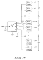
- Fig. 6 shows a printing system 30 having a print head controller 32 coupled to a print head 34 (such as a thermal ink-jet print head).
- a thermal ink-jet print head has an array of multiple nozzles for depositing drops of ink onto a recording media to produce printed images.
- the nozzle array can be arranged in a variety of configurations.
- Example nozzle arrangements include a single vertical column (i.e., an in-line print head), two side-by-side vertical columns (e.g., parallel or staggered), or a matrix configuration.
- Ink droplets are ejected from individual nozzles of print head 34 by localized heating.
- a small heating element is disposed at individual nozzles and an electrical current is passed through the element to heat it up. The heating element rapidly heats and vaporizes a tiny volume of ink. The vaporized ink is then ejected through the nozzle.
- print head 34 is considered to have a single in-line array of 48 nozzles n1-n48 as shown in Fig. 7.
- This example nozzle construction is used throughout this disclosure to facilitate an understanding of the numerous techniques for electronically compensating for pen misalignment; however, the invention may be employed for different print heads having varying numbers of nozzles and/or nozzle arrangements. It should be noted that this invention is particularly useful for print heads having a large array of nozzles, such as a vertical array of 100 or more nozzles, because the ⁇ -Z error resulting from mechanical pen misalignment is often more pronounced for longer arrays.
- print head controller 32 provides a data stream via bus 36 to print head 34.
- the data stream contains binary bits of "1"s and "0"s which are used to selectively fire the nozzles within the print head.
- the "1" bit causes the associated print head nozzle to deposit an ink drop whereas the "0" bit instructs the associated nozzle not to deposit an ink drop.
- Print head controller 32 also has a fire signal generator 38 which produces at least one fire signal 40 used to fire the array of nozzles according to the data bits at the respective individual nozzles.
- the fire signal is an energy pulse of sufficient magnitude and duration to heat and vaporize the ink, and thereby eject an ink drop from the nozzle. In this manner, the print head controller 32 effectively commands the print head 34 to fire individual nozzles and thereby controllably deposit the ink drops according to a desired pattern defined by the data stream.
- print head 34 would actually print images that are different from the desired pattern by a rotational ⁇ -Z error as shown, for example, in Fig. 2.
- the printing system of this invention is designed to include an electronic error correction means for reducing the ⁇ -Z error in the printed image.
- the error correction means (which can be resident in the print head controller, on the print head, and/or separate from both) causes print head 34 to fire two or more sets of nozzles at slightly different times during the same swath of the print head across the media.
- the linear array of nozzles n1-n48 can be segmented into multiple sets.
- the array can be segmented into two sets, with set 1 containing the upper half of the nozzles (i.e., n1-n24) and set 2 containing the lower half of the nozzles (i.e., n25-n48).
- the data stream supplied via bus 36 has "first data" for use in selectively firing corresponding nozzles n1-n24 in set 1 and "second data" for use in selectively firing corresponding nozzles n25-n48 in set 2.
- the array of nozzles can be segmented into three sets wherein the upper third nozzles (n1-n16) form set 1, the middle third nozzles (n17-n32) form set 2, and the lower third nozzles (n33-n48) form set 3.
- the data stream supplied via bus 36 has "first data” for use in selectively firing nozzles n1-n16 in set 1, "second data” for use in selectively firing nozzles n17-n32 in set 2, and "third data” for use in selectively firing nozzles n33-n48 in set 3. It is noted that in this three set example, the original ⁇ x displacement between segments (Fig. 2) is reduced by a factor of three to a displacement of ⁇ x/3.
- error correction means causes the print head to fire the upper nozzles (n1-n24 or set 1) at a different time than the lower nozzies (n25-n48 or set 2).
- the upper nozzles are fired after the lower nozzles; whereas for a right-to-left swath, the upper nozzles are fired before the lower nozzles. This causes the upper ink drops to be displaced or offset relative to the lower ink drops on the recording media.
- the result of depositing the ink drops in a displaced manner is to produce a printed image having one portion offset relative to another portion.
- the relative offset has the. visual effect of reducing the ⁇ -Z error shown in Fig. 4.
- the ⁇ -Z error correction means of this invention can be tailored depending upon the type and severity of the ⁇ -Z error.
- the ⁇ -Z error may induce a negatively sloped nearly vertical line of Fig. 2 which is rotated in a positive direction relative to the ideal vertical line.
- the ⁇ -Z error correction means is configured to cause a leftward shift of the lower image portion relative to the upper image portion as shown in Fig. 4.
- the ⁇ -Z error may induce a positively sloped nearly vertical line which is rotated in a negative ⁇ direction relative to the ideal vertical line.
- the ⁇ -Z error correction means is configured to cause a rightward shift of the lower image portion relative to the upper image portion.
- Figs. 8-21 show various different and unique embodiments of the error correction means according to this invention.
- Figs. 8-10 show a first embodiment wherein separate fire signals are used to fire sets of nozzles at different times to achieve the ⁇ -Z error correcting image offset.
- Fig. 8 shows a printing system 50 having a print head controller 52 coupled to a print head 54. Controller 52 provides data to print head 54 via bus 56.
- a signal generator 58 produces a first fire signal A and a second fire signal B at different times as shown, for example, in the timing diagram of Fig. 10.
- Signal generator 58 is illustrated as being part of print head controller 52, but can alternatively be configured separate from the controller.
- coupling circuitry 60 includes conductor 62 which connects the first fire signal A to a first set of nozzles (represented by nozzles n1 and n2) and conductor 64 which connects the second fire signal B to a second set of nozzles (represented by nozzles n47 and n48).
- the data DATA 0-DATA 47 are input to respective nozzles n1-n48.
- the time spaced fire signals A and B are therefore used to fire the two sets of nozzles at different times to produce the correcting offset in the printed image (Fig. 4).
- the error correction means comprises signal generator 58 and coupling circuitry 60.
- Figs. 11-13 show a second embodiment which delays the fire signal from reaching some nozzles so that the nozzles fire at different times to correct the ⁇ -Z error.
- Fig. 11 shows a printing system 70 having a print head controller 72 coupled to a print head 74 to provide data via bus 76.
- a signal generator 78 produces a fire signal 80 for firing the nozzles within the print head array.
- Fire signal 80 is input to a delay circuit 82 which is preferably provided on print head 74, but it can also be provided elsewhere, such as in print head controller 72.
- delay circuit 82 receives the fire signal F(t) and outputs a non-delayed fire signal A and two delayed fire signals B and C.
- Fire signal B is delayed by a time duration equal to one delay period or F(t-delay)
- fire signal C is delayed by a time duration equal to two delay periods or F(t-2delay).
- the delay period is the width of the firing pulse, although other delay periods may be used.
- Delay circuit 82 is preferably a programmable delay device which permits the delay periods to be set by the user or manufacturer to compensate for the varying degrees of pen misalignment.
- Example programmable delay devices include digital counters, RC networks, and digital delay lines.
- the printing system 70 also includes coupling circuitry 84 (Fig. 12) to connect the fire signals to sets of nozzles n1-n48.
- the nozzles are segmented into three sets.
- Coupling circuitry 84 has a conductor 85 to connect non-delayed signal A to the first set of nozzles (n1-n16), a conductor 86 to connect the one period delayed signal B to the second set of nozzles (n17-n32), and a conductor 87 to connect the two period delayed signal C to the third set of nozzles (n33-n48).
- the error correction means comprises delay circuitry 82 and coupling circuitry 84, and may also include signal generator 78.
- the time spaced fire signals A-C are used to fire the three sets of nozzles at different times to produce three offsetting segments within the same swath which are effective to reduce the ⁇ -Z error in the printed image.
- the delayed signals are shown as going to the lower nozzles, the delay circuit can be programmed to route the delayed signals to the upper nozzles as desired. The delay duration and routing are dependent upon the swath direction of the print head and the rotational direction and magnitude of the ⁇ -Z error.
- Figs. 14-16 show a third embodiment which dispenses the fire signal to various sets of nozzles so that the nozzles fire at different times to correct the mechanical ⁇ -Z error.
- Fig. 14 shows a printing system 90 having a print head controller 92 coupled to a print head 94 to provide data via bus 96.
- a signal generator 98 produces a fire signal 100 for firing the nozzles within the print head array.
- Fire signal 100 is input to a switching circuit 102 which is preferably provided on print head 94 (as shown), but can also be provided elsewhere.
- switching circuit 102 receives fire signal 100 and alternately distributes the fire signal to three sets of nozzles as signals A, B, and C. Between each fire pulse, the switch automatically steps to the next output so that signals A, B, and C are time spaced as illustrated in the timing diagram of Fig. 16. The frequency of the fire signal is increased in comparison to the typical fire pulse frequency in which a single pulse is used to fire the entire nozzle array simultaneously. Here, three fire pulses are used to fire the entire nozzle array.
- Example implementations of switching circuit 102 include a counter, a self-advancing switch, and a demultiplexor.
- Printing system 90 also includes coupling circuitry 104 (Fig. 15) having conductors 106-108 which connect fire signals A-C to respective sets of nozzles n1-n48.
- the time spaced fire signals A-C are used to fire three sets of nozzles at different times to produce the correcting offset in the printed image.
- the error correction means comprises switching circuitry 102 and may also include coupling circuitry 104 and signal generator 78.
- the three embodiments described above with respect to Figs. 8-16 provide distinctive approaches to distributing the fire signal to separate sets of nozzles.
- the coupling circuitry, the switching circuit, and the delay circuit all represent types of distribution means for applying the one or more fire signals to multiple sets of nozzles at different times in order to create the desired image offset.
- Figs. 17 and 18 show a fourth embodiment which employs logic circuitry to selectively pass the data to the nozzles as another technique for reducing the rotational ⁇ -Z error.
- Fig. 17 shows a printing system 110 having a print head controller 112 and print head 114.
- a signal generator 116 produces a fire signal 118 which is input to print head 114 for firing the nozzles within the print head array.
- Printing system 110 has logic circuitry 120 coupled between print head controller 112 and print head 114 on data bus 122 to intercept the data before it is input to the print head.
- Logic circuitry 120 is designed to selectively pass the data on bus 124 to various sets of nozzles at different times. The logic circuitry selectively passes the data in response to one or more enable signals provided over line(s) 126 from logic control circuit 128.
- Fig. 18 shows an example construction of logic circuitry 120 in more detail.
- logic circuitry 120 comprises multiple AND gates 130, where individual AND gates have one input coupled to receive the data from print head controller 112, a second input coupled to receive an enable signal from logic control circuit 128, and an output coupled to selectively supply data to print head 114.
- AND gates 130 pass the data from print head controller 112 through to print head 114 when the enable signal (e.g., an asserted HIGH) is input to the gates. If the data contains a "1" bit, the AND gate outputs a "1" bit; and if the data contains a "0" bit, the AND gate outputs a "0" bit. Conversely, when the enable signal is not applied to the AND gates 130 (e.g. an asserted LOW condition), the AND gates output bits (e.g. "0" bits) which do not fire the nozzles, regardless of the data applied to the other input of the AND gates.
- the enable signal e.g., an asserted HIGH
- logic control circuit 128 generates enable signals for those AND gates 130 associated with different sets of nozzles to fire different sets of nozzles according to the passed data stream. This has the effect of firing the nozzles at different times to produce the error reducing relative image offset. It should be noted that other logic configurations apart from AND gates can achieve the same function.
- the error correction means is embodied as logic circuitry 120 and logic control circuitry 128.
- a separate line 126 is connected to each AND gate 130 so that the control circuit could theoretically cause each data bit DATA 0-DATA 47 to be passed at slightly staggered times relative to the other bits. This affords maximum control for near perfect correction of the rotational ⁇ -Z error.
- less lines 126 are coupled to groups of AND gates to define the sets of nozzles. For example, one line could be connected to half of the AND gates 130 to control ink deposition from one set of nozzles and a second line could be connected to the other half of the AND gates 130 to control ink deposition from a second set of nozzles.
- Fig. 19 shows a printing system 140 according to a fifth embodiment of this invention which digitally manipulates the data stream to be input to the print head in a way that causes the nozzles to fire at slightly different times.
- Printing system 140 includes a print head controller 142 coupled - to print head 144 via data bus 146 and fire signal line 148.
- Printing system 140 also includes a data manipulation circuit 150 coupled between memory 152 and print head controller 142. Data manipulation circuit 150 manipulates the data output from memory 152 before the data is input into controller 142.
- a bit ordering circuit (not shown) can also be inserted between data manipulation circuit 150 and print head controller 142 to organize and order the bits within the data stream relative to the appropriate nozzle drivers in the firing circuit. Alternatively, the data manipulation circuit 150 or print head controller 142 can be configured to handle the bit ordering function.
- Data manipulation circuit 150 manipulates the data in such a manner that causes the print head to fire sets of nozzles at time-spaced intervals.
- circuit 150 manipulates the data according to a bit shifting translation illustrated in Fig. 20.
- Fig. 20 As an example, suppose that the data stream from memory 152 contains an entire column of "1" bits for simultaneously firing all 48 nozzles to draw a vertical line segment.
- the bits used to selectively fire corresponding nozzles n1-n24 represent the "first data” and the bits used to selectively fire corresponding nozzles n25-n48 represent the "second data".
- Data manipulation circuit 150 has a bit duplicating means for replicating the first and second data to form two columns 1A and 1B of the first and second data. Initially, the columns are identical. However, the manipulation circuit further includes a bit shifting means for replacing the first data in column 1A with "0" bits (which do not fire the nozzles) and leaving the first data in column 1B unchanged. The bit shifting means also replaces the second data in column 1B with "0" bits while leaving the second data in column 1A unchanged.
- the bit translation yields a modified data stream which is input into the print head firing control circuit.
- the data in column 1A is input first, causing the print head to fire lower nozzles n25-n48 and print the lower ink drops.
- the data in column 1B is input, causing the print head to fire the upper nozzles n1 -n24 and print the upper ink drops.
- the time delay between printing the data in column 1A and the data in column 1B produces the image offset shown in Fig. 4.
- the error correction means comprises the data manipulation circuit used to shift the data to achieve the desired image offset.
- bit duplicating means and a bit shifting means are to employ parallel registers which store and write the replicated and modified data to the print head controller during sequential write operations.
- Another example implementation is to send the same data bit twice to the print head controller (i.e., using the following write sequence --. load data, send data, send data).
- the data bits are channeled through logic circuitry, such as AND gates, which operatively passes the data in a manner similar to that described above with respect to Figs. 17 and 18. For example, the logic would selectively pass the second data in column 1A and the first data in column 1B while sending "0" bits as the first data in column 1A and the second data in column 1B.
- Fig. 21 shows a printing system 160 according to a sixth embodiment of this invention which is similar to the Fig. 19 embodiment, but includes means for manipulating the data before it is input to printer memory 152. More particularly, printing system 160 includes a data manipulator 162 provided upstream from printer memory 152. In the illustrated embodiment, data manipulator 162 resides at the host computer in the form of driver software or a special circuit. The data manipulator performs the same data shifting techniques described above with respect to Figs. 19 and 20, but the replicating and shifting takes place prior to sending the data to the printer memory. In this embodiment, the error correction means comprises the data manipulator provided up stream of the printer memory.
- printing systems 140 and 160 may use larger memories or more registers to accommodatc the increased data set.
- All of the error correction techniques in this invention induce an image offset wherein one or more portions of the image are offset relative to one or more other portions.
- the relative offset is essentially one dot unit which is the smallest addressable unit along the carriage axis.
- one dot unit can be 1/600th of an inch for a 600 dpi setting.
- the error correction means can be configured to cause the time-staggered firing of more than two sets of nozzles.
- the error correction means of this invention can be designed to independently control all nozzles. In the example 48 nozzle print head of Fig. 7, the array can be segmented into forty-eight sets of one nozzle each.
- the nozzle sets may have unequal numbers of nozzles and that the data groupings may contain unequal numbers of bits.
- the nozzle array can be subdivided into five sets with set 1 containing nine nozzles n1-n9, set 2 having ten nozzles n10-n19, set 3 having ten nozzles n20-n29, set 4 having ten nozzles n30-n39, and set 5 having nine nozzles n40-n48.
- the data stream is considered to contain five groups of data with two groups having one less bit than the other three groups.
- the error correction means causes the print head to print five line segments with unit relative offsets therebetween in a correcting rotation effective to visually mask the mechanical ⁇ -Z error.
- the original ⁇ x displacement between segments (Fig. 2) is reduced by a factor of five, or ⁇ x/5.
- the electronic error correction techniques of this invention provide a low cost solution to the rotational ⁇ -Z error caused by mechanical pen misalignment.
- the replaceable pens are tested during manufacturing to detect and measure the ⁇ -Z error. Once the error is determined, the printer can be programmed automatically, or by the user, to correct for the ⁇ -Z error according to the techniques of this invention.
Abstract
Description
- This invention relates to ink-jet printers, and more particularly, to an ink-jet printing system, error correction circuitry, and a method for electronic correction of pen misalignment in ink-jet printers.
- An ink-jet printer is a type of non-impact printer which forms characters and other images by controllably spraying drops of ink from a print head. The print head ejects liquid ink through multiple nozzles in the form of annular drops which travel across a small air gap and land on a recording media. The drops are very small as ink-jet printers commonly print within a range of 180 to 600 dots per inch (dpi). The ink drops dry shortly thereafter to form in combination the desired printed images.
- The print head is commonly ported back and forth over the media by a movable carriage. As shown in Fig. 1,
print head 10 is carried by a carriage (not shown) over recordingmedia 12 along an x-axis in the "carriage scan direction". The print head has one or more vertical arrays of multiple nozzles (e.g., 48 nozzles) which simultaneously apply one or more columns of drops as the print head is moved over the media. The nozzles are closely aligned according to the desired dot-to-dot pitch (e.g., nozzle separation is 1/300th of an inch for a 300 dpi resolution). In this manner, the print head can deposit multiple rows of dots in a single swath in the carriage scan direction. - Upon completion of a carriage scan, the
media 12 is advanced along the y-axis in the "media advance direction" by the number of rows that the printer is capable of printing in one swath. Printing can be unidirectional (which is common for printing graphics) or bidirectional (which is common for printing text). - Today, most ink-jet print heads are constructed in the form of removable and replaceable print head cartridges or pens. In general, these pens have inherent mechanical variances due to imprecise manufacturing tolerances. Each disposable pen therefore mechanically differs from the others. Due to these mechanical variances, each pen rests within the printer carriage in a slightly different manner. Additionally, the printer carriage has its own set of tolerances which introduce another set of mechanical variances. As a result, the print characteristics and output patterns are non-uniform among the pens.
- A primary problem associated with the replaceable pens concerns misalignment of the nozzle array due to mechanical rotation of the pen about the z-axis. In Fig. 1, the z-axis is shown at the origin of the x-axis and y-axis and extends outward from, and perpendicular to, the drawing. The degree of freedom defining rotation about the z-axis is commonly referred to as "ϑ". Thus, the rotational misalignment of the pen about the z-axis resulting from mechanical imperfections is generally referred to as the "ϑ-Z error".
- Fig. 2 illustrates the ϑ-Z error in more detail. Suppose that the print head is expected to print a vertical line. Under ideal conditions, a mechanically perfect print head would print the ideal vertical line (represented by the dashed vertical line). However, due to the ϑ-Z error, the mechanically imperfect print head actually prints the slanted line which has an angular error of ϑ relative to the ideal line. The negative slope in the actual line is exaggerated in the figure to illustrate the ϑ-Z error. The ϑ-Z error yields a Δx displacement at the extreme end of the nozzle array. As can be appreciated, this Δx displacement increases in relation to the length of the nozzle array in the print head.
- The ϑ-Z error manifests itself most prominently when the printer is operating in the graphics mode, as opposed to the text mode. In graphics mode, the printed image continues from one swath to the next. An example graphics application is printing a vertical line from top-to-bottom of a page, wherein the vertical segments formed in sequential swaths combine to form a continuous vertical line. In contrast, for text mode, the entire image (such as letters and numbers) is printed within the same swath within the constraints of common font sizes.
- Fig. 3 shows the effect of the ϑ-Z error in the graphics application of drawing a continuous vertical line. The print
head prints segment 14 during the first swath, thensegment 15 on the second swath, and finallysegment 16 during the third swath. Unfortunately, due to the ϑ-Z error of the mechanically misaligned pen, a set of discontinuous, jagged segments 14-16 is actually printed instead of the desired continuous vertical line. Each jagged discontinuity contains the Δx displacement caused by the ϑ-Z error. - Imposing tighter manufacturing tolerances to reduce the mechanical variances in replaceable pens would help remove the ϑ-Z error. Unfortunately, such tolerances significantly increase the production cost of the pens. Accordingly, imposing tighter mechanical tolerances is not a suitable low cost solution to the ϑ-Z misalignment problem.
- This invention provides a low cost solution for reducing the perceived ϑ-Z error in an ink-jet print head using electronic techniques that effectively reduce the Δx displacement.
- According to one aspect of this invention, an ink-jet printing system includes a print head having an array of multiple nozzles for depositing drops of ink onto a recording media during a swath to produce printed images. A print head controller is coupled to the print head to fire individual nozzles and thereby controllably deposit the ink drops according to a desired pattern. If left uncorrected, however, the printed images produced by the print head would be different from the desired pattern by a rotational ϑ-Z error. The printing system therefore also includes an error correction means for reducing the ϑ-Z error in the printed image. The error correction means causes the print head to fire during the same swath (1) a first set of nozzles in the print head array to deposit first ink drops and (2) a second set of nozzles in the print head array to deposit second ink drops which are offset relative to the first ink drops on the recording media. The relative offset between the first and second ink drops are effective to reduce the ϑ-Z error in the printed image.
- This invention also relates to numerous distinct embodiments of the error correction means. In one embodiment, separate fire signals are used to fire sets of nozzles at different times to achieve the ϑ-Z error correcting image offset. In another embodiment, the fire signal is delayed from reaching some nozzles so that the nozzles fire at different times to correct the ϑ-Z error. In still another embodiment, the fire signal is selectively dispensed to various sets of nozzles to fire them at different times and thereby correct the ϑ-Z error. In yet another embodiment, logic circuitry is employed to selectively pass the data to the nozzles in a manner which reduces the rotational ϑ-Z error. In other embodiments, the data stream to be input to the print head is digitally manipulated to cause the nozzles within the print head to fire at slightly different times.
- This invention also relates to a method for reducing a ϑ-Z error in an image printed by an ink-jet printer. The method comprises segmenting the array of nozzles in the print head into at least first and second sets of nozzles. Then, during the same swath, (1) a first portion of the image is printed using the first set of nozzles in the print head, and (2) a second portion of the image is printed using the second set of nozzles in the print head, whereby the second portion of the image is offset relative to the first portion in a direction effective to reduce the ϑ-Z error.
- Preferred embodiments of the invention are described below with reference to the following accompanying drawings depicting examples embodying the best mode for practicing the invention.
- Fig. 1 illustrates the relative movement of a print head and recording media in a printer.
- Fig. 2 illustrates a rotational ϑ-Z error caused by mechanical misalignment in a print head.
- Fig. 3 illustrates in an exaggerated manner a discontinuous vertical line formed by three consecutive swaths, whereby the discontinuity is caused by the rotational ϑ-Z error of Fig. 2.
- Fig. 4 illustrates a vertical line printed according to techniques of this invention wherein during a single swath, the lower portion of the image is offset from the upper portion in a direction effective to reduce the ϑ-Z error.
- Fig. 5 illustrates in an exaggerated manner a nearly vertical line formed by three consecutive swaths wherein each swath has the correcting offset shown in Fig. 4.
- Fig. 6 is a block diagram of a printing system according to this invention having a print head controller and print head.
- Fig. 7 illustrates segmentation of print head ink-jet nozzles into multiple sets according to this invention.
- Fig. 8 is a block diagram of an ink-jet printing system according to a first embodiment of this invention.
- Fig. 9 is a schematic of the nozzle circuitry employed in the first embodiment of Fig. 8.
- Fig. 10 is a timing diagram of the signals shown in the Fig. 9 circuitry.
- Fig. 11 is a block diagram of an ink-jet printing system according to a second embodiment of this invention having delay circuitry provided on the print head.
- Fig. 12 is a schematic of the delay and nozzle circuitry employed in the second embodiment of Fig. 11.
- Fig. 13 is a timing diagram of the signals shown in the Fig. 12 circuitry.
- Fig. 14 is a block diagram of an ink-jet printing system according to a third embodiment of this invention having switching circuitry provided on the print head.
- Fig. 15 is a schematic of the switching and nozzle circuitry employed in the third embodiment of Fig. 14.
- Fig. 16 is a timing diagram of the signals shown in the Fig. 15 circuitry.
- Fig. 17 is a block diagram of an ink-jet printing system according to a fourth embodiment of this invention having correcting logic circuitry.
- Fig. 18 is a schematic of an example logic circuitry used in the Fig. 17 embodiment.
- Fig. 19 is a block diagram of an ink-jet printing system according to a fifth embodiment of this invention having a data manipulation circuit.
- Fig. 20 illustrates a data shifting technique used in the fifth and sixth embodiments of Figs. 19 and 21.
- Fig. 21 is a block diagram of an ink-jet printing system according to a sixth embodiment of this invention having a data manipulator provided upstream of the printer memory.
- This invention is intended for use in an ink-jet printer. A typical ink-jet printer includes a platen, a shuttle assembly, an ink-jet print head, and a control system. The platen is preferably stationary and supports a recording media during printing. A media feed mechanism, such as friction rollers or a tractor feed system, is used to drive the media through the printer. The shuttle assembly includes a carriage slidably mounted on a fixed, elongated rod to move bidirectionally across the platen. The print head is mounted to the carriage to print images on the recording media as the carriage moves. The shuttle assembly also includes a drive subassembly (such as a stepper or DC motor, and a belt and pulley linkage) that mechanically maneuvers the drive carriage back and forth along the rod.
- As used herein, the terms "ink-jet printer" and "ink-jet print head" refer generally to non-impact printers having print heads which controllably eject a substance onto a recording media. The terms are intended to include piezoelectric-type non-impact printers having print heads which deposit ink drops using piezoelectric actuation, low thermal printers having print heads which eject ink drops through localized heating at the nozzle, and hot melt-type printers which pre-melt a substance (such as wax) prior to ejecting it onto the recording media. The term "ink", as used herein, is intended to cover any substance that can be deposited from the ink-jet print head. For purposes of discussion and to provide a comprehensive description of the invention, the invention is discussed in the context of a low thermal ink-jet printer.
- According to this invention, the rotational ϑ-Z error caused by mechanical misalignment in the print head is reduced through electronic techniques. The invention does not physically correct the ϑ-Z error in the misaligned pen by structurally realigning the pen, but instead reduces the Δx displacement via electronic correction to visually mask the ϑ-Z error. The electronic correction purposely causes a slight alteration in the printed image so that one portion of the image is offset relative to another portion of the image. The relative offset has the visual effect of reducing the ϑ-Z error. Said a different way, this invention intentionally skews a printed image in a direction effective to help cancel the rotational ϑ-Z error. This is shown in Figs. 4 and 5.
- In Fig. 4, the lower segment of the printed image is offset leftward relative to the upper segment of the printed image. The two segments are printed by two sets of nozzles within the print head during the same swath. The offsetting image effectively reduces the Δx displacement (Fig. 2) by approximately half, or Δx/2.
- Fig. 5 shows how the image offset diminishes the perceived ϑ-Z error in the graphics application of drawing a continuous vertical line. The print head prints two
segments segments segments segments 18a-20b is visually imperceivable. - Fig. 6 shows a
printing system 30 having aprint head controller 32 coupled to a print head 34 (such as a thermal ink-jet print head). A thermal ink-jet print head has an array of multiple nozzles for depositing drops of ink onto a recording media to produce printed images. The nozzle array can be arranged in a variety of configurations. Example nozzle arrangements include a single vertical column (i.e., an in-line print head), two side-by-side vertical columns (e.g., parallel or staggered), or a matrix configuration. Ink droplets are ejected from individual nozzles ofprint head 34 by localized heating. A small heating element is disposed at individual nozzles and an electrical current is passed through the element to heat it up. The heating element rapidly heats and vaporizes a tiny volume of ink. The vaporized ink is then ejected through the nozzle. - U.S. Patent No. 4,910,528 describes one possible print head construction in more detail. This U.S. Patent No. 4,910,528 is incorporated herein by reference.
- For purposes of continuing discussion,
print head 34 is considered to have a single in-line array of 48 nozzles n1-n48 as shown in Fig. 7. This example nozzle construction is used throughout this disclosure to facilitate an understanding of the numerous techniques for electronically compensating for pen misalignment; however, the invention may be employed for different print heads having varying numbers of nozzles and/or nozzle arrangements. It should be noted that this invention is particularly useful for print heads having a large array of nozzles, such as a vertical array of 100 or more nozzles, because the ϑ-Z error resulting from mechanical pen misalignment is often more pronounced for longer arrays. - With reference again to Fig. 6,
print head controller 32 provides a data stream viabus 36 to printhead 34. The data stream contains binary bits of "1"s and "0"s which are used to selectively fire the nozzles within the print head. As an example, the "1" bit causes the associated print head nozzle to deposit an ink drop whereas the "0" bit instructs the associated nozzle not to deposit an ink drop.Print head controller 32 also has afire signal generator 38 which produces at least onefire signal 40 used to fire the array of nozzles according to the data bits at the respective individual nozzles. The fire signal is an energy pulse of sufficient magnitude and duration to heat and vaporize the ink, and thereby eject an ink drop from the nozzle. In this manner, theprint head controller 32 effectively commands theprint head 34 to fire individual nozzles and thereby controllably deposit the ink drops according to a desired pattern defined by the data stream. - It is noted that due to mechanical misalignment, and if left uncorrected,
print head 34 would actually print images that are different from the desired pattern by a rotational ϑ-Z error as shown, for example, in Fig. 2. - The printing system of this invention is designed to include an electronic error correction means for reducing the ϑ-Z error in the printed image. The error correction means (which can be resident in the print head controller, on the print head, and/or separate from both) causes
print head 34 to fire two or more sets of nozzles at slightly different times during the same swath of the print head across the media. - As shown in Fig. 7, the linear array of nozzles n1-n48 can be segmented into multiple sets. For example, the array can be segmented into two sets, with
set 1 containing the upper half of the nozzles (i.e., n1-n24) and set 2 containing the lower half of the nozzles (i.e., n25-n48). In this example, the data stream supplied viabus 36 has "first data" for use in selectively firing corresponding nozzles n1-n24 inset 1 and "second data" for use in selectively firing corresponding nozzles n25-n48 inset 2. - As another example, the array of nozzles can be segmented into three sets wherein the upper third nozzles (n1-n16) form set 1, the middle third nozzles (n17-n32) form set 2, and the lower third nozzles (n33-n48)
form set 3. In this example, the data stream supplied viabus 36 has "first data" for use in selectively firing nozzles n1-n16 inset 1, "second data" for use in selectively firing nozzles n17-n32 inset 2, and "third data" for use in selectively firing nozzles n33-n48 inset 3. It is noted that in this three set example, the original Δx displacement between segments (Fig. 2) is reduced by a factor of three to a displacement of Δx/3. - To achieve the correcting offset illustrated in Fig. 4, error correction means causes the print head to fire the upper nozzles (n1-n24 or set 1) at a different time than the lower nozzies (n25-n48 or set 2). For a left-to-right swath in the carriage scan direction, the upper nozzles are fired after the lower nozzles; whereas for a right-to-left swath, the upper nozzles are fired before the lower nozzles. This causes the upper ink drops to be displaced or offset relative to the lower ink drops on the recording media.
- The result of depositing the ink drops in a displaced manner is to produce a printed image having one portion offset relative to another portion. The relative offset has the. visual effect of reducing the ϑ-Z error shown in Fig. 4.
- The ϑ-Z error correction means of this invention can be tailored depending upon the type and severity of the ϑ-Z error. For example, the ϑ-Z error may induce a negatively sloped nearly vertical line of Fig. 2 which is rotated in a positive direction relative to the ideal vertical line. To diminish this error, the ϑ-Z error correction means is configured to cause a leftward shift of the lower image portion relative to the upper image portion as shown in Fig. 4. On the other hand, the ϑ-Z error may induce a positively sloped nearly vertical line which is rotated in a negative ϑ direction relative to the ideal vertical line. To diminish this error, the ϑ-Z error correction means is configured to cause a rightward shift of the lower image portion relative to the upper image portion.
- Figs. 8-21 show various different and unique embodiments of the error correction means according to this invention.
- Figs. 8-10 show a first embodiment wherein separate fire signals are used to fire sets of nozzles at different times to achieve the ϑ-Z error correcting image offset. Fig. 8 shows a
printing system 50 having aprint head controller 52 coupled to aprint head 54.Controller 52 provides data to printhead 54 viabus 56. Asignal generator 58 produces a first fire signal A and a second fire signal B at different times as shown, for example, in the timing diagram of Fig. 10.Signal generator 58 is illustrated as being part ofprint head controller 52, but can alternatively be configured separate from the controller. - In Fig. 9, the two fire signals A and B are connected to two different sets of nozzles via
coupling circuitry 60. More specifically,coupling circuitry 60 includesconductor 62 which connects the first fire signal A to a first set of nozzles (represented by nozzles n1 and n2) andconductor 64 which connects the second fire signal B to a second set of nozzles (represented by nozzles n47 and n48). The data DATA 0-DATA 47 are input to respective nozzles n1-n48. The nozzles are designed to selectively deposit ink drops according to the data at the respective data inputs (i.e., a "1" bit = ink drop; "0" bit = no ink drop) upon receipt of the fire signal at the respective enable inputs. The time spaced fire signals A and B are therefore used to fire the two sets of nozzles at different times to produce the correcting offset in the printed image (Fig. 4). In this embodiment, the error correction means comprisessignal generator 58 andcoupling circuitry 60. - Figs. 11-13 show a second embodiment which delays the fire signal from reaching some nozzles so that the nozzles fire at different times to correct the ϑ-Z error. Fig. 11 shows a
printing system 70 having aprint head controller 72 coupled to aprint head 74 to provide data viabus 76. Asignal generator 78 produces afire signal 80 for firing the nozzles within the print head array.Fire signal 80 is input to adelay circuit 82 which is preferably provided onprint head 74, but it can also be provided elsewhere, such as inprint head controller 72. - As shown in Figs. 12 and 13,
delay circuit 82 receives the fire signal F(t) and outputs a non-delayed fire signal A and two delayed fire signals B and C. Fire signal B is delayed by a time duration equal to one delay period or F(t-delay), whereas fire signal C is delayed by a time duration equal to two delay periods or F(t-2delay). As shown in Fig. 13, the delay period is the width of the firing pulse, although other delay periods may be used.Delay circuit 82 is preferably a programmable delay device which permits the delay periods to be set by the user or manufacturer to compensate for the varying degrees of pen misalignment. Example programmable delay devices include digital counters, RC networks, and digital delay lines. - The
printing system 70 also includes coupling circuitry 84 (Fig. 12) to connect the fire signals to sets of nozzles n1-n48. In this example, the nozzles are segmented into three sets. Couplingcircuitry 84 has aconductor 85 to connect non-delayed signal A to the first set of nozzles (n1-n16), aconductor 86 to connect the one period delayed signal B to the second set of nozzles (n17-n32), and aconductor 87 to connect the two period delayed signal C to the third set of nozzles (n33-n48). In this embodiment, the error correction means comprisesdelay circuitry 82 andcoupling circuitry 84, and may also includesignal generator 78. - The time spaced fire signals A-C are used to fire the three sets of nozzles at different times to produce three offsetting segments within the same swath which are effective to reduce the ϑ-Z error in the printed image. Although the delayed signals are shown as going to the lower nozzles, the delay circuit can be programmed to route the delayed signals to the upper nozzles as desired. The delay duration and routing are dependent upon the swath direction of the print head and the rotational direction and magnitude of the ϑ-Z error.
- Figs. 14-16 show a third embodiment which dispenses the fire signal to various sets of nozzles so that the nozzles fire at different times to correct the mechanical ϑ-Z error. Fig. 14 shows a
printing system 90 having aprint head controller 92 coupled to aprint head 94 to provide data viabus 96. Asignal generator 98 produces afire signal 100 for firing the nozzles within the print head array.Fire signal 100 is input to aswitching circuit 102 which is preferably provided on print head 94 (as shown), but can also be provided elsewhere. - As shown in Figs. 15 and 16, switching
circuit 102 receivesfire signal 100 and alternately distributes the fire signal to three sets of nozzles as signals A, B, and C. Between each fire pulse, the switch automatically steps to the next output so that signals A, B, and C are time spaced as illustrated in the timing diagram of Fig. 16. The frequency of the fire signal is increased in comparison to the typical fire pulse frequency in which a single pulse is used to fire the entire nozzle array simultaneously. Here, three fire pulses are used to fire the entire nozzle array. Example implementations of switchingcircuit 102 include a counter, a self-advancing switch, and a demultiplexor. -
Printing system 90 also includes coupling circuitry 104 (Fig. 15) having conductors 106-108 which connect fire signals A-C to respective sets of nozzles n1-n48. The time spaced fire signals A-C are used to fire three sets of nozzles at different times to produce the correcting offset in the printed image. In this embodiment, the error correction means comprises switchingcircuitry 102 and may also includecoupling circuitry 104 andsignal generator 78. - The three embodiments described above with respect to Figs. 8-16 provide distinctive approaches to distributing the fire signal to separate sets of nozzles. The coupling circuitry, the switching circuit, and the delay circuit all represent types of distribution means for applying the one or more fire signals to multiple sets of nozzles at different times in order to create the desired image offset.
- Figs. 17 and 18 show a fourth embodiment which employs logic circuitry to selectively pass the data to the nozzles as another technique for reducing the rotational ϑ-Z error. Fig. 17 shows a
printing system 110 having aprint head controller 112 andprint head 114. Asignal generator 116 produces afire signal 118 which is input to printhead 114 for firing the nozzles within the print head array. -
Printing system 110 haslogic circuitry 120 coupled betweenprint head controller 112 andprint head 114 ondata bus 122 to intercept the data before it is input to the print head.Logic circuitry 120 is designed to selectively pass the data onbus 124 to various sets of nozzles at different times. The logic circuitry selectively passes the data in response to one or more enable signals provided over line(s) 126 fromlogic control circuit 128. - Fig. 18 shows an example construction of
logic circuitry 120 in more detail. Here,logic circuitry 120 comprises multiple ANDgates 130, where individual AND gates have one input coupled to receive the data fromprint head controller 112, a second input coupled to receive an enable signal fromlogic control circuit 128, and an output coupled to selectively supply data to printhead 114. - According to this logic arrangement, AND
gates 130 pass the data fromprint head controller 112 through to printhead 114 when the enable signal (e.g., an asserted HIGH) is input to the gates. If the data contains a "1" bit, the AND gate outputs a "1" bit; and if the data contains a "0" bit, the AND gate outputs a "0" bit. Conversely, when the enable signal is not applied to the AND gates 130 (e.g. an asserted LOW condition), the AND gates output bits (e.g. "0" bits) which do not fire the nozzles, regardless of the data applied to the other input of the AND gates. - In this manner,
logic control circuit 128 generates enable signals for those ANDgates 130 associated with different sets of nozzles to fire different sets of nozzles according to the passed data stream. This has the effect of firing the nozzles at different times to produce the error reducing relative image offset. It should be noted that other logic configurations apart from AND gates can achieve the same function. In this embodiment, the error correction means is embodied aslogic circuitry 120 andlogic control circuitry 128. - In Fig. 18, a
separate line 126 is connected to each ANDgate 130 so that the control circuit could theoretically cause each data bit DATA 0-DATA 47 to be passed at slightly staggered times relative to the other bits. This affords maximum control for near perfect correction of the rotational ϑ-Z error. In less complex constructions,less lines 126 are coupled to groups of AND gates to define the sets of nozzles. For example, one line could be connected to half of the ANDgates 130 to control ink deposition from one set of nozzles and a second line could be connected to the other half of the ANDgates 130 to control ink deposition from a second set of nozzles. - Fig. 19 shows a
printing system 140 according to a fifth embodiment of this invention which digitally manipulates the data stream to be input to the print head in a way that causes the nozzles to fire at slightly different times.Printing system 140 includes aprint head controller 142 coupled - to printhead 144 viadata bus 146 andfire signal line 148.Printing system 140 also includes adata manipulation circuit 150 coupled betweenmemory 152 andprint head controller 142.Data manipulation circuit 150 manipulates the data output frommemory 152 before the data is input intocontroller 142. A bit ordering circuit (not shown) can also be inserted betweendata manipulation circuit 150 andprint head controller 142 to organize and order the bits within the data stream relative to the appropriate nozzle drivers in the firing circuit. Alternatively, thedata manipulation circuit 150 orprint head controller 142 can be configured to handle the bit ordering function. -
Data manipulation circuit 150 manipulates the data in such a manner that causes the print head to fire sets of nozzles at time-spaced intervals. Preferably,circuit 150 manipulates the data according to a bit shifting translation illustrated in Fig. 20. As an example, suppose that the data stream frommemory 152 contains an entire column of "1" bits for simultaneously firing all 48 nozzles to draw a vertical line segment. Suppose also that the bits used to selectively fire corresponding nozzles n1-n24 represent the "first data" and the bits used to selectively fire corresponding nozzles n25-n48 represent the "second data". -
Data manipulation circuit 150 has a bit duplicating means for replicating the first and second data to form twocolumns column 1A with "0" bits (which do not fire the nozzles) and leaving the first data incolumn 1B unchanged. The bit shifting means also replaces the second data incolumn 1B with "0" bits while leaving the second data incolumn 1A unchanged. - The bit translation yields a modified data stream which is input into the print head firing control circuit. For a left-to-right swath, the data in
column 1A is input first, causing the print head to fire lower nozzles n25-n48 and print the lower ink drops. Then, the data incolumn 1B is input, causing the print head to fire the upper nozzles n1 -n24 and print the upper ink drops. The time delay between printing the data incolumn 1A and the data incolumn 1B produces the image offset shown in Fig. 4. In this embodiment, the error correction means comprises the data manipulation circuit used to shift the data to achieve the desired image offset. - One example implementation of a bit duplicating means and a bit shifting means is to employ parallel registers which store and write the replicated and modified data to the print head controller during sequential write operations. Another example implementation is to send the same data bit twice to the print head controller (i.e., using the following write sequence --. load data, send data, send data). The data bits are channeled through logic circuitry, such as AND gates, which operatively passes the data in a manner similar to that described above with respect to Figs. 17 and 18. For example, the logic would selectively pass the second data in
column 1A and the first data incolumn 1B while sending "0" bits as the first data incolumn 1A and the second data incolumn 1B. - Fig. 21 shows a
printing system 160 according to a sixth embodiment of this invention which is similar to the Fig. 19 embodiment, but includes means for manipulating the data before it is input toprinter memory 152. More particularly,printing system 160 includes adata manipulator 162 provided upstream fromprinter memory 152. In the illustrated embodiment,data manipulator 162 resides at the host computer in the form of driver software or a special circuit. The data manipulator performs the same data shifting techniques described above with respect to Figs. 19 and 20, but the replicating and shifting takes place prior to sending the data to the printer memory. In this embodiment, the error correction means comprises the data manipulator provided up stream of the printer memory. - It is noted that the "0" filling technique of Figs. 19-21 approximately doubles the amount of data sent to the print head. Accordingly,
printing systems - All of the error correction techniques in this invention induce an image offset wherein one or more portions of the image are offset relative to one or more other portions. The relative offset is essentially one dot unit which is the smallest addressable unit along the carriage axis. As an example, one dot unit can be 1/600th of an inch for a 600 dpi setting.
- As is explained with respect to certain embodiments above, it should be emphasized that the error correction means can be configured to cause the time-staggered firing of more than two sets of nozzles. Taken to the theoretical limit, the error correction means of this invention can be designed to independently control all nozzles. In the example 48 nozzle print head of Fig. 7, the array can be segmented into forty-eight sets of one nozzle each.
- It should also be noted that the nozzle sets may have unequal numbers of nozzles and that the data groupings may contain unequal numbers of bits. As shown in Fig. 7, the nozzle array can be subdivided into five sets with
set 1 containing nine nozzles n1-n9, set 2 having ten nozzles n10-n19, set 3 having ten nozzles n20-n29, set 4 having ten nozzles n30-n39, and set 5 having nine nozzles n40-n48. In this case, the data stream is considered to contain five groups of data with two groups having one less bit than the other three groups. - For five sets, the error correction means causes the print head to print five line segments with unit relative offsets therebetween in a correcting rotation effective to visually mask the mechanical ϑ-Z error. The original Δx displacement between segments (Fig. 2) is reduced by a factor of five, or Δx/5.
- The electronic error correction techniques of this invention provide a low cost solution to the rotational ϑ-Z error caused by mechanical pen misalignment. In practice, the replaceable pens are tested during manufacturing to detect and measure the ϑ-Z error. Once the error is determined, the printer can be programmed automatically, or by the user, to correct for the ϑ-Z error according to the techniques of this invention.
- In compliance with the statute, the invention has been described in language more or less specific as to structural or methodical features. It is to be understood, however, that the invention is not limited to the specific features shown and described, since the means and methods herein disclosed comprise preferred forms of putting the invention into effect. The invention is, therefore, claimed in any of its forms or modifications within the proper scope of the appended claims appropriately interpreted in accordance with the doctrine of equivalents.
Claims (10)
- An ink-jet printing system comprising:
a print head (34) having an array of multiple nozzles (n1-n48) for depositing drops of ink onto a recording media during a swath to produce printed images;
a print head controller (32) for commanding the print head (34) to fire individual nozzles to controllably deposit the ink drops according to a desired pattern, the desired pattern being defined by a stream of data;
the printed images produced by the print head being different from the desired pattern by a rotational ϑ-Z error if the ink-jet printing system is left uncorrected; and
error correction means for reducing the ϑ-Z error in the printed image by causing the print head to fire during the same swath (a) a first set of nozzles in the print head array to deposit first ink drops and (b) a second set of nozzles in the print head array to deposit second ink drops which are offset relative to the first ink drops on the recording media, the relative offset of the first and second ink drops being effective to reduce the ϑ-Z error in the printed image. - An ink-jet printing system according to claim 1 wherein the error correction means generates time spaced first and second fire signals for firing the first and second sets of nozzles, respectively, at different times to produce the relative offset of the first and second ink drops on the recording media.
- An ink-jet printing system according to claim 1 wherein the error correction means comprises:
a fire signal generator (58) to produce first and second fire signals at different times; and
coupling circuitry (60) to connect the first fire signal to the first set of nozzles in the print head array and to connect the second fire signal to the second set of nozzles in the print head array, the first and second fire signals causing the first and second sets of nozzles to fire at different times to produce the relative offset of the first and second ink drops on the recording media. - An ink-jet printing system according to claim 1 wherein the print head controller has a fire signal generator (78) to create a fire signal for firing the nozzles (n1-n48) within the print head array; and
the error correction means comprises:
a delay circuit (82) coupled to the fire signal generator (78) to delay the fire signal by a time duration and thereby produce a delayed fire signal; and
coupling circuitry (84) to connect the fire signal to the first set of nozzles in the print head array and to connect the delayed fire signal to the second set of nozzles in the print head array, the non-delayed and delayed fire signals causing the first and second sets of nozzles to fire at different times to produce the relative offset of the first and second ink drops on the recording media. - An ink-jet printing system according to claim 1 wherein the print head controller (92) has a fire signal generator (98) to create a fire signal for firing the nozzles (n1-n48) within the print head array; and
the error correction means comprises:
a switching circuit (102) coupled to the fire signal generator (98) to alternately distribute the fire signal to the first set of nozzles at a first time and to the second set of nozzles at a second time different than the first time, the time distributed fire signals output from the switching circuit (102) causing the first and second sets of nozzles to fire at different times to produce the relative offset of the first and second ink drops on the recording media. - An ink-jet printing system according to claim 1 wherein the error correction means comprises:
logic circuitry (120) coupled between the print head controller (112) and the print head (114), the logic circuitry (120) receiving the data stream and selectively passing the data to the first set of nozzles in the print head at a different time than to the second set of nozzles, the logic circuitry (120) selectively passing the data to the first and second sets of nozzles in response to at least one enable signal; and
a logic control circuit (128) coupled to the logic circuitry (120) to generate the at least one enable signal. - An ink-jet printing system according to claim 1 further comprising:
a memory (152) for storing and outputting the stream of data, the data including first data for firing nozzles within the first set of nozzles and second data for firing nozzles within the second set of nozzles; and
the error correction means being coupled to the memory (152) and manipulating the data output from the memory before the data is input into the print head (144), the error correction means shifting one of the first and second data relative to the other so that the print head fires the first set of nozzles at a first time and the second set of nozzles at a second time to produce the relative offset of the first and second ink drops on the recording medium. - An ink-jet printing system according to claim 1 further comprising:
a memory (162) for receiving, storing and outputting the stream of data, the data including first data for firing nozzles within the first set of nozzles and second data for firing nozzles within the second set of nozzles; and
the error correction means being coupled to the memory (162) and manipulating the data before the data is input to the memory, the error correction means shifting one of the first and second data relative to the other so that the print head fires the first set of nozzles at a first time and the second set of nozzles at a second time to produce the relative offset of the first and second ink drops on the recording medium. - An ink-jet printing system according to claim 1 wherein:
the first set of nozzles comprises an upper portion of the print head nozzles and the second set of nozzles comprises a lower portion of the print head nozzles; and
the error correction means is configured to (a) cause a rightward offset of the second ink drops deposited by the lower portion of nozzles relative to the first ink drops deposited by the upper portion of nozzles to reduce a ϑ-Z error in one rotational direction, and (b) cause a leftward offset of the second ink drops deposited by the lower portion of nozzles relative to the first ink drops deposited by the upper portion of nozzles to reduce a ϑ-Z error in an opposite rotational direction. - An ink-jet printing system according to claim 1 wherein the error correction means is configured to cause the print head to fire three or more sets of nozzles in the print head array to yield multiple groups of relatively offset ink drops on the recording media which are effective to reduce the ϑ-Z error in the printed image.
Applications Claiming Priority (2)
| Application Number | Priority Date | Filing Date | Title |
|---|---|---|---|
| US22134294A | 1994-03-31 | 1994-03-31 | |
| US221342 | 1994-03-31 |
Publications (2)
| Publication Number | Publication Date |
|---|---|
| EP0674993A2 true EP0674993A2 (en) | 1995-10-04 |
| EP0674993A3 EP0674993A3 (en) | 1997-06-25 |
Family
ID=22827415
Family Applications (1)
| Application Number | Title | Priority Date | Filing Date |
|---|---|---|---|
| EP95302069A Withdrawn EP0674993A3 (en) | 1994-03-31 | 1995-03-28 | System, control circuit and method for electronic correction of pen misalignment in ink jet printers. |
Country Status (2)
| Country | Link |
|---|---|
| EP (1) | EP0674993A3 (en) |
| JP (1) | JPH07309007A (en) |
Cited By (57)
| Publication number | Priority date | Publication date | Assignee | Title |
|---|---|---|---|---|
| EP0791472A2 (en) * | 1996-02-22 | 1997-08-27 | Hewlett-Packard Company | Ink jet printing |
| DE19755873A1 (en) * | 1997-12-04 | 1999-06-10 | Francotyp Postalia Gmbh | Arrangement for tolerance compensation in an ink print head |
| DE19755874C1 (en) * | 1997-12-04 | 1999-07-15 | Francotyp Postalia Gmbh | Method for tolerance compensation in an ink print head composed of several modules according to the non-interlaced principle |
| EP0938973A3 (en) * | 1998-02-25 | 2000-03-22 | Tektronix, Inc. | Apparatus and method for automatically aligning print heads |
| EP1048472A1 (en) * | 1998-11-20 | 2000-11-02 | Seiko Epson Corporation | Dot forming timing-adjustable printer |
| EP1057647A2 (en) * | 1999-06-02 | 2000-12-06 | Hewlett-Packard Company | Ink jet printer |
| EP1100682A2 (en) * | 1998-07-29 | 2001-05-23 | Lexmark International, Inc. | Method and system for compensating for skew in an ink jet printer |
| EP1359013A1 (en) * | 2002-04-29 | 2003-11-05 | Hewlett-Packard Company | Fire pulses in a fluid ejection device |
| US6659581B2 (en) | 2001-01-05 | 2003-12-09 | Hewlett-Packard Development Company, L.P. | Integrated programmable fire pulse generator for inkjet printhead assembly |
| EP1386749A1 (en) * | 2002-08-02 | 2004-02-04 | Hewlett-Packard Development Company, L.P. | Misalignment reduction of staggered fluid ejector assemblies |
| EP1424200A1 (en) * | 2002-11-26 | 2004-06-02 | Toshiba Tec Kabushiki Kaisha | Ink-jet recording apparatus |
| WO2005058602A2 (en) | 2003-12-15 | 2005-06-30 | Lexmark International, Inc | Composite printhead fire signals |
| WO2005120835A1 (en) * | 2004-05-27 | 2005-12-22 | Silverbrook Research Pty Ltd | Method for at least partially compensating for errors in ink dot placement due to erroneous rotational displacement |
| US7029084B2 (en) | 2001-01-05 | 2006-04-18 | Hewlett-Packard Development Company, L.P. | Integrated programmable fire pulse generator for inkjet printhead assembly |
| US7093989B2 (en) | 2004-05-27 | 2006-08-22 | Silverbrook Research Pty Ltd | Printer comprising two uneven printhead modules and at least two printer controllers, one which spends print data to the other |
| EP1741560A2 (en) | 2005-07-08 | 2007-01-10 | Canon Kabushiki Kaisha | Ink jet printing apparatus and ink jet printing method |
| US7188928B2 (en) | 2004-05-27 | 2007-03-13 | Silverbrook Research Pty Ltd | Printer comprising two uneven printhead modules and at least two printer controllers, one of which sends print data to both of the printhead modules |
| US7243193B2 (en) | 2004-05-27 | 2007-07-10 | Silverbrook Research Pty Ltd | Storage of program code in arbitrary locations in memory |
| US7252353B2 (en) | 2004-05-27 | 2007-08-07 | Silverbrook Research Pty Ltd | Printer controller for supplying data to a printhead module having one or more redundant nozzle rows |
| US7266661B2 (en) | 2004-05-27 | 2007-09-04 | Silverbrook Research Pty Ltd | Method of storing bit-pattern in plural devices |
| US7267417B2 (en) | 2004-05-27 | 2007-09-11 | Silverbrook Research Pty Ltd | Printer controller for supplying data to one or more printheads via serial links |
| US7275805B2 (en) | 2004-05-27 | 2007-10-02 | Silverbrook Research Pty Ltd | Printhead comprising different printhead modules |
| US7281330B2 (en) | 2004-05-27 | 2007-10-16 | Silverbrook Research Pty Ltd | Method of manufacturing left-handed and right-handed printhead modules |
| US7281777B2 (en) | 2004-05-27 | 2007-10-16 | Silverbrook Research Pty Ltd | Printhead module having a communication input for data and control |
| US7290852B2 (en) | 2004-05-27 | 2007-11-06 | Silverbrook Research Pty Ltd | Printhead module having a dropped row |
| US7296872B2 (en) * | 2005-07-08 | 2007-11-20 | Canon Kabushiki Kaisha | Printing apparatus and method of adjusting printing position |
| EP1859946A1 (en) * | 2006-05-26 | 2007-11-28 | Canon Kabushiki Kaisha | Ink jet printing apparatus and printing method |
| US7314261B2 (en) | 2004-05-27 | 2008-01-01 | Silverbrook Research Pty Ltd | Printhead module for expelling ink from nozzles in groups, alternately, starting at outside nozzles of each group |
| US7325900B2 (en) | 2005-07-08 | 2008-02-05 | Canon Kabushiki Kaisha | Printing apparatus and inclination correction method |
| US7328956B2 (en) | 2004-05-27 | 2008-02-12 | Silverbrook Research Pty Ltd | Printer comprising a printhead and at least two printer controllers connected to a common input of the printhead |
| US7370932B2 (en) | 2004-05-27 | 2008-05-13 | Silverbrook Research Pty Ltd | Cartridge having integrated circuit for enabling validation thereof by a mobile device |
| US7374266B2 (en) | 2004-05-27 | 2008-05-20 | Silverbrook Research Pty Ltd | Method for at least partially compensating for errors in ink dot placement due to erroneous rotational displacement |
| US7377609B2 (en) | 2004-05-27 | 2008-05-27 | Silverbrook Research Pty Ltd | Printer controller for at least partially compensating for erroneous rotational displacement |
| US7390071B2 (en) | 2004-05-27 | 2008-06-24 | Silverbrook Research Pty Ltd | Printer controller for supplying data to a printhead module having a dropped row |
| US7427117B2 (en) | 2004-05-27 | 2008-09-23 | Silverbrook Research Pty Ltd | Method of expelling ink from nozzles in groups, alternately, starting at outside nozzles of each group |
| US7448707B2 (en) | 2004-05-27 | 2008-11-11 | Silverbrook Research Pty Ltd | Method of expelling ink from nozzels in groups, starting at outside nozzels of each group |
| US7484831B2 (en) | 2004-05-27 | 2009-02-03 | Silverbrook Research Pty Ltd | Printhead module having horizontally grouped firing order |
| US7517036B2 (en) | 2004-05-27 | 2009-04-14 | Silverbrook Research Pty Ltd | Printhead module capable of printing a maximum of n channels of print data |
| US7549718B2 (en) | 2004-05-27 | 2009-06-23 | Silverbrook Research Pty Ltd | Printhead module having operation controllable on basis of thermal sensors |
| US7549715B2 (en) | 2004-05-27 | 2009-06-23 | Silverbrook Research Pty Ltd | Printer controller for causing expulsion of ink from nozzles in groups, starting at outside nozzles of groups |
| EP2008830A3 (en) * | 2007-06-29 | 2009-07-01 | Canon Kabushiki Kaisha | Recording apparatus |
| US7557941B2 (en) | 2004-05-27 | 2009-07-07 | Silverbrook Research Pty Ltd | Use of variant and base keys with three or more entities |
| US7600843B2 (en) | 2004-05-27 | 2009-10-13 | Silverbrook Research Pty Ltd | Printer controller for controlling a printhead module based on thermal sensing |
| US7607757B2 (en) | 2004-05-27 | 2009-10-27 | Silverbrook Research Pty Ltd | Printer controller for supplying dot data to at least one printhead module having faulty nozzle |
| US7631190B2 (en) | 2004-05-27 | 2009-12-08 | Silverbrook Research Pty Ltd | Use of variant and base keys with two entities |
| US7690750B2 (en) | 2005-07-08 | 2010-04-06 | Canon Kabushiki Kaisha | Printing apparatus and printing position control method |
| US7735944B2 (en) | 2004-05-27 | 2010-06-15 | Silverbrook Research Pty Ltd | Printer comprising two printhead modules and at least two printer controllers |
| US7757086B2 (en) | 2004-05-27 | 2010-07-13 | Silverbrook Research Pty Ltd | Key transportation |
| US7758143B2 (en) | 2004-05-27 | 2010-07-20 | Silverbrook Research Pty Ltd | Printhead module having nozzle redundancy |
| US7832842B2 (en) | 2004-05-27 | 2010-11-16 | Silverbrook Research Pty Ltd | Printer controller for supplying data to a printhead module having interleaved shift registers |
| US7866778B2 (en) | 2004-05-27 | 2011-01-11 | Silverbrook Research Pty Ltd | Printhead module having nozzle redundancy for faulty nozzle tolerance |
| US8011747B2 (en) | 2004-05-27 | 2011-09-06 | Silverbrook Research Pty Ltd | Printer controller for controlling a printhead with horizontally grouped firing order |
| US8384944B2 (en) | 2005-07-08 | 2013-02-26 | Canon Kabushiki Kaisha | Printing apparatus and control method with adjustment unit correcting the displacement of the print position by pixel unit, and another unit correcting the displacement by the unit smaller than the pixel |
| CN101885267B (en) * | 2007-06-29 | 2013-03-27 | 佳能株式会社 | Recording apparatus |
| US10022962B1 (en) | 2017-07-17 | 2018-07-17 | Hewlett-Packard Development Company, L.P. | Fluidic die |
| US10052897B2 (en) | 2014-05-28 | 2018-08-21 | Hewlett-Packard Development Company, L.P. | Arranging image data segments in printing devices |
| CN111976294A (en) * | 2019-05-22 | 2020-11-24 | 佳能株式会社 | Element substrate, liquid discharge head, and printing apparatus |
Families Citing this family (3)
| Publication number | Priority date | Publication date | Assignee | Title |
|---|---|---|---|---|
| JP5058523B2 (en) * | 2005-06-28 | 2012-10-24 | キヤノン株式会社 | Recording method and recording apparatus |
| JP5020555B2 (en) | 2005-07-08 | 2012-09-05 | キヤノン株式会社 | Ink jet recording apparatus and dot pattern recording method thereof |
| US7552984B2 (en) | 2006-06-20 | 2009-06-30 | Canon Kabushiki Kaisha | Inkjet recording apparatus and inkjet recording method |
Citations (8)
| Publication number | Priority date | Publication date | Assignee | Title |
|---|---|---|---|---|
| JPS526418A (en) * | 1975-07-07 | 1977-01-18 | Toshiba Corp | Dot system printer |
| JPS62181156A (en) * | 1986-02-05 | 1987-08-08 | Nec Corp | Printer |
| EP0257570A2 (en) * | 1986-08-25 | 1988-03-02 | Siemens Aktiengesellschaft | Method to align print nozzles in an ink jet printer head of an ink jet printer and electronic circuit for carrying out this method |
| EP0396982A2 (en) * | 1989-04-28 | 1990-11-14 | Canon Kabushiki Kaisha | Recording device and recording method |
| JPH03278960A (en) * | 1990-03-28 | 1991-12-10 | Fuji Xerox Co Ltd | Thermal ink-jet print head |
| JPH05220948A (en) * | 1992-02-12 | 1993-08-31 | Ricoh Co Ltd | Serial printer and image forming method thereof |
| JPH05294015A (en) * | 1992-04-22 | 1993-11-09 | Fuji Xerox Co Ltd | Ink jet printer |
| EP0630750A2 (en) * | 1993-06-22 | 1994-12-28 | Canon Kabushiki Kaisha | Recording apparatus having deviation adjusting mechanism |
-
1995
- 1995-03-28 EP EP95302069A patent/EP0674993A3/en not_active Withdrawn
- 1995-03-29 JP JP7154795A patent/JPH07309007A/en active Pending
Patent Citations (8)
| Publication number | Priority date | Publication date | Assignee | Title |
|---|---|---|---|---|
| JPS526418A (en) * | 1975-07-07 | 1977-01-18 | Toshiba Corp | Dot system printer |
| JPS62181156A (en) * | 1986-02-05 | 1987-08-08 | Nec Corp | Printer |
| EP0257570A2 (en) * | 1986-08-25 | 1988-03-02 | Siemens Aktiengesellschaft | Method to align print nozzles in an ink jet printer head of an ink jet printer and electronic circuit for carrying out this method |
| EP0396982A2 (en) * | 1989-04-28 | 1990-11-14 | Canon Kabushiki Kaisha | Recording device and recording method |
| JPH03278960A (en) * | 1990-03-28 | 1991-12-10 | Fuji Xerox Co Ltd | Thermal ink-jet print head |
| JPH05220948A (en) * | 1992-02-12 | 1993-08-31 | Ricoh Co Ltd | Serial printer and image forming method thereof |
| JPH05294015A (en) * | 1992-04-22 | 1993-11-09 | Fuji Xerox Co Ltd | Ink jet printer |
| EP0630750A2 (en) * | 1993-06-22 | 1994-12-28 | Canon Kabushiki Kaisha | Recording apparatus having deviation adjusting mechanism |
Non-Patent Citations (4)
| Title |
|---|
| PATENT ABSTRACTS OF JAPAN vol. 001, no. 066 (E-026), 27 June 1977 & JP 52 006418 A (TOSHIBA CORP), 18 January 1977, * |
| PATENT ABSTRACTS OF JAPAN vol. 012, no. 027 (M-662), 27 January 1988 & JP 62 181156 A (NEC CORP), 8 August 1987, * |
| PATENT ABSTRACTS OF JAPAN vol. 016, no. 103 (M-1221), 13 March 1992 & JP 03 278960 A (FUJI XEROX CO LTD), 10 December 1991, * |
| PATENT ABSTRACTS OF JAPAN vol. 017, no. 664 (M-1523), 8 December 1993 & JP 05 220948 A (RICOH CO LTD), 31 August 1993, * |
Cited By (120)
| Publication number | Priority date | Publication date | Assignee | Title |
|---|---|---|---|---|
| EP0791472A3 (en) * | 1996-02-22 | 1998-04-15 | Hewlett-Packard Company | Ink jet printing |
| EP0791472A2 (en) * | 1996-02-22 | 1997-08-27 | Hewlett-Packard Company | Ink jet printing |
| DE19755873A1 (en) * | 1997-12-04 | 1999-06-10 | Francotyp Postalia Gmbh | Arrangement for tolerance compensation in an ink print head |
| DE19755874C1 (en) * | 1997-12-04 | 1999-07-15 | Francotyp Postalia Gmbh | Method for tolerance compensation in an ink print head composed of several modules according to the non-interlaced principle |
| DE19755873C2 (en) * | 1997-12-04 | 1999-10-14 | Francotyp Postalia Gmbh | Arrangement for tolerance compensation in an ink print head |
| US6457800B1 (en) | 1997-12-04 | 2002-10-01 | Francotyp Postalia Ag & Co. K.G. | Method for tolerance compensation in an ink jet print head |
| US6213580B1 (en) | 1998-02-25 | 2001-04-10 | Xerox Corporation | Apparatus and method for automatically aligning print heads |
| EP0938973A3 (en) * | 1998-02-25 | 2000-03-22 | Tektronix, Inc. | Apparatus and method for automatically aligning print heads |
| EP1100682A2 (en) * | 1998-07-29 | 2001-05-23 | Lexmark International, Inc. | Method and system for compensating for skew in an ink jet printer |
| EP1100682A4 (en) * | 1998-07-29 | 2001-10-31 | Lexmark Int Inc | Method and system for compensating for skew in an ink jet printer |
| EP1048472A1 (en) * | 1998-11-20 | 2000-11-02 | Seiko Epson Corporation | Dot forming timing-adjustable printer |
| EP1048472A4 (en) * | 1998-11-20 | 2001-08-01 | Seiko Epson Corp | Dot forming timing-adjustable printer |
| US6607261B1 (en) | 1998-11-20 | 2003-08-19 | Seiko Epson Corporation | Printing apparatus with adjustable dot creation timings |
| EP1057647A2 (en) * | 1999-06-02 | 2000-12-06 | Hewlett-Packard Company | Ink jet printer |
| EP1057647A3 (en) * | 1999-06-02 | 2001-09-19 | Hewlett-Packard Company, A Delaware Corporation | Ink jet printer |
| US6439686B2 (en) | 1999-06-02 | 2002-08-27 | Hewlett-Packard Company | Ink jet printer having apparatus for reducing systematic print quality defects |
| US7029084B2 (en) | 2001-01-05 | 2006-04-18 | Hewlett-Packard Development Company, L.P. | Integrated programmable fire pulse generator for inkjet printhead assembly |
| US6659581B2 (en) | 2001-01-05 | 2003-12-09 | Hewlett-Packard Development Company, L.P. | Integrated programmable fire pulse generator for inkjet printhead assembly |
| EP1359013A1 (en) * | 2002-04-29 | 2003-11-05 | Hewlett-Packard Company | Fire pulses in a fluid ejection device |
| US7104624B2 (en) | 2002-04-29 | 2006-09-12 | Hewlett-Packard Development Company, L.P. | Fire pulses in a fluid ejection device |
| EP1386749A1 (en) * | 2002-08-02 | 2004-02-04 | Hewlett-Packard Development Company, L.P. | Misalignment reduction of staggered fluid ejector assemblies |
| US6942311B2 (en) | 2002-11-26 | 2005-09-13 | Toshiba Tec Kabushiki Kaisha | Ink-jet recording apparatus |
| EP1424200A1 (en) * | 2002-11-26 | 2004-06-02 | Toshiba Tec Kabushiki Kaisha | Ink-jet recording apparatus |
| EP2939841A1 (en) * | 2003-12-15 | 2015-11-04 | Funai Electric Co., Ltd. | Composite printhead fire signals |
| WO2005058602A2 (en) | 2003-12-15 | 2005-06-30 | Lexmark International, Inc | Composite printhead fire signals |
| CN1894104B (en) * | 2003-12-15 | 2012-08-01 | 莱克斯马克国际公司 | Composite printhead fire signals |
| EP1697141A2 (en) * | 2003-12-15 | 2006-09-06 | Lexmark International, Inc. | Composite printhead fire signals |
| AU2004298513B2 (en) * | 2003-12-15 | 2010-07-01 | Funai Electric Co., Ltd. | Composite printhead fire signals |
| US7726758B2 (en) | 2003-12-15 | 2010-06-01 | Lexmark International, Inc. | Composite printhead fire signals |
| US7350888B2 (en) | 2003-12-15 | 2008-04-01 | Lexmark International, Inc. | Composite printhead fire signals |
| EP1697141A4 (en) * | 2003-12-15 | 2007-05-30 | Lexmark Int Inc | Composite printhead fire signals |
| US7524007B2 (en) | 2004-05-27 | 2009-04-28 | Silverbrook Research Pty Ltd | Printhead having sequenced nozzle firing |
| US7757086B2 (en) | 2004-05-27 | 2010-07-13 | Silverbrook Research Pty Ltd | Key transportation |
| US7266661B2 (en) | 2004-05-27 | 2007-09-04 | Silverbrook Research Pty Ltd | Method of storing bit-pattern in plural devices |
| US7267417B2 (en) | 2004-05-27 | 2007-09-11 | Silverbrook Research Pty Ltd | Printer controller for supplying data to one or more printheads via serial links |
| US7275805B2 (en) | 2004-05-27 | 2007-10-02 | Silverbrook Research Pty Ltd | Printhead comprising different printhead modules |
| US7281330B2 (en) | 2004-05-27 | 2007-10-16 | Silverbrook Research Pty Ltd | Method of manufacturing left-handed and right-handed printhead modules |
| US7281777B2 (en) | 2004-05-27 | 2007-10-16 | Silverbrook Research Pty Ltd | Printhead module having a communication input for data and control |
| US7290852B2 (en) | 2004-05-27 | 2007-11-06 | Silverbrook Research Pty Ltd | Printhead module having a dropped row |
| WO2005120835A1 (en) * | 2004-05-27 | 2005-12-22 | Silverbrook Research Pty Ltd | Method for at least partially compensating for errors in ink dot placement due to erroneous rotational displacement |
| US8308274B2 (en) | 2004-05-27 | 2012-11-13 | Zamtec Limited | Printhead integrated circuit with thermally sensing heater elements |
| US7314261B2 (en) | 2004-05-27 | 2008-01-01 | Silverbrook Research Pty Ltd | Printhead module for expelling ink from nozzles in groups, alternately, starting at outside nozzles of each group |
| US7322666B2 (en) | 2004-05-27 | 2008-01-29 | Silverbrook Research Pty Ltd | Inkjet printhead having controlled vertically offset printhead modules |
| US8282184B2 (en) | 2004-05-27 | 2012-10-09 | Zamtec Limited | Print engine controller employing accumulative correction factor in pagewidth printhead |
| US7328956B2 (en) | 2004-05-27 | 2008-02-12 | Silverbrook Research Pty Ltd | Printer comprising a printhead and at least two printer controllers connected to a common input of the printhead |
| US7243193B2 (en) | 2004-05-27 | 2007-07-10 | Silverbrook Research Pty Ltd | Storage of program code in arbitrary locations in memory |
| US7093989B2 (en) | 2004-05-27 | 2006-08-22 | Silverbrook Research Pty Ltd | Printer comprising two uneven printhead modules and at least two printer controllers, one which spends print data to the other |
| US7370932B2 (en) | 2004-05-27 | 2008-05-13 | Silverbrook Research Pty Ltd | Cartridge having integrated circuit for enabling validation thereof by a mobile device |
| US7374266B2 (en) | 2004-05-27 | 2008-05-20 | Silverbrook Research Pty Ltd | Method for at least partially compensating for errors in ink dot placement due to erroneous rotational displacement |
| US7377609B2 (en) | 2004-05-27 | 2008-05-27 | Silverbrook Research Pty Ltd | Printer controller for at least partially compensating for erroneous rotational displacement |
| US7390071B2 (en) | 2004-05-27 | 2008-06-24 | Silverbrook Research Pty Ltd | Printer controller for supplying data to a printhead module having a dropped row |
| US7427117B2 (en) | 2004-05-27 | 2008-09-23 | Silverbrook Research Pty Ltd | Method of expelling ink from nozzles in groups, alternately, starting at outside nozzles of each group |
| US7434910B2 (en) | 2004-05-27 | 2008-10-14 | Silverbrook Research Pty Ltd | Printer having unevenly controlled printhead modules with shift registers |
| US7448707B2 (en) | 2004-05-27 | 2008-11-11 | Silverbrook Research Pty Ltd | Method of expelling ink from nozzels in groups, starting at outside nozzels of each group |
| US7465016B2 (en) | 2004-05-27 | 2008-12-16 | Silverbrook Research Pty Ltd | Inkjet printhead having modules with displaced inkjet rows |
| US7465002B2 (en) | 2004-05-27 | 2008-12-16 | Silverbrook Research Pty Ltd | Printer having controllers for common control of printhead |
| US7467836B2 (en) | 2004-05-27 | 2008-12-23 | Silverbrook Research Pty Ltd | Inkjet printer having controller for correcting displaced inkjet nozzles |
| US7472978B2 (en) | 2004-05-27 | 2009-01-06 | Silverbrook Research Pty Ltd | Printer controller for nozzle displacement correction |
| US7484831B2 (en) | 2004-05-27 | 2009-02-03 | Silverbrook Research Pty Ltd | Printhead module having horizontally grouped firing order |
| US7517036B2 (en) | 2004-05-27 | 2009-04-14 | Silverbrook Research Pty Ltd | Printhead module capable of printing a maximum of n channels of print data |
| US7188928B2 (en) | 2004-05-27 | 2007-03-13 | Silverbrook Research Pty Ltd | Printer comprising two uneven printhead modules and at least two printer controllers, one of which sends print data to both of the printhead modules |
| US7549718B2 (en) | 2004-05-27 | 2009-06-23 | Silverbrook Research Pty Ltd | Printhead module having operation controllable on basis of thermal sensors |
| US7549715B2 (en) | 2004-05-27 | 2009-06-23 | Silverbrook Research Pty Ltd | Printer controller for causing expulsion of ink from nozzles in groups, starting at outside nozzles of groups |
| US8123318B2 (en) | 2004-05-27 | 2012-02-28 | Silverbrook Research Pty Ltd | Printhead having controlled nozzle firing grouping |
| US7556331B2 (en) | 2004-05-27 | 2009-07-07 | Silverbrook Research Pty Ltd | Inkjet printer having nozzle displacement correction |
| US7557941B2 (en) | 2004-05-27 | 2009-07-07 | Silverbrook Research Pty Ltd | Use of variant and base keys with three or more entities |
| US7566111B2 (en) | 2004-05-27 | 2009-07-28 | Silverbrook Research Pty Ltd. | Printhead with multiple printhead integrated circuits having aligned nozzle rows |
| US7600843B2 (en) | 2004-05-27 | 2009-10-13 | Silverbrook Research Pty Ltd | Printer controller for controlling a printhead module based on thermal sensing |
| US7607757B2 (en) | 2004-05-27 | 2009-10-27 | Silverbrook Research Pty Ltd | Printer controller for supplying dot data to at least one printhead module having faulty nozzle |
| US7618107B2 (en) | 2004-05-27 | 2009-11-17 | Silverbrook Research Pty Ltd | Printer with rotated ejection nozzle correction |
| US7631190B2 (en) | 2004-05-27 | 2009-12-08 | Silverbrook Research Pty Ltd | Use of variant and base keys with two entities |
| US8016379B2 (en) | 2004-05-27 | 2011-09-13 | Silverbrook Research Pty Ltd | Printhead controller for controlling printhead on basis of thermal sensors |
| US7163345B2 (en) | 2004-05-27 | 2007-01-16 | Silverbrook Research Pty Ltd | Printhead having printhead modules vertically offset at join region |
| US7735944B2 (en) | 2004-05-27 | 2010-06-15 | Silverbrook Research Pty Ltd | Printer comprising two printhead modules and at least two printer controllers |
| US7735948B2 (en) | 2004-05-27 | 2010-06-15 | Silverbrook Research Pty Ltd | Printhead having grouped nozzle firing |
| US7740334B2 (en) | 2004-05-27 | 2010-06-22 | Silverbrook Research Pty Ltd | Printer system having controller with correction for nozzle displacement |
| US8011747B2 (en) | 2004-05-27 | 2011-09-06 | Silverbrook Research Pty Ltd | Printer controller for controlling a printhead with horizontally grouped firing order |
| US7252353B2 (en) | 2004-05-27 | 2007-08-07 | Silverbrook Research Pty Ltd | Printer controller for supplying data to a printhead module having one or more redundant nozzle rows |
| US7758147B2 (en) | 2004-05-27 | 2010-07-20 | Silverbrook Research Pty Ltd | Printhead module having operation controllable on basis of thermal sensors |
| US7758143B2 (en) | 2004-05-27 | 2010-07-20 | Silverbrook Research Pty Ltd | Printhead module having nozzle redundancy |
| US7762639B2 (en) | 2004-05-27 | 2010-07-27 | Silverbrook Research Pty Ltd | Inkjet printer having printhead with multiple controllers |
| US7775616B2 (en) | 2004-05-27 | 2010-08-17 | Silverbrook Research Pty Ltd | Printhead having controllers for multi-channel printhead modules |
| US7794048B2 (en) | 2004-05-27 | 2010-09-14 | Silverbrook Research Pty Ltd | Printhead having displaced nozzle rows |
| US7798607B2 (en) | 2004-05-27 | 2010-09-21 | Silverbrook Research Pty Ltd | Inkjet printhead having multiple printer controllers |
| US7802862B2 (en) | 2004-05-27 | 2010-09-28 | Kia Silverbrook | Printhead having sequenced nozzle firing on integrated circuit |
| US7810733B2 (en) | 2004-05-27 | 2010-10-12 | Silverbrook Research Pty Ltd | Optical media sensing arrangement for a mobile telephone having internal and external media pathways |
| US7832842B2 (en) | 2004-05-27 | 2010-11-16 | Silverbrook Research Pty Ltd | Printer controller for supplying data to a printhead module having interleaved shift registers |
| US7837284B2 (en) | 2004-05-27 | 2010-11-23 | Silverbrook Research Pty Ltd | Printhead having multiple controllers for printhead modules |
| US8007063B2 (en) | 2004-05-27 | 2011-08-30 | Silverbrook Research Pty Ltd | Printer having printhead with multiple controllers |
| US7866778B2 (en) | 2004-05-27 | 2011-01-11 | Silverbrook Research Pty Ltd | Printhead module having nozzle redundancy for faulty nozzle tolerance |
| US7891766B2 (en) | 2004-05-27 | 2011-02-22 | Silverbrook Research Pty Ltd | Printhead having combined printhead module types |
| US7901037B2 (en) | 2004-05-27 | 2011-03-08 | Silverbrook Research Pty Ltd | Print engine having printhead control modes |
| US7914107B2 (en) | 2004-05-27 | 2011-03-29 | Silverbrook Research Pty Ltd | Printer incorporating multiple synchronizing printer controllers |
| US7934800B2 (en) | 2004-05-27 | 2011-05-03 | Silverbrook Research Pty Ltd | Printhead controller for nozzle fault correction |
| US7953982B2 (en) | 2004-05-27 | 2011-05-31 | Silverbrook Research Pty Ltd | Method of authenticating digital signature |
| US7959257B2 (en) | 2004-05-27 | 2011-06-14 | Silverbrook Research Pty Ltd | Print engine pipeline subsystem of a printer controller |
| US7971949B2 (en) | 2004-05-27 | 2011-07-05 | Silverbrook Research Pty Ltd | Printer controller for correction of rotationally displaced printhead |
| US7980647B2 (en) | 2004-05-27 | 2011-07-19 | Silverbrook Research Pty Ltd | Printer having nozzle displacement correction |
| US7986439B2 (en) | 2004-05-27 | 2011-07-26 | Silverbrook Research Pty Ltd | Resource entity using resource request entity for verification |
| US7988248B2 (en) | 2004-05-27 | 2011-08-02 | Silverbrook Research Pty Ltd. | Print engine for rotated ejection nozzle correction |
| EP1741560A2 (en) | 2005-07-08 | 2007-01-10 | Canon Kabushiki Kaisha | Ink jet printing apparatus and ink jet printing method |
| US7690750B2 (en) | 2005-07-08 | 2010-04-06 | Canon Kabushiki Kaisha | Printing apparatus and printing position control method |
| US7296872B2 (en) * | 2005-07-08 | 2007-11-20 | Canon Kabushiki Kaisha | Printing apparatus and method of adjusting printing position |
| EP1741560A3 (en) * | 2005-07-08 | 2008-04-16 | Canon Kabushiki Kaisha | Ink jet printing apparatus and ink jet printing method |
| US7325900B2 (en) | 2005-07-08 | 2008-02-05 | Canon Kabushiki Kaisha | Printing apparatus and inclination correction method |
| US8384944B2 (en) | 2005-07-08 | 2013-02-26 | Canon Kabushiki Kaisha | Printing apparatus and control method with adjustment unit correcting the displacement of the print position by pixel unit, and another unit correcting the displacement by the unit smaller than the pixel |
| CN1895896B (en) * | 2005-07-08 | 2013-03-20 | 佳能株式会社 | Recording apparatus and inclination correction method |
| US7862149B2 (en) | 2006-05-26 | 2011-01-04 | Canon Kabushiki Kaisha | Ink jet printing apparatus and printing method |
| US8511779B2 (en) | 2006-05-26 | 2013-08-20 | Canon Kabushiki Kaisha | Ink jet printing apparatus and printing method |
| EP1859946A1 (en) * | 2006-05-26 | 2007-11-28 | Canon Kabushiki Kaisha | Ink jet printing apparatus and printing method |
| CN101885267B (en) * | 2007-06-29 | 2013-03-27 | 佳能株式会社 | Recording apparatus |
| US8184342B2 (en) | 2007-06-29 | 2012-05-22 | Canon Kabushiki Kaisha | Recording apparatus |
| EP2008830A3 (en) * | 2007-06-29 | 2009-07-01 | Canon Kabushiki Kaisha | Recording apparatus |
| US10052897B2 (en) | 2014-05-28 | 2018-08-21 | Hewlett-Packard Development Company, L.P. | Arranging image data segments in printing devices |
| US10022962B1 (en) | 2017-07-17 | 2018-07-17 | Hewlett-Packard Development Company, L.P. | Fluidic die |
| US10589522B2 (en) | 2017-07-17 | 2020-03-17 | Hewlett-Packard Development Company, L.P. | Fluidic die |
| CN111976294A (en) * | 2019-05-22 | 2020-11-24 | 佳能株式会社 | Element substrate, liquid discharge head, and printing apparatus |
| EP3741567A1 (en) * | 2019-05-22 | 2020-11-25 | Canon Kabushiki Kaisha | Element substrate, liquid discharge head, and printing apparatus |
| US11584122B2 (en) | 2019-05-22 | 2023-02-21 | Canon Kabushiki Kaisha | Element substrate, liquid discharge head, and printing apparatus |
| CN111976294B (en) * | 2019-05-22 | 2023-09-22 | 佳能株式会社 | Element substrate, liquid discharge head, and printing apparatus |
Also Published As
| Publication number | Publication date |
|---|---|
| JPH07309007A (en) | 1995-11-28 |
| EP0674993A3 (en) | 1997-06-25 |
Similar Documents
| Publication | Publication Date | Title |
|---|---|---|
| EP0674993A2 (en) | System, control circuit and method for electronic correction of pen misalignment in ink jet printers | |
| JP3748584B2 (en) | How to print | |
| US6464316B1 (en) | Bi-directional printmode for improved edge quality | |
| EP0677388B1 (en) | Ink jet printhead with address and data bus | |
| EP0709196B1 (en) | Print head, and print method and apparatus using the same | |
| JPH06135007A (en) | Ink jet recorder | |
| JP2004074510A (en) | Recorder and test pattern recording method | |
| JP3639703B2 (en) | Inkjet recording apparatus and inkjet recording method | |
| EP0817114A2 (en) | Dot application scheduling in inkjet printers | |
| JP2003118098A (en) | Print head | |
| EP0738068A2 (en) | Random printing techniques for liquid ink printers | |
| JP2000118013A (en) | Method for correcting multiple pass color shift for ink- jet printer | |
| JPH10157113A (en) | Ink jet recorder | |
| US20020063750A1 (en) | Ink jet recording apparatus and method | |
| EP1022148B1 (en) | Printer having media advance coordinated with primitive size | |
| US7118191B2 (en) | Apparatus and method for ink jet printing using variable interlacing | |
| WO2007109028A1 (en) | Printer control system for changing print mask | |
| EP1057647B1 (en) | Ink jet printer | |
| DE60203215T2 (en) | System and method for using reduced data rates for printheads with closely spaced nozzles | |
| CN100478180C (en) | Image forming apparatus and method thereof | |
| JPH10157135A (en) | Recorder and control method | |
| JPH1134360A (en) | Ink jet printer | |
| JP3382438B2 (en) | Recording device | |
| JPH08174808A (en) | Recording head, recording method and recorder | |
| US6739684B1 (en) | Burst mode printing to compensate for colorant migration |
Legal Events
| Date | Code | Title | Description |
|---|---|---|---|
| PUAI | Public reference made under article 153(3) epc to a published international application that has entered the european phase |
Free format text: ORIGINAL CODE: 0009012 |
|
| AK | Designated contracting states |
Kind code of ref document: A2 Designated state(s): DE FR GB IT |
|
| RIN1 | Information on inventor provided before grant (corrected) |
Inventor name: KLAUS, RICHARD I. Inventor name: DEMBICZAK, PAUL Inventor name: EMAD, PIROOZ Inventor name: MILLER, GARY L. |
|
| PUAL | Search report despatched |
Free format text: ORIGINAL CODE: 0009013 |
|
| AK | Designated contracting states |
Kind code of ref document: A3 Designated state(s): DE FR GB IT |
|
| 17P | Request for examination filed |
Effective date: 19971201 |
|
| 17Q | First examination report despatched |
Effective date: 19980324 |
|
| STAA | Information on the status of an ep patent application or granted ep patent |
Free format text: STATUS: THE APPLICATION IS DEEMED TO BE WITHDRAWN |
|
| 18D | Application deemed to be withdrawn |
Effective date: 19981005 |