EP0674880A1 - Biodegradable osteosynthesis screw and corresponding screwdriver - Google Patents
Biodegradable osteosynthesis screw and corresponding screwdriver Download PDFInfo
- Publication number
- EP0674880A1 EP0674880A1 EP95200700A EP95200700A EP0674880A1 EP 0674880 A1 EP0674880 A1 EP 0674880A1 EP 95200700 A EP95200700 A EP 95200700A EP 95200700 A EP95200700 A EP 95200700A EP 0674880 A1 EP0674880 A1 EP 0674880A1
- Authority
- EP
- European Patent Office
- Prior art keywords
- longitudinal axis
- screw
- channel
- rotation
- track
- Prior art date
- Legal status (The legal status is an assumption and is not a legal conclusion. Google has not performed a legal analysis and makes no representation as to the accuracy of the status listed.)
- Granted
Links
- 239000000463 material Substances 0.000 claims abstract description 28
- 210000000988 bone and bone Anatomy 0.000 claims abstract description 16
- 230000007423 decrease Effects 0.000 claims description 3
- 230000004308 accommodation Effects 0.000 abstract 1
- 238000013461 design Methods 0.000 description 12
- 238000000034 method Methods 0.000 description 4
- 238000012549 training Methods 0.000 description 4
- 238000011161 development Methods 0.000 description 3
- 230000018109 developmental process Effects 0.000 description 3
- 238000012546 transfer Methods 0.000 description 2
- AEMRFAOFKBGASW-UHFFFAOYSA-N Glycolic acid Polymers OCC(O)=O AEMRFAOFKBGASW-UHFFFAOYSA-N 0.000 description 1
- 229920000954 Polyglycolide Polymers 0.000 description 1
- 230000001154 acute effect Effects 0.000 description 1
- 230000005540 biological transmission Effects 0.000 description 1
- 230000015572 biosynthetic process Effects 0.000 description 1
- 239000003795 chemical substances by application Substances 0.000 description 1
- 230000000295 complement effect Effects 0.000 description 1
- 229920001577 copolymer Polymers 0.000 description 1
- 230000012447 hatching Effects 0.000 description 1
- 238000007731 hot pressing Methods 0.000 description 1
- 238000001746 injection moulding Methods 0.000 description 1
- 238000003780 insertion Methods 0.000 description 1
- 230000037431 insertion Effects 0.000 description 1
- 229920000747 poly(lactic acid) Polymers 0.000 description 1
- 230000003716 rejuvenation Effects 0.000 description 1
- 238000007493 shaping process Methods 0.000 description 1
Images


Classifications
-
- F—MECHANICAL ENGINEERING; LIGHTING; HEATING; WEAPONS; BLASTING
- F16—ENGINEERING ELEMENTS AND UNITS; GENERAL MEASURES FOR PRODUCING AND MAINTAINING EFFECTIVE FUNCTIONING OF MACHINES OR INSTALLATIONS; THERMAL INSULATION IN GENERAL
- F16B—DEVICES FOR FASTENING OR SECURING CONSTRUCTIONAL ELEMENTS OR MACHINE PARTS TOGETHER, e.g. NAILS, BOLTS, CIRCLIPS, CLAMPS, CLIPS OR WEDGES; JOINTS OR JOINTING
- F16B23/00—Specially shaped nuts or heads of bolts or screws for rotations by a tool
- F16B23/0007—Specially shaped nuts or heads of bolts or screws for rotations by a tool characterised by the shape of the recess or the protrusion engaging the tool
-
- A—HUMAN NECESSITIES
- A61—MEDICAL OR VETERINARY SCIENCE; HYGIENE
- A61B—DIAGNOSIS; SURGERY; IDENTIFICATION
- A61B17/00—Surgical instruments, devices or methods, e.g. tourniquets
- A61B17/56—Surgical instruments or methods for treatment of bones or joints; Devices specially adapted therefor
- A61B17/58—Surgical instruments or methods for treatment of bones or joints; Devices specially adapted therefor for osteosynthesis, e.g. bone plates, screws, setting implements or the like
- A61B17/68—Internal fixation devices, including fasteners and spinal fixators, even if a part thereof projects from the skin
- A61B17/84—Fasteners therefor or fasteners being internal fixation devices
- A61B17/86—Pins or screws or threaded wires; nuts therefor
- A61B17/8605—Heads, i.e. proximal ends projecting from bone
- A61B17/861—Heads, i.e. proximal ends projecting from bone specially shaped for gripping driver
- A61B17/8615—Heads, i.e. proximal ends projecting from bone specially shaped for gripping driver at the central region of the screw head
-
- A—HUMAN NECESSITIES
- A61—MEDICAL OR VETERINARY SCIENCE; HYGIENE
- A61B—DIAGNOSIS; SURGERY; IDENTIFICATION
- A61B17/00—Surgical instruments, devices or methods, e.g. tourniquets
- A61B17/56—Surgical instruments or methods for treatment of bones or joints; Devices specially adapted therefor
- A61B17/58—Surgical instruments or methods for treatment of bones or joints; Devices specially adapted therefor for osteosynthesis, e.g. bone plates, screws, setting implements or the like
- A61B17/68—Internal fixation devices, including fasteners and spinal fixators, even if a part thereof projects from the skin
- A61B17/84—Fasteners therefor or fasteners being internal fixation devices
- A61B17/86—Pins or screws or threaded wires; nuts therefor
- A61B17/864—Pins or screws or threaded wires; nuts therefor hollow, e.g. with socket or cannulated
-
- A—HUMAN NECESSITIES
- A61—MEDICAL OR VETERINARY SCIENCE; HYGIENE
- A61B—DIAGNOSIS; SURGERY; IDENTIFICATION
- A61B17/00—Surgical instruments, devices or methods, e.g. tourniquets
- A61B17/56—Surgical instruments or methods for treatment of bones or joints; Devices specially adapted therefor
- A61B17/58—Surgical instruments or methods for treatment of bones or joints; Devices specially adapted therefor for osteosynthesis, e.g. bone plates, screws, setting implements or the like
- A61B17/68—Internal fixation devices, including fasteners and spinal fixators, even if a part thereof projects from the skin
- A61B17/84—Fasteners therefor or fasteners being internal fixation devices
- A61B17/86—Pins or screws or threaded wires; nuts therefor
- A61B17/8645—Headless screws, e.g. ligament interference screws
-
- A—HUMAN NECESSITIES
- A61—MEDICAL OR VETERINARY SCIENCE; HYGIENE
- A61B—DIAGNOSIS; SURGERY; IDENTIFICATION
- A61B17/00—Surgical instruments, devices or methods, e.g. tourniquets
- A61B17/56—Surgical instruments or methods for treatment of bones or joints; Devices specially adapted therefor
- A61B17/58—Surgical instruments or methods for treatment of bones or joints; Devices specially adapted therefor for osteosynthesis, e.g. bone plates, screws, setting implements or the like
- A61B17/88—Osteosynthesis instruments; Methods or means for implanting or extracting internal or external fixation devices
- A61B17/8875—Screwdrivers, spanners or wrenches
- A61B17/8877—Screwdrivers, spanners or wrenches characterised by the cross-section of the driver bit
- A61B17/888—Screwdrivers, spanners or wrenches characterised by the cross-section of the driver bit the driver bit acting on the central region of the screw head
-
- A—HUMAN NECESSITIES
- A61—MEDICAL OR VETERINARY SCIENCE; HYGIENE
- A61B—DIAGNOSIS; SURGERY; IDENTIFICATION
- A61B17/00—Surgical instruments, devices or methods, e.g. tourniquets
- A61B2017/00004—(bio)absorbable, (bio)resorbable, resorptive
Definitions
- the invention relates to a screw made of biodegradable material for osteosurgical purposes with an elongated screw body which extends in the direction of a longitudinal axis thereof between a proximal and a distal end thereof, wherein an outer surface of the screw body is provided with an external thread which is coaxial with the longitudinal axis and is intended for guiding and holding the screw on a patient's bone material and defines a direction of rotation about the longitudinal axis for screwing the screw body and advancing the distal end into the bone material, an elongated channel coaxial with the longitudinal axis is provided in the screw body and is open at the proximal end for receiving a shaft of a screwdriver intended for turning the screw, the channel has a channel wall, the shape of which is rotationally symmetrical about the longitudinal axis in discrete regular rotation steps and in a cross section of the screw body perpendicular to the longitudinal axis results in a track which is a closed contour which is rotationally symmetrical about a track of the longitudinal axi
- the invention also relates to a screwdriver for screwing this screw into the bone material of a patient during an osteosurgical procedure, the screwdriver being provided with a handle and an elongated shaft attached thereto and the shaft being insertable into and removable from the channel of the screw.
- a screw of the type mentioned is known for example from EP-A-0502698.
- the biodegradable, i.e. Material of the screw that is resorbable in a patient's body is known from EP-A-0502698 as well as from DE-A-2742128 and EP-A-0011528.
- This screw material is essentially a polylactide, a polyglycolide or a copolymer thereof, which is extremely formable, sterilizable and resorbable.
- this screw material is also brittle, which leads to problems when using the screw.
- the screwdriver transfers forces to the screw that can place excessive stress on the brittle screw material, with the result that the screw is damaged. For example, with hard bone there is a risk that the screwdriver will spin in the screw.
- the object of the invention is therefore a screw Propose the type mentioned and a suitable screwdriver, with which the disadvantages of the known screws and the matching screwdriver are overcome.
- the invention is based on the knowledge that forces on the screw can only be exerted in the direction of screwing.
- a well-fitting screw of the type mentioned at the beginning hardly ever needs to be removed. If such a screw is to be removed, it is generally because it does not fit well, in which case it then sits loosely and consequently no noteworthy forces in the opposite direction are to be exerted on it in order to screw it away. Therefore, as in the prior art, the screw need not be symmetrical with respect to a diametrical plane passing through its longitudinal axis.
- the above object is achieved according to the invention in a screw of the type mentioned at the outset in that the channel extends into the region of the distal end and, viewed in a cross section of the screw body at right angles to the longitudinal axis, each flap region with respect to one through the
- the longitudinal axis of the diametrical plane is asymmetrical, with a section of the contour line corresponding to the leading flank being shorter than a section of the contour line corresponding to the trailing flank, so that the area of the flap as the radial distance from the longitudinal axis runs along the contour line has a sawtooth-like profile with an average steeper profile Rise of the leading edge and flatter decrease of the trailing edge.
- a screwdriver according to the invention of the type mentioned at the outset is characterized in that the shaft has a shape which complements the channel.
- the transmission of the force from the screwdriver according to the invention to the screw is optimal in that the screwdriver in the The screw does not turn even with high torques.
- Expansion forces act on the body of the screw made of brittle material, which are lower than in the prior art with radially symmetrical screws, which is optimally adapted to the material of the screw.
- a screw according to the invention tolerates greater torques when screwing it into bone material than was permitted with the previous screws.
- the body of the screw need not be massive to tolerate the torques, therefore the channel can extend very close to and possibly all the way to the distal end, which in turn allows the torques on the screw to be even, essentially above it to transmit and distribute the entire length.
- the preferred configurations specified below ensure optimal orientation or deflection of the forces exerted by the screwdriver on the screw, so that no expansion forces act on the screw body, but only tension and thrust.
- the channel extends into the region of the distal end, and in each flap region at least one of the flanks has an increasing radial distance from the longitudinal axis in the mentioned direction of rotation, at least in the vicinity of said end of the flap region leading form.
- the two flanks are at a distance from one another which tapers with increasing radial distance from the longitudinal axis to the end of the flap area.
- the two flanks converge to form an edge at the end of the flap area.
- the leading flank is convexly curved in each lobe region at least in the vicinity of the end of the lobe region in the direction of rotation mentioned, or it lies essentially in a diametrical plane passing through the longitudinal axis.
- leading flank in each flap area is concavely curved toward the direction of rotation mentioned, at least in the vicinity of the end of the flap area.
- the trailing flank is convexly curved at least in the vicinity of the end of the flap region opposite to the direction of rotation mentioned.
- the outline in a cross section of the screw body perpendicular to the longitudinal axis, essentially corresponds to a star-shaped line of rotation with 3 to 8 and preferably 6, preferably crescent-shaped tines, which is rotationally symmetrical about the track of the longitudinal axis and possibly crescent-shaped toward the mentioned direction of rotation.
- the outline in a cross section of the screw body perpendicular to the longitudinal axis, can essentially be drawn in a paddle wheel-shaped line with 3 to 8, and preferably 6, rotationally symmetrical about the track of the longitudinal axis, possibly approximately in the direction of rotation mentioned correspond to crescent-shaped lobes.
- the two flanks in each lobe area are at approximately the same distance from one another.
- the outline can essentially be drawn in a paddle wheel-shaped line with 3 to 8, and preferably 6, rotationally symmetrical about the track of the longitudinal axis, preferably towards the mentioned direction of rotation, correspond approximately to ring segment-shaped tabs of approximately constant width.
- a trace of the leading flank is essentially rectilinear and inclined towards the direction of rotation in each lobe area in a cross section of the screw body perpendicular to the longitudinal axis.
- the inclination of the leading flank can preferably be up to 10 ° and preferably about 5 °.
- the flanks are twisted helically around the longitudinal axis in the direction of rotation mentioned, in such a way that in two different cross sections of the screw body perpendicular to the longitudinal axis, the outline lines represent congruence figures from one another, which are caused by pure rotation around the track of the Longitudinal axis are congruent.
- a twisted contact surface is formed between the screw body and the shaft of the screwdriver, which redirects the rotational forces exerted by the screwdriver on the screw so that the screw according to the invention can withstand even greater torques when screwing in than with a straight axial design of the contact surface.
- the flanks are tapered in the direction from the proximal to the distal end, such that in two different cross sections of the screw body perpendicular to the longitudinal axis, the outline lines represent similarity images from one another, which are caused by central stretching around the track of the Longitudinal axis are congruent.
- the shaft of the screwdriver can be dimensioned such that it fits into the channel of the screw without play and can nevertheless be easily pulled out of the screw body, which is particularly useful in the case of a design with the twisted contact surface mentioned above.
- the shaft of the screwdriver inserted into the screw fills the channel of the screw body precisely not only in cross section at right angles to the longitudinal axis, but also in the direction of the longitudinal axis until the free end of the screwdriver lies against the distal end of the channel, thereby ensuring with certainty it is avoided that the shaft of the screwdriver spreads the screw body like a dowel and thereby bursts the brittle screw material.
- flanks are both twisted and tapered, such that in two different cross sections of the screw body perpendicular to the longitudinal axis, the outline lines represent similarity images from one another, which are due to a combination of pure rotation and central stretching around the The longitudinal axis track can be brought to congruence.
- the taper in the direction from the proximal to the distal end preferably corresponds to a half opening angle of up to 10 ° and preferably of approximately 2 °.
- the screws according to the invention shown in the figures are made of a biodegradable material for osteosurgical purposes, for example.
- a biodegradable material for osteosurgical purposes, for example.
- the material commercially available and sold by ArgoMedical AG, CH-6330 Cham, under the trademark PHUSILINE is given, but this does not exclude other biodegradable materials.
- This biodegradable material is processed to the desired shape in a known manner, for example by injection molding, hot shaping, hot pressing and similar processes at a suitable temperature, which is usually to be selected in the range between room temperature and 100 ° C.
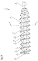
- a screw 1 is shown in side view.
- a screw body 2 of the screw 1 extends in the direction of a longitudinal axis L of the screw 1 between a proximal end 3 and a distal end 4 of the screw 1 or the screw body 2.
- An outer surface 5 of the screw body 2 is provided with an external thread 6 which is coaxial with the longitudinal axis which is intended for guiding and holding the screw 1 on the bone material of a patient.
- the pitch of the external thread 6 defines a direction of rotation D about the longitudinal axis L, at which the screw or the screw body 2 is screwed in, the distal end 4 of the screw body 2 advancing into the bone material.
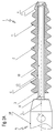
- FIGS. 2A to 2H Each screw 1 of the type described above is shown in longitudinal section in FIGS. 2A to 2H.
- a channel 7 coaxial with the longitudinal axis L is provided in the screw body 2.
- This channel 7 extends into the area of the distal end 4, in the configurations according to FIGS. 1A, 1C, 1E and 1G and 2A, 2C, 2E and 2G all the way to the distal end 4, in the configurations according to FIG. 1B, 1D, 1F and 1H as well as 2B, 2D, 2F and 2H only up to the vicinity of the distal end 4.
- a circular cylindrical auxiliary channel 12 extends between one end 11 of the channel 7 and the distal end 4, the auxiliary channel 12 of which Role is explained below.
- the channel 7 is open to the outside in order to be able to receive a shaft 8 of a screwdriver 9.
- the shaft 8 is shown in a side view in the channel 7 of the screw body 2 inserted coaxially, while the screwdriver 9 is provided with a coaxial handle 10, which is shown broken.
- the shaft 8 has a shape that complements the channel 7 and is explained in more detail below. With the help of the handle 10, the shaft 8 of the screwdriver 9 can be inserted into and removed from the channel 7, and thus the screwdriver 9 (with the shaft 8 inserted into the channel 7) can be actuated to turn the screw 1.
- the auxiliary duct 12 prevents the shaft 8 from acting as a piston when it is introduced into the duct 7 and compressing air in the duct 7.
- the auxiliary channel 12 can serve as a passage for a guide pin or a guide wire in a manner known, for example, from US-A-4950270, if the shaft 8 of the screwdriver 9 is cannulated accordingly.
- the channel 7 and the shaft 8 have rectilinear surface lines 18 which are parallel to the longitudinal axis L.
- the channel 7 and the shaft 8 can thus be written into a cylindrical enveloping volume.
- the channel 7 and the shaft 8 have a rectilinear surface line 19 which is inclined, i.e. lie at an angle to the longitudinal axis L with a half opening angle of 2 °.
- the channel 7 and the shaft 8 can therefore be written into a frusto-conical enveloping volume with a half opening angle of 2 °.
- the channel 7 and the shaft 8 have helical surface lines 20 which are each skewed to the longitudinal axis L on a cylinder which is coaxial with the longitudinal axis L.
- the channel 7 and the shaft 8 can thus be written into a cylindrical enveloping volume.
- the channel 7 and the shaft 8 have helical surface lines 21 which are each skew to the longitudinal axis L on a truncated cone with a half opening angle of 2 ° coaxial to the longitudinal axis L.
- the channel 7 and the shaft 8 can therefore be written into a frusto-conical enveloping volume with a half opening angle of 2 °.
- the channel wall 13 shows designs of the channel wall 13 as a trace thereof in the plane of a respective cross section of the screw body 2 at right angles to the longitudinal axis L.
- the longitudinal axis L corresponds to a track 14, the outer surface 5 of the screw body 2 a Track 15, the external thread 6 a track 16, and the channel wall 13 a track 17.
- This track 17 of the channel wall 13 is a closed outline which, in discrete regular rotation steps, is rotationally symmetrical about a center of symmetry formed by the track 14 of the longitudinal axis L, namely in the embodiment according to FIG. 3 in three rotation steps of 120 °, in the embodiment according to FIG 4 in four rotation steps of 90 °, in the configurations according to FIGS. 5 and 10 in eight rotation steps of 45 °, and in the configurations according to FIGS. 6 to 9 in each case in six rotation steps of 60 °.
- the channel wall 13 in the channel 7 defines an axial channel area 22 and a plurality of tab areas 23 arranged regularly around the channel area 22, the number of which in the embodiment according to FIG. 3 is three in 4 is four, eight in the embodiments according to FIGS. 5 and 10 and six in the embodiments according to FIGS. 6 to 9.
- the channel 7 thus essentially consists of the union of the axial channel area 22 and the respective tab areas 23.
- the channel wall 13 has a pair of flanks that extend radially outward essentially from the channel area 22. With respect to the direction of rotation D, a leading edge and a trailing edge 25 are defined in this pair of edges. 3 to 12, the leading flank corresponds to a track 24 and the trailing flank corresponds to a track 25.
- the tracks 24 and 25 of the two flanks each extend up to a track 26 of an end of the flap area 23 facing away from the channel area 22, so that, seen in space, the two flanks at the end of the flap region 23 converge to form an edge.
- the tracks 24 and 25 of the two flanks each extend in the vicinity of the track of the end 26 of the flap area 23 facing away from the channel area 22, but only one of these flanks extends, namely in FIG. 7 and 8 the leading flank with the trace 24 and in Fig. 10 the trailing flank with the trace 25, all the way to the trace 26 of the end of the flap area 23, so that, seen in space, the flap area 23 ends bluntly and in the area of its end an end wall with a trace 27 has.
- each lobe area 23 at least the leading flank with the track 24 has, at least in some areas, an increasingly leading shape with increasing radial distance from the track 14 of the longitudinal axis L in the direction of rotation D.
- both flanks with the tracks 24 and 25 have a shape which leads over their entire radial length with increasing radial distance in the direction of rotation D.
- the leading flank with the track 24 has a shape which grows with increasing size over approximately a radially outer half of its radial length (i.e. in the vicinity of the track 26 of the end of the flap region 23) radial distance in the direction of rotation D increasingly advanced.
- the trailing flank with the track 25 always has a shape which leads over its entire radial length with increasing radial distance in the direction of rotation D, but the end wall with the track 27 must also be taken into account. which leads in the sense mentioned in the training according to FIG. 8 and does not lead in the training according to FIGS. 7 and 10.
- each tab region 23 tapers towards the end with the track 26.
- the two flanks with the tracks 24 and 25 are at a distance from one another which tapers with increasing radial distance from the longitudinal axis L to the track 26 of the end of the flap region 23.
- This shape of the flap region 23 arises from the fact that, at least in the vicinity of the end of the flap region 23 with the track 26, the leading flank with the track 24 is concave toward the direction of rotation D and the trailing flank with the track 25 is convexly curved opposite to the direction of rotation D.
- each lobe area 23 remains approximately the same width because the two flanks with the tracks 24 and 25 are at approximately the same distance from one another. This results in an outline of the track 17 of the channel wall 13 with a paddle wheel-shaped line that is rotationally symmetrical about the track 14 of the longitudinal axis L and is drawn toward the direction of rotation D, approximately ring segment-shaped tabs of approximately constant width in corresponding number.
- the track 24 of the leading flank in each lobe area 23 is essentially straight and inclined towards the direction of rotation mentioned. This inclination of the leading edge 24 is up to 10 ° and preferably about 5 °.
- FIG. 11 the design according to FIG. 9 and in FIG. 12 the design according to FIG. 10 are shown identically, but for reasons of better readability without hatching and with only a few of the reference numerals, on the other hand with added dimensioning of an angle between the track 24 the leading flank and the track 28 of a diametrical plane passing through the end or through the track 26 thereof.
- the value of this angle is, for example, approximately 5 ° in the embodiment according to FIGS. 9 and 11 and approximately 6 ° in the embodiment according to FIGS. 10 and 12.
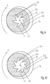
- the channel wall 13 to 16 show designs of the channel wall 13 as a trace thereof in the plane of a respective cross section of the screw body 2 at right angles to the longitudinal axis L.
- the longitudinal axis L corresponds to a track 14, the outer surface 5 of the screw body 2 to one Track 15, the external thread 6 a track 16, and the channel wall 13 a track 17.
- This track 17 of the channel wall 13 is a closed outline which, in discrete regular rotation steps, is rotationally symmetrical about a center of symmetry formed by the track 14 of the longitudinal axis L, for example in the shown embodiments according to FIGS. 13 to 16 each in six rotation steps of 60 °, which but other forms, not shown, in three rotation steps of 120 °, in four rotation steps of 90 °, in eight rotation steps of 45 ° etc., in no way exclude. It follows from the shape of the track 17 of the channel wall 13 that the channel wall 13 in the channel 7 defines an axial channel area 22 and a plurality of tab areas 23 arranged regularly around the channel area 22, the number of each of which in the embodiments shown according to FIGS. 13 to 16 is six, but in others, Training, not shown, can be three, four, eight, etc.
- the channel 7 thus essentially consists of the union of the axial channel area 22 and the respective tab areas 23.
- the channel wall 13 has a pair of flanks that extend radially outward essentially from the channel area 22. With respect to the direction of rotation D, a leading edge and a trailing edge 25 are defined in this pair of edges. 13 to 16, the leading flank corresponds to a track 24 and the trailing flank corresponds to a track 25.
- the tracks 24 and 25 of the two flanks each extend to a track 26 of an end of the flap area 23 facing away from the channel area 22, so that, seen in space, the two flanks at the end of the flap area 23 form one Edge converge.
- the tracks 24 and 25 of the two flanks each extend in the vicinity of the track of the end 26 of the flap area 23 facing away from the channel area 22, but only one of these flanks extends, namely the trailing flank with the Track 25, all the way to track 26 of the end of the flap area 23, so that, seen in space, the flap area 23 ends bluntly and has an end wall with a track 27 in the area of its end.
- each tab region 23 is asymmetrical with respect to a diametrical plane passing through the longitudinal axis L.
- each flap area 23 In order to give each flap area 23 a sawtooth-like profile with (on the course of the radial distance from the longitudinal axis L along the contour line 17) an average steeper rise in the leading flank 24 and a flatter decline in the trailing flank 25, as shown, one corresponding to the leading flank 24 Section of the outline 17 is shorter than a section of the outline 17 corresponding to the trailing flank 25.
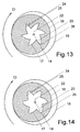
- each tab region 23 tapers towards the end with the track 26.
- the two flanks with the tracks 24 and 25 are at a distance from one another which tapers with increasing radial distance from the longitudinal axis L to the track 26 of the end of the flap region 23.
- This shape of the flap region 23 arises from the fact that, at least in the vicinity of the end of the flap region 23 with the track 26, the leading flank with the track 24 towards the direction of rotation D is less convex, i.e. is curved on average with a larger radius of curvature than the trailing flank with the track 25 is convexly curved opposite to the direction of rotation D.
- a flat formation of the leading flank with the track 24 is to be understood as the limit case of a convex track with an infinitely large radius of curvature. If the two flanks with the tracks 24 and 25 converge at the end of the lobe region 23 with the track 26 to form an edge, this results in an outline of the track 17 of the channel wall 13 with an acute, star-shaped line that runs around the track 14 of the longitudinal axis L. is rotationally symmetrical and has tines that are drawn toward the direction of rotation D in a corresponding number.
- the channel 7 as in the embodiments according to FIGS. 1A and 2A and 1B and 2B, has straight lines 18 parallel to the longitudinal axis L, the leading flank lies essentially in one plane, and the contour lines or tracks 17 of the channel wall 13 in two different cross sections of the screw body 2 perpendicular to the longitudinal axis L are congruent with each other.
- the channel 7 as in the embodiments according to FIGS. 1C and 2C as well as 1D and 2D, has straight lines 19 lying at an angle to the longitudinal axis L, the leading flank is tapered in the direction from the proximal end 3 to the distal end 4, and that Outlines or tracks 17 of the channel wall 13 in two mutually different cross sections of the screw body 2 perpendicular to the longitudinal axis L are similarity images of one another which can be brought to congruence by central stretching around the track 14 of the longitudinal axis L.
- the channel 7 as in the embodiments according to FIGS. 1E and 2E as well as 1F and 2F, has shell lines 20 twisted helically around the longitudinal axis L towards the direction of rotation D, the leading flank is also twisted helically around the longitudinal axis L towards the direction of rotation D, and the contour lines or tracks 17 of the channel wall 13 in two mutually different cross sections of the screw body 2 perpendicular to the longitudinal axis L are congruence images from one another which can be brought to congruence by pure rotation about the track 14 of the longitudinal axis L.
- the channel 7 as in the embodiments according to FIGS. 1G and 2G as well as 1H and 2H, has helical lines 21 twisted helically around the longitudinal axis L towards the direction of rotation D and at the same time lying obliquely to the longitudinal axis L
- the leading flank is also helically around the longitudinal axis L is twisted towards the direction of rotation D and also tapers in the direction from the proximal end 3 to the distal end 4
- the contour lines or traces 17 of the channel wall 13 in two mutually different cross sections of the screw body 2 at right angles to the longitudinal axis L are similarity images from one another can be brought to congruence by a combination of pure rotation and central stretching about the track 14 of the longitudinal axis L.
- the screw thread is, for example, one revolution in 10 cm.
- rejuvenation is half the opening angle up to 10 ° and preferably about 2 °.
- the shaft 8 of the screwdriver 9 Since the shaft 8 of the screwdriver 9 must be insertable and removable from the channel 7 for screwing a screw 1 into the bone material of a patient during an osteosurgical intervention, the shaft 8 has a shape complementary to the channel 7 which corresponds to the previously described configurations of FIGS Screw corresponds and can be cylindrical or frustoconical, rectilinear or twisted with a corresponding cross-section.
Abstract
Description
Die Erfindung betrifft eine Schraube aus bioabbaubarem Material für osteochirurgische Zwecke mit einem länglichen Schraubenkörper, der sich in Richtung einer Längsachse davon zwischen einem proximalen und einem distalen Ende davon erstreckt, wobei
eine Aussenfläche des Schraubenkörpers mit einem zur Längsachse koaxialen Aussengewinde versehen ist, das zum Führen und Halten der Schraube an Knochenmaterial eines Patienten bestimmt ist und eine Drehrichtung um die Längsachse für das Einschrauben des Schraubenkörpers und Vorrücken des distalen Endes in das Knochenmaterial definiert,
im Schraubenkörper ein länglicher, zur Längsachse koaxialer Kanal vorgesehen ist, der am proximalen Ende zur Aufnahme eines Schafts eines zum Drehen der Schraube bestimmten Schraubendrehers offen ist,
der Kanal eine Kanalwand aufweist, deren Form um die Längsachse in diskreten regelmässigen Drehschritten drehsymmetrisch ist und in einem Querschnitt des Schraubenkörpers rechtwinklig zur Längsachse eine Spur ergibt, welche eine um eine Spur der Längsachse in diskreten regelmässigen Drehschritten drehsymmetrische geschlossene Umrisslinie ist,
die Kanalwand einen axialen Kanalbereich und eine Mehrzahl von um den Kanalbereich regelmässig angeordneten Lappenbereichen definiert, so dass der Kanal im wesentlichen aus der Vereinigung des axialen Kanalbereiches und der Lappenbereiche besteht, und
in jedem Lappenbereich die Kanalwand ein Paar von Flanken aufweist, die sich im wesentlichen vom Kanalbereich bis in Nähe eines dem Kanalbereich abgewandten Endes des Lappenbereiches erstrecken und unter denen mit Bezug auf die genannte Drehrichtung jeweils eine vorlaufende Flanke und eine nachlaufende Flanke definiert ist.The invention relates to a screw made of biodegradable material for osteosurgical purposes with an elongated screw body which extends in the direction of a longitudinal axis thereof between a proximal and a distal end thereof, wherein
an outer surface of the screw body is provided with an external thread which is coaxial with the longitudinal axis and is intended for guiding and holding the screw on a patient's bone material and defines a direction of rotation about the longitudinal axis for screwing the screw body and advancing the distal end into the bone material,
an elongated channel coaxial with the longitudinal axis is provided in the screw body and is open at the proximal end for receiving a shaft of a screwdriver intended for turning the screw,
the channel has a channel wall, the shape of which is rotationally symmetrical about the longitudinal axis in discrete regular rotation steps and in a cross section of the screw body perpendicular to the longitudinal axis results in a track which is a closed contour which is rotationally symmetrical about a track of the longitudinal axis in discrete regular rotation steps,
the channel wall defines an axial channel area and a plurality of tab areas arranged regularly around the channel area, so that the channel essentially consists of the union of the axial channel area and the tab areas, and
in each lobe area the channel wall has a pair of flanks which extend essentially from the channel area to near an end of the lobe area facing away from the channel area and under which a leading flank and a trailing flank are defined with respect to the mentioned direction of rotation.
Ebenfalls betrifft die Erfindung einen Schraubendreher zum Eindrehen dieser Schraube in Knochenmaterial eines Patienten während eines osteochirurgischen Eingriffs, wobei der Schraubendreher mit einem Griff und einem daran befestigten länglichen Schaft versehen und der Schaft in den Kanal der Schraube einführbar und daraus entfernbar ist.The invention also relates to a screwdriver for screwing this screw into the bone material of a patient during an osteosurgical procedure, the screwdriver being provided with a handle and an elongated shaft attached thereto and the shaft being insertable into and removable from the channel of the screw.
Eine Schraube der eingangs genannten Art ist beispielsweise aus EP-A-0502698 bekannt.A screw of the type mentioned is known for example from EP-A-0502698.
Das eingangs genannte bioabbaubare, d.h. im Körper eines Patienten resorbierbare Material der Schraube ist aus EP-A-0502698 wie auch aus DE-A-2742128 und EP-A-0011528 bekannt. Im wesentlichen handelt es sich bei diesem Schraubenmaterial um ein Polylactid, ein Polyglycolid oder ein Copolymer davon, das ausgezeichnet formbar, sterilisierbar und resorbierbar ist.The biodegradable, i.e. Material of the screw that is resorbable in a patient's body is known from EP-A-0502698 as well as from DE-A-2742128 and EP-A-0011528. This screw material is essentially a polylactide, a polyglycolide or a copolymer thereof, which is extremely formable, sterilizable and resorbable.
Dieses Schraubenmaterial ist jedoch auch spröde, was bei der Anwendung der Schraube zu Problemen führt. Beim Eindrehen der Schraube in das Knochenmaterial eines Patienten während eines osteochirurgischen Eingriffs überträgt der Schraubendreher auf die Schraube Kräfte, die das spröde Schraubenmaterial übermässig beanspruchen können, mit der Folge, dass die Schraube beschädigt wird. Beispielsweise besteht bei hartem Knochen die Gefahr, dass der Schraubendreher in der Schraube durchdreht.However, this screw material is also brittle, which leads to problems when using the screw. When the screw is screwed into a patient's bone material during an osteosurgical procedure, the screwdriver transfers forces to the screw that can place excessive stress on the brittle screw material, with the result that the screw is damaged. For example, with hard bone there is a risk that the screwdriver will spin in the screw.
Zur Lösung der angesprochenen Probleme ist bereits eine Vielzahl von sternförmigen Ausbildungen des Kanals bzw. dessen Spur im Querschnitt des Schraubenkörpers vorgeschlagen worden. Eben diese Vielzahl von Formen zeigt aber auf, dass sich noch keine bisherige Schraube als zufriedenstellend erwies. Bei den bekannten Formen des Kanals sind die aneinander anliegenden, Kraft übertragenden Flanken der Lappenbereiche der Schraube und des Schraubendrehers so orientiert, dass an diesen Flanken beim Eindrehen der Schraube in Knochenmaterial radial nach aussen gerichtete Komponenten der Kraft entstehen. Auf den Körper der Schraube wirken deshalb Expansionskräfte, welche die Schraube aufzusprengen tendieren.A large number of star-shaped designs of the channel or its track in cross section of the screw body have already been proposed to solve the problems mentioned. However, this multitude of shapes shows that no previous screw has been satisfactory. In the known forms of the channel, the mutually abutting, force-transmitting flanks of the flap regions of the screw and the screwdriver are oriented in such a way that radially outward components of the force arise on these flanks when the screw is screwed into bone material. Expansion forces therefore act on the body of the screw, which tend to burst open the screw.
Aufgabe der Erfindung ist es demnach, eine Schraube der eingangs genannten Art und einen dazu passenden Schraubendreher vorzuschlagen, mit denen die erwähnten Nachteile der bekannten Schrauben und der dazu passenden Schraubendreher überwunden werden.The object of the invention is therefore a screw Propose the type mentioned and a suitable screwdriver, with which the disadvantages of the known screws and the matching screwdriver are overcome.
Zur Lösung dieser Aufgabe geht die Erfindung von der Erkenntnis aus, dass Kräfte auf die Schraube nur in Richtung des Eindrehens auszuüben sind. Bei eine osteochirurgischen Eingriff braucht eine gut sitzende Schraube der eingangs genannten Art kaum jemals entfernt zu werden. Ist eine solche Schraube zu entfernen, so ist es im allgemeinen, weil sie nicht gut sitzt, wobei sie dann eben locker sitzt und folglich keine nennenwerten Kräfte in Gegenrichtung zum Eindrehen darauf auszuüben sind, um sie wegzuschrauben. Daher braucht die Schraube gar nicht, wie bisher beim Stand der Technik, in bezug auf eine durch ihre Längsachse gehende diametrale Ebene symmetrisch zu sein.To achieve this object, the invention is based on the knowledge that forces on the screw can only be exerted in the direction of screwing. In an osteosurgical procedure, a well-fitting screw of the type mentioned at the beginning hardly ever needs to be removed. If such a screw is to be removed, it is generally because it does not fit well, in which case it then sits loosely and consequently no noteworthy forces in the opposite direction are to be exerted on it in order to screw it away. Therefore, as in the prior art, the screw need not be symmetrical with respect to a diametrical plane passing through its longitudinal axis.
Aufgrund dieser Erkenntnis wird die genannte Aufgabe bei einer Schraube der eingangs genannten Art erfindungsgemäss dadurch gelöst, dass der Kanal sich bis in den Bereich des distalen Endes erstreckt und, in einem Querschnitt des Schraubenkörpers rechtwinklig zur Längsachse betrachtet, jeder Lappenbereich in bezug auf eine durch die Längsachse gehende diametrale Ebene asymmetrisch ausgebildet ist, wobei ein der vorlaufenden Flanke entsprechender Abschnitt der Umrisslinie kürzer ist als ein der nachlaufenden Flanke entsprechender Abschnitt der Umrisslinie, so dass der Lappenbereich beim Verlauf des radialen Abstands von der Längsachse entlang der Umrisslinie ein sägezahnähnliches Profil mit durchschnittlich steilerem Anstieg der vorlaufenden Flanke und flacherem Abfall der nachlaufenden Flanke aufweist.On the basis of this knowledge, the above object is achieved according to the invention in a screw of the type mentioned at the outset in that the channel extends into the region of the distal end and, viewed in a cross section of the screw body at right angles to the longitudinal axis, each flap region with respect to one through the The longitudinal axis of the diametrical plane is asymmetrical, with a section of the contour line corresponding to the leading flank being shorter than a section of the contour line corresponding to the trailing flank, so that the area of the flap as the radial distance from the longitudinal axis runs along the contour line has a sawtooth-like profile with an average steeper profile Rise of the leading edge and flatter decrease of the trailing edge.
Ein erfindungsgemässer Schraubendreher der eingangs genannten Art ist dadurch gekennzeichnet, dass der Schaft eine zum Kanal komplementär passende Form aufweist.A screwdriver according to the invention of the type mentioned at the outset is characterized in that the shaft has a shape which complements the channel.
Bei der erfindungsgemässen Schraube ist die Übertragung der Kraft vom erfindungsgemässen Schraubendreher auf die Schraube insofern optimal, als der Schraubendreher in der Schraube auch bei grossen Drehmomenten nicht durchdreht. Auf den Körper der Schraube aus sprödem Material wirken Expansionskräfte, die geringer sind als bisher beim Stand der Technik mit radialsymmetrischen Schrauben, was dem Material der Schraube optimal angepasst ist. Dadurch verträgt eine erfindungsgemässe Schraube beim ihrem Einschrauben in Knochenmaterial grössere Drehmomente, als es mit den bisherigen Schrauben zulässig war. Der Körper der Schraube braucht nicht massiv zu sein, um die Drehmomente zu vertragen, deshalb kann sich der Kanal ganz in die Nähe vom und gegebenenfalls ganz bis zum distalen Ende erstrecken, was wiederum erlaubt, die Drehmomente auf die Schraube gleichmässig, im wesentlichen über deren ganze Länge zu übertragen und zu verteilen.In the screw according to the invention, the transmission of the force from the screwdriver according to the invention to the screw is optimal in that the screwdriver in the The screw does not turn even with high torques. Expansion forces act on the body of the screw made of brittle material, which are lower than in the prior art with radially symmetrical screws, which is optimally adapted to the material of the screw. As a result, a screw according to the invention tolerates greater torques when screwing it into bone material than was permitted with the previous screws. The body of the screw need not be massive to tolerate the torques, therefore the channel can extend very close to and possibly all the way to the distal end, which in turn allows the torques on the screw to be even, essentially above it to transmit and distribute the entire length.
In vielen Fällen wird somit auch bei hartem Knochen möglich, auf das Vorschneiden eines Gewindes im Knochen zu verzichten, was den Arbeitsablauf eines osteochirurgischen Eingriffs wesentlich vereinfacht.In many cases, even with hard bone, it is possible to do without cutting a thread in the bone, which considerably simplifies the workflow of an osteosurgical intervention.
Die nachstehend angegebenen bevorzugten Ausbildungen gewährleisten in verschiedenen Varianten eine optimale Orientierung bzw. Umlenkung der vom Schraubendreher auf die Schraube ausgeübten Kräfte, so dass auf den Schraubenkörper keine Expansionskräfte, sondern nur Zug und Schub wirken.In various variants, the preferred configurations specified below ensure optimal orientation or deflection of the forces exerted by the screwdriver on the screw, so that no expansion forces act on the screw body, but only tension and thrust.
In einer bevorzugten Ausbildung eine erfindungsgemässen Schraube erstreckt sich der Kanal bis in den Bereich des distalen Endes, und in jedem Lappenbereich weist mindestens eine der genannten Flanken zumindest in Nähe des genannten Endes des Lappenbereiches eine mit wachsendem radialem Abstand von der Längsachse in der genannten Drehrichtung zunehmend vorlaufende Form auf.In a preferred embodiment of a screw according to the invention, the channel extends into the region of the distal end, and in each flap region at least one of the flanks has an increasing radial distance from the longitudinal axis in the mentioned direction of rotation, at least in the vicinity of said end of the flap region leading form.
Bei dieser Ausbildung der erfindungsgemässen Schraube wirken auf den Körper der Schraube aus sprödem Material keine Expansionskräfte, sondern nur Zug und Schub.In this embodiment of the screw according to the invention, no expansion forces act on the body of the screw made of brittle material, but only tension and thrust.
In einer bevorzugten Ausbildung sind, in jedem Lappenbereich, die beiden Flanken in einem Abstand voneinander, der sich mit wachsendem radialem Abstand von der Längsachse zum Ende des Lappenbereiches hin verjüngt. Vorzugsweise können dabei die beiden Flanken am Ende des Lappenbereiches zu einer Kante zusammenlaufen.In a preferred embodiment, in each flap area, the two flanks are at a distance from one another which tapers with increasing radial distance from the longitudinal axis to the end of the flap area. Preferably can the two flanks converge to form an edge at the end of the flap area.
In einer weiteren bevorzugten Ausbildung ist in jedem Lappenbereich die vorlaufende Flanke zumindest in Nähe des Endes des Lappenbereiches zur genannten Drehrichtung hin konvex gekrümmt, oder sie liegt im wesentlichen in einer durch die Längsachse gehende diametrale Ebene.In a further preferred embodiment, the leading flank is convexly curved in each lobe region at least in the vicinity of the end of the lobe region in the direction of rotation mentioned, or it lies essentially in a diametrical plane passing through the longitudinal axis.
In einer noch weiteren bevorzugten Ausbildung ist in jedem Lappenbereich die vorlaufende Flanke zumindest in Nähe des Endes des Lappenbereiches zur genannten Drehrichtung hin konkav gekrümmt.In a still further preferred embodiment, the leading flank in each flap area is concavely curved toward the direction of rotation mentioned, at least in the vicinity of the end of the flap area.
In einer noch weiteren bevorzugten Ausbildung ist die nachlaufende Flanke zumindest in Nähe des Endes des Lappenbereiches entgegengesetzt zur genannten Drehrichtung konvex gekrümmt.In a still further preferred embodiment, the trailing flank is convexly curved at least in the vicinity of the end of the flap region opposite to the direction of rotation mentioned.
In einer bevorzugten Kombination der vorangehend genannten Ausbildungen kann, in einem Querschnitt des Schraubenkörpers rechtwinklig zur Längsachse, die Umrisslinie im wesentlichen einem um die Spur der Längsachse drehsymmetrischen sternförmigen Linienzug mit 3 bis 8 und vorzugsweise 6 zur genannten Drehrichtung hin vorgezogenen, gegebenenfalls sichelförmigen Zacken entsprechen.In a preferred combination of the above-mentioned designs, in a cross section of the screw body perpendicular to the longitudinal axis, the outline essentially corresponds to a star-shaped line of rotation with 3 to 8 and preferably 6, preferably crescent-shaped tines, which is rotationally symmetrical about the track of the longitudinal axis and possibly crescent-shaped toward the mentioned direction of rotation.
In einer anderen, auch bevorzugten Kombination der vorangehend genannten Ausbildungen kann, in einem Querschnitt des Schraubenkörpers rechtwinklig zur Längsachse, die Umrisslinie im wesentlichen einem um die Spur der Längsachse drehsymmetrischen schaufelradförmigen Linienzug mit 3 bis 8 und vorzugsweise 6 zur genannten Drehrichtung hin vorgezogenen, gegebenenfalls etwa sichelförmigen Lappen entsprechen.In another, also preferred, combination of the above-mentioned configurations, in a cross section of the screw body perpendicular to the longitudinal axis, the outline can essentially be drawn in a paddle wheel-shaped line with 3 to 8, and preferably 6, rotationally symmetrical about the track of the longitudinal axis, possibly approximately in the direction of rotation mentioned correspond to crescent-shaped lobes.
In einer weiteren bevorzugten Ausbildung sind in jedem Lappenbereich die beiden Flanken in etwa gleichbleibendem Abstand voneinander. Vorzugsweise kann dabei, in einem Querschnitt des Schraubenkörpers rechtwinklig zur Längsachse, die Umrisslinie im wesentlichen einem um die Spur der Längsachse drehsymmetrischen schaufelradförmigen Linienzug mit 3 bis 8 und vorzugsweise 6 zur genannten Drehrichtung hin vorgezogenen, etwa ringsegmentförmigen Lappen von etwa gleichbleibender Breite entsprechen.In a further preferred embodiment, the two flanks in each lobe area are at approximately the same distance from one another. Preferably, in a cross section of the screw body at right angles to the longitudinal axis, the outline can essentially be drawn in a paddle wheel-shaped line with 3 to 8, and preferably 6, rotationally symmetrical about the track of the longitudinal axis, preferably towards the mentioned direction of rotation, correspond approximately to ring segment-shaped tabs of approximately constant width.
In einer noch weiteren bevorzugten Ausbildung ist in jedem Lappenbereich in einem Querschnitt des Schraubenkörpers rechtwinklig zur Längsachse eine Spur der vorlaufenden Flanke im wesentlichen geradlinig und zur genannten Drehrichtung hin geneigt. Vorzugsweise kann dabei die Neigung der vorlaufenden Flanke bis zu 10° und vorzugsweise etwa 5° betragen.In a still further preferred embodiment, a trace of the leading flank is essentially rectilinear and inclined towards the direction of rotation in each lobe area in a cross section of the screw body perpendicular to the longitudinal axis. The inclination of the leading flank can preferably be up to 10 ° and preferably about 5 °.
In einer ersten bevorzugten Weiterbildung einer der vorangehend genannten Ausbildungen sind die Flanken schraubenförmig um die Längsachse zur genannten Drehrichtung hin verdrillt, derart, dass in zwei voneinander verschiedenen Querschnitten des Schraubenkörpers rechtwinklig zur Längsachse die Umrisslinien Kongruenzabbildungen voneinander darstellen, die durch reine Drehung um die Spur der Längsachse zur Kongruenz bringbar sind. Auf diese Weise wird zwischen dem Schraubenkörper und dem Schaft des Schraubendrehers eine verdrillte Kontaktfläche gebildet, welche die vom Schraubendreher auf die Schraube ausgeübten Drehkräfte so umlenkt, dass die erfindungsgemässe Schraube beim Einschrauben noch grössere Drehmomente verträgt als bei einer geraden axialen Ausführung der Kontaktfläche.In a first preferred development of one of the above-mentioned configurations, the flanks are twisted helically around the longitudinal axis in the direction of rotation mentioned, in such a way that in two different cross sections of the screw body perpendicular to the longitudinal axis, the outline lines represent congruence figures from one another, which are caused by pure rotation around the track of the Longitudinal axis are congruent. In this way, a twisted contact surface is formed between the screw body and the shaft of the screwdriver, which redirects the rotational forces exerted by the screwdriver on the screw so that the screw according to the invention can withstand even greater torques when screwing in than with a straight axial design of the contact surface.
In einer zweiten bevorzugten Weiterbildung einer der vorangehend genannten Ausbildungen sind die Flanken in Richtung vom proximalen zum distalen Ende hin verjüngt, derart, dass in zwei voneinander verschiedenen Querschnitten des Schraubenkörpers rechtwinklig zur Längsachse die Umrisslinien Ähnlichkeitsabbildungen voneinander darstellen, die durch zentrische Streckung um die Spur der Längsachse zur Kongruenz bringbar sind. Dadurch kann der Schaft des Schraubendrehers so bemessen werden, dass er ohne Spiel in den Kanal der Schraube passt und dennoch leicht aus dem Schraubenkörper herausgezogen werden kann, was insbesondere bei einer Ausbildung mit der im vorangehenden erwähnten verdrillten Kontaktfläche von grossem Nutzen ist. Wenn dann auch noch vorgesehen wird, dass sich der Kanal nicht ganz bis zum distalen Ende des Schraubenkörpers erstreckt, so füllt der Schaft des in die Schraube eingesetzten Schraubendrehers den Kanal des Schraubenkörpers nicht nur im Querschnitt rechtwinklig zur Längsachse genau, sondern auch in Richtung der Längsachse, bis das freie Ende des Schraubendrehers am distalen Abschluss des Kanals anliegt, wodurch mit Sicherheit vermieden wird, dass der Schaft des Schraubendrehers den Schraubenkörper wie einen Dübel aufspreizt und dabei das spröde Schraubenmaterial sprengt.In a second preferred development of one of the above-mentioned configurations, the flanks are tapered in the direction from the proximal to the distal end, such that in two different cross sections of the screw body perpendicular to the longitudinal axis, the outline lines represent similarity images from one another, which are caused by central stretching around the track of the Longitudinal axis are congruent. As a result, the shaft of the screwdriver can be dimensioned such that it fits into the channel of the screw without play and can nevertheless be easily pulled out of the screw body, which is particularly useful in the case of a design with the twisted contact surface mentioned above. If it is then also provided that the channel does not extend all the way to the distal end of the screw body, the shaft of the screwdriver inserted into the screw fills the channel of the screw body precisely not only in cross section at right angles to the longitudinal axis, but also in the direction of the longitudinal axis until the free end of the screwdriver lies against the distal end of the channel, thereby ensuring with certainty it is avoided that the shaft of the screwdriver spreads the screw body like a dowel and thereby bursts the brittle screw material.
In einer bevorzugten Kombination der genannten ersten und zweiten Weiterbildungen sind die Flanken sowohl verdrillt als auch verjüngt, derart, dass in zwei voneinander verschiedenen Querschnitten des Schraubenkörpers rechtwinklig zur Längsachse die Umrisslinien Ähnlichkeitsabbildungen voneinander darstellen, die durch eine Kombination von reiner Drehung und zentrischer Streckung um die Spur der Längsachse zur Kongruenz bringbar sind.In a preferred combination of the first and second developments mentioned, the flanks are both twisted and tapered, such that in two different cross sections of the screw body perpendicular to the longitudinal axis, the outline lines represent similarity images from one another, which are due to a combination of pure rotation and central stretching around the The longitudinal axis track can be brought to congruence.
Vorzugsweise entspricht die Verjüngung in Richtung vom proximalen zum distalen Ende hin einem halben Öffnungswinkel von bis zu 10° und vorzugsweise von etwa 2°. Bei einer solchen Bemessung der Verjüngung wird eine Sprengung des Schraubenkörpers durch den Schaft des Schraubendrehers auch dann vermieden, wenn der Kanal sich durchgehend bis zum distalen Ende des Schraubenkörpers erstreckt und dort offen ist, oder auch wenn der distale Abschluss des Kanals unter dem Druck des Schafts des Schraubendrehers nachgibt.The taper in the direction from the proximal to the distal end preferably corresponds to a half opening angle of up to 10 ° and preferably of approximately 2 °. With such a dimensioning of the taper, the screw body is prevented from exploding by the shaft of the screwdriver even if the channel extends continuously to the distal end of the screw body and is open there, or even if the distal end of the channel is under the pressure of the shaft of the screwdriver gives way.
Nachstehend werden Ausbildungsbeispiele der Erfindung anhand der Zeichnung näher erläutert. Es zeigen:
- Fig. 1A bis 1H
- eine erste bis achte Ausbildung einer erfindungsgemässen Schraube, in Seitenansicht;
- Fig. 2A bis 2H
- die Ausbildungen der erfindungsgemässen Schraube gemäss den entsprechenden Fig. 1A bis 1H, im Längsschnitt und mit einem darin eingesetzten, gebrochen dargestellten erfindungsgemässen Schraubendreher;
- Fig. 3 bis 10
- je einen Querschnitt der erfindungsgemässen Schraube entsprechend der Linie A-A der Fig. 1A bis 1H zur Veranschaulichung von jeweiligen Ausbildungen einer Form einer Kanalwand der erfindungsgemässen Schraube;
- Fig. 11 und 12
- die jeweils gleiche Darstellung wie in Fig. 9 und 10, mit Einfügung nur einiger Bezugszeichen und hinzugefügter Bemessung eines Winkels; und
- Fig. 13 bis 16
- je einen Querschnitt der erfindungsgemässen Schraube entsprechend der Linie A-A der Fig. 1A bis 1H zur Veranschaulichung von jeweiligen Ausbildungen einer Form einer Kanalwand der erfindungsgemässen Schraube.
- 1A to 1H
- a first to eighth embodiment of a screw according to the invention, in side view;
- 2A to 2H
- the designs of the screw according to the invention according to the corresponding FIGS. 1A to 1H, in longitudinal section and with a screwdriver according to the invention inserted therein and shown broken;
- 3 to 10
- A cross-section of the screw according to the invention according to the line AA of Figures 1A to 1H to illustrate respective designs of a shape of a channel wall of the screw according to the invention.
- 11 and 12
- the same representation as in Figures 9 and 10, with the insertion of only a few reference numerals and added dimensioning of an angle. and
- 13 to 16
- A cross section of the screw according to the invention according to the line AA of FIGS. 1A to 1H to illustrate the respective configurations of a shape of a channel wall of the screw according to the invention.
Die in den Figuren dargestellten erfindungsgemässen Schrauben sind aus einem bioabbaubaren Material für osteochirurgische Zwecke beispielsweise hergestellt. Als Beispiel eines solchen Materials wird hier das im Handel erhältliche und von der Firma ArgoMedical AG, CH-6330 Cham, unter dem Warenzeichen PHUSILINE vertriebene Material angegeben, was jedoch andere bioabbaubaren Materialien nicht ausschliesst. Die Verarbeitung dieses bioabbaubaren Material zur gewünschten Form erfolgt auf bekannte Weise beispielsweise durch Spritzguss, Heissverformung, Heisspressen und ähnlichen Verfahren bei einer dazu geeigneten Temperatur, die meist im Bereich zwischen Raumtemperatur und 100°C auszuwählen ist.The screws according to the invention shown in the figures are made of a biodegradable material for osteosurgical purposes, for example. As an example of such a material, the material commercially available and sold by ArgoMedical AG, CH-6330 Cham, under the trademark PHUSILINE is given, but this does not exclude other biodegradable materials. This biodegradable material is processed to the desired shape in a known manner, for example by injection molding, hot shaping, hot pressing and similar processes at a suitable temperature, which is usually to be selected in the range between room temperature and 100 ° C.
In Fig. 1A bis 1H ist eine Schraube 1 in Seitenansicht dargestellt. Ein Schraubenkörper 2 der Schraube 1 erstreckt sich in Richtung einer Längsachse L der Schraube 1 zwischen einem proximalen Ende 3 und einem distalen Ende 4 der Schraube 1 bzw. des Schraubenkörpers 2. Eine Aussenfläche 5 des Schraubenkörpers 2 ist mit einem zur Längsachse koaxialen Aussengewinde 6 versehen, das zum Führen und Halten der Schraube 1 an Knochenmaterial eines Patienten bestimmt ist. Die Steigung des Aussengewindes 6 definiert eine Drehrichtung D um die Längsachse L, bei welcher die Schraube bzw. der Schraubenkörper 2 eingeschraubt wird, wobei das distale Ende 4 des Schraubenkörpers 2 in das Knochenmaterial vorrückt.1A to 1H, a
Je eine Schraube 1 der vorangehend beschriebenen Art ist in Fig. 2A bis 2H im Längsschnitt dargestellt.Each
Im Schraubenkörper 2 ist ein zur Längsachse L koaxialer Kanal 7 vorgesehen. Dieser Kanal 7 erstreckt sich bis in den Bereich des distalen Endes 4, in den Ausbildungen nach Fig. 1A, 1C, 1E und 1G sowie 2A, 2C, 2E und 2G ganz bis zum distalen Ende 4, in den Ausbildungen nach Fig. 1B, 1D, 1F und 1H sowie 2B, 2D, 2F und 2H nur bis in die Nähe des distalen Endes 4. Im letztgenannten Fall erstreckt sich zwischen einem Ende 11 des Kanals 7 und dem distalen Ende 4 ein zur Längsachse L koaxialer kreiszylindrischer Hilfskanal 12, dessen Rolle weiter unten erläutert wird.A
Am proximalen Ende 3 ist der Kanal 7 gegen aussen offen, um einen Schaft 8 eines Schraubendrehers 9 aufnehmen zu können. In Fig. 2A bis 2H ist der Schaft 8 in Seitenansicht im Kanal 7 des Schraubenkörpers 2 koaxial eingesetzt dargestellt, während der Schraubendreher 9 mit einem koaxialen Griff 10 versehen ist, der gebrochen dargestellt ist. Der Schaft 8 hat eine zum Kanal 7 komplementär passende Form, die im nachstehenden näher erläutert wird. Mit Hilfe des Griffs 10 ist der der Schaft 8 des Schraubendrehers 9 in den Kanal 7 einführbar und daraus entfernbar und somit der Schraubendreher 9 (bei in den Kanal 7 eingeführtem Schaft 8) zum Drehen der Schraube 1 betätigbar.At the
Der Hilfskanal 12 nach Fig. 1B, 1D, 1F und 1H sowie 2B, 2D, 2F und 2H vermeidet, dass der Schaft 8 bei seiner Einführung in den Kanal 7 als Kolben wirkt und Luft im Kanal 7 komprimiert. So braucht bei der Einführung des Schafts 8 in den Kanal 7 keine Luft in einem Spalt zwischen dem Schaft 8 und dem Kanal 7 zu entweichen, was ermöglicht, zwischen dem Schaft 8 und dem Kanal 7 bzw. einer Kanalwand 13 des Kanals 7 ein nur sehr kleines Spiel zu lassen und folglich eine optimale Übertragung der Kraft vom Schraubendreher 9 auf die Schraube 1 zu gewährleisten. Zudem kann der Hilfskanal 12 auf beispielsweise aus US-A-4950270 bekannte Weise als Durchgang für einen Führungsstift oder einen Führungsdraht dienen, wenn der Schaft 8 des Schraubendrehers 9 entsprechend kanüliert ist.The
In den Ausbildungen nach Fig. 1A und 2A sowie 1B und 2B weisen der Kanal 7 und der Schaft 8 geradlinige Mantellinien 18 auf, die parallel zur Längsachse L sind. Der Kanal 7 und der Schaft 8 sind also in ein zylindrisches umhüllendes Volumen einschreibbar.1A and 2A and 1B and 2B, the
In den Ausbildungen nach Fig. 1C und 2C sowie 1D und 2D weisen der Kanal 7 und der Schaft 8 geradlinige Mantellinie 19 auf, die schräg d.h. im Winkel zur Längsachse L mit einem halben Öffnungswinkel von 2° liegen. Der Kanal 7 und der Schaft 8 sind also in ein kegelstumpfförmiges umhüllendes Volumen mit einem halben Öffnungswinkel von 2° einschreibbar.1C and 2C as well as 1D and 2D, the
In den Ausbildungen nach Fig. 1E und 2E sowie 1F und 2F weisen der Kanal 7 und der Schaft 8 schraubenförmige Mantellinien 20 auf, die jeweils windschief zur Längsachse L auf einem zur Längsachse L koaxialen Zylinder liegen. Der Kanal 7 und der Schaft 8 sind also in ein zylindrisches umhüllendes Volumen einschreibbar.1E and 2E as well as 1F and 2F, the
In den Ausbildungen nach Fig. 1G und 2G sowie 1H und 2H weisen der Kanal 7 und der Schaft 8 schraubenförmige Mantellinien 21 auf, die jeweils windschief zur Längsachse L auf einem zur Längsachse L koaxialen Kegelstumpf mit einem halben Öffnungswinkel von 2° liegen. Der Kanal 7 und der Schaft 8 sind also in ein kegelstumpfförmiges umhüllendes Volumen mit einem halben Öffnungswinkel von 2° einschreibbar.In the embodiments according to FIGS. 1G and 2G as well as 1H and 2H, the
Fig. 3 bis 10 zeigen Ausbildungen der Kanalwand 13 als Spur davon in der Ebene eines jeweiligen Querschnitts des Schraubenkörpers 2 rechtwinklig zur Längsachse L. Im jeweiligen Querschnitt bzw. in dessen Ebene entspricht der Längsachse L eine Spur 14, der Aussenfläche 5 des Schraubenkörpers 2 eine Spur 15, dem Aussengewinde 6 eine Spur 16, und der Kanalwand 13 eine Spur 17.3 to 10 show designs of the
Diese Spur 17 der Kanalwand 13 ist eine geschlossene Umrisslinie, die in diskreten regelmässigen Drehschritten um ein von der Spur 14 der Längsachse L gebildetes Symmetriezentrum drehsymmetrisch ist, nämlich in der Ausbildung gemäss Fig. 3 in drei Drehschritten von 120°, in der Ausbildung gemäss Fig. 4 in vier Drehschritten von 90°, in den Ausbildungen gemäss Fig. 5 und 10 in acht Drehschritten von 45°, und in den Ausbildungen gemäss Fig. 6 bis 9 jeweils in sechs Drehschritten von 60°. Aus der Form der Spur 17 der Kanalwand 13 ergibt sich, dass die Kanalwand 13 im Kanal 7 einen axialen Kanalbereich 22 und eine Mehrzahl von um den Kanalbereich 22 regelmässig angeordneten Lappenbereichen 23 definiert, deren Anzahl in der Ausbildung gemäss Fig. 3 gleich drei, in der Ausbildung gemäss Fig. 4 gleich vier, in den Ausbildungen gemäss Fig. 5 und 10 gleich acht und in den Ausbildungen gemäss Fig. 6 bis 9 jeweils gleich sechs ist. Somit besteht der Kanal 7 im wesentlichen aus der Vereinigung des axialen Kanalbereiches 22 und der jeweiligen Lappenbereiche 23.This
In jedem Lappenbereich 23 weist die Kanalwand 13 ein Paar von Flanken auf, die sich im wesentlichen vom Kanalbereich 22 ausgehend radial nach aussen erstrecken. Mit Bezug auf die Drehrichtung D werden in diesem Paar von Flanken eine vorlaufende Flanke und eine nachlaufende Flanke 25 definiert. In den Ausbildungen gemäss Fig. 3 bis 12 entspricht der vorlaufenden Flanke eine Spur 24 und der nachlaufenden Flanke eine Spur 25.In each
In den Ausbildungen gemäss Fig. 3 bis 6 sowie gemäss Fig. 9 erstrecken sich die Spuren 24 und 25 der beiden Flanken jeweils bis zu einer Spur 26 eines dem Kanalbereich 22 abgewandten Endes des Lappenbereiches 23, so dass im Raume gesehen die beiden Flanken am Ende des Lappenbereiches 23 zu einer Kante zusammenlaufen. In den Ausbildungen gemäss Fig. 7, 8 und 10 erstrecken sich die Spuren 24 und 25 der beiden Flanken jeweils bis in Nähe der Spur des dem Kanalbereich 22 abgewandten Endes 26 des Lappenbereiches 23, jedoch erstreckt sich nur eine dieser Flanken, nämlich in Fig. 7 und 8 die vorlaufende Flanke mit der Spur 24 und in Fig. 10 die nachlaufende Flanke mit der Spur 25, ganz bis zur Spur 26 des Endes des Lappenbereiches 23, so dass im Raume gesehen der Lappenbereich 23 stumpf endet und im Bereich seines Endes eine Abschlusswandung mit einer Spur 27 aufweist.3 to 6 and FIG. 9, the
Erfindungswesentlich ist dabei, dass in jedem Lappenbereich 23 zumindest die vorlaufende Flanke mit der Spur 24 zumindest bereichsweise eine mit wachsendem radialem Abstand von der Spur 14 der Längsachse L in der Drehrichtung D zunehmend vorlaufende Form aufweist. In den Ausbildungen gemäss Fig. 7, 9 und 10 haben beide Flanken mit den Spuren 24 und 25 eine Form, die über ihre ganze radiale Länge mit wachsendem radialem Abstand in der Drehrichtung D zunehmend voreilt. In den Ausbildungen gemäss Fig. 3 bis 6 sowie gemäss Fig. 8 hat die vorlaufende Flanke mit der Spur 24 eine Form, die etwa über einer radial äusseren Hälfte ihrer radialen Länge (also in Nähe der Spur 26 des Endes des Lappenbereiches 23) mit wachsendem radialem Abstand in der Drehrichtung D zunehmend voreilt. In den Ausbildungen gemäss Fig. 3 bis 10 hat die nachlaufende Flanke mit der Spur 25 stets eine Form, die über ihre ganze radiale Länge mit wachsendem radialem Abstand in der Drehrichtung D zunehmend voreilt, jedoch ist auch die Abschlusswandung mit der Spur 27 zu berücksichtigen, welche im genannten Sinne bei der Ausbildung gemäss Fig. 8 voreilt und bei den Ausbildungen gemäss Fig. 7 und 10 nicht voreilt.It is essential to the invention that in each
Es wird hier noch klargestellt, was unter "Voreilen einer Fläche in einer vorgegebenen Drehrichtung mit wachsendem radialem Abstand von einer Achse" zu verstehen ist. In einem Querschnitt der Fläche rechtwinklig zur Achse werden zwei Laufpunkte einer Spur der Fläche betrachtet. Ausgehend von der Achse ist ein erster Radius auf den zur Achse näheren Laufpunkt und ein zweiter Radius auf den von der Achse entfernteren Laufpunkt gerichtet. Um den ersten Radius mit dem zweiten Radius in Kongruenz zu bringen, wird eine Drehung benötigt. Erfolgt diese Drehung in der vorgegebenen Drehrichtung, so ist die Spur bzw. die Fläche in der vorgegebenen Drehrichtung "voreilend", weil in der vorgegebenen Drehrichtung und von der Achse aus betrachtet der entferntere Laufpunkt "vor" dem näheren Laufpunkt liegt.It is also clarified here what is to be understood by "advancing a surface in a given direction of rotation with increasing radial distance from an axis". In a cross section of the surface perpendicular to the axis, two running points of a track of the surface are considered. Starting from the axis, a first radius is directed to the running point closer to the axis and a second radius is directed to the running point further away from the axis. A rotation is required to bring the first radius into congruence. If this rotation takes place in the specified direction of rotation, the track or surface is in the specified direction Direction of rotation "leading", because in the given direction of rotation and from the axis, the more distant running point lies "before" the closer running point.
In den Ausbildungen gemäss Fig. 3 bis 6 sowie gemäss Fig. 8 bis 10 verjüngt sich jeder Lappenbereich 23 zu seinem Ende mit der Spur 26 hin. In anderen Worten, in diesen Ausbildungen sind die beiden Flanken mit den Spuren 24 und 25 in einem Abstand voneinander, der sich mit wachsendem radialem Abstand von der Längsachse L zur Spur 26 des Endes des Lappenbereiches 23 hin verjüngt. Diese Form des Lappenbereiches 23 kommt dadurch zustande, dass zumindest in Nähe des Endes des Lappenbereiches 23 mit der Spur 26 die vorlaufende Flanke mit der Spur 24 zur Drehrichtung D hin konkav und die nachlaufende Flanke mit der Spur 25 entgegengesetzt zur Drehrichtung D konvex gekrümmt ist. Wenn die beiden Flanken mit den Spuren 24 und 25 am Ende des Lappenbereiches 23 mit der Spur 26 zu einer Kante zusammenlaufen, ergibt sich daraus eine Umrisslinie der Spur 17 der Kanalwand 13 mit einem sternförmigen Linienzug, der um die Spur 14 der Längsachse L drehsymmetrisch ist und zur Drehrichtung D hin vorgezogene sichelförmige Zacken in entsprechender Anzahl aufweist. Im gegenteiligen Fall, wenn die beiden Flanken mit den Spuren 24 und 25 am Ende des Lappenbereiches 23 mit der Spur 26 nicht zu einer Kante zusammenlaufen, ergibt sich daraus eine Umrisslinie der Spur 17 der Kanalwand 13 mit einem schaufelradförmigen Linienzug, der um die Spur 14 der Längsachse L drehsymmetrisch ist und zur Drehrichtung D hin vorgezogene etwa sichelförmige Lappen in entsprechender Anzahl aufweist.In the embodiments according to FIGS. 3 to 6 and according to FIGS. 8 to 10, each
In der Ausbildung gemäss Fig. 7 bleibt hingegen jeder Lappenbereich 23 etwa gleich breit, weil darin die beiden Flanken mit den Spuren 24 und 25 in etwa gleichbleibendem Abstand voneinander sind. Es ergibt sich daraus eine Umrisslinie der Spur 17 der Kanalwand 13 mit einem schaufelradförmigen Linienzug, der um die Spur 14 der Längsachse L drehsymmetrisch ist und zur Drehrichtung D hin vorgezogene, etwa ringsegmentförmige Lappen von etwa gleichbleibender Breite in entsprechender Anzahl aufweist.In the embodiment according to FIG. 7, on the other hand, each
In den Ausbildungen gemäss Fig. 9 und 10 ist in jedem Lappenbereich 23 die Spur 24 der vorlaufenden Flanke im wesentlichen geradlinig und zur genannten Drehrichtung hin geneigt. Diese Neigung der vorlaufenden Flanke 24 beträgt bis zu 10° und vorzugsweise etwa 5°. In Fig. 11 ist die Ausbildung gemäss Fig. 9 und in Fig. 12 die Ausbildung gemäss Fig. 10 identisch dargestellt, jedoch aus Gründen der besseren Lesbarkeit ohne Schraffur und mit nur einigen der Bezugszeichen, hingegen mit hinzugefügter Bemessung eines Winkels zwischen der Spur 24 der vorlaufenden Flanke und der Spur 28 einer durch das Ende bzw. durch dessen Spur 26 gehenden diametralen Ebene. Der Wert dieses Winkels ist beispielsweise in der Ausbildung gemäss Fig. 9 und 11 gleich etwa 5° und in der Ausbildung gemäss Fig. 10 und 12 gleich etwa 6°.In the designs according to FIGS. 9 and 10, the
Fig. 13 bis 16 zeigen Ausbildungen der Kanalwand 13 als Spur davon in der Ebene eines jeweiligen Querschnitts des Schraubenkörpers 2 rechtwinklig zur Längsachse L. Im jeweiligen Querschnitt bzw. in dessen Ebene entspricht der Längsachse L eine Spur 14, der Aussenfläche 5 des Schraubenkörpers 2 eine Spur 15, dem Aussengewinde 6 eine Spur 16, und der Kanalwand 13 eine Spur 17.13 to 16 show designs of the
Diese Spur 17 der Kanalwand 13 ist eine geschlossene Umrisslinie, die in diskreten regelmässigen Drehschritten um ein von der Spur 14 der Längsachse L gebildetes Symmetriezentrum drehsymmetrisch ist, beispielsweise in den gezeigten Ausbildungen gemäss Fig. 13 bis 16 jeweils in sechs Drehschritten von 60°, was aber andere, nicht dargestellte Ausbildungen beispielsweise in drei Drehschritten von 120°, in vier Drehschritten von 90°, in acht Drehschritten von 45° usw. keineswegs ausschliesst. Aus der Form der Spur 17 der Kanalwand 13 ergibt sich, dass die Kanalwand 13 im Kanal 7 einen axialen Kanalbereich 22 und eine Mehrzahl von um den Kanalbereich 22 regelmässig angeordneten Lappenbereichen 23 definiert, deren Anzahl in den gezeigten Ausbildungen gemäss Fig. 13 bis 16 jeweils gleich sechs ist, aber in anderen, nicht dargestellten Ausbildungen gleich drei, vier, acht usw. sein kann. Somit besteht der Kanal 7 im wesentlichen aus der Vereinigung des axialen Kanalbereiches 22 und der jeweiligen Lappenbereiche 23.This
In jedem Lappenbereich 23 weist die Kanalwand 13 ein Paar von Flanken auf, die sich im wesentlichen vom Kanalbereich 22 ausgehend radial nach aussen erstrecken. Mit Bezug auf die Drehrichtung D werden in diesem Paar von Flanken eine vorlaufende Flanke und eine nachlaufende Flanke 25 definiert. In den Ausbildungen gemäss Fig. 13 bis 16 entspricht der vorlaufenden Flanke eine Spur 24 und der nachlaufenden Flanke eine Spur 25.In each
In den Ausbildungen gemäss Fig. 13 und 15 erstrecken sich die Spuren 24 und 25 der beiden Flanken jeweils bis zu einer Spur 26 eines dem Kanalbereich 22 abgewandten Endes des Lappenbereiches 23, so dass im Raume gesehen die beiden Flanken am Ende des Lappenbereiches 23 zu einer Kante zusammenlaufen. In den Ausbildungen gemäss Fig. 14 und 16 erstrecken sich die Spuren 24 und 25 der beiden Flanken jeweils bis in Nähe der Spur des dem Kanalbereich 22 abgewandten Endes 26 des Lappenbereiches 23, jedoch erstreckt sich nur eine dieser Flanken, nämlich die nachlaufende Flanke mit der Spur 25, ganz bis zur Spur 26 des Endes des Lappenbereiches 23, so dass im Raume gesehen der Lappenbereich 23 stumpf endet und im Bereich seines Endes eine Abschlusswandung mit einer Spur 27 aufweist.13 and 15, the
Erfindungswesentlich ist dabei, dass im dargestellten Querschnitt des Schraubenkörpers 2 rechtwinklig zur Längsachse L betrachtet, jeder Lappenbereich 23 in bezug auf eine durch die Längsachse L gehende diametrale Ebene asymmetrisch ausgebildet ist. Um jedem Lappenbereich 23 ein sägezahnähnliches Profil mit (beim Verlauf des radialen Abstands von der Längsachse L entlang der Umrisslinie 17) durchschnittlich steilerem Anstieg der vorlaufenden Flanke 24 und flacherem Abfall der nachlaufenden Flanke 25 zu geben, ist wie dargestellt jeweils ein der vorlaufenden Flanke 24 entsprechender Abschnitt der Umrisslinie 17 kürzer ausgebildet als ein der nachlaufenden Flanke 25 entsprechender Abschnitt der Umrisslinie 17.It is essential to the invention that viewed in the cross section of the
In den gezeigten Ausbildungen gemäss Fig. 13 bis 16 verjüngt sich jeder Lappenbereich 23 zu seinem Ende mit der Spur 26 hin. In anderen Worten, die beiden Flanken mit den Spuren 24 und 25 sind in einem Abstand voneinander, der sich mit wachsendem radialem Abstand von der Längsachse L zur Spur 26 des Endes des Lappenbereiches 23 hin verjüngt. Diese Form des Lappenbereiches 23 kommt dadurch zustande, dass zumindest in Nähe des Endes des Lappenbereiches 23 mit der Spur 26 die vorlaufende Flanke mit der Spur 24 zur Drehrichtung D hin weniger konvex d.h. durchschnittlich mit grösserem Krümmungsradius gekrümmt ist, als die nachlaufende Flanke mit der Spur 25 entgegengesetzt zur Drehrichtung D konvex gekrümmt ist. In diesem Zusammenhang ist eine ebene Ausbildung der vorlaufenden Flanke mit der Spur 24 als Grenzfall einer konvexen Spur mit unendlich grossem Krümmungsradius zu verstehen. Wenn die beiden Flanken mit den Spuren 24 und 25 am Ende des Lappenbereiches 23 mit der Spur 26 zu einer Kante zusammenlaufen, ergibt sich daraus eine Umrisslinie der Spur 17 der Kanalwand 13 mit einem spitzen, sternförmigen Linienzug, der um die Spur 14 der Längsachse L drehsymmetrisch ist und zur Drehrichtung D hin vorgezogene Zacken in entsprechender Anzahl aufweist. Im gegenteiligen Fall, wenn die beiden Flanken mit den Spuren 24 und 25 am Ende des Lappenbereiches 23 mit der Spur 26 nicht zu einer Kante zusammenlaufen, ergibt sich daraus eine Umrisslinie der Spur 17 der Kanalwand 13 mit einem stumpfen Linienzug, der um die Spur 14 der Längsachse L drehsymmetrisch ist und zur Drehrichtung D hin vorgezogene Lappen in entsprechender Anzahl aufweist.13 to 16, each
Hat der Kanal 7, wie in den Ausbildungen nach Fig. 1A und 2A sowie 1B und 2B, geradlinige und zur Längsachse L parallele Mantellinien 18, so liegt die vorlaufende Flanke im wesentlichen in einer Ebene, und die Umrisslinien bzw. Spuren 17 der Kanalwand 13 in zwei voneinander verschiedenen Querschnitte des Schraubenkörpers 2 rechtwinklig zur Längsachse L sind miteinander kongruent.If the
Hat der Kanal 7, wie in den Ausbildungen nach Fig. 1C und 2C sowie 1D und 2D, geradlinige und zur Längsachse L schräg liegende Mantellinien 19, so ist die vorlaufende Flanke in Richtung vom proximalen Ende 3 zum distalen Ende 4 hin verjüngt, und die Umrisslinien bzw. Spuren 17 der Kanalwand 13 in zwei voneinander verschiedenen Querschnitte des Schraubenkörpers 2 rechtwinklig zur Längsachse L sind Ähnlichkeitsabbildungen voneinander, die durch zentrische Streckung um die Spur 14 der Längsachse L zur Kongruenz bringbar sind.If the
Hat der Kanal 7, wie in den Ausbildungen nach Fig. 1E und 2E sowie 1F und 2F, schraubenförmig um die Längsachse L zur Drehrichtung D hin verdrillte Mantellinien 20, so ist auch die vorlaufende Flanke schraubenförmig um die Längsachse L zur Drehrichtung D hin verdrillt, und die Umrisslinien bzw. Spuren 17 der Kanalwand 13 in zwei voneinander verschiedenen Querschnitte des Schraubenkörpers 2 rechtwinklig zur Längsachse L sind Kongruenzabbildungen voneinander, die durch reine Drehung um die Spur 14 der Längsachse L zur Kongruenz bringbar sind.If the
Hat schliesslich der Kanal 7, wie in den Ausbildungen nach Fig. 1G und 2G sowie 1H und 2H, schraubenförmig um die Längsachse L zur Drehrichtung D hin verdrillte und gleichzeitig windschief zur Längsachse L liegende Mantellinien 21, so ist auch die vorlaufende Flanke sowohl schraubenförmig um die Längsachse L zur Drehrichtung D hin verdrillt als auch in Richtung vom proximalen Ende 3 zum distalen Ende 4 hin verjüngt, und die Umrisslinien bzw. Spuren 17 der Kanalwand 13 in zwei voneinander verschiedenen Querschnitte des Schraubenkörpers 2 rechtwinklig zur Längsachse L sind Ähnlichkeitsabbildungen voneinander, die durch eine Kombination von reiner Drehung und zentrischer Streckung um die Spur 14 der Längsachse L zur Kongruenz bringbar sind.Finally, if the
Im Falle der Verdrillung beträgt der Schraubengang von beispielsweise einer Umdrehung in 10 cm. Im Falle der Verjüngung beträgt der halbe Öffnungswinkel bis zu 10° und vorzugsweise etwa 2°.In the case of twisting, the screw thread is, for example, one revolution in 10 cm. In the case of rejuvenation is half the opening angle up to 10 ° and preferably about 2 °.
Da der Schaft 8 des Schraubendrehers 9 zum Eindrehen einer Schraube 1 in Knochenmaterial eines Patienten während eines osteochirurgischen Eingriffs in den Kanal 7 einführbar und daraus entfernbar sein muss, weist der Schaft 8 eine zum Kanal 7 komplementär passende Form auf, die den vorangehend beschriebenen Ausbildungen der Schraube entspricht und bei im Querschnitt entsprechendem Umriss zylindrisch oder kegelstumpfförmig sowie geradlinig oder verdrillt sein kann.Since the
Die beschriebenen Ausbildungen der Schraube und des entsprechenden Schafts des Schraubendrehers mit jeweils 3 bis 8 Zacken bzw. Lappen sind zwar bevorzugt, wobei Ausbildungen mit 6 Zacken bzw. Lappen besonders bevorzugt sind. Es ist jedoch zu verstehen, dass die Erfindung auch Ausbildungen der Schraube und des entsprechenden Schafts des Schraubendrehers mit nur 2 oder mit mehr als 8 Zacken bzw. Lappen, beispielsweise mit 9, 10 oder mehr Zacken bzw. Lappen umfasst.The described designs of the screw and the corresponding shaft of the screwdriver, each with 3 to 8 points or tabs, are preferred, with configurations with 6 points or tabs being particularly preferred. However, it is to be understood that the invention also includes configurations of the screw and the corresponding shaft of the screwdriver with only 2 or with more than 8 teeth or lobes, for example with 9, 10 or more teeth or lobes.
Claims (18)
eine Aussenfläche (5) des Schraubenkörpers (2) mit einem zur Längsachse (L) koaxialen Aussengewinde (6) versehen ist, das zum Führen und Halten der Schraube (1) an Knochenmaterial eines Patienten bestimmt ist und eine Drehrichtung (D) um die Längsachse (L) für das Einschrauben des Schraubenkörpers (2) und das Vorrücken des distalen Endes (4) in das Knochenmaterial definiert,
im Schraubenkörper (2) ein länglicher, zur Längsachse (L) koaxialer Kanal (7) vorgesehen ist, der am proximalen Ende (3) zur Aufnahme eines Schafts (8) eines zum Drehen der Schraube (1) bestimmten Schraubendrehers (9) offen ist,
der Kanal (7) eine Kanalwand (13) aufweist, deren Form um die Längsachse (L) in diskreten regelmässigen Drehschritten drehsymmetrisch ist und in einem Querschnitt des Schraubenkörpers (2) rechtwinklig zur Längsachse (L) eine Spur (17) ergibt, welche eine um eine Spur (14) der Längsachse (L) in diskreten regelmässigen Drehschritten drehsymmetrische geschlossene Umrisslinie (17) ist,
die Kanalwand (13) einen axialen Kanalbereich (22) und eine Mehrzahl von um den Kanalbereich (22) regelmässig angeordneten Lappenbereichen (23) definiert, so dass der Kanal (7) im wesentlichen aus der Vereinigung des axialen Kanalbereiches (22) und der Lappenbereiche (23) besteht, und
in jedem Lappenbereich die Kanalwand (13) ein Paar von Flanken (24,25) aufweist, die sich im wesentlichen vom Kanalbereich (22) bis in Nähe eines dem Kanalbereich (22) abgewandten Endes (26) des Lappenbereiches (23) erstrecken und unter denen mit Bezug auf die genannte Drehrichtung (D) jeweils eine vorlaufende Flanke (24) und eine nachlaufende Flanke (25) definiert ist,
dadurch gekennzeichnet, dass der Kanal (7) sich bis in den Bereich des distalen Endes (4) der Schraube (1) erstreckt und, in einem Querschnitt des Schraubenkörpers (2) rechtwinklig zur Längsachse (L) betrachtet, jeder Lappenbereich (23) in bezug auf eine durch die Längsachse (L) gehende diametrale Ebene asymmetrisch ausgebildet ist, wobei ein der vorlaufenden Flanke (24) entsprechender Abschnitt der Umrisslinie (17) kürzer ist als ein der nachlaufenden Flanke (25) entsprechender Abschnitt der Umrisslinie (17), so dass der Lappenbereich (23) beim Verlauf des radialen Abstands von der Längsachse (L) entlang der Umrisslinie (17) ein sägezahnähnliches Profil mit durchschnittlich steilerem Anstieg der vorlaufenden Flanke (24) und flacherem Abfall der nachlaufenden Flanke (25) aufweist.Screw (1) made of biodegradable material for osteosurgical purposes with an elongated screw body (2) which extends in the direction of a longitudinal axis (L) thereof between a proximal (3) and a distal (4) end thereof, wherein
an outer surface (5) of the screw body (2) is provided with an external thread (6) which is coaxial with the longitudinal axis (L) and is intended for guiding and holding the screw (1) on bone material of a patient and a direction of rotation (D) around the longitudinal axis (L) for screwing in the screw body (2) and advancing the distal end (4) into the bone material,
In the screw body (2) there is an elongated channel (7) which is coaxial with the longitudinal axis (L) and which is open at the proximal end (3) for receiving a shaft (8) of a screwdriver (9) intended for turning the screw (1) ,
the channel (7) has a channel wall (13), the shape of which is rotationally symmetrical about the longitudinal axis (L) in discrete regular rotary steps and in a cross section of the screw body (2) perpendicular to the longitudinal axis (L) results in a track (17), which a is a closed outline (17) which is rotationally symmetrical about a track (14) of the longitudinal axis (L) in discrete regular rotary steps,
the channel wall (13) defines an axial channel area (22) and a plurality of tab areas (23) arranged regularly around the channel area (22), so that the channel (7) essentially consists of the union of the axial channel area (22) and the tab areas (23), and
in each lobe area the channel wall (13) has a pair of flanks (24, 25) which extend essentially from the channel area (22) to near an end (26) of the lobe area (23) facing away from the channel area (22) and below which with respect to the mentioned direction of rotation (D) each have a leading edge (24) and a trailing edge Edge (25) is defined,
characterized in that the channel (7) extends into the area of the distal end (4) of the screw (1) and, viewed in a cross section of the screw body (2) perpendicular to the longitudinal axis (L), each tab area (23) in is asymmetrical with respect to a diametrical plane passing through the longitudinal axis (L), a section of the contour line (17) corresponding to the leading flank (24) being shorter than a section of the contour line (17) corresponding to the trailing flank (25), see above that the flap region (23) has a sawtooth-like profile with an average steeper increase in the leading flank (24) and a flatter decline in the trailing flank (25) in the course of the radial distance from the longitudinal axis (L) along the contour line (17).
Applications Claiming Priority (4)
| Application Number | Priority Date | Filing Date | Title |
|---|---|---|---|
| CH93894 | 1994-03-29 | ||
| CH938/94 | 1994-03-29 | ||
| CH3757/94 | 1994-12-12 | ||
| CH375794 | 1994-12-12 |
Publications (2)
| Publication Number | Publication Date |
|---|---|
| EP0674880A1 true EP0674880A1 (en) | 1995-10-04 |
| EP0674880B1 EP0674880B1 (en) | 1996-12-11 |
Family
ID=25686171
Family Applications (1)
| Application Number | Title | Priority Date | Filing Date |
|---|---|---|---|
| EP95200700A Expired - Lifetime EP0674880B1 (en) | 1994-03-29 | 1995-03-22 | Biodegradable screen for bone surgery, and corresponding screwdriver |
Country Status (7)
| Country | Link |
|---|---|
| US (1) | US5695497A (en) |
| EP (1) | EP0674880B1 (en) |
| AT (1) | ATE146063T1 (en) |
| AU (1) | AU689846B2 (en) |
| CA (1) | CA2145449C (en) |
| DE (1) | DE59500060D1 (en) |
| ES (1) | ES2097665T3 (en) |
Cited By (20)
| Publication number | Priority date | Publication date | Assignee | Title |
|---|---|---|---|---|
| EP0775473A1 (en) * | 1995-11-27 | 1997-05-28 | Ikufumi Yamada | Graft bone fixation tool |
| GB2320197A (en) * | 1996-12-12 | 1998-06-17 | Asahi Optical Co Ltd | Fixing screw for fixing an atlas and an axis |
| WO2000056236A1 (en) * | 1999-03-19 | 2000-09-28 | Eaves Felmont F Iii | Fastener and method for bone fixation |
| US6203544B1 (en) | 1997-11-19 | 2001-03-20 | Tutogen Medical, Inc. | Fixation element |
| FR2803739A1 (en) * | 2000-01-13 | 2001-07-20 | Denis Bertin | Threaded medical implant of relatively weak material e.g. for fixing ligament has lengthwise cavity with two inner projections for tool |
| EP1325711A2 (en) * | 2001-12-27 | 2003-07-09 | Ethicon, Inc. | Cannulated screw and associated driver system |
| US6743233B1 (en) | 2000-08-02 | 2004-06-01 | Orthopaedic Biosystems, Ltd., Inc. | Medical screw and method of installation |
| US7766920B2 (en) | 2003-11-26 | 2010-08-03 | Synthes Usa, Llc | Cannulated fastener system |
| EP2596758A1 (en) | 2011-11-24 | 2013-05-29 | Sysorb GmbH | Bone screw |
| US8579948B2 (en) | 2009-07-01 | 2013-11-12 | Biedermann Technologies Gmbh & Co. Kg | Instruments for use with a bone anchor with plug member |
| US8628537B2 (en) | 2004-04-06 | 2014-01-14 | DePuy Synthes Products, LLC | Adjustable tool for cannulated fasteners |
| CN104972425A (en) * | 2015-06-24 | 2015-10-14 | 李洁梅 | Screwdriver bit |
| US9848918B2 (en) | 2005-11-21 | 2017-12-26 | DePuy Synthes Products, Inc. | Polyaxial bone anchors with increased angulation |
| US9872710B2 (en) | 2008-09-05 | 2018-01-23 | DePuy Synthes Products, Inc. | Bone fixation assembly |
| US9974571B2 (en) | 2008-09-12 | 2018-05-22 | DePuy Synthes Products, Inc. | Spinal stabilizing and guiding fixation system |
| US10105163B2 (en) | 2009-04-15 | 2018-10-23 | DePuy Synthes Products, Inc. | Revision connector for spinal constructs |
| US10136923B2 (en) | 2007-07-20 | 2018-11-27 | DePuy Synthes Products, Inc. | Polyaxial bone fixation element |
| US10154859B2 (en) | 2008-09-29 | 2018-12-18 | DePuy Synthes Products, Inc. | Polyaxial bottom-loading screw and rod assembly |
| US10405892B2 (en) | 2008-11-03 | 2019-09-10 | DePuy Synthes Products, Inc. | Uni-planer bone fixation assembly |
| US11006978B2 (en) | 2009-06-17 | 2021-05-18 | DePuy Synthes Products, Inc. | Revision connector for spinal constructs |
Families Citing this family (108)
| Publication number | Priority date | Publication date | Assignee | Title |
|---|---|---|---|---|
| US5971987A (en) * | 1998-09-18 | 1999-10-26 | Ethicon, Inc. | Biocompatible absorbable polymer fastener and driver for use in surgical procedures |
| US6482210B1 (en) | 1998-11-12 | 2002-11-19 | Orthopaedic Biosystems, Ltd., Inc. | Soft tissue/ligament to bone fixation device with inserter |
| US6689153B1 (en) | 1999-04-16 | 2004-02-10 | Orthopaedic Biosystems Ltd, Inc. | Methods and apparatus for a coated anchoring device and/or suture |
| AUPQ019899A0 (en) * | 1999-05-06 | 1999-06-03 | Resmed Limited | Control of supplied pressure in assisted ventilation |
| US6096060A (en) * | 1999-05-20 | 2000-08-01 | Linvatec Corporation | Bioabsorbable threaded soft tissue anchor system |
| US6187008B1 (en) | 1999-07-07 | 2001-02-13 | Bristol-Myers Squibb | Device for temporarily fixing bones |
| SE518461C2 (en) * | 2001-02-21 | 2002-10-15 | Henrik Hansson | Bone screw, way to make its threads and drill to drill holes for same |
| US6471707B1 (en) | 2001-05-11 | 2002-10-29 | Biomet | Bone screw having bioresorbable proximal shaft portion |
| US6916321B2 (en) * | 2001-09-28 | 2005-07-12 | Ethicon, Inc. | Self-tapping resorbable two-piece bone screw |
| US6921402B2 (en) * | 2001-12-27 | 2005-07-26 | Ethicon, Inc. | Polymer-based orthopedic screw and driver system with increased insertion torque tolerance and associated method for making and using same |
| GB0202233D0 (en) | 2002-01-31 | 2002-03-20 | Smith & Nephew | Bioresorbable polymers |
| GB0208667D0 (en) | 2002-04-16 | 2002-05-29 | Atlantech Medical Devices Ltd | A transverse suspension device |
| WO2004000146A1 (en) * | 2002-06-21 | 2003-12-31 | Synthes Ag Chur | Bone screw |
| US7883528B2 (en) * | 2002-09-12 | 2011-02-08 | Arthrex, Inc. | Fully threaded suture anchor with insert-molded suture |
| US7235078B2 (en) * | 2002-11-26 | 2007-06-26 | Hs West Investments Llc | Protective devices for use with angled interference screws |
| US7461574B2 (en) * | 2003-04-28 | 2008-12-09 | Biomet Microfixation, Llc | Multiple screw delivery apparatus |
| US20040230195A1 (en) * | 2003-05-14 | 2004-11-18 | Inion Ltd. | Soft-tissue screw |
| US8926637B2 (en) | 2003-06-13 | 2015-01-06 | Covidien Lp | Multiple member interconnect for surgical instrument and absorbable screw fastener |
| GB0329654D0 (en) | 2003-12-23 | 2004-01-28 | Smith & Nephew | Tunable segmented polyacetal |
| EP1729649B1 (en) | 2004-01-16 | 2014-06-25 | Arthrocare Corporation | Bone harvesting device and method |
| US7608092B1 (en) | 2004-02-20 | 2009-10-27 | Biomet Sports Medicince, LLC | Method and apparatus for performing meniscus repair |
| US8088130B2 (en) | 2006-02-03 | 2012-01-03 | Biomet Sports Medicine, Llc | Method and apparatus for coupling soft tissue to a bone |
| US9017381B2 (en) | 2007-04-10 | 2015-04-28 | Biomet Sports Medicine, Llc | Adjustable knotless loops |
| US7658751B2 (en) | 2006-09-29 | 2010-02-09 | Biomet Sports Medicine, Llc | Method for implanting soft tissue |
| US8128658B2 (en) | 2004-11-05 | 2012-03-06 | Biomet Sports Medicine, Llc | Method and apparatus for coupling soft tissue to bone |
| US8840645B2 (en) | 2004-11-05 | 2014-09-23 | Biomet Sports Medicine, Llc | Method and apparatus for coupling soft tissue to a bone |
| US8303604B2 (en) | 2004-11-05 | 2012-11-06 | Biomet Sports Medicine, Llc | Soft tissue repair device and method |
| US20060189993A1 (en) | 2004-11-09 | 2006-08-24 | Arthrotek, Inc. | Soft tissue conduit device |
| US8361113B2 (en) | 2006-02-03 | 2013-01-29 | Biomet Sports Medicine, Llc | Method and apparatus for coupling soft tissue to a bone |
| US7905903B2 (en) | 2006-02-03 | 2011-03-15 | Biomet Sports Medicine, Llc | Method for tissue fixation |
| US8118836B2 (en) | 2004-11-05 | 2012-02-21 | Biomet Sports Medicine, Llc | Method and apparatus for coupling soft tissue to a bone |
| US9801708B2 (en) | 2004-11-05 | 2017-10-31 | Biomet Sports Medicine, Llc | Method and apparatus for coupling soft tissue to a bone |
| US8298262B2 (en) | 2006-02-03 | 2012-10-30 | Biomet Sports Medicine, Llc | Method for tissue fixation |
| US7905904B2 (en) | 2006-02-03 | 2011-03-15 | Biomet Sports Medicine, Llc | Soft tissue repair device and associated methods |
| US8137382B2 (en) | 2004-11-05 | 2012-03-20 | Biomet Sports Medicine, Llc | Method and apparatus for coupling anatomical features |
| US7749250B2 (en) | 2006-02-03 | 2010-07-06 | Biomet Sports Medicine, Llc | Soft tissue repair assembly and associated method |
| US7909851B2 (en) | 2006-02-03 | 2011-03-22 | Biomet Sports Medicine, Llc | Soft tissue repair device and associated methods |
| US7857830B2 (en) | 2006-02-03 | 2010-12-28 | Biomet Sports Medicine, Llc | Soft tissue repair and conduit device |
| US8034090B2 (en) | 2004-11-09 | 2011-10-11 | Biomet Sports Medicine, Llc | Tissue fixation device |
| US8998949B2 (en) | 2004-11-09 | 2015-04-07 | Biomet Sports Medicine, Llc | Soft tissue conduit device |
| US7914539B2 (en) | 2004-11-09 | 2011-03-29 | Biomet Sports Medicine, Llc | Tissue fixation device |
| US7842042B2 (en) | 2005-05-16 | 2010-11-30 | Arthrocare Corporation | Convergent tunnel guide apparatus and method |
| US10517587B2 (en) | 2006-02-03 | 2019-12-31 | Biomet Sports Medicine, Llc | Method and apparatus for forming a self-locking adjustable loop |
| US8562647B2 (en) | 2006-09-29 | 2013-10-22 | Biomet Sports Medicine, Llc | Method and apparatus for securing soft tissue to bone |
| US7959650B2 (en) | 2006-09-29 | 2011-06-14 | Biomet Sports Medicine, Llc | Adjustable knotless loops |
| US8652171B2 (en) | 2006-02-03 | 2014-02-18 | Biomet Sports Medicine, Llc | Method and apparatus for soft tissue fixation |
| US8574235B2 (en) | 2006-02-03 | 2013-11-05 | Biomet Sports Medicine, Llc | Method for trochanteric reattachment |
| US9538998B2 (en) | 2006-02-03 | 2017-01-10 | Biomet Sports Medicine, Llc | Method and apparatus for fracture fixation |
| US11259792B2 (en) | 2006-02-03 | 2022-03-01 | Biomet Sports Medicine, Llc | Method and apparatus for coupling anatomical features |
| US8562645B2 (en) | 2006-09-29 | 2013-10-22 | Biomet Sports Medicine, Llc | Method and apparatus for forming a self-locking adjustable loop |
| US8936621B2 (en) | 2006-02-03 | 2015-01-20 | Biomet Sports Medicine, Llc | Method and apparatus for forming a self-locking adjustable loop |
| US8597327B2 (en) | 2006-02-03 | 2013-12-03 | Biomet Manufacturing, Llc | Method and apparatus for sternal closure |
| US8771352B2 (en) | 2011-05-17 | 2014-07-08 | Biomet Sports Medicine, Llc | Method and apparatus for tibial fixation of an ACL graft |
| US11311287B2 (en) | 2006-02-03 | 2022-04-26 | Biomet Sports Medicine, Llc | Method for tissue fixation |
| US9078644B2 (en) | 2006-09-29 | 2015-07-14 | Biomet Sports Medicine, Llc | Fracture fixation device |
| US8652172B2 (en) | 2006-02-03 | 2014-02-18 | Biomet Sports Medicine, Llc | Flexible anchors for tissue fixation |
| US9271713B2 (en) | 2006-02-03 | 2016-03-01 | Biomet Sports Medicine, Llc | Method and apparatus for tensioning a suture |
| US8251998B2 (en) | 2006-08-16 | 2012-08-28 | Biomet Sports Medicine, Llc | Chondral defect repair |
| US8968364B2 (en) | 2006-02-03 | 2015-03-03 | Biomet Sports Medicine, Llc | Method and apparatus for fixation of an ACL graft |
| US8801783B2 (en) | 2006-09-29 | 2014-08-12 | Biomet Sports Medicine, Llc | Prosthetic ligament system for knee joint |
| US8506597B2 (en) | 2011-10-25 | 2013-08-13 | Biomet Sports Medicine, Llc | Method and apparatus for interosseous membrane reconstruction |
| US9149267B2 (en) | 2006-02-03 | 2015-10-06 | Biomet Sports Medicine, Llc | Method and apparatus for coupling soft tissue to a bone |
| US7862573B2 (en) * | 2006-04-21 | 2011-01-04 | Darois Roger E | Method and apparatus for surgical fastening |
| WO2008010948A2 (en) | 2006-07-18 | 2008-01-24 | Davol Inc. | Method and apparatus for surgical fastening |
| US20080154314A1 (en) * | 2006-08-16 | 2008-06-26 | Mcdevitt Dennis M | Composite interference screw for attaching a graft ligament to a bone, and other apparatus for making attachments to bone |
| US8894661B2 (en) | 2007-08-16 | 2014-11-25 | Smith & Nephew, Inc. | Helicoil interference fixation system for attaching a graft ligament to a bone |
| US9918826B2 (en) | 2006-09-29 | 2018-03-20 | Biomet Sports Medicine, Llc | Scaffold for spring ligament repair |
| US8672969B2 (en) | 2006-09-29 | 2014-03-18 | Biomet Sports Medicine, Llc | Fracture fixation device |
| US8500818B2 (en) | 2006-09-29 | 2013-08-06 | Biomet Manufacturing, Llc | Knee prosthesis assembly with ligament link |
| US11259794B2 (en) | 2006-09-29 | 2022-03-01 | Biomet Sports Medicine, Llc | Method for implanting soft tissue |
| US7686838B2 (en) | 2006-11-09 | 2010-03-30 | Arthrocare Corporation | External bullet anchor apparatus and method for use in surgical repair of ligament or tendon |
| ES2361360T3 (en) | 2006-11-30 | 2011-06-16 | SMITH & NEPHEW, INC. | COMPOSITE MATERIAL REINFORCED WITH FIBER. |
| EP2142353A1 (en) * | 2007-04-18 | 2010-01-13 | Smith & Nephew PLC | Expansion moulding of shape memory polymers |
| JP5520814B2 (en) | 2007-04-19 | 2014-06-11 | スミス アンド ネフュー インコーポレーテッド | Multimodal shape memory polymer |
| AU2008243035B2 (en) * | 2007-04-19 | 2013-09-12 | Smith & Nephew, Inc. | Graft fixation |
| WO2009015100A2 (en) | 2007-07-20 | 2009-01-29 | Synthes (U.S.A.) | Polyaxial bone fixation element |
| EP2745789B1 (en) | 2008-10-30 | 2017-04-19 | Depuy Spine Inc. | Systems for delivering bone cement to a bone anchor |
| US20100274266A1 (en) * | 2009-04-22 | 2010-10-28 | Ofir Rimer | Rotary tack |
| US20100305710A1 (en) | 2009-05-28 | 2010-12-02 | Biomet Manufacturing Corp. | Knee Prosthesis |
| US8449612B2 (en) | 2009-11-16 | 2013-05-28 | Arthrocare Corporation | Graft pulley and methods of use |
| US9579188B2 (en) | 2010-03-10 | 2017-02-28 | Smith & Nephew, Inc. | Anchor having a controlled driver orientation |
| US9775702B2 (en) | 2010-03-10 | 2017-10-03 | Smith & Nephew, Inc. | Composite interference screws and drivers |
| US9308080B2 (en) | 2010-03-10 | 2016-04-12 | Smith & Nephew Inc. | Composite interference screws and drivers |
| JP5899124B2 (en) * | 2010-03-10 | 2016-04-06 | スミス アンド ネフュー インコーポレーテッド | Compound tightening screw and device |
| US9901355B2 (en) | 2011-03-11 | 2018-02-27 | Smith & Nephew, Inc. | Trephine |
| MX2013014423A (en) | 2011-06-07 | 2014-05-28 | Smith & Nephew Inc | Surgical anchor delivery system. |
| WO2013012727A2 (en) * | 2011-07-15 | 2013-01-24 | Smith & Nephew, Inc. | Reducing implant stress zones |
| US9155580B2 (en) | 2011-08-25 | 2015-10-13 | Medos International Sarl | Multi-threaded cannulated bone anchors |
| US9357991B2 (en) | 2011-11-03 | 2016-06-07 | Biomet Sports Medicine, Llc | Method and apparatus for stitching tendons |
| US9381013B2 (en) | 2011-11-10 | 2016-07-05 | Biomet Sports Medicine, Llc | Method for coupling soft tissue to a bone |
| US9370350B2 (en) | 2011-11-10 | 2016-06-21 | Biomet Sports Medicine, Llc | Apparatus for coupling soft tissue to a bone |
| US9314241B2 (en) | 2011-11-10 | 2016-04-19 | Biomet Sports Medicine, Llc | Apparatus for coupling soft tissue to a bone |
| US9259217B2 (en) | 2012-01-03 | 2016-02-16 | Biomet Manufacturing, Llc | Suture Button |
| US9757119B2 (en) | 2013-03-08 | 2017-09-12 | Biomet Sports Medicine, Llc | Visual aid for identifying suture limbs arthroscopically |
| US9918827B2 (en) | 2013-03-14 | 2018-03-20 | Biomet Sports Medicine, Llc | Scaffold for spring ligament repair |
| US9155531B2 (en) * | 2013-03-15 | 2015-10-13 | Smith & Nephew, Inc. | Miniaturized dual drive open architecture suture anchor |
| RU2015147534A (en) | 2013-04-09 | 2017-05-12 | Смит Энд Нефью, Инк | INTERFERENCE SCREW WITH OPEN ARCHITECTURE |
| EP2801331A1 (en) * | 2013-05-10 | 2014-11-12 | Bossard AG | Screw, in particular bone screw for use in surgery |
| KR20160088314A (en) * | 2013-11-20 | 2016-07-25 | 스미스 앤드 네퓨, 인크. | Anchor having a controlled driver orientation |
| US10136886B2 (en) | 2013-12-20 | 2018-11-27 | Biomet Sports Medicine, Llc | Knotless soft tissue devices and techniques |
| US9615822B2 (en) | 2014-05-30 | 2017-04-11 | Biomet Sports Medicine, Llc | Insertion tools and method for soft anchor |
| US9700291B2 (en) | 2014-06-03 | 2017-07-11 | Biomet Sports Medicine, Llc | Capsule retractor |
| US10039543B2 (en) | 2014-08-22 | 2018-08-07 | Biomet Sports Medicine, Llc | Non-sliding soft anchor |
| US9955980B2 (en) | 2015-02-24 | 2018-05-01 | Biomet Sports Medicine, Llc | Anatomic soft tissue repair |
| US9974534B2 (en) | 2015-03-31 | 2018-05-22 | Biomet Sports Medicine, Llc | Suture anchor with soft anchor of electrospun fibers |
| US11883077B2 (en) * | 2018-02-01 | 2024-01-30 | Genesys Spine | Material directing orthopedic anchor |
| DE102019104545A1 (en) * | 2019-02-22 | 2020-08-27 | Biotrics Biomaterials GmbH | Cortical screw made of bioresorbable material |
| DE102019104546A1 (en) * | 2019-02-22 | 2020-08-27 | Biotrics Bioimplants GmbH | Implant made from a bioresorbable material and method for its production |
Citations (5)
| Publication number | Priority date | Publication date | Assignee | Title |
|---|---|---|---|---|
| US4146073A (en) * | 1976-02-23 | 1979-03-27 | Lliteras Juan A | Driver for high torque fastener |
| GB2022482A (en) * | 1978-06-07 | 1979-12-19 | Fenton J W | Torque drive coupling |
| DE8804456U1 (en) * | 1988-04-02 | 1988-06-01 | Aesculap-Werke Ag Vormals Jetter & Scheerer, 7200 Tuttlingen, De | |
| EP0502698A1 (en) * | 1991-03-05 | 1992-09-09 | Linvatec Corporation | Bioabsorbable interference bone fixation screw |
| US5269209A (en) * | 1992-10-20 | 1993-12-14 | Baker David R | Curvilinear drive screwdriver and screw |
Family Cites Families (3)
| Publication number | Priority date | Publication date | Assignee | Title |
|---|---|---|---|---|
| DE3811345C1 (en) * | 1988-04-02 | 1989-09-07 | Aesculap Ag, 7200 Tuttlingen, De | |
| US5139499A (en) * | 1989-02-06 | 1992-08-18 | American Cyanamid Company | Screw and driver |
| EP0625887B1 (en) * | 1992-02-14 | 1998-10-14 | Smith & Nephew, Inc. | Polymeric screws and coatings for surgical uses |
-
1995
- 1995-03-17 AU AU14923/95A patent/AU689846B2/en not_active Ceased
- 1995-03-22 EP EP95200700A patent/EP0674880B1/en not_active Expired - Lifetime
- 1995-03-22 DE DE59500060T patent/DE59500060D1/en not_active Expired - Lifetime
- 1995-03-22 ES ES95200700T patent/ES2097665T3/en not_active Expired - Lifetime
- 1995-03-22 AT AT95200700T patent/ATE146063T1/en not_active IP Right Cessation
- 1995-03-24 CA CA002145449A patent/CA2145449C/en not_active Expired - Fee Related
- 1995-03-29 US US08/412,307 patent/US5695497A/en not_active Expired - Lifetime
Patent Citations (5)
| Publication number | Priority date | Publication date | Assignee | Title |
|---|---|---|---|---|
| US4146073A (en) * | 1976-02-23 | 1979-03-27 | Lliteras Juan A | Driver for high torque fastener |
| GB2022482A (en) * | 1978-06-07 | 1979-12-19 | Fenton J W | Torque drive coupling |
| DE8804456U1 (en) * | 1988-04-02 | 1988-06-01 | Aesculap-Werke Ag Vormals Jetter & Scheerer, 7200 Tuttlingen, De | |
| EP0502698A1 (en) * | 1991-03-05 | 1992-09-09 | Linvatec Corporation | Bioabsorbable interference bone fixation screw |
| US5269209A (en) * | 1992-10-20 | 1993-12-14 | Baker David R | Curvilinear drive screwdriver and screw |
Cited By (37)
| Publication number | Priority date | Publication date | Assignee | Title |
|---|---|---|---|---|
| US5688285A (en) * | 1995-08-29 | 1997-11-18 | Yamada; Ikufumi | Graft bone fixation tool |
| EP0775473A1 (en) * | 1995-11-27 | 1997-05-28 | Ikufumi Yamada | Graft bone fixation tool |
| GB2320197A (en) * | 1996-12-12 | 1998-06-17 | Asahi Optical Co Ltd | Fixing screw for fixing an atlas and an axis |
| US6203544B1 (en) | 1997-11-19 | 2001-03-20 | Tutogen Medical, Inc. | Fixation element |
| WO2000056236A1 (en) * | 1999-03-19 | 2000-09-28 | Eaves Felmont F Iii | Fastener and method for bone fixation |
| FR2803739A1 (en) * | 2000-01-13 | 2001-07-20 | Denis Bertin | Threaded medical implant of relatively weak material e.g. for fixing ligament has lengthwise cavity with two inner projections for tool |
| US6743233B1 (en) | 2000-08-02 | 2004-06-01 | Orthopaedic Biosystems, Ltd., Inc. | Medical screw and method of installation |
| EP1325711A2 (en) * | 2001-12-27 | 2003-07-09 | Ethicon, Inc. | Cannulated screw and associated driver system |
| EP1325711A3 (en) * | 2001-12-27 | 2005-04-06 | Ethicon, Inc. | Cannulated screw and associated driver system |
| US8282651B2 (en) | 2003-11-26 | 2012-10-09 | Synthes Usa, Llc | Cannulated fastener system |
| US7766920B2 (en) | 2003-11-26 | 2010-08-03 | Synthes Usa, Llc | Cannulated fastener system |
| US8628537B2 (en) | 2004-04-06 | 2014-01-14 | DePuy Synthes Products, LLC | Adjustable tool for cannulated fasteners |
| US9848918B2 (en) | 2005-11-21 | 2017-12-26 | DePuy Synthes Products, Inc. | Polyaxial bone anchors with increased angulation |
| US11432850B2 (en) | 2005-11-21 | 2022-09-06 | DePuy Synthes Products, Inc. | Polyaxial bone anchors with increased angulation |
| US10595908B2 (en) | 2005-11-21 | 2020-03-24 | DePuy Sythes Products, Inc. | Polaxial bone anchors with increased angulation |
| US11357550B2 (en) | 2007-07-20 | 2022-06-14 | DePuy Synthes Products, Inc. | Polyaxial bone fixation element |
| US11819247B2 (en) | 2007-07-20 | 2023-11-21 | DePuy Synthes Products, Inc. | Polyaxial bone fixation element |
| US10136923B2 (en) | 2007-07-20 | 2018-11-27 | DePuy Synthes Products, Inc. | Polyaxial bone fixation element |
| US10898234B2 (en) | 2007-07-20 | 2021-01-26 | DePuy Synthes Products, Inc. | Polyaxial bone fixation element |
| US11812998B2 (en) | 2008-09-05 | 2023-11-14 | DePuy Synthes Products, Inc. | Bone fixation assembly |
| US9872710B2 (en) | 2008-09-05 | 2018-01-23 | DePuy Synthes Products, Inc. | Bone fixation assembly |
| US11134992B2 (en) | 2008-09-05 | 2021-10-05 | DePuy Synthes Products, Inc. | Bone fixation assembly |
| US10357287B2 (en) | 2008-09-05 | 2019-07-23 | DePuy Synthes Products, Inc. | Bone fixation assembly |
| US9974571B2 (en) | 2008-09-12 | 2018-05-22 | DePuy Synthes Products, Inc. | Spinal stabilizing and guiding fixation system |
| US11890037B2 (en) | 2008-09-12 | 2024-02-06 | DePuy Synthes Products, Inc. | Spinal stabilizing and guiding fixation system |
| US11129648B2 (en) | 2008-09-12 | 2021-09-28 | DePuy Synthes Products, Inc. | Spinal stabilizing and guiding fixation system |
| US10709479B2 (en) | 2008-09-29 | 2020-07-14 | DePuy Synthes Products, Inc. | Polyaxial bottom-loading screw and rod assembly |
| US10154859B2 (en) | 2008-09-29 | 2018-12-18 | DePuy Synthes Products, Inc. | Polyaxial bottom-loading screw and rod assembly |
| US10405892B2 (en) | 2008-11-03 | 2019-09-10 | DePuy Synthes Products, Inc. | Uni-planer bone fixation assembly |
| US11484348B2 (en) | 2008-11-03 | 2022-11-01 | DePuy Synthes Products, Inc. | Uni-planer bone fixation assembly |
| US10105163B2 (en) | 2009-04-15 | 2018-10-23 | DePuy Synthes Products, Inc. | Revision connector for spinal constructs |
| US11020152B2 (en) | 2009-04-15 | 2021-06-01 | DePuy Synthes Products, Inc. | Revision connector for spinal constructs |
| US11006978B2 (en) | 2009-06-17 | 2021-05-18 | DePuy Synthes Products, Inc. | Revision connector for spinal constructs |
| US9480518B2 (en) | 2009-07-01 | 2016-11-01 | Biedermann Technologies Gmbh & Co. Kg | Instruments for use with a bone anchor with plug member |
| US8579948B2 (en) | 2009-07-01 | 2013-11-12 | Biedermann Technologies Gmbh & Co. Kg | Instruments for use with a bone anchor with plug member |
| EP2596758A1 (en) | 2011-11-24 | 2013-05-29 | Sysorb GmbH | Bone screw |
| CN104972425A (en) * | 2015-06-24 | 2015-10-14 | 李洁梅 | Screwdriver bit |
Also Published As
| Publication number | Publication date |
|---|---|
| AU689846B2 (en) | 1998-04-09 |
| DE59500060D1 (en) | 1997-01-23 |
| ES2097665T3 (en) | 1997-04-01 |
| CA2145449C (en) | 2005-09-13 |
| EP0674880B1 (en) | 1996-12-11 |
| ATE146063T1 (en) | 1996-12-15 |
| US5695497A (en) | 1997-12-09 |
| CA2145449A1 (en) | 1995-09-30 |
| AU1492395A (en) | 1995-10-05 |
Similar Documents
| Publication | Publication Date | Title |
|---|---|---|
| EP0674880B1 (en) | Biodegradable screen for bone surgery, and corresponding screwdriver | |
| DE4003373C1 (en) | ||
| EP1246578B1 (en) | Bone screw | |
| EP1940306B1 (en) | Thread-forming screw | |
| EP1440664B1 (en) | Implant for osteosynthesis | |
| DE2907360C2 (en) | Thread forming screw and blank for their manufacture | |
| EP0869287B1 (en) | Self-piercing and self-threading fastening element | |
| EP0369266B1 (en) | Bone screw | |
| EP0513943A1 (en) | Implant with pressure surface | |
| DE19951760A1 (en) | Implant for osteosynthesis | |
| EP0212068A1 (en) | Nail with a head at one end of the shaft and a point at the other | |
| WO2005080802A1 (en) | Thread-forming screw | |
| EP2806174A1 (en) | Screw element | |
| EP0939235B1 (en) | Screw | |
| DE69636933T2 (en) | TOOTH IMPLANT WITH SELF-CUTTING THREAD | |
| DE4439535A1 (en) | Self-tapping screw | |
| WO2004000146A1 (en) | Bone screw | |
| EP0504782B1 (en) | Screw, method and rolling die for manufacturing the same | |
| DE102014208012B3 (en) | osteosynthesis | |
| DE10238091A1 (en) | Dental implant with anchoring head and screw body | |
| EP1771119B1 (en) | Screw | |
| EP0589235B1 (en) | Intramedullary nail with locking pin | |
| EP3655669B1 (en) | Wood screw | |
| WO2017080983A1 (en) | Thread-forming screw | |
| WO2015004063A1 (en) | Bone screw |
Legal Events
| Date | Code | Title | Description |
|---|---|---|---|
| PUAI | Public reference made under article 153(3) epc to a published international application that has entered the european phase |
Free format text: ORIGINAL CODE: 0009012 |
|
| AK | Designated contracting states |
Kind code of ref document: A1 Designated state(s): AT CH DE ES FR GB IE IT LI SE |
|
| 17P | Request for examination filed |
Effective date: 19951104 |
|
| 17Q | First examination report despatched |
Effective date: 19960318 |
|
| GRAG | Despatch of communication of intention to grant |
Free format text: ORIGINAL CODE: EPIDOS AGRA |
|
| GRAH | Despatch of communication of intention to grant a patent |
Free format text: ORIGINAL CODE: EPIDOS IGRA |
|
| GRAH | Despatch of communication of intention to grant a patent |
Free format text: ORIGINAL CODE: EPIDOS IGRA |
|
| GRAA | (expected) grant |
Free format text: ORIGINAL CODE: 0009210 |
|
| AK | Designated contracting states |
Kind code of ref document: B1 Designated state(s): AT CH DE ES FR GB IE IT LI SE |
|
| REF | Corresponds to: |
Ref document number: 146063 Country of ref document: AT Date of ref document: 19961215 Kind code of ref document: T |
|
| RTI2 | Title (correction) |
Free format text: BIODEGRADABLE SCREW FOR BONE SURGERY, AND CORRESPONDING SCREWDRIVER |
|
| REF | Corresponds to: |
Ref document number: 59500060 Country of ref document: DE Date of ref document: 19970123 |
|
| REG | Reference to a national code |
Ref country code: IE Ref legal event code: FG4D Free format text: 71007 |
|
| REG | Reference to a national code |
Ref country code: CH Ref legal event code: NV Representative=s name: SCHMAUDER & WANN PATENTANWALTSBUERO, INHABER KLAUS |
|
| GBT | Gb: translation of ep patent filed (gb section 77(6)(a)/1977) |
Effective date: 19970206 |
|
| ET | Fr: translation filed | ||
| ITF | It: translation for a ep patent filed |
Owner name: 0403;15MIFNOTARBARTOLO & GERVASI S.R.L. |
|
| PG25 | Lapsed in a contracting state [announced via postgrant information from national office to epo] |
Ref country code: SE Effective date: 19970311 |
|
| PG25 | Lapsed in a contracting state [announced via postgrant information from national office to epo] |
Ref country code: AT Free format text: LAPSE BECAUSE OF NON-PAYMENT OF DUE FEES Effective date: 19970322 |
|
| REG | Reference to a national code |
Ref country code: ES Ref legal event code: FG2A Ref document number: 2097665 Country of ref document: ES Kind code of ref document: T3 |
|
| PG25 | Lapsed in a contracting state [announced via postgrant information from national office to epo] |
Ref country code: IE Free format text: LAPSE BECAUSE OF NON-PAYMENT OF DUE FEES Effective date: 19970627 |
|
| REG | Reference to a national code |
Ref country code: IE Ref legal event code: FD4D Ref document number: 71007 Country of ref document: IE |
|
| PLBE | No opposition filed within time limit |
Free format text: ORIGINAL CODE: 0009261 |
|
| STAA | Information on the status of an ep patent application or granted ep patent |
Free format text: STATUS: NO OPPOSITION FILED WITHIN TIME LIMIT |
|
| 26N | No opposition filed | ||
| REG | Reference to a national code |
Ref country code: CH Ref legal event code: PUE Owner name: STAEHELIN, ANDREAS C., DR. MED. TRANSFER- SULZER O Ref country code: CH Ref legal event code: NV Representative=s name: SULZER MANAGEMENT AG |
|
| REG | Reference to a national code |
Ref country code: FR Ref legal event code: TP |
|
| REG | Reference to a national code |
Ref country code: ES Ref legal event code: PC2A |
|
| REG | Reference to a national code |
Ref country code: GB Ref legal event code: 732E |
|
| REG | Reference to a national code |
Ref country code: GB Ref legal event code: IF02 |
|
| REG | Reference to a national code |
Ref country code: GB Ref legal event code: 732E |
|
| REG | Reference to a national code |
Ref country code: CH Ref legal event code: PUE Owner name: ZIMMER GMBH Free format text: SULZER ORTHOPEDICS LTD.#GRABENSTRASSE 25#6340 BAAR (CH) -TRANSFER TO- ZIMMER GMBH#SULZER ALLEE 8#8404 WINTERTHUR (CH) |
|
| REG | Reference to a national code |
Ref country code: ES Ref legal event code: PC2A |
|
| REG | Reference to a national code |
Ref country code: FR Ref legal event code: TP Ref country code: FR Ref legal event code: CD Ref country code: FR Ref legal event code: CA |
|
| PGFP | Annual fee paid to national office [announced via postgrant information from national office to epo] |
Ref country code: IT Payment date: 20120320 Year of fee payment: 18 |
|
| PGFP | Annual fee paid to national office [announced via postgrant information from national office to epo] |
Ref country code: FR Payment date: 20130325 Year of fee payment: 19 Ref country code: ES Payment date: 20130313 Year of fee payment: 19 Ref country code: CH Payment date: 20130312 Year of fee payment: 19 Ref country code: GB Payment date: 20130320 Year of fee payment: 19 Ref country code: DE Payment date: 20130320 Year of fee payment: 19 |
|
| REG | Reference to a national code |
Ref country code: CH Ref legal event code: NV Representative=s name: DR. GRAF AND PARTNER AG INTELLECTUAL PROPERTY, CH |
|
| REG | Reference to a national code |
Ref country code: DE Ref legal event code: R119 Ref document number: 59500060 Country of ref document: DE |
|
| REG | Reference to a national code |
Ref country code: CH Ref legal event code: PL |
|
| GBPC | Gb: european patent ceased through non-payment of renewal fee |
Effective date: 20140322 |
|
| REG | Reference to a national code |
Ref country code: FR Ref legal event code: ST Effective date: 20141128 |
|
| PG25 | Lapsed in a contracting state [announced via postgrant information from national office to epo] |
Ref country code: DE Free format text: LAPSE BECAUSE OF NON-PAYMENT OF DUE FEES Effective date: 20141001 Ref country code: LI Free format text: LAPSE BECAUSE OF NON-PAYMENT OF DUE FEES Effective date: 20140331 Ref country code: GB Free format text: LAPSE BECAUSE OF NON-PAYMENT OF DUE FEES Effective date: 20140322 Ref country code: FR Free format text: LAPSE BECAUSE OF NON-PAYMENT OF DUE FEES Effective date: 20140331 Ref country code: CH Free format text: LAPSE BECAUSE OF NON-PAYMENT OF DUE FEES Effective date: 20140331 |
|
| REG | Reference to a national code |
Ref country code: DE Ref legal event code: R119 Ref document number: 59500060 Country of ref document: DE Effective date: 20141001 |
|
| PG25 | Lapsed in a contracting state [announced via postgrant information from national office to epo] |
Ref country code: IT Free format text: LAPSE BECAUSE OF NON-PAYMENT OF DUE FEES Effective date: 20140322 |
|
| REG | Reference to a national code |
Ref country code: ES Ref legal event code: FD2A Effective date: 20150427 |
|
| PG25 | Lapsed in a contracting state [announced via postgrant information from national office to epo] |
Ref country code: ES Free format text: LAPSE BECAUSE OF NON-PAYMENT OF DUE FEES Effective date: 20140323 |