EP0672865A2 - A fuel nozzle for a turbine having dual capability for diffusion and premix combustion and methods of operation - Google Patents
A fuel nozzle for a turbine having dual capability for diffusion and premix combustion and methods of operation Download PDFInfo
- Publication number
- EP0672865A2 EP0672865A2 EP95301433A EP95301433A EP0672865A2 EP 0672865 A2 EP0672865 A2 EP 0672865A2 EP 95301433 A EP95301433 A EP 95301433A EP 95301433 A EP95301433 A EP 95301433A EP 0672865 A2 EP0672865 A2 EP 0672865A2
- Authority
- EP
- European Patent Office
- Prior art keywords
- chamber
- fuel
- air
- swirlers
- swirler
- Prior art date
- Legal status (The legal status is an assumption and is not a legal conclusion. Google has not performed a legal analysis and makes no representation as to the accuracy of the status listed.)
- Granted
Links
Images

Classifications
-
- F—MECHANICAL ENGINEERING; LIGHTING; HEATING; WEAPONS; BLASTING
- F23—COMBUSTION APPARATUS; COMBUSTION PROCESSES
- F23D—BURNERS
- F23D14/00—Burners for combustion of a gas, e.g. of a gas stored under pressure as a liquid
- F23D14/02—Premix gas burners, i.e. in which gaseous fuel is mixed with combustion air upstream of the combustion zone
-
- F—MECHANICAL ENGINEERING; LIGHTING; HEATING; WEAPONS; BLASTING
- F23—COMBUSTION APPARATUS; COMBUSTION PROCESSES
- F23D—BURNERS
- F23D14/00—Burners for combustion of a gas, e.g. of a gas stored under pressure as a liquid
- F23D14/20—Non-premix gas burners, i.e. in which gaseous fuel is mixed with combustion air on arrival at the combustion zone
- F23D14/22—Non-premix gas burners, i.e. in which gaseous fuel is mixed with combustion air on arrival at the combustion zone with separate air and gas feed ducts, e.g. with ducts running parallel or crossing each other
- F23D14/24—Non-premix gas burners, i.e. in which gaseous fuel is mixed with combustion air on arrival at the combustion zone with separate air and gas feed ducts, e.g. with ducts running parallel or crossing each other at least one of the fluids being submitted to a swirling motion
-
- F—MECHANICAL ENGINEERING; LIGHTING; HEATING; WEAPONS; BLASTING
- F23—COMBUSTION APPARATUS; COMBUSTION PROCESSES
- F23R—GENERATING COMBUSTION PRODUCTS OF HIGH PRESSURE OR HIGH VELOCITY, e.g. GAS-TURBINE COMBUSTION CHAMBERS
- F23R3/00—Continuous combustion chambers using liquid or gaseous fuel
- F23R3/02—Continuous combustion chambers using liquid or gaseous fuel characterised by the air-flow or gas-flow configuration
- F23R3/04—Air inlet arrangements
- F23R3/10—Air inlet arrangements for primary air
- F23R3/12—Air inlet arrangements for primary air inducing a vortex
- F23R3/14—Air inlet arrangements for primary air inducing a vortex by using swirl vanes
-
- F—MECHANICAL ENGINEERING; LIGHTING; HEATING; WEAPONS; BLASTING
- F23—COMBUSTION APPARATUS; COMBUSTION PROCESSES
- F23R—GENERATING COMBUSTION PRODUCTS OF HIGH PRESSURE OR HIGH VELOCITY, e.g. GAS-TURBINE COMBUSTION CHAMBERS
- F23R3/00—Continuous combustion chambers using liquid or gaseous fuel
- F23R3/02—Continuous combustion chambers using liquid or gaseous fuel characterised by the air-flow or gas-flow configuration
- F23R3/26—Controlling the air flow
-
- F—MECHANICAL ENGINEERING; LIGHTING; HEATING; WEAPONS; BLASTING
- F23—COMBUSTION APPARATUS; COMBUSTION PROCESSES
- F23D—BURNERS
- F23D2900/00—Special features of, or arrangements for burners using fluid fuels or solid fuels suspended in a carrier gas
- F23D2900/00008—Burner assemblies with diffusion and premix modes, i.e. dual mode burners
Abstract
Description
- The present invention relates to a fuel nozzle for a turbine which has a dual capability for diffusion and premix combustion.
- As well known, the primary air polluting emissions usually produced by gas turbines burning conventional hydrocarbon fuels are oxides of nitrogen, carbon monoxide and unburned hydrocarbons. Also well known is the fact that oxidation of molecular nitrogen in air-breathing engines is highly dependent upon the maximum hot gas temperature in the combustion system reaction zone. As temperature rises, for example, in the combustor, the rate of chemical reactions forming oxides of nitrogen increase exponentially. However, if the temperature of the combustion chamber hot gas is controlled to a lower level, thermal NOx will be produced at very low rates.
- One method of controlling the temperature of the reaction zone of a combustor at levels at which minimal thermal NOx is formed is to premix fuel and air to a lean mixture prior to combustion. The thermal mass of the excess air present in the reaction zone of a lean premix combustor absorbs heat and reduces the temperature rise of the products of combustion to a level where minimal NOx is formed. One problem associated with premix combustion is that the fuel/air mixture strength must be reduced to a level close to the lean flammability limit for most hydrocarbon fuels. As a consequence, lean premixed combustors tend to be less stable than more conventional diffusion flame combustors and do not provide adequate turndown for operation over the entire load range of the turbine. It is highly desirable to obtain the best possible emissions performance over the entire gas turbine operating range from ignition through mid-load while burning a diffusion flame, and mid-load to full load while burning a premix flame.
- Burners with diffusion and premix capability for heavy duty industrial gas turbines are known. For example, in prior combustors of that type, all of the air brought into the premix chamber is used for both diffusion and premix combustion modes. Thus, while the air supply may be optimal for premixed combustion mode, the injection of fuel for the diffusion combustion mode into the same total air supplied the premix chamber, simply made the diffusion flame performance non-optimal, e.g., lack of stability of the flame. Other prior combustors employ two separate passages for supplying air in premix and diffusion combustion modes. Where swirlers have been used, to applicant's knowledge, they have not been swirlers having aerodynamic vanes but, rather, flat vanes which cannot be used for flowing air through the air passage for diffusion and premix combustion modes. Thus, two very separate and distinct passages were previously used for premix and diffusion combustion modes and, accordingly, a richer fuel/air ratio in a premix mode and higher NOx resulted. Further, older combustors employed two distinct air inlets at axially spaced positions along the combustor to achieve diffusion and premix combustion modes.
- In accordance with the present invention, there is provided a liquid and gas fuel nozzle for diffusion mode combustion combined within a fuel injector which premixes fuel and air for low emissions combustion in the premix mode. An embodiment provides a fuel injector for diffusion combustion mode including an inner swirler shrouded by a vane which controls the fuel/air ratio and provides a protected region just downstream of the diffusion gas injection ports yet, because of the aerodynamic design of the swirler and the presence of the splitter vane, renders the flow passage suitable as part of the premix flame holder. An outer swirler surrounds the inner swirler and both are in communication with an upstream chamber to which air from a source, e.g., turbine compressor discharge, air is supplied. The splitter vane thus reduces the air supplied to the inner diffusion swirler to only a portion of the total air supplied the chamber and passing through the inner and outer swirlers. Thus, when fuel is injected into the air passing through the inner swirler, the gas/air mixture in the inner swirler establishes a stabilized diffusion flame in a diffusion mixing cup downstream of the swirlers. By having a dedicated diffusion passage, that is, the inner swirler, and which passage is not suitable as a premix burner per se, the amount of the total air available for premixing in the inner swirler is limited and, consequently, optimum achievable emissions levels of NOx, CO and UHC's are obtained from the combustor in the diffusion combustion mode.
- As the turbine is loaded, a stable premix flame can be supported. At that time, the gas fuel supply is switched from supplying gas directly to the flow of air passing through the inner swirler to an upstream portion of the chamber. Consequently, air and fuel is premixed in the chamber and that fuel/air mixture is supplied through both the inner and outer swirlers for stabilization downstream in a premix cup in a recirculation zone.
- Consequently, in the premix combustion mode, the totality of the air supplied the chamber is mixed with the fuel and that fuel/air mixture flows through both the inner and outer swirlers. In the diffusion combustion mode, only a portion of the total air flow through the chamber, i.e., the portion flowing through the inner swirler, is mixed with fuel and provides the fuel/air ratio suitable for stabilizing a diffusion flame. The balance of the air passing through the chamber, i.e., through the outer swirler, is prevented from having effect on the diffusion flame by the splitter vane.
- In a preferred embodiment according to the present invention, there is provided a nozzle for diffusion and premix modes of combustion in a combustor for a turbine, comprising a nozzle body having an axis and defining a chamber about the axis, the chamber having an upstream portion for receiving air from an upstream air source and a downstream portion, including radially spaced, annular inner and outer swirlers about the axis, each swirler having a plurality of shaped aerodynamic vanes for imparting a swirl to air flowing through the chamber and passing through the aerodynamic vanes. A generally annular vane is disposed between the inner and outer swirlers for separating the flow through the swirlers, with a first fuel supply conduit for supplying fuel for mixing substantially solely with the air flowing through the inner swirler, thereby providing a fuel/air mixture for diffusion combustion and a second fuel supply conduit supplies fuel to the chamber upstream of the swirlers for mixing with air in the chamber to form a fuel/air mixture in the chamber for flow thereof through the inner and outer swirlers for premixed combustion.
- In a further preferred embodiment according to the present invention, there is provided a method of operating a combustor for a turbine wherein the combustor includes a nozzle body having an axis, a chamber about the axis and inner and outer swirlers adjacent a downstream portion of the chamber, the steps of supplying air to the chamber for flow downstream through the swirlers, separating the air flow through the swirlers into first and second discrete flows through the inner and outer swirlers, respectively, supplying fuel for mixing substantially solely with the first air flow through the inner swirler to provide a fuel/air mixture for stabilizing diffusion combustion downstream of the swirlers using only a portion of the air supplied to the chamber and supplying fuel to the chamber for mixing with the air flow therethrough to form a fuel/air mixture for operation in a premix combustion mode using a totality of the air supplied to the chamber.
- Accordingly, it is a primary object of the present invention to combine the operating characteristics of a diffusion flame combustor with the low emissions capability of a lean premixed combustor and thereby provide a combustion system having dual premix and diffusion combustion capability and therefore functional over the entire operating range of the turbine, yet providing extremely low emissions of air pollutants in the gas turbine exhaust over its operating range. By judicious use of the available air for mixing with the fuel, the emissions capability of the combustor over the entire operating range is thus optimized.
- An embodiment of the invention will now be described, by way of example only, with reference to the accompanying drawings of which:
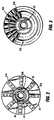
- FIGURE 1 is a schematic illustration of a dual capability combustor for diffusion and premix combustion modes according to the present invention; and
- FIGURES 2 and 3 are cross-sectional views thereof taken generally about on lines 2-2 and 3-3 in Figure 1.
- Referring now to Figure 1, there is provided a combustor, generally designated 10, comprised of a nozzle body including an
inner tube 12 serving as a high pressure liquid fuel nozzle spaced inwardly from and surrounded by acentral tube 14 defining anannular chamber 16 betweentubes outer housing 17 and inner andouter swirlers tube 14 and housing 17 adjacent the tip oftube 14. For reasons discussed hereafter, the inner and outer swirlers are separated by a circumferentially extending continuouscylindrical splitter vane 22. Upstream of the swirler vanes 18 and 20 and between thetube 14 andhousing 17, there is anannular chamber 23 which, at its upstream end, is supplied with air from a suitable source, such as a compressor discharge. Thus, the air flowing throughchamber 23 is split by thevane 22 for flow in part through theinner swirler 18 and in the remaining part, through theouter swirler 20. Note that the outer swirler is axially elongated toward the downstream portion of the nozzle with the splitter vane being coextensive in axial length with theouter swirler 20. - In this embodiment, the inner and outer swirlers are comprised of a plurality of generally radially extending, shaped,
aerodynamic vanes cylindrical vane 22, together with the trailing edges of theinner swirler vanes 24, define a diffusion mixing cup. Also, downstream of the outer swirler vanes 20 andvane 22, thehousing 17 defines apremix cup 28. - Between the
tubes annular chamber 16 which is supplied with gas from asource 29 for flow through avalve 30 and agas supply line 32.Apertures 34 are formed adjacent the tip oftube 12 for flowing the gaseous fuel into the air flowing between thevanes 24 of theinner swirler 18. Additionally, gas fuel may be supplied fromsupply 29 by way ofvalve 30 andsupply line 36 through apremix manifold 38 for flow into a plurality of circumferentially spacedspokes 40.Spokes 40 are located at the upstream portion of thechamber 23 and in the path of the incoming compressor discharge air. Radial or axial apertures or both radial andaxial apertures spokes 40 for supplying fuel from themanifold 38 into thechamber 23 where the fuel and air are mixed. It will be appreciated that thevalve 30 supplies gaseous fuel to one or the other of thesupply lines apertures 34 into the inner swirler for mixing with air in a diffusion combustion mode, or through the apertures in thespokes 40 for mixing with the air inchamber 23 in a premix combustion mode, or the fuel can be supplied to bothapertures 34 and the apertures inspokes 40 simultaneously. - In using the nozzle, the
valve 30 is turned at start-up to supply fuel gas throughsupply line 32,manifold 16 and apertures 34 into the air flowing through theinner swirler 18. It will be appreciated that the air is supplied from the air source by way ofchamber 23 and, hence, only a portion of the air inchamber 23 is supplied theinner swirler 18 for mixing with the fuel gas supplied viaapertures 34. This combined diffusion fuel/air mixture exits thediffusion swirler 18 and enters adiffusion mixing cup 22. The swirling flow induces a recirculation zone along the centerline of the diffusionflame mixing cup 22 which causes hot gas to be drawn back from the combustor reaction zone and anchors the flame front within the diffusionflame mixing cup 22. The portion of the air flowing through theouter swirler 20 is separated from the fuel/air mixture exiting theinner swirler 18 by thesplitter vane 22. Thus, reduced air, i.e., a fraction of the total air suppliedchamber 24, is supplied to theinner swirler 18. This is optimum for the diffusion combustion mode and the flame produces optimum achievable NOx, CO and UHC emissions levels in that mode. - In a premix combustion mode, the
valve 30 is turned to cut off the supply of gas fuel vialine 32 and to supply gas fuel vialine 36 to thespokes 40 and through the apertures into the air in thechamber 23. Thus, the fuel is distributed by thespokes 40 for mixing with the entirety of the air suppliedchamber 23. The fuel/air mixture in the premix combustion mode enters both inner and outer swirlers 18 and 20. The aerodynamic vanes within the inner and outer swirlers accelerate the flow to a high velocity swirl which prevents flashback of combustion from the reaction zone intochamber 23 now serving as the premix chamber. The rotation of the premixed flow exiting the swirlers causes a central recirculation flow of hot gases from the combustion chamber into thepremix cup 28, hence stabilizing the premix flame front within the premix cup. Consequently, it will be appreciated that the entirety of the air flowing into thechamber 23 from the compressor discharge is used for mixing with the fuel exiting the spokes. Thus, a lean fuel/air ratio in the premix mode is obtained, hence reducing the level of NOx emissions at mid to high load operating range of the turbine. - While the invention has been described in connection with what is presently considered to be the most practical and preferred embodiment, it is to be understood that the invention is not to be limited to the disclosed embodiment, but on the contrary, is intended to cover various modifications and equivalent arrangements included within the scope of the appended claims.
Claims (15)
- A nozzle for diffusion and premix modes of combustion in a combustor for a turbine, comprising:
a nozzle body having an axis and defining a chamber about said axis, said chamber having an upstream portion for receiving air from an upstream air source and a downstream portion, including radially spaced, annular inner and outer swirlers about said axis, each swirler having a plurality of shaped aerodynamic vanes for imparting a swirl to air flowing through said chamber and passing through said aerodynamic vanes;
a generally annular vane disposed between said inner and outer swirlers for separating the flow through said swirlers;
a first fuel supply conduit for supplying fuel for mixing substantially solely with the air flowing through said inner swirler, thereby providing a fuel/air mixture for diffusion combustion; and
a second fuel supply conduit for supplying fuel to said chamber upstream of said swirlers for mixing with air in said chamber to form a fuel/air mixture in said chamber for flow thereof through said inner and outer swirlers for premixed combustion. - A nozzle according to Claim 1 wherein said second fuel supply conduit includes a plurality of generally radially extending circumferentially spaced spokes in said chamber, each spoke having at least one aperture for supplying fuel into said chamber.
- A nozzle according to Claim 1 wherein said nozzle body includes a central tube, said inner swirlers being carried by said central tube adjacent an end thereof and extending radially outwardly thereof, said central tube including apertures forming part of said first fuel supply conduit for supplying fuel to said inner swirlers.
- A nozzle according to Claim 1 wherein downstream edges of said inner swirler vanes terminate short of downstream edges of said outer swirler vanes, said annular vane extending downstream of said inner swirler vanes and terminating substantially coextensively with the downstream edges of said outer swirler vanes.
- A nozzle according to Claim 1 including means for supplying fuel to said first and second fuel supply conduits for alternately supplying fuel to said inner swirler and said chamber.
- A nozzle according to Claim 1 including a diffusion flame cup downstream of said inner swirler.
- A nozzle according to Claim 1 including a premix flame cup downstream of said outer swirler.
- A nozzle according to Claim 1 wherein said second fuel supply conduit includes a plurality of generally radially extending circumferentially spaced spokes in said chamber, each spoke having at least one aperture for supplying fuel into said chamber, said nozzle body including a central tube, said inner swirlers being carried by said central tube adjacent an end thereof and extending radially outwardly thereof, said central tube including apertures forming part of said first fuel supply conduit for supplying fuel to said inner swirlers.
- A nozzle according to Claim 8 wherein downstream edges of said inner swirler vanes terminate short of downstream edges of said outer swirler vanes, said annular vane extending downstream of said inner swirler vanes and terminating substantially coextensively with the downstream edges of said outer swirler vanes.
- A nozzle according to Claim 9 including means for supplying fuel to said first and second fuel supply conduits for alternately supplying fuel to said inner swirler and said chamber, a diffusion flame cup downstream of said inner swirler and a premix flame cup downstream of said outer swirler.
- In a method of operating a combustor for a turbine wherein the combustor includes a nozzle body having an axis, a chamber about said axis and inner and outer swirlers adjacent a downstream portion of the chamber, the steps of:
supplying air to the chamber for flow downstream through the swirlers;
separating the air flow through the swirlers into first and second discrete flows through said inner and outer swirlers, respectively;
supplying fuel for mixing substantially solely with the first air flow through the inner swirler to provide a fuel/air mixture for stabilizing diffusion combustion downstream of said swirlers using only a portion of the air supplied to the chamber; and
supplying fuel to said chamber for mixing with the air flow therethrough to form a fuel/air mixture for operation in a premix combustion mode using a totality of the air supplied to the chamber. - A method according to Claim 11 including alternating the supply of fuel to the inner swirler and the chamber to alternate between diffusion and premix combustion modes.
- A method according to Claim 11 wherein the step of supplying fuel for mixing solely with the first air flow includes supplying fuel directly into the inner swirler.
- A method according to Claim 11 wherein the step of supplying fuel to the chamber includes first directing fuel in a radially outwardly direction for mixing with the air flowing axially in said chamber.
- A method according to Claim 11 including alternating the supply of fuel to the inner swirler and the chamber to alternate between diffusion and premix combustion modes, the step of supplying fuel for mixing solely with the first air flow including supplying fuel directly into the inner swirler and the step of supplying fuel to the chamber includes first directing fuel in a radially outwardly direction for mixing with the air flowing axially in said chamber.
Applications Claiming Priority (2)
| Application Number | Priority Date | Filing Date | Title |
|---|---|---|---|
| US08/212,401 US5435126A (en) | 1994-03-14 | 1994-03-14 | Fuel nozzle for a turbine having dual capability for diffusion and premix combustion and methods of operation |
| US212401 | 1994-03-14 |
Publications (3)
| Publication Number | Publication Date |
|---|---|
| EP0672865A2 true EP0672865A2 (en) | 1995-09-20 |
| EP0672865A3 EP0672865A3 (en) | 1997-05-21 |
| EP0672865B1 EP0672865B1 (en) | 2001-10-10 |
Family
ID=22790853
Family Applications (1)
| Application Number | Title | Priority Date | Filing Date |
|---|---|---|---|
| EP95301433A Expired - Lifetime EP0672865B1 (en) | 1994-03-14 | 1995-03-06 | A fuel nozzle for a turbine having dual capability for diffusion and premix combustion and methods of operation |
Country Status (5)
| Country | Link |
|---|---|
| US (1) | US5435126A (en) |
| EP (1) | EP0672865B1 (en) |
| JP (1) | JP3628747B2 (en) |
| CA (1) | CA2143232C (en) |
| DE (1) | DE69523082T2 (en) |
Cited By (3)
| Publication number | Priority date | Publication date | Assignee | Title |
|---|---|---|---|---|
| WO1998028574A2 (en) * | 1996-12-20 | 1998-07-02 | Siemens Aktiengesellschaft | Burner for liquid fuels, method of operating a burner, and swirling element |
| WO2004025183A2 (en) | 2002-09-02 | 2004-03-25 | Siemens Aktiengesellschaft | Burner |
| US8925323B2 (en) | 2012-04-30 | 2015-01-06 | General Electric Company | Fuel/air premixing system for turbine engine |
Families Citing this family (41)
| Publication number | Priority date | Publication date | Assignee | Title |
|---|---|---|---|---|
| US5813232A (en) * | 1995-06-05 | 1998-09-29 | Allison Engine Company, Inc. | Dry low emission combustor for gas turbine engines |
| US5822992A (en) * | 1995-10-19 | 1998-10-20 | General Electric Company | Low emissions combustor premixer |
| EP0925470B1 (en) * | 1996-09-09 | 2000-03-08 | Siemens Aktiengesellschaft | Process and device for burning fuel in air |
| US5816049A (en) * | 1997-01-02 | 1998-10-06 | General Electric Company | Dual fuel mixer for gas turbine combustor |
| US5899075A (en) * | 1997-03-17 | 1999-05-04 | General Electric Company | Turbine engine combustor with fuel-air mixer |
| GB2332509B (en) * | 1997-12-19 | 2002-06-19 | Europ Gas Turbines Ltd | Fuel/air mixing arrangement for combustion apparatus |
| DE19808722C2 (en) * | 1998-03-02 | 2000-03-16 | Siemens Ag | Gas and steam turbine plant and method for operating such a plant |
| JP3457907B2 (en) * | 1998-12-24 | 2003-10-20 | 三菱重工業株式会社 | Dual fuel nozzle |
| JP2002031343A (en) | 2000-07-13 | 2002-01-31 | Mitsubishi Heavy Ind Ltd | Fuel injection member, burner, premixing nozzle of combustor, combustor, gas turbine and jet engine |
| US6467272B1 (en) | 2001-06-25 | 2002-10-22 | Power Systems Mfg, Llc | Means for wear reduction in a gas turbine combustor |
| JP3986348B2 (en) * | 2001-06-29 | 2007-10-03 | 三菱重工業株式会社 | Fuel supply nozzle of gas turbine combustor, gas turbine combustor, and gas turbine |
| JP3970244B2 (en) | 2001-07-10 | 2007-09-05 | 三菱重工業株式会社 | Premixing nozzle and combustor and gas turbine |
| US6655145B2 (en) | 2001-12-20 | 2003-12-02 | Solar Turbings Inc | Fuel nozzle for a gas turbine engine |
| US6915636B2 (en) * | 2002-07-15 | 2005-07-12 | Power Systems Mfg., Llc | Dual fuel fin mixer secondary fuel nozzle |
| US6786047B2 (en) * | 2002-09-17 | 2004-09-07 | Siemens Westinghouse Power Corporation | Flashback resistant pre-mix burner for a gas turbine combustor |
| US6871488B2 (en) * | 2002-12-17 | 2005-03-29 | Pratt & Whitney Canada Corp. | Natural gas fuel nozzle for gas turbine engine |
| EP1507119A1 (en) * | 2003-08-13 | 2005-02-16 | Siemens Aktiengesellschaft | Burner and process to operate a gas turbine |
| US7082765B2 (en) * | 2004-09-01 | 2006-08-01 | General Electric Company | Methods and apparatus for reducing gas turbine engine emissions |
| US20070074518A1 (en) * | 2005-09-30 | 2007-04-05 | Solar Turbines Incorporated | Turbine engine having acoustically tuned fuel nozzle |
| US7703288B2 (en) * | 2005-09-30 | 2010-04-27 | Solar Turbines Inc. | Fuel nozzle having swirler-integrated radial fuel jet |
| US20080078183A1 (en) * | 2006-10-03 | 2008-04-03 | General Electric Company | Liquid fuel enhancement for natural gas swirl stabilized nozzle and method |
| US7966820B2 (en) | 2007-08-15 | 2011-06-28 | General Electric Company | Method and apparatus for combusting fuel within a gas turbine engine |
| US20090056336A1 (en) * | 2007-08-28 | 2009-03-05 | General Electric Company | Gas turbine premixer with radially staged flow passages and method for mixing air and gas in a gas turbine |
| US7908863B2 (en) * | 2008-02-12 | 2011-03-22 | General Electric Company | Fuel nozzle for a gas turbine engine and method for fabricating the same |
| US20090241547A1 (en) * | 2008-03-31 | 2009-10-01 | Andrew Luts | Gas turbine fuel injector for lower heating capacity fuels |
| US7578130B1 (en) * | 2008-05-20 | 2009-08-25 | General Electric Company | Methods and systems for combustion dynamics reduction |
| US8616003B2 (en) | 2008-07-21 | 2013-12-31 | Parker-Hannifin Corporation | Nozzle assembly |
| JP5571197B2 (en) * | 2010-10-28 | 2014-08-13 | 三菱重工業株式会社 | Gas turbine and gas turbine plant equipped with the same |
| RU2456510C1 (en) * | 2011-02-18 | 2012-07-20 | Федеральное государственное унитарное предприятие "Центральный институт авиационного моторостроения имени П.И. Баранова" | Continuous-action combustion chamber |
| CN103134078B (en) * | 2011-11-25 | 2015-03-25 | 中国科学院工程热物理研究所 | Array standing vortex fuel-air premixer |
| JP6154988B2 (en) * | 2012-01-05 | 2017-06-28 | 三菱日立パワーシステムズ株式会社 | Combustor |
| US9395084B2 (en) * | 2012-06-06 | 2016-07-19 | General Electric Company | Fuel pre-mixer with planar and swirler vanes |
| RU2527011C1 (en) * | 2013-05-23 | 2014-08-27 | Федеральное государственное унитарное предприятие "Центральный институт авиационного моторостроения имени П.И. Баранова" | Continuous combustion chamber |
| EP3087323B1 (en) * | 2014-04-03 | 2019-08-21 | Siemens Aktiengesellschaft | Fuel nozzle, burner having such a fuel nozzle, and gas turbine having such a burner |
| EP3198198A1 (en) * | 2014-09-26 | 2017-08-02 | Innecs B.V. | Burner |
| CN104566459B (en) * | 2014-12-08 | 2017-12-12 | 北京华清燃气轮机与煤气化联合循环工程技术有限公司 | A kind of gas-turbine combustion chamber is classified nozzle of air supply |
| CN108731029B (en) | 2017-04-25 | 2021-10-29 | 帕克-汉尼芬公司 | Jet fuel nozzle |
| GB2592267A (en) * | 2020-02-24 | 2021-08-25 | Altair Uk Ltd | Pulse nozzle for filter cleaning systems |
| CN113357671B (en) * | 2020-03-05 | 2022-07-15 | 杭州汽轮动力集团有限公司 | Gas turbine combustor capable of achieving dual-mode conversion of diffusion and premixed combustion |
| CN114738799B (en) * | 2022-04-20 | 2024-03-26 | 新奥能源动力科技(上海)有限公司 | Head assembly of dual-fuel combustion chamber, combustion chamber and gas turbine |
| CN115164231B (en) * | 2022-07-19 | 2023-06-20 | 中国航发沈阳发动机研究所 | Low-emission combustor |
Citations (7)
| Publication number | Priority date | Publication date | Assignee | Title |
|---|---|---|---|---|
| DE3606625A1 (en) * | 1985-03-04 | 1986-09-04 | Kraftwerk Union AG, 4330 Mülheim | Pilot burner with low NOx emission for furnace installations, in particular of gas turbine installations, and method of operating it |
| EP0269824A2 (en) * | 1986-11-25 | 1988-06-08 | General Electric Company | Premixed pilot nozzle for dry low NOx combustor |
| EP0274630A1 (en) * | 1986-12-11 | 1988-07-20 | BBC Brown Boveri AG | Arrangement for a burner |
| US5062792A (en) * | 1987-01-26 | 1991-11-05 | Siemens Aktiengesellschaft | Hybrid burner for a pre-mixing operation with gas and/or oil, in particular for gas turbine systems |
| US5199265A (en) * | 1991-04-03 | 1993-04-06 | General Electric Company | Two stage (premixed/diffusion) gas only secondary fuel nozzle |
| EP0561591A2 (en) * | 1992-03-16 | 1993-09-22 | General Electric Company | Swirler for combustor |
| US5295352A (en) * | 1992-08-04 | 1994-03-22 | General Electric Company | Dual fuel injector with premixing capability for low emissions combustion |
Family Cites Families (4)
| Publication number | Priority date | Publication date | Assignee | Title |
|---|---|---|---|---|
| DE3241162A1 (en) * | 1982-11-08 | 1984-05-10 | Kraftwerk Union AG, 4330 Mülheim | PRE-MIXING BURNER WITH INTEGRATED DIFFUSION BURNER |
| US4982570A (en) * | 1986-11-25 | 1991-01-08 | General Electric Company | Premixed pilot nozzle for dry low Nox combustor |
| US5218824A (en) * | 1992-06-25 | 1993-06-15 | Solar Turbines Incorporated | Low emission combustion nozzle for use with a gas turbine engine |
| US5237812A (en) * | 1992-10-07 | 1993-08-24 | Westinghouse Electric Corp. | Auto-ignition system for premixed gas turbine combustors |
-
1994
- 1994-03-14 US US08/212,401 patent/US5435126A/en not_active Expired - Lifetime
-
1995
- 1995-02-23 CA CA002143232A patent/CA2143232C/en not_active Expired - Fee Related
- 1995-03-06 EP EP95301433A patent/EP0672865B1/en not_active Expired - Lifetime
- 1995-03-06 DE DE69523082T patent/DE69523082T2/en not_active Expired - Fee Related
- 1995-03-07 JP JP04603195A patent/JP3628747B2/en not_active Expired - Fee Related
Patent Citations (7)
| Publication number | Priority date | Publication date | Assignee | Title |
|---|---|---|---|---|
| DE3606625A1 (en) * | 1985-03-04 | 1986-09-04 | Kraftwerk Union AG, 4330 Mülheim | Pilot burner with low NOx emission for furnace installations, in particular of gas turbine installations, and method of operating it |
| EP0269824A2 (en) * | 1986-11-25 | 1988-06-08 | General Electric Company | Premixed pilot nozzle for dry low NOx combustor |
| EP0274630A1 (en) * | 1986-12-11 | 1988-07-20 | BBC Brown Boveri AG | Arrangement for a burner |
| US5062792A (en) * | 1987-01-26 | 1991-11-05 | Siemens Aktiengesellschaft | Hybrid burner for a pre-mixing operation with gas and/or oil, in particular for gas turbine systems |
| US5199265A (en) * | 1991-04-03 | 1993-04-06 | General Electric Company | Two stage (premixed/diffusion) gas only secondary fuel nozzle |
| EP0561591A2 (en) * | 1992-03-16 | 1993-09-22 | General Electric Company | Swirler for combustor |
| US5295352A (en) * | 1992-08-04 | 1994-03-22 | General Electric Company | Dual fuel injector with premixing capability for low emissions combustion |
Cited By (7)
| Publication number | Priority date | Publication date | Assignee | Title |
|---|---|---|---|---|
| WO1998028574A2 (en) * | 1996-12-20 | 1998-07-02 | Siemens Aktiengesellschaft | Burner for liquid fuels, method of operating a burner, and swirling element |
| WO1998028574A3 (en) * | 1996-12-20 | 1998-09-17 | Siemens Ag | Burner for liquid fuels, method of operating a burner, and swirling element |
| US6189320B1 (en) | 1996-12-20 | 2001-02-20 | Siemens Aktiengesellschaft | Burner for fluidic fuels having multiple groups of vortex generating elements |
| WO2004025183A2 (en) | 2002-09-02 | 2004-03-25 | Siemens Aktiengesellschaft | Burner |
| WO2004025183A3 (en) * | 2002-09-02 | 2005-01-20 | Siemens Ag | Burner |
| US7753677B2 (en) | 2002-09-02 | 2010-07-13 | Siemens Aktiengesellschaft | Burner |
| US8925323B2 (en) | 2012-04-30 | 2015-01-06 | General Electric Company | Fuel/air premixing system for turbine engine |
Also Published As
| Publication number | Publication date |
|---|---|
| JP3628747B2 (en) | 2005-03-16 |
| JPH0821627A (en) | 1996-01-23 |
| CA2143232A1 (en) | 1995-09-15 |
| US5435126A (en) | 1995-07-25 |
| EP0672865A3 (en) | 1997-05-21 |
| CA2143232C (en) | 2008-12-09 |
| EP0672865B1 (en) | 2001-10-10 |
| DE69523082D1 (en) | 2001-11-15 |
| DE69523082T2 (en) | 2002-06-06 |
Similar Documents
| Publication | Publication Date | Title |
|---|---|---|
| US5435126A (en) | Fuel nozzle for a turbine having dual capability for diffusion and premix combustion and methods of operation | |
| US5295352A (en) | Dual fuel injector with premixing capability for low emissions combustion | |
| US6092363A (en) | Low Nox combustor having dual fuel injection system | |
| EP1193449B1 (en) | Multiple annular swirler | |
| EP0878665B1 (en) | Low emissions combustion system for a gas turbine engine | |
| US6609376B2 (en) | Device in a burner for gas turbines | |
| EP0620402B1 (en) | Premix combustor with concentric annular passages | |
| EP1193448B1 (en) | Multiple annular combustion chamber swirler having atomizing pilot | |
| EP1216385B1 (en) | Variable premix-lean burn combustor | |
| JP3077763B2 (en) | Gas turbine combustion chamber | |
| US6530222B2 (en) | Swirled diffusion dump combustor | |
| US20090056336A1 (en) | Gas turbine premixer with radially staged flow passages and method for mixing air and gas in a gas turbine | |
| US6837052B2 (en) | Advanced fuel nozzle design with improved premixing | |
| US20040083737A1 (en) | Airflow modulation technique for low emissions combustors | |
| JP2001510885A (en) | Burner device for combustion equipment, especially for gas turbine combustors | |
| KR100679596B1 (en) | Radial inflow dual fuel injector | |
| US20040118119A1 (en) | Fully premixed pilotless secondary fuel nozzle | |
| GB2320755A (en) | Dual fuel gas turbine | |
| JPH09250714A (en) | Gas combustion device |
Legal Events
| Date | Code | Title | Description |
|---|---|---|---|
| PUAI | Public reference made under article 153(3) epc to a published international application that has entered the european phase |
Free format text: ORIGINAL CODE: 0009012 |
|
| AK | Designated contracting states |
Kind code of ref document: A2 Designated state(s): CH DE FR GB IT LI |
|
| PUAL | Search report despatched |
Free format text: ORIGINAL CODE: 0009013 |
|
| AK | Designated contracting states |
Kind code of ref document: A3 Designated state(s): CH DE FR GB IT LI |
|
| 17P | Request for examination filed |
Effective date: 19971121 |
|
| 17Q | First examination report despatched |
Effective date: 19990427 |
|
| GRAG | Despatch of communication of intention to grant |
Free format text: ORIGINAL CODE: EPIDOS AGRA |
|
| GRAG | Despatch of communication of intention to grant |
Free format text: ORIGINAL CODE: EPIDOS AGRA |
|
| GRAG | Despatch of communication of intention to grant |
Free format text: ORIGINAL CODE: EPIDOS AGRA |
|
| GRAH | Despatch of communication of intention to grant a patent |
Free format text: ORIGINAL CODE: EPIDOS IGRA |
|
| GRAH | Despatch of communication of intention to grant a patent |
Free format text: ORIGINAL CODE: EPIDOS IGRA |
|
| GRAA | (expected) grant |
Free format text: ORIGINAL CODE: 0009210 |
|
| AK | Designated contracting states |
Kind code of ref document: B1 Designated state(s): CH DE FR GB IT LI |
|
| REG | Reference to a national code |
Ref country code: CH Ref legal event code: NV Representative=s name: RITSCHER & SEIFERT Ref country code: CH Ref legal event code: EP |
|
| REF | Corresponds to: |
Ref document number: 69523082 Country of ref document: DE Date of ref document: 20011115 |
|
| ET | Fr: translation filed | ||
| REG | Reference to a national code |
Ref country code: GB Ref legal event code: IF02 |
|
| PLBE | No opposition filed within time limit |
Free format text: ORIGINAL CODE: 0009261 |
|
| STAA | Information on the status of an ep patent application or granted ep patent |
Free format text: STATUS: NO OPPOSITION FILED WITHIN TIME LIMIT |
|
| 26N | No opposition filed | ||
| PGFP | Annual fee paid to national office [announced via postgrant information from national office to epo] |
Ref country code: CH Payment date: 20080328 Year of fee payment: 14 |
|
| PGFP | Annual fee paid to national office [announced via postgrant information from national office to epo] |
Ref country code: GB Payment date: 20080327 Year of fee payment: 14 |
|
| PGFP | Annual fee paid to national office [announced via postgrant information from national office to epo] |
Ref country code: FR Payment date: 20080317 Year of fee payment: 14 Ref country code: DE Payment date: 20080430 Year of fee payment: 14 |
|
| PGFP | Annual fee paid to national office [announced via postgrant information from national office to epo] |
Ref country code: IT Payment date: 20080328 Year of fee payment: 14 |
|
| REG | Reference to a national code |
Ref country code: CH Ref legal event code: PL |
|
| GBPC | Gb: european patent ceased through non-payment of renewal fee |
Effective date: 20090306 |
|
| REG | Reference to a national code |
Ref country code: FR Ref legal event code: ST Effective date: 20091130 |
|
| PG25 | Lapsed in a contracting state [announced via postgrant information from national office to epo] |
Ref country code: LI Free format text: LAPSE BECAUSE OF NON-PAYMENT OF DUE FEES Effective date: 20090331 Ref country code: DE Free format text: LAPSE BECAUSE OF NON-PAYMENT OF DUE FEES Effective date: 20091001 Ref country code: CH Free format text: LAPSE BECAUSE OF NON-PAYMENT OF DUE FEES Effective date: 20090331 |
|
| PG25 | Lapsed in a contracting state [announced via postgrant information from national office to epo] |
Ref country code: GB Free format text: LAPSE BECAUSE OF NON-PAYMENT OF DUE FEES Effective date: 20090306 Ref country code: FR Free format text: LAPSE BECAUSE OF NON-PAYMENT OF DUE FEES Effective date: 20091123 |
|
| PG25 | Lapsed in a contracting state [announced via postgrant information from national office to epo] |
Ref country code: IT Free format text: LAPSE BECAUSE OF NON-PAYMENT OF DUE FEES Effective date: 20090306 |