EP0672818B1 - Modular measurement while drilling sensor assembly - Google Patents
Modular measurement while drilling sensor assembly Download PDFInfo
- Publication number
- EP0672818B1 EP0672818B1 EP95301676A EP95301676A EP0672818B1 EP 0672818 B1 EP0672818 B1 EP 0672818B1 EP 95301676 A EP95301676 A EP 95301676A EP 95301676 A EP95301676 A EP 95301676A EP 0672818 B1 EP0672818 B1 EP 0672818B1
- Authority
- EP
- European Patent Office
- Prior art keywords
- assembly
- housing
- shaft
- sensor
- motor
- Prior art date
- Legal status (The legal status is an assumption and is not a legal conclusion. Google has not performed a legal analysis and makes no representation as to the accuracy of the status listed.)
- Expired - Lifetime
Links
- 238000005553 drilling Methods 0.000 title claims description 32
- 238000005259 measurement Methods 0.000 title description 10
- 230000015572 biosynthetic process Effects 0.000 claims description 15
- 238000011156 evaluation Methods 0.000 claims description 5
- 238000004891 communication Methods 0.000 claims description 4
- 230000008878 coupling Effects 0.000 description 21
- 238000010168 coupling process Methods 0.000 description 21
- 238000005859 coupling reaction Methods 0.000 description 21
- 230000000712 assembly Effects 0.000 description 5
- 238000000429 assembly Methods 0.000 description 5
- 238000000034 method Methods 0.000 description 5
- 230000008901 benefit Effects 0.000 description 4
- 238000006073 displacement reaction Methods 0.000 description 4
- XQCFHQBGMWUEMY-ZPUQHVIOSA-N Nitrovin Chemical compound C=1C=C([N+]([O-])=O)OC=1\C=C\C(=NNC(=N)N)\C=C\C1=CC=C([N+]([O-])=O)O1 XQCFHQBGMWUEMY-ZPUQHVIOSA-N 0.000 description 3
- 239000000463 material Substances 0.000 description 3
- 230000008859 change Effects 0.000 description 2
- 238000013500 data storage Methods 0.000 description 2
- 230000033001 locomotion Effects 0.000 description 2
- 238000012423 maintenance Methods 0.000 description 2
- 230000013011 mating Effects 0.000 description 2
- 230000007246 mechanism Effects 0.000 description 2
- XLYOFNOQVPJJNP-UHFFFAOYSA-N water Substances O XLYOFNOQVPJJNP-UHFFFAOYSA-N 0.000 description 2
- UFHFLCQGNIYNRP-UHFFFAOYSA-N Hydrogen Chemical compound [H][H] UFHFLCQGNIYNRP-UHFFFAOYSA-N 0.000 description 1
- 230000005540 biological transmission Effects 0.000 description 1
- 230000007812 deficiency Effects 0.000 description 1
- 230000001419 dependent effect Effects 0.000 description 1
- 230000009977 dual effect Effects 0.000 description 1
- 239000012530 fluid Substances 0.000 description 1
- 230000005251 gamma ray Effects 0.000 description 1
- 229910052739 hydrogen Inorganic materials 0.000 description 1
- 239000001257 hydrogen Substances 0.000 description 1
- 238000012986 modification Methods 0.000 description 1
- 230000004048 modification Effects 0.000 description 1
- 230000000644 propagated effect Effects 0.000 description 1
- 239000002994 raw material Substances 0.000 description 1
- 238000011084 recovery Methods 0.000 description 1
- 238000001228 spectrum Methods 0.000 description 1
- 230000006641 stabilisation Effects 0.000 description 1
- 238000011105 stabilization Methods 0.000 description 1
- 238000012546 transfer Methods 0.000 description 1
Images


Classifications
-
- E—FIXED CONSTRUCTIONS
- E21—EARTH DRILLING; MINING
- E21B—EARTH DRILLING, e.g. DEEP DRILLING; OBTAINING OIL, GAS, WATER, SOLUBLE OR MELTABLE MATERIALS OR A SLURRY OF MINERALS FROM WELLS
- E21B17/00—Drilling rods or pipes; Flexible drill strings; Kellies; Drill collars; Sucker rods; Cables; Casings; Tubings
- E21B17/02—Couplings; joints
- E21B17/04—Couplings; joints between rod or the like and bit or between rod and rod or the like
- E21B17/042—Threaded
-
- E—FIXED CONSTRUCTIONS
- E21—EARTH DRILLING; MINING
- E21B—EARTH DRILLING, e.g. DEEP DRILLING; OBTAINING OIL, GAS, WATER, SOLUBLE OR MELTABLE MATERIALS OR A SLURRY OF MINERALS FROM WELLS
- E21B4/00—Drives for drilling, used in the borehole
- E21B4/02—Fluid rotary type drives
-
- E—FIXED CONSTRUCTIONS
- E21—EARTH DRILLING; MINING
- E21B—EARTH DRILLING, e.g. DEEP DRILLING; OBTAINING OIL, GAS, WATER, SOLUBLE OR MELTABLE MATERIALS OR A SLURRY OF MINERALS FROM WELLS
- E21B44/00—Automatic control systems specially adapted for drilling operations, i.e. self-operating systems which function to carry out or modify a drilling operation without intervention of a human operator, e.g. computer-controlled drilling systems; Systems specially adapted for monitoring a plurality of drilling variables or conditions
- E21B44/005—Below-ground automatic control systems
-
- E—FIXED CONSTRUCTIONS
- E21—EARTH DRILLING; MINING
- E21B—EARTH DRILLING, e.g. DEEP DRILLING; OBTAINING OIL, GAS, WATER, SOLUBLE OR MELTABLE MATERIALS OR A SLURRY OF MINERALS FROM WELLS
- E21B47/00—Survey of boreholes or wells
- E21B47/01—Devices for supporting measuring instruments on drill bits, pipes, rods or wirelines; Protecting measuring instruments in boreholes against heat, shock, pressure or the like
- E21B47/017—Protecting measuring instruments
-
- E—FIXED CONSTRUCTIONS
- E21—EARTH DRILLING; MINING
- E21B—EARTH DRILLING, e.g. DEEP DRILLING; OBTAINING OIL, GAS, WATER, SOLUBLE OR MELTABLE MATERIALS OR A SLURRY OF MINERALS FROM WELLS
- E21B47/00—Survey of boreholes or wells
- E21B47/06—Measuring temperature or pressure
-
- E—FIXED CONSTRUCTIONS
- E21—EARTH DRILLING; MINING
- E21B—EARTH DRILLING, e.g. DEEP DRILLING; OBTAINING OIL, GAS, WATER, SOLUBLE OR MELTABLE MATERIALS OR A SLURRY OF MINERALS FROM WELLS
- E21B47/00—Survey of boreholes or wells
- E21B47/12—Means for transmitting measuring-signals or control signals from the well to the surface, or from the surface to the well, e.g. for logging while drilling
-
- E—FIXED CONSTRUCTIONS
- E21—EARTH DRILLING; MINING
- E21B—EARTH DRILLING, e.g. DEEP DRILLING; OBTAINING OIL, GAS, WATER, SOLUBLE OR MELTABLE MATERIALS OR A SLURRY OF MINERALS FROM WELLS
- E21B7/00—Special methods or apparatus for drilling
- E21B7/04—Directional drilling
- E21B7/06—Deflecting the direction of boreholes
- E21B7/068—Deflecting the direction of boreholes drilled by a down-hole drilling motor
-
- F—MECHANICAL ENGINEERING; LIGHTING; HEATING; WEAPONS; BLASTING
- F01—MACHINES OR ENGINES IN GENERAL; ENGINE PLANTS IN GENERAL; STEAM ENGINES
- F01C—ROTARY-PISTON OR OSCILLATING-PISTON MACHINES OR ENGINES
- F01C1/00—Rotary-piston machines or engines
- F01C1/08—Rotary-piston machines or engines of intermeshing engagement type, i.e. with engagement of co- operating members similar to that of toothed gearing
- F01C1/10—Rotary-piston machines or engines of intermeshing engagement type, i.e. with engagement of co- operating members similar to that of toothed gearing of internal-axis type with the outer member having more teeth or tooth-equivalents, e.g. rollers, than the inner member
- F01C1/107—Rotary-piston machines or engines of intermeshing engagement type, i.e. with engagement of co- operating members similar to that of toothed gearing of internal-axis type with the outer member having more teeth or tooth-equivalents, e.g. rollers, than the inner member with helical teeth
Definitions
- the present invention relates to a measurement while drilling sensor assembly which is particularly suitable for use with a downhole drilling device.
- Downhole drilling devices of the positive displacement type are well known.
- US-A-5135059 discloses a downhole drill which includes a housing, a stator having a helically contoured inner surface secured within the housing and a rotor having a helically contoured exterior surface disposed within the stator.
- Drilling fluid e.g., drilling mud
- a drive sleigh is connected to the rotor via a flexible coupling to compensate for eccentric movement of the rotor.
- Other examples of downhole drilling devices are disclosed in US-A-4729675, 4982801 and 5074681.
- Formation evaluation tools assist operators in identifying the particular geological material through which a drill is passing. This feedback of information is used by operators to direct the drilling of a well, through, in the case of a horizontal well, a desired layer or stratum without deviating therefrom. These tools have employed several techniques in the past which have been used independently and/or in some combination thereof. Formation resistivity, density and porosity logging are three well known techniques. US-A-5001675 describes one resistivity measuring device, having a dual propagation resistivity (DPR) device having one or more pairs of transmitting antennae spaced from one or more pairs of receiving antennae. Magnetic dipoles are employed which operate in the mf and lower hf spectrum.
- DPR dual propagation resistivity
- an electromagnetic wave is propagated from the transmitting antenna into the formation surrounding the borehole and is detected as it passes by the two receiving antennas.
- the phase and the amplitude are measured in a first or far receiving antenna which is compared to the phase and amplitude received in a second or near receiving antenna. Resistivities are derived from the phase differences and the amplitude ratio of the receiving signals.
- the formation evaluation of DPR tool communicates the resistivity data and then transmits this information to the drilling operator using mud pulse telemetry.
- Other examples of DPR units are disclosed in US-A-4786874, 4575681 and 4570123.
- Formation density logging devices such as that described in US-A-5134285, typically employ a gamma ray source and a detector.
- gamma rays are emitted from the source, enter the formation to be studied, and interact with the atomic elections of the material of the formation and the attenuation thereof is measured by the detector and from this the density of the formation is determined.
- a formation porosity measurement device such as that described in US-A-5144126, include a neutron emission source and a detector. In use, high energy neutrons are emitted into the surrounding formation and the detectors measure neutron energy depletion due to the presence of hydrogen in the formation.
- Other examples of nuclear logging devices are disclosed in US-A-5126564 and 5083124.
- the drill bit is typically steered through the pay zone by alternately rotating and sliding the drill string assembly and bit into a different direction.
- the distance between the DPR sensor and the bit requires the wellbore to be drilled at a minimal angle with respect to the longitudinal direction of the pay-zone, otherwise the drill bit may enter a different zone long before the DPR sensor would recognize that fact. In the situation where the adjacent zone includes water, a potential problem becomes more readily apparent.
- a typical cross-over assembly for mating with a measurement while drilling (MWD) tool (e.g., a mud pulse telemetry) is connected to a typical positive displacement mud motor (e.g., a Moineau motor).
- the motor comprises a housing with a stator having a helically contoured inner surface and a rotor having a cooperating helically contoured outer surface.
- a modular sensor assembly comprises two portions, an upper drive shaft portion which includes a flexible shaft connected to the motor and a lower sensor portion. It is preferred that all shaft connections be a spline connection, as is known.
- the lower end of the flexible shaft is connected to a hollowed shaft which extend beyond the lower end of the upper drive shaft portion and is supported by a radial bearing.
- the lower sensor portion has a central channel extending longitudinally therethrough, with the lower portion of the hollowed shaft extending through this channel.
- the sensor portion may comprises any type of MWD sensor, however the present invention is preferably use with sensors (e.g., Formation evaluation sensors) that benefit from obtaining measurements close to the bit.
- the MWD sensors were disposed above the motor (when a motor is employed, e.g., directional drilling) which results in the sensor being located further from the bit.
- Communication between the sensor portion and the other MWD devices e.g., a mud pulse telemetry device (or any other data storage or other telemetry type device) is accomplished by means of a conductive wire disposed within a channel which extends through the cross-over assembly, the motor assembly and the upper drive shaft assembly.
- the conductive wire terminates at each end with a known type electrical connector built into the corresponding assembly.
- the lower end of the hollowed shaft is supported with a radial bearing and connected to a flexible shaft of an adjustable kick off assembly connected to the sensor portion.
- the adjustable kick off assembly allows the introduction of a kick off angle, generally between 0 and 30 degrees, in the assembly. This is a well known method of direction drilling or steering of the drill bit.
- the adjustable kick off assembly is connected to a typical bearing pack assembly.
- the lower end of the bearing pack assembly is typically connected to a drive shaft, a bit box and then the bit.
- a cross-over adjustable kick off assembly is used in place of the above described adjustable kick off assembly to provide a direct connection between the motor and the adjustable kick off assembly. This direct connection is desired when drilling operations do not require the aforementioned sensor assembly of the present invention.
- the modular capability of the sensor and drilling motor assemblies is an important feature of the present invention.
- MWD tools and drilling motors have significantly different maintenance cycles, costs, and failure mechanisms.
- the MWD tool i.e., the sensor assembly
- equipment utilization levels are maximized by allowing for rigsite replacement of worn/damaged modular tool assemblies. Therefore, by utilizing the useful life of the MWD tool and the drilling motor substantial cost savings are realized over integrated systems. For these reasons the modular concept of the present invention is believed to provide significant benefits over the integral sensor and motor assembly disclosed in EP-A-624706.
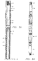
- 1A-D are a cross sectional side elevation view of a mud motor assembly with a modular measurement while drilling sensor assembly.
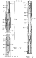
- Figures 2A-B are views of the modular sensor in Figures 1A-D wherein Figure 2A is a partly cross sectional side elevation view thereof and Figure 2B is an end view thereof, and
- Figure 3 is a cross section side elevation view of a cross-over adjustable kick off assembly for use with the mud motor of Figures 1A-D.
- a cross-over assembly 10 has a rotary coupling 12 for mating with a measurement while drilling (MWD) tool (e.g., a mud pulse telemetry, not shown) at one end and a rotary coupling 14 at the other end, with a mud flow channel 16 extending longitudinally through about the centre of cross-over assembly 10.
- MWD measurement while drilling
- a positive displacement mud motor e.g., a Moineau motor, the positive displacement motor described in US-A-5135059, or any other suitable motor
- rotary coupling 14 of cross-over assembly 10 is connected to a rotary coupling 20 of motor 18.
- Motor 18 comprises a housing 22, a stator 24 and a rotor 26.
- Stator 24 has a helically contoured inner surface and rotor 26 has a cooperating helically contoured outer surface, as is clearly shown in the Figures and is known.
- a modular sensor assembly 28 comprises two portions, an upper drive shaft portion 30 which includes a flexible shaft connection and a lower sensor housing portion 32 (Figure 2A).
- Modular sensor assembly 28 is connected at one end thereof to motor 18. More specifically, a rotary coupling 34 of motor 18 is connected to a rotary coupling 36 of portion 30.
- a channel 38 is provided at the lower or downhole end of motor 18 to direct the flow of mud to a channel 40 of portion 30.
- Portion 30 comprises an outer housing 42 with channel 40 extending longitudinally therethrough.
- a flexible shaft 44 is connected at the upper end thereof to a coupling 45 attached at the lower end of rotor 26 for rotating therewith. It is preferred that the connection of shaft 44 and rotor 26 be a splined connection, as is known.
- shaft 44 The lower end of shaft 44 is connected to a coupling 45 at the upper end of a hollowed shaft 47 for rotation therewith.
- Shaft 47 has upper and lower vent holes 48, 50 respectively, to allow drilling mud to flow from channel 40 through a channel 46 in shaft 47.
- Shaft 47 extends beyond the lower end of housing 42.
- Sensor housing portion 32 has a central channel 52 longitudinally therethrough, with the lower portion of shaft 47 extending through channel 52.
- Portion 32 has an outer housing 54 the upper end of which is connected to the lower end of housing 42. More specifically, a rotary coupling 58 of housing 42 is connected to a rotary coupling 60 of housing 54.
- Hollow shaft 17 is required to transfer the rotational forces downhole and to provide a path (i.e. 1 channel 46) for the flow of drilling mud.
- Sensor portion 32 may comprise any type of MWD sensor, although it is preferable to use sensors that benefit from obtaining measurements close to the bit, as it is readily apparent that the MWD sensor is much closer to the bit than the prior art.
- the MWD sensors were disposed above the motor (when a motor is employed, e.g., directional drilling) which results in the sensor being located further from the bit.
- Communication between sensor portion 32 and the aforementioned MWD devices, i.e., the mud pulse telemetry device (or any other data storage or other telemetry type device) is accomplished by means of a conductive wire disposed within a channel 61 which originates in the housing of cross-over assembly 10 and continues discretely through housings 22 and 42.
- the conductive wire terminates at each end with a known type electrical connector built into the corresponding housing. It will be appreciated that communication may be accomplished by way of electromagnetic wave transmission, such as is described in US-A-5160925, or in any other suitable manner.
- shaft 47 is connected by a coupling 45 to a flexible shaft 62 for rotation therewith.
- Shaft 62 is disposed within a housing 64 of an adjustable kick off assembly 65 which is connected at its upper end to the lower end of portion 32. More specifically, a rotary coupling 66 of housing 54 is connected to a rotary coupling 68 of housing 64.
- Housing 64 is an adjustable kick off housing, which allows the introduction of a kick off angle, generally between 0 and 3 degrees, in the assembly. This is a well known method of direction drilling or steering of the drill bit.
- Shaft 62 is connected to a shaft 70 of a bearing pack assembly 72.
- Bearing pack assembly has an outer housing 74 which is connected at its upper end to the lower end of housing 64 by rotary couplings 76 and 78 respectively. As mentioned hereinabove, it is preferred that all shaft interconnections (including couplings) comprise connections.
- the lower end of bearing pack assembly 72 is typically connected to a drive shaft housing 75 with a bit box 76 and then the bit (which is not shown but is well known in the art).
- cross-over assembly 10, motor 18 and bearing pack assembly 72 are all well known devices in the art.
- the adjustable kick off assembly 65 is also a well known device in the art, however it has been modified at its upper end to accept sensor assembly by extending the upper portion of housing 64, as is clearly shown in Figure 1C. Due to this modification, the adjustable kick off assembly cannot be directly connected to motor 18, as in the prior art. Accordingly, a cross-over adjustable kick off assembly of the type shown in Figure 3 and described hereinafter is used in place of the above described adjustable kick off assembly 65 to provide a direct connection between the motor and the adjustable kick off assembly. This direct connection is desired when drilling operations do not require the aforementioned sensor assembly.
- MWD tools and drilling motors have significantly different maintenance cycles, costs, and failure mechanisms.
- the MWD tool i.e., the sensor assembly
- equipment utilization levels are maximized by allowing for rigsite replacement of worn/damaged modular tool assemblies. Therefore, by utilizing the useful life of the MWD tool and the drilling motor substantial cost savings are realized over integrated systems. For these reasons the modular concept described above is believed to provide significant benefits over the integral sensor and motor assembly disclosed in EP-A-624706.
- sensor housing portion 32 comprises housing 54 having rotary couplings 60 and 66 at each end thereof with channel 52 extending longitudinally therethrough.
- Channel 52 must be of a diameter sufficient for accepting shaft 47 therein and to allow for rotation of shaft 47.
- portion 32 is an electromagnetic resistivity tool of a type well known in the art (e.g., the aforementioned DPR tool).
- MWD tool formation evaluation tool
- the aforementioned cross-over adjustable kick off assembly for use with the above described motor assembly when the sensor is not employed is shown generally at 80.
- Assembly 80 replaces assemblies 28 and 65.
- Assembly 80 is shown in Figure 3 connected between motor 18 and bearing pack assembly 72. Accordingly, rotary coupling 34 of motor 18 is connected to a rotary coupling 68' of assembly 80.
- a flexible shaft 62 is connected at the upper end thereof to a coupling 45 attached at the lower end of rotor 26 for rotating therewith. It is preferred that the connection of shaft 44 and rotor 26 be a splined connection, as is known.
- Shaft 62 is disposed within a housing 64' of cross-over adjustable kick off assembly 80 which is connected at its lower end to the upper end of bearing pack assembly 72.
- the adjustable kick off assembly allows the introduction of a kick off angle, generally between 0 and 3 degrees, in the assembly. Again, this is a well known method of direction drilling or steering of the drill bit.
- Shaft 62 is connected to shaft 70 of bearing pack assembly 72.
- all shaft interconnections (including couplings) described herein comprise splined shaft connections.
Description
Claims (11)
- A down hole assembly including:
a mud motor (18) comprising:a modular sensor assembly (28) comprising:(a) a motor housing (22) having first and second opposed ends,(b) a stator (24) disposed in said motor housing (22), and(c) a rotor (26) disposed in said motor housing (22) for cooperating with said stator (24) to generate rotary forces;a bearing housing (74) having an axial opening therethrough, said bearing housing (74) having first and second opposed ends;(a) a sensor housing (32) having an axial opening therethrough, said sensor housing (32) having first and second opposed ends, and(b) a sensor disposed in said sensor housing (32); a bearing pack (72) comprising:
characterised in that:(i) the first end of the sensor housing (32) is removably connected to the second end of the motor housing (22);(ii) the modular sensor assembly (28) further comprises a first shaft (44) supported within the axial opening of the sensor housing (32), said first shaft (44) having first and second opposed ends, the first end of the first shaft (44) being removably connected to the rotor (26);(iii) the first end of the bearing housing (74) is removably connected (76,78) to the second end of the sensor housing (32); and(iv) the bearing pack (72) further comprises a second shaft (47) supported within said axial opening of the bearing housing (74), the second shaft (47) having first and second opposed ends, said first end of said second shaft (47) being removably connected to said second end of the first shaft (44), and said second end of the second shaft (47) being for communicating rotary forces to a drill bit. - An assembly as claimed in claim 1 further comprising a channel extending through said motor housing (22) to said sensor housing (32).
- An assembly as claimed in claim 1 or claim 2 further comprising adjustable kick off means (80) having a housing with a first end thereof removably connected to said second end of said sensor housing (32) and a second end thereof connected to said first end of said bearing housing (74), said adjustable kick off means (80) being for introducing a kick off angle in said down hole assembly.
- An assembly as claimed in claim 3 wherein said kick off angle is between 0 and 3 degrees.
- An assembly as claimed in any one of claims 1 to 4 wherein said first end of said first shaft (44) is removably connected to said rotor (26) by a flexible interconnection.
- An assembly as claimed in any one of claims 1 to 5 wherein said stator (24) comprises a helically grooved inner surface; and said rotor (26) comprises a grooved outer surface adapted to rotate about the inside surface of said stator (24) in response to a flow of drilling mud therethrough.
- An assembly as claimed in any one of claims 1 to 6 further comprising means for communicating with a tool located up hole of the mud motor.
- An assembly as claimed in claim 7 wherein said means for communicating comprises a wire connecting said sensor to the tool located up hole of the mud motor (18).
- An assembly as claimed in claim 7 wherein said means for communicating comprises means for electromagnetic telemetry communication with the tool located up hole of the mud motor (18).
- An assembly as claimed in any one of claims 1 to 9 wherein said sensor comprises a formation evaluation sensor.
- An assembly as claimed in any one of claims 1 to 10, further comprising a shaft housing (62,70), said shaft housing (62,70) having first and second opposed ends and an axial opening therethrough, and the assembly being modified in that said first end of said shaft housing (62,70) is connected to said second end of said sensor housing (32), and said first end of said bearing housing (74) is connected to said second end of said shaft housing (62,70).
Applications Claiming Priority (2)
| Application Number | Priority Date | Filing Date | Title |
|---|---|---|---|
| US08/212,230 US5456106A (en) | 1993-05-12 | 1994-03-14 | Modular measurement while drilling sensor assembly |
| US212230 | 1994-03-14 |
Publications (2)
| Publication Number | Publication Date |
|---|---|
| EP0672818A1 EP0672818A1 (en) | 1995-09-20 |
| EP0672818B1 true EP0672818B1 (en) | 2000-02-02 |
Family
ID=22790129
Family Applications (1)
| Application Number | Title | Priority Date | Filing Date |
|---|---|---|---|
| EP95301676A Expired - Lifetime EP0672818B1 (en) | 1994-03-14 | 1995-03-14 | Modular measurement while drilling sensor assembly |
Country Status (4)
| Country | Link |
|---|---|
| US (1) | US5456106A (en) |
| EP (1) | EP0672818B1 (en) |
| CA (1) | CA2144497C (en) |
| NO (1) | NO311271B1 (en) |
Families Citing this family (16)
| Publication number | Priority date | Publication date | Assignee | Title |
|---|---|---|---|---|
| US5679894A (en) * | 1993-05-12 | 1997-10-21 | Baker Hughes Incorporated | Apparatus and method for drilling boreholes |
| US5720354A (en) * | 1996-01-11 | 1998-02-24 | Vermeer Manufacturing Company | Trenchless underground boring system with boring tool location |
| US5725061A (en) * | 1996-05-24 | 1998-03-10 | Applied Technologies Associates, Inc. | Downhole drill bit drive motor assembly with an integral bilateral signal and power conduction path |
| US5817937A (en) * | 1997-03-25 | 1998-10-06 | Bico Drilling Tools, Inc. | Combination drill motor with measurement-while-drilling electronic sensor assembly |
| US6349778B1 (en) | 2000-01-04 | 2002-02-26 | Performance Boring Technologies, Inc. | Integrated transmitter surveying while boring entrenching powering device for the continuation of a guided bore hole |
| US9745799B2 (en) | 2001-08-19 | 2017-08-29 | Smart Drilling And Completion, Inc. | Mud motor assembly |
| US9051781B2 (en) | 2009-08-13 | 2015-06-09 | Smart Drilling And Completion, Inc. | Mud motor assembly |
| US6698536B2 (en) | 2001-10-01 | 2004-03-02 | Smith International, Inc. | Roller cone drill bit having lubrication contamination detector and lubrication positive pressure maintenance system |
| WO2005064114A1 (en) * | 2003-12-19 | 2005-07-14 | Baker Hughes Incorporated | Method and apparatus for enhancing directional accuracy and control using bottomhole assembly bending measurements |
| US7518528B2 (en) * | 2005-02-28 | 2009-04-14 | Scientific Drilling International, Inc. | Electric field communication for short range data transmission in a borehole |
| CA2544457C (en) | 2006-04-21 | 2009-07-07 | Mostar Directional Technologies Inc. | System and method for downhole telemetry |
| US7530273B1 (en) | 2006-07-12 | 2009-05-12 | John A. Conklin | Modular fiber optic sensor |
| US20080034856A1 (en) * | 2006-08-08 | 2008-02-14 | Scientific Drilling International | Reduced-length measure while drilling apparatus using electric field short range data transmission |
| US8069716B2 (en) * | 2007-06-21 | 2011-12-06 | Scientific Drilling International, Inc. | Multi-coupling reduced length measure while drilling apparatus |
| CN103835664B (en) * | 2014-02-28 | 2015-11-04 | 中国地质大学(武汉) | A kind of drilling rod launching dipole drill string for electromagnetic wave while-drilling wireless measurement signal |
| US10364666B2 (en) | 2017-05-09 | 2019-07-30 | Nabors Drilling Technologies Usa, Inc. | Optimized directional drilling using MWD data |
Family Cites Families (13)
| Publication number | Priority date | Publication date | Assignee | Title |
|---|---|---|---|---|
| US4578675A (en) * | 1982-09-30 | 1986-03-25 | Macleod Laboratories, Inc. | Apparatus and method for logging wells while drilling |
| US4492276A (en) * | 1982-11-17 | 1985-01-08 | Shell Oil Company | Down-hole drilling motor and method for directional drilling of boreholes |
| FR2562601B2 (en) * | 1983-05-06 | 1988-05-27 | Geoservices | DEVICE FOR TRANSMITTING SIGNALS OF A TRANSMITTER LOCATED AT LARGE DEPTH |
| US4697651A (en) * | 1986-12-22 | 1987-10-06 | Mobil Oil Corporation | Method of drilling deviated wellbores |
| US4852399A (en) * | 1988-07-13 | 1989-08-01 | Anadrill, Inc. | Method for determining drilling conditions while drilling |
| US4901804A (en) * | 1988-08-15 | 1990-02-20 | Eastman Christensen Company | Articulated downhole surveying instrument assembly |
| US5064006A (en) * | 1988-10-28 | 1991-11-12 | Magrange, Inc | Downhole combination tool |
| US4982801A (en) * | 1989-01-04 | 1991-01-08 | Teleco Oilfield Services Inc. | Flexible coupling for downhole motor |
| CA2024061C (en) * | 1990-08-27 | 2001-10-02 | Laurier Emile Comeau | System for drilling deviated boreholes |
| US5135059A (en) * | 1990-11-19 | 1992-08-04 | Teleco Oilfield Services, Inc. | Borehole drilling motor with flexible shaft coupling |
| WO1992018882A1 (en) * | 1991-04-17 | 1992-10-29 | Smith International, Inc. | Short hop communication link for downhole mwd system |
| US5320179A (en) * | 1992-08-06 | 1994-06-14 | Slimdril International Inc. | Steering sub for flexible drilling |
| US5325714A (en) * | 1993-05-12 | 1994-07-05 | Baker Hughes Incorporated | Steerable motor system with integrated formation evaluation logging capacity |
-
1994
- 1994-03-14 US US08/212,230 patent/US5456106A/en not_active Expired - Lifetime
-
1995
- 1995-03-13 CA CA002144497A patent/CA2144497C/en not_active Expired - Fee Related
- 1995-03-14 EP EP95301676A patent/EP0672818B1/en not_active Expired - Lifetime
- 1995-03-14 NO NO19950972A patent/NO311271B1/en not_active IP Right Cessation
Also Published As
| Publication number | Publication date |
|---|---|
| US5456106A (en) | 1995-10-10 |
| NO950972L (en) | 1995-09-15 |
| CA2144497A1 (en) | 1995-09-15 |
| CA2144497C (en) | 2004-02-24 |
| NO950972D0 (en) | 1995-03-14 |
| NO311271B1 (en) | 2001-11-05 |
| EP0672818A1 (en) | 1995-09-20 |
Similar Documents
| Publication | Publication Date | Title |
|---|---|---|
| US5325714A (en) | Steerable motor system with integrated formation evaluation logging capacity | |
| CA2714874C (en) | Method and apparatus for transmitting sensor response data and power through a mud motor | |
| EP0672818B1 (en) | Modular measurement while drilling sensor assembly | |
| CA2617062C (en) | Bi-directional drill string telemetry system for measurement and drilling control | |
| CA2606627C (en) | Bidirectional telemetry apparatus and methods for wellbore operations | |
| EP0900917B1 (en) | An apparatus and system for making at-bit measurements while drilling | |
| EP1434063B1 (en) | Drill string telemetry system and method | |
| EP0636763A2 (en) | Method and apparatus for electric/acoustic telemetry in a well | |
| US20110315378A1 (en) | Insulating or modified conductivity casing in casing string | |
| GB2369141A (en) | Method and apparatus for milling without a whipstock | |
| US11326446B2 (en) | Compact logging while drilling look around and look ahead tool | |
| US20140251679A1 (en) | Feedthrough Assembly For Electrically Conductive Winding | |
| WO2023137338A1 (en) | Integrated drilling system |
Legal Events
| Date | Code | Title | Description |
|---|---|---|---|
| PUAI | Public reference made under article 153(3) epc to a published international application that has entered the european phase |
Free format text: ORIGINAL CODE: 0009012 |
|
| AK | Designated contracting states |
Kind code of ref document: A1 Designated state(s): FR GB IT NL |
|
| 17P | Request for examination filed |
Effective date: 19960206 |
|
| 17Q | First examination report despatched |
Effective date: 19970813 |
|
| GRAG | Despatch of communication of intention to grant |
Free format text: ORIGINAL CODE: EPIDOS AGRA |
|
| GRAG | Despatch of communication of intention to grant |
Free format text: ORIGINAL CODE: EPIDOS AGRA |
|
| GRAH | Despatch of communication of intention to grant a patent |
Free format text: ORIGINAL CODE: EPIDOS IGRA |
|
| GRAH | Despatch of communication of intention to grant a patent |
Free format text: ORIGINAL CODE: EPIDOS IGRA |
|
| GRAA | (expected) grant |
Free format text: ORIGINAL CODE: 0009210 |
|
| AK | Designated contracting states |
Kind code of ref document: B1 Designated state(s): FR GB IT NL |
|
| ET | Fr: translation filed | ||
| ITF | It: translation for a ep patent filed |
Owner name: JACOBACCI & PERANI S.P.A. |
|
| PLBE | No opposition filed within time limit |
Free format text: ORIGINAL CODE: 0009261 |
|
| STAA | Information on the status of an ep patent application or granted ep patent |
Free format text: STATUS: NO OPPOSITION FILED WITHIN TIME LIMIT |
|
| 26N | No opposition filed | ||
| REG | Reference to a national code |
Ref country code: GB Ref legal event code: IF02 |
|
| PGFP | Annual fee paid to national office [announced via postgrant information from national office to epo] |
Ref country code: FR Payment date: 20030221 Year of fee payment: 9 |
|
| PGFP | Annual fee paid to national office [announced via postgrant information from national office to epo] |
Ref country code: NL Payment date: 20040216 Year of fee payment: 10 |
|
| PG25 | Lapsed in a contracting state [announced via postgrant information from national office to epo] |
Ref country code: FR Free format text: LAPSE BECAUSE OF NON-PAYMENT OF DUE FEES Effective date: 20041130 |
|
| REG | Reference to a national code |
Ref country code: FR Ref legal event code: ST |
|
| PG25 | Lapsed in a contracting state [announced via postgrant information from national office to epo] |
Ref country code: IT Free format text: LAPSE BECAUSE OF NON-PAYMENT OF DUE FEES Effective date: 20050314 |
|
| PG25 | Lapsed in a contracting state [announced via postgrant information from national office to epo] |
Ref country code: NL Free format text: LAPSE BECAUSE OF NON-PAYMENT OF DUE FEES Effective date: 20051001 |
|
| NLV4 | Nl: lapsed or anulled due to non-payment of the annual fee |
Effective date: 20051001 |
|
| PGFP | Annual fee paid to national office [announced via postgrant information from national office to epo] |
Ref country code: GB Payment date: 20100326 Year of fee payment: 16 |
|
| GBPC | Gb: european patent ceased through non-payment of renewal fee |
Effective date: 20110314 |
|
| PG25 | Lapsed in a contracting state [announced via postgrant information from national office to epo] |
Ref country code: GB Free format text: LAPSE BECAUSE OF NON-PAYMENT OF DUE FEES Effective date: 20110314 |