EP0672389A2 - Video-based system for computer assisted surgery and localisation - Google Patents
Video-based system for computer assisted surgery and localisation Download PDFInfo
- Publication number
- EP0672389A2 EP0672389A2 EP95301696A EP95301696A EP0672389A2 EP 0672389 A2 EP0672389 A2 EP 0672389A2 EP 95301696 A EP95301696 A EP 95301696A EP 95301696 A EP95301696 A EP 95301696A EP 0672389 A2 EP0672389 A2 EP 0672389A2
- Authority
- EP
- European Patent Office
- Prior art keywords
- patient
- images
- camera
- pointer
- cameras
- Prior art date
- Legal status (The legal status is an assumption and is not a legal conclusion. Google has not performed a legal analysis and makes no representation as to the accuracy of the status listed.)
- Granted
Links
Images

Classifications
-
- A—HUMAN NECESSITIES
- A61—MEDICAL OR VETERINARY SCIENCE; HYGIENE
- A61B—DIAGNOSIS; SURGERY; IDENTIFICATION
- A61B90/00—Instruments, implements or accessories specially adapted for surgery or diagnosis and not covered by any of the groups A61B1/00 - A61B50/00, e.g. for luxation treatment or for protecting wound edges
- A61B90/10—Instruments, implements or accessories specially adapted for surgery or diagnosis and not covered by any of the groups A61B1/00 - A61B50/00, e.g. for luxation treatment or for protecting wound edges for stereotaxic surgery, e.g. frame-based stereotaxis
-
- A—HUMAN NECESSITIES
- A61—MEDICAL OR VETERINARY SCIENCE; HYGIENE
- A61B—DIAGNOSIS; SURGERY; IDENTIFICATION
- A61B34/00—Computer-aided surgery; Manipulators or robots specially adapted for use in surgery
- A61B34/20—Surgical navigation systems; Devices for tracking or guiding surgical instruments, e.g. for frameless stereotaxis
-
- A—HUMAN NECESSITIES
- A61—MEDICAL OR VETERINARY SCIENCE; HYGIENE
- A61B—DIAGNOSIS; SURGERY; IDENTIFICATION
- A61B90/00—Instruments, implements or accessories specially adapted for surgery or diagnosis and not covered by any of the groups A61B1/00 - A61B50/00, e.g. for luxation treatment or for protecting wound edges
- A61B90/39—Markers, e.g. radio-opaque or breast lesions markers
-
- G—PHYSICS
- G16—INFORMATION AND COMMUNICATION TECHNOLOGY [ICT] SPECIALLY ADAPTED FOR SPECIFIC APPLICATION FIELDS
- G16H—HEALTHCARE INFORMATICS, i.e. INFORMATION AND COMMUNICATION TECHNOLOGY [ICT] SPECIALLY ADAPTED FOR THE HANDLING OR PROCESSING OF MEDICAL OR HEALTHCARE DATA
- G16H20/00—ICT specially adapted for therapies or health-improving plans, e.g. for handling prescriptions, for steering therapy or for monitoring patient compliance
- G16H20/40—ICT specially adapted for therapies or health-improving plans, e.g. for handling prescriptions, for steering therapy or for monitoring patient compliance relating to mechanical, radiation or invasive therapies, e.g. surgery, laser therapy, dialysis or acupuncture
-
- G—PHYSICS
- G16—INFORMATION AND COMMUNICATION TECHNOLOGY [ICT] SPECIALLY ADAPTED FOR SPECIFIC APPLICATION FIELDS
- G16H—HEALTHCARE INFORMATICS, i.e. INFORMATION AND COMMUNICATION TECHNOLOGY [ICT] SPECIALLY ADAPTED FOR THE HANDLING OR PROCESSING OF MEDICAL OR HEALTHCARE DATA
- G16H30/00—ICT specially adapted for the handling or processing of medical images
- G16H30/40—ICT specially adapted for the handling or processing of medical images for processing medical images, e.g. editing
-
- G—PHYSICS
- G16—INFORMATION AND COMMUNICATION TECHNOLOGY [ICT] SPECIALLY ADAPTED FOR SPECIFIC APPLICATION FIELDS
- G16H—HEALTHCARE INFORMATICS, i.e. INFORMATION AND COMMUNICATION TECHNOLOGY [ICT] SPECIALLY ADAPTED FOR THE HANDLING OR PROCESSING OF MEDICAL OR HEALTHCARE DATA
- G16H40/00—ICT specially adapted for the management or administration of healthcare resources or facilities; ICT specially adapted for the management or operation of medical equipment or devices
- G16H40/60—ICT specially adapted for the management or administration of healthcare resources or facilities; ICT specially adapted for the management or operation of medical equipment or devices for the operation of medical equipment or devices
- G16H40/63—ICT specially adapted for the management or administration of healthcare resources or facilities; ICT specially adapted for the management or operation of medical equipment or devices for the operation of medical equipment or devices for local operation
-
- G—PHYSICS
- G16—INFORMATION AND COMMUNICATION TECHNOLOGY [ICT] SPECIALLY ADAPTED FOR SPECIFIC APPLICATION FIELDS
- G16Z—INFORMATION AND COMMUNICATION TECHNOLOGY [ICT] SPECIALLY ADAPTED FOR SPECIFIC APPLICATION FIELDS, NOT OTHERWISE PROVIDED FOR
- G16Z99/00—Subject matter not provided for in other main groups of this subclass
-
- A—HUMAN NECESSITIES
- A61—MEDICAL OR VETERINARY SCIENCE; HYGIENE
- A61B—DIAGNOSIS; SURGERY; IDENTIFICATION
- A61B17/00—Surgical instruments, devices or methods, e.g. tourniquets
- A61B2017/00681—Aspects not otherwise provided for
- A61B2017/00725—Calibration or performance testing
-
- A—HUMAN NECESSITIES
- A61—MEDICAL OR VETERINARY SCIENCE; HYGIENE
- A61B—DIAGNOSIS; SURGERY; IDENTIFICATION
- A61B34/00—Computer-aided surgery; Manipulators or robots specially adapted for use in surgery
- A61B34/20—Surgical navigation systems; Devices for tracking or guiding surgical instruments, e.g. for frameless stereotaxis
- A61B2034/2046—Tracking techniques
- A61B2034/2055—Optical tracking systems
- A61B2034/2057—Details of tracking cameras
-
- A—HUMAN NECESSITIES
- A61—MEDICAL OR VETERINARY SCIENCE; HYGIENE
- A61B—DIAGNOSIS; SURGERY; IDENTIFICATION
- A61B34/00—Computer-aided surgery; Manipulators or robots specially adapted for use in surgery
- A61B34/20—Surgical navigation systems; Devices for tracking or guiding surgical instruments, e.g. for frameless stereotaxis
- A61B2034/2046—Tracking techniques
- A61B2034/2065—Tracking using image or pattern recognition
-
- A—HUMAN NECESSITIES
- A61—MEDICAL OR VETERINARY SCIENCE; HYGIENE
- A61B—DIAGNOSIS; SURGERY; IDENTIFICATION
- A61B90/00—Instruments, implements or accessories specially adapted for surgery or diagnosis and not covered by any of the groups A61B1/00 - A61B50/00, e.g. for luxation treatment or for protecting wound edges
- A61B90/36—Image-producing devices or illumination devices not otherwise provided for
- A61B2090/363—Use of fiducial points
-
- A—HUMAN NECESSITIES
- A61—MEDICAL OR VETERINARY SCIENCE; HYGIENE
- A61B—DIAGNOSIS; SURGERY; IDENTIFICATION
- A61B90/00—Instruments, implements or accessories specially adapted for surgery or diagnosis and not covered by any of the groups A61B1/00 - A61B50/00, e.g. for luxation treatment or for protecting wound edges
- A61B90/36—Image-producing devices or illumination devices not otherwise provided for
- A61B2090/364—Correlation of different images or relation of image positions in respect to the body
- A61B2090/366—Correlation of different images or relation of image positions in respect to the body using projection of images directly onto the body
-
- A—HUMAN NECESSITIES
- A61—MEDICAL OR VETERINARY SCIENCE; HYGIENE
- A61B—DIAGNOSIS; SURGERY; IDENTIFICATION
- A61B90/00—Instruments, implements or accessories specially adapted for surgery or diagnosis and not covered by any of the groups A61B1/00 - A61B50/00, e.g. for luxation treatment or for protecting wound edges
- A61B90/36—Image-producing devices or illumination devices not otherwise provided for
- A61B90/37—Surgical systems with images on a monitor during operation
- A61B2090/373—Surgical systems with images on a monitor during operation using light, e.g. by using optical scanners
-
- A—HUMAN NECESSITIES
- A61—MEDICAL OR VETERINARY SCIENCE; HYGIENE
- A61B—DIAGNOSIS; SURGERY; IDENTIFICATION
- A61B90/00—Instruments, implements or accessories specially adapted for surgery or diagnosis and not covered by any of the groups A61B1/00 - A61B50/00, e.g. for luxation treatment or for protecting wound edges
- A61B90/39—Markers, e.g. radio-opaque or breast lesions markers
- A61B2090/3904—Markers, e.g. radio-opaque or breast lesions markers specially adapted for marking specified tissue
- A61B2090/3916—Bone tissue
-
- A—HUMAN NECESSITIES
- A61—MEDICAL OR VETERINARY SCIENCE; HYGIENE
- A61B—DIAGNOSIS; SURGERY; IDENTIFICATION
- A61B90/00—Instruments, implements or accessories specially adapted for surgery or diagnosis and not covered by any of the groups A61B1/00 - A61B50/00, e.g. for luxation treatment or for protecting wound edges
- A61B90/39—Markers, e.g. radio-opaque or breast lesions markers
- A61B2090/3937—Visible markers
-
- A—HUMAN NECESSITIES
- A61—MEDICAL OR VETERINARY SCIENCE; HYGIENE
- A61B—DIAGNOSIS; SURGERY; IDENTIFICATION
- A61B90/00—Instruments, implements or accessories specially adapted for surgery or diagnosis and not covered by any of the groups A61B1/00 - A61B50/00, e.g. for luxation treatment or for protecting wound edges
- A61B90/39—Markers, e.g. radio-opaque or breast lesions markers
- A61B2090/3983—Reference marker arrangements for use with image guided surgery
-
- A—HUMAN NECESSITIES
- A61—MEDICAL OR VETERINARY SCIENCE; HYGIENE
- A61B—DIAGNOSIS; SURGERY; IDENTIFICATION
- A61B34/00—Computer-aided surgery; Manipulators or robots specially adapted for use in surgery
- A61B34/10—Computer-aided planning, simulation or modelling of surgical operations
-
- A—HUMAN NECESSITIES
- A61—MEDICAL OR VETERINARY SCIENCE; HYGIENE
- A61B—DIAGNOSIS; SURGERY; IDENTIFICATION
- A61B90/00—Instruments, implements or accessories specially adapted for surgery or diagnosis and not covered by any of the groups A61B1/00 - A61B50/00, e.g. for luxation treatment or for protecting wound edges
- A61B90/36—Image-producing devices or illumination devices not otherwise provided for
Definitions
- This invention concerns assistance to a surgeon performing an operation who has planned his work from images obtained from pre-operative medical imagers such as X-ray Computer Tomography (CT) or Magnetic Resonance (MR) Imagers.
- CT Computer Tomography
- MR Magnetic Resonance
- the invention's main concern is neurosurgery though other applications are possible.
- the surgeon would benefit from a means of relating visually detectable patient features to the pre-operatively generated images and plans. This process is known as localisation.
- the need for surgery may not have been determined at the time of imaging so a frame may not have been in place, in which case second scan would be required.
- the frame is painful for the patient and there are infection risks due to the invasive form of attachment.
- Some forms of frame have been developed where part of the frame is detachable, which makes it slightly more comfortable but the infection risks are unchanged.
- Other forms of frame use bite-blocks (which fix via mouldings of the patient's teeth); these are less accurate because of the lack of rigidity in the fixing).
- the frame itself can obstruct the surgeon's access, limiting the type of surgery which can be performed.
- the other set of methods are known as frame-less or open-stereotaxy.
- localisation is achieved using a patient feature (which is visible in pre-operative imagery) or a set of features and a corresponding feature or features locatable intra-operatively (i.e. in-theatre).
- in-theatre a set of features and a corresponding feature or features locatable intra-operatively
- the patient's head is clamped using a device such as a Mayfield clamp, to keep it stationary.
- a device such as a Mayfield clamp
- the Mayfield clamp is one of a number of devices developed for this purpose. This description will assume use of a Mayfield clamp, but it is not specific to it].
- a three-dimensional (3-D) digitiser sometimes referred to as a pointer in this context, i.e. an instrument which can record the 3D position of its probe tip, is used to measure the position of uniquely identifiable patient features relative to some fixed co-ordinate system in the operating theatre.
- the features of the patient, visible in the pre-operative imagery, corresponding to those whose position has been measured, as described above, are identified by manually marking their position on a computer display of the pre-operative data.
- the computer generating these displays has access to the output of the 3D digitiser and the pre-operative images and planning data.
- the co-ordinate transformation (between these two frames of co-ordinates) is calculated by a computer program.
- the transformed position of the digitiser probe-tip, or a surgical instrument attached to the digitiser can be plotted on computer displays of the pre-operative data or display, enabling the surgeon to locate his instruments to some pre-planned position or identify on the pre-operative data some visually observed feature, revealed during surgery.
- a system with a mechanical arm digitiser, is inherently difficult to manoeuvre and is time consuming to use if numerous features must be located to achieve registration; systems using acoustic or LED beacons require the hand-held pointer of the digitiser to have trailing wires or an internal power supply resulting in complexity in design and certification.
- Other disadvantages of the existing approaches are:
- An aim of the present invention is to provide apparatus and a method of achieving localisation in frameless stereotaxy which does not suffer from the above mentioned problems.
- apparatus for computer assisted surgery comprising camera means for viewing part of a patient's body, projector means for projecting a predetermined pattern of light onto the patient's body which is viewed by said camera means, processing and controlling means including image processing algorithms arranged to process said images from said camera means, and superimpose said images on images generated from data prestored in said controlling and processing means, display means for displaying said images and superimposed images, a passive pointer means having a predetermined pattern, which is viewed by said camera means and recognisable by said controlling and processing means, which is arranged to determine the position of a tip of said pointer means and orientation of said pointer means in relation to said patient's body and display said position on said display means with respect to said images generated from said data prestored in said controlling and processing means.
- a method for use in computer aided surgery comprises the steps of: generating at least one three dimensional image from a CT, MR or X-ray scan of part of a patient's body, projecting a predetermined pattern of light onto said part of said patient's body, viewing said pattern by camera means, generating a three dimensional image from said viewed pattern of light, combining said three dimensional images to give a common frame of reference, and, using a passive pointer means having a predetermined pattern enabling processing algorithms to determine the position of a tip of said passive pointer means and orientation of said pointer means in relation to the patient's body, and thereby identify the position of said pointer means in relation to the image generated from the CT, MR or X-ray scan.
- the invention as described provides an alternative method of achieving localisation in frameless stereotaxy by using video cameras and a structured light projector to obtain intra-operative information about the position of patient features and of surgical instruments or pointers.
- the advantages of this method are that:
- the video-based pointer can be freely hand-held without trailing wires or mechanical encumbrances.
- the pointer does not contain active components, simplifying its design, certification, and sterilisation.
- the position and shape of the surface feature e.g. the patient's skin, can be measured very quickly using the cameras and projector without the laborious use of the 3D pointer.
- the position of other features of the patient can be measured quickly with cameras alone, to provide a means of refining the transformation between the video camera system and the pre-operative images and plans.
- the system does not require the use of special attachments to the patient during pre-operative imaging.
- the errors or loss of capability due to accidental or deliberate movement of the patient can be detected and corrected by a number of methods, e.g. the use of markers attached intra-operatively to the patient, or supporting frame or operating table, at positions of convenience to the surgeon, or the use of patient positioning based on patient features such as revealed blood vessels.
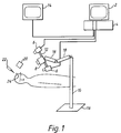
- the system consists of the following main components.
- a workstation computer 2 with processor having a display monitor and keyboard and/or mouse for normal computer interaction. An internal loudspeaker is also required for some system functions. Pre-operative data, images and surgical plans are loaded into this machine before surgery starts.
- a video frame grabber/video display card 4 is hosted by the workstation 2. At least one or more video cameras 6 are connected to the frame grabber. (In a different configuration, the cameras might be attached to, or use the optics of, the surgeon's operating microscope).
- a structured light projector 8 and slide is also provided. The projector is essentially a conventional slide projector, with appropriate lens to ensure the required field of projection and focus. The projected slide is as shown in Figure 2. The breaks in the vertical bars are required to simplify processing algorithms.
- a stand 10 is provided for the cameras and projector.
- the stand is required to position the cameras and projector in a suitable position for viewing the relevant part of the patient.
- the stand consists of two main parts. Firstly, a base 16 and arms 18.
- the stand and arms are used to position the cameras 6 and projector 8 in the correct general viewing position. This is usually above the patient's chest or head for an operation on the head. In plan view, the surgeon, the surgical wound and the cameras should be placed in a straight line approximately.
- a camera and projector mount 12 is provided for the cameras and projector. The stand is required to position the cameras and projector in a suitable position for viewing the relevant part of the patient.
- the stand consists of two main parts. Firstly, a base 16 and arms 18.
- the stand and arms are used to position the cameras 6 and projector 8 in the correct general viewing position. This is usually above the patient's chest or head for an operation on the head. In plan view, the surgeon, the surgical wound and the cameras should be placed in a straight line approximately
- the mount 12 allows the position of the field of view of the cameras 6 and projector 8 to be adjusted from the general viewing position set by the placement of the stand and arms, using a pan-and-tilt device.
- the mount should allow a range of alternative spacings of cameras and projector and alternative vergeance angles so that the set-up can be adjusted for the particular operation in question.
- a video display monitor 14 is connected to the frame grabber and display card 4.
- a camera calibration tile 20 is provided for calibration purposes.
- the camera calibration tile is a flat plate with an accuracy measured array of dots on it.
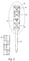
- a video pointer handle and probe 22 is a hand-held instrument.
- the hand-held component of the video-based pointer consists of a patterned handle with a probe-tool attachment 32 such that the probe is rigidly fixed with respect to the handle in a known position when in use.
- Use of a bayonet fitting or similar fitting between handle and probe enables different tools to be attached to the handle (knives, suckers) for different purposes.
- the patterned handle is marked as shown in Figure 3.
- the handle has finger-grips positioned, either at the side of it or behind the patterned face-plate, so that the surgeon's fingers do not obscure the patterning when the pointer is in use, though the system can work with partial obscuration of the patterning.
- the patterning consists of two components. Firstly, a Binary Acquisition Target (BAT) 26. This is a symbol designed for quick detection and orientation by image processing algorithms. The shown symbol is one possibility, but there are others, e.g. the linear BAT 28 also shown in Figure 3. This linear target may also be used for tracking purposes.
- BAT Binary Acquisition Target
- This linear target may also be used for tracking purposes.
- a Tracking Pattern 30 This is a set of marking designed to be suitable for video tracking purposes using the tracking algorithms, as described in GB Patent Application Number 9114518.5.
- the drawn pattern is one example as many variations of this are possible.
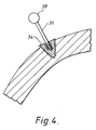
- the Intra-Operative Markers (IOMs) 24, Figure 1 may take several forms, though in all cases the markers need to be rigidly attached (directly or indirectly) to the patient when in use. Individual markers may be attached separately to the patient by screws which screw into the bone. These markers consists of three parts, a base section 34 which screws into the bone and a post 36 and a head 38, which screws into the base, as shown in Figure 4. (The separable design allows the post and head to be removed temporarily and later replaced in the same position if it obstructs some part of the surgical procedure. Alternatively, a one-piece marker might be used where the surgical procedure allows). A minimum of three such markers are required. The head of the marker is finished in a bright matte finish to provide good visual contrast against its background.
- the shape of the marker-head is to enable it to be quickly and accurately located by image processing algorithms, thus a spherical head is very suitable, but other designs (e.g. ellipsoids, circular discs) might be used instead.
- individual markers may be used which attach separately at convenient points to the Mayfield clamp, or similar clamp holding the patient, or to a separate dedicated clamp attached to the patient, or to the operating table.
- the heads of these markers are as described above.
- These markers may also be made in two parts for temporary removal, and may include a patterned block, containing a BAT and a tracking pattern similar to that used on the pointer handle. This is attached directly to the patient by a mechanism similar to a Mayfield clamp.
- part of the marker may be detachable for ease of use, and may include a patterned block as described above, but attached to the Mayfield clamp holding the patient, or to the operating table.
- the first step is camera set-up and calibration. With the patient lying on the operating table and clamped, if part of the surgical procedure, but not yet draped for surgery, the cameras 6 and projector 8 are positioned and adjusted to provide a suitable field of view. The calibration tile 20 is then held in the overlapping fields of view of the cameras and a set of pairs of images are captured, each pair of images consists of a simultaneously captured image from each camera.
- the next step is the use of calibration algorithms, as described by Harris and Teeder above, running on the workstation 2, to calculate the relative position and orientation of the cameras 6 and parameters describing the imaging geometry of each camera (e.g. focal length, aspect ratio, image distortions). This process must be repeated if the cameras are moved relative to each other or if their imaging geometry is disturbed, but otherwise the cameras can be moved to a different view point or to view a different direction without repeating the calibration procedure.
- calibration algorithms as described by Harris and Teeder above, running on the workstation 2
- the next step is the intra-operative skin surface measurement.
- the bar-patterned slide ( Figure 2) is projected onto the patient's skin and a pair of images is captured from the cameras.
- a processing algorithm running on the workstation 2 the shape and position of a section of skin surface illuminated by the projector is calculated relative to a particular camera. The processing will now be described.
- a dense and accurate 3D representation of the (shaven) face or upper head is needed to permit matching to the surface extracted from MR or CT imagers. Accuracy's of better than 1mm are believed required. Note that the upper head will consist of a single smooth, continuous surface.
- Measurements of the surface will be performed using one or more cameras, for speed of acquisition and density of results.
- the surface is by itself devoid of prominent visual features, so visual features must be imposed on the surface.
- To obtain high accuracy (sub-pixel), support from a local region of the image is needed.
- One option for the surface features is a fine texture, but this has the disadvantages of variable accuracy, and the need to know the local surface slope (which will stretch the observed texture).
- the preferred option is to use dark-light edges, imposed on the surface either by projection or 'painting'. These can be consistently located to high accuracy, and can be relatively dense.
- a Canny-type process is used, with a smoothing mask of size smooth (bold type is used to note algorithm parameters), and up to Nhysteresis steps of hysteresis to grow from the high threshold edgels into the low threshold edgels.
- the thresholds are obtained adaptively by taking the first moment of the distribution of edge strengths, the low threshold being a percentage of the high threshold.
- the density is limited by the size of the smoothing mask used in edge extraction - placing the edges closer together then this will cause the edges to be mis-positioned, as the support mask samples neighbouring edge structures.
- edges cannot be accurately located at junctions and sharp bends, and for this reason, a number, safety , of the first and last edgels of an edge are discarded. Edges shorter than min_length are discarded. Perhaps the strongest disadvantage of dark-light edges is the possibility of incorrect labelling of the edges - they have no distinguishing attributes excepting their polarity. This could be overcome by use of a chequerboard, but measurement accuracy will be lost near the junctions.
- Stereo calibration is essentially a solved problem, though there could be some difficulties with telephoto lenses.
- Using a conventional binocular stereo configuration with the cameras spaced apart horizontally, the dark-light edges that give the greatest accuracy will be perpendicular to the epi-polar lines, thus they should be largely vertical in the images. Edges that are parallel with the epi-polar lines give no depth information, and this is another point against using a chequerboard.
- the adjacency between edges is first determined by sending out a set of 'feelers' on the image perpendicular to the edge, and noting which edges they first collide with.
- the feelers are sent out at an interval of poke-step between edgels along an edge, and have maximum length poke-length .
- the pair of edges with the greatest commonality are first labelled as 1 and 2.
- the edge with the greatest commonality with the previously labelled edges is found, and appropriately labelled. This continues until no new edges are labelled.
- the difference in labelling between the two images is currently determined by introducing randomly positioned breaks in the edges, which are seen as the start and end of edges. Each break should be able to be epi-polar matched between the images, though great accuracy is not expected, as it may be on a sharp curve.
- the epi-polar matching is deemed to be successful if it is within a distance of epi-polar-thresh pixels. This distinguishes between valid and invalid labelling differences.
- the labelling difference which is most popular is selected.
- each labelled pair of edges are considered separately.
- the epi-polar line is constructed in the secondary camera image, and the pair of consecutive edgels in the secondary image that straddle the epi-polar line are found. By intersecting the epi-polar line and the line joining the straddling edgels, the intersection point is found.
- reciprocal depth varies linearly along the epi-polar line (in homogeneous co-ordinates).
- the start of the epi-polar line is location of the prime camera pin-hole, and the end of the epi-polar line has a reciprocal depth of zero.
- a number, safety , of the first and last edgels of an edge are discarded because they may be inaccurate.
- the local orientation of both edges must be within an angle of epi-polar-angle degrees to the vertical.
- the 3D edgels can be used to construct a triangular planar facet surface by use of Delaunay triangulation. Note every edgel is needed, since they are correlated, and edgels at an interval of delaunay-step are selected. Delaunay triangulation is performed in the prime image, and the resulting triangles interpreted as planar facets. This produces a single-valued surface. Any triangle with an edge exceeding max-triangle-size in length is discarded to stop the interpolation becoming too distant from the observations.
- the next step is the registration of intra-operatively and pre-operatively measured skin surfaces.
- a processing algorithm running on the workstation 2
- the shape of the skin measured, as described above is registered to the shape of the corresponding section of skin previously generated by analysis of pre-operative data. This results in the calculation of the co-ordinate transformation, T, between the pre-operative data and positions measured in theatre relative to the specified camera, as described above.
- the processing algorithm to match the pre-operative and intra-operatively measured surfaces may be based on chamfer match procedures (D G L Hill and D J Hawkes, "Medical image registration using knowledge of adjacency of anatomical structures", Image and Vision Computing 12(3) 1994, in press).
- a distance transform is calculated for the surface extracted from the pre-operative data, and is held as a set of voxels whose value represents the shortest distance to the pre-operative measurement of the scalp surface.
- a series of trial registrations are then attempted, by projecting points on the intra-operatively measured skin into the pre-operative co-ordinates. For each trial registration, the distance values of the voxels addressed by the projected points are summed to produce a cost of the trial.
- the final registration is taken as the minimum cost pose, found by using a genetic algorithm to refine an initial coarse estimate. Alternative methods are possible.
- the next step is the marking of planned craniotomy position.
- the surgeon is assisted in marking on the patient the planned site of craniotomy. This may be done in several ways.
- the live video output of a selected camera 6 is displayed to the surgeon with a graphical overlay generated by the frame grabber/video display 4.
- the overlay shows the outline of the planned craniotomy as if seen from the position of the selected camera.
- the position of this overlay can be calculated in the workstation, from its planned position relative to the pre-operative data and the transformation, T.
- the surgeon now marks the skin surface manually, in the normal way, but he looks at the video display to ensure that the marker pen and plan are in alignment.
- the marker pen used by the surgeon is fitted to the patterned handle of the video pointer 22.
- the position of the marker-tip is now tracked relative to the camera 6, and, by means of the transformation, T, its position relative to pre-operative images and plans can be calculated.
- the surgeon may now mark the planned craniotomy on the patient, by observing the position of the pen-tip on a display of pre-operative data or by listening to a audio signal indicating the proximity of the pen-tip to the planned position.
- the next step is the placement and modelling of intra-operative markers 24. Having marked the craniotomy position on the patient, the surgeon now places IOMs 24 at positions of convenience (but within the field of view of the cameras 6), either attaching a patterned block or individual markers to the Mayfield clamp, or operating table or directly to the patient, depending on the type of IOM in use.
- the position of the markers 24 and position and shape of the skin surface is now measured, relative to the camera system.
- the skin surface is measured, as described above. (This step can be omitted if the position of the cameras and patient has remained unchanged since that step was performed).
- a pair of images is also captured, without the patterned illumination from the projector 8. These images are processed in the workstation to determine the layout and position of marker pin heads (if separate markers were used) or to determine the position of the IOM block (if a block were used). With independent markers, the position of each marker head is calculated relative to the camera system.
- the processing algorithms will now be described.
- the pin tracking module is designed to find movement of the patient relative to the camera 6.
- the program works in two modes, 'create' and 'find'.
- create mode the individual marker pin positions are measured and stored in a file as the model with which pin positions are compared after patient-camera movement.
- find mode is operated, in which the new 3D pin positions are measured, and the old and new positions compared to calculate the relative movement.
- the steps in create mode are:
- Circles are found in each image as follows.
- a local mean removal (LMR) algorithm is applied which subtracts off the local background intensity, so removing noise and enhancing edges.
- the LMR code then assigns a class number to each pixel, by comparing it with pre-set thresholds. This 'class' image is then stored as the working image.
- a connected component finder algorithm is applied, which searches for groups of connected pixels of the same class, and labels each group as an object. It also finds the outline pixels for each object. Each object is examined to see if it satisfies the criteria for being a candidate to be a circle, i.e. width, height, and class are checked.
- Candidate circles are checked by the circle-finding routine, which fits a circle to the object outline, using a general least squares minimisation routine, and returns its radius, centre and error in fit. Those with acceptable errors are stored as a list of circles. Matching circles in the two images are identified using epi-polar matching, and their 3D positions calculated, using the known camera position. The 3D positions are stored as the pin model.
- Steps 1-3 in 'find mode' are identical to those described above.
- the 3D positions of the pins are stored in an array to form the object to which the pin model is to be matched.
- the pin model is read in and the two sets of pin positions passed to a closed-form least-squares minimisation algorithm which finds the best-fit motion of the model about the camera position to bring it onto the object position. It is necessary to tell the algorithm which model pin matches which object pin before the fit is performed.
- the pins are placed in a circle, it is easy to order them according to angle about their centroid giving N possible match arrangements for N pins.
- the tracking algorithms may be used to determine its position as hereinater described.
- the intra-operative and pre-operative measurement of the skin surface are now registered again, as described above, and the resulting updated transformation, T, is used to calculate the position of the markers relative to the pre-operative images and plans. This information is stored for future use following relative movement of camera and patient.
- Image processing algorithms for locating the binary acquisition target, shown in Figure 3 proceed in a series of steps.
- the first steps segment potential BAT objects from the field of view, as follows:
- This process can be repeated for images from each of the cameras and the resulting set of pose estimates can be integrated for improved accuracy.
- the tracking pattern is tracked using the tracking algorithms as described in GB Patent Application Number 9114518.5.
- the accuracy of this phase is improved by an extension of the tracking algorithms to use information from two or more cameras 6.
- T the transformation, T, the position of the pointer 22 or tool-tip can be superimposed on displays of pre-operative images or plans. As the tracking algorithms track its target in orientation as well as position, the orientation of the pointer can be displayed. Should the system fail to track the pointer, this can be detected by the system and an audible warning generated.
- Registration of intra-operatively and pre-operatively measured patient features revealed in surgery In the course of surgery, other patient features will be revealed to the intra-operative cameras.
- a particular example is the network of pial blood vessels revealed after removal of the dural membrane.
- tissue may rise or fall on opening the craniotomy, and tissue may be misplaced relative to its pre-operative position.
- the intra-operative position and shape of these blood vessels can be measured by processing a new pair of images and the feature registered to pre-operative measurements.
- This registration provides a second estimate that transformation, T. This second estimate may be used to replace or refine the original estimate of T. Similar techniques may be applied to other patient features.
- T the transformation, T, must be re-calculated. If the skin surface is no longer visible, for example, because of surgical wadding and drapes, this may be done by capturing a new pair of images containing the IOMs 24 (without projector illumination). Where the IOMs 24 consists of a patterned block, its new intra-operative position may be measured, as described above, and T can be updated because the IOM's position relative to pre-operative data has been calculated, as described above.
- the newly captured pair of images is used to make a second measurement of the marker head positions and a further registration algorithm estimates the best common transformation, T, between original and current IOM positions.
- the processing algorithms for this operation have been described above with respect to the placement of the IOM's.
- the transformation, T, between the camera system and pre-operative images and plans can now be revised.
- the sources of movement which can be accommodated depend on the type and fixing of IOM used. All the types described above can be used to accommodate deliberate movement of the operating table or camera and projector mount. If movement occurs accidentally because the head slips in the Mayfield support clamp, then recovery from this situation requires the IOMs to have been fixed directly to patient.
- Intra-operative visualisation of pre-operative plans may be required by the surgeon at various stages in surgery. This may be done, as previously described, by overlaying transformed planning data on live video from a selected camera.
Abstract
Description
- This invention concerns assistance to a surgeon performing an operation who has planned his work from images obtained from pre-operative medical imagers such as X-ray Computer Tomography (CT) or Magnetic Resonance (MR) Imagers. The invention's main concern is neurosurgery though other applications are possible. At the time of surgery, the surgeon would benefit from a means of relating visually detectable patient features to the pre-operatively generated images and plans. This process is known as localisation.
- A number of partially successful localisation methods have been developed. One set of methods is known as frame-based stereotaxy [reviewed by D G T Thomas, N D Kitchen: "Minimally Invasive Surgery - Neurosurgery" British Medical Journal
Vol 308, 8 January 1994]. In these methods a frame is attached rigidly to the patient, by screws into the skull, before pre-operative imaging and remains in place in surgery. The design of the frame is such that it is visible in the pre-operative imagery and the surgery is planned in terms of measurements relative to the frame, so that the plan can be carried out by means of scales and graduations marked on the frame and visible to the surgeon in-theatre. This approach has the following disadvantages: - The need for surgery may not have been determined at the time of imaging so a frame may not have been in place, in which case second scan would be required.
- The frame is painful for the patient and there are infection risks due to the invasive form of attachment. (Some forms of frame have been developed where part of the frame is detachable, which makes it slightly more comfortable but the infection risks are unchanged. Other forms of frame use bite-blocks (which fix via mouldings of the patient's teeth); these are less accurate because of the lack of rigidity in the fixing).
- The frame itself can obstruct the surgeon's access, limiting the type of surgery which can be performed.
- The other set of methods are known as frame-less or open-stereotaxy. Here, localisation is achieved using a patient feature (which is visible in pre-operative imagery) or a set of features and a corresponding feature or features locatable intra-operatively (i.e. in-theatre). These features provide a common reference for surgical planning and implementation of the plan in-theatre [see Thomas and Kitchen above]. These methods generally achieve localisation in the following way:
- The patient's head is clamped using a device such as a Mayfield clamp, to keep it stationary. [The Mayfield clamp is one of a number of devices developed for this purpose. This description will assume use of a Mayfield clamp, but it is not specific to it].
- A three-dimensional (3-D) digitiser, sometimes referred to as a pointer in this context, i.e. an instrument which can record the 3D position of its probe tip, is used to measure the position of uniquely identifiable patient features relative to some fixed co-ordinate system in the operating theatre.
- The features of the patient, visible in the pre-operative imagery, corresponding to those whose position has been measured, as described above, are identified by manually marking their position on a computer display of the pre-operative data. The computer generating these displays has access to the output of the 3D digitiser and the pre-operative images and planning data.
- Using the measurements of corresponding points, in the coordinate frame of the digitiser and in the co-ordinate frame of the pre-operative data, the co-ordinate transformation (between these two frames of co-ordinates) is calculated by a computer program.
- With the transformation between digitiser co-ordinates and the pre-operative image co-ordinates known, the transformed position of the digitiser probe-tip, or a surgical instrument attached to the digitiser, can be plotted on computer displays of the pre-operative data or display, enabling the surgeon to locate his instruments to some pre-planned position or identify on the pre-operative data some visually observed feature, revealed during surgery.
- The existing frameless stereotactic methods have disadvantages arising from restrictions due to nature of the 3D digitiser employed. A number of different techniques have been developed. [For references see A C F Colchester et al, "VISLAN: Combining Intra-Operative Video and Pre-Operative Images for Surgical Guidance" to be published in Proc. Applications of Computer Vision in Medical Image Processing Ed: G M Wells III, Menlo Park, AAAI Spring Symposium March 1994, AAAI Press]. A system, with a mechanical arm digitiser, is inherently difficult to manoeuvre and is time consuming to use if numerous features must be located to achieve registration; systems using acoustic or LED beacons require the hand-held pointer of the digitiser to have trailing wires or an internal power supply resulting in complexity in design and certification. Other disadvantages of the existing approaches are:
- Loss of accuracy resulting from errors in the manual identification of patient features. (These can be reduced by the use of markers attached to the patient, if this is done before pre-operative imaging, but this carries risks of infection with markers held by screws into bone or errors due to skin movement if markers are attached to the skin by glue).
- Loss of localisation capabilities, or errors, due to accidental or deliberate movement of the patient. The problem can be reduced by including a means of measuring the position of the clamp holding the patient, but this requires the patient to remain fixed in the clamp throughout surgery.
- An aim of the present invention is to provide apparatus and a method of achieving localisation in frameless stereotaxy which does not suffer from the above mentioned problems.
- According to the present invention there is provided apparatus for computer assisted surgery comprising camera means for viewing part of a patient's body, projector means for projecting a predetermined pattern of light onto the patient's body which is viewed by said camera means, processing and controlling means including image processing algorithms arranged to process said images from said camera means, and superimpose said images on images generated from data prestored in said controlling and processing means, display means for displaying said images and superimposed images, a passive pointer means having a predetermined pattern, which is viewed by said camera means and recognisable by said controlling and processing means, which is arranged to determine the position of a tip of said pointer means and orientation of said pointer means in relation to said patient's body and display said position on said display means with respect to said images generated from said data prestored in said controlling and processing means.
- According to the present invention there is provided a method for use in computer aided surgery comprises the steps of:
generating at least one three dimensional image from a CT, MR or X-ray scan of part of a patient's body, projecting a predetermined pattern of light onto said part of said patient's body, viewing said pattern by camera means, generating a three dimensional image from said viewed pattern of light, combining said three dimensional images to give a common frame of reference, and, using a passive pointer means having a predetermined pattern enabling processing algorithms to determine the position of a tip of said passive pointer means and orientation of said pointer means in relation to the patient's body, and thereby identify the position of said pointer means in relation to the image generated from the CT, MR or X-ray scan. - An embodiment of the present invention will now be described with reference to the accompanying drawings, wherein,
- FIGURE 1 shows a pictorial diagram of the apparatus required to perform the invention;
- FIGURE 2 shows the patterned slide used in the projector shown in Figure 1;
- FIGURE 3 shows a pointer handle and probe, with an alternative linear acquisition target, and,
- FIGURE 4 shows an intra-operative marker pin connected to bone.
- Referring to the drawings, the invention as described provides an alternative method of achieving localisation in frameless stereotaxy by using video cameras and a structured light projector to obtain intra-operative information about the position of patient features and of surgical instruments or pointers. The advantages of this method are that:
- The video-based pointer can be freely hand-held without trailing wires or mechanical encumbrances.
- The pointer does not contain active components, simplifying its design, certification, and sterilisation.
- The position and shape of the surface feature, e.g. the patient's skin, can be measured very quickly using the cameras and projector without the laborious use of the 3D pointer.
- The position of other features of the patient, such as blood vessels revealed during surgery, can be measured quickly with cameras alone, to provide a means of refining the transformation between the video camera system and the pre-operative images and plans.
- The system does not require the use of special attachments to the patient during pre-operative imaging.
- The errors or loss of capability due to accidental or deliberate movement of the patient can be detected and corrected by a number of methods, e.g. the use of markers attached intra-operatively to the patient, or supporting frame or operating table, at positions of convenience to the surgeon, or the use of patient positioning based on patient features such as revealed blood vessels.
- As surgery progresses, the accuracy of registration to be refined is permitted using revealed patient features such as blood vessels.
- Considering now the system components, and referring to Figure 1, the system consists of the following main components.
- A workstation computer 2 with processor is provided having a display monitor and keyboard and/or mouse for normal computer interaction. An internal loudspeaker is also required for some system functions. Pre-operative data, images and surgical plans are loaded into this machine before surgery starts. A video frame grabber/video display card 4 is hosted by the workstation 2. At least one or more video cameras 6 are connected to the frame grabber. (In a different configuration, the cameras might be attached to, or use the optics of, the surgeon's operating microscope). A structured
light projector 8 and slide is also provided. The projector is essentially a conventional slide projector, with appropriate lens to ensure the required field of projection and focus. The projected slide is as shown in Figure 2. The breaks in the vertical bars are required to simplify processing algorithms. Different densities of bars may be used and different slides or more (or less) closely spaced bars and with different patterns or breaks may be used depending on the spatial resolution required. Astand 10 is provided for the cameras and projector. The stand is required to position the cameras and projector in a suitable position for viewing the relevant part of the patient. The stand consists of two main parts. Firstly, abase 16 andarms 18. The stand and arms are used to position the cameras 6 andprojector 8 in the correct general viewing position. This is usually above the patient's chest or head for an operation on the head. In plan view, the surgeon, the surgical wound and the cameras should be placed in a straight line approximately. Secondly, a camera andprojector mount 12. Themount 12 allows the position of the field of view of the cameras 6 andprojector 8 to be adjusted from the general viewing position set by the placement of the stand and arms, using a pan-and-tilt device. The mount should allow a range of alternative spacings of cameras and projector and alternative vergeance angles so that the set-up can be adjusted for the particular operation in question. A video display monitor 14 is connected to the frame grabber and display card 4. Acamera calibration tile 20 is provided for calibration purposes. The camera calibration tile is a flat plate with an accuracy measured array of dots on it. The calibration tile and its use are described by C G Harris and A Teeder "Geometric Camera Calibration for Vision-Based Navigation", Proceedings of IFAC International Workshop on Autonomous Vehicles, 18-21 April 1993, Southampton UK, pp 77-82. A video pointer handle and probe 22 is a hand-held instrument. The hand-held component of the video-based pointer consists of a patterned handle with a probe-tool attachment 32 such that the probe is rigidly fixed with respect to the handle in a known position when in use. Use of a bayonet fitting or similar fitting between handle and probe enables different tools to be attached to the handle (knives, suckers) for different purposes. The patterned handle is marked as shown in Figure 3. The handle has finger-grips positioned, either at the side of it or behind the patterned face-plate, so that the surgeon's fingers do not obscure the patterning when the pointer is in use, though the system can work with partial obscuration of the patterning. The patterning consists of two components. Firstly, a Binary Acquisition Target (BAT) 26. This is a symbol designed for quick detection and orientation by image processing algorithms. The shown symbol is one possibility, but there are others, e.g. thelinear BAT 28 also shown in Figure 3. This linear target may also be used for tracking purposes. Secondly, aTracking Pattern 30. This is a set of marking designed to be suitable for video tracking purposes using the tracking algorithms, as described in GB Patent Application Number 9114518.5. The drawn pattern is one example as many variations of this are possible. - The Intra-Operative Markers (IOMs) 24, Figure 1, may take several forms, though in all cases the markers need to be rigidly attached (directly or indirectly) to the patient when in use. Individual markers may be attached separately to the patient by screws which screw into the bone. These markers consists of three parts, a
base section 34 which screws into the bone and apost 36 and ahead 38, which screws into the base, as shown in Figure 4. (The separable design allows the post and head to be removed temporarily and later replaced in the same position if it obstructs some part of the surgical procedure. Alternatively, a one-piece marker might be used where the surgical procedure allows). A minimum of three such markers are required. The head of the marker is finished in a bright matte finish to provide good visual contrast against its background. The shape of the marker-head is to enable it to be quickly and accurately located by image processing algorithms, thus a spherical head is very suitable, but other designs (e.g. ellipsoids, circular discs) might be used instead. For example, individual markers may be used which attach separately at convenient points to the Mayfield clamp, or similar clamp holding the patient, or to a separate dedicated clamp attached to the patient, or to the operating table. The heads of these markers are as described above. These markers may also be made in two parts for temporary removal, and may include a patterned block, containing a BAT and a tracking pattern similar to that used on the pointer handle. This is attached directly to the patient by a mechanism similar to a Mayfield clamp. As described above, part of the marker may be detachable for ease of use, and may include a patterned block as described above, but attached to the Mayfield clamp holding the patient, or to the operating table. - Considering now the system operation, the system is operated in the following stages which are described in the context of a surgical craniotomy.
- The first step is camera set-up and calibration. With the patient lying on the operating table and clamped, if part of the surgical procedure, but not yet draped for surgery, the cameras 6 and
projector 8 are positioned and adjusted to provide a suitable field of view. Thecalibration tile 20 is then held in the overlapping fields of view of the cameras and a set of pairs of images are captured, each pair of images consists of a simultaneously captured image from each camera. - The next step is the use of calibration algorithms, as described by Harris and Teeder above, running on the workstation 2, to calculate the relative position and orientation of the cameras 6 and parameters describing the imaging geometry of each camera (e.g. focal length, aspect ratio, image distortions). This process must be repeated if the cameras are moved relative to each other or if their imaging geometry is disturbed, but otherwise the cameras can be moved to a different view point or to view a different direction without repeating the calibration procedure.
- The next step is the intra-operative skin surface measurement. Using the
projector 8, the bar-patterned slide (Figure 2) is projected onto the patient's skin and a pair of images is captured from the cameras. Using a processing algorithm running on the workstation 2, the shape and position of a section of skin surface illuminated by the projector is calculated relative to a particular camera. The processing will now be described. - A dense and accurate 3D representation of the (shaven) face or upper head is needed to permit matching to the surface extracted from MR or CT imagers. Accuracy's of better than 1mm are believed required. Note that the upper head will consist of a single smooth, continuous surface.
- Measurements of the surface will be performed using one or more cameras, for speed of acquisition and density of results. The surface is by itself devoid of prominent visual features, so visual features must be imposed on the surface. To obtain high accuracy (sub-pixel), support from a local region of the image is needed. One option for the surface features is a fine texture, but this has the disadvantages of variable accuracy, and the need to know the local surface slope (which will stretch the observed texture).
- The preferred option is to use dark-light edges, imposed on the surface either by projection or 'painting'. These can be consistently located to high accuracy, and can be relatively dense. A Canny-type process is used, with a smoothing mask of size smooth (bold type is used to note algorithm parameters), and up to Nhysteresis steps of hysteresis to grow from the high threshold edgels into the low threshold edgels. The thresholds are obtained adaptively by taking the first moment of the distribution of edge strengths, the low threshold being a percentage of the high threshold. The density is limited by the size of the smoothing mask used in edge extraction - placing the edges closer together then this will cause the edges to be mis-positioned, as the support mask samples neighbouring edge structures. Note that edges cannot be accurately located at junctions and sharp bends, and for this reason, a number, safety, of the first and last edgels of an edge are discarded. Edges shorter than min_length are discarded. Perhaps the strongest disadvantage of dark-light edges is the possibility of incorrect labelling of the edges - they have no distinguishing attributes excepting their polarity. This could be overcome by use of a chequerboard, but measurement accuracy will be lost near the junctions.
- Three-dimension measurements of the location of surface features will be performed using stereo. One option is to use calibrated structured light, observed by a single camera, but this presents the problem of how to calibrate the structured light, and how stable is the calibration over time. The alternative selected is to use uncalibrated (but structured) surface edge features, observed by binocular (or trinocular) stereo cameras. Stereo calibration is essentially a solved problem, though there could be some difficulties with telephoto lenses. Using a conventional binocular stereo configuration, with the cameras spaced apart horizontally, the dark-light edges that give the greatest accuracy will be perpendicular to the epi-polar lines, thus they should be largely vertical in the images. Edges that are parallel with the epi-polar lines give no depth information, and this is another point against using a chequerboard.
- Using stereo on dark-light edges requires the correct labelling of edges in each image, as there is no local test to check that the correct edges have been matched. The labelling problem is solved by firstly obtaining the correct relative labelling on each image individually, and then finding the difference in labelling between the two images.
- To obtain the labelling on a single image, the adjacency between edges is first determined by sending out a set of 'feelers' on the image perpendicular to the edge, and noting which edges they first collide with. The feelers are sent out at an interval of poke-step between edgels along an edge, and have maximum length poke-length. The pair of edges with the greatest commonality are first labelled as 1 and 2. Next, the edge with the greatest commonality with the previously labelled edges is found, and appropriately labelled. This continues until no new edges are labelled.
- The difference in labelling between the two images is currently determined by introducing randomly positioned breaks in the edges, which are seen as the start and end of edges. Each break should be able to be epi-polar matched between the images, though great accuracy is not expected, as it may be on a sharp curve. The epi-polar matching is deemed to be successful if it is within a distance of epi-polar-thresh pixels. This distinguishes between valid and invalid labelling differences. The labelling difference which is most popular is selected.
- Once labelling has been achieved, each labelled pair of edges are considered separately. For each edgel in the prime camera (camera 0), the epi-polar line is constructed in the secondary camera image, and the pair of consecutive edgels in the secondary image that straddle the epi-polar line are found. By intersecting the epi-polar line and the line joining the straddling edgels, the intersection point is found. Now reciprocal depth varies linearly along the epi-polar line (in homogeneous co-ordinates). The start of the epi-polar line is location of the prime camera pin-hole, and the end of the epi-polar line has a reciprocal depth of zero. As before, a number, safety, of the first and last edgels of an edge are discarded because they may be inaccurate. To provide further security, the local orientation of both edges must be within an angle of epi-polar-angle degrees to the vertical.
- The 3D edgels can be used to construct a triangular planar facet surface by use of Delaunay triangulation. Note every edgel is needed, since they are correlated, and edgels at an interval of delaunay-step are selected. Delaunay triangulation is performed in the prime image, and the resulting triangles interpreted as planar facets. This produces a single-valued surface. Any triangle with an edge exceeding max-triangle-size in length is discarded to stop the interpolation becoming too distant from the observations.
- The next step is the registration of intra-operatively and pre-operatively measured skin surfaces. Using a processing algorithm, running on the workstation 2, the shape of the skin measured, as described above, is registered to the shape of the corresponding section of skin previously generated by analysis of pre-operative data. This results in the calculation of the co-ordinate transformation, T, between the pre-operative data and positions measured in theatre relative to the specified camera, as described above.
- The processing algorithm to match the pre-operative and intra-operatively measured surfaces may be based on chamfer match procedures (D G L Hill and D J Hawkes, "Medical image registration using knowledge of adjacency of anatomical structures", Image and Vision Computing 12(3) 1994, in press). In this technique, a distance transform is calculated for the surface extracted from the pre-operative data, and is held as a set of voxels whose value represents the shortest distance to the pre-operative measurement of the scalp surface. A series of trial registrations are then attempted, by projecting points on the intra-operatively measured skin into the pre-operative co-ordinates. For each trial registration, the distance values of the voxels addressed by the projected points are summed to produce a cost of the trial. The final registration is taken as the minimum cost pose, found by using a genetic algorithm to refine an initial coarse estimate. Alternative methods are possible.
- The next step is the marking of planned craniotomy position. With the patient and cameras remaining in the positions used, as described above, the surgeon is assisted in marking on the patient the planned site of craniotomy. This may be done in several ways. The live video output of a selected camera 6 is displayed to the surgeon with a graphical overlay generated by the frame grabber/video display 4. The overlay shows the outline of the planned craniotomy as if seen from the position of the selected camera. The position of this overlay can be calculated in the workstation, from its planned position relative to the pre-operative data and the transformation, T. The surgeon now marks the skin surface manually, in the normal way, but he looks at the video display to ensure that the marker pen and plan are in alignment. The marker pen used by the surgeon is fitted to the patterned handle of the
video pointer 22. Using thevideo pointer 22, the position of the marker-tip is now tracked relative to the camera 6, and, by means of the transformation, T, its position relative to pre-operative images and plans can be calculated. The surgeon may now mark the planned craniotomy on the patient, by observing the position of the pen-tip on a display of pre-operative data or by listening to a audio signal indicating the proximity of the pen-tip to the planned position. - The next step is the placement and modelling of
intra-operative markers 24. Having marked the craniotomy position on the patient, the surgeon now placesIOMs 24 at positions of convenience (but within the field of view of the cameras 6), either attaching a patterned block or individual markers to the Mayfield clamp, or operating table or directly to the patient, depending on the type of IOM in use. - The position of the
markers 24 and position and shape of the skin surface is now measured, relative to the camera system. The skin surface is measured, as described above. (This step can be omitted if the position of the cameras and patient has remained unchanged since that step was performed). A pair of images is also captured, without the patterned illumination from theprojector 8. These images are processed in the workstation to determine the layout and position of marker pin heads (if separate markers were used) or to determine the position of the IOM block (if a block were used). With independent markers, the position of each marker head is calculated relative to the camera system. The processing algorithms will now be described. - The pin tracking module is designed to find movement of the patient relative to the camera 6. The program works in two modes, 'create' and 'find'. In create mode, the individual marker pin positions are measured and stored in a file as the model with which pin positions are compared after patient-camera movement. After movement, find mode is operated, in which the new 3D pin positions are measured, and the old and new positions compared to calculate the relative movement.
- The steps in create mode are:
- Two images are captured and stored in arrays.
- Circles are found in each image as follows. A local mean removal (LMR) algorithm is applied which subtracts off the local background intensity, so removing noise and enhancing edges. The LMR code then assigns a class number to each pixel, by comparing it with pre-set thresholds. This 'class' image is then stored as the working image. For each working image, a connected component finder algorithm is applied, which searches for groups of connected pixels of the same class, and labels each group as an object. It also finds the outline pixels for each object. Each object is examined to see if it satisfies the criteria for being a candidate to be a circle, i.e. width, height, and class are checked. Candidate circles are checked by the circle-finding routine, which fits a circle to the object outline, using a general least squares minimisation routine, and returns its radius, centre and error in fit. Those with acceptable errors are stored as a list of circles. Matching circles in the two images are identified using epi-polar matching, and their 3D positions calculated, using the known camera position. The 3D positions are stored as the pin model.
- Steps 1-3 in 'find mode' are identical to those described above. The 3D positions of the pins are stored in an array to form the object to which the pin model is to be matched. The pin model is read in and the two sets of pin positions passed to a closed-form least-squares minimisation algorithm which finds the best-fit motion of the model about the camera position to bring it onto the object position. It is necessary to tell the algorithm which model pin matches which object pin before the fit is performed. In practice, as the pins are placed in a circle, it is easy to order them according to angle about their centroid giving N possible match arrangements for N pins.
- With an IOM block, whose shape and patterning is already known, the tracking algorithms may be used to determine its position as hereinater described.
- The intra-operative and pre-operative measurement of the skin surface are now registered again, as described above, and the resulting updated transformation, T, is used to calculate the position of the markers relative to the pre-operative images and plans. This information is stored for future use following relative movement of camera and patient.
- At this point surgery now commences, and at various times the surgeon may wish to use the video-based pointer 22 (or its handle with another instrument attached) to help relate some intra-operative position to the pre-operative data. This may be done by real-time processing of images in two phases as follows:
- Acquisition - The surgeon holds the
pointer 22 still, with its patterning facing the cameras. Processing algorithms locate the BAT in corresponding images from each camera and an approximate estimate of the position of the BAT, relative to the cameras is calculated. This position is used as an initial estimate for the tracking phase. Successful completion of this phase is indicated by an audible signal and the surgeon may start to move the pointer. The processing algorithm for BAT acquisition will now be described. - Image processing algorithms for locating the binary acquisition target, shown in Figure 3, proceed in a series of steps.
- The first steps segment potential BAT objects from the field of view, as follows:
- 1) The input grey-level image is processed by local mean removal and thresholding to produce a binary output image.
- 2) Connected (black-pixel) components are then found. The following steps identify the BAT from the set of connected components.
- 3) The set of components arising from step 2 are filtered according to component size to remove very small items resulting from image noise and clutter.
- 4) The convex hull of each remaining connected component is calculated.
- 5) Significant concavities in object boundaries are found by comparing the true boundary with the convex hull, and objects with other than three major concavities are rejected.
- 6) Again by comparing the true boundary with the object's convex hull, the six points marking the end of each concavity are found.
- 7) The distances between opposite pairs of pints from step 6 are compared. In orthographic projection, these distances would be equal for the true BAT, because the expected convex hull is hexagonal, consequently objects with significantly unequal opposite distances can be rejected. In practice the comparison of distances allows for the fact that the viewing geometry has perspective and is not simply orthographic. The remaining steps calculate the pose of the BAT.
- 8) The position and orientation of the BAT, relative to the camera, is now calculated from the image positions of the six points defining the near-hexagonal convex hull, ignoring the rotational ambiguity, using knowledge of the actual dimensions of the BAT and the camera calibration parameters.
- 9) With three possibilities for the pose of the BAT calculated in
step 8, differing only by 120 degree rotations of the BAT, the rotational ambiguity is now resolved by calculating the position of three test pixels, to locate the deepest cut in the BAT's hexagonal convex hull. - This process can be repeated for images from each of the cameras and the resulting set of pose estimates can be integrated for improved accuracy.
- Tracking - Using the BAT position estimate calculated at acquisition, the tracking pattern is tracked using the tracking algorithms as described in GB Patent Application Number 9114518.5. The accuracy of this phase is improved by an extension of the tracking algorithms to use information from two or more cameras 6. Using the transformation, T, the position of the
pointer 22 or tool-tip can be superimposed on displays of pre-operative images or plans. As the tracking algorithms track its target in orientation as well as position, the orientation of the pointer can be displayed. Should the system fail to track the pointer, this can be detected by the system and an audible warning generated. - Registration of intra-operatively and pre-operatively measured patient features revealed in surgery. In the course of surgery, other patient features will be revealed to the intra-operative cameras. A particular example is the network of pial blood vessels revealed after removal of the dural membrane. Depending on the intra-cranial pressure, tissue may rise or fall on opening the craniotomy, and tissue may be misplaced relative to its pre-operative position. The intra-operative position and shape of these blood vessels can be measured by processing a new pair of images and the feature registered to pre-operative measurements. This registration provides a second estimate that transformation, T. This second estimate may be used to replace or refine the original estimate of T. Similar techniques may be applied to other patient features.
- Considering now the re-location of the patient following movement of patient or cameras. From time to time, it may be necessary to move the cameras or the patient, for the convenience of the surgeon to improve surgical access or line of sight, or movement may occur for some accidental reason. Following such movement, the transformation, T, must be re-calculated. If the skin surface is no longer visible, for example, because of surgical wadding and drapes, this may be done by capturing a new pair of images containing the IOMs 24 (without projector illumination). Where the
IOMs 24 consists of a patterned block, its new intra-operative position may be measured, as described above, and T can be updated because the IOM's position relative to pre-operative data has been calculated, as described above. Where individual markers are used, the newly captured pair of images is used to make a second measurement of the marker head positions and a further registration algorithm estimates the best common transformation, T, between original and current IOM positions. The processing algorithms for this operation have been described above with respect to the placement of the IOM's. The transformation, T, between the camera system and pre-operative images and plans can now be revised. - The sources of movement which can be accommodated, depend on the type and fixing of IOM used. All the types described above can be used to accommodate deliberate movement of the operating table or camera and projector mount. If movement occurs accidentally because the head slips in the Mayfield support clamp, then recovery from this situation requires the IOMs to have been fixed directly to patient.
- Intra-operative visualisation of pre-operative plans may be required by the surgeon at various stages in surgery. This may be done, as previously described, by overlaying transformed planning data on live video from a selected camera.
- It will be appreciated that various modifications may be made to the foregoing described procedure and apparatus, are possible which fall within the scope of the invention. For example, any number of cameras may be used, and variations to the algorithms used may be envisaged.
Claims (15)
- Apparatus for computer assisted surgery comprising camera means for viewing part of a patient's body, projector means for projecting a predetermined pattern of light onto the patient's body which is viewed by said camera means, processing and controlling means including image processing algorithms arranged to process said images from said camera means, and superimpose said images on images generated from data prestored in said controlling and processing means, display means for displaying said images and superimposed images, a passive pointer means having a predetermined pattern, which is viewed by said camera means and recognisable by said controlling and processing means, which is arranged to determine the position of a tip of said pointer means and orientation of said pointer means in relation to said patient's body and display said position on said display means with respect to said images generated from said data prestored in said controlling and processing means.
- Apparatus as claimed in Claim 1, wherein said camera means comprises two or more video cameras to provide a three-dimensional image.
- Apparatus as claimed in Claim 2, wherein calibration means is provided for calibrating said video cameras.
- Apparatus as claimed in any preceding claim, wherein the pointer means comprises a handle having a binary acquisition target thereon for recognition and orientation by image processing algorithms.
- Apparatus as claimed in claim 4, wherein said handle includes a tracking pattern used for video tracking by tracking algorithms.
- Apparatus as claimed in Claim 5, wherein the pointer means includes means for attaching different tools, the position of a tip of each tool and orientation of the tool, in relation to the patients body being determined by said controlling and processing means.
- Apparatus as claimed in any preceding claim, wherein said projector means is a slide projector and said slide comprises a pattern of broken vertical bars, which may be of different densities.
- Apparatus as claimed in any preceding claim, wherein the images generated from prestored data are formed from X-ray images, MR or CT scan images.
- Apparatus as claimed in any preceding claim, wherein marker pins are attached to the part of the patients body to be viewed, and used by said controlling and processing means to compensate for movement of the patient's body.
- Apparatus as claimed in Claim 9, wherein the marker pins comprise a base section adapted to be screwed into the patients bone, a post and a head, said head being adapted to be easily recognised by said image processing algorithms.
- Apparatus as claimed in Claim 10, wherein said head includes a pattern for recognition by said image processing algorithms.
- Apparatus substantially as hereinbefore described with reference to the accompanying drawings.
- A method, for use in computer aided surgery comprising the steps of:
generating at least one three dimensional image from a CT, MR or X-ray scan of part of a patient's body, projecting a predetermined pattern of light onto said part of said patient's body, viewing said pattern by camera means, generating a three dimensional image from said viewed pattern of light, combining said three dimensional images to give a common frame of reference, and, using a passive pointer means having a predetermined pattern enabling processing algorithms to determine the position of a tip of said passive pointer means and orientation of said pointer means in relation to the patient's body, and thereby identify the position of said pointer means in relation to the image generated from the CT, MR or X-ray scan. - A method as claimed in Claim 13, wherein said camera means comprises at least two cameras which are calibrated so that each camera captures the same image, and their relative position and orientation are calculated.
- A method as claimed in Claim 13 or Claim 14, wherein marker pins are positioned on the patient's body, so that any movement thereof is detected and compensated for.
Applications Claiming Priority (2)
| Application Number | Priority Date | Filing Date | Title |
|---|---|---|---|
| GB9405299A GB9405299D0 (en) | 1994-03-17 | 1994-03-17 | Improvements in or relating to video-based systems for computer assisted surgery and localisation |
| GB9405299 | 1994-03-17 |
Publications (3)
| Publication Number | Publication Date |
|---|---|
| EP0672389A2 true EP0672389A2 (en) | 1995-09-20 |
| EP0672389A3 EP0672389A3 (en) | 1996-12-27 |
| EP0672389B1 EP0672389B1 (en) | 1998-08-05 |
Family
ID=10752059
Family Applications (1)
| Application Number | Title | Priority Date | Filing Date |
|---|---|---|---|
| EP95301696A Expired - Lifetime EP0672389B1 (en) | 1994-03-17 | 1995-03-14 | Video-based system for computer assisted surgery and localisation |
Country Status (6)
| Country | Link |
|---|---|
| US (1) | US5792147A (en) |
| EP (1) | EP0672389B1 (en) |
| DE (1) | DE69503814T2 (en) |
| DK (1) | DK0672389T3 (en) |
| ES (1) | ES2119311T3 (en) |
| GB (2) | GB9405299D0 (en) |
Cited By (29)
| Publication number | Priority date | Publication date | Assignee | Title |
|---|---|---|---|---|
| EP0860144A3 (en) * | 1997-02-19 | 1999-04-28 | Picker International, Inc. | Diagnostic imaging |
| WO1999038449A1 (en) * | 1998-01-28 | 1999-08-05 | Cosman Eric R | Optical object tracking system |
| WO1999048432A1 (en) * | 1998-03-26 | 1999-09-30 | Karl Storz Gmbh & Co. Kg | Endoscope adapter which can be detected using computer assisted surgery |
| EP0955935A1 (en) * | 1996-05-15 | 1999-11-17 | Northwestern University | Stereotactic surgical procedure apparatus and method |
| WO2001019271A3 (en) * | 1999-09-15 | 2001-09-27 | Neil David Glossop | Method and system to facilitate image guided surgery |
| EP1279376A2 (en) * | 2001-07-27 | 2003-01-29 | G.D.S. Giorgi Dynamic Stereotaxy S.r.l. | Device and procedure for computer-assisted microsurgery |
| WO2003046290A1 (en) | 2001-11-21 | 2003-06-05 | Roke Manor Research Limited | Detection of undesired objects on surfaces |
| EP1321105A1 (en) * | 2001-12-18 | 2003-06-25 | BrainLAB AG | Superposition of patient X-ray or scanning imaging data and superficial video images |
| EP1330790A2 (en) * | 2000-08-28 | 2003-07-30 | Cognitens Ltd. | Accurately aligning images in digital imaging systems by matching points in the images |
| US6656110B1 (en) | 1997-04-16 | 2003-12-02 | Karl Storz Gmbh & Co. Kg | Endoscopic system |
| EP1470791A1 (en) * | 2003-04-25 | 2004-10-27 | BrainLAB AG | Visualisation apparatus with input means, for the combination of scanned and video images, and visualisation method |
| DE10352556A1 (en) * | 2003-11-08 | 2005-06-09 | Medical Intelligence Medizintechnik Gmbh | Patient identification system and patient positioning method |
| WO2005061031A1 (en) * | 2003-11-28 | 2005-07-07 | Disetronic Licensing Ag | Method and device for determining a position in order to carry out substance discharge |
| WO2005067794A1 (en) * | 2004-01-20 | 2005-07-28 | Marek Mlodzianowski | Device for surgical optical navigation |
| EP1800616A1 (en) * | 2005-12-26 | 2007-06-27 | DePuy Products, Inc. | Computer assisted surgery system with light source |
| JP2008541966A (en) * | 2005-06-09 | 2008-11-27 | アイエフイー インダストリエレ フォーシュング ウント エントヴィックルング ゲーエムベーハー | System and method for non-contact determination and measurement of the spatial position and / or orientation of an object, in particular a medical instrument calibration and test method including a pattern or structure relating to a medical instrument |
| US7463823B2 (en) | 2003-07-24 | 2008-12-09 | Brainlab Ag | Stereoscopic visualization device for patient image data and video images |
| WO2010020397A1 (en) * | 2008-08-18 | 2010-02-25 | Naviswiss Ag | Medical measuring system, surgical intervention methods, and use of a medical measuring system |
| WO2010133994A1 (en) * | 2009-05-20 | 2010-11-25 | Koninklijke Philips Electronics N.V. | Data acquisition and visualization mode for low dose intervention guidance in computed tomography |
| FR2946243A1 (en) * | 2009-06-04 | 2010-12-10 | Inst Curie | Patient positioning method for radiation therapy system, involves associating markers constituted by base to patient, where sphere is adapted to be fixed on base in concentric manner with radio-opaque element |
| EP2277441A1 (en) * | 2009-07-22 | 2011-01-26 | Surgica Robotica S.p.A. | Method for generating images of a human body zone undergoing a surgical operation by means of an apparatus for minimally invasive surgical procedures |
| WO2011107575A1 (en) * | 2010-03-04 | 2011-09-09 | Siemens Aktiengesellschaft | Medical examination and/or treatment device |
| WO2012049038A1 (en) * | 2010-10-11 | 2012-04-19 | Siemens Aktiengesellschaft | Operation navigation system having structured light |
| CN102743227A (en) * | 2011-04-19 | 2012-10-24 | 迈柯唯公司 | Operating assembly including observation apparatus, the use of such an operating assembly, and an operating facility |
| EP2967657A4 (en) * | 2013-03-15 | 2016-11-02 | Univ Nebraska | On-board tool tracking system and methods of computer assisted surgery |
| JPWO2016056327A1 (en) * | 2014-10-07 | 2017-07-20 | 帝人ファーマ株式会社 | Transcranial magnetic stimulation system |
| WO2019029934A1 (en) * | 2017-08-11 | 2019-02-14 | Brainlab Ag | Video based patient registration and tracking |
| US11291507B2 (en) | 2018-07-16 | 2022-04-05 | Mako Surgical Corp. | System and method for image based registration and calibration |
| US11431990B2 (en) | 2015-06-04 | 2022-08-30 | Thales Holdings Uk Plc | Video compression with increased fidelity near horizon |
Families Citing this family (156)
| Publication number | Priority date | Publication date | Assignee | Title |
|---|---|---|---|---|
| US6331180B1 (en) | 1988-05-03 | 2001-12-18 | Sherwood Services Ag | Target-centered stereotaxtic surgical arc system with reorientatable arc axis |
| US6675040B1 (en) | 1991-01-28 | 2004-01-06 | Sherwood Services Ag | Optical object tracking system |
| US6006126A (en) | 1991-01-28 | 1999-12-21 | Cosman; Eric R. | System and method for stereotactic registration of image scan data |
| US6405072B1 (en) * | 1991-01-28 | 2002-06-11 | Sherwood Services Ag | Apparatus and method for determining a location of an anatomical target with reference to a medical apparatus |
| GB2291967A (en) * | 1994-07-28 | 1996-02-07 | Merck & Co Inc | Optical scanning position checking system |
| US6978166B2 (en) | 1994-10-07 | 2005-12-20 | Saint Louis University | System for use in displaying images of a body part |
| AU3950595A (en) * | 1994-10-07 | 1996-05-06 | St. Louis University | Surgical navigation systems including reference and localization frames |
| KR19990029038A (en) * | 1995-07-16 | 1999-04-15 | 요아브 빨띠에리 | Free aiming of needle ceramic |
| US6684098B2 (en) * | 1996-08-16 | 2004-01-27 | Brigham And Women's Hospital, Inc. | Versatile stereotactic device and methods of use |
| US6083163A (en) * | 1997-01-21 | 2000-07-04 | Computer Aided Surgery, Inc. | Surgical navigation system and method using audio feedback |
| DE19715202B4 (en) * | 1997-04-11 | 2006-02-02 | Brainlab Ag | Referencing device with a mouthpiece |
| US6226548B1 (en) | 1997-09-24 | 2001-05-01 | Surgical Navigation Technologies, Inc. | Percutaneous registration apparatus and method for use in computer-assisted surgical navigation |
| US7507088B2 (en) * | 1997-09-30 | 2009-03-24 | Cadent Ltd. | Method for comparing orthodontic element placement |
| IL121872A (en) * | 1997-09-30 | 2002-12-01 | Cadent Ltd | Placing an orthodontic element on a tooth surface |
| US6334772B1 (en) * | 1997-09-30 | 2002-01-01 | Cadent Ltd. | Placing an orthodontic element on a tooth surface |
| WO1999023452A1 (en) * | 1997-11-04 | 1999-05-14 | Synthes Ag Chur | Device for referencing a system of co-ordinates |
| WO1999023956A1 (en) | 1997-11-05 | 1999-05-20 | Synthes Ag, Chur | Virtual representation of a bone or a bone joint |
| US6011987A (en) * | 1997-12-08 | 2000-01-04 | The Cleveland Clinic Foundation | Fiducial positioning cup |
| EP1047337B1 (en) * | 1998-01-14 | 2007-10-10 | Leonard Reiffel | System to stabilize an irradiated internal target |
| DE19821611A1 (en) * | 1998-05-14 | 1999-11-18 | Syrinx Med Tech Gmbh | Recording method for spatial structure of three-dimensional surface, e.g. for person recognition |
| EP1079756B1 (en) | 1998-05-28 | 2004-08-04 | Orthosoft, Inc. | Interactive computer-assisted surgical system |
| GB2338786B (en) * | 1998-06-26 | 2002-11-27 | Anthony David Hall | Inspection device and method |
| GB2340716A (en) * | 1998-08-11 | 2000-02-23 | Nicholas Collett | Patient position monitoring system |
| JP2001061861A (en) | 1999-06-28 | 2001-03-13 | Siemens Ag | System having image photographing means and medical work station |
| US6314311B1 (en) * | 1999-07-28 | 2001-11-06 | Picker International, Inc. | Movable mirror laser registration system |
| US6206891B1 (en) | 1999-09-14 | 2001-03-27 | Medeye Medical Technology Ltd. | Device and method for calibration of a stereotactic localization system |
| GB9923795D0 (en) | 1999-10-09 | 1999-12-08 | British Aerospace | Micropositioning system |
| DE19960020A1 (en) * | 1999-12-13 | 2001-06-21 | Ruediger Marmulla | Device for optical detection and referencing between data set, surgical site and 3D marker system for instrument and bone segment navigation |
| WO2001047413A1 (en) * | 1999-12-23 | 2001-07-05 | Lifschitz & Co. | Ultrasonic marker for use in surgery |
| US6618076B1 (en) | 1999-12-23 | 2003-09-09 | Justsystem Corporation | Method and apparatus for calibrating projector-camera system |
| US7635390B1 (en) | 2000-01-14 | 2009-12-22 | Marctec, Llc | Joint replacement component having a modular articulating surface |
| WO2001076496A1 (en) * | 2000-04-10 | 2001-10-18 | Karl Storz Gmbh & Co. Kg | Medical device for positioning data on intraoperative images |
| US6533455B2 (en) | 2000-08-31 | 2003-03-18 | Siemens Aktiengesellschaft | Method for determining a coordinate transformation for use in navigating an object |
| DE10137914B4 (en) * | 2000-08-31 | 2006-05-04 | Siemens Ag | Coordinate transformation determination for medical application, involves determining coordinate transformation relation between coordinate systems of instrument and patient using respective coordinate transformations |
| US6926673B2 (en) * | 2000-11-28 | 2005-08-09 | Roke Manor Research Limited | Optical tracking systems |
| GB0028939D0 (en) * | 2000-11-28 | 2001-01-10 | Roke Manor Research | A tracking system for ultrasound probes |
| EP2320431A3 (en) * | 2000-12-08 | 2012-09-05 | Loma Linda University Medical Center | Proton beam therapy control system |
| DE60232316D1 (en) | 2001-02-27 | 2009-06-25 | Smith & Nephew Inc | DEVICE FOR TOTAL KNEE CONSTRUCTION |
| KR20020069793A (en) * | 2001-02-28 | 2002-09-05 | 장한 | Video camera system installed in portable stand for photographing the scene of operation |
| DE10110093A1 (en) * | 2001-03-02 | 2002-09-26 | Juergen Wahrburg | Device for displaying the spatial position of a surgical instrument during an operation and for comparison of actual and theoretical positions so that a correction signal can be generated |
| US7708741B1 (en) | 2001-08-28 | 2010-05-04 | Marctec, Llc | Method of preparing bones for knee replacement surgery |
| US7016522B2 (en) * | 2002-01-15 | 2006-03-21 | Siemens Medical Solutions Usa, Inc. | Patient positioning by video imaging |
| ATE275881T1 (en) * | 2002-03-01 | 2004-10-15 | Brainlab Ag | OPERATIONAL LAMP WITH CAMERA SYSTEM FOR 3D REFERENCE |
| WO2003077101A2 (en) * | 2002-03-06 | 2003-09-18 | Z-Kat, Inc. | System and method for using a haptic device in combination with a computer-assisted surgery system |
| US7831292B2 (en) * | 2002-03-06 | 2010-11-09 | Mako Surgical Corp. | Guidance system and method for surgical procedures with improved feedback |
| US8010180B2 (en) | 2002-03-06 | 2011-08-30 | Mako Surgical Corp. | Haptic guidance system and method |
| US8996169B2 (en) | 2011-12-29 | 2015-03-31 | Mako Surgical Corp. | Neural monitor-based dynamic haptics |
| US11202676B2 (en) | 2002-03-06 | 2021-12-21 | Mako Surgical Corp. | Neural monitor-based dynamic haptics |
| US7912532B2 (en) * | 2002-06-13 | 2011-03-22 | Moeller-Wedel Gmbh | Method and instrument for surgical navigation |
| US20110015518A1 (en) | 2002-06-13 | 2011-01-20 | Martin Schmidt | Method and instrument for surgical navigation |
| US6978167B2 (en) * | 2002-07-01 | 2005-12-20 | Claron Technology Inc. | Video pose tracking system and method |
| US20040068263A1 (en) * | 2002-10-04 | 2004-04-08 | Benoit Chouinard | CAS bone reference with articulated support |
| MXPA05007215A (en) * | 2003-01-02 | 2005-09-12 | Univ Loma Linda Med | Configuration management and retrieval system for proton beam therapy system. |
| WO2004070292A2 (en) * | 2003-02-03 | 2004-08-19 | Scott, Bryan | Electrical system for controlling ventilation registers |
| EP1615577A2 (en) * | 2003-02-04 | 2006-01-18 | Orthosoft, Inc. | Cas modular bone reference assembly and limb position measurement system |
| US7049594B2 (en) * | 2003-03-28 | 2006-05-23 | Howmedica Leibinger | Position sensing sensor, method and system |
| AU2004266644B2 (en) * | 2003-08-12 | 2009-07-16 | Vision Rt Limited | Patient positioning system for radiation therapy system |
| EP2368600B1 (en) | 2003-08-12 | 2016-09-21 | Loma Linda University Medical Center | Modular patient support system |
| US7862570B2 (en) | 2003-10-03 | 2011-01-04 | Smith & Nephew, Inc. | Surgical positioners |
| US7764985B2 (en) | 2003-10-20 | 2010-07-27 | Smith & Nephew, Inc. | Surgical navigation system component fault interfaces and related processes |
| WO2005048851A1 (en) | 2003-11-14 | 2005-06-02 | Smith & Nephew, Inc. | Adjustable surgical cutting systems |
| US7403811B2 (en) * | 2004-03-01 | 2008-07-22 | Scimed Life Systems, Inc. | Method of catheter tracking using image information |
| US7567833B2 (en) * | 2004-03-08 | 2009-07-28 | Stryker Leibinger Gmbh & Co. Kg | Enhanced illumination device and method |
| WO2005104978A1 (en) | 2004-04-21 | 2005-11-10 | Smith & Nephew, Inc. | Computer-aided methods, systems, and apparatuses for shoulder arthroplasty |
| DE102004022803B4 (en) * | 2004-05-08 | 2009-08-27 | Ziehm Imaging Gmbh | Method and device for navigation of an X-ray diagnostic device |
| FR2871363B1 (en) * | 2004-06-15 | 2006-09-01 | Medtech Sa | ROBOTIZED GUIDING DEVICE FOR SURGICAL TOOL |
| US7374103B2 (en) * | 2004-08-03 | 2008-05-20 | Siemens Corporate Research, Inc. | Object localization |
| JP2008531091A (en) | 2005-02-22 | 2008-08-14 | スミス アンド ネフュー インコーポレーテッド | In-line milling system |
| CA2826925C (en) | 2005-02-22 | 2017-01-24 | Mako Surgical Corp. | Haptic guidance system and method |
| US7889905B2 (en) * | 2005-05-23 | 2011-02-15 | The Penn State Research Foundation | Fast 3D-2D image registration method with application to continuously guided endoscopy |
| US7756563B2 (en) * | 2005-05-23 | 2010-07-13 | The Penn State Research Foundation | Guidance method based on 3D-2D pose estimation and 3D-CT registration with application to live bronchoscopy |
| US20070066917A1 (en) * | 2005-09-20 | 2007-03-22 | Hodorek Robert A | Method for simulating prosthetic implant selection and placement |
| CN101299971B (en) * | 2005-11-03 | 2012-09-26 | 奥索瑟夫特公司 | Multifaceted tracker device for computer-assisted surgery |
| US20070156066A1 (en) * | 2006-01-03 | 2007-07-05 | Zimmer Technology, Inc. | Device for determining the shape of an anatomic surface |
| DE102006004692A1 (en) * | 2006-01-31 | 2007-08-09 | Siemens Ag | An imaging medical device and method for such a device |
| CA2644574C (en) | 2006-03-17 | 2016-11-08 | Zimmer, Inc. | Methods of predetermining the contour of a resected bone surface and assessing the fit of a prosthesis on the bone |
| US20070236514A1 (en) * | 2006-03-29 | 2007-10-11 | Bracco Imaging Spa | Methods and Apparatuses for Stereoscopic Image Guided Surgical Navigation |
| US8442281B2 (en) * | 2006-04-28 | 2013-05-14 | The Invention Science Fund I, Llc | Artificially displaying information relative to a body |
| WO2007136769A2 (en) | 2006-05-19 | 2007-11-29 | Mako Surgical Corp. | Method and apparatus for controlling a haptic device |
| US8560047B2 (en) | 2006-06-16 | 2013-10-15 | Board Of Regents Of The University Of Nebraska | Method and apparatus for computer aided surgery |
| US7728868B2 (en) | 2006-08-02 | 2010-06-01 | Inneroptic Technology, Inc. | System and method of providing real-time dynamic imagery of a medical procedure site using multiple modalities |
| US8565853B2 (en) | 2006-08-11 | 2013-10-22 | DePuy Synthes Products, LLC | Simulated bone or tissue manipulation |
| US7587024B2 (en) * | 2006-09-01 | 2009-09-08 | Siemens Aktiengesellschaft | Particle beam irradiation system |
| EP2095374A4 (en) | 2006-11-21 | 2012-05-30 | Univ Loma Linda Med | Device and method for immobilizing patients for breast radiation therapy |
| US20080163118A1 (en) * | 2006-12-29 | 2008-07-03 | Jason Wolf | Representation of file relationships |
| US9037215B2 (en) | 2007-01-31 | 2015-05-19 | The Penn State Research Foundation | Methods and apparatus for 3D route planning through hollow organs |
| US20090156895A1 (en) * | 2007-01-31 | 2009-06-18 | The Penn State Research Foundation | Precise endoscopic planning and visualization |
| US8672836B2 (en) * | 2007-01-31 | 2014-03-18 | The Penn State Research Foundation | Method and apparatus for continuous guidance of endoscopy |
| US9179983B2 (en) | 2007-08-14 | 2015-11-10 | Zimmer, Inc. | Method of determining a contour of an anatomical structure and selecting an orthopaedic implant to replicate the anatomical structure |
| FR2920085B1 (en) * | 2007-08-24 | 2012-06-15 | Univ Grenoble 1 | IMAGING SYSTEM FOR THREE-DIMENSIONAL OBSERVATION OF AN OPERATIVE FIELD |
| EP2044884B1 (en) * | 2007-10-02 | 2015-12-09 | Brainlab AG | Detection and determination of changes in position of structural parts of a body |
| US8149384B2 (en) * | 2007-12-17 | 2012-04-03 | Advanced Micro Devices, Inc. | Method and apparatus for extracting dose and focus from critical dimension data |
| WO2009094646A2 (en) | 2008-01-24 | 2009-07-30 | The University Of North Carolina At Chapel Hill | Methods, systems, and computer readable media for image guided ablation |
| CN101951853B (en) | 2008-02-22 | 2013-01-23 | 洛马林达大学医学中心 | Systems and methods for characterizing spatial distortion in 3D imaging systems |
| US8340379B2 (en) | 2008-03-07 | 2012-12-25 | Inneroptic Technology, Inc. | Systems and methods for displaying guidance data based on updated deformable imaging data |
| EP2153794B1 (en) | 2008-08-15 | 2016-11-09 | Stryker European Holdings I, LLC | System for and method of visualizing an interior of a body |
| US8554307B2 (en) | 2010-04-12 | 2013-10-08 | Inneroptic Technology, Inc. | Image annotation in image-guided medical procedures |
| US11464578B2 (en) | 2009-02-17 | 2022-10-11 | Inneroptic Technology, Inc. | Systems, methods, apparatuses, and computer-readable media for image management in image-guided medical procedures |
| US8641621B2 (en) | 2009-02-17 | 2014-02-04 | Inneroptic Technology, Inc. | Systems, methods, apparatuses, and computer-readable media for image management in image-guided medical procedures |
| US8690776B2 (en) | 2009-02-17 | 2014-04-08 | Inneroptic Technology, Inc. | Systems, methods, apparatuses, and computer-readable media for image guided surgery |
| US8792614B2 (en) | 2009-03-31 | 2014-07-29 | Matthew R. Witten | System and method for radiation therapy treatment planning using a memetic optimization algorithm |
| JP6034695B2 (en) | 2009-10-01 | 2016-11-30 | ローマ リンダ ユニヴァーシティ メディカル センター | Ion-induced impact ionization detector and its use |
| US8867820B2 (en) * | 2009-10-07 | 2014-10-21 | Microsoft Corporation | Systems and methods for removing a background of an image |
| US8564534B2 (en) | 2009-10-07 | 2013-10-22 | Microsoft Corporation | Human tracking system |
| US7961910B2 (en) | 2009-10-07 | 2011-06-14 | Microsoft Corporation | Systems and methods for tracking a model |
| US8963829B2 (en) * | 2009-10-07 | 2015-02-24 | Microsoft Corporation | Methods and systems for determining and tracking extremities of a target |
| CA2718686C (en) * | 2009-10-20 | 2015-07-14 | Imris Inc. | Imaging system using markers |
| WO2011134083A1 (en) | 2010-04-28 | 2011-11-03 | Ryerson University | System and methods for intraoperative guidance feedback |
| US8435033B2 (en) | 2010-07-19 | 2013-05-07 | Rainbow Medical Ltd. | Dental navigation techniques |
| US8657809B2 (en) | 2010-09-29 | 2014-02-25 | Stryker Leibinger Gmbh & Co., Kg | Surgical navigation system |
| US9921712B2 (en) | 2010-12-29 | 2018-03-20 | Mako Surgical Corp. | System and method for providing substantially stable control of a surgical tool |
| US9119655B2 (en) | 2012-08-03 | 2015-09-01 | Stryker Corporation | Surgical manipulator capable of controlling a surgical instrument in multiple modes |
| US11911117B2 (en) | 2011-06-27 | 2024-02-27 | Board Of Regents Of The University Of Nebraska | On-board tool tracking system and methods of computer assisted surgery |
| CN106913366B (en) | 2011-06-27 | 2021-02-26 | 内布拉斯加大学评议会 | On-tool tracking system and computer-assisted surgery method |
| US9766441B2 (en) | 2011-09-22 | 2017-09-19 | Digital Surgicals Pte. Ltd. | Surgical stereo vision systems and methods for microsurgery |
| US9330477B2 (en) | 2011-09-22 | 2016-05-03 | Digital Surgicals Pte. Ltd. | Surgical stereo vision systems and methods for microsurgery |
| EP3238649B1 (en) | 2011-09-28 | 2018-12-05 | Brainlab AG | Self-localizing medical device |
| WO2013116240A1 (en) | 2012-01-30 | 2013-08-08 | Inneroptic Technology, Inc. | Multiple medical device guidance |
| US20150025548A1 (en) | 2012-03-08 | 2015-01-22 | Neutar, Llc | Patient and Procedure Customized Fixation and Targeting Devices for Stereotactic Frames |
| US9820818B2 (en) | 2012-08-03 | 2017-11-21 | Stryker Corporation | System and method for controlling a surgical manipulator based on implant parameters |
| KR102235965B1 (en) | 2012-08-03 | 2021-04-06 | 스트리커 코포레이션 | Systems and methods for robotic surgery |
| US9226796B2 (en) | 2012-08-03 | 2016-01-05 | Stryker Corporation | Method for detecting a disturbance as an energy applicator of a surgical instrument traverses a cutting path |
| CN102920513B (en) * | 2012-11-13 | 2014-10-29 | 吉林大学 | Augmented reality system experiment platform based on projector |
| JP6167511B2 (en) * | 2012-12-04 | 2017-07-26 | セイコーエプソン株式会社 | Document camera and document camera control method |
| EP2996615B1 (en) | 2013-03-13 | 2019-01-30 | Stryker Corporation | System for arranging objects in an operating room in preparation for surgical procedures |
| US10314559B2 (en) | 2013-03-14 | 2019-06-11 | Inneroptic Technology, Inc. | Medical device guidance |
| US10105149B2 (en) | 2013-03-15 | 2018-10-23 | Board Of Regents Of The University Of Nebraska | On-board tool tracking system and methods of computer assisted surgery |
| MY170323A (en) | 2013-03-15 | 2019-07-17 | Synaptive Medical Inc | Intelligent positioning system and methods therefore |
| CA2892554C (en) | 2013-03-15 | 2017-04-18 | Synaptive Medical (Barbados) Inc. | System and method for dynamic validation, correction of registration for surgical navigation |
| MY177484A (en) | 2013-03-15 | 2020-09-16 | Synaptive Medical Inc | Systems and methods for navigation and simulation of minimally invasive therapy |
| ITRM20130308A1 (en) * | 2013-05-28 | 2014-11-29 | Glomeria Therapeutics S R L | CONNECTION DEVICE |
| US9285666B2 (en) * | 2014-04-16 | 2016-03-15 | Eue Medical Technology Co., Ltd. | Object guide system |
| US20150366628A1 (en) * | 2014-06-18 | 2015-12-24 | Covidien Lp | Augmented surgical reality environment system |
| US9901406B2 (en) | 2014-10-02 | 2018-02-27 | Inneroptic Technology, Inc. | Affected region display associated with a medical device |
| WO2016071325A1 (en) * | 2014-11-06 | 2016-05-12 | Koninklijke Philips N.V. | Skin treatment system |
| US10188467B2 (en) | 2014-12-12 | 2019-01-29 | Inneroptic Technology, Inc. | Surgical guidance intersection display |
| US9905000B2 (en) * | 2015-02-19 | 2018-02-27 | Sony Corporation | Method and system for surgical tool localization during anatomical surgery |
| DE102015205214A1 (en) * | 2015-03-23 | 2016-09-29 | Universität Siegen | A method for an integrated operation planning and support system for operations on the human or animal body and a device therefor |
| WO2016154557A1 (en) * | 2015-03-26 | 2016-09-29 | Universidade De Coimbra | Methods and systems for computer-aided surgery using intra-operative video acquired by a free moving camera |
| EP3284252B1 (en) | 2015-04-13 | 2021-07-21 | Universidade De Coimbra | Methods and systems for camera characterization in terms of response function, color, and vignetting under non-uniform illumination |
| US9949700B2 (en) | 2015-07-22 | 2018-04-24 | Inneroptic Technology, Inc. | Medical device approaches |
| US9675319B1 (en) | 2016-02-17 | 2017-06-13 | Inneroptic Technology, Inc. | Loupe display |
| EP3439558B1 (en) | 2016-04-06 | 2021-06-02 | X-Nav Technologies, LLC | System for providing probe trace fiducial-free tracking |
| AU2017257887B2 (en) * | 2016-04-27 | 2019-12-19 | Biomet Manufacturing, Llc. | Surgical system having assisted navigation |
| US10278778B2 (en) | 2016-10-27 | 2019-05-07 | Inneroptic Technology, Inc. | Medical device navigation using a virtual 3D space |
| TWI609358B (en) * | 2016-12-16 | 2017-12-21 | 國立成功大學 | Generating method for orthognathic surgical planning |
| EP3554414A1 (en) | 2016-12-16 | 2019-10-23 | MAKO Surgical Corp. | Techniques for modifying tool operation in a surgical robotic system based on comparing actual and commanded states of the tool relative to a surgical site |
| US10593240B2 (en) | 2017-06-08 | 2020-03-17 | Medos International Sàrl | User interface systems for sterile fields and other working environments |
| US11259879B2 (en) | 2017-08-01 | 2022-03-01 | Inneroptic Technology, Inc. | Selective transparency to assist medical device navigation |
| US11484365B2 (en) | 2018-01-23 | 2022-11-01 | Inneroptic Technology, Inc. | Medical image guidance |
| US10959857B2 (en) * | 2018-02-27 | 2021-03-30 | Mako Surgical Corp. | Registration tools, systems, and methods |
| US11819297B2 (en) * | 2018-12-20 | 2023-11-21 | Think Surgical, Inc. | Light guided digitization method to register a bone |
| US11538570B2 (en) | 2019-01-04 | 2022-12-27 | Gentex Corporation | Authentication and informational displays with adaptive lighting array |
| CN109464196B (en) * | 2019-01-07 | 2021-04-20 | 北京和华瑞博医疗科技有限公司 | Surgical navigation system adopting structured light image registration and registration signal acquisition method |
| EP3712900A1 (en) * | 2019-03-20 | 2020-09-23 | Stryker European Holdings I, LLC | Technique for processing patient-specific image data for computer-assisted surgical navigation |
| US20210298863A1 (en) * | 2020-03-27 | 2021-09-30 | Trumpf Medizin Systeme GmbH & Co. KG. | Augmented reality for a surgical system |
Citations (3)
| Publication number | Priority date | Publication date | Assignee | Title |
|---|---|---|---|---|
| WO1990005494A1 (en) * | 1988-11-18 | 1990-05-31 | Istituto Neurologico 'carlo Besta' | Process and apparatus particularly for guiding neurosurgical operations |
| EP0429148A1 (en) * | 1989-11-15 | 1991-05-29 | George S. Allen | Method and apparatus for imaging the anatomy |
| DE4225112C1 (en) * | 1992-07-30 | 1993-12-09 | Bodenseewerk Geraetetech | Instrument position relative to processing object measuring apparatus - has measuring device for measuring position of instrument including inertia sensor unit |
Family Cites Families (19)
| Publication number | Priority date | Publication date | Assignee | Title |
|---|---|---|---|---|
| US4722056A (en) * | 1986-02-18 | 1988-01-26 | Trustees Of Dartmouth College | Reference display systems for superimposing a tomagraphic image onto the focal plane of an operating microscope |
| CH672722A5 (en) * | 1986-06-24 | 1989-12-29 | Marco Brandestini | |
| DE3632878C2 (en) * | 1986-09-26 | 1994-11-17 | Siemens Ag | Device for positioning the head of a patient to take an x-ray |
| DE3717871C3 (en) * | 1987-05-27 | 1995-05-04 | Georg Prof Dr Schloendorff | Method and device for reproducible visual representation of a surgical intervention |
| JPS6472736A (en) * | 1987-09-14 | 1989-03-17 | Toshiba Corp | Mri apparatus |
| CA1288176C (en) * | 1987-10-29 | 1991-08-27 | David C. Hatcher | Method and apparatus for improving the alignment of radiographic images |
| US4991579A (en) * | 1987-11-10 | 1991-02-12 | Allen George S | Method and apparatus for providing related images over time of a portion of the anatomy using fiducial implants |
| US5247555A (en) * | 1988-10-28 | 1993-09-21 | Nucletron Manufacturing Corp. | Radiation image generating system and method |
| US5099846A (en) * | 1988-12-23 | 1992-03-31 | Hardy Tyrone L | Method and apparatus for video presentation from a variety of scanner imaging sources |
| US5098426A (en) * | 1989-02-06 | 1992-03-24 | Phoenix Laser Systems, Inc. | Method and apparatus for precision laser surgery |
| GB9015594D0 (en) * | 1990-07-16 | 1991-04-24 | Plessey Roke Manor Res | Tracking arrangements and systems |
| US5129911A (en) * | 1991-03-11 | 1992-07-14 | Siczek Bernard W | Orbital aiming device |
| US5155435A (en) * | 1991-08-08 | 1992-10-13 | The Regents Of The University Of California | Method and apparatus for performing interventional medical procedures using MR imaging of interventional device superimposed with ghost patient image |
| US5389101A (en) * | 1992-04-21 | 1995-02-14 | University Of Utah | Apparatus and method for photogrammetric surgical localization |
| US5517990A (en) * | 1992-11-30 | 1996-05-21 | The Cleveland Clinic Foundation | Stereotaxy wand and tool guide |
| US5526812A (en) * | 1993-06-21 | 1996-06-18 | General Electric Company | Display system for enhancing visualization of body structures during medical procedures |
| IL109939A (en) * | 1993-06-21 | 1997-09-30 | Gen Electric | Display system for enhancing visualization of body structures during medical procedures |
| US5446548A (en) * | 1993-10-08 | 1995-08-29 | Siemens Medical Systems, Inc. | Patient positioning and monitoring system |
| US5414459A (en) * | 1993-11-26 | 1995-05-09 | Bullwinkel; Paul | Fiber optic video glasses and projection system |
-
1994
- 1994-03-17 GB GB9405299A patent/GB9405299D0/en active Pending
-
1995
- 1995-03-14 EP EP95301696A patent/EP0672389B1/en not_active Expired - Lifetime
- 1995-03-14 DE DE69503814T patent/DE69503814T2/en not_active Expired - Lifetime
- 1995-03-14 ES ES95301696T patent/ES2119311T3/en not_active Expired - Lifetime
- 1995-03-14 GB GB9505124A patent/GB2287598B/en not_active Expired - Fee Related
- 1995-03-14 DK DK95301696T patent/DK0672389T3/en active
-
1997
- 1997-07-21 US US08/897,670 patent/US5792147A/en not_active Expired - Fee Related
Patent Citations (3)
| Publication number | Priority date | Publication date | Assignee | Title |
|---|---|---|---|---|
| WO1990005494A1 (en) * | 1988-11-18 | 1990-05-31 | Istituto Neurologico 'carlo Besta' | Process and apparatus particularly for guiding neurosurgical operations |
| EP0429148A1 (en) * | 1989-11-15 | 1991-05-29 | George S. Allen | Method and apparatus for imaging the anatomy |
| DE4225112C1 (en) * | 1992-07-30 | 1993-12-09 | Bodenseewerk Geraetetech | Instrument position relative to processing object measuring apparatus - has measuring device for measuring position of instrument including inertia sensor unit |
Non-Patent Citations (1)
| Title |
|---|
| IEEE TRANSACTIONS ON MEDICAL IMAGING, DEC. 1991, USA, vol. 10, no. 4, ISSN 0278-0062, pages 523-529, XP002014248 CLARYSSE P ET AL: "A computer-assisted system for 3-D frameless localization in stereotaxic MRI" * |
Cited By (51)
| Publication number | Priority date | Publication date | Assignee | Title |
|---|---|---|---|---|
| EP0955935A1 (en) * | 1996-05-15 | 1999-11-17 | Northwestern University | Stereotactic surgical procedure apparatus and method |
| EP0955935A4 (en) * | 1996-05-15 | 2002-02-27 | Univ Northwestern | Stereotactic surgical procedure apparatus and method |
| EP0860144A3 (en) * | 1997-02-19 | 1999-04-28 | Picker International, Inc. | Diagnostic imaging |
| US6832985B2 (en) | 1997-04-16 | 2004-12-21 | Karl Storz Gmbh & Co. Kg | Endoscopic system with instrument position and orientation display |
| US6656110B1 (en) | 1997-04-16 | 2003-12-02 | Karl Storz Gmbh & Co. Kg | Endoscopic system |
| WO1999038449A1 (en) * | 1998-01-28 | 1999-08-05 | Cosman Eric R | Optical object tracking system |
| EP1415609A1 (en) * | 1998-01-28 | 2004-05-06 | Sherwood Services AG | Optical object tracking system |
| WO1999048432A1 (en) * | 1998-03-26 | 1999-09-30 | Karl Storz Gmbh & Co. Kg | Endoscope adapter which can be detected using computer assisted surgery |
| US6468202B1 (en) | 1998-03-26 | 2002-10-22 | Karl Storz Gmbh & Co. Kg | Endoscope adapter which can be detected using computer assisted surgery |
| WO2001019271A3 (en) * | 1999-09-15 | 2001-09-27 | Neil David Glossop | Method and system to facilitate image guided surgery |
| US6317616B1 (en) | 1999-09-15 | 2001-11-13 | Neil David Glossop | Method and system to facilitate image guided surgery |
| EP1330790A4 (en) * | 2000-08-28 | 2006-03-22 | Cognitens Ltd | Accurately aligning images in digital imaging systems by matching points in the images |
| EP1330790A2 (en) * | 2000-08-28 | 2003-07-30 | Cognitens Ltd. | Accurately aligning images in digital imaging systems by matching points in the images |
| EP1279376A3 (en) * | 2001-07-27 | 2003-05-07 | G.D.S. Giorgi Dynamic Stereotaxy S.r.l. | Device and procedure for computer-assisted microsurgery |
| EP1279376A2 (en) * | 2001-07-27 | 2003-01-29 | G.D.S. Giorgi Dynamic Stereotaxy S.r.l. | Device and procedure for computer-assisted microsurgery |
| WO2003046290A1 (en) | 2001-11-21 | 2003-06-05 | Roke Manor Research Limited | Detection of undesired objects on surfaces |
| EP1327421A1 (en) * | 2001-12-18 | 2003-07-16 | BrainLAB AG | Superposition of patient X-ray or scanning imaging data and video images |
| EP1321105A1 (en) * | 2001-12-18 | 2003-06-25 | BrainLAB AG | Superposition of patient X-ray or scanning imaging data and superficial video images |
| US7050845B2 (en) | 2001-12-18 | 2006-05-23 | Brainlab Ag | Projecting patient image data from radioscopic imaging methods and/or tomographic imaging methods onto video images |
| EP1470791A1 (en) * | 2003-04-25 | 2004-10-27 | BrainLAB AG | Visualisation apparatus with input means, for the combination of scanned and video images, and visualisation method |
| US7463823B2 (en) | 2003-07-24 | 2008-12-09 | Brainlab Ag | Stereoscopic visualization device for patient image data and video images |
| DE10352556A1 (en) * | 2003-11-08 | 2005-06-09 | Medical Intelligence Medizintechnik Gmbh | Patient identification system and patient positioning method |
| WO2005061031A1 (en) * | 2003-11-28 | 2005-07-07 | Disetronic Licensing Ag | Method and device for determining a position in order to carry out substance discharge |
| WO2005067794A1 (en) * | 2004-01-20 | 2005-07-28 | Marek Mlodzianowski | Device for surgical optical navigation |
| JP2008541966A (en) * | 2005-06-09 | 2008-11-27 | アイエフイー インダストリエレ フォーシュング ウント エントヴィックルング ゲーエムベーハー | System and method for non-contact determination and measurement of the spatial position and / or orientation of an object, in particular a medical instrument calibration and test method including a pattern or structure relating to a medical instrument |
| US8320612B2 (en) | 2005-06-09 | 2012-11-27 | Naviswiss Ag | System and method for the contactless determination and measurement of a spatial position and/or a spatial orientation of bodies, method for the calibration and testing, in particular, medical tools as well as patterns or structures on, in particular, medical tools |
| EP2377484A1 (en) * | 2005-06-09 | 2011-10-19 | Naviswiss AG | Device and method for contactless determination and measuring of the spatial position and/or spatial orientation of bodies, method for calibrating and testing tools, in particular medical tools, and patterns or structures on tools, in particular medical tools |
| EP1800616A1 (en) * | 2005-12-26 | 2007-06-27 | DePuy Products, Inc. | Computer assisted surgery system with light source |
| US7894872B2 (en) | 2005-12-26 | 2011-02-22 | Depuy Orthopaedics, Inc | Computer assisted orthopaedic surgery system with light source and associated method |
| WO2010020397A1 (en) * | 2008-08-18 | 2010-02-25 | Naviswiss Ag | Medical measuring system, surgical intervention methods, and use of a medical measuring system |
| WO2010133994A1 (en) * | 2009-05-20 | 2010-11-25 | Koninklijke Philips Electronics N.V. | Data acquisition and visualization mode for low dose intervention guidance in computed tomography |
| FR2946243A1 (en) * | 2009-06-04 | 2010-12-10 | Inst Curie | Patient positioning method for radiation therapy system, involves associating markers constituted by base to patient, where sphere is adapted to be fixed on base in concentric manner with radio-opaque element |
| EP2277441A1 (en) * | 2009-07-22 | 2011-01-26 | Surgica Robotica S.p.A. | Method for generating images of a human body zone undergoing a surgical operation by means of an apparatus for minimally invasive surgical procedures |
| CN102781313A (en) * | 2010-03-04 | 2012-11-14 | 西门子公司 | Medical examination and/or treatment device |
| WO2011107575A1 (en) * | 2010-03-04 | 2011-09-09 | Siemens Aktiengesellschaft | Medical examination and/or treatment device |
| WO2012049038A1 (en) * | 2010-10-11 | 2012-04-19 | Siemens Aktiengesellschaft | Operation navigation system having structured light |
| CN102743227A (en) * | 2011-04-19 | 2012-10-24 | 迈柯唯公司 | Operating assembly including observation apparatus, the use of such an operating assembly, and an operating facility |
| EP2515529A1 (en) | 2011-04-19 | 2012-10-24 | Maquet SAS | Surgical assembly comprising a monitoring device, use of such surgical assembly and surgical facility |
| FR2974473A1 (en) * | 2011-04-19 | 2012-10-26 | Maquet S A | MONITORING DEVICE, USE OF SUCH A MONITORING DEVICE AND OPERATION INSTALLATION COMPRISING SUCH A MONITORING DEVICE |
| CN102743227B (en) * | 2011-04-19 | 2014-05-28 | 迈柯唯公司 | Operating assembly including observation apparatus, the use of such an operating assembly, and an operating facility |
| EP2967657A4 (en) * | 2013-03-15 | 2016-11-02 | Univ Nebraska | On-board tool tracking system and methods of computer assisted surgery |
| CN107106860A (en) * | 2014-10-07 | 2017-08-29 | 帝人制药株式会社 | Through cranium magnetic stimulation system |
| JPWO2016056327A1 (en) * | 2014-10-07 | 2017-07-20 | 帝人ファーマ株式会社 | Transcranial magnetic stimulation system |
| EP3205373A4 (en) * | 2014-10-07 | 2017-10-04 | Teijin Pharma Limited | Transcranial magnetic stimulation system |
| US10413744B2 (en) | 2014-10-07 | 2019-09-17 | Teijin Pharma Limited | Transcranial magnetic stimulation system |
| CN107106860B (en) * | 2014-10-07 | 2020-09-22 | 帝人制药株式会社 | Transcranial magnetic stimulation system |
| US11431990B2 (en) | 2015-06-04 | 2022-08-30 | Thales Holdings Uk Plc | Video compression with increased fidelity near horizon |
| WO2019029934A1 (en) * | 2017-08-11 | 2019-02-14 | Brainlab Ag | Video based patient registration and tracking |
| US10918444B2 (en) | 2017-08-11 | 2021-02-16 | Brainlab Ag | Video based patient registration and tracking |
| US11291507B2 (en) | 2018-07-16 | 2022-04-05 | Mako Surgical Corp. | System and method for image based registration and calibration |
| US11806090B2 (en) | 2018-07-16 | 2023-11-07 | Mako Surgical Corp. | System and method for image based registration and calibration |
Also Published As
| Publication number | Publication date |
|---|---|
| GB2287598B (en) | 1998-03-25 |
| GB2287598A (en) | 1995-09-20 |
| US5792147A (en) | 1998-08-11 |
| EP0672389B1 (en) | 1998-08-05 |
| ES2119311T3 (en) | 1998-10-01 |
| DE69503814T2 (en) | 1998-12-03 |
| DK0672389T3 (en) | 1998-12-14 |
| EP0672389A3 (en) | 1996-12-27 |
| DE69503814D1 (en) | 1998-09-10 |
| GB9505124D0 (en) | 1995-05-03 |
| GB9405299D0 (en) | 1994-04-27 |
Similar Documents
| Publication | Publication Date | Title |
|---|---|---|
| EP0672389B1 (en) | Video-based system for computer assisted surgery and localisation | |
| US11612443B2 (en) | Systems, methods and devices to scan 3D surfaces for intra-operative localization | |
| US10593052B2 (en) | Methods and systems for updating an existing landmark registration | |
| US6491702B2 (en) | Apparatus and method for photogrammetric surgical localization | |
| US5389101A (en) | Apparatus and method for photogrammetric surgical localization | |
| EP2953569B1 (en) | Tracking apparatus for tracking an object with respect to a body | |
| US7912532B2 (en) | Method and instrument for surgical navigation | |
| JP2950340B2 (en) | Registration system and registration method for three-dimensional data set | |
| US6275725B1 (en) | Stereotactic optical navigation | |
| EP3254621A1 (en) | 3d image special calibrator, surgical localizing system and method | |
| US5987960A (en) | Tool calibrator | |
| US5795294A (en) | Procedure for the correlation of different coordinate systems in computer-supported, stereotactic surgery | |
| US20150164329A1 (en) | Method and instrument for surgical navigation | |
| US20230329799A1 (en) | Rotating Marker | |
| US20220142730A1 (en) | Fiducial marker | |
| Philip et al. | Stereo augmented reality in the surgical microscope | |
| US10682126B2 (en) | Phantom to determine positional and angular navigation system error | |
| Edwards et al. | Neurosurgical guidance using the stereo microscope | |
| Colchester et al. | Craniotomy simulation and guidance using a stereo video based tracking system (VISLAN) | |
| WO2023036848A1 (en) | Augmented reality surgical navigation system | |
| EP1124201A1 (en) | Method for 3D/2D registration using multiple views and a surface model of an object | |
| Maitland et al. | A Video Based Tracker for use in Computer Aided Surgery. |
Legal Events
| Date | Code | Title | Description |
|---|---|---|---|
| PUAI | Public reference made under article 153(3) epc to a published international application that has entered the european phase |
Free format text: ORIGINAL CODE: 0009012 |
|
| AK | Designated contracting states |
Kind code of ref document: A2 Designated state(s): BE DE DK ES FR GB IT NL SE |
|
| 17P | Request for examination filed |
Effective date: 19960208 |
|
| PUAL | Search report despatched |
Free format text: ORIGINAL CODE: 0009013 |
|
| AK | Designated contracting states |
Kind code of ref document: A3 Designated state(s): BE DE DK ES FR GB IT NL SE |
|
| GRAG | Despatch of communication of intention to grant |
Free format text: ORIGINAL CODE: EPIDOS AGRA |
|
| GRAG | Despatch of communication of intention to grant |
Free format text: ORIGINAL CODE: EPIDOS AGRA |
|
| 17Q | First examination report despatched |
Effective date: 19970523 |
|
| GRAG | Despatch of communication of intention to grant |
Free format text: ORIGINAL CODE: EPIDOS AGRA |
|
| GRAH | Despatch of communication of intention to grant a patent |
Free format text: ORIGINAL CODE: EPIDOS IGRA |
|
| GRAG | Despatch of communication of intention to grant |
Free format text: ORIGINAL CODE: EPIDOS AGRA |
|
| GRAH | Despatch of communication of intention to grant a patent |
Free format text: ORIGINAL CODE: EPIDOS IGRA |
|
| GRAH | Despatch of communication of intention to grant a patent |
Free format text: ORIGINAL CODE: EPIDOS IGRA |
|
| GRAA | (expected) grant |
Free format text: ORIGINAL CODE: 0009210 |
|
| AK | Designated contracting states |
Kind code of ref document: B1 Designated state(s): BE DE DK ES FR GB IT NL SE |
|
| ET | Fr: translation filed | ||
| REF | Corresponds to: |
Ref document number: 69503814 Country of ref document: DE Date of ref document: 19980910 |
|
| REG | Reference to a national code |
Ref country code: ES Ref legal event code: FG2A Ref document number: 2119311 Country of ref document: ES Kind code of ref document: T3 |
|
| REG | Reference to a national code |
Ref country code: DK Ref legal event code: T3 |
|
| PLBE | No opposition filed within time limit |
Free format text: ORIGINAL CODE: 0009261 |
|
| STAA | Information on the status of an ep patent application or granted ep patent |
Free format text: STATUS: NO OPPOSITION FILED WITHIN TIME LIMIT |
|
| 26N | No opposition filed | ||
| REG | Reference to a national code |
Ref country code: GB Ref legal event code: IF02 |
|
| PGFP | Annual fee paid to national office [announced via postgrant information from national office to epo] |
Ref country code: DK Payment date: 20040123 Year of fee payment: 10 |
|
| PGFP | Annual fee paid to national office [announced via postgrant information from national office to epo] |
Ref country code: SE Payment date: 20040304 Year of fee payment: 10 |
|
| PGFP | Annual fee paid to national office [announced via postgrant information from national office to epo] |
Ref country code: NL Payment date: 20040310 Year of fee payment: 10 |
|
| PGFP | Annual fee paid to national office [announced via postgrant information from national office to epo] |
Ref country code: ES Payment date: 20040318 Year of fee payment: 10 |
|
| PGFP | Annual fee paid to national office [announced via postgrant information from national office to epo] |
Ref country code: BE Payment date: 20040519 Year of fee payment: 10 |
|
| PG25 | Lapsed in a contracting state [announced via postgrant information from national office to epo] |
Ref country code: IT Free format text: LAPSE BECAUSE OF NON-PAYMENT OF DUE FEES;WARNING: LAPSES OF ITALIAN PATENTS WITH EFFECTIVE DATE BEFORE 2007 MAY HAVE OCCURRED AT ANY TIME BEFORE 2007. THE CORRECT EFFECTIVE DATE MAY BE DIFFERENT FROM THE ONE RECORDED. Effective date: 20050314 |
|
| PG25 | Lapsed in a contracting state [announced via postgrant information from national office to epo] |
Ref country code: SE Free format text: LAPSE BECAUSE OF NON-PAYMENT OF DUE FEES Effective date: 20050315 Ref country code: ES Free format text: LAPSE BECAUSE OF NON-PAYMENT OF DUE FEES Effective date: 20050315 |
|
| PG25 | Lapsed in a contracting state [announced via postgrant information from national office to epo] |
Ref country code: DK Free format text: LAPSE BECAUSE OF NON-PAYMENT OF DUE FEES Effective date: 20050331 Ref country code: BE Free format text: LAPSE BECAUSE OF NON-PAYMENT OF DUE FEES Effective date: 20050331 |
|
| BERE | Be: lapsed |
Owner name: *UNITED MEDICAL AND DENTAL SCHOOLS GUY'S HOSPITAL Effective date: 20050331 Owner name: *ROKE MANOR RESEARCH LTD Effective date: 20050331 |
|
| PG25 | Lapsed in a contracting state [announced via postgrant information from national office to epo] |
Ref country code: NL Free format text: LAPSE BECAUSE OF NON-PAYMENT OF DUE FEES Effective date: 20051001 |
|
| EUG | Se: european patent has lapsed | ||
| NLV4 | Nl: lapsed or anulled due to non-payment of the annual fee |
Effective date: 20051001 |
|
| REG | Reference to a national code |
Ref country code: DK Ref legal event code: EBP |
|
| REG | Reference to a national code |
Ref country code: ES Ref legal event code: FD2A Effective date: 20050315 |
|
| BERE | Be: lapsed |
Owner name: *UNITED MEDICAL AND DENTAL SCHOOLS GUY'S HOSPITAL Effective date: 20050331 Owner name: *ROKE MANOR RESEARCH LTD Effective date: 20050331 |
|
| PGFP | Annual fee paid to national office [announced via postgrant information from national office to epo] |
Ref country code: FR Payment date: 20100325 Year of fee payment: 16 |
|
| PGFP | Annual fee paid to national office [announced via postgrant information from national office to epo] |
Ref country code: GB Payment date: 20100311 Year of fee payment: 16 |
|
| PGFP | Annual fee paid to national office [announced via postgrant information from national office to epo] |
Ref country code: DE Payment date: 20100521 Year of fee payment: 16 |
|
| GBPC | Gb: european patent ceased through non-payment of renewal fee |
Effective date: 20110314 |
|
| REG | Reference to a national code |
Ref country code: FR Ref legal event code: ST Effective date: 20111130 |
|
| PG25 | Lapsed in a contracting state [announced via postgrant information from national office to epo] |
Ref country code: DE Free format text: LAPSE BECAUSE OF NON-PAYMENT OF DUE FEES Effective date: 20111001 Ref country code: FR Free format text: LAPSE BECAUSE OF NON-PAYMENT OF DUE FEES Effective date: 20110331 |
|
| REG | Reference to a national code |
Ref country code: DE Ref legal event code: R119 Ref document number: 69503814 Country of ref document: DE Effective date: 20111001 |
|
| PG25 | Lapsed in a contracting state [announced via postgrant information from national office to epo] |
Ref country code: GB Free format text: LAPSE BECAUSE OF NON-PAYMENT OF DUE FEES Effective date: 20110314 |