EP0670222A2 - Ink jet recording head - Google Patents
Ink jet recording head Download PDFInfo
- Publication number
- EP0670222A2 EP0670222A2 EP95103051A EP95103051A EP0670222A2 EP 0670222 A2 EP0670222 A2 EP 0670222A2 EP 95103051 A EP95103051 A EP 95103051A EP 95103051 A EP95103051 A EP 95103051A EP 0670222 A2 EP0670222 A2 EP 0670222A2
- Authority
- EP
- European Patent Office
- Prior art keywords
- ink
- recording head
- head according
- ejection
- energy generating
- Prior art date
- Legal status (The legal status is an assumption and is not a legal conclusion. Google has not performed a legal analysis and makes no representation as to the accuracy of the status listed.)
- Granted
Links
- 239000000758 substrate Substances 0.000 claims abstract description 69
- 239000000463 material Substances 0.000 claims description 71
- 229920005989 resin Polymers 0.000 claims description 32
- 239000011347 resin Substances 0.000 claims description 32
- 239000007788 liquid Substances 0.000 claims description 29
- 238000004519 manufacturing process Methods 0.000 claims description 20
- 238000000034 method Methods 0.000 claims description 20
- 229910001220 stainless steel Inorganic materials 0.000 claims description 17
- 239000010935 stainless steel Substances 0.000 claims description 16
- 229910052782 aluminium Inorganic materials 0.000 claims description 11
- XAGFODPZIPBFFR-UHFFFAOYSA-N aluminium Chemical compound [Al] XAGFODPZIPBFFR-UHFFFAOYSA-N 0.000 claims description 11
- 238000004891 communication Methods 0.000 claims description 8
- 239000012530 fluid Substances 0.000 claims description 8
- 238000007789 sealing Methods 0.000 claims description 7
- 230000008878 coupling Effects 0.000 claims description 6
- 238000010168 coupling process Methods 0.000 claims description 6
- 238000005859 coupling reaction Methods 0.000 claims description 6
- 229910052751 metal Inorganic materials 0.000 claims description 6
- 239000002184 metal Substances 0.000 claims description 6
- 229920002492 poly(sulfone) Polymers 0.000 claims description 4
- 239000007769 metal material Substances 0.000 claims 2
- 238000007639 printing Methods 0.000 description 20
- 229910010293 ceramic material Inorganic materials 0.000 description 5
- 239000000565 sealant Substances 0.000 description 5
- 239000004753 textile Substances 0.000 description 5
- XUIMIQQOPSSXEZ-UHFFFAOYSA-N Silicon Chemical compound [Si] XUIMIQQOPSSXEZ-UHFFFAOYSA-N 0.000 description 4
- 239000000853 adhesive Substances 0.000 description 4
- 230000001070 adhesive effect Effects 0.000 description 4
- 238000003754 machining Methods 0.000 description 4
- 229920001296 polysiloxane Polymers 0.000 description 4
- 230000008569 process Effects 0.000 description 4
- 229910052710 silicon Inorganic materials 0.000 description 4
- 239000010703 silicon Substances 0.000 description 4
- 229910000838 Al alloy Inorganic materials 0.000 description 3
- 239000011162 core material Substances 0.000 description 3
- 238000005260 corrosion Methods 0.000 description 3
- 238000005520 cutting process Methods 0.000 description 3
- 230000000694 effects Effects 0.000 description 3
- 239000011521 glass Substances 0.000 description 3
- 230000006872 improvement Effects 0.000 description 3
- 239000004590 silicone sealant Substances 0.000 description 3
- 230000003746 surface roughness Effects 0.000 description 3
- 230000007547 defect Effects 0.000 description 2
- 238000013461 design Methods 0.000 description 2
- 238000002474 experimental method Methods 0.000 description 2
- 238000001746 injection moulding Methods 0.000 description 2
- 230000007774 longterm Effects 0.000 description 2
- 239000004033 plastic Substances 0.000 description 2
- 229920003023 plastic Polymers 0.000 description 2
- 238000012545 processing Methods 0.000 description 2
- 239000004925 Acrylic resin Substances 0.000 description 1
- 229920000178 Acrylic resin Polymers 0.000 description 1
- 239000004640 Melamine resin Substances 0.000 description 1
- 229920000877 Melamine resin Polymers 0.000 description 1
- BLRPTPMANUNPDV-UHFFFAOYSA-N Silane Chemical compound [SiH4] BLRPTPMANUNPDV-UHFFFAOYSA-N 0.000 description 1
- 229920001807 Urea-formaldehyde Polymers 0.000 description 1
- 239000011358 absorbing material Substances 0.000 description 1
- 230000002378 acidificating effect Effects 0.000 description 1
- 230000015572 biosynthetic process Effects 0.000 description 1
- 238000009835 boiling Methods 0.000 description 1
- 230000008859 change Effects 0.000 description 1
- 238000004140 cleaning Methods 0.000 description 1
- 230000007797 corrosion Effects 0.000 description 1
- 238000001723 curing Methods 0.000 description 1
- 230000006866 deterioration Effects 0.000 description 1
- MTHSVFCYNBDYFN-UHFFFAOYSA-N diethylene glycol Chemical compound OCCOCCO MTHSVFCYNBDYFN-UHFFFAOYSA-N 0.000 description 1
- 239000000428 dust Substances 0.000 description 1
- 239000003822 epoxy resin Substances 0.000 description 1
- 238000011156 evaluation Methods 0.000 description 1
- 238000013007 heat curing Methods 0.000 description 1
- 238000002347 injection Methods 0.000 description 1
- 239000007924 injection Substances 0.000 description 1
- 238000007641 inkjet printing Methods 0.000 description 1
- 238000009413 insulation Methods 0.000 description 1
- 239000010985 leather Substances 0.000 description 1
- 238000012986 modification Methods 0.000 description 1
- 230000004048 modification Effects 0.000 description 1
- 238000000465 moulding Methods 0.000 description 1
- 239000000123 paper Substances 0.000 description 1
- 239000005011 phenolic resin Substances 0.000 description 1
- 238000000206 photolithography Methods 0.000 description 1
- 239000002985 plastic film Substances 0.000 description 1
- 229920000647 polyepoxide Polymers 0.000 description 1
- 229920001721 polyimide Polymers 0.000 description 1
- 239000009719 polyimide resin Substances 0.000 description 1
- 229920005749 polyurethane resin Polymers 0.000 description 1
- 238000012805 post-processing Methods 0.000 description 1
- 238000003825 pressing Methods 0.000 description 1
- 230000005855 radiation Effects 0.000 description 1
- 238000001454 recorded image Methods 0.000 description 1
- 230000004044 response Effects 0.000 description 1
- 230000000717 retained effect Effects 0.000 description 1
- 238000005488 sandblasting Methods 0.000 description 1
- 238000007650 screen-printing Methods 0.000 description 1
- 239000012812 sealant material Substances 0.000 description 1
- 239000004065 semiconductor Substances 0.000 description 1
- 229910000077 silane Inorganic materials 0.000 description 1
- 229920002050 silicone resin Polymers 0.000 description 1
- -1 strings Substances 0.000 description 1
- 238000004381 surface treatment Methods 0.000 description 1
- 229920006337 unsaturated polyester resin Polymers 0.000 description 1
- 239000004591 urethane sealant Substances 0.000 description 1
- 239000002023 wood Substances 0.000 description 1
Images


Classifications
-
- B—PERFORMING OPERATIONS; TRANSPORTING
- B41—PRINTING; LINING MACHINES; TYPEWRITERS; STAMPS
- B41J—TYPEWRITERS; SELECTIVE PRINTING MECHANISMS, i.e. MECHANISMS PRINTING OTHERWISE THAN FROM A FORME; CORRECTION OF TYPOGRAPHICAL ERRORS
- B41J2/00—Typewriters or selective printing mechanisms characterised by the printing or marking process for which they are designed
- B41J2/005—Typewriters or selective printing mechanisms characterised by the printing or marking process for which they are designed characterised by bringing liquid or particles selectively into contact with a printing material
- B41J2/01—Ink jet
- B41J2/135—Nozzles
- B41J2/16—Production of nozzles
- B41J2/1621—Manufacturing processes
- B41J2/1623—Manufacturing processes bonding and adhesion
-
- B—PERFORMING OPERATIONS; TRANSPORTING
- B41—PRINTING; LINING MACHINES; TYPEWRITERS; STAMPS
- B41J—TYPEWRITERS; SELECTIVE PRINTING MECHANISMS, i.e. MECHANISMS PRINTING OTHERWISE THAN FROM A FORME; CORRECTION OF TYPOGRAPHICAL ERRORS
- B41J2/00—Typewriters or selective printing mechanisms characterised by the printing or marking process for which they are designed
- B41J2/005—Typewriters or selective printing mechanisms characterised by the printing or marking process for which they are designed characterised by bringing liquid or particles selectively into contact with a printing material
- B41J2/01—Ink jet
- B41J2/135—Nozzles
- B41J2/14—Structure thereof only for on-demand ink jet heads
- B41J2/14016—Structure of bubble jet print heads
- B41J2/14024—Assembling head parts
-
- B—PERFORMING OPERATIONS; TRANSPORTING
- B41—PRINTING; LINING MACHINES; TYPEWRITERS; STAMPS
- B41J—TYPEWRITERS; SELECTIVE PRINTING MECHANISMS, i.e. MECHANISMS PRINTING OTHERWISE THAN FROM A FORME; CORRECTION OF TYPOGRAPHICAL ERRORS
- B41J2/00—Typewriters or selective printing mechanisms characterised by the printing or marking process for which they are designed
- B41J2/005—Typewriters or selective printing mechanisms characterised by the printing or marking process for which they are designed characterised by bringing liquid or particles selectively into contact with a printing material
- B41J2/01—Ink jet
- B41J2/135—Nozzles
- B41J2/145—Arrangement thereof
- B41J2/155—Arrangement thereof for line printing
-
- B—PERFORMING OPERATIONS; TRANSPORTING
- B41—PRINTING; LINING MACHINES; TYPEWRITERS; STAMPS
- B41J—TYPEWRITERS; SELECTIVE PRINTING MECHANISMS, i.e. MECHANISMS PRINTING OTHERWISE THAN FROM A FORME; CORRECTION OF TYPOGRAPHICAL ERRORS
- B41J2/00—Typewriters or selective printing mechanisms characterised by the printing or marking process for which they are designed
- B41J2/005—Typewriters or selective printing mechanisms characterised by the printing or marking process for which they are designed characterised by bringing liquid or particles selectively into contact with a printing material
- B41J2/01—Ink jet
- B41J2/135—Nozzles
- B41J2/16—Production of nozzles
- B41J2/1601—Production of bubble jet print heads
- B41J2/1604—Production of bubble jet print heads of the edge shooter type
-
- B—PERFORMING OPERATIONS; TRANSPORTING
- B41—PRINTING; LINING MACHINES; TYPEWRITERS; STAMPS
- B41J—TYPEWRITERS; SELECTIVE PRINTING MECHANISMS, i.e. MECHANISMS PRINTING OTHERWISE THAN FROM A FORME; CORRECTION OF TYPOGRAPHICAL ERRORS
- B41J2/00—Typewriters or selective printing mechanisms characterised by the printing or marking process for which they are designed
- B41J2/005—Typewriters or selective printing mechanisms characterised by the printing or marking process for which they are designed characterised by bringing liquid or particles selectively into contact with a printing material
- B41J2/01—Ink jet
- B41J2/135—Nozzles
- B41J2/16—Production of nozzles
- B41J2/1621—Manufacturing processes
- B41J2/1632—Manufacturing processes machining
-
- B—PERFORMING OPERATIONS; TRANSPORTING
- B41—PRINTING; LINING MACHINES; TYPEWRITERS; STAMPS
- B41J—TYPEWRITERS; SELECTIVE PRINTING MECHANISMS, i.e. MECHANISMS PRINTING OTHERWISE THAN FROM A FORME; CORRECTION OF TYPOGRAPHICAL ERRORS
- B41J2/00—Typewriters or selective printing mechanisms characterised by the printing or marking process for which they are designed
- B41J2/005—Typewriters or selective printing mechanisms characterised by the printing or marking process for which they are designed characterised by bringing liquid or particles selectively into contact with a printing material
- B41J2/01—Ink jet
- B41J2/135—Nozzles
- B41J2/16—Production of nozzles
- B41J2/1621—Manufacturing processes
- B41J2/1637—Manufacturing processes molding
-
- B—PERFORMING OPERATIONS; TRANSPORTING
- B41—PRINTING; LINING MACHINES; TYPEWRITERS; STAMPS
- B41J—TYPEWRITERS; SELECTIVE PRINTING MECHANISMS, i.e. MECHANISMS PRINTING OTHERWISE THAN FROM A FORME; CORRECTION OF TYPOGRAPHICAL ERRORS
- B41J3/00—Typewriters or selective printing or marking mechanisms characterised by the purpose for which they are constructed
- B41J3/407—Typewriters or selective printing or marking mechanisms characterised by the purpose for which they are constructed for marking on special material
- B41J3/4078—Printing on textile
-
- B—PERFORMING OPERATIONS; TRANSPORTING
- B41—PRINTING; LINING MACHINES; TYPEWRITERS; STAMPS
- B41J—TYPEWRITERS; SELECTIVE PRINTING MECHANISMS, i.e. MECHANISMS PRINTING OTHERWISE THAN FROM A FORME; CORRECTION OF TYPOGRAPHICAL ERRORS
- B41J2/00—Typewriters or selective printing mechanisms characterised by the printing or marking process for which they are designed
- B41J2/005—Typewriters or selective printing mechanisms characterised by the printing or marking process for which they are designed characterised by bringing liquid or particles selectively into contact with a printing material
- B41J2/01—Ink jet
- B41J2/135—Nozzles
- B41J2/14—Structure thereof only for on-demand ink jet heads
- B41J2002/14362—Assembling elements of heads
-
- B—PERFORMING OPERATIONS; TRANSPORTING
- B41—PRINTING; LINING MACHINES; TYPEWRITERS; STAMPS
- B41J—TYPEWRITERS; SELECTIVE PRINTING MECHANISMS, i.e. MECHANISMS PRINTING OTHERWISE THAN FROM A FORME; CORRECTION OF TYPOGRAPHICAL ERRORS
- B41J2202/00—Embodiments of or processes related to ink-jet or thermal heads
- B41J2202/01—Embodiments of or processes related to ink-jet heads
- B41J2202/03—Specific materials used
-
- B—PERFORMING OPERATIONS; TRANSPORTING
- B41—PRINTING; LINING MACHINES; TYPEWRITERS; STAMPS
- B41J—TYPEWRITERS; SELECTIVE PRINTING MECHANISMS, i.e. MECHANISMS PRINTING OTHERWISE THAN FROM A FORME; CORRECTION OF TYPOGRAPHICAL ERRORS
- B41J2202/00—Embodiments of or processes related to ink-jet or thermal heads
- B41J2202/01—Embodiments of or processes related to ink-jet heads
- B41J2202/11—Embodiments of or processes related to ink-jet heads characterised by specific geometrical characteristics
-
- B—PERFORMING OPERATIONS; TRANSPORTING
- B41—PRINTING; LINING MACHINES; TYPEWRITERS; STAMPS
- B41J—TYPEWRITERS; SELECTIVE PRINTING MECHANISMS, i.e. MECHANISMS PRINTING OTHERWISE THAN FROM A FORME; CORRECTION OF TYPOGRAPHICAL ERRORS
- B41J2202/00—Embodiments of or processes related to ink-jet or thermal heads
- B41J2202/01—Embodiments of or processes related to ink-jet heads
- B41J2202/19—Assembling head units
-
- B—PERFORMING OPERATIONS; TRANSPORTING
- B41—PRINTING; LINING MACHINES; TYPEWRITERS; STAMPS
- B41J—TYPEWRITERS; SELECTIVE PRINTING MECHANISMS, i.e. MECHANISMS PRINTING OTHERWISE THAN FROM A FORME; CORRECTION OF TYPOGRAPHICAL ERRORS
- B41J2202/00—Embodiments of or processes related to ink-jet or thermal heads
- B41J2202/01—Embodiments of or processes related to ink-jet heads
- B41J2202/20—Modules
Definitions
- the present invention relates to liquid jet head, an ink jet recording head using ink as the liquid, an ink jet head cartridge having the ink jet head, an ink jet recording apparatus, more particularly to the ink jet recording head, the ink jet head cartridge using the same, and an ink jet head kit, and an ink jet recording apparatus, in which the recording head is elongated having a plurality of substrate having ejection energy generating elements.
- the present invention also relates to a manufacturing method for the ink jet head. Additionally, it relates to a method of injecting the ink into an ink container.
- the present invention is applicable not only to a printer used in an office, or a printer for textile printing.
- a recording apparatus such as a printer, copying machine or facsimile machine, is so constructed that on the basis of image information, an image of dot pattern is formed on a recording material such as paper, plastic thin plate, textile or the like.
- the recording apparatus can be classified, on the basis of the recording system, an ink jet type, a wire dot type, a thermal type, an electrophotographic type or the like.
- an ink jet type ink jet printing apparatus
- an ink jet type is constructed such that recording liquid (ink) droplet is ejected through an ejection outlet of an ink jet recording head onto a recording material.
- the ink jet type has the advantages that the high speed recording is possible with low nozzle, that a wide range of recording materials are usable, and that the color image recording is easily accomplished, and therefore, it is widely used recently.
- a thermal ink ejecting type recording head using pressure resulting from thermal expansion produced by application of thermal energy to the ink is advantageous in that the responsivity to the recording signal is high that the density of the ejection outlets can be increased without difficulty.
- thermal energy ink ejection type it is particularly expected from the standpoint of the high speed recording that a long full-line type recording head (full-line recording head) covering an entire width of the recording material by having ejection outlets and corresponding electrothermal transducers (ejection energy generating elements).
- a long full-line type recording head full-line recording head covering an entire width of the recording material by having ejection outlets and corresponding electrothermal transducers (ejection energy generating elements).
- ejection energy generating elements electrothermal transducers
- Japanese Laid-Open Patent Applications Nos. 132253/1980, 2009/1990, 229278/1992, 232749/1992, 24192/1993 have proposed that relatively easily manufacturable heads having 32, 48, 64 and 128 ejection outlets, are connected on the top and bottom surface one supporting member with high precision in according with the nozzles density.
- the recording heads are disposed in a stack as manner on the opposite surfaces of the supporting material to provide one long ink jet head.
- the relatively small heads are disposed on the opposite surfaces of the supporting member, and therefore, there exist a marginal area on each side.
- the heads can be relatively easily mounted by head mounting means so that there is a relatively high latitude in the design of the head arrangement.
- the electric signals required for driving the head and the ink to be ejected have to be supplied to both sides of the supporting member, with the result of very high manufacturing cost.
- the size of the ink jet head is large because small heads are disposed on the both sides of the supporting member.
- each part, particularly the supporting member for the small heads is required to be very high accuracy in the flatness on each side, the parallelism between the sides, the distance between the surfaces, with the result of very high cost.
- a plurality of small heads as disclosed in Japanese Laid-Open Patent Application No. 229278/1992 are disposed on one side of the substrate to provide an elongated head.
- the above-described drawbacks are partly removed.
- the ink has still to be supplied to the individual small heads with the result of high cost. What is more difficult is that the ink leakage has to be prevented at both sides of the small heads.
- the small heads are arranged without changing the nozzle pitch, and therefore, at the opposite sides of a small head, the tolerance thereat is less than only one half the nozzle pitch.
- an ink jet recording head for effecting recording with ejection of ink comprising: a plurality of element substrates each having a plurality of ejection energy generating elements for ejecting the ink; a base plate for supporting the plurality of element substrates on one surface thereof in an array; a grooved member having a length corresponding to a length of the array and having passages corresponding to the ejection energy generating elements of the plurality of element substrates.
- a liquid ejection recording head for ejecting liquid comprising: a plurality of element substrates each having a plurality of ejection energy generating elements for ejecting the liquid; a base plate for supporting the plurality of element substrates on one surface thereof in an array; a grooved member having a length corresponding to a length of the array and having passages corresponding to the ejection energy generating elements of the plurality of element substrates.
- an ink jet recording apparatus for effecting recording with ejection of ink comprising: an ink jet recording head for effecting recording with ejection of ink including a plurality of element substrates each having a plurality of ejection energy generating elements for ejecting the ink; a base plate for supporting the plurality of element substrates on one surface thereof in an array; a grooved member having a length corresponding to a length of the array and having passages corresponding to the ejection energy generating elements of the plurality of element substrates; and driving signal supplying means for supplying a driving signal for driving the ejection energy generating elements.
- an ink jet head kit comprising: an ink jet recording head for effecting recording with ejection of ink including a plurality of element substrates each having a plurality of ejection energy generating elements for ejecting the ink; a base plate for supporting the plurality of element substrates on one surface thereof in an array; a grooved member having a length corresponding to a length of the array and having passages corresponding to the ejection energy generating elements of the plurality of element substrates; an ink container for containing ink to be supplied to the ink jet recording head; and ink filling means for filling the ink to the ink container.
- an ink jet head manufacturing method comprising the steps of: a step of arranging a plurality of element substrates each having a plurality of ejection energy generating elements on a base member; a step of coupling, with the plurality of element substrates, a grooved member having a length corresponding to an array of the plurality of element substrates and having the plurality of grooves for constituting passages corresponding to the ejection energy generating elements.
- the necessity for using one long recording head involving low yield is eliminated, and high yield heads having 64 or 128 ejection energy generating elements are usable, and therefore, the yield of the recording heads and the low cost manufacturing are accomplished. Additionally, even if a plurality of substrates are used, the grooved member is common, and therefore, the directions of the passage and the ejection outlets are made uniform as compared with the structure using small heads each having the substrate and the top plate, and therefore, a long head capable of providing good images can be manufactured with low cost.
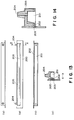
- Figure 1 is a schematic perspective view of an ink jet recording head.
- Figure 2 is a schematic view illustrating arrangement of a heater board for an ink jet recording head according to an embodiment of the present invention.
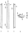
- Figure 3 is a schematic view illustrating a top plate of the ink jet recording head according to the embodiment of the present invention.
- Figure 4 illustrates a manufacturing step of the ink jet recording head according to the embodiment.
- Figure 5 is a schematic perspective view of an ink jet recording head according to the present invention.
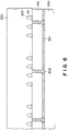
- Figure 6 is a schematic view illustrating a positional relationship between a heater board and a top plate of an ink jet recording head according to the present invention.
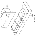
- Figure 7 is an exploded perspective view of an ink jet recording head according to the present invention.
- Figure 8 is an exploded perspective view of an ink jet recording head according to an embodiment of the present invention.
- Figure 9 illustrates an ink jet recording head of background art.
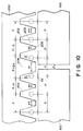
- Figure 10 illustrates a positional relationship between the heater board and a top plate.
- Figure 11 is a schematic view of a structure of a recording head of the background art.
- Figure 12 illustrates thermal behavior in the head of the background art.
- Figure 13 schematically illustrates a top plate used in this invention.
- Figure 14 is a schematic view illustrating a top plate used in this invention.
- Figure 15 schematically illustrates a top plate used in this invention.
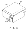
- Figure 16 schematically illustrates a head cartridge according to an embodiment of the present invention.
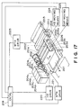
- Figure 17 illustrates a recording apparatus according to the present invention.
- Figure 18 illustrates a recording apparatus according to the present invention.
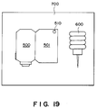
- Figure 19 illustrates an ink jet head kit according to an embodiment of the present invention.
- liquid is ink liquid, but the present invention is not limited to this.
- the recording means not only the recording of characters or letters or meaningful image, but includes meaningless patterns.
- the recording material may be, paper, plastic sheet, plastic plate, textile, strings, wood, leather, metal plate on which the ink can be applied by the recording head.
- the ink jet head has 3008 nozzles (printing width of 212 mm) at a density of 360 dpi (70.5 ⁇ m).
- a substrate (heater board) 100 has 128 ejection energy generating elements 101 thereon at predetermined positions at the density of 360 dpi.
- the element is in the form of a heat generating resistor for generating energy can be applied to the ink.
- the heater board is provided with signal pads for receiving external signals for driving the ejection energy generating elements 101 at proper timings and width electric energy supply pads 102 for supplying electric energy for driving the ejection energy generating elements 101.
- the heater board is also provided with function elements such as shift resister or the like functioning to output parallel signals to the ejection energy generating elements on the basis of serious input signals.
- Examples of the material of the substrate include monocrystal silicon, polycrystal silicon glass, metal or ceramic material in the form of a plate.
- the heater board 100 is bonded and fixed by adhesive material on a surface of a supporting member (base plate, 300 of aluminum, stainless steel or another metal or ceramic material).
- Figure 2 illustrates a state in which a plurality of heater boards 100 are disposed on one side of the base plate 300 with small gap between adjacent ones, into an array.
- the heater boards 100 are bonded and fixed by the adhesive material 301 applied with a predetermined thickness thereon at predetermined positions on the base plate 300.
- the gap between the adjacent heater boards may be as it is, if the ink does not leak, but in this embodiment, it is sealed with a sealant 302.
- the base plate 300 is provided with a wiring board 400 by an adhesive material, similarly to the heater board 100.
- a predetermined positional relationship is established between the pads 102 on the heater board 100 and the signal and electric energy supplying pads 401 on the wiring board.
- the wiring board is also provided with a connector 402 for supplying the external printing signals and driving electric energy.
- grooved top plate 200 The description will be made as to grooved top plate 200.
- the top plate 200 is provided with grooves 200 for constituting ink passages corresponding to ejection energy generating elements 101 on the heater boards 100 orifices 203 in fluid communication with the associated passages to eject the ink toward the recording material, a recess 201 for constituting a liquid chamber in fluid communication with the plurality of passages for supplying the ink to the passages 202, and an ink supply port 204 for receiving the ink from an ink container (not shown).
- the top plate 200 is long enough to cover all the ejection energy generating elements on the all of the heater boards 100 (a length corresponding to the array of the ejection energy generating elements).
- the top plate 200 shown in Figure 1 the top plate 200 is connected with the heater board in such a manner that a predetermined positional relationship is established between the passages 202 and the ejection energy generating elements 101 on the heater board 100 on the base plate 300.
- the material of the top plate 200 may be any, if the grooves can be formed correctly. Preferably, it has high mechanical strength, high dimensional stability and high durability against the ink. Examples of preferable materials include epoxy resin, acrylic resin, diglycol resin, dialkylcarbonate resin, unsaturated polyester resin, polyurethane resin, polyimide resin, melamine resin, phenol resin, urea resin materials. Particularly, polysalphon, polyethersalphon or the like is used because of the moldability and durability against the liquid.
- a plurality of heater boards 100 are bonded and connected with a predetermined dimensional relation.
- the above-described base plate is placed on a base 205 at a predetermined position, of a clamping machine (the entirety thereof is not shown).
- the position of the base plate is determined to be constant by pins on the base 205.
- the top plate 200 is placed on a hand 206 of the clamping or connecting machine.
- the top plate 200 is also placed on the hand 206 at the predetermined position, so that the positional relations therebetween are assured to a certain degree by placing the base plate 300 and the top plate 200 on the base 205 and the hand 206 in this manner.
- the positional relationship is checked with a microscope of the clamping machine.
- the 1504th heater 101 (one half of the number of ejection nozzles 3008) is checked in a direction A.
- the position is correctly determined for the heater in the direction A by the clamping machine, through image processing process.
- an orifice corresponding to the 1504th nozzle with checked in a direction B is adjusted in the direction X such that the position determined in the direction B is aligned with the position observed in the direction A.
- the position adjustment accuracy of the clamping machine is ⁇ 2 ⁇ m, and therefore, this accuracy is assured in the positioning in the direction X.
- the hand 206 is lowered in the direction Z while maintaining the positional accuracy, so that the top plate 200 is clamped on the heater board 100.
- the hand 206 is removed while pressing the top plate in the direction B (y), and then they are fixed together by a spring 500 ( Figure 5).
- the clamping method uses mechanical element such as spring, but another method is usable for example using an adhesive material alone or in combination with the spring.
- the top plate 200 and the heater board 100 are fixed with the relationship shown in Figure 6.
- the top plate 200 described in the foregoing may be manufactured through a known method such as, machining (cutting), molding, injection, photolithography or the like.
- a long grooved top plate is mounted on a head member having a plurality of heater boards each provided with a plurality of energy generating elements, more particularly, on one side of the base plate.
- the ink jet recording head To the ink jet recording head thus manufactured, the is supplied into the liquid passage through the liquid chamber constituted by the recess 201 of the top plate from the ink supply port 204.
- an electric signal is applied to an ejection energy generating element disposed corresponding to an associated passage, so that the ink is heated by the thermal energy produced by the ejection energy generating element.
- film boiling is produced in the ink with the result of creation of a bubble to provide a pressure to eject the ink through the ejection outlet (orifice) 203.
- 10 heater boards are used to provide 1280 ejection energy generating elements in the long head.
- the number of heater boards is not limiting, and it may be two or more.
- the ink supply system is simplified, downsized and in expensive, as compared with a plurality of small heads each having the top plate mounted on each heater board. Also, the manufacturing yield can be increased.
- the electric wiring can be simplified.
- a long top plate covering an array of energy generating elements provided by the plurality of heater boards is mounted on the base member, and therefore, the directions of the individual passages are uniform as contrasted to the case that small heads are arranged. Particularly when one top plate is used, the directions of all of the passages are aligned by one aligning operation, so that long head free of printing deviation, can be easily provided.
- the ink is ejected through an integral orifice plate, and the passages are also integral, so that the ejection and ejection directions are uniform, as if it is a single long head.
- top plates each covering a plurality of heater boards not all of the heater boards, may be used in the present invention, but use of the single top plate is most desirable.
- the top plate is provided with orifices (ejection holes) for ejecting the ink.
- orifices ejection holes
- the ink ejecting directions are determined by the top plate so that the high speed and high quality head can be most easily provided.
- the top plate is not provided with orifices, that is, even if the orifices are provided by the connection between the heater board and the grooved top plate, the directions of the ink passages can be aligned using the long top plate in this invention, and therefore, the stability of the ink ejection direction can be assured, which leads to satisfactory image printing.
- the top plate integrally having the orifices is better since the ejecting directions are aligned more accurately, and since the manufacturing steps are simplified.
- the gap between the adjacent heater boards is sealed by a sealant.
- the detailed description will be made as to the sealing for the gap.
- the heater boards When a plurality of heater boards are mounted on a support, the heater boards may be abutted to each other, but with this arrangement, the following problems arise.
- the flatness of the abutment surfaces of the heater boards have to be very high. If foreign matter is sandwiched therebetween, the positional accuracy is not enough.
- the heater board may be damaged by the abutment.
- the heater board may be deviated by thermal expansion.
- the heater boards are arranged with gap therebetween. However, in such a case, the following problems arise.
- the gap is sealed by a resin material ( Figures 6 and 7).
- Figure 8 shows such an ink jet recording head.
- the base plate 300 is provided with a guiding groove 7 in order to control the flowability of the silicone resin material curable at normal temperature to fill the gap between adjacent heater boards.
- the guiding groove preferably has a rectangular, square, V cross-section or the like.
- the design gap between adjacent heater boards is 16 ⁇ m, but actually it is 2 - 16 ⁇ m because of the cutting accuracy and the positioning accuracy of the heater boards.
- a heat curing dibon bonding layer of a thickness of several microns is provided through screen printing on the support 300.
- the silicone substrates of the heater boards have been the ones cut out of one and the same silicone wafer for the purpose of alignment with the accuracy of the height of ⁇ 1 ⁇ m.
- the gap between the heater boards is filled with silicone sealant (TSE 399, available from Toshiba Silicone Kabushiki Kaisha, Japan) by dropping 0.3 g to the rear side of the gap between the heater boards and using capillary force.
- TSE 399 available from Toshiba Silicone Kabushiki Kaisha, Japan
- the heater board and a PCB board already bonded on the base plate 300 are electrically connected through wire bonding. Thereafter, it is connected with a top plate 200 having grooves for constituting ink passages and having an ink ejection outlets, such that the grooves are in alignment with the associated energy generating elements, respectively. Then, the sealing and the connection with the ink container are carried out, and the ink jet recording head is manufactured.
- the actual printing operations are carried out using the thus produced ink jet recording head, satisfactory high quality printing was provided without missing part. Practically, there has not been any problems of ejection power leakage (crosstalk) of the ink at the end nozzles of each of the heater boards.
- the description will be made as to the manufacturing method for the ink jet head of Figure 8.
- the heater boards are disposed on the base plate 300 in the similar manner as in the foregoing embodiment with the exception that guiding grooves 7 shown in Figure 8 are formed on the base plate 300 with the cross-section of square (0.5 x 0.5 mm).
- the silicone sealant (TSE 399) used for the sealing of the gap between the heater boards first enters the gap between the heater boards, and then it enters the guiding groove.
- the silicone normal temperature curing resin material is cured before it fills the gap between the heater boards, as the case may be. According to the method of this embodiment, it never occurs, although 120 times were carried out. The reason for this considered as being that the sealant in the guiding groove is always supplied to the gap between the heater boards.
- the abutment portion is made smoother by the sealant, and therefore, better connection is accomplished.
- the sealant the known material used in the ink jet recording apparatus manufacturing or a semiconductor manufacturing, but it is preferably good in the electric insulation and elasticity and durability against ink.
- examples of such materials include silicone sealant or urethane sealant.
- the same sealant material is used for fixing the heater board and for between the adjacent heater boards.
- Figure 9 is a sectional view of a head constituted by connecting a top plate or member having grooves constituting the passages to the plurality of the heater boards on the support. Between the heater boards, there are gaps L, which are not uniform depending on the positional accuracies of the heater boards. If this occurs or if deviation occurs in the mounting position of the grooved member to the heater board, the passage opens to the gap, as indicated by a reference numeral 202, with the result of liability of release of the pressure to be used to eject the ink. The ejection performance of the ink through the ejection outlet adjacent the gap may be different from that of another gap. This may results in non-uniformity or unintended stripes in the recorded image.
- the gap is covered by a wall for constituting the passage.
- Figure 10 shows a relationship between the gaps and the top plate 200 in this embodiment.
- a wall thickness 206 providing the discrete passages 202 (a width at the contact surface with the base member in this embodiment) W3 is 20 ⁇ m.
- the wall thickness at the both sides W2 12 ⁇ m which is smaller. Therefore, the intervals between passages 202 is P, P- ⁇ , P+2 ⁇ , P- ⁇ and P, from the left side.
- the orifices 203 are arranged with an interval or pitch P corresponding to the interval between the ejection energy generating elements.
- the material of the top plate 200 is resin material
- the material of the base plate supporting the heater board is metal such as stainless steel or the like.
- FIG 11 there is shown a positional relationship between passages 106 of the ink jet head and ejection energy generating elements 101, wherein the ejection energy generating elements are substantially at the centers of the respective passages ( a nearly equal b).
- Reference numeral 1105 designates an ejection outlet, and a reference numeral 1101 is a wall for constituting the passage.
- the thermal expansion coefficient of the resin material constituting the top plate is approx. 1x10 ⁇ 5 - 1x10 ⁇ 4 approx.
- the following description will be made, taking polysulfone (thermal expansion coefficient: 56x10 ⁇ 6) as an example.
- the thermal expansion coefficient is 2.4x10 ⁇ 6, and the thermal expansion coefficient of the stainless steel used as the base plate 300 supporting the heater boards 100 is 17.3x10 ⁇ 6. Even if the recording head is correctly assembled under the temperature about 25 o C, the temperature of the recording head may probably increase to 60 o C by the operation thereof.
- the countermeasure is desirably taken against the thermal expansion.
- Figure 13 shows such an embodiment, wherein the grooved top plate is schematically shown, wherein (a) is a top plan view, (b) is a front view, (c) is a bottom plan view and (d) is a sectional view.
- the top plate 200 as shown in Figure 13, (d) which is X-X cross-section, a supporting member 205 capable of adjusting the thermal expansion coefficient of the top plate 200 is contained in the resin material constituting the groove portion of the top plate 200.
- the material of the supporting member 205 has the equivalent thermal expansion coefficient to that of the base plate 300.
- it is of stainless steel as in the base plate.
- the surface of the supporting member 205 has been subjected to a surface treatment such as blast process, knurling process, by which the contact with the resin part of the top plat 200 is further improved. With this structure, the thermal expansion coefficient of the top plate 200 is closer to that of the stainless steel. By doing so, the top plate 200 of the head and the base plate 300 thereof have the thermal expansion coefficient equivalent to each other, and therefore, no significant deviation occurs between the top plate 200 and the base plate.
- the supporting member 205 is within the resin material, but it is not necessarily completely contained therein, but a part (opposite ends, for example) may be exposed to the outside.
- the contactness of the resin material is improved by machining the surface of the supporting member 205, but if the contact between the supporting member and the resin part is good enough, this not inevitable.
- the top plate has been manufactured by injection molding while the supporting member is therein, but the sufficient contactness is not always assured by such an injection molding, and therefore, the surface roughness is preferably provided on the surface of the supporting member 205 to improve the contactness.
- grooves having approx. 1 mm may be directly machined, or when the core material is machined, the trace of the machining is deliberately retained, or the surface is roughened by sandblasting. In any case, biting occurs between the core material and the resin material so that the thermal expansion of the core material is closer to the resin material.
- the improvement of the contactness between the resin material and the supporting member may be accomplished by the provision of the surface roughness, or by applying a coupling material such as silane coupling material or the like on the supporting surface.
- a coupling material such as silane coupling material or the like
- the formation of the pits and projections as described above is preferable.
- the thickness of the resin material is preferably 2 mm or lower or further preferably 1.5 mm or lower from the supporting material.
- the stainless steel as in the base plate is used since it has the same thermal expansion coefficient as the base plate.
- the description will be made as to the example of the state of ejection performance of the liquid relating to the difference of the thermal expansion coefficient between the base plate and the supporting member.
- the base plate has to carry the heater boards, and has to be subjected to various machining for the purpose of coupling with the main assembly, and therefore, it is desired to have high machinability and heat radiation property to quickly release the heat coming from the heater board.
- the aluminum is used.
- stainless steel is used in consideration of the contactness with the polysulfone resin and the mechanical strength.
- the temperature when the head is assembled is 25 o C, and the temperature difference is based on this temperature.
- the temperature of the recording nozzle is usually controlled to 35 o C - 40 o C.
- the printing rate is high, when a long term printing is carried out, or when the ambient temperature increases, the temperature of the head in some cases reached 50 o C.
- the printing operation is stopped before the temperature reaches 60 o C. Therefore, the printing at this temperature is not practical.
- the ambience in which the head is kept is 60 o C at the highest, and the data at this temperature are also given.
- the problems are all resulted from the positional relationship between the nozzle and heater.
- the nozzle pitch (heater pitch) is 70.5 mm, and the nozzle width is 50 ⁇ m. If the deviation between the groove of the top plate and the heater position is not more than 10 ⁇ m, the ejection performance is not at all influenced. If it is larger and not larger than 20 ⁇ m, slight deterioration is observed but practically not a problem.
- the thermal expansion coefficient difference (25 o C - 50 o C) is less than 10x10 ⁇ 6 between the base plate and the supporting member. Further preferably, it is not larger than 2.6x10 ⁇ 6.
- the base plate may be of stainless steel, aluminum, ceramic material, resin material or the like
- the supporting material may be of stainless steel, aluminum, ceramic material, glass material or the like, if they are equivalent within the range above-described.
- the base plate is of aluminum material
- the supporting material is stainless steel materials.
- Figure 14 shows a further embodiment of the top plate 200. It shows only X-X section of Figure 13.
- the same reference numerals 201 - 205 are assigned for the same elements.
- the supporting member 205 occupies most part of the inside of the top plate, having a channel-like cross-section. By doing so, the mechanical rigidity of the supporting member 206 is significantly increased, the curving due to the temperature coefficient difference between the resin part and the supporting member can be avoided.
- the thermal expansion coefficient of the liquid chamber portion can be adjusted in addition to the liquid passage portions, and therefore, the deformation of the liquid chamber is small, so that the recording head is durable in long term use.
- Figure 15 shows a further embodiment of the top plate.
- the supporting member 205 in Figure 15 is in the form of a pipe, and the opposite end portions thereof are projected beyond the top plate.
- the pipe is provided with a slit to permit fluid communication between the inside of the pipe and the liquid chamber 201.
- the pipe of the supporting member 205 may be used as the liquid chamber.
- the end portions thereof are usable as ink supply joint.
- the slit 206 may be replaced with perforations having proper intervals. By doing so, the mechanical rigidity of the supporting member 205 can be significantly increased.
- the supporting member is required to have the rigidity as the supporting member and anti-corrosion property against ink.
- acidic alkaline ink is widely used, and therefore, it is required to have durability against the material.
- the cost is low.
- examples of such materials include aluminum alloy or stainless steel.
- aluminum alloys include A505, A506, A6061, A6063 or the like which have anti-corrosion property.
- Examples of stainless steels include SUS 303, 304, 430 or 420. From the standpoint of machinability and cost, aluminum alloy is preferable, but stainless steel is preferable from the durability against ink.
- one side of the supporting member is effective to constitute a part of the common liquid chamber.
- the grooved member (top plate) contains a supporting member having an equivalent thermal expansion coefficient to that of the base plate, it can be avoided that the deviation occurs between the ejection energy generating element and the nozzle positions due to the thermal expansion difference upon temperature rise as a result of the external ambience change or the operation of the recording head, and therefore, high quality printing can be assured at any temperature.
- a pipe-like supporting member By using a pipe-like supporting member, it can be used as also an ink supply pipe, thus the number of parts can be reduced, so that the cost of the head can be further reduced.
- FIG 16 shows an ink jet cartridge using such an ink jet head.
- the ink jet head cartridge comprises an ink jet head 500 and an ink container 501 for containing ink to be supplied to the ink jet recording head, which is integral or separable relative to the ink jet head 500.
- an ink jet cartridge having the above-described advantageous effects can be provided.
- the ink is supplied into the ink container. When the ink refilled is contained, the service life of the head cartridge is extended, so that the running cost can be reduced.
- Figure 17 shows an example of an ink jet recording apparatus incorporating the ink jet recording head according to an embodiment of the present invention.
- the ink jet recording apparatus is provided with line-type heads 201a - 201d.
- the line type heads 201a - 201d are fixed to be extended in parallel with each other with a predetermined gap in X direction by a holder 202.
- ejection outlets are provided directed downward and arranged in one line at the density of 16 ejection outlets per 1 mm. This permits the recording on the width of 218 mm.
- Each of the recording heads is a type of using thermal energy, and the ejection is controlled by a head driver 220 (driving signal supplying means).
- a head unit is constituted by heads and a holder 202.
- the head unit is movable up and down by head moving means 224.
- head cap 203a - 203d are disposed adjacent to each other and corresponding to the associated heads 201a - 201d.
- ink absorbing materials such as sponge material are provided in the head caps 203a - 203d.
- the caps 203a - 203d are fixed by an unshown holder, and the capping unit includes the holder and the caps 203a and 203d.
- the cap unit is movable in X direction by a cap moving means 225.
- Each of the recording heads 201a - 201d is supplied with either of cyan, magenta, yellow and black color ink through the associated ink supply tube 205a - 205d from the associated ink container 204a - 204d to permit color recording.
- the ink supply uses capillary force of the head ejection outlet, and the liquid surface level in each of the ink containers 204a - 204d is lower than a predetermined amount than the ejection outlet position.
- the apparatus is provided with an electrically chargeable seamless belt 204 for carrying a recording sheet 227 (recording material).
- the belt is extended through a predetermined path around a driving roller 207, idler rollers 209, 209a and a tension roller 210.
- the belt is rotated by a belt driving motor 208 connected to the driving roller 207 and driven by a motor driver 221.
- the belt 206 travels in the direction X immediately below the ejection outlets of the heads 201a - 201d. Here, the downward deviation is suppressed by the fixing member 226.
- Designated by a reference numeral 217 is a cleaning unit for removing paper dust or the like from the surface of the belt 202.
- the recording apparatus is usable for textile printing, a textile printing system including pre-process including fixing, or post-processing, and a copying machine having a reading device.
- Figure 18 shows a recording apparatus having a recording head with two or the like heater boards.
- an ink jet recording head cartridge having an ink container 901 and a recording head 902 detachably mountable therefrom carried on a carriage AC, and comprises a motor 903 as a driving source for driving feeding rollers or the like for feeding the recording material 800, a carriage 904 for transmitting the driving force from the driving source to the carriage. It further comprises a signal supplying means for supplying signal for ejecting the ink to the ink jet recording head.
- Figure 19 schematically shows an ink jet head kit 700 of this invention. It comprises an ink jet head 500, an ink container 501 integral or separable relative to the head 500, and ink filling means 600 for filling the ink into the ink container.
- ink jet head kit Using such an ink jet head kit, the running cost of the ink jet head can be reduced. The description will be made as to the ink filling method using the ink jet head kit.
- a part of the ink filling means is inserted through an air bent 510 of the ink container, a connecting portion relative to the head and a hole formed in the ink container from which the ink is used up, and the ink is supplied into the ink container.
- An ink jet recording head for effecting recording with ejection of ink includes a plurality of element substrates each having a plurality of ejection energy generating elements for ejecting the ink; a base plate for supporting the plurality of element substrates on one surface thereof in an array; a grooved member having a length corresponding to a length of the array and having passages corresponding to the ejection energy generating elements of the plurality of element substrates.
Abstract
Description
- The present invention relates to liquid jet head, an ink jet recording head using ink as the liquid, an ink jet head cartridge having the ink jet head, an ink jet recording apparatus, more particularly to the ink jet recording head, the ink jet head cartridge using the same, and an ink jet head kit, and an ink jet recording apparatus, in which the recording head is elongated having a plurality of substrate having ejection energy generating elements. The present invention also relates to a manufacturing method for the ink jet head. Additionally, it relates to a method of injecting the ink into an ink container.
- The present invention is applicable not only to a printer used in an office, or a printer for textile printing.
- A recording apparatus such as a printer, copying machine or facsimile machine, is so constructed that on the basis of image information, an image of dot pattern is formed on a recording material such as paper, plastic thin plate, textile or the like.
- The recording apparatus can be classified, on the basis of the recording system, an ink jet type, a wire dot type, a thermal type, an electrophotographic type or the like. Among them, an ink jet type (ink jet printing apparatus) is constructed such that recording liquid (ink) droplet is ejected through an ejection outlet of an ink jet recording head onto a recording material.
- The ink jet type has the advantages that the high speed recording is possible with low nozzle, that a wide range of recording materials are usable, and that the color image recording is easily accomplished, and therefore, it is widely used recently.
- Among the ink jet type, a thermal ink ejecting type recording head using pressure resulting from thermal expansion produced by application of thermal energy to the ink, is advantageous in that the responsivity to the recording signal is high that the density of the ejection outlets can be increased without difficulty.
- In the thermal energy ink ejection type, it is particularly expected from the standpoint of the high speed recording that a long full-line type recording head (full-line recording head) covering an entire width of the recording material by having ejection outlets and corresponding electrothermal transducers (ejection energy generating elements). However, in the manufacturing of such a line recording head, it has been very difficult to manufacture it without any defect in the ejection energy generating element all over the entire width of the recording area.
- More particularly, in the case of a line recording head covering A3 size recording sheet at the density of 400 dpi (dot per inch), 4736 ejection energy elements a pair of electrodes and a heat generating resistor therebetween (in the case of the thermal ink ejection type) have to be provided without any one defect, which is very difficult. Therefore, the head cost is very high with the result of difficulty putting it into practice.
- Heretofore, various proposals have been made.
- For example, Japanese Laid-Open Patent Applications Nos. 132253/1980, 2009/1990, 229278/1992, 232749/1992, 24192/1993, have proposed that relatively easily manufacturable heads having 32, 48, 64 and 128 ejection outlets, are connected on the top and bottom surface one supporting member with high precision in according with the nozzles density.
- More particularly, the recording heads are disposed in a stack as manner on the opposite surfaces of the supporting material to provide one long ink jet head. With this method, the relatively small heads are disposed on the opposite surfaces of the supporting member, and therefore, there exist a marginal area on each side. For this reason, the heads can be relatively easily mounted by head mounting means so that there is a relatively high latitude in the design of the head arrangement. However, in the recording head of this structure, the electric signals required for driving the head and the ink to be ejected, have to be supplied to both sides of the supporting member, with the result of very high manufacturing cost. In addition, the size of the ink jet head is large because small heads are disposed on the both sides of the supporting member. Additionally, each part, particularly the supporting member for the small heads, is required to be very high accuracy in the flatness on each side, the parallelism between the sides, the distance between the surfaces, with the result of very high cost.
- In another method, a plurality of small heads as disclosed in Japanese Laid-Open Patent Application No. 229278/1992 are disposed on one side of the substrate to provide an elongated head. With this method, the above-described drawbacks are partly removed. However, with respect to the ink supply system, the ink has still to be supplied to the individual small heads with the result of high cost. What is more difficult is that the ink leakage has to be prevented at both sides of the small heads. In this long head, the small heads are arranged without changing the nozzle pitch, and therefore, at the opposite sides of a small head, the tolerance thereat is less than only one half the nozzle pitch. For example, when the nozzle pitch corresponds to 400 dpi (63.5 µm), the distance between the center of the end nozzle and the side surface is required to be not more than 63.5/2 = 30 µm. This includes one half of the nozzle width. If it is 12 µm, the rest is less than 18 µm. What is requires is to seal for preventing the ink leakage with this dimension, which is highly difficult with the result of very high manufacturing cost of the recording head.
- The foregoing is the explanation of the problems with the manufacturing for the two types of the recording heads. From this standpoint of designing, the following problems are involved. In both of the types, a plurality of small heads are arranged, and therefore, the small heads are positioned with tolerance with the result of small difference in the ink ejecting directions (front-back, left-right, and angular deviations). This may result in non-uniform printing as a hole of the ink jet head. Amounts of ink ejected are also slightly different, which may result in printing non-uniformity. Therefore in order to provide high quality image, the individual heads are exchanged through trial and error to finally provided one satisfactory long head. This also increases the cost.
- Accordingly, it is a principal object of the present invention to provide a small size and inexpensive recording apparatus capable of effecting high speed and high quality printing.
- It is another object of the present invention to provide an ink jet head manufacturing method for manufacturing an ink jet head with high yield and low cost.
- It is another object of the present invention to provide a small size inexpensive ink jet head capable of effecting printing with high quality and high speed.
- It is a further object of the present invention to provide an ink jet head kit and an ink refilling method into an ink container, by which the ink jet head can be repeatedly usable by refilling ink, so that the running cost can be reduced.
- According to an aspect of the present invention, there is provided an ink jet recording head for effecting recording with ejection of ink comprising: a plurality of element substrates each having a plurality of ejection energy generating elements for ejecting the ink; a base plate for supporting the plurality of element substrates on one surface thereof in an array; a grooved member having a length corresponding to a length of the array and having passages corresponding to the ejection energy generating elements of the plurality of element substrates.
- According to another aspect of the present invention, there is provided a liquid ejection recording head for ejecting liquid comprising: a plurality of element substrates each having a plurality of ejection energy generating elements for ejecting the liquid; a base plate for supporting the plurality of element substrates on one surface thereof in an array; a grooved member having a length corresponding to a length of the array and having passages corresponding to the ejection energy generating elements of the plurality of element substrates.
- According to a further aspect of the present invention, there is provided an ink jet recording apparatus for effecting recording with ejection of ink comprising: an ink jet recording head for effecting recording with ejection of ink including a plurality of element substrates each having a plurality of ejection energy generating elements for ejecting the ink; a base plate for supporting the plurality of element substrates on one surface thereof in an array; a grooved member having a length corresponding to a length of the array and having passages corresponding to the ejection energy generating elements of the plurality of element substrates; and driving signal supplying means for supplying a driving signal for driving the ejection energy generating elements.
- According to a yet further aspect of the present invention, there is provided an ink jet head kit comprising: an ink jet recording head for effecting recording with ejection of ink including a plurality of element substrates each having a plurality of ejection energy generating elements for ejecting the ink; a base plate for supporting the plurality of element substrates on one surface thereof in an array; a grooved member having a length corresponding to a length of the array and having passages corresponding to the ejection energy generating elements of the plurality of element substrates; an ink container for containing ink to be supplied to the ink jet recording head; and ink filling means for filling the ink to the ink container.
- According to a further aspect of the present invention, there is provided an ink jet head manufacturing method comprising the steps of: a step of arranging a plurality of element substrates each having a plurality of ejection energy generating elements on a base member; a step of coupling, with the plurality of element substrates, a grooved member having a length corresponding to an array of the plurality of element substrates and having the plurality of grooves for constituting passages corresponding to the ejection energy generating elements.
- According to a yet further aspect of the present invention, convenient ink filling method is provided.
- According to an aspect of the present invention, the necessity for using one long recording head involving low yield, is eliminated, and high yield heads having 64 or 128 ejection energy generating elements are usable, and therefore, the yield of the recording heads and the low cost manufacturing are accomplished. Additionally, even if a plurality of substrates are used, the grooved member is common, and therefore, the directions of the passage and the ejection outlets are made uniform as compared with the structure using small heads each having the substrate and the top plate, and therefore, a long head capable of providing good images can be manufactured with low cost.
- These and other objects, features and advantages of the present invention will become more apparent upon a consideration of the following description of the preferred embodiments of the present invention taken in conjunction with the accompanying drawings.
- Figure 1 is a schematic perspective view of an ink jet recording head.
- Figure 2 is a schematic view illustrating arrangement of a heater board for an ink jet recording head according to an embodiment of the present invention.
- Figure 3 is a schematic view illustrating a top plate of the ink jet recording head according to the embodiment of the present invention.
- Figure 4 illustrates a manufacturing step of the ink jet recording head according to the embodiment.
- Figure 5 is a schematic perspective view of an ink jet recording head according to the present invention.
- Figure 6 is a schematic view illustrating a positional relationship between a heater board and a top plate of an ink jet recording head according to the present invention.
- Figure 7 is an exploded perspective view of an ink jet recording head according to the present invention.
- Figure 8 is an exploded perspective view of an ink jet recording head according to an embodiment of the present invention.
- Figure 9 illustrates an ink jet recording head of background art.
- Figure 10 illustrates a positional relationship between the heater board and a top plate.
- Figure 11 is a schematic view of a structure of a recording head of the background art.
- Figure 12 illustrates thermal behavior in the head of the background art.
- Figure 13 schematically illustrates a top plate used in this invention.
- Figure 14 is a schematic view illustrating a top plate used in this invention.
- Figure 15 schematically illustrates a top plate used in this invention.
- Figure 16 schematically illustrates a head cartridge according to an embodiment of the present invention.
- Figure 17 illustrates a recording apparatus according to the present invention.
- Figure 18 illustrates a recording apparatus according to the present invention.
- Figure 19 illustrates an ink jet head kit according to an embodiment of the present invention.
- In the following description, the liquid is ink liquid, but the present invention is not limited to this.
- In this invention, the recording means not only the recording of characters or letters or meaningful image, but includes meaningless patterns.
- The recording material may be, paper, plastic sheet, plastic plate, textile, strings, wood, leather, metal plate on which the ink can be applied by the recording head.
- Referring to Figure 1, there is shown major parts of an ink jet head according to an embodiment of the present invention. In this embodiment, the ink jet head has 3008 nozzles (printing width of 212 mm) at a density of 360 dpi (70.5 µm).
- A substrate (heater board) 100 has 128 ejection
energy generating elements 101 thereon at predetermined positions at the density of 360 dpi. In this embodiment, the element is in the form of a heat generating resistor for generating energy can be applied to the ink. The heater board is provided with signal pads for receiving external signals for driving the ejectionenergy generating elements 101 at proper timings and width electricenergy supply pads 102 for supplying electric energy for driving the ejectionenergy generating elements 101. The heater board is also provided with function elements such as shift resister or the like functioning to output parallel signals to the ejection energy generating elements on the basis of serious input signals. - Examples of the material of the substrate include monocrystal silicon, polycrystal silicon glass, metal or ceramic material in the form of a plate.
- The
heater board 100 is bonded and fixed by adhesive material on a surface of a supporting member (base plate, 300 of aluminum, stainless steel or another metal or ceramic material). - Figure 2 illustrates a state in which a plurality of
heater boards 100 are disposed on one side of thebase plate 300 with small gap between adjacent ones, into an array. Theheater boards 100 are bonded and fixed by theadhesive material 301 applied with a predetermined thickness thereon at predetermined positions on thebase plate 300. The heater boards are bonded with such a high accuracy that an interval between adjacent end ejection energy generating elements of adjacent heater boards is substantially equal to the interval between adjacent ejection energy generating elements within the heater board 100 (P = 70.5 µm). The gap between the adjacent heater boards may be as it is, if the ink does not leak, but in this embodiment, it is sealed with asealant 302. - In Figure 1, the
base plate 300 is provided with awiring board 400 by an adhesive material, similarly to theheater board 100. A predetermined positional relationship is established between thepads 102 on theheater board 100 and the signal and electricenergy supplying pads 401 on the wiring board. The wiring board is also provided with aconnector 402 for supplying the external printing signals and driving electric energy. - The description will be made as to grooved
top plate 200. - As shown in Figure 3, the
top plate 200 is provided withgrooves 200 for constituting ink passages corresponding to ejectionenergy generating elements 101 on theheater boards 100orifices 203 in fluid communication with the associated passages to eject the ink toward the recording material, arecess 201 for constituting a liquid chamber in fluid communication with the plurality of passages for supplying the ink to thepassages 202, and anink supply port 204 for receiving the ink from an ink container (not shown). Thetop plate 200 is long enough to cover all the ejection energy generating elements on the all of the heater boards 100 (a length corresponding to the array of the ejection energy generating elements). - In this invention, the
top plate 200 shown in Figure 1, thetop plate 200 is connected with the heater board in such a manner that a predetermined positional relationship is established between thepassages 202 and the ejectionenergy generating elements 101 on theheater board 100 on thebase plate 300. The material of thetop plate 200 may be any, if the grooves can be formed correctly. Preferably, it has high mechanical strength, high dimensional stability and high durability against the ink. Examples of preferable materials include epoxy resin, acrylic resin, diglycol resin, dialkylcarbonate resin, unsaturated polyester resin, polyurethane resin, polyimide resin, melamine resin, phenol resin, urea resin materials. Particularly, polysalphon, polyethersalphon or the like is used because of the moldability and durability against the liquid. - The description will be made as to the connection between the top plate and the support for the heater boards.
- On the
base plate 300, a plurality ofheater boards 100 are bonded and connected with a predetermined dimensional relation. - Subsequently, as shown in Figure 4, the above-described base plate is placed on a base 205 at a predetermined position, of a clamping machine (the entirety thereof is not shown). The position of the base plate is determined to be constant by pins on the
base 205. Subsequently, thetop plate 200 is placed on ahand 206 of the clamping or connecting machine. Thetop plate 200 is also placed on thehand 206 at the predetermined position, so that the positional relations therebetween are assured to a certain degree by placing thebase plate 300 and thetop plate 200 on thebase 205 and thehand 206 in this manner. Subsequently, the positional relationship is checked with a microscope of the clamping machine. First, the 1504th heater 101 (one half of the number of ejection nozzles 3008) is checked in a direction A. In other words, the position is correctly determined for the heater in the direction A by the clamping machine, through image processing process. Then, an orifice corresponding to the 1504th nozzle with checked in a direction B. The positional relation is adjusted in the direction X such that the position determined in the direction B is aligned with the position observed in the direction A. - The position adjustment accuracy of the clamping machine is ±2 µm, and therefore, this accuracy is assured in the positioning in the direction X. Subsequently, the
hand 206 is lowered in the direction Z while maintaining the positional accuracy, so that thetop plate 200 is clamped on theheater board 100. Thehand 206 is removed while pressing the top plate in the direction B (y), and then they are fixed together by a spring 500 (Figure 5). - In this embodiment, the clamping method uses mechanical element such as spring, but another method is usable for example using an adhesive material alone or in combination with the spring. In any event, the
top plate 200 and theheater board 100 are fixed with the relationship shown in Figure 6. - The
top plate 200 described in the foregoing may be manufactured through a known method such as, machining (cutting), molding, injection, photolithography or the like. - As described in the foregoing, a long grooved top plate is mounted on a head member having a plurality of heater boards each provided with a plurality of energy generating elements, more particularly, on one side of the base plate. To the ink jet recording head thus manufactured, the is supplied into the liquid passage through the liquid chamber constituted by the
recess 201 of the top plate from theink supply port 204. For the ink ejection, an electric signal is applied to an ejection energy generating element disposed corresponding to an associated passage, so that the ink is heated by the thermal energy produced by the ejection energy generating element. By the heat, film boiling is produced in the ink with the result of creation of a bubble to provide a pressure to eject the ink through the ejection outlet (orifice) 203. - In this embodiment, 10 heater boards are used to provide 1280 ejection energy generating elements in the long head. However, the number of heater boards is not limiting, and it may be two or more.
- With this structure, the ink supply system is simplified, downsized and in expensive, as compared with a plurality of small heads each having the top plate mounted on each heater board. Also, the manufacturing yield can be increased. In addition, since a plurality of heater boards are disposed on one side of the base plate, the electric wiring can be simplified. In addition, a long top plate covering an array of energy generating elements provided by the plurality of heater boards, is mounted on the base member, and therefore, the directions of the individual passages are uniform as contrasted to the case that small heads are arranged. Particularly when one top plate is used, the directions of all of the passages are aligned by one aligning operation, so that long head free of printing deviation, can be easily provided.
- Thus, the ink is ejected through an integral orifice plate, and the passages are also integral, so that the ejection and ejection directions are uniform, as if it is a single long head.
- When a small head are used, there is a necessity for effecting sealing for each small head. However, in this embodiment, the since the top plate covers a plurality of heater boards, the number of sealings is small.
- Particularly when, only one top plate is used, one sealing is enough a plurality of top plates each covering a plurality of heater boards not all of the heater boards, may be used in the present invention, but use of the single top plate is most desirable.
- In this embodiment, the top plate is provided with orifices (ejection holes) for ejecting the ink. This is preferable because the ink ejecting directions are determined by the top plate so that the high speed and high quality head can be most easily provided. Even if the top plate is not provided with orifices, that is, even if the orifices are provided by the connection between the heater board and the grooved top plate, the directions of the ink passages can be aligned using the long top plate in this invention, and therefore, the stability of the ink ejection direction can be assured, which leads to satisfactory image printing. However, the top plate integrally having the orifices is better since the ejecting directions are aligned more accurately, and since the manufacturing steps are simplified.
- In this embodiment, the gap between the adjacent heater boards is sealed by a sealant. The detailed description will be made as to the sealing for the gap. When a plurality of heater boards are mounted on a support, the heater boards may be abutted to each other, but with this arrangement, the following problems arise. The flatness of the abutment surfaces of the heater boards have to be very high. If foreign matter is sandwiched therebetween, the positional accuracy is not enough. The heater board may be damaged by the abutment. The heater board may be deviated by thermal expansion. In order to prevent this, in this invention, the heater boards are arranged with gap therebetween. However, in such a case, the following problems arise.
- (1) By the provision of the gap, the ink is easily leaked at the bottom of the passage at the end portions of the unit, and upon the ink ejection, the ink enters the gap with the result of crosstalk at the end portions.
- (2) The ink enters the gap between the protection film or the like resulted from cutting or the like of the unit end with the result of electric corrosion.
- Such liabilities arise. In view of this, in this embodiment, the gap is sealed by a resin material (Figures 6 and 7).
- Figure 8 shows such an ink jet recording head. In this Figure, the same reference numerals as in Figure 7 are assigned to the corresponding elements. In this example, the
base plate 300 is provided with a guiding groove 7 in order to control the flowability of the silicone resin material curable at normal temperature to fill the gap between adjacent heater boards. The guiding groove preferably has a rectangular, square, V cross-section or the like. - The description will be made as to the manufacturing method of the ink jet recording head shown in Figures 7 and 8.
- In this embodiment, in order to provide a 360 dpi ink jet recording head for a line printer for A4 size. 24 boards each having patterned 128 energy generating elements 12 at 360 dpi, are disposed on aluminum base plate 3, as shown in Figure 7.
- They are correctly aligned using image processing such that the interval between adjacent energy generating elements of adjacent heater boards, are equal to the interval between the adjacent energy generating element within one heater board. The design gap between adjacent heater boards is 16 µm, but actually it is 2 - 16 µm because of the cutting accuracy and the positioning accuracy of the heater boards.
- Immediately before arranging the heater boards on the
support 300, a heat curing dibon bonding layer of a thickness of several microns is provided through screen printing on thesupport 300. The silicone substrates of the heater boards have been the ones cut out of one and the same silicone wafer for the purpose of alignment with the accuracy of the height of ±1 µm. - After the bonding layer is cured, the gap between the heater boards is filled with silicone sealant (TSE 399, available from Toshiba Silicone Kabushiki Kaisha, Japan) by dropping 0.3 g to the rear side of the gap between the heater boards and using capillary force. In this manner, a first substrate is provided in this embodiment.
- Then, the heater board and a PCB board already bonded on the
base plate 300 are electrically connected through wire bonding. Thereafter, it is connected with atop plate 200 having grooves for constituting ink passages and having an ink ejection outlets, such that the grooves are in alignment with the associated energy generating elements, respectively. Then, the sealing and the connection with the ink container are carried out, and the ink jet recording head is manufactured. When the actual printing operations are carried out using the thus produced ink jet recording head, satisfactory high quality printing was provided without missing part. Practically, there has not been any problems of ejection power leakage (crosstalk) of the ink at the end nozzles of each of the heater boards. - The description will be made as to the manufacturing method for the ink jet head of Figure 8. The heater boards are disposed on the
base plate 300 in the similar manner as in the foregoing embodiment with the exception that guiding grooves 7 shown in Figure 8 are formed on thebase plate 300 with the cross-section of square (0.5 x 0.5 mm). - With this guiding groove, the silicone sealant (TSE 399) used for the sealing of the gap between the heater boards, first enters the gap between the heater boards, and then it enters the guiding groove.
- In the method not using the guiding groove, the silicone normal temperature curing resin material is cured before it fills the gap between the heater boards, as the case may be. According to the method of this embodiment, it never occurs, although 120 times were carried out. The reason for this considered as being that the sealant in the guiding groove is always supplied to the gap between the heater boards.
- Therefore, the advantageous effects of the guiding groove is very significant. The printing quality is high enough by this line type printer ink jet recording head (A4 size).
- In this embodiment, even if there is a step formed at the connecting portion between the adjacent heater boards, the abutment portion is made smoother by the sealant, and therefore, better connection is accomplished.
- As the sealant, the known material used in the ink jet recording apparatus manufacturing or a semiconductor manufacturing, but it is preferably good in the electric insulation and elasticity and durability against ink. Examples of such materials, include silicone sealant or urethane sealant.
- When the gap between the adjacent heater board is very small, the same sealant material is used for fixing the heater board and for between the adjacent heater boards.
- In this embodiment, the description will be made as to the structure for covering the gap between the heater boards by a wall of the top plate.
- When a plurality of substrates are successively placed on the same surface of a support in the manufacturing of the recording head, it is desirable that a small gap is provided between adjacent heater boards, as described hereinbefore in consideration of the positional accuracy of the substrates on the support, and the difference in the thermal expansion between the support and the substrate or heater board.
- Figure 9 is a sectional view of a head constituted by connecting a top plate or member having grooves constituting the passages to the plurality of the heater boards on the support. Between the heater boards, there are gaps L, which are not uniform depending on the positional accuracies of the heater boards. If this occurs or if deviation occurs in the mounting position of the grooved member to the heater board, the passage opens to the gap, as indicated by a
reference numeral 202, with the result of liability of release of the pressure to be used to eject the ink. The ejection performance of the ink through the ejection outlet adjacent the gap may be different from that of another gap. This may results in non-uniformity or unintended stripes in the recorded image. - In this embodiment, the gap is covered by a wall for constituting the passage.
- Figure 10 shows a relationship between the gaps and the
top plate 200 in this embodiment. - The dimensional accuracy of the heater board is ±2 µm relative to its absolute position, and the dimensional accuracy of the length of the heater board per se is 1±5 µm. These values are from the apparatuses of highest performance available at present. It is difficult to increase the accuracy more at present. Therefore, the tolerance is


board end elements 101 are disposed with an interval of P = 70.5 µm with the gap therebetween to provide the same interval within the heater board. On the other hand, thetop plate 200 faced to the base member hasgrooves 202 for constituting the passages with the interval P = 70.5 µm. Awall thickness 206 providing the discrete passages 202 (a width at the contact surface with the base member in this embodiment) W3 is 20 µm. However, the width of thewall 206 corresponding to the gap between the heater boards is expanded to W1 = 36 µm. In other words, thepassages 202 sandwiching the gap is deviated by α (α = 8 µm). By doing so, the wall thickness at the both sides W2 = 12 µm which is smaller. Therefore, the intervals betweenpassages 202 is P, P-α, P+2α, P-α and P, from the left side. As indicated by broken line, theorifices 203 are arranged with an interval or pitch P corresponding to the interval between the ejection energy generating elements. - By using the above-described structure described hereinbefore for the wall of the top plate, it is possible to cover the gap by the wall thickness W1 = 36 µm which is larger than the gap L which is 28 µm (L = 14 + 14) at the maximum as a result of manufacturing tolerance. Actually, there is an error when the top plate is aligned with the heater boards (usually ±4 µm approx.), the gap can be covered thereby sufficiently even if this error is included. With this structure, even if there is a gap between adjacent heater boards, the gap can be covered to prevent thee liability of leakage of the ejection pressure for ejecting the ink.
- A further embodiment of the present invention will be described.
- In the foregoing embodiments, the material of the
top plate 200 is resin material, and the material of the base plate supporting the heater board is metal such as stainless steel or the like. - In Figure 11, there is shown a positional relationship between passages 106 of the ink jet head and ejection
energy generating elements 101, wherein the ejection energy generating elements are substantially at the centers of the respective passages (a nearly equal b).Reference numeral 1105 designates an ejection outlet, and areference numeral 1101 is a wall for constituting the passage. When a long head having 3008 nozzles in such an ink jet head is used to effect the recording, or when the recording is effected under very high temperature ambience or under a very low temperature ambience, there is a liability that, as shown schematically in Figure 12, the positional relationship between the passage and the ejection energy generating element may be deviated due to the difference between the thermal expansion coefficients of the base plate and the top plate at the end of the heads. - The thermal expansion coefficient of the resin material constituting the top plate is approx. 1x10⁻⁵ - 1x10⁻⁴ approx. The following description will be made, taking polysulfone (thermal expansion coefficient: 56x10⁻⁶) as an example. When silicon is used for the
heater board 100, the thermal expansion coefficient is 2.4x10⁻⁶, and the thermal expansion coefficient of the stainless steel used as thebase plate 300 supporting theheater boards 100 is 17.3x10⁻⁶. Even if the recording head is correctly assembled under the temperature about 25 oC, the temperature of the recording head may probably increase to 60 oC by the operation thereof. - Assuming that the long head has 3008 nozzles, the following deviation occurs:

- Therefore, when the number of ejection outlets is very large, or when the recording head is used under special temperature conditions, the countermeasure is desirably taken against the thermal expansion.
- Figure 13 shows such an embodiment, wherein the grooved top plate is schematically shown, wherein (a) is a top plan view, (b) is a front view, (c) is a bottom plan view and (d) is a sectional view.
- The
top plate 200, as shown in Figure 13, (d) which is X-X cross-section, a supportingmember 205 capable of adjusting the thermal expansion coefficient of thetop plate 200 is contained in the resin material constituting the groove portion of thetop plate 200. Here, the material of the supportingmember 205 has the equivalent thermal expansion coefficient to that of thebase plate 300. In this embodiment, it is of stainless steel as in the base plate. The surface of the supportingmember 205 has been subjected to a surface treatment such as blast process, knurling process, by which the contact with the resin part of thetop plat 200 is further improved. With this structure, the thermal expansion coefficient of thetop plate 200 is closer to that of the stainless steel. By doing so, thetop plate 200 of the head and thebase plate 300 thereof have the thermal expansion coefficient equivalent to each other, and therefore, no significant deviation occurs between thetop plate 200 and the base plate. - There is also a thermal expansion difference between the
single heater board 100 and the top plate, but the deviation is so small that the ejection performance is not influenced. - In this embodiment, the supporting
member 205 is within the resin material, but it is not necessarily completely contained therein, but a part (opposite ends, for example) may be exposed to the outside. - In this embodiment, the contactness of the resin material is improved by machining the surface of the supporting
member 205, but if the contact between the supporting member and the resin part is good enough, this not inevitable. However, the top plate has been manufactured by injection molding while the supporting member is therein, but the sufficient contactness is not always assured by such an injection molding, and therefore, the surface roughness is preferably provided on the surface of the supportingmember 205 to improve the contactness. - To provide pits and projections for the purpose of providing the surface roughness, grooves having approx. 1 mm may be directly machined, or when the core material is machined, the trace of the machining is deliberately retained, or the surface is roughened by sandblasting. In any case, biting occurs between the core material and the resin material so that the thermal expansion of the core material is closer to the resin material.
- The improvement of the contactness between the resin material and the supporting member, may be accomplished by the provision of the surface roughness, or by applying a coupling material such as silane coupling material or the like on the supporting surface. However, in consideration of the influence to the ink, the formation of the pits and projections as described above is preferable.
- In order to provide sufficient response of the thermal expansion of the resin material to that of the supporting member, the thickness of the resin material is preferably 2 mm or lower or further preferably 1.5 mm or lower from the supporting material.
- In the foregoing embodiment, the stainless steel as in the base plate is used since it has the same thermal expansion coefficient as the base plate. The description will be made as to the example of the state of ejection performance of the liquid relating to the difference of the thermal expansion coefficient between the base plate and the supporting member.
- Here, the material of aluminum and stainless steel are changed for the base plate and the supporting member in the experiments. The base plate has to carry the heater boards, and has to be subjected to various machining for the purpose of coupling with the main assembly, and therefore, it is desired to have high machinability and heat radiation property to quickly release the heat coming from the heater board. In view of the above, the aluminum is used. As for the supporting material, stainless steel is used in consideration of the contactness with the polysulfone resin and the mechanical strength.
- In Table 1, there are given the materials tested, the thermal expansion coefficients, calculated deviations between the nozzles and the heaters at 30 oC, 40 oC, 50 oC and 60 oC, and evaluations of the printing at 30 oC, 40 oC and 50 oC. The calculation of the deviation is based on

- The temperature when the head is assembled is 25 oC, and the temperature difference is based on this temperature.
- The temperature of the recording nozzle is usually controlled to 35 oC - 40 oC. However, the printing rate is high, when a long term printing is carried out, or when the ambient temperature increases, the temperature of the head in some cases reached 50 oC. However, usually the printing operation is stopped before the temperature reaches 60 oC. Therefore, the printing at this temperature is not practical. However, the ambience in which the head is kept is 60 oC at the highest, and the data at this temperature are also given.


- The problems are all resulted from the positional relationship between the nozzle and heater. In this experiments, the nozzle pitch (heater pitch) is 70.5 mm, and the nozzle width is 50 µm. If the deviation between the groove of the top plate and the heater position is not more than 10 µm, the ejection performance is not at all influenced. If it is larger and not larger than 20 µm, slight deterioration is observed but practically not a problem.
- From the foregoing, it has been found that there arises practically no problem if the thermal expansion coefficient difference (25 oC - 50 oC) is less than 10x10⁻⁶ between the base plate and the supporting member. Further preferably, it is not larger than 2.6x10⁻⁶.
- Here, as the materials of the base plate and the supporting member, aluminum, stainless steel or the like, but this is not limiting, and on the basis of the performance desired for the head, the base plate may be of stainless steel, aluminum, ceramic material, resin material or the like, and the supporting material may be of stainless steel, aluminum, ceramic material, glass material or the like, if they are equivalent within the range above-described.
- However, as described above, when the considerations are paid to the machinability, thermal conductivity and the contact property with the resin material, the base plate is of aluminum material, and the supporting material is stainless steel materials. Using the above-described structure, even if the temperature of the head itself increases, there occurs no significant deviation between the position of the heater on the heater board and the groove of the top plate, and therefore, satisfactory recording operation is possible with stability.
- A further embodiment will be described. Figure 14 shows a further embodiment of the
top plate 200. It shows only X-X section of Figure 13. The same reference numerals 201 - 205 are assigned for the same elements. In Figure 14, the supportingmember 205 occupies most part of the inside of the top plate, having a channel-like cross-section. By doing so, the mechanical rigidity of the supportingmember 206 is significantly increased, the curving due to the temperature coefficient difference between the resin part and the supporting member can be avoided. - As compared with the supporting member shown in Figure 13, the thermal expansion coefficient of the liquid chamber portion can be adjusted in addition to the liquid passage portions, and therefore, the deformation of the liquid chamber is small, so that the recording head is durable in long term use.
- Figure 15 shows a further embodiment of the top plate. The supporting
member 205 in Figure 15 is in the form of a pipe, and the opposite end portions thereof are projected beyond the top plate. The pipe is provided with a slit to permit fluid communication between the inside of the pipe and theliquid chamber 201. By doing so, the pipe of the supportingmember 205 may be used as the liquid chamber. In addition, the end portions thereof are usable as ink supply joint. Theslit 206 may be replaced with perforations having proper intervals. By doing so, the mechanical rigidity of the supportingmember 205 can be significantly increased. In order to use the supporting member as the ink supply pipe, the supporting member is required to have the rigidity as the supporting member and anti-corrosion property against ink. Recently, acidic alkaline ink is widely used, and therefore, it is required to have durability against the material. Preferably, the cost is low. Examples of such materials include aluminum alloy or stainless steel. Examples of aluminum alloys, include A505, A506, A6061, A6063 or the like which have anti-corrosion property. Examples of stainless steels include SUS 303, 304, 430 or 420. From the standpoint of machinability and cost, aluminum alloy is preferable, but stainless steel is preferable from the durability against ink. - In this embodiment, one side of the supporting member is effective to constitute a part of the common liquid chamber. By this structure, the ink can be directly supplied to the liquid chamber, and therefore, satisfactory ink supply can be accomplished with a small number of parts.
- Using the above-described structure, a long ink jet recording head with very small number of parts and with uniform ejection performance can be easily manufactured. As contrasted to the case of using an integral substrate, it is possible to use only satisfactory substrates, and therefore, high yield, and therefore, low cost can be accomplished.
- In this embodiment, since the grooved member (top plate) contains a supporting member having an equivalent thermal expansion coefficient to that of the base plate, it can be avoided that the deviation occurs between the ejection energy generating element and the nozzle positions due to the thermal expansion difference upon temperature rise as a result of the external ambience change or the operation of the recording head, and therefore, high quality printing can be assured at any temperature.
- By the improvement of the contact property by the mechanical pits and projections on the surface of the supporting member, the proper contact between the resin and the supporting material is assured, so that the top plate capable of following the thermal expansion of the supporting member at any temperature, can be easily provided.
- By using a pipe-like supporting member, it can be used as also an ink supply pipe, thus the number of parts can be reduced, so that the cost of the head can be further reduced.
- In the foregoing embodiments, the description has been made as to the head in which the ink is ejected in a direction along the surface of the heater board, that is, the ejection outlet is at the end of the passage, but the present invention is applicable to a head in which the ink is ejected substantially perpendicular to the surface of the heater board.
- Figure 16, a further embodiment will be described. In the foregoing, a plurality of heater boards each having an ejection energy generating element are disposed on the base plate of glass, silicon, ceramic material, metal or the like with high accuracy. It is coupled with a top plate having grooves for constituting the liquid passage and orifice. Figure 16 shows an ink jet cartridge using such an ink jet head. The ink jet head cartridge comprises an
ink jet head 500 and anink container 501 for containing ink to be supplied to the ink jet recording head, which is integral or separable relative to theink jet head 500. With this structure, an ink jet cartridge having the above-described advantageous effects can be provided. The ink is supplied into the ink container. When the ink refilled is contained, the service life of the head cartridge is extended, so that the running cost can be reduced. - Referring to Figure 12, an ink jet apparatus using the above-described ink jet head will be described.
- Figure 17 shows an example of an ink jet recording apparatus incorporating the ink jet recording head according to an embodiment of the present invention.
- As shown in Figure 17, the ink jet recording apparatus is provided with line-type heads 201a - 201d. The line type heads 201a - 201d, are fixed to be extended in parallel with each other with a predetermined gap in X direction by a
holder 202. In the bottom surface of each of the recording heads 3456 ejection outlets are provided directed downward and arranged in one line at the density of 16 ejection outlets per 1 mm. This permits the recording on the width of 218 mm. Each of the recording heads is a type of using thermal energy, and the ejection is controlled by a head driver 220 (driving signal supplying means). - A head unit is constituted by heads and a
holder 202. The head unit is movable up and down by head moving means 224. - Below the heads 201a - 201d,
head cap 203a - 203d are disposed adjacent to each other and corresponding to the associated heads 201a - 201d. In the head caps 203a - 203d, ink absorbing materials such as sponge material are provided. - The
caps 203a - 203d are fixed by an unshown holder, and the capping unit includes the holder and thecaps ink container 204a - 204d to permit color recording. - The ink supply uses capillary force of the head ejection outlet, and the liquid surface level in each of the
ink containers 204a - 204d is lower than a predetermined amount than the ejection outlet position. - The apparatus is provided with an electrically chargeable
seamless belt 204 for carrying a recording sheet 227 (recording material). - The belt is extended through a predetermined path around a driving roller 207, idler rollers 209, 209a and a tension roller 210. The belt is rotated by a belt driving motor 208 connected to the driving roller 207 and driven by a
motor driver 221. - The
belt 206 travels in the direction X immediately below the ejection outlets of the heads 201a - 201d. Here, the downward deviation is suppressed by the fixing member 226. - Designated by a reference numeral 217 is a cleaning unit for removing paper dust or the like from the surface of the
belt 202. - The recording apparatus is usable for textile printing, a textile printing system including pre-process including fixing, or post-processing, and a copying machine having a reading device.
- Figure 18 shows a recording apparatus having a recording head with two or the like heater boards. In the recording apparatus shown in Figure 18, an ink jet recording head cartridge having an
ink container 901 and arecording head 902 detachably mountable therefrom carried on a carriage AC, and comprises amotor 903 as a driving source for driving feeding rollers or the like for feeding therecording material 800, acarriage 904 for transmitting the driving force from the driving source to the carriage. It further comprises a signal supplying means for supplying signal for ejecting the ink to the ink jet recording head. - Figure 19 schematically shows an ink
jet head kit 700 of this invention. It comprises anink jet head 500, anink container 501 integral or separable relative to thehead 500, and ink filling means 600 for filling the ink into the ink container. Using such an ink jet head kit, the running cost of the ink jet head can be reduced. The description will be made as to the ink filling method using the ink jet head kit. - A part of the ink filling means is inserted through an air bent 510 of the ink container, a connecting portion relative to the head and a hole formed in the ink container from which the ink is used up, and the ink is supplied into the ink container. Through such a filling method, the ink can be easily filled, so that the running cost of the head cartridge can be reduced.
- While the invention has been described with reference to the structures disclosed herein, it is not confined to the details set forth and this application is intended to cover such modifications or changes as may come within the purposes of the improvements or the scope of the following claims.
- An ink jet recording head for effecting recording with ejection of ink includes a plurality of element substrates each having a plurality of ejection energy generating elements for ejecting the ink; a base plate for supporting the plurality of element substrates on one surface thereof in an array; a grooved member having a length corresponding to a length of the array and having passages corresponding to the ejection energy generating elements of the plurality of element substrates.
Claims (83)
- An ink jet recording head for effecting recording with ejection of ink comprising:
a plurality of element substrates each having a plurality of ejection energy generating elements for ejecting the ink;
a base plate for supporting the plurality of element substrates on one surface thereof in an array;
a grooved member having a length corresponding to a length of the array and having passages corresponding to the ejection energy generating elements of the plurality of element substrates. - A recording head according to Claim 1, wherein said ejection energy generating element includes an electrothermal transducer.
- A recording head according to Claim 2, wherein intervals of the ejection energy generating elements are substantially regular over the plurality of element substrates.
- A recording head according to Claim 1, wherein a gap is formed between adjacent ones of said element substrates.
- A recording head according to Claim 4, wherein the gap is sealed with a resin material.
- A recording head according to Claim 5, wherein the resin material is curable under normal temperature.
- A recording head according to Claim 1, wherein said element substrates are provided with function elements for driving the ejection energy generating elements.
- A recording head according to Claim 7, wherein said function elements include a shift register for receiving serial image signals and producing parallel signals to the ejection energy generating elements.
- A recording head according to Claim 1, wherein said grooved member is provided with a recess for constituting a common liquid chamber for containing the ink to be supplied to said passages.
- A recording head according to Claim 1, wherein said grooved member is of resin material.
- A recording head according to Claim 10, wherein the resin material is a resin comprising polysulfone material as a major component.
- A recording head according to Claim 1, wherein said grooved member comprises a supporting member.
- A recording head according to Claim 12, wherein said supporting member has a thermal expansion coefficient equivalent to that of said base member.
- A recording head according to Claim 12, wherein a difference in thermal expansion coefficient between said supporting member and said base member is not more than 1x10⁻⁵.
- A recording head according to Claim 13, wherein a difference in thermal expansion coefficient between said supporting member and said base member is not more than 2.6x10⁻⁶.
- A recording head according to Claim 14 or 15, wherein said supporting member is of metal comprising aluminum as a major component.
- A recording head according to Claim 12, wherein said supporting member also functions as an ink supply tube for supplying the ink to said passages.
- A recording head according to Claim 17, wherein most of said supporting member is covered with resin material.
- A recording head according to Claim 18, wherein the grooves are formed in the resin material.
- A recording head according to Claim 18, wherein the resin material has a thickness not more than 2 mm.
- A recording head according to Claim 12, wherein a part of said supporting member constitutes a part of an internal wall of the common liquid chamber.
- A recording head according to Claim 18, wherein the resin material comprises polysulfone material as a major component.
- A recording head according to Claim 12, wherein said supporting member has a surface having pits and projections.
- A recording head according to Claim 1, wherein said base member is of a metal material comprising stainless steel or aluminum as a major component.
- A recording head according to Claim 11 or 12, wherein said supporting member is of metal material comprising stainless steel or aluminum as a major component.
- A recording head according to Claim 1, wherein said grooved member has an array of ejection outlets for ejecting the ink out, in fluid communication with said passages, respectively.
- A recording head according to Claim 4, wherein the gap is covered with a passage wall of said grooved member.
- A recording head according to Claim 27, wherein said passage wall has a width larger than a width of a passage wall not covering the gap.
- A recording head according to Claim 1, wherein the ink is ejected in a direction along a surface of said element substrate.
- A recording head according to Claim 1, wherein the ink is ejected in a direction non-parallel with said element substrate.
- A recording head according to Claim 1, wherein a plurality of the ejection outlets are provided corresponding to a width of a recording material for receiving the ink ejected by said ink jet recording head.
- A recording head according to Claim 1, wherein the number of said element substrates is two.
- A recording head according to Claim 1, wherein the number of said element substrates is 11.
- A liquid ejection recording head for ejecting liquid comprising:
a plurality of element substrates each having a plurality of ejection energy generating elements for ejecting the liquid;
a base plate for supporting the plurality of element substrates on one surface thereof in an array;
a grooved member having a length corresponding to a length of the array and having passages corresponding to the ejection energy generating elements of the plurality of element substrates. - A recording head according to Claim 34, wherein said ejection energy generating element includes an electrothermal transducer.
- A recording head according to Claim 34, wherein intervals of the ejection energy generating elements are substantially regular over the plurality of element substrates.
- A recording head according to Claim 34, wherein a gap is formed between adjacent ones of said element substrates.
- A recording head according to Claim 34, wherein the gap is sealed with a resin material.
- A recording head according to Claim 34, wherein the resin material is curable under normal temperature.
- A recording head according to Claim 34, wherein said grooved member comprises a supporting member.
- A recording head according to Claim 40, wherein said supporting member has a thermal expansion coefficient equivalent to that of said base member.
- A recording head according to Claim 40, wherein said supporting member also functions as an ink supply tube for supplying the ink to said passages.
- A recording head according to Claim 34, wherein said grooved member has an array of ejection outlets for ejecting the ink out, in fluid communication with said passages, respectively.
- A recording head according to Claim 37, wherein the gap is covered with a passage wall of said grooved member.
- A recording head according to Claim 44, wherein said passage wall has a width larger than a width of a passage wall not covering the gap.
- A recording head according to Claim 34, wherein the ink is ejected in a direction along a surface of said element substrate.
- A recording head according to Claim 34, wherein the ink is ejected in a direction non-parallel with said element substrate.
- A recording head according to Claim 34, wherein a plurality of the ejection outlets are provided corresponding to a width of a recording material for receiving the ink ejected by said ink jet recording head.
- An ink jet head cartridge for effecting recording with ejection of ink comprising:
an ink jet recording head for effecting recording with ejection of ink including a plurality of element substrates each having a plurality of ejection energy generating elements for ejecting the ink; a base plate for supporting the plurality of element substrates on one surface thereof in an array; a grooved member having a length corresponding to a length of the array and having passages corresponding to the ejection energy generating elements of the plurality of element substrates; and
an ink container for retaining the ink to be supplied to said ink jet recording head. - A recording head cartridge according to Claim 49, wherein said ejection energy generating element includes an electrothermal transducer.
- A recording head cartridge according to Claim 49, wherein said grooved member comprises a supporting member.
- A recording head cartridge according to Claim 49, wherein said supporting member also functions as an ink supply tube for supplying the ink to said passages.
- A recording head cartridge according to Claim 49, wherein said grooved member has an array of ejection outlets for ejecting the ink out, in fluid communication with said passages, respectively.
- A recording head cartridge according to Claim 49, wherein a gap ifs formed between adjacent ones of said element substrates.
- A recording head cartridge according to Claim 54, wherein the gap is covered with a passage wall of said grooved member.
- A recording head cartridge according to Claim 55, wherein said passage wall has a width larger than a width of a passage wall not covering the gap.
- A recording head cartridge according to Claim 49, wherein said recording head and said ink container are separable.
- A recording head cartridge according to Claim 49, wherein said ink container is filled with the ink.
- A recording head cartridge according to Claim 57, wherein said ink container is filled with the ink.
- A recording head cartridge according to Claim 58 or 59, wherein the ink in said ink container is the ink refilled thereinto.
- An ink jet recording apparatus for effecting recording with ejection of ink comprising:
an ink jet recording head for effecting recording with ejection of ink including a plurality of element substrates each having a plurality of ejection energy generating elements for ejecting the ink; a base plate for supporting the plurality of element substrates on one surface thereof in an array; a grooved member having a length corresponding to a length of the array and having passages corresponding to the ejection energy generating elements of the plurality of element substrates; and
driving signal supplying means for supplying a driving signal for driving said ejection energy generating elements. - An apparatus according to Claim 61, wherein said ejection energy generating element includes an electrothermal transducer.
- An apparatus according to Claim 61, wherein said grooved member is provided with a recess for constituting a common liquid chamber for containing the ink to be supplied to said passages.
- An apparatus according to Claim 61, wherein said grooved member comprises a supporting member.
- An apparatus according to Claim 64, wherein said supporting member also functions as an ink supply tube for supplying the ink to said passages.
- An apparatus according to Claim 61, wherein said grooved member has an array of ejection outlets for ejecting the ink out, in fluid communication with said passages, respectively.
- An apparatus according to Claim 61, wherein the gap is covered with a passage wall of said grooved member.
- An apparatus according to Claim 61, wherein a plurality of the ejection outlets are provided corresponding to a width of a recording material for receiving the ink ejected by said ink jet recording head.
- An ink jet recording apparatus for effecting recording with ejection of ink, comprising:
an ink jet recording head for effecting recording with ejection of ink including a plurality of element substrates each having a plurality of ejection energy generating elements for ejecting the ink; a base plate for supporting the plurality of element substrates on one surface thereof in an array; a grooved member having a length corresponding to a length of the array and having passages corresponding to the ejection energy generating elements of the plurality of element substrates; and
recording material feeding means for feeding a recording material for receiving the ink ejected from said ink jet recording head. - A recording head according to Claim 69, wherein said ejection energy generating element includes an electrothermal transducer.
- A recording head according to Claim 69, wherein said grooved member is provided with a recess for constituting a common liquid chamber for containing the ink to be supplied to said passages.
- A recording head according to Claim 69, wherein said grooved member comprises a supporting member.
- A recording head according to Claim 72, wherein said supporting member also functions as an ink supply tube for supplying the ink to said passages.
- A recording head according to Claim 69, wherein said grooved member has an array of ejection outlets for ejecting the ink out, in fluid communication with said passages, respectively.
- A recording head according to Claim 69, wherein the gap is covered with a passage wall of said grooved member.
- A recording head according to Claim 69, wherein a plurality of the ejection outlets are provided corresponding to a width of a recording material for receiving the ink ejected by said ink jet recording head.
- An ink jet head kit comprising:
an ink jet recording head for effecting recording with ejection of ink including a plurality of element substrates each having a plurality of ejection energy generating elements for ejecting the ink; a base plate for supporting the plurality of element substrates on one surface thereof in an array; a grooved member having a length corresponding to a length of the array and having passages corresponding to the ejection energy generating elements of the plurality of element substrates;
an ink container for containing ink to be supplied to said ink jet recording head; and
ink filling means for filling the ink to said ink container. - An ink jet head kit according to Claim 77, wherein said recording head and said ink container are separable.
- An ink jet head kit according to Claim 77, wherein said ink jet recording head and said ink container are integral with each other.
- An ink jet head manufacturing method comprising the steps of:
a step of arranging a plurality of element substrates each having a plurality of ejection energy generating elements on a base member;
a step of coupling, with the plurality of element substrates, a grooved member having a length corresponding to an array of the plurality of element substrates and having the plurality of grooves for constituting passages corresponding to the ejection energy generating elements. - A method according to Claim 80, wherein in said coupling step, the grooved member is coupled so that a gap between adjacent ones of element substrates is covered by the grooved member.
- A method according to Claim 81, further comprising a step of sealing the gap between adjacent ones of element substrates.
- An ink filling method for filling an ink into an ink container of said ink jet head cartridge as defined in Claim 49 or 57, comprising steps of:
preparing an ink container for said ink jet head cartridge as defined in Claim 49 or 57;
a step of filling the ink to said ink container.
Applications Claiming Priority (12)
| Application Number | Priority Date | Filing Date | Title |
|---|---|---|---|
| JP34930/94 | 1994-03-04 | ||
| JP3481094 | 1994-03-04 | ||
| JP34810/94 | 1994-03-04 | ||
| JP3493094 | 1994-03-04 | ||
| JP3481094 | 1994-03-04 | ||
| JP3493094A JP3255788B2 (en) | 1994-03-04 | 1994-03-04 | Ink jet recording head and method of manufacturing ink jet recording head |
| JP60914/94 | 1994-03-30 | ||
| JP6091494 | 1994-03-30 | ||
| JP6091494A JP3471887B2 (en) | 1994-03-30 | 1994-03-30 | Liquid ejecting head, head cartridge having the liquid ejecting head, and liquid ejecting apparatus |
| JP10546994 | 1994-05-19 | ||
| JP105469/94 | 1994-05-19 | ||
| JP10546994A JP3126590B2 (en) | 1994-05-19 | 1994-05-19 | Liquid ejecting head, head cartridge having the liquid ejecting head, liquid ejecting apparatus, and method of manufacturing liquid ejecting head |
Publications (3)
| Publication Number | Publication Date |
|---|---|
| EP0670222A2 true EP0670222A2 (en) | 1995-09-06 |
| EP0670222A3 EP0670222A3 (en) | 1997-07-23 |
| EP0670222B1 EP0670222B1 (en) | 1999-10-20 |
Family
ID=27459993
Family Applications (1)
| Application Number | Title | Priority Date | Filing Date |
|---|---|---|---|
| EP95103051A Expired - Lifetime EP0670222B1 (en) | 1994-03-04 | 1995-03-03 | Ink jet recording head |
Country Status (8)
| Country | Link |
|---|---|
| US (1) | US5933163A (en) |
| EP (1) | EP0670222B1 (en) |
| KR (1) | KR100190416B1 (en) |
| CN (1) | CN1093040C (en) |
| AT (1) | ATE185744T1 (en) |
| CA (1) | CA2143896C (en) |
| DE (1) | DE69512810T2 (en) |
| SG (1) | SG44309A1 (en) |
Cited By (12)
| Publication number | Priority date | Publication date | Assignee | Title |
|---|---|---|---|---|
| EP0709202A3 (en) * | 1994-10-31 | 1997-04-16 | Canon Kk | Manufacturing method of ink jet head, ink jet head manufactured by same and ink jet device having ink jet head |
| EP0709199A3 (en) * | 1994-10-28 | 1997-06-25 | Canon Kk | Ink jet head, ink jet head cartridge, ink jet apparatus, and method for manufacturing such ink head |
| EP0811498A2 (en) * | 1996-06-07 | 1997-12-10 | Canon Kabushiki Kaisha | Liquid discharging head, liquid discharging apparatus and printing system |
| EP0921003A1 (en) * | 1997-12-03 | 1999-06-09 | Océ-Technologies B.V. | Ink-jet array printhead |
| US6315390B1 (en) | 1999-04-05 | 2001-11-13 | Seiko Epson Corporation | Line ink jet head and a printer using the same |
| EP1093920A3 (en) * | 1999-10-18 | 2002-02-20 | Hewlett-Packard Company, A Delaware Corporation | Large thermal ink jet nozzle array printhead |
| US6582066B1 (en) | 1997-05-23 | 2003-06-24 | Xaar Technology Limited | Droplet deposition apparatus and methods of manufacture thereof |
| EP1364789A2 (en) * | 2002-05-21 | 2003-11-26 | Brother Kogyo Kabushiki Kaisha | Ink-jet head and manufacturing method of the same |
| AU775428B2 (en) * | 1996-06-07 | 2004-07-29 | Canon Kabushiki Kaisha | Liquid discharging head, liquid discharging apparatus and printing system |
| WO2004101635A2 (en) * | 2003-05-19 | 2004-11-25 | Canon Kabushiki Kaisha | Polymer compound, polymer-containing composition containing the same |
| WO2004113408A1 (en) * | 2003-06-25 | 2004-12-29 | Canon Kabushiki Kaisha | Block polymer, polymer-containing composition containing the same, ink composition and liquid applying method and liquid applying apparatus utilizing the polymer-containing composition |
| US10864551B2 (en) | 2014-12-15 | 2020-12-15 | Koninklijke Philips, N.V. | Compact ultrasound transducer with direct coax attachment |
Families Citing this family (28)
| Publication number | Priority date | Publication date | Assignee | Title |
|---|---|---|---|---|
| SG52140A1 (en) | 1994-03-04 | 1998-09-28 | Canon Kk | Ink jet recording head and method of manufacture therefor and laser processing apparatus and ink jet recording apparatus |
| JP3696967B2 (en) * | 1995-04-14 | 2005-09-21 | キヤノン株式会社 | Liquid discharge head, head cartridge using liquid discharge head, liquid discharge apparatus, liquid discharge method and recording method |
| AU3011700A (en) * | 1995-04-14 | 2000-07-06 | Canon Kabushiki Kaisha | Liquid ejecting head, liquid ejecting device and liquid ejecting method |
| JP3115549B2 (en) | 1996-09-30 | 2000-12-11 | キヤノン株式会社 | INK JET RECORDING APPARATUS, RECORDING METHOD, ASSISTANT MEMBER, INK JET HEAD, AND WARP CONTROL METHOD |
| US6352334B2 (en) * | 1997-10-20 | 2002-03-05 | Canon Kabushiki Kaisha | Ink jet printer provided with an improved cleaning unit |
| JP2000043271A (en) | 1997-11-14 | 2000-02-15 | Canon Inc | Ink-jet recording head, its manufacture and recording apparatus with ink-jet recording head |
| JP2000079693A (en) | 1998-06-26 | 2000-03-21 | Canon Inc | Ink jet print head and manufacture thereof |
| JP2000334955A (en) | 1999-05-27 | 2000-12-05 | Canon Inc | Liquid ejection head, manufacture thereof and liquid ejection recorder employing it |
| US6705691B2 (en) | 2000-01-14 | 2004-03-16 | Canon Kabushiki Kaisha | Ink-jet printing method and ink-jet printer |
| JP2003053966A (en) * | 2000-06-12 | 2003-02-26 | Seiko Epson Corp | Inkjet recording head |
| US6499823B2 (en) | 2000-06-15 | 2002-12-31 | Canon Kabushiki Kaisha | Ink jet recording head having substrate and ceiling plate base pressed together by base plate and ink supply member |
| US7926916B2 (en) * | 2002-01-31 | 2011-04-19 | Hewlett-Packard Development Company, L.P. | Adhesive joint with an ink trap and method |
| US6814421B2 (en) * | 2002-10-24 | 2004-11-09 | Hewlett-Packard Development Company, L.P. | Printing device and method |
| US6869162B2 (en) | 2003-03-27 | 2005-03-22 | Hewlett-Packard Development Company, L.P. | Printing device and method for servicing same |
| JP4350408B2 (en) * | 2003-04-10 | 2009-10-21 | キヤノン株式会社 | Printhead substrate, printhead, and printing apparatus |
| US7261482B2 (en) * | 2004-01-21 | 2007-08-28 | Silverbrook Research Pty Ltd | Photofinishing system with slitting mechanism |
| JP4161964B2 (en) * | 2004-03-09 | 2008-10-08 | セイコーエプソン株式会社 | PATTERN FORMING METHOD, PATTERN FORMING SYSTEM, AND ELECTRONIC DEVICE |
| JP2007076015A (en) * | 2005-09-12 | 2007-03-29 | Sony Corp | Liquid ejection head |
| JP2007203623A (en) * | 2006-02-02 | 2007-08-16 | Canon Inc | Inkjet recording head and its manufacturing method |
| ATE548193T1 (en) * | 2006-04-07 | 2012-03-15 | Oce Tech Bv | INKJET PRINTHEAD |
| JP5340038B2 (en) * | 2008-06-17 | 2013-11-13 | キヤノン株式会社 | Ink jet recording head and liquid jet recording head |
| JP5539482B2 (en) | 2011-12-15 | 2014-07-02 | キヤノン株式会社 | Method for manufacturing liquid discharge head |
| US9592663B2 (en) * | 2012-05-02 | 2017-03-14 | Seiko Epson Corporation | Liquid ejecting head unit and liquid ejecting apparatus |
| CN105196709A (en) * | 2015-10-19 | 2015-12-30 | 红板(江西)有限公司 | Laser code printing device for circuit boards |
| US9962937B2 (en) | 2016-01-08 | 2018-05-08 | Canon Kabushiki Kaisha | Liquid ejection head and liquid ejection device |
| US10022979B2 (en) | 2016-01-08 | 2018-07-17 | Canon Kabushiki Kaisha | Liquid ejection head, liquid ejection apparatus, and manufacturing method |
| JP6808347B2 (en) | 2016-04-28 | 2021-01-06 | キヤノン株式会社 | Liquid discharge head and liquid discharge device |
| JP6949586B2 (en) | 2017-06-30 | 2021-10-13 | キヤノン株式会社 | Manufacturing method of liquid discharge head, liquid discharge device and liquid discharge head |
Citations (3)
| Publication number | Priority date | Publication date | Assignee | Title |
|---|---|---|---|---|
| JPH03184860A (en) * | 1989-12-15 | 1991-08-12 | Fuji Xerox Co Ltd | Long sized thermal ink jet head |
| US5199470A (en) * | 1991-05-17 | 1993-04-06 | Graphic Utilities, Inc. | Method and apparatus for refilling ink cartridges |
| US5218754A (en) * | 1991-11-08 | 1993-06-15 | Xerox Corporation | Method of manufacturing page wide thermal ink-jet heads |
Family Cites Families (38)
| Publication number | Priority date | Publication date | Assignee | Title |
|---|---|---|---|---|
| JPS55132253A (en) * | 1979-04-02 | 1980-10-14 | Canon Inc | Recorder |
| JPS5656877A (en) * | 1979-10-17 | 1981-05-19 | Canon Inc | Ink jet recording apparatus |
| JPS5656874A (en) * | 1979-10-17 | 1981-05-19 | Canon Inc | Ink jet recording device |
| JPS57102366A (en) * | 1980-12-18 | 1982-06-25 | Canon Inc | Ink jet head |
| US4437100A (en) * | 1981-06-18 | 1984-03-13 | Canon Kabushiki Kaisha | Ink-jet head and method for production thereof |
| US4450455A (en) * | 1981-06-18 | 1984-05-22 | Canon Kabushiki Kaisha | Ink jet head |
| US4558333A (en) * | 1981-07-09 | 1985-12-10 | Canon Kabushiki Kaisha | Liquid jet recording head |
| US4694307A (en) * | 1981-10-02 | 1987-09-15 | Canon Kabushiki Kaisha | Recording device with multiple recording units and a common ink source |
| US4499480A (en) * | 1981-10-13 | 1985-02-12 | Canon Kabushiki Kaisha | Liquid jet recording device |
| US4611219A (en) * | 1981-12-29 | 1986-09-09 | Canon Kabushiki Kaisha | Liquid-jetting head |
| US4609427A (en) * | 1982-06-25 | 1986-09-02 | Canon Kabushiki Kaisha | Method for producing ink jet recording head |
| JPS59123672A (en) * | 1982-12-28 | 1984-07-17 | Canon Inc | Liquid jet recorder |
| DE3528064A1 (en) * | 1984-08-06 | 1986-02-13 | Canon K.K., Tokio/Tokyo | Ink jet print head and ink jet printer fitted therewith |
| JP2801196B2 (en) * | 1987-11-20 | 1998-09-21 | キヤノン株式会社 | Liquid injection device |
| US4829324A (en) * | 1987-12-23 | 1989-05-09 | Xerox Corporation | Large array thermal ink jet printhead |
| US4994825A (en) * | 1988-06-30 | 1991-02-19 | Canon Kabushiki Kaisha | Ink jet recording head equipped with a discharging opening forming member including a protruding portion and a recessed portion |
| US5175565A (en) * | 1988-07-26 | 1992-12-29 | Canon Kabushiki Kaisha | Ink jet substrate including plural temperature sensors and heaters |
| US5208604A (en) * | 1988-10-31 | 1993-05-04 | Canon Kabushiki Kaisha | Ink jet head and manufacturing method thereof, and ink jet apparatus with ink jet head |
| DE68927716T2 (en) * | 1988-10-31 | 1997-05-28 | Canon Kk | Liquid jet recording head and device equipped with this head |
| US5172134A (en) * | 1989-03-31 | 1992-12-15 | Canon Kabushiki Kaisha | Ink jet recording head, driving method for same and ink jet recording apparatus |
| JP2705994B2 (en) * | 1989-03-31 | 1998-01-28 | キヤノン株式会社 | Recording method, recording apparatus, and recording head |
| DE69025958T2 (en) * | 1989-09-18 | 1996-11-14 | Canon Kk | Ink jet recording head and ink jet device with this head |
| ATE148043T1 (en) * | 1989-09-18 | 1997-02-15 | Canon Kk | LIQUID JET RECORDING HEAD AND LIQUID JET RECORDER COMPRISING SAME |
| ATE200250T1 (en) * | 1989-09-18 | 2001-04-15 | Canon Kk | INK JET DEVICE |
| JP2752486B2 (en) * | 1989-12-29 | 1998-05-18 | キヤノン株式会社 | INK JET PRINT HEAD, INSPECTION METHOD THEREOF, AND INK JET PRINTING APPARATUS |
| ES2073670T3 (en) * | 1990-02-02 | 1995-08-16 | Canon Kk | APPARATUS FOR PRINTING WITH INK JETS AND HEAD FOR PRINTING WITH INK JETS. |
| US5098503A (en) * | 1990-05-01 | 1992-03-24 | Xerox Corporation | Method of fabricating precision pagewidth assemblies of ink jet subunits |
| US5065170A (en) * | 1990-06-22 | 1991-11-12 | Xerox Corporation | Ink jet printer having a staggered array printhead |
| US5057854A (en) * | 1990-06-26 | 1991-10-15 | Xerox Corporation | Modular partial bars and full width array printheads fabricated from modular partial bars |
| EP0468712B1 (en) * | 1990-07-21 | 1998-10-07 | Canon Kabushiki Kaisha | A method of manufacturing an ink jet head and an ink jet head |
| US5243755A (en) * | 1990-11-02 | 1993-09-14 | Canon Kabushiki Kaisha | Ink-jet head assembling apparatus and method |
| ATE152045T1 (en) * | 1991-01-18 | 1997-05-15 | Canon Kk | INKJET UNIT WITH APERTURES AND RECORDING DEVICE USING THE SAME |
| US5192959A (en) * | 1991-06-03 | 1993-03-09 | Xerox Corporation | Alignment of pagewidth bars |
| DE69214548T2 (en) * | 1991-08-01 | 1997-03-13 | Canon Kk | Recording head manufacturing process |
| US5160403A (en) * | 1991-08-09 | 1992-11-03 | Xerox Corporation | Precision diced aligning surfaces for devices such as ink jet printheads |
| US5510820A (en) * | 1992-04-22 | 1996-04-23 | Lexmark International, Inc. | Device for ink refill of a reservoir in a print cartridge |
| US5373633A (en) * | 1992-04-23 | 1994-12-20 | Canon Kabushiki Kaisha | Assembling method and apparatus for ink-jet head |
| JP3513199B2 (en) * | 1993-01-01 | 2004-03-31 | キヤノン株式会社 | Liquid ejecting head, liquid ejecting head cartridge and recording apparatus using the same, and method of manufacturing liquid ejecting head |
-
1995
- 1995-03-02 SG SG1995000045A patent/SG44309A1/en unknown
- 1995-03-03 CN CN95102447A patent/CN1093040C/en not_active Expired - Fee Related
- 1995-03-03 DE DE69512810T patent/DE69512810T2/en not_active Expired - Lifetime
- 1995-03-03 CA CA002143896A patent/CA2143896C/en not_active Expired - Fee Related
- 1995-03-03 AT AT95103051T patent/ATE185744T1/en not_active IP Right Cessation
- 1995-03-03 EP EP95103051A patent/EP0670222B1/en not_active Expired - Lifetime
- 1995-03-04 KR KR1019950004441A patent/KR100190416B1/en not_active IP Right Cessation
-
1997
- 1997-11-28 US US08/980,401 patent/US5933163A/en not_active Expired - Lifetime
Patent Citations (4)
| Publication number | Priority date | Publication date | Assignee | Title |
|---|---|---|---|---|
| JPH03184860A (en) * | 1989-12-15 | 1991-08-12 | Fuji Xerox Co Ltd | Long sized thermal ink jet head |
| US5199470A (en) * | 1991-05-17 | 1993-04-06 | Graphic Utilities, Inc. | Method and apparatus for refilling ink cartridges |
| US5199470B1 (en) * | 1991-05-17 | 1996-05-14 | Graphic Utilities Inc | Method and apparatus for refilling ink cartridges |
| US5218754A (en) * | 1991-11-08 | 1993-06-15 | Xerox Corporation | Method of manufacturing page wide thermal ink-jet heads |
Non-Patent Citations (1)
| Title |
|---|
| PATENT ABSTRACTS OF JAPAN vol. 015, no. 441 (M-1177), 11 November 1991 & JP 03 184860 A (FUJI XEROX CO LTD), 12 August 1991, * |
Cited By (21)
| Publication number | Priority date | Publication date | Assignee | Title |
|---|---|---|---|---|
| US5748213A (en) * | 1994-10-28 | 1998-05-05 | Canon Kabushiki Kaisha | Ink jet head having plural elemental substrates, apparatus having the ink jet head, and method for manufacturing the ink jet head |
| EP0709199A3 (en) * | 1994-10-28 | 1997-06-25 | Canon Kk | Ink jet head, ink jet head cartridge, ink jet apparatus, and method for manufacturing such ink head |
| US6499828B1 (en) | 1994-10-31 | 2002-12-31 | Canon Kabushiki Kaisha | Manufacturing method of ink jet head, ink jet head manufactured by same and ink jet device having ink jet head |
| EP0709202A3 (en) * | 1994-10-31 | 1997-04-16 | Canon Kk | Manufacturing method of ink jet head, ink jet head manufactured by same and ink jet device having ink jet head |
| US5826333A (en) * | 1994-10-31 | 1998-10-27 | Canon Kabushiki Kaisha | Method of manufacturing an ink jet head |
| EP0811498A3 (en) * | 1996-06-07 | 1998-08-19 | Canon Kabushiki Kaisha | Liquid discharging head, liquid discharging apparatus and printing system |
| AU775428B2 (en) * | 1996-06-07 | 2004-07-29 | Canon Kabushiki Kaisha | Liquid discharging head, liquid discharging apparatus and printing system |
| US6302518B1 (en) | 1996-06-07 | 2001-10-16 | Canon Kabushiki Kaisha | Liquid discharging head, liquid discharging apparatus and printing system |
| EP0811498A2 (en) * | 1996-06-07 | 1997-12-10 | Canon Kabushiki Kaisha | Liquid discharging head, liquid discharging apparatus and printing system |
| US6582066B1 (en) | 1997-05-23 | 2003-06-24 | Xaar Technology Limited | Droplet deposition apparatus and methods of manufacture thereof |
| EP0921003A1 (en) * | 1997-12-03 | 1999-06-09 | Océ-Technologies B.V. | Ink-jet array printhead |
| US6315390B1 (en) | 1999-04-05 | 2001-11-13 | Seiko Epson Corporation | Line ink jet head and a printer using the same |
| EP1093920A3 (en) * | 1999-10-18 | 2002-02-20 | Hewlett-Packard Company, A Delaware Corporation | Large thermal ink jet nozzle array printhead |
| EP1364789A2 (en) * | 2002-05-21 | 2003-11-26 | Brother Kogyo Kabushiki Kaisha | Ink-jet head and manufacturing method of the same |
| EP1364789A3 (en) * | 2002-05-21 | 2004-05-12 | Brother Kogyo Kabushiki Kaisha | Ink-jet head and manufacturing method of the same |
| US6854833B2 (en) | 2002-05-21 | 2005-02-15 | Brother Kogyo Kabushiki Kaisha | Ink-jet head and manufacturing method of the same |
| WO2004101635A2 (en) * | 2003-05-19 | 2004-11-25 | Canon Kabushiki Kaisha | Polymer compound, polymer-containing composition containing the same |
| WO2004101635A3 (en) * | 2003-05-19 | 2005-06-30 | Canon Kk | Polymer compound, polymer-containing composition containing the same |
| WO2004113408A1 (en) * | 2003-06-25 | 2004-12-29 | Canon Kabushiki Kaisha | Block polymer, polymer-containing composition containing the same, ink composition and liquid applying method and liquid applying apparatus utilizing the polymer-containing composition |
| US7528179B2 (en) | 2003-06-25 | 2009-05-05 | Canon Kabushiki Kaisha | Block polymer, polymer-containing composition containing the same, ink composition and liquid applying method and liquid applying apparatus utilizing the polymer-containing composition |
| US10864551B2 (en) | 2014-12-15 | 2020-12-15 | Koninklijke Philips, N.V. | Compact ultrasound transducer with direct coax attachment |
Also Published As
| Publication number | Publication date |
|---|---|
| DE69512810D1 (en) | 1999-11-25 |
| KR100190416B1 (en) | 1999-06-01 |
| CA2143896C (en) | 2000-02-08 |
| CA2143896A1 (en) | 1995-09-05 |
| EP0670222B1 (en) | 1999-10-20 |
| ATE185744T1 (en) | 1999-11-15 |
| DE69512810T2 (en) | 2000-04-20 |
| SG44309A1 (en) | 1997-12-19 |
| US5933163A (en) | 1999-08-03 |
| EP0670222A3 (en) | 1997-07-23 |
| CN1110945A (en) | 1995-11-01 |
| CN1093040C (en) | 2002-10-23 |
Similar Documents
| Publication | Publication Date | Title |
|---|---|---|
| EP0670222B1 (en) | Ink jet recording head | |
| JP4764419B2 (en) | Mounting assembly | |
| US6499828B1 (en) | Manufacturing method of ink jet head, ink jet head manufactured by same and ink jet device having ink jet head | |
| JP2659250B2 (en) | Liquid jet recording head and liquid jet recording apparatus | |
| KR100947816B1 (en) | Liquid discharge head, liquid discharge device, and image forming device | |
| US7040737B2 (en) | Ink jet recording device | |
| EP0605006B1 (en) | Liquid ejecting head and liquid ejecting apparatus | |
| EP1003639B1 (en) | Method of manufacture of printing apparatus | |
| US6592202B2 (en) | Liquid ejection recording head and liquid ejection type recording device | |
| EP1177903B1 (en) | Liquid discharge recording head and liquid discharge recording apparatus | |
| JP2002079674A (en) | Liquid discharge head unit, head cartridge and method of manufacturing liquid discharge head unit | |
| US6168254B1 (en) | Ink jet recording apparatus | |
| JP2010046853A (en) | Inkjet recording head | |
| KR100567301B1 (en) | Ink jet print head | |
| EP1000744B1 (en) | Ink jet recording head, ink jet recording cartridge, and recording apparatus | |
| JP2003080713A (en) | Liquid ejection head, head cartridge and method for manufacturing liquid ejection head | |
| US6325493B1 (en) | Liquid discharge recording head | |
| JP3471887B2 (en) | Liquid ejecting head, head cartridge having the liquid ejecting head, and liquid ejecting apparatus | |
| US5821961A (en) | Ink jet head having a positioning reference portion, and ink jet apparatus using same | |
| EP0829359B1 (en) | Ink jet recording head and ink jet recording apparatus having such head | |
| JP3255788B2 (en) | Ink jet recording head and method of manufacturing ink jet recording head | |
| JPH07290711A (en) | Ink jet head, ink jet head cartridge, ink jet head kit, ink jet recording apparatus, production of ink jet head and ink injection method | |
| JPH09277534A (en) | Ink-jet recording head, its preparation and recording apparatus carrying said recording head | |
| JP3126590B2 (en) | Liquid ejecting head, head cartridge having the liquid ejecting head, liquid ejecting apparatus, and method of manufacturing liquid ejecting head | |
| JP2000190501A (en) | Ink jet recording head and its manufacture |
Legal Events
| Date | Code | Title | Description |
|---|---|---|---|
| PUAI | Public reference made under article 153(3) epc to a published international application that has entered the european phase |
Free format text: ORIGINAL CODE: 0009012 |
|
| 17P | Request for examination filed |
Effective date: 19950303 |
|
| AK | Designated contracting states |
Kind code of ref document: A2 Designated state(s): AT BE CH DE DK ES FR GB GR IE IT LI LU NL PT SE |
|
| PUAL | Search report despatched |
Free format text: ORIGINAL CODE: 0009013 |
|
| AK | Designated contracting states |
Kind code of ref document: A3 Designated state(s): AT BE CH DE DK ES FR GB GR IE IT LI LU NL PT SE |
|
| 17Q | First examination report despatched |
Effective date: 19970703 |
|
| GRAG | Despatch of communication of intention to grant |
Free format text: ORIGINAL CODE: EPIDOS AGRA |
|
| GRAG | Despatch of communication of intention to grant |
Free format text: ORIGINAL CODE: EPIDOS AGRA |
|
| GRAH | Despatch of communication of intention to grant a patent |
Free format text: ORIGINAL CODE: EPIDOS IGRA |
|
| GRAH | Despatch of communication of intention to grant a patent |
Free format text: ORIGINAL CODE: EPIDOS IGRA |
|
| GRAA | (expected) grant |
Free format text: ORIGINAL CODE: 0009210 |
|
| AK | Designated contracting states |
Kind code of ref document: B1 Designated state(s): AT BE CH DE DK ES FR GB GR IE IT LI LU NL PT SE |
|
| PG25 | Lapsed in a contracting state [announced via postgrant information from national office to epo] |
Ref country code: SE Free format text: THE PATENT HAS BEEN ANNULLED BY A DECISION OF A NATIONAL AUTHORITY Effective date: 19991020 Ref country code: NL Free format text: LAPSE BECAUSE OF FAILURE TO SUBMIT A TRANSLATION OF THE DESCRIPTION OR TO PAY THE FEE WITHIN THE PRESCRIBED TIME-LIMIT Effective date: 19991020 Ref country code: LI Free format text: LAPSE BECAUSE OF FAILURE TO SUBMIT A TRANSLATION OF THE DESCRIPTION OR TO PAY THE FEE WITHIN THE PRESCRIBED TIME-LIMIT Effective date: 19991020 Ref country code: GR Free format text: LAPSE BECAUSE OF NON-PAYMENT OF DUE FEES Effective date: 19991020 Ref country code: ES Free format text: THE PATENT HAS BEEN ANNULLED BY A DECISION OF A NATIONAL AUTHORITY Effective date: 19991020 Ref country code: CH Free format text: LAPSE BECAUSE OF FAILURE TO SUBMIT A TRANSLATION OF THE DESCRIPTION OR TO PAY THE FEE WITHIN THE PRESCRIBED TIME-LIMIT Effective date: 19991020 Ref country code: BE Free format text: LAPSE BECAUSE OF FAILURE TO SUBMIT A TRANSLATION OF THE DESCRIPTION OR TO PAY THE FEE WITHIN THE PRESCRIBED TIME-LIMIT Effective date: 19991020 Ref country code: AT Free format text: LAPSE BECAUSE OF FAILURE TO SUBMIT A TRANSLATION OF THE DESCRIPTION OR TO PAY THE FEE WITHIN THE PRESCRIBED TIME-LIMIT Effective date: 19991020 |
|
| REF | Corresponds to: |
Ref document number: 185744 Country of ref document: AT Date of ref document: 19991115 Kind code of ref document: T |
|
| REG | Reference to a national code |
Ref country code: CH Ref legal event code: EP |
|
| REF | Corresponds to: |
Ref document number: 69512810 Country of ref document: DE Date of ref document: 19991125 |
|
| ET | Fr: translation filed | ||
| ITF | It: translation for a ep patent filed |
Owner name: SOCIETA' ITALIANA BREVETTI S.P.A. |
|
| PG25 | Lapsed in a contracting state [announced via postgrant information from national office to epo] |
Ref country code: PT Free format text: LAPSE BECAUSE OF FAILURE TO SUBMIT A TRANSLATION OF THE DESCRIPTION OR TO PAY THE FEE WITHIN THE PRESCRIBED TIME-LIMIT Effective date: 20000120 Ref country code: DK Free format text: LAPSE BECAUSE OF FAILURE TO SUBMIT A TRANSLATION OF THE DESCRIPTION OR TO PAY THE FEE WITHIN THE PRESCRIBED TIME-LIMIT Effective date: 20000120 |
|
| REG | Reference to a national code |
Ref country code: IE Ref legal event code: FG4D |
|
| PG25 | Lapsed in a contracting state [announced via postgrant information from national office to epo] |
Ref country code: LU Free format text: LAPSE BECAUSE OF NON-PAYMENT OF DUE FEES Effective date: 20000303 Ref country code: IE Free format text: LAPSE BECAUSE OF NON-PAYMENT OF DUE FEES Effective date: 20000303 |
|
| NLV1 | Nl: lapsed or annulled due to failure to fulfill the requirements of art. 29p and 29m of the patents act | ||
| REG | Reference to a national code |
Ref country code: CH Ref legal event code: PL |
|
| PLBE | No opposition filed within time limit |
Free format text: ORIGINAL CODE: 0009261 |
|
| STAA | Information on the status of an ep patent application or granted ep patent |
Free format text: STATUS: NO OPPOSITION FILED WITHIN TIME LIMIT |
|
| 26N | No opposition filed | ||
| REG | Reference to a national code |
Ref country code: IE Ref legal event code: MM4A |
|
| REG | Reference to a national code |
Ref country code: GB Ref legal event code: IF02 |
|
| PGFP | Annual fee paid to national office [announced via postgrant information from national office to epo] |
Ref country code: IT Payment date: 20090306 Year of fee payment: 15 |
|
| PGFP | Annual fee paid to national office [announced via postgrant information from national office to epo] |
Ref country code: FR Payment date: 20090325 Year of fee payment: 15 |
|
| REG | Reference to a national code |
Ref country code: FR Ref legal event code: ST Effective date: 20101130 |
|
| PG25 | Lapsed in a contracting state [announced via postgrant information from national office to epo] |
Ref country code: FR Free format text: LAPSE BECAUSE OF NON-PAYMENT OF DUE FEES Effective date: 20100331 |
|
| PG25 | Lapsed in a contracting state [announced via postgrant information from national office to epo] |
Ref country code: IT Free format text: LAPSE BECAUSE OF NON-PAYMENT OF DUE FEES Effective date: 20100303 |
|
| PGFP | Annual fee paid to national office [announced via postgrant information from national office to epo] |
Ref country code: DE Payment date: 20130331 Year of fee payment: 19 Ref country code: GB Payment date: 20130320 Year of fee payment: 19 |
|
| REG | Reference to a national code |
Ref country code: DE Ref legal event code: R119 Ref document number: 69512810 Country of ref document: DE |
|
| GBPC | Gb: european patent ceased through non-payment of renewal fee |
Effective date: 20140303 |
|
| REG | Reference to a national code |
Ref country code: DE Ref legal event code: R119 Ref document number: 69512810 Country of ref document: DE Effective date: 20141001 |
|
| PG25 | Lapsed in a contracting state [announced via postgrant information from national office to epo] |
Ref country code: DE Free format text: LAPSE BECAUSE OF NON-PAYMENT OF DUE FEES Effective date: 20141001 Ref country code: GB Free format text: LAPSE BECAUSE OF NON-PAYMENT OF DUE FEES Effective date: 20140303 |