EP0670220B1 - An ink jet recording apparatus - Google Patents
An ink jet recording apparatus Download PDFInfo
- Publication number
- EP0670220B1 EP0670220B1 EP95103047A EP95103047A EP0670220B1 EP 0670220 B1 EP0670220 B1 EP 0670220B1 EP 95103047 A EP95103047 A EP 95103047A EP 95103047 A EP95103047 A EP 95103047A EP 0670220 B1 EP0670220 B1 EP 0670220B1
- Authority
- EP
- European Patent Office
- Prior art keywords
- ink
- urging
- ink jet
- top plate
- clamping
- Prior art date
- Legal status (The legal status is an assumption and is not a legal conclusion. Google has not performed a legal analysis and makes no representation as to the accuracy of the status listed.)
- Expired - Lifetime
Links
- 238000004519 manufacturing process Methods 0.000 claims description 15
- 239000000463 material Substances 0.000 claims description 14
- 230000001105 regulatory effect Effects 0.000 claims description 14
- 238000000034 method Methods 0.000 claims description 13
- 238000004891 communication Methods 0.000 claims description 7
- 230000007246 mechanism Effects 0.000 claims description 6
- 239000012530 fluid Substances 0.000 claims description 5
- 239000003566 sealing material Substances 0.000 claims description 3
- 239000007788 liquid Substances 0.000 description 17
- 239000000853 adhesive Substances 0.000 description 6
- 230000001070 adhesive effect Effects 0.000 description 6
- 238000010438 heat treatment Methods 0.000 description 6
- 239000000565 sealant Substances 0.000 description 5
- 238000003780 insertion Methods 0.000 description 4
- 230000037431 insertion Effects 0.000 description 4
- 238000007639 printing Methods 0.000 description 4
- 239000004753 textile Substances 0.000 description 4
- 238000002788 crimping Methods 0.000 description 3
- 238000002347 injection Methods 0.000 description 3
- 239000007924 injection Substances 0.000 description 3
- 238000007789 sealing Methods 0.000 description 3
- 238000009835 boiling Methods 0.000 description 2
- 238000004140 cleaning Methods 0.000 description 2
- 230000008602 contraction Effects 0.000 description 2
- 230000001276 controlling effect Effects 0.000 description 2
- 230000001419 dependent effect Effects 0.000 description 2
- 238000011161 development Methods 0.000 description 2
- 238000003754 machining Methods 0.000 description 2
- 229910052751 metal Inorganic materials 0.000 description 2
- 239000002184 metal Substances 0.000 description 2
- 238000000465 moulding Methods 0.000 description 2
- 239000007787 solid Substances 0.000 description 2
- GNFTZDOKVXKIBK-UHFFFAOYSA-N 3-(2-methoxyethoxy)benzohydrazide Chemical compound COCCOC1=CC=CC(C(=O)NN)=C1 GNFTZDOKVXKIBK-UHFFFAOYSA-N 0.000 description 1
- 229910000906 Bronze Inorganic materials 0.000 description 1
- FGUUSXIOTUKUDN-IBGZPJMESA-N C1(=CC=CC=C1)N1C2=C(NC([C@H](C1)NC=1OC(=NN=1)C1=CC=CC=C1)=O)C=CC=C2 Chemical compound C1(=CC=CC=C1)N1C2=C(NC([C@H](C1)NC=1OC(=NN=1)C1=CC=CC=C1)=O)C=CC=C2 FGUUSXIOTUKUDN-IBGZPJMESA-N 0.000 description 1
- OAICVXFJPJFONN-UHFFFAOYSA-N Phosphorus Chemical compound [P] OAICVXFJPJFONN-UHFFFAOYSA-N 0.000 description 1
- XUIMIQQOPSSXEZ-UHFFFAOYSA-N Silicon Chemical compound [Si] XUIMIQQOPSSXEZ-UHFFFAOYSA-N 0.000 description 1
- 239000011358 absorbing material Substances 0.000 description 1
- 230000001154 acute effect Effects 0.000 description 1
- 229910052782 aluminium Inorganic materials 0.000 description 1
- XAGFODPZIPBFFR-UHFFFAOYSA-N aluminium Chemical compound [Al] XAGFODPZIPBFFR-UHFFFAOYSA-N 0.000 description 1
- 239000010974 bronze Substances 0.000 description 1
- 229910010293 ceramic material Inorganic materials 0.000 description 1
- 230000008859 change Effects 0.000 description 1
- KUNSUQLRTQLHQQ-UHFFFAOYSA-N copper tin Chemical compound [Cu].[Sn] KUNSUQLRTQLHQQ-UHFFFAOYSA-N 0.000 description 1
- 239000000428 dust Substances 0.000 description 1
- 230000000694 effects Effects 0.000 description 1
- 238000005530 etching Methods 0.000 description 1
- 239000004744 fabric Substances 0.000 description 1
- 239000010408 film Substances 0.000 description 1
- 239000011521 glass Substances 0.000 description 1
- 230000010365 information processing Effects 0.000 description 1
- 230000006911 nucleation Effects 0.000 description 1
- 238000010899 nucleation Methods 0.000 description 1
- 239000000088 plastic resin Substances 0.000 description 1
- 238000012805 post-processing Methods 0.000 description 1
- 238000007781 pre-processing Methods 0.000 description 1
- 238000003825 pressing Methods 0.000 description 1
- 230000008569 process Effects 0.000 description 1
- 238000001454 recorded image Methods 0.000 description 1
- 238000011084 recovery Methods 0.000 description 1
- 230000009467 reduction Effects 0.000 description 1
- 230000003014 reinforcing effect Effects 0.000 description 1
- 239000011347 resin Substances 0.000 description 1
- 229920005989 resin Polymers 0.000 description 1
- 230000004044 response Effects 0.000 description 1
- 229910052710 silicon Inorganic materials 0.000 description 1
- 239000010703 silicon Substances 0.000 description 1
- 229910001220 stainless steel Inorganic materials 0.000 description 1
- 239000010935 stainless steel Substances 0.000 description 1
- 239000000758 substrate Substances 0.000 description 1
- 239000010409 thin film Substances 0.000 description 1
Images


Classifications
-
- B—PERFORMING OPERATIONS; TRANSPORTING
- B41—PRINTING; LINING MACHINES; TYPEWRITERS; STAMPS
- B41J—TYPEWRITERS; SELECTIVE PRINTING MECHANISMS, i.e. MECHANISMS PRINTING OTHERWISE THAN FROM A FORME; CORRECTION OF TYPOGRAPHICAL ERRORS
- B41J2/00—Typewriters or selective printing mechanisms characterised by the printing or marking process for which they are designed
- B41J2/005—Typewriters or selective printing mechanisms characterised by the printing or marking process for which they are designed characterised by bringing liquid or particles selectively into contact with a printing material
- B41J2/01—Ink jet
- B41J2/135—Nozzles
- B41J2/16—Production of nozzles
- B41J2/1621—Manufacturing processes
- B41J2/1623—Manufacturing processes bonding and adhesion
-
- B—PERFORMING OPERATIONS; TRANSPORTING
- B41—PRINTING; LINING MACHINES; TYPEWRITERS; STAMPS
- B41J—TYPEWRITERS; SELECTIVE PRINTING MECHANISMS, i.e. MECHANISMS PRINTING OTHERWISE THAN FROM A FORME; CORRECTION OF TYPOGRAPHICAL ERRORS
- B41J2/00—Typewriters or selective printing mechanisms characterised by the printing or marking process for which they are designed
- B41J2/005—Typewriters or selective printing mechanisms characterised by the printing or marking process for which they are designed characterised by bringing liquid or particles selectively into contact with a printing material
- B41J2/01—Ink jet
- B41J2/135—Nozzles
- B41J2/14—Structure thereof only for on-demand ink jet heads
- B41J2/14016—Structure of bubble jet print heads
- B41J2/14024—Assembling head parts
-
- B—PERFORMING OPERATIONS; TRANSPORTING
- B41—PRINTING; LINING MACHINES; TYPEWRITERS; STAMPS
- B41J—TYPEWRITERS; SELECTIVE PRINTING MECHANISMS, i.e. MECHANISMS PRINTING OTHERWISE THAN FROM A FORME; CORRECTION OF TYPOGRAPHICAL ERRORS
- B41J2/00—Typewriters or selective printing mechanisms characterised by the printing or marking process for which they are designed
- B41J2/005—Typewriters or selective printing mechanisms characterised by the printing or marking process for which they are designed characterised by bringing liquid or particles selectively into contact with a printing material
- B41J2/01—Ink jet
- B41J2/135—Nozzles
- B41J2/16—Production of nozzles
- B41J2/1601—Production of bubble jet print heads
- B41J2/1604—Production of bubble jet print heads of the edge shooter type
-
- B—PERFORMING OPERATIONS; TRANSPORTING
- B41—PRINTING; LINING MACHINES; TYPEWRITERS; STAMPS
- B41J—TYPEWRITERS; SELECTIVE PRINTING MECHANISMS, i.e. MECHANISMS PRINTING OTHERWISE THAN FROM A FORME; CORRECTION OF TYPOGRAPHICAL ERRORS
- B41J2/00—Typewriters or selective printing mechanisms characterised by the printing or marking process for which they are designed
- B41J2/005—Typewriters or selective printing mechanisms characterised by the printing or marking process for which they are designed characterised by bringing liquid or particles selectively into contact with a printing material
- B41J2/01—Ink jet
- B41J2/135—Nozzles
- B41J2/16—Production of nozzles
- B41J2/1621—Manufacturing processes
- B41J2/1632—Manufacturing processes machining
-
- B—PERFORMING OPERATIONS; TRANSPORTING
- B41—PRINTING; LINING MACHINES; TYPEWRITERS; STAMPS
- B41J—TYPEWRITERS; SELECTIVE PRINTING MECHANISMS, i.e. MECHANISMS PRINTING OTHERWISE THAN FROM A FORME; CORRECTION OF TYPOGRAPHICAL ERRORS
- B41J2/00—Typewriters or selective printing mechanisms characterised by the printing or marking process for which they are designed
- B41J2/005—Typewriters or selective printing mechanisms characterised by the printing or marking process for which they are designed characterised by bringing liquid or particles selectively into contact with a printing material
- B41J2/01—Ink jet
- B41J2/135—Nozzles
- B41J2/16—Production of nozzles
- B41J2/1621—Manufacturing processes
- B41J2/1637—Manufacturing processes molding
-
- B—PERFORMING OPERATIONS; TRANSPORTING
- B41—PRINTING; LINING MACHINES; TYPEWRITERS; STAMPS
- B41J—TYPEWRITERS; SELECTIVE PRINTING MECHANISMS, i.e. MECHANISMS PRINTING OTHERWISE THAN FROM A FORME; CORRECTION OF TYPOGRAPHICAL ERRORS
- B41J2/00—Typewriters or selective printing mechanisms characterised by the printing or marking process for which they are designed
- B41J2/005—Typewriters or selective printing mechanisms characterised by the printing or marking process for which they are designed characterised by bringing liquid or particles selectively into contact with a printing material
- B41J2/01—Ink jet
- B41J2/135—Nozzles
- B41J2/14—Structure thereof only for on-demand ink jet heads
- B41J2002/14362—Assembling elements of heads
-
- B—PERFORMING OPERATIONS; TRANSPORTING
- B41—PRINTING; LINING MACHINES; TYPEWRITERS; STAMPS
- B41J—TYPEWRITERS; SELECTIVE PRINTING MECHANISMS, i.e. MECHANISMS PRINTING OTHERWISE THAN FROM A FORME; CORRECTION OF TYPOGRAPHICAL ERRORS
- B41J2/00—Typewriters or selective printing mechanisms characterised by the printing or marking process for which they are designed
- B41J2/005—Typewriters or selective printing mechanisms characterised by the printing or marking process for which they are designed characterised by bringing liquid or particles selectively into contact with a printing material
- B41J2/01—Ink jet
- B41J2/135—Nozzles
- B41J2/14—Structure thereof only for on-demand ink jet heads
- B41J2002/14387—Front shooter
-
- B—PERFORMING OPERATIONS; TRANSPORTING
- B41—PRINTING; LINING MACHINES; TYPEWRITERS; STAMPS
- B41J—TYPEWRITERS; SELECTIVE PRINTING MECHANISMS, i.e. MECHANISMS PRINTING OTHERWISE THAN FROM A FORME; CORRECTION OF TYPOGRAPHICAL ERRORS
- B41J2202/00—Embodiments of or processes related to ink-jet or thermal heads
- B41J2202/01—Embodiments of or processes related to ink-jet heads
- B41J2202/20—Modules
-
- B—PERFORMING OPERATIONS; TRANSPORTING
- B41—PRINTING; LINING MACHINES; TYPEWRITERS; STAMPS
- B41J—TYPEWRITERS; SELECTIVE PRINTING MECHANISMS, i.e. MECHANISMS PRINTING OTHERWISE THAN FROM A FORME; CORRECTION OF TYPOGRAPHICAL ERRORS
- B41J2202/00—Embodiments of or processes related to ink-jet or thermal heads
- B41J2202/01—Embodiments of or processes related to ink-jet heads
- B41J2202/21—Line printing
Definitions
- the present invention relates to an ink jet recording head manufacturing method and an ink jet recording head.
- a recording apparatus such as a printer, copying machine, facsimile machine or the like
- an image consisting of dots is recorded on a recording material such as paper, plastic resin thin sheet, cloth or the like.
- the recording apparatus can be classified into an ink jet type, a wire dot type, a thermal type, an electrophotographic type and the like.
- the ink jet type ink jet recording apparatus ejects the recording liquid through the ejection outlets of an ink jet recording head to the recording material.
- the type using thermal energy is advantageous in that the responsivity to the recording signal is high and in that the ejection outlets can be manufactured at high density.
- the amount of data to be recorded is increased, more particularly, graphic patterns or the like are printed with the result of the greater amount of data to be printed, so that even higher high speed recording is desired.
- An ink jet recording apparatus of the above-described type and of a so-called full line type having a long ink jet recording head having ejection outlets over the recording material width, is expected as increasing the recording speed.
- a heater board of Si or the like On top of this, there are provided electrothermal transducers functioning as ejection energy generating elements and electrode wiring (not shown) for supplying the electric power thereto.
- Designated by 200 is a top plate of glass or metal or the like. It has a recess manufactured by machining or etching or the like to constitute an ink inlet 209 for receiving recording liquid such as ink, and a common liquid chamber in fluid communication with respective ink passages and with the ink receiving port 209.
- Each ink passage is provided corresponding to the ejection energy generating element on the heater board 100.
- the top plate is bonded on the heater board 100, and the heater board 100 is bonded and fixed on the base plate 300.
- a confining member 500 functions to connecting and fixing the top plate 200 and the heater board 100. It is threaded on the base plate 300 through the wiring board 400.
- On top of the confining member 500 an end of a confining spring 600 is fixed by a screw. The other end thereof is contacted to the top surface of the top plate 200 to elastically press the top plate 200. By doing so, the top plate 200 can be mechanically urged to the heater board 1.
- the confining spring is mounted before the top plate is mounted, the confining spring is present at a part of the place to be taken by the top plate, and therefore, it is not possible to align and connect the top plate after the confining spring is fixed. For this reason, the confining spring is mounted after the top plate is aligned.
- the fixing of the confining spring involves concentrated force with the result of the liability of the deformation of the spring, because the urging force by the confining spring is several tens kg in total. Therefore, the uniform urging is difficult. Therefore, in order to apply the uniform urging force by the confining spring, the fixing of the confining spring has to be uniform. In this case, a very bulky apparatus is required with the result of increase manufacturing cost.
- an ink jet recording head comprising a plurality of ink ejection outlets, a first member having a plurality of grooves in fluid communication with said ejection outlets, respectively a second member having a plurality of energy generating elements for producing energy for ejecting ink in said grooves through said ejection outlets and a clamping unit for clamping the first member with the second member in order to constitute ink passages with grooves.
- Figure 1 is a schematic perspective view of an ink jet recording head according to a first embodiment of the present invention.
- Figure 2 is a schematic perspective view of the ink jet recording head according to the first embodiment of the present invention.
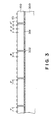
- Figure 3 is a schematic view illustrating arrangement of the heater board in the first embodiment.
- Figure 4 is a schematic view of a top plate of an ink jet recording head according to the first embodiment.
- Figure 5 is a top plan view of a cross-sectional view of a clamping unit according to the first embodiment.
- Figure 6 illustrates an urging force regulating mechanism for the clamping unit in the first embodiment.
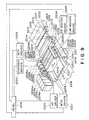
- Figure 7 illustrates a manufacturing steps for an ink jet recording head, according to the first embodiment.
- Figure 8 is a schematic view of a base plate of an ink jet head according to the first embodiment.
- Figure 9 illustrates an example of an ink jet apparatus using the ink jet head according to an embodiment of the present invention.
- Figure 10 is a schematic perspective view of an example of a conventional full-line type ink jet head.
- Figure 11 is a schematic perspective view of an ink jet recording head according to a second embodiment of the present invention.
- Figure 12 is a sectional view when the clamping force between the top plate and the heater board are released, in the second embodiment.
- Figure 13 is a schematic perspective view of a structure of a charge pin according to the second embodiment.
- Figure 14 shows a sectional view (clamped state) of the elements shown in Figure 11.
- Figure 15 is a schematic perspective view of an ink jet recording head according to a third embodiment of the present invention.
- Figure 16 is a sectional view (released state) of the elements shown in Figure 15.
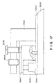
- Figure 17 is a sectional view (clamped state) of the elements shown in Figure 15.
- ink jet recording head for a first embodiment of the present invention.
- ink ejection outlets are arranged at a density of 360 dpi (70.5 ⁇ m).
- a heater board 100 is provided with 128 ejection energy generating elements 101 at the density of 360 dpi. It is provided with signal pads for driving the ejection energy generating elements 101 at proper timing by external electric signals and pads 102 for receiving electric energy for the driving.
- the heater board 100 is bonded and fixed on the surface of a base plate 300, and is of metal or ceramic material.
- Figure 3 illustrates the heater board 100 on the base plate 300.
- the heater board is provided such that the intervals between adjacent ejection energy generating elements at an end of the heater board are the same as the intervals of 70.5 ⁇ m at which the ejection energy generating elements 101 are arranged.
- the gaps between the heater boards occurring at this time are sealed by a sealant 302.
- the heater board 100 is not limited to the one described above, but one integral heater board is usable.
- the base plate 300 has a wiring board 400 bonded in the similar manner as in the heater board 100.
- the plurality of pads 102 on the heater board 100 and a plurality of pads 401 on the wiring board 400 for supplying the signal and electric energy, are made in a predetermined corresponding relation.
- the wiring board 400 is provided with a connection 402 for supplying external printing signals or driving electric energy.
- the top plate 200 will be described.
- the top plate 200 is provided with a plurality of passages 202 corresponding to the ejection energy generating elements 100 on the heater board 100, orifices 203 in fluid communication with the corresponding passages 202, respectively, to eject the ink toward the recording material, a liquid chamber 201 corrected with each of the passages 202 for supplying the ink to the liquid passages 202 an ink supply tube for constituting an ink supply passage for supplying the ink from an ink container (not shown) to the liquid chamber 201, an ink supply port 206 for supplying the ink to the liquid chamber through the ink supply tube 205.
- the top plate 200 has a length substantially covering the array of the ejection energy generating elements constituted by arranging a plurality of heater board.
- the top plate 200 is connected such that the positional relationships between the passages 202 and the ejection energy generating elements 101 on the heater board on the base plate 300, are in the predetermined corresponding relations.
- the method of connecting them is mechanical clamping using spring or the like.
- a clamping unit 700 for clamping the top plate and the heater board with each other comprises a leaf spring member 600 and a spring fixing member 500 for fixing the leaf spring member.
- FIG. 5 is a top plan view and a sectional view of the clamping unit.
- the leaf spring member 600 is of phosphor bronze, stainless steel or the like, and it is in the form of an integral leaf spring provided with slits 602.
- the portions of the leaf spring divided by the slits 602 constitute the urging portion for urging the top plate.
- the urging portion is provided with a bent portion to increase the spring rigidity for each urging portion.
- At an end of the bent portion there is provided a through opening 601.
- the end of the leaf spring adjacent the urging side has aprons 603 bent downward to effectively urge the top plate 200, at the end of the leaf spring.
- the free ends of the aprons are machined into an acute angle so that the contact or urging portion to the top plate is within the upper part of the ink passage.
- the through openings 601 are effective to permit insertion of a tool for regulating the urging force and also to be an inlet for a sealant for sealing the top plate and the wire bonding portion.
- the sealing of the top plate is effected after it is fixed using the clamping unit. In this case, if the sealant is supplied from the opposite ends of the long top plate, the sealant does not extend enough. In view of this, the sealant is injected through the openings provided for the respective urging portions.
- the front end of the through opening is preferably close to the ejection outlet to provide enough stroke of the spring. More particularly, it is preferably disposed to correspond to a front half region from the center of the depth of the top plate.
- the rear end of the through opening is preferably close to the ejection outlet under the condition that the wire bonding portion can be seen therethrough, since then the sealing can be assuredly effected without reducing the spring rigidity.
- the apron is effective to provide space between the leaf spring and the top plate, and the tool is received by the space.
- the length of the apron is determined in consideration of the strength of the tool and the rigidity of the spring.
- the integral leaf spring is used, so that the position of the urging force can be correctly aligned for the respective urging portions, and in addition, the width of the slit can be reduced.
- a spring fixing member 500 for supporting the leaf spring 600 is of resin material such as PPS, and is integrally formed with the leaf spring member 600 through insert molding or the like. At this time, in order to reinforcing the fixing portion of the leaf spring, the integral formed portion of the leaf spring is provided with a through bore 604, as shown in Figure 5, (b). The leaf spring is bent at this portion. The rear end of the leaf spring member is projected through the spring supporting member. The tool is hooked to the rear end of the leaf spring member, so that the urging force can be regulated by the leaf spring member and the spring fixing member only.
- the clamping unit 700 is fixed on the base plate 300 by crimping or screws or the like to clamp the top plate 200 and the heater board 100 by the urging force of the leaf spring member 600.
- the urging force at this time is 0.2 - 0.4 kg/mm in this embodiment, although it is dependent on the rigidity of the top plate 200. Therefore, in the case of the full line head, the urging force for the entire length, is as large as several tens kg. It is preferable that the slits are provided such that the urging forces of the respective urging portions are 4 - 5 kg. In this embodiment, the slits are provided such that the urging portions of the leaf spring member correspond to the respective heater boards.
- the clamping unit is provided with a mechanism for permitting regulating and releasing the urging force for the respective urging portions.
- Figure 6 illustrates the urging force regulating mechanism of the clamping unit.
- the clamping unit is provided with a tool 1000 for regulating the urging force, a first engaging portion 1110 in the tool 1000.
- the first engaging portion 1110 is inserted into a through opening 601 of the leaf spring member 600, and is engaged with the end of the leaf spring 600.
- a second engaging portion 1210 of the tool 1000 is engaged to the rear end of the fixing portion of the spring fixing member 500.
- Designated by 1300 is a screw for connecting a first member 1100 having the first engaging portion 1110 and a second member 1200 having the second engaging portion 1210.
- the tool 1000 is in the form of a lever with the fulcrum at the portion contacting the spring confining member 500 and with a operating point of the first engaging portion.
- the urging force of the leaf spring urging portion can be regulated.
- the screw 1300 is fixed to fix the position of the urging portion at the upper portion.
- the top plate 200 is connected with the heater board 100, all of the urging portions of the leaf spring member 600 are fixed at the upper portion as described above, and in this state, the top plate 200 is mounted.
- the rear end of the first member (1100) is elevated, by means of which the leaf spring urging portion is released so that the top plate 200 is fixed by the urging force of the leaf spring 600.
- the regulation and release of the urging force can be easily carried out between the top plate 200 and the heater board 100.
- the unit By disposing the tool between the top plate and the leaf spring, it is possible to independently adjust the respective urging forces of the urging portions so that better clamped state is provided. By effecting the regulation and release of the urging force using the removable tool, the unit can be downsized, and the durability and operativity are improved.
- Figure 7 shows the manufacturing steps for the ink jet head.
- the elongated multi-nozzle head comprises 11 heater board (HB) and one grooved top plate.
- an aluminum base plate is manufactured through die cast molding to provide a base plate having a heater board support and PCB positioning projections.
- the supporting portion is provided with an opening for sucking air for the purpose of temporarily fixing a recess for the bonding material ejection and the heater board.
- Figure 8 schematically shows a base plate die cast molded. In this Figure, it comprises a heater board support 310, a recess 311 in the heater board supporting portion, an adhesive injection groove 312 in communication with the recess, a sucking opening 313, and a positioning projection 314 for the PCB.
- the hatched portion and the surface of the supporting portion of the base plate are abraded to increase the surface property of the supporting portion, thus reducing the error in the mounting of the heater board.
- the end portions of the base plate function as the positioning portion for the apparatus, so that the manufacturing accuracy of the apparatus can be improved.
- a plurality of heater board (HB) having the electrothermal transducer element through a thin film forming technique on a silicon substrate HB
- the plurality of the heater boards are positioned with high precision using positioning tool onto the heater board supporting portion of the base plate.
- the heater board thus correctly positioned is temporarily fixed by sucking the air through the opening by a vacuum system disposed below BP. In this manner, the heater boards are sequentially positioned on the base plate (step a ).
- the adhesive material is supplied through the injection groove of the base plate.
- the adhesive material extends to the respective recesses in communication with the adhesive injection grooves by capillary force. Thereafter, it is left for a predetermined period to dry the bonding material, by which the heater board is completely secured. Thereafter, the vacuum sucking is stopped. If further strong securing is desired, the adhesive material may be injected through the sucking opening (step b).
- the base plate and the heater board are machined to remove the step at the ejection side end of the heater board.
- the top plate is abutted to the ejection side end of the heater board, as will be described hereinafter, and the machining step is effective to avoid the crosstalk (step c).
- PCB wiring board
- the electrode pads on the PCB and the electrode pads on the heater board are aligned with a predetermined positional relationship.
- the electrode pad of the PCB and the electrode pad on the heater board are electrically connected by wire bonding.
- the electroconductivity of the wire bonding is checked (step d).
- the clamping unit for contacting the top plate to the heater board on the BP (Base plate), is mounted.
- the clamping unit comprises a leaf spring member for urging the top plate to the heater board and a spring supporting member for supporting the leaf spring.
- the leaf spring has a plurality of slits to provide a plurality of divided urging portions. Each urging portion is provided with a through opening, through which a tool is inserted to regulate and release the urging force for the urging portions.
- a fixing member for the clamping unit is connected to BP (Base plate) through the PCB, and it may be fixed by screws or thermal crimp (step e).
- the urging force of the urging portions are regulated by the tool (step f).
- the alignment operation is carried out between the ink passages and the ejection energy generating elements, and the top plate is connected with the heater board (step g).
- the top plate By releasing the urging force of the urging portion, the top plate is securedly fixed. In the releasing step, the urging force is released from the central portion toward the end portions. By doing so, the warp of the top plate can be corrected, and the deformation escapes toward the other side, by which the satisfactory clamping is assured over the entire length of the heater board. After the urging force is released, the tool is removed from the recording head (step h).
- the ink supply unit is fixed on the base plate by thermal fusing or the like to the position where the ink supply tube is connected to each end of the top plate.
- the ink is supplied to the top plate.
- the ink may be supplied in both directions, or may be supplied one way and the ink is circulated.
- a filter is provided in the connection portion with the ink supply unit to trap bubbles (step i).
- a heat cover is mounted to cover the base plate, and a sealing material is injected to the top plate connecting portion and the wire bonding portion through windows provided at positions corresponding to the urging portions of the head cover (steps i and k).
- Figure 11 is a schematic perspective view of an ink jet recording head according to the second embodiment.
- Figure 12 is a sectional view thereof when the pressure between the top plate and the heater board is released.
- Figure 13 is a schematic perspective view of a charge pin.
- Figure 14 is a sectional view of the elements of Figure 11.
- a confining spring 600 is mounted on a confining spring unit 500.
- the confining spring unit 500 is fixed on the base plate 300 by crimping or screws or the like.
- the spring force for this purpose is 0.2 - 0.4 kg/mm, although it is dependent on the rigidity of the top plate 200.
- urging force producing unit constituted by the confining spring unit 500, the confining spring 600 and the charge pin 700 shown in Figures 12 and 13, is used, so that the spring force of the confining spring 600 is not imparted to the top plate 200.
- the unit for producing the clamping force is provided with a mechanism for releasing the urging force and for maintaining the clamping state.
- the confining spring unit 500 is provided with a plurality of through holes in the form of a key hole, as shown in Figure 11.
- the confining spring 600 as shown in Figure 12, a plate-like member bent at two portions and a U-shaped member connected thereto. It is accommodated below the through opening in the confining spring unit 500 so that the plate-like member is at the top. Only the plate-like member is projected to the outside of the confining spring unit 500 to be capable of urging the top plate 200.
- the charge pin 700 is inserted through the through opening in the confining spring unit 500.
- the inserting portion is provided with a locking portion 700b for maintaining the state of insertion.
- a stop 700a in the form of "L" for rotation control. The stop 700a abuts the confining spring unit 500 when the charge pin 700 is rotated, so that the amount of rotation is controlled.
- a D-cut portion is provided at the top, so that the correct insertion, alignment and rotation are facilitated.
- the charge pin 700 of the above structure is inserted into the spring unit 500 and is rotated, and is locked. By this, the contact portion between the plate-like member and the U-shaped member, is changed to raise the end position of the plate-like member functioning as the portion for confining the top plate 200, so that the clamping force to the top plate 200 is released.
- the charge pin 700 is inserted into the confining spring unit 500, as shown in Figure 12, by which the clamping force to the top plate 200 is released.
- the confining spring unit 500 and the base plate 300 are aligned with each other and are fixed together. Thereafter, the charge pin 700 is rotated in the opposite direction, and is removed. By this, the end of the confining spring 600 is brought into contact with the top plate 200, as shown in Figure 14, so that the top plate 200 and the heater board are clamped.
- the top plate 200 and the heater board 100 are clamped or released without difficulty.
- the total clamping load is as large as several tens kg, and therefore, the division is effected so that the spring force of a spring is 4 - 5 kg or lower. It is preferable that the clamping is effected from the center toward the ends, since then the top plate follows the warpage or curve or deflection of the base plate so as to provide the satisfactory clamping.
- the clamping force controlling member (charging pin) which is mountable and demountable, so that the unit is downsized, and the durability and the operativity are improved.
- Figure 15 is a schematic perspective view of an ink jet recording head according to a third embodiment of the present invention.
- Figure 16 is a sectional view when the top plate 3200 and the heater board 3100 are clamped, and Figure 17 shows them in the released state.
- a supporting plate 3510 having a L-shaped cross-section is fixed on the base plate 3300 by crimping or by screws.
- An L-shaped confining member 3610 is fixed on a wiring board 3400 with its one end as a pivot. The other end (open end) is above the top plate surface. It is urged by an adjusting screw 3520 at the top to transmit the clamping force for between the top plate 3200 and the heater board 3100. The description will be made as to when the urging force released state and the urging force applied state.
- the adjusting screw 3520 is set so as to avoid abutment to the confining member 3610.
- the charge screw 3530 is rotated to release the threaded state with the confining member 3610 is removed to free the confining member 3610.
- the end of the confining member 3610 is contacted to the top plate 3200 only by its weight, and therefore, without any clamping force.
- the confining member 3610 is urged to apply the clamping force between the top plate 3200 and the heater board 3110.
- the clamping force can be adjusted by controlling the torque of the adjusting screw 3520 and the screw rotational angle or the like.
- the clamping force between the top plate 3200 and the heater board 3100 can be controlled.
- the structure of the apparatus is simple with reduced cost and easy manufacturing.
- Figure 9 shows an example of an ink jet recording apparatus incorporating the ink jet recording head according to an embodiment of the present invention.
- the ink jet recording apparatus is provided with line-type heads 2201a - 2201d.
- the line type heads 2201a - 2201d are fixed to be extended in parallel with each other with a predetermined gap in X direction by a holder 2202.
- 3456 ejection outlets are provided directed downward and arranged in one line at the density of 16 ejection outlets per 1 mm. This permits the recording on the width of 218 mm.
- Each of the recording heads 2201a - 2201d is a type of using thermal energy, and the ejection is controlled by a head driver 2220.
- a head unit is constituted by heads 2201a - 2201d and a holder 202.
- the head unit is movable up and down by head moving means 224.
- head cap 2203a - 2203d are disposed adjacent to each other and corresponding to the associated heads 2201a - 2201d.
- ink absorbing materials such as sponge material are provided in the head caps 2203a - 2203d.
- the caps 2203a - 2203d are fixed by an unshown holder, and the capping unit includes the holder and the caps 2203a and 2203d.
- the cap unit is movable in X direction by a cap moving means 2225.
- Each of the recording heads 2201a - 2201d is supplied with either of cyan, magenta, yellow and black color ink through the associated ink supply tube 2205a - 2205d from the associated ink container 2204a - 2204d to permit color recording.
- the ink supply uses capillary force of the head ejection outlet, and the liquid surface level in each of the ink containers 2204a - 2204d is lower than a predetermined amount than the ejection outlet position.
- the apparatus is provided with an electrically chargeable seamless belt 2204 for carrying a recording sheet 227 (recording material).
- the belt is extended through a predetermined path around a driving roller 2207, idler rollers 2209, 2209a and a tension roller 2210.
- the belt is rotated by a belt driving motor 2208 connected to the driving roller 2207 and driven by a motor driver 2221.
- the belt 2206 travels in the direction X immediately below the ejection outlets of the heads 2201a - 2201d. Here, the downward deviation is suppressed by the fixing member 2226.
- Designated by a reference numeral 2217 is a cleaning unit for removing paper dust or the like from the surface of the belt 2202.
- Reference numeral 2212 is a charger for electrically charging the belt 2206.
- the charger 2212 is actuated or deactuated by a charger driver 2222 so that the recording sheet is attracted on the belt 2206 by electrostatic attraction force.
- pinch rollers 2211 and 2211a to cooperate with the idler rollers 2209 and 2209a to urge the recording sheet 2227 to the belt 2206.
- Reference numeral 2232 designates a sheet feeding cassette.
- the recording sheets 2227 in the cassette is fed out one-by-one by a pick up roller 2216 driven by a motor driver 2223. It is further fed to a mountain like guide 2213 in X direction by feeding roller 2214 and a pinch roller 2215 driven by the driver 2223.
- the guide 2213 defines a mountain like space to permit deformation of the recording sheet.
- Reference numeral 2218 designates a sheet discharge tray to which the recording sheet is discharged after the printing or recording operation.
- the above-described head driver 2220, head moving means 2224, cap moving means 2225, motor drivers 2221 and 2223 and the charger driver 2222 are all controlled by a control circuit 2219.
- the ink is used as the liquid. In place thereof, however, the use can be made with an ink which is solid under the room temperature or lower, but softened or liquefied at the room temperature.
- the ink jet recording system the ink itself is kept at the temperature of 30 - 70 °C to stabilize the ink viscosity within a predetermined range. Therefore, the ink is usable if it is in the form of liquid upon the recording signal application.
- the ink may be solid if it is liquefied upon heating.
- the present invention is applicable to a textile printer or to a textile printing system incorporating the textile printer and the preprocessing apparatus and a post-processing apparatus to which the long size ink jet head is highly desirable. Therefore, fine and high quality print is permitted in the textile printing apparatus and system.
- the present invention is also applicable to a facsimile machine, a copying machine, or printer, and in that case, the prints without image disturbance can be formed.
- the present invention is particularly suitably usable in an ink jet recording head and recording apparatus wherein thermal energy by an electrothermal transducer, laser beam or the like is used to cause a change of state of the ink to eject or discharge the ink. This is because the high density of the picture elements and the high resolution of the recording are possible.
- the typical structure and the operational principle are preferably the ones disclosed in U.S. Patent Nos. 4,723,129 and 4,740,796.
- the principle and structure are applicable to a so-called on-demand type recording system and a continuous type recording system.
- it is suitable for the on-demand type because the principle is such that at least one driving signal is applied to an electrothermal transducer disposed on a liquid (ink) retaining sheet or liquid passage, the driving signal being enough to provide such a quick temperature rise beyond a departure from nucleation boiling point, by which the thermal energy is provided by the electrothermal transducer to produce film boiling on the heating portion of the recording head, whereby a bubble can be formed in the liquid (ink) corresponding to each of the driving signals.
- the liquid (ink) is ejected through an ejection outlet to produce at least one droplet.
- the driving signal is preferably in the form of a pulse, because the development and contraction of the bubble can be effected instantaneously, and therefore, the liquid (ink) is ejected with quick response.
- the driving signal in the form of the pulse is preferably such as disclosed in U.S. Patents Nos. 4,463,359 and 4,345,262.
- the temperature increasing rate of the heating surface is preferably such as disclosed in U.S. Patent No. 4,313,124.
- the structure of the recording head may be as shown in U.S. Patent Nos. 4,558,333 and 4,459,600 wherein the heating portion is disposed at a bent portion, as well as the structure of the combination of the ejection outlet, liquid passage and the electrothermal transducer as disclosed in the above-mentioned patents.
- the present invention is applicable to the structure disclosed in Japanese Laid-Open Patent Application No. 123670/1984 wherein a common slit is used as the ejection outlet for plural electrothermal transducers, and to the structure disclosed in Japanese Laid-Open Patent Application No. 138461/1984 wherein an opening for absorbing pressure wave of the thermal energy is formed corresponding to the ejecting portion.
- the provisions of the recovery means and/or the auxiliary means for the preliminary operation are preferable, because they can further stabilize the effects of the present invention.
- preliminary heating means which may be the electrothermal transducer, an additional heating element or a combination thereof.
- means for effecting preliminary ejection (not for the recording operation) can stabilize the recording operation.
- the ink jet recording apparatus may be used as an output terminal of an information processing apparatus such as computer or the like, as a copying apparatus combined with an image reader or the like, or as a facsimile machine having information sending and receiving functions.
Description
- The present invention relates to an ink jet recording head manufacturing method and an ink jet recording head.
- In a recording apparatus such as a printer, copying machine, facsimile machine or the like, an image consisting of dots is recorded on a recording material such as paper, plastic resin thin sheet, cloth or the like.
- The recording apparatus can be classified into an ink jet type, a wire dot type, a thermal type, an electrophotographic type and the like. Among them, the ink jet type (ink jet recording apparatus) ejects the recording liquid through the ejection outlets of an ink jet recording head to the recording material. Among various types of ink jet method, the type using thermal energy is advantageous in that the responsivity to the recording signal is high and in that the ejection outlets can be manufactured at high density.
- Recently, the amount of data to be recorded is increased, more particularly, graphic patterns or the like are printed with the result of the greater amount of data to be printed, so that even higher high speed recording is desired.
- An ink jet recording apparatus of the above-described type and of a so-called full line type having a long ink jet recording head having ejection outlets over the recording material width, is expected as increasing the recording speed.
- Referring first to Figure 10, there is schematically shown an example of a conventional ink jet head.
- As shown in Figure 10, it is elongated to cover a length of a side of A4 size recording sheet (full-line type).
- In this Figure, designated by a
reference numeral 100 is a heater board of Si or the like. On top of this, there are provided electrothermal transducers functioning as ejection energy generating elements and electrode wiring (not shown) for supplying the electric power thereto. Designated by 200 is a top plate of glass or metal or the like. It has a recess manufactured by machining or etching or the like to constitute anink inlet 209 for receiving recording liquid such as ink, and a common liquid chamber in fluid communication with respective ink passages and with theink receiving port 209. - Each ink passage is provided corresponding to the ejection energy generating element on the
heater board 100. The top plate is bonded on theheater board 100, and theheater board 100 is bonded and fixed on thebase plate 300. Aconfining member 500 functions to connecting and fixing thetop plate 200 and theheater board 100. It is threaded on thebase plate 300 through thewiring board 400. On top of theconfining member 500, an end of aconfining spring 600 is fixed by a screw. The other end thereof is contacted to the top surface of thetop plate 200 to elastically press thetop plate 200. By doing so, thetop plate 200 can be mechanically urged to theheater board 1. - With this structure, if the top plate involves warping or deformation, it is not possible to press the top plate following the warping or deformation, with the result of non-uniform urging force by the confining spring in the direction of the length. If this occurs, a gap may be formed between adjacent passages. In the ink jet head of this type, there is a possibility that the pressure wave upon ejecting the recording liquid may be transmitted to the adjacent ink passages with the result of cross-talk. If this occurs, non-uniformity occurs on the recorded image, and in addition, ejection failure may occur as a result of the reduction of the ejection speed. Japanese Laid-Open Patent Application No. 126943/1994 corresponding to EP 593040A proposes comb-like confining spring to make the spring urging force uniform.
- However, when the top plate is to be pressed, it is necessary to correctly align the heater board and the top plate so that the ink passages correspond to the associated ejection energy generating element, respectively. However, with this structure, when the confining spring is mounted before the top plate is mounted, the confining spring is present at a part of the place to be taken by the top plate, and therefore, it is not possible to align and connect the top plate after the confining spring is fixed. For this reason, the confining spring is mounted after the top plate is aligned. In this case, however, if the fixing of the confining spring is executed partially, the fixed portion (screw portion) involves concentrated force with the result of the liability of the deformation of the spring, because the urging force by the confining spring is several tens kg in total. Therefore, the uniform urging is difficult. Therefore, in order to apply the uniform urging force by the confining spring, the fixing of the confining spring has to be uniform. In this case, a very bulky apparatus is required with the result of increase manufacturing cost.
- According to document US 5,257,043 A there is disclosed an ink jet recording head and a method for producing the same, said ink jet recording head comprising a plurality of ink ejection outlets, a first member having a plurality of grooves in fluid communication with said ejection outlets, respectively a second member having a plurality of energy generating elements for producing energy for ejecting ink in said grooves through said ejection outlets and a clamping unit for clamping the first member with the second member in order to constitute ink passages with grooves.
- It is the object of the invention to provide a manufacturing method for manufacturing an ink jet recording head and an ink jet recording head by means of which an easy and simple manufacturing thereof can be achieved.
- The above object is solved by the combination of the features set forth in each of the independent claims. Preferable embodiments of the invention are defined in the subclaims.
- The features and advantages of the present invention will become more apparent upon a consideration of the following description of the preferred embodiments of the present invention taken in conjunction with the accompanying drawings.
- Figure 1 is a schematic perspective view of an ink jet recording head according to a first embodiment of the present invention.
- Figure 2 is a schematic perspective view of the ink jet recording head according to the first embodiment of the present invention.
- Figure 3 is a schematic view illustrating arrangement of the heater board in the first embodiment.
- Figure 4 is a schematic view of a top plate of an ink jet recording head according to the first embodiment.
- Figure 5 is a top plan view of a cross-sectional view of a clamping unit according to the first embodiment.
- Figure 6 illustrates an urging force regulating mechanism for the clamping unit in the first embodiment.
- Figure 7 illustrates a manufacturing steps for an ink jet recording head, according to the first embodiment.
- Figure 8 is a schematic view of a base plate of an ink jet head according to the first embodiment.
- Figure 9 illustrates an example of an ink jet apparatus using the ink jet head according to an embodiment of the present invention.
- Figure 10 is a schematic perspective view of an example of a conventional full-line type ink jet head.
- Figure 11 is a schematic perspective view of an ink jet recording head according to a second embodiment of the present invention.
- Figure 12 is a sectional view when the clamping force between the top plate and the heater board are released, in the second embodiment.
- Figure 13 is a schematic perspective view of a structure of a charge pin according to the second embodiment.
- Figure 14 shows a sectional view (clamped state) of the elements shown in Figure 11.
- Figure 15 is a schematic perspective view of an ink jet recording head according to a third embodiment of the present invention.
- Figure 16 is a sectional view (released state) of the elements shown in Figure 15.
- Figure 17 is a sectional view (clamped state) of the elements shown in Figure 15.
- Referring to the accompanying drawings, the embodiments of the invention will be described.
- Referring to Figures 1 and 2, there are shown an ink jet recording head for a first embodiment of the present invention. In this embodiment, ink ejection outlets are arranged at a density of 360 dpi (70.5 µm).
- In Figure 2, a
heater board 100 is provided with 128 ejectionenergy generating elements 101 at the density of 360 dpi. It is provided with signal pads for driving the ejectionenergy generating elements 101 at proper timing by external electric signals andpads 102 for receiving electric energy for the driving. - The
heater board 100 is bonded and fixed on the surface of abase plate 300, and is of metal or ceramic material. - Figure 3 illustrates the
heater board 100 on thebase plate 300. A plurality ofheater board 100 per mounted on thebase plate 300, and are bonded and fixed by a predetermined thickness ofadhesive material 301 at predetermined positions on thebase plate 300. The heater board is provided such that the intervals between adjacent ejection energy generating elements at an end of the heater board are the same as the intervals of 70.5 µm at which the ejectionenergy generating elements 101 are arranged. The gaps between the heater boards occurring at this time, are sealed by asealant 302. Theheater board 100 is not limited to the one described above, but one integral heater board is usable. - Referring back to Figure 2, the
base plate 300 has awiring board 400 bonded in the similar manner as in theheater board 100. The plurality ofpads 102 on theheater board 100 and a plurality ofpads 401 on thewiring board 400 for supplying the signal and electric energy, are made in a predetermined corresponding relation. Thewiring board 400 is provided with aconnection 402 for supplying external printing signals or driving electric energy. - Referring to Figure 4, the
top plate 200 will be described. In Figure 4, thetop plate 200 is provided with a plurality ofpassages 202 corresponding to the ejectionenergy generating elements 100 on theheater board 100,orifices 203 in fluid communication with the correspondingpassages 202, respectively, to eject the ink toward the recording material, aliquid chamber 201 corrected with each of thepassages 202 for supplying the ink to theliquid passages 202 an ink supply tube for constituting an ink supply passage for supplying the ink from an ink container (not shown) to theliquid chamber 201, anink supply port 206 for supplying the ink to the liquid chamber through theink supply tube 205. Thetop plate 200 has a length substantially covering the array of the ejection energy generating elements constituted by arranging a plurality of heater board. - Referring back to Figure 1, the
top plate 200 is connected such that the positional relationships between thepassages 202 and the ejectionenergy generating elements 101 on the heater board on thebase plate 300, are in the predetermined corresponding relations. - The method of connecting them is mechanical clamping using spring or the like.
- In Figure 1, a
clamping unit 700 for clamping the top plate and the heater board with each other comprises aleaf spring member 600 and aspring fixing member 500 for fixing the leaf spring member. - Figure 5 is a top plan view and a sectional view of the clamping unit. The
leaf spring member 600 is of phosphor bronze, stainless steel or the like, and it is in the form of an integral leaf spring provided withslits 602. The portions of the leaf spring divided by theslits 602 constitute the urging portion for urging the top plate. The urging portion is provided with a bent portion to increase the spring rigidity for each urging portion. At an end of the bent portion there is provided a throughopening 601. The end of the leaf spring adjacent the urging side, hasaprons 603 bent downward to effectively urge thetop plate 200, at the end of the leaf spring. The free ends of the aprons are machined into an acute angle so that the contact or urging portion to the top plate is within the upper part of the ink passage. By the concentrated urging to the ink passage portion, the ink passage walls between the neighborhood of the ejection outlet and the heat generating portion, which is most influential to the cross-talk, can be assuredly urged to the heater board. - The through
openings 601 are effective to permit insertion of a tool for regulating the urging force and also to be an inlet for a sealant for sealing the top plate and the wire bonding portion. The sealing of the top plate is effected after it is fixed using the clamping unit. In this case, if the sealant is supplied from the opposite ends of the long top plate, the sealant does not extend enough. In view of this, the sealant is injected through the openings provided for the respective urging portions. The front end of the through opening is preferably close to the ejection outlet to provide enough stroke of the spring. More particularly, it is preferably disposed to correspond to a front half region from the center of the depth of the top plate. In addition, the rear end of the through opening is preferably close to the ejection outlet under the condition that the wire bonding portion can be seen therethrough, since then the sealing can be assuredly effected without reducing the spring rigidity. - The apron is effective to provide space between the leaf spring and the top plate, and the tool is received by the space. The length of the apron is determined in consideration of the strength of the tool and the rigidity of the spring.
- According to this embodiment, the integral leaf spring is used, so that the position of the urging force can be correctly aligned for the respective urging portions, and in addition, the width of the slit can be reduced.
- A
spring fixing member 500 for supporting theleaf spring 600 is of resin material such as PPS, and is integrally formed with theleaf spring member 600 through insert molding or the like. At this time, in order to reinforcing the fixing portion of the leaf spring, the integral formed portion of the leaf spring is provided with a throughbore 604, as shown in Figure 5, (b). The leaf spring is bent at this portion. The rear end of the leaf spring member is projected through the spring supporting member. The tool is hooked to the rear end of the leaf spring member, so that the urging force can be regulated by the leaf spring member and the spring fixing member only. Theclamping unit 700 is fixed on thebase plate 300 by crimping or screws or the like to clamp thetop plate 200 and theheater board 100 by the urging force of theleaf spring member 600. The urging force at this time is 0.2 - 0.4 kg/mm in this embodiment, although it is dependent on the rigidity of thetop plate 200. Therefore, in the case of the full line head, the urging force for the entire length, is as large as several tens kg. It is preferable that the slits are provided such that the urging forces of the respective urging portions are 4 - 5 kg. In this embodiment, the slits are provided such that the urging portions of the leaf spring member correspond to the respective heater boards. - The clamping unit is provided with a mechanism for permitting regulating and releasing the urging force for the respective urging portions.
- Figure 6 illustrates the urging force regulating mechanism of the clamping unit.
- In Figure 6, the clamping unit is provided with a
tool 1000 for regulating the urging force, a first engagingportion 1110 in thetool 1000. The firstengaging portion 1110 is inserted into a throughopening 601 of theleaf spring member 600, and is engaged with the end of theleaf spring 600. A second engagingportion 1210 of thetool 1000 is engaged to the rear end of the fixing portion of thespring fixing member 500. Designated by 1300 is a screw for connecting afirst member 1100 having the first engagingportion 1110 and asecond member 1200 having the second engagingportion 1210. - The
tool 1000 is in the form of a lever with the fulcrum at the portion contacting thespring confining member 500 and with a operating point of the first engaging portion. By lowering the rear end of the first member, the urging force of the leaf spring urging portion can be regulated. With this state maintained, thescrew 1300 is fixed to fix the position of the urging portion at the upper portion. When thetop plate 200 is connected with theheater board 100, all of the urging portions of theleaf spring member 600 are fixed at the upper portion as described above, and in this state, thetop plate 200 is mounted. After the completion of the alignment of thetop plate 200, the rear end of the first member (1100) is elevated, by means of which the leaf spring urging portion is released so that thetop plate 200 is fixed by the urging force of theleaf spring 600. - As described above, by the use of the urging force regulating tool, the regulation and release of the urging force can be easily carried out between the
top plate 200 and theheater board 100. - By disposing the tool between the top plate and the leaf spring, it is possible to independently adjust the respective urging forces of the urging portions so that better clamped state is provided. By effecting the regulation and release of the urging force using the removable tool, the unit can be downsized, and the durability and operativity are improved.
- A manufacturing method of the ink jet recording head will be described in conjunction with Figure 7.
- Figure 7 shows the manufacturing steps for the ink jet head. In this embodiment, the elongated multi-nozzle head comprises 11 heater board (HB) and one grooved top plate.
- First, an aluminum base plate is manufactured through die cast molding to provide a base plate having a heater board support and PCB positioning projections. The supporting portion is provided with an opening for sucking air for the purpose of temporarily fixing a recess for the bonding material ejection and the heater board. Figure 8 schematically shows a base plate die cast molded. In this Figure, it comprises a
heater board support 310, arecess 311 in the heater board supporting portion, anadhesive injection groove 312 in communication with the recess, a suckingopening 313, and apositioning projection 314 for the PCB. The hatched portion and the surface of the supporting portion of the base plate are abraded to increase the surface property of the supporting portion, thus reducing the error in the mounting of the heater board. The end portions of the base plate function as the positioning portion for the apparatus, so that the manufacturing accuracy of the apparatus can be improved. - On the other hand, a plurality of heater board (HB) having the electrothermal transducer element through a thin film forming technique on a silicon substrate.
- Subsequently, the plurality of the heater boards are positioned with high precision using positioning tool onto the heater board supporting portion of the base plate. The heater board thus correctly positioned is temporarily fixed by sucking the air through the opening by a vacuum system disposed below BP. In this manner, the heater boards are sequentially positioned on the base plate (step a).
- The adhesive material is supplied through the injection groove of the base plate. The adhesive material extends to the respective recesses in communication with the adhesive injection grooves by capillary force. Thereafter, it is left for a predetermined period to dry the bonding material, by which the heater board is completely secured. Thereafter, the vacuum sucking is stopped. If further strong securing is desired, the adhesive material may be injected through the sucking opening (step b).
- After the completion of the arrangement and fixing of the heater board, the base plate and the heater board are machined to remove the step at the ejection side end of the heater board. By doing so, the top plate is abutted to the ejection side end of the heater board, as will be described hereinafter, and the machining step is effective to avoid the crosstalk (step c).
- Subsequently, PCB (wiring board) is bonded to the base plate with the correct positioning using the positioning projections described hereinbefore. By doing so, the electrode pads on the PCB and the electrode pads on the heater board are aligned with a predetermined positional relationship. Then, the electrode pad of the PCB and the electrode pad on the heater board are electrically connected by wire bonding. In this step, the electroconductivity of the wire bonding is checked (step d).
- Subsequently, a clamping unit for contacting the top plate to the heater board on the BP (Base plate), is mounted. The clamping unit comprises a leaf spring member for urging the top plate to the heater board and a spring supporting member for supporting the leaf spring. The leaf spring has a plurality of slits to provide a plurality of divided urging portions. Each urging portion is provided with a through opening, through which a tool is inserted to regulate and release the urging force for the urging portions.
- When the clamping unit is fixed to the PCB, a fixing member for the clamping unit is connected to BP (Base plate) through the PCB, and it may be fixed by screws or thermal crimp (step e).
- In order to connect the top plate to the heater board, the urging force of the urging portions are regulated by the tool (step f).
- After the sufficient space is assured on the heater board, the alignment operation is carried out between the ink passages and the ejection energy generating elements, and the top plate is connected with the heater board (step g).
- By releasing the urging force of the urging portion, the top plate is securedly fixed. In the releasing step, the urging force is released from the central portion toward the end portions. By doing so, the warp of the top plate can be corrected, and the deformation escapes toward the other side, by which the satisfactory clamping is assured over the entire length of the heater board. After the urging force is released, the tool is removed from the recording head (step h).
- The ink supply unit is fixed on the base plate by thermal fusing or the like to the position where the ink supply tube is connected to each end of the top plate. By the ink supply unit, the ink is supplied to the top plate. The ink may be supplied in both directions, or may be supplied one way and the ink is circulated. In the connection portion with the ink supply unit, a filter is provided to trap bubbles (step i).
- Finally, a heat cover is mounted to cover the base plate, and a sealing material is injected to the top plate connecting portion and the wire bonding portion through windows provided at positions corresponding to the urging portions of the head cover (steps i and k).
- Referring to Figures 11 - 14, a second embodiment of the present invention will be described. Figure 11 is a schematic perspective view of an ink jet recording head according to the second embodiment. Figure 12 is a sectional view thereof when the pressure between the top plate and the heater board is released. Figure 13 is a schematic perspective view of a charge pin. Figure 14 is a sectional view of the elements of Figure 11. As shown in Figure 11, a confining
spring 600 is mounted on a confiningspring unit 500. The confiningspring unit 500 is fixed on thebase plate 300 by crimping or screws or the like. By the spring force of the confiningspring 600, thetop plate 200 and theheater board 100 are clamped. The spring force for this purpose is 0.2 - 0.4 kg/mm, although it is dependent on the rigidity of thetop plate 200. - When the
top plate 200 is fixed on thebase plate 300, urging force producing unit constituted by the confiningspring unit 500, the confiningspring 600 and thecharge pin 700 shown in Figures 12 and 13, is used, so that the spring force of the confiningspring 600 is not imparted to thetop plate 200. The unit for producing the clamping force is provided with a mechanism for releasing the urging force and for maintaining the clamping state. - The confining
spring unit 500 is provided with a plurality of through holes in the form of a key hole, as shown in Figure 11. The confiningspring 600, as shown in Figure 12, a plate-like member bent at two portions and a U-shaped member connected thereto. It is accommodated below the through opening in the confiningspring unit 500 so that the plate-like member is at the top. Only the plate-like member is projected to the outside of the confiningspring unit 500 to be capable of urging thetop plate 200. - The
charge pin 700 is inserted through the through opening in the confiningspring unit 500. As shown in Figure 13, the inserting portion is provided with a lockingportion 700b for maintaining the state of insertion. In the non-insertion portion, there is provided a stop 700a in the form of "L" for rotation control. The stop 700a abuts the confiningspring unit 500 when thecharge pin 700 is rotated, so that the amount of rotation is controlled. In order to determine the direction of thecharge pin 700, a D-cut portion is provided at the top, so that the correct insertion, alignment and rotation are facilitated. - The
charge pin 700 of the above structure is inserted into thespring unit 500 and is rotated, and is locked. By this, the contact portion between the plate-like member and the U-shaped member, is changed to raise the end position of the plate-like member functioning as the portion for confining thetop plate 200, so that the clamping force to thetop plate 200 is released. - When the
top plate 200 and theheater board 100 are clamped, thecharge pin 700 is inserted into the confiningspring unit 500, as shown in Figure 12, by which the clamping force to thetop plate 200 is released. The confiningspring unit 500 and thebase plate 300 are aligned with each other and are fixed together. Thereafter, thecharge pin 700 is rotated in the opposite direction, and is removed. By this, the end of the confiningspring 600 is brought into contact with thetop plate 200, as shown in Figure 14, so that thetop plate 200 and the heater board are clamped. - As described above, by the operation of the charge pin in the up and down direction and the rotational direction, the
top plate 200 and theheater board 100 are clamped or released without difficulty. - In the line type head shown in this embodiment, the total clamping load is as large as several tens kg, and therefore, the division is effected so that the spring force of a spring is 4 - 5 kg or lower. It is preferable that the clamping is effected from the center toward the ends, since then the top plate follows the warpage or curve or deflection of the base plate so as to provide the satisfactory clamping. By providing a member between the comfining spring and the confining spring unit so as to permit independent adjustment of the respective confining forces, and therefore, it is preferable. As in this embodiment, by providing the clamping force controlling member (charging pin) which is mountable and demountable, so that the unit is downsized, and the durability and the operativity are improved.
- Referring to Figures 15 - 17, a third embodiment will be described. Figure 15 is a schematic perspective view of an ink jet recording head according to a third embodiment of the present invention. Figure 16 is a sectional view when the
top plate 3200 and theheater board 3100 are clamped, and Figure 17 shows them in the released state. - As shown in Figure 15, a supporting
plate 3510 having a L-shaped cross-section, is fixed on thebase plate 3300 by crimping or by screws. An L-shaped confiningmember 3610 is fixed on awiring board 3400 with its one end as a pivot. The other end (open end) is above the top plate surface. It is urged by an adjustingscrew 3520 at the top to transmit the clamping force for between thetop plate 3200 and theheater board 3100. The description will be made as to when the urging force released state and the urging force applied state. - As shown in Figure 16, in the released state (mounting process), it is fixed to the supporting
member 3510 by the chargingscrew 3530. - The adjusting
screw 3520 is set so as to avoid abutment to the confiningmember 3610. - With this state, the
charge screw 3530 is rotated to release the threaded state with the confiningmember 3610 is removed to free the confiningmember 3610. The end of the confiningmember 3610 is contacted to thetop plate 3200 only by its weight, and therefore, without any clamping force. - By rotating the adjusting screw, as shown in FIgure 17, the confining
member 3610 is urged to apply the clamping force between thetop plate 3200 and the heater board 3110. The clamping force can be adjusted by controlling the torque of the adjustingscrew 3520 and the screw rotational angle or the like. - Thus, only by the control of the adjusting screw, the clamping force between the
top plate 3200 and theheater board 3100 can be controlled. Thus, the structure of the apparatus is simple with reduced cost and easy manufacturing. - Figure 9 shows an example of an ink jet recording apparatus incorporating the ink jet recording head according to an embodiment of the present invention.
- As shown in Figure 9, the ink jet recording apparatus is provided with line-type heads 2201a - 2201d. The line type heads 2201a - 2201d, are fixed to be extended in parallel with each other with a predetermined gap in X direction by a
holder 2202. In the bottom surface of each of the recording heads 2201a - 2201d, 3456 ejection outlets are provided directed downward and arranged in one line at the density of 16 ejection outlets per 1 mm. This permits the recording on the width of 218 mm. Each of the recording heads 2201a - 2201d is a type of using thermal energy, and the ejection is controlled by ahead driver 2220. - A head unit is constituted by heads 2201a - 2201d and a
holder 202. The head unit is movable up and down by head moving means 224. - Below the heads 2201a - 2201d, head cap 2203a - 2203d are disposed adjacent to each other and corresponding to the associated heads 2201a - 2201d. In the head caps 2203a - 2203d, ink absorbing materials such as sponge material are provided.
- The caps 2203a - 2203d are fixed by an unshown holder, and the capping unit includes the holder and the
caps 2203a and 2203d. The cap unit is movable in X direction by acap moving means 2225. Each of the recording heads 2201a - 2201d, is supplied with either of cyan, magenta, yellow and black color ink through the associatedink supply tube 2205a - 2205d from the associatedink container 2204a - 2204d to permit color recording. - The ink supply uses capillary force of the head ejection outlet, and the liquid surface level in each of the
ink containers 2204a - 2204d is lower than a predetermined amount than the ejection outlet position. - The apparatus is provided with an electrically chargeable seamless belt 2204 for carrying a recording sheet 227 (recording material).
- The belt is extended through a predetermined path around a driving roller 2207,
idler rollers belt driving motor 2208 connected to the driving roller 2207 and driven by amotor driver 2221. - The
belt 2206 travels in the direction X immediately below the ejection outlets of the heads 2201a - 2201d. Here, the downward deviation is suppressed by the fixing member 2226. - Designated by a reference numeral 2217 is a cleaning unit for removing paper dust or the like from the surface of the
belt 2202. -
Reference numeral 2212 is a charger for electrically charging thebelt 2206. Thecharger 2212 is actuated or deactuated by acharger driver 2222 so that the recording sheet is attracted on thebelt 2206 by electrostatic attraction force. - Before and after the
charger 2212, there are providedpinch rollers idler rollers recording sheet 2227 to thebelt 2206. -
Reference numeral 2232 designates a sheet feeding cassette. Therecording sheets 2227 in the cassette is fed out one-by-one by a pick uproller 2216 driven by amotor driver 2223. It is further fed to a mountain likeguide 2213 in X direction by feedingroller 2214 and apinch roller 2215 driven by thedriver 2223. Theguide 2213 defines a mountain like space to permit deformation of the recording sheet. -
Reference numeral 2218 designates a sheet discharge tray to which the recording sheet is discharged after the printing or recording operation. - The above-described
head driver 2220,head moving means 2224, cap movingmeans 2225,motor drivers charger driver 2222 are all controlled by acontrol circuit 2219. In the embodiments described-above, the ink is used as the liquid. In place thereof, however, the use can be made with an ink which is solid under the room temperature or lower, but softened or liquefied at the room temperature. In the ink jet recording system, the ink itself is kept at the temperature of 30 - 70 °C to stabilize the ink viscosity within a predetermined range. Therefore, the ink is usable if it is in the form of liquid upon the recording signal application. The ink may be solid if it is liquefied upon heating. - The present invention is applicable to a textile printer or to a textile printing system incorporating the textile printer and the preprocessing apparatus and a post-processing apparatus to which the long size ink jet head is highly desirable. Therefore, fine and high quality print is permitted in the textile printing apparatus and system.
- In addition, the present invention is also applicable to a facsimile machine, a copying machine, or printer, and in that case, the prints without image disturbance can be formed.
- The present invention is particularly suitably usable in an ink jet recording head and recording apparatus wherein thermal energy by an electrothermal transducer, laser beam or the like is used to cause a change of state of the ink to eject or discharge the ink. This is because the high density of the picture elements and the high resolution of the recording are possible.
- The typical structure and the operational principle are preferably the ones disclosed in U.S. Patent Nos. 4,723,129 and 4,740,796. The principle and structure are applicable to a so-called on-demand type recording system and a continuous type recording system. Particularly, however, it is suitable for the on-demand type because the principle is such that at least one driving signal is applied to an electrothermal transducer disposed on a liquid (ink) retaining sheet or liquid passage, the driving signal being enough to provide such a quick temperature rise beyond a departure from nucleation boiling point, by which the thermal energy is provided by the electrothermal transducer to produce film boiling on the heating portion of the recording head, whereby a bubble can be formed in the liquid (ink) corresponding to each of the driving signals. By the production, development and contraction of the the bubble, the liquid (ink) is ejected through an ejection outlet to produce at least one droplet. The driving signal is preferably in the form of a pulse, because the development and contraction of the bubble can be effected instantaneously, and therefore, the liquid (ink) is ejected with quick response. The driving signal in the form of the pulse is preferably such as disclosed in U.S. Patents Nos. 4,463,359 and 4,345,262. In addition, the temperature increasing rate of the heating surface is preferably such as disclosed in U.S. Patent No. 4,313,124.
- The structure of the recording head may be as shown in U.S. Patent Nos. 4,558,333 and 4,459,600 wherein the heating portion is disposed at a bent portion, as well as the structure of the combination of the ejection outlet, liquid passage and the electrothermal transducer as disclosed in the above-mentioned patents. In addition, the present invention is applicable to the structure disclosed in Japanese Laid-Open Patent Application No. 123670/1984 wherein a common slit is used as the ejection outlet for plural electrothermal transducers, and to the structure disclosed in Japanese Laid-Open Patent Application No. 138461/1984 wherein an opening for absorbing pressure wave of the thermal energy is formed corresponding to the ejecting portion.
- The provisions of the recovery means and/or the auxiliary means for the preliminary operation are preferable, because they can further stabilize the effects of the present invention. As for such means, there are capping means for the recording head, cleaning means therefor, pressing or sucking means, preliminary heating means which may be the electrothermal transducer, an additional heating element or a combination thereof. Also, means for effecting preliminary ejection (not for the recording operation) can stabilize the recording operation.
- The ink jet recording apparatus may be used as an output terminal of an information processing apparatus such as computer or the like, as a copying apparatus combined with an image reader or the like, or as a facsimile machine having information sending and receiving functions.
Claims (10)
- A manufacturing method for manufacturing an ink jet recording head including a plurality of ink ejection outlets; a first member (200; 3200) having a plurality of grooves in fluid communication with said ejection outlets, respectively; a second member (100; 3100) having a plurality of energy generating elements (101) for producing energy for ejecting ink in said grooves through said ejection outlets; and a clamping unit (600, 700) and a supporting member (300) for clamping therebetween said first member with said second member to constitute ink passages with said grooves, said method comprising the steps of:placing said second member on said supporting member;connecting said clamping unit to said supporting member with said second member interposed therebetween, wherein said clamping unit has a leaf spring member divided into a plurality of urging sections by slits (602), each section having a through opening (601), and a spring supporting member (500), wherein independently operable force regulating mechanisms are provided for said urging sections;regulating forces of said urging sections by engaging tool means with said openings;placing said first member to said second member under said clamping unit, after said regulating step;releasing the force to permit clamping between said first member (200; 3200); and said second member (100; 3100); andremoving said engaging tool means from said head after said releasing step.
- A method according to claim 1, wherein said recording head is a line head which substantially covers an entire width of a recording material.
- A method according to claim 1, wherein said urging force is regulated by said tool means.
- A method according to claim 1, further comprising a plurality of said second members.
- A method according to claim 3, wherein rear ends of said urging sections are projected beyond said second member for supporting said urging sections, and the projected portions are engageable with the tool means through openings formed in the second member.
- A method according to claim 4, wherein said urging sections correspond to said second members respectively.
- A method according to claim 4, wherein said clamping portions bridge over said second members.
- A manufacturing method according to claim 1, said method further including the step of supplying sealing material through said openings to apply the sealing material through said openings to a connecting portion between said first member (200; 3200) and said second member (100; 3100).
- An ink jet recording head including a plurality of ink ejection outlets; a first member (200; 3200) having a plurality of grooves in fluid communication with said ejection outlets, respectively; a second member (100; 3100) having a plurality of energy generating elements for producing energy for ejecting ink in said grooves through said ejection outlets; and a clamping unit (700) for clamping said first member with said second member to constitute ink passages with said grooves, wherein said clamping unit has a leaf spring member divided into a plurality of urging sections by slits (602) each section having a through opening (601), and a spring supporting member (500), and wherein independently operable force regulating mechanisms are provided for said urging sections.
- An ink jet recording head according to claim 9, wherein said ink jet recording head is obtainable by the method according to one of claims 1 to 8.
Applications Claiming Priority (6)
| Application Number | Priority Date | Filing Date | Title |
|---|---|---|---|
| JP34929/94 | 1994-03-04 | ||
| JP3492994 | 1994-03-04 | ||
| JP3492994A JP3255787B2 (en) | 1994-03-04 | 1994-03-04 | Inkjet recording head |
| JP26706494 | 1994-10-31 | ||
| JP267064/94 | 1994-10-31 | ||
| JP6267064A JPH08127129A (en) | 1994-10-31 | 1994-10-31 | Ink jet recording head and manufacture thereof |
Publications (3)
| Publication Number | Publication Date |
|---|---|
| EP0670220A2 EP0670220A2 (en) | 1995-09-06 |
| EP0670220A3 EP0670220A3 (en) | 1996-02-21 |
| EP0670220B1 true EP0670220B1 (en) | 2003-02-19 |
Family
ID=26373801
Family Applications (1)
| Application Number | Title | Priority Date | Filing Date |
|---|---|---|---|
| EP95103047A Expired - Lifetime EP0670220B1 (en) | 1994-03-04 | 1995-03-03 | An ink jet recording apparatus |
Country Status (7)
| Country | Link |
|---|---|
| US (1) | US6168254B1 (en) |
| EP (1) | EP0670220B1 (en) |
| KR (1) | KR0156795B1 (en) |
| CN (1) | CN1051282C (en) |
| CA (1) | CA2143895C (en) |
| DE (1) | DE69529633T2 (en) |
| SG (1) | SG59905A1 (en) |
Families Citing this family (14)
| Publication number | Priority date | Publication date | Assignee | Title |
|---|---|---|---|---|
| SG52140A1 (en) | 1994-03-04 | 1998-09-28 | Canon Kk | Ink jet recording head and method of manufacture therefor and laser processing apparatus and ink jet recording apparatus |
| JP3115549B2 (en) * | 1996-09-30 | 2000-12-11 | キヤノン株式会社 | INK JET RECORDING APPARATUS, RECORDING METHOD, ASSISTANT MEMBER, INK JET HEAD, AND WARP CONTROL METHOD |
| JPH10202882A (en) * | 1997-01-28 | 1998-08-04 | Seiko Instr Inc | Recording head |
| US6209988B1 (en) * | 1998-01-22 | 2001-04-03 | Canon Kabushiki Kaisha | Ink jet recording head and ink jet recording apparatus |
| JP3619084B2 (en) * | 1998-10-27 | 2005-02-09 | キヤノン株式会社 | Liquid jet recording head and method of assembling the same |
| US6705691B2 (en) | 2000-01-14 | 2004-03-16 | Canon Kabushiki Kaisha | Ink-jet printing method and ink-jet printer |
| US6652062B2 (en) * | 2000-03-31 | 2003-11-25 | Canon Kabushiki Kaisha | Liquid discharge recording head with orifice plate having extended portion fixed to recording head main body, liquid discharge recording apparatus having such head, and method for manufacturing such head |
| JP4332416B2 (en) * | 2003-12-12 | 2009-09-16 | キヤノン株式会社 | Inkjet recording head |
| US7425052B2 (en) * | 2005-02-28 | 2008-09-16 | Silverbrook Research Pty Ltd | Printhead assembly having improved adhesive bond strength |
| JP2007203623A (en) * | 2006-02-02 | 2007-08-16 | Canon Inc | Inkjet recording head and its manufacturing method |
| US8042910B2 (en) * | 2008-05-29 | 2011-10-25 | Hewlett-Packard Development Company, L.P. | Replaceable printbar assembly |
| JP6075558B2 (en) * | 2013-08-20 | 2017-02-08 | セイコーエプソン株式会社 | Method for manufacturing liquid jet head |
| US9962937B2 (en) | 2016-01-08 | 2018-05-08 | Canon Kabushiki Kaisha | Liquid ejection head and liquid ejection device |
| JP7062461B2 (en) | 2018-02-19 | 2022-05-06 | キヤノン株式会社 | Liquid discharge head and its manufacturing method |
Family Cites Families (26)
| Publication number | Priority date | Publication date | Assignee | Title |
|---|---|---|---|---|
| CA1127227A (en) | 1977-10-03 | 1982-07-06 | Ichiro Endo | Liquid jet recording process and apparatus therefor |
| US4330787A (en) | 1978-10-31 | 1982-05-18 | Canon Kabushiki Kaisha | Liquid jet recording device |
| US4345262A (en) | 1979-02-19 | 1982-08-17 | Canon Kabushiki Kaisha | Ink jet recording method |
| US4463359A (en) | 1979-04-02 | 1984-07-31 | Canon Kabushiki Kaisha | Droplet generating method and apparatus thereof |
| US4313124A (en) | 1979-05-18 | 1982-01-26 | Canon Kabushiki Kaisha | Liquid jet recording process and liquid jet recording head |
| US4558333A (en) | 1981-07-09 | 1985-12-10 | Canon Kabushiki Kaisha | Liquid jet recording head |
| JPS59123670A (en) | 1982-12-28 | 1984-07-17 | Canon Inc | Ink jet head |
| JPS59138461A (en) | 1983-01-28 | 1984-08-08 | Canon Inc | Liquid jet recording apparatus |
| JPS6071260A (en) | 1983-09-28 | 1985-04-23 | Erumu:Kk | Recorder |
| US4629926A (en) * | 1985-10-21 | 1986-12-16 | Kiwi Coders Corporation | Mounting for piezoelectric bender of fluid control device |
| JP2801196B2 (en) | 1987-11-20 | 1998-09-21 | キヤノン株式会社 | Liquid injection device |
| DE3882662T2 (en) | 1987-11-27 | 1994-01-05 | Canon Kk | Ink jet recording device. |
| US5208604A (en) | 1988-10-31 | 1993-05-04 | Canon Kabushiki Kaisha | Ink jet head and manufacturing method thereof, and ink jet apparatus with ink jet head |
| US5172134A (en) | 1989-03-31 | 1992-12-15 | Canon Kabushiki Kaisha | Ink jet recording head, driving method for same and ink jet recording apparatus |
| JP2705994B2 (en) | 1989-03-31 | 1998-01-28 | キヤノン株式会社 | Recording method, recording apparatus, and recording head |
| AU635562B2 (en) | 1989-09-18 | 1993-03-25 | Canon Kabushiki Kaisha | Recording head with cover |
| EP0578329B1 (en) | 1989-09-18 | 1996-03-13 | Canon Kabushiki Kaisha | Ink jet recording head and ink jet apparatus having same |
| AU635322B2 (en) | 1989-09-18 | 1993-03-18 | Canon Kabushiki Kaisha | Liquid jet recording head and liquid jet recording apparatus having same |
| EP0419193B1 (en) | 1989-09-18 | 1996-12-11 | Canon Kabushiki Kaisha | An ink jet apparatus |
| ATE124331T1 (en) | 1990-02-02 | 1995-07-15 | Canon Kk | INKJET RECORDING APPARATUS AND INKJET RECORDING HEAD. |
| EP0771659B1 (en) | 1990-07-21 | 2001-12-05 | Canon Kabushiki Kaisha | Method of manufacturing an ink jet head and ink jet head |
| US5243755A (en) | 1990-11-02 | 1993-09-14 | Canon Kabushiki Kaisha | Ink-jet head assembling apparatus and method |
| DE69219168T2 (en) | 1991-01-18 | 1997-10-02 | Canon Kk | Ink jet unit with orifices and recording device using the same |
| US5257043A (en) * | 1991-12-09 | 1993-10-26 | Xerox Corporation | Thermal ink jet nozzle arrays |
| US5373633A (en) | 1992-04-23 | 1994-12-20 | Canon Kabushiki Kaisha | Assembling method and apparatus for ink-jet head |
| JP3190454B2 (en) | 1992-10-15 | 2001-07-23 | キヤノン株式会社 | Ink jet recording head and ink jet recording apparatus |
-
1995
- 1995-03-02 SG SG1995000044A patent/SG59905A1/en unknown
- 1995-03-03 EP EP95103047A patent/EP0670220B1/en not_active Expired - Lifetime
- 1995-03-03 CA CA002143895A patent/CA2143895C/en not_active Expired - Fee Related
- 1995-03-03 CN CN95103258A patent/CN1051282C/en not_active Expired - Fee Related
- 1995-03-03 DE DE69529633T patent/DE69529633T2/en not_active Expired - Fee Related
- 1995-03-04 KR KR1019950004442A patent/KR0156795B1/en not_active IP Right Cessation
-
1997
- 1997-08-25 US US08/916,948 patent/US6168254B1/en not_active Expired - Fee Related
Also Published As
| Publication number | Publication date |
|---|---|
| US6168254B1 (en) | 2001-01-02 |
| DE69529633D1 (en) | 2003-03-27 |
| EP0670220A2 (en) | 1995-09-06 |
| CN1113185A (en) | 1995-12-13 |
| SG59905A1 (en) | 1999-02-22 |
| KR0156795B1 (en) | 1999-03-30 |
| DE69529633T2 (en) | 2003-09-18 |
| CA2143895C (en) | 2001-02-20 |
| CA2143895A1 (en) | 1995-09-05 |
| CN1051282C (en) | 2000-04-12 |
| EP0670220A3 (en) | 1996-02-21 |
Similar Documents
| Publication | Publication Date | Title |
|---|---|---|
| US6499828B1 (en) | Manufacturing method of ink jet head, ink jet head manufactured by same and ink jet device having ink jet head | |
| EP0670222B1 (en) | Ink jet recording head | |
| EP0670220B1 (en) | An ink jet recording apparatus | |
| US5448274A (en) | Ink jet recording apparatus and carriage mechanism therefor | |
| EP0526239B1 (en) | Device and method of supporting a platen of a recording apparatus | |
| EP1065062B1 (en) | Ink jet cartridge, ink jet apparatus, and manufacture method of ink jet cartridge | |
| EP0607928B1 (en) | Ink jet cartridge, ink jet apparatus and ink container | |
| EP1177903B1 (en) | Liquid discharge recording head and liquid discharge recording apparatus | |
| US6027211A (en) | Sheet feeding apparatus and recording apparatus | |
| EP0749842B1 (en) | Ink jet recording apparatus with detection of discharge malfunction | |
| AU660746B2 (en) | Ink jet recording head, ink jet recording head cartridge and recording apparatus using same | |
| US6802595B2 (en) | Ink-jet recording head and ink-jet recording apparatus | |
| EP0570988B1 (en) | Ink jet recording system | |
| EP0585890B1 (en) | Ink jet head and ink jet apparatus using same | |
| EP0650847B1 (en) | A recording apparatus with an ink tank and an information processing equipment having said recording apparatus | |
| US7594711B2 (en) | Recording apparatus | |
| EP0713782B1 (en) | Mechanism for mounting and removing a recording head and recording apparatus provided with such a mechanism | |
| JPH0694081A (en) | Belt transmission mechanism and recorder therewith | |
| US6220697B1 (en) | Ink jet recording head and ink jet recording apparatus having such head | |
| US6419347B2 (en) | Liquid eject head, cartridge and image forming apparatus, and manufacturing method of liquid eject head | |
| EP0829359B1 (en) | Ink jet recording head and ink jet recording apparatus having such head | |
| US6186622B1 (en) | Low expansion snout insert for inkjet print cartridge | |
| JP3025089B2 (en) | Ink jet recording device | |
| JPH08127129A (en) | Ink jet recording head and manufacture thereof | |
| JPH1044466A (en) | Ink jet recorder |
Legal Events
| Date | Code | Title | Description |
|---|---|---|---|
| PUAI | Public reference made under article 153(3) epc to a published international application that has entered the european phase |
Free format text: ORIGINAL CODE: 0009012 |
|
| 17P | Request for examination filed |
Effective date: 19950303 |
|
| AK | Designated contracting states |
Kind code of ref document: A2 Designated state(s): CH DE ES FR GB IT LI NL |
|
| PUAL | Search report despatched |
Free format text: ORIGINAL CODE: 0009013 |
|
| AK | Designated contracting states |
Kind code of ref document: A3 Designated state(s): CH DE ES FR GB IT LI NL |
|
| 17Q | First examination report despatched |
Effective date: 19970205 |
|
| RIN1 | Information on inventor provided before grant (corrected) |
Inventor name: HAYASAKI, KIMIYUKI Inventor name: TERAI, MARUHIKO Inventor name: KOYAMA, SHUJI Inventor name: KASHINO, TOSHIO Inventor name: ORIKASA, TSUYOSHI Inventor name: KOIZUMI, YUTAKA Inventor name: INABA, MASAKI Inventor name: KARITA, SEIICHIRO |
|
| GRAG | Despatch of communication of intention to grant |
Free format text: ORIGINAL CODE: EPIDOS AGRA |
|
| GRAG | Despatch of communication of intention to grant |
Free format text: ORIGINAL CODE: EPIDOS AGRA |
|
| GRAH | Despatch of communication of intention to grant a patent |
Free format text: ORIGINAL CODE: EPIDOS IGRA |
|
| GRAH | Despatch of communication of intention to grant a patent |
Free format text: ORIGINAL CODE: EPIDOS IGRA |
|
| GRAA | (expected) grant |
Free format text: ORIGINAL CODE: 0009210 |
|
| AK | Designated contracting states |
Designated state(s): CH DE ES FR GB IT LI NL |
|
| PG25 | Lapsed in a contracting state [announced via postgrant information from national office to epo] |
Ref country code: NL Free format text: LAPSE BECAUSE OF FAILURE TO SUBMIT A TRANSLATION OF THE DESCRIPTION OR TO PAY THE FEE WITHIN THE PRESCRIBED TIME-LIMIT Effective date: 20030219 Ref country code: LI Free format text: LAPSE BECAUSE OF FAILURE TO SUBMIT A TRANSLATION OF THE DESCRIPTION OR TO PAY THE FEE WITHIN THE PRESCRIBED TIME-LIMIT Effective date: 20030219 Ref country code: CH Free format text: LAPSE BECAUSE OF FAILURE TO SUBMIT A TRANSLATION OF THE DESCRIPTION OR TO PAY THE FEE WITHIN THE PRESCRIBED TIME-LIMIT Effective date: 20030219 |
|
| REG | Reference to a national code |
Ref country code: GB Ref legal event code: FG4D |
|
| REG | Reference to a national code |
Ref country code: CH Ref legal event code: EP |
|
| REF | Corresponds to: |
Ref document number: 69529633 Country of ref document: DE Date of ref document: 20030327 Kind code of ref document: P |
|
| RIN2 | Information on inventor provided after grant (corrected) |
Inventor name: TAJIMA, HIROKI Inventor name: AONO, KIYOMI Inventor name: ONO, TAKAYUKI Inventor name: OMATA, KOUICHI Inventor name: GOTO, AKIRA Inventor name: HAYASAKI, KIMIYUKI Inventor name: TERAI, HARUHIKO Inventor name: KOYAMA, SHUJI Inventor name: KASHINO, TOSHIO Inventor name: ORIKASA, TSUYOSHI Inventor name: KOIZUMI, YUTAKA Inventor name: INABA, MASAKI Inventor name: KARITA, SEIICHIRO |
|
| NLV1 | Nl: lapsed or annulled due to failure to fulfill the requirements of art. 29p and 29m of the patents act | ||
| ET | Fr: translation filed | ||
| PG25 | Lapsed in a contracting state [announced via postgrant information from national office to epo] |
Ref country code: ES Free format text: LAPSE BECAUSE OF FAILURE TO SUBMIT A TRANSLATION OF THE DESCRIPTION OR TO PAY THE FEE WITHIN THE PRESCRIBED TIME-LIMIT Effective date: 20030828 |
|
| REG | Reference to a national code |
Ref country code: CH Ref legal event code: PL |
|
| PLBE | No opposition filed within time limit |
Free format text: ORIGINAL CODE: 0009261 |
|
| STAA | Information on the status of an ep patent application or granted ep patent |
Free format text: STATUS: NO OPPOSITION FILED WITHIN TIME LIMIT |
|
| 26N | No opposition filed |
Effective date: 20031120 |
|
| PGFP | Annual fee paid to national office [announced via postgrant information from national office to epo] |
Ref country code: GB Payment date: 20070228 Year of fee payment: 13 |
|
| PGFP | Annual fee paid to national office [announced via postgrant information from national office to epo] |
Ref country code: DE Payment date: 20070301 Year of fee payment: 13 |
|
| PGFP | Annual fee paid to national office [announced via postgrant information from national office to epo] |
Ref country code: IT Payment date: 20070601 Year of fee payment: 13 |
|
| PGFP | Annual fee paid to national office [announced via postgrant information from national office to epo] |
Ref country code: FR Payment date: 20070308 Year of fee payment: 13 |
|
| GBPC | Gb: european patent ceased through non-payment of renewal fee |
Effective date: 20080303 |
|
| REG | Reference to a national code |
Ref country code: FR Ref legal event code: ST Effective date: 20081125 |
|
| PG25 | Lapsed in a contracting state [announced via postgrant information from national office to epo] |
Ref country code: DE Free format text: LAPSE BECAUSE OF NON-PAYMENT OF DUE FEES Effective date: 20081001 |
|
| PG25 | Lapsed in a contracting state [announced via postgrant information from national office to epo] |
Ref country code: FR Free format text: LAPSE BECAUSE OF NON-PAYMENT OF DUE FEES Effective date: 20080331 |
|
| PG25 | Lapsed in a contracting state [announced via postgrant information from national office to epo] |
Ref country code: GB Free format text: LAPSE BECAUSE OF NON-PAYMENT OF DUE FEES Effective date: 20080303 |
|
| PG25 | Lapsed in a contracting state [announced via postgrant information from national office to epo] |
Ref country code: IT Free format text: LAPSE BECAUSE OF NON-PAYMENT OF DUE FEES Effective date: 20080303 |