EP0667971B1 - Method and device for acknowledgement of transmitted information - Google Patents
Method and device for acknowledgement of transmitted information Download PDFInfo
- Publication number
- EP0667971B1 EP0667971B1 EP93924880A EP93924880A EP0667971B1 EP 0667971 B1 EP0667971 B1 EP 0667971B1 EP 93924880 A EP93924880 A EP 93924880A EP 93924880 A EP93924880 A EP 93924880A EP 0667971 B1 EP0667971 B1 EP 0667971B1
- Authority
- EP
- European Patent Office
- Prior art keywords
- information
- module
- acknowledgement
- electronic label
- acknowledgement signal
- Prior art date
- Legal status (The legal status is an assumption and is not a legal conclusion. Google has not performed a legal analysis and makes no representation as to the accuracy of the status listed.)
- Expired - Lifetime
Links
Images


Classifications
-
- G—PHYSICS
- G06—COMPUTING; CALCULATING OR COUNTING
- G06Q—INFORMATION AND COMMUNICATION TECHNOLOGY [ICT] SPECIALLY ADAPTED FOR ADMINISTRATIVE, COMMERCIAL, FINANCIAL, MANAGERIAL OR SUPERVISORY PURPOSES; SYSTEMS OR METHODS SPECIALLY ADAPTED FOR ADMINISTRATIVE, COMMERCIAL, FINANCIAL, MANAGERIAL OR SUPERVISORY PURPOSES, NOT OTHERWISE PROVIDED FOR
- G06Q30/00—Commerce
- G06Q30/02—Marketing; Price estimation or determination; Fundraising
-
- G—PHYSICS
- G06—COMPUTING; CALCULATING OR COUNTING
- G06K—GRAPHICAL DATA READING; PRESENTATION OF DATA; RECORD CARRIERS; HANDLING RECORD CARRIERS
- G06K17/00—Methods or arrangements for effecting co-operative working between equipments covered by two or more of main groups G06K1/00 - G06K15/00, e.g. automatic card files incorporating conveying and reading operations
- G06K17/0022—Methods or arrangements for effecting co-operative working between equipments covered by two or more of main groups G06K1/00 - G06K15/00, e.g. automatic card files incorporating conveying and reading operations arrangements or provisious for transferring data to distant stations, e.g. from a sensing device
-
- G—PHYSICS
- G06—COMPUTING; CALCULATING OR COUNTING
- G06Q—INFORMATION AND COMMUNICATION TECHNOLOGY [ICT] SPECIALLY ADAPTED FOR ADMINISTRATIVE, COMMERCIAL, FINANCIAL, MANAGERIAL OR SUPERVISORY PURPOSES; SYSTEMS OR METHODS SPECIALLY ADAPTED FOR ADMINISTRATIVE, COMMERCIAL, FINANCIAL, MANAGERIAL OR SUPERVISORY PURPOSES, NOT OTHERWISE PROVIDED FOR
- G06Q20/00—Payment architectures, schemes or protocols
- G06Q20/08—Payment architectures
- G06Q20/20—Point-of-sale [POS] network systems
- G06Q20/201—Price look-up processing, e.g. updating
-
- H—ELECTRICITY
- H04—ELECTRIC COMMUNICATION TECHNIQUE
- H04B—TRANSMISSION
- H04B10/00—Transmission systems employing electromagnetic waves other than radio-waves, e.g. infrared, visible or ultraviolet light, or employing corpuscular radiation, e.g. quantum communication
- H04B10/11—Arrangements specific to free-space transmission, i.e. transmission through air or vacuum
- H04B10/114—Indoor or close-range type systems
- H04B10/1149—Arrangements for indoor wireless networking of information
-
- H—ELECTRICITY
- H04—ELECTRIC COMMUNICATION TECHNIQUE
- H04L—TRANSMISSION OF DIGITAL INFORMATION, e.g. TELEGRAPHIC COMMUNICATION
- H04L1/00—Arrangements for detecting or preventing errors in the information received
- H04L1/12—Arrangements for detecting or preventing errors in the information received by using return channel
- H04L1/16—Arrangements for detecting or preventing errors in the information received by using return channel in which the return channel carries supervisory signals, e.g. repetition request signals
- H04L1/1607—Details of the supervisory signal
- H04L1/1692—Physical properties of the supervisory signal, e.g. acknowledgement by energy bursts
-
- H—ELECTRICITY
- H04—ELECTRIC COMMUNICATION TECHNIQUE
- H04L—TRANSMISSION OF DIGITAL INFORMATION, e.g. TELEGRAPHIC COMMUNICATION
- H04L1/00—Arrangements for detecting or preventing errors in the information received
- H04L2001/0092—Error control systems characterised by the topology of the transmission link
-
- H—ELECTRICITY
- H04—ELECTRIC COMMUNICATION TECHNIQUE
- H04L—TRANSMISSION OF DIGITAL INFORMATION, e.g. TELEGRAPHIC COMMUNICATION
- H04L1/00—Arrangements for detecting or preventing errors in the information received
- H04L1/12—Arrangements for detecting or preventing errors in the information received by using return channel
- H04L2001/125—Arrangements for preventing errors in the return channel
Definitions
- a further step in cost optimization includes electronic shelf-edge markings, which are controlled from the central system computer, thereby stating the price stored in the central system computer of the article in question.
- a problem in connection with a system comprising such electronic devices of presentation, or "displays", when the communication to these devices is carried out in a wireless manner, e.g. through transmission by means of light, is to efficiently receive an acknowledgement confirming that the shelf-edge unit in question has received the transmitted information correctly.
- a price-marking unit may be blocked by a separate object preventing the information from reaching the unit in question, and, secondly, with a limited supply of power, its problematic to obtain a sufficient coverage for its means of response for enabling the transmission of an unambiguous reply implying that information transmitted to the particular unit has been received correctly.
- Such a system is disclosed, e.g. in the European patent document EP-A2-0 443 447.
- a bi-directional system is disclosed, which optically signals back to the transmitting device directly or by reflection and scattering or by deflection.
- the electronic label/shelf-edge module will consist of a relatively complicated unit, since the acknowledgement system requires additional complex electronics, while the system will require a considerable control power, fundamentally necessitating each unit to be provided with a battery, which, thereby, will have to be exchanged regularly. This means considerable expenses for a larger shop data system possibly comprising 10 000 labels/information modules.
- WO 91/07028 discloses a system for transmitting data between a number of participating units in a local communications network.
- the system utilizes at least two substations, which assist in transmitting binary data between the participant units in the network, transmitted data being pulse modulated and substations repeating each received partial pulse after a certain time delay.
- This system presents great limitations to the large number of participating units, which will be included in a shop data system having shelf-edge markings.
- the system will require power levels for the responding units, which levels are higher than what is practically applicable in a flexible system for information devices in a shop.
- the invention relates to a method (claim 1), a shop data system (claim 9) and a module for use in a shop data system (claim 17) for acknowledgement of information transmitted by a device to a plurality of electronic label/information modules.
- an information device which has received a correctly decoded information intended for that particular module, emits a signal of acknowledgement, whereas at least one other module, which obtains the same information and thereby realizes that the message is not intended for the module in question, switches to a repeater mode, whereby the signal of acknowledgement emitted by the addressed module will be repeated by at least one other such module, which has perceived the signal of acknowledgement, whereby the signal of acknowledgement thus will propagate back to the transmitting device.
- a subsystem will be provided as well as a signalling device intended to be comprised in each information device to execute the signalling according to the method, the signalling device comprising an electromagnetic or light emitting source having a low power consumption making it possible to continuously energize the information module by means of a solar cell.
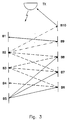
- Fig. 2 shows a sketch of the way the method of acknowledgement fundamentally functions according to the present invention in an sketched example, in which only one of the information modules B has a coverage for its means of acknowledgement such that the signal of acknowledgement reaches the unit A transmitting information.
- No power limits exists for the transmitting unit A which implies that the unit will have no problem in obtaining a coverage indicated by the shaded area, which covers all information modules, whereas the information modules B each have its own coverage marked by the circles, respectively.
- each of the modules B has a unique address and may thus be addressed by A.
- a remote module B marked by an arrow in fig.
- the data package includes three main groups of information, one of which is an address or ID indication, another of which is a portion of data information including, for instance, price information etc., and a third of which is an error check code CRC by means of which the information modules will be able to determine whether the message has been correctly received and decoded.
- the module B5 will establish that it constitutes itself the addressed module and will thereby switch to its second mode of function, while the other modules receiving the transmitted message correctly but finding themselves not addressed will switch to a third mode of function for period of time T r .
- B4 will not repeat the secondary pulse of acknowledgement from B6 in this case.
- B5 will not react to a signal from B6, B7 and B8, since B5 is not in the third mode of function.
- B3 will send a secondary pulse of acknowledgement, which again will reach also B6, B7 and B8 but as they fundamentally will not be in the third mode of function, since they have already detected a pulse of acknowledgement, they will not react anymore.
- B2 will send a pulse of acknowledgement which thereby will reach B7, B8, B9, and B10. Neither are B7 and B8 in the third mode of function and will thus not react.
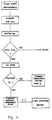
- the logical device of the information module will reset the module to its regular basic function, i.e. for receiving messages transmitted from the transmitting device TX.
- T r ⁇ 4 ms.
Abstract
Description
- The present invention relates to a method and a device for acknowledgement of transmitted price information in connection with electronic information modules for price marking, and particularly to a method and a device executing an acknowledgement of information transmitted to an information module, when an information module of the kind possesses a limited coverage for its signal of acknowledgement due to a limited supply of power.
- Today, systems, in which the price indicating items of information are stored in a central system computer, are introduced in greater department stores, which computer, in turn, provides the cash-point locations with price indicating items of information related to various articles. The cashier normally reads, usually by means of an optical reading device, a unique bar code, the so called EAN code, which is present on each article. Through this code the cash register thereby obtains the current price information of the article in question from the central system computer.
- Further a shelf-edge marking is applied at the location of each article, which marking states the name of the article and normally also a cost-per-unit price, e.g. the price per kilogram. Earlier, each article was usually provided also with a sticker stating the price and possibly a temporary discount price. In order to reduce the cost of such a price marking, effort is made, particularly in larger department stores, to leave out the individual price marking of each article, in which case the price marking is achieved only by means of shelf-edge marking at the storing place of each type of article.
- A further step in cost optimization includes electronic shelf-edge markings, which are controlled from the central system computer, thereby stating the price stored in the central system computer of the article in question. Through this, it will be ensured that the items of information of the price marking will correspond to the price charged to the customer at the cash-point, which obtains the price indicating items of information, just like the shelf-edge marking, from the central system computer. A type of such an electronic label system/signing system has been disclosed, e.g. in the Swedish patent SE 441 447 granted to S. Olsson and R. Ahlm in 1986 and assigned to the signer of the present application.
- A problem in connection with a system comprising such electronic devices of presentation, or "displays", when the communication to these devices is carried out in a wireless manner, e.g. through transmission by means of light, is to efficiently receive an acknowledgement confirming that the shelf-edge unit in question has received the transmitted information correctly. Firstly, such a price-marking unit may be blocked by a separate object preventing the information from reaching the unit in question, and, secondly, with a limited supply of power, its problematic to obtain a sufficient coverage for its means of response for enabling the transmission of an unambiguous reply implying that information transmitted to the particular unit has been received correctly.
- Common to such systems is that the transmission of information should be achieved wireless in order to obtain a flexible price-marking system. Thereby, the most applicable method of transmission is by means of light, suitably within the range of non-visible light, e.g. as IR light as used in prior art for various remote control devices to control electronic or electrical apparatuses, such as TV-sets etc.
- Such a system is disclosed, e.g. in the European patent document EP-A2-0 443 447. Here, a bi-directional system is disclosed, which optically signals back to the transmitting device directly or by reflection and scattering or by deflection. In the disclosed system, the electronic label/shelf-edge module will consist of a relatively complicated unit, since the acknowledgement system requires additional complex electronics, while the system will require a considerable control power, fundamentally necessitating each unit to be provided with a battery, which, thereby, will have to be exchanged regularly. This means considerable expenses for a larger shop data system possibly comprising 10 000 labels/information modules.
- Another document WO 91/07028 discloses a system for transmitting data between a number of participating units in a local communications network. The system utilizes at least two substations, which assist in transmitting binary data between the participant units in the network, transmitted data being pulse modulated and substations repeating each received partial pulse after a certain time delay. This system presents great limitations to the large number of participating units, which will be included in a shop data system having shelf-edge markings. In addition to the complexity of each substation, the system will require power levels for the responding units, which levels are higher than what is practically applicable in a flexible system for information devices in a shop.
- The invention relates to a method (claim 1), a shop data system (claim 9) and a module for use in a shop data system (claim 17) for acknowledgement of information transmitted by a device to a plurality of electronic label/information modules.
- A method is provided to increase the coverage of each individual information device, e.g. a shelf-edge module, having a low output power for its message acknowledgement at the reception of information, ensuring that an acknowledgement stating that information has been received reaches the system computer.
- According to the method, an information device, which has received a correctly decoded information intended for that particular module, emits a signal of acknowledgement, whereas at least one other module, which obtains the same information and thereby realizes that the message is not intended for the module in question, switches to a repeater mode, whereby the signal of acknowledgement emitted by the addressed module will be repeated by at least one other such module, which has perceived the signal of acknowledgement, whereby the signal of acknowledgement thus will propagate back to the transmitting device.
- According to a further aspect of the method, the transmitting device will wait for a certain period of time following the transmission of a message addressed to a specific module, at the time of which, as soon as a signal of acknowledgement, which has propagated directly or has been repeated by one or more modules unaddressed by the message in question, during this waiting period reaches the transmitting device, it will thereby be ensured that the thus addressed module will have received its information correctly, which will then be noted in the system computer, and it will thereby be ensured, e.g., that an information module having price marking displays the same information as that, which the cash-point register will charge a customer for the article, the price of which has been given by means of the information module in question.
- According to yet another aspect of the method, it is only required that each information module has a coverage for its signal of acknowledgement, such that it will reach at least one additional information module, which thereby will forward the signal of acknowledgement.
- Furthermore, a subsystem will be provided as well as a signalling device intended to be comprised in each information device to execute the signalling according to the method, the signalling device comprising an electromagnetic or light emitting source having a low power consumption making it possible to continuously energize the information module by means of a solar cell.
- The invention will now be described in the form of a preferred embodiment by means of the appended drawings, wherein:
- Fig. 1
- illustrates an embodiment of an information module for which the present invention is intended to be applied,
- Fig. 2
- illustrates an example of the way the total coverage is changed for the individual modules in the case where the coverage of at least one module includes the central receiver,
- Fig. 3
- illustrates in a simplified manner the principle of repetition of a signal of acknowledgement from an addressed module,
- Fig. 4
- illustrates a portion of the information module logic for acknowledgement of reception of an addressed message in the form of a simplified diagram,
- Fig. 5
- illustrates a simplified logical diagram for the information module, when it is set to a repeater mode, and
- Fig. 6
- illustrates as an embodiment a means of acknowledgement for transmitting or repeating a signal of acknowledgement.
- Fig. 1 shows as an embodiment an electronic label/information module in the form a shelf-edge device for price-marking articles and products in a department store, which module is intended to be equipped with an acknowledgement device according to the method of the present invention. The information module of Fig. 1 has a field of representation to the right in the form of an LCD display for presentation of various numerical items of information such as price, coat-per-unit price, regular price etc. It may also be used, for instance for non-public purposes, to show other information stored. Leftmost on the module, essentially a solar cell is provided, which supplies the module with electric power by means of the lighting present in the shop. Between the LCD display and the solar cell, a field is provided for the introduction of a standardized paper label having additional information about the article in question.
- Fig. 2 shows a sketch of the way the method of acknowledgement fundamentally functions according to the present invention in an sketched example, in which only one of the information modules B has a coverage for its means of acknowledgement such that the signal of acknowledgement reaches the unit A transmitting information. No power limits exists for the transmitting unit A, which implies that the unit will have no problem in obtaining a coverage indicated by the shaded area, which covers all information modules, whereas the information modules B each have its own coverage marked by the circles, respectively. Further, each of the modules B has a unique address and may thus be addressed by A. In the case where a remote module B (marked by an arrow in fig. 2) is addressed by the transmitting device A and this device acknowledges a correctly received message by transmitting a signal of acknowledgement, this signal of acknowledgement will not have a sufficient coverage due to power limitations as the module B will only be energized by a solar cell utilizing light existing in the premises. The addressed module B, which has been switched to a second mode of function upon the decoding of the data information received from A at the established correspondence of the ID or address, and which initiates a transmission of a pulse of acknowledgement intended for the unit A. In this case the addressed module B will thus, however, not be able to acknowledge its received message directly to A, since its coverage indicated by the circle line around B does not cover A. In fig. 2, it is only the functional module B closest to A, which has an area of coverage which includes A.
- According to the present invention, all other modules B, which have received the information transmitted by A and established that the address or ID did not correspond with their own addresses, are switched to a third mode of function. This mode has a function such that if the information module in this third mode perceives a signal of acknowledgment transmitted from another module, the logical circuitry of the module will initiate that a secondary signal of acknowledgement will be transmitted, upon which the module will switch back to its basic mode of function. Through this repeater mode by means of the other information modules, the module B of fig. 2, in this case, the addressed one, will thereby obtain an actual secondary coverage indicated by the dash line, and the acknowledgement of the received message may thus reach the unit A, which sent the information.
- Fig. 3 shows in a more detailed manner what happens at an acknowledgement according to the present system. The transmitting unit requiring an acknowledgement of a transmitted message is designated with the reference letters TX, while the information modules present in the example are designated with references B1 - B10, B5 being the addressed module. TX transmits a data package, which, in the preferred embodiment, consists of 216 bits, which are pulse-width modulated onto a IR light signal. This transmission takes place for period of time of the magnitude of 27 ms in the preferred embodiment, upon which TX is switched to a mode of reception for a period of time of 4 ms in the embodiment. In principle, the data package includes three main groups of information, one of which is an address or ID indication, another of which is a portion of data information including, for instance, price information etc., and a third of which is an error check code CRC by means of which the information modules will be able to determine whether the message has been correctly received and decoded. In the example of fig. 3, the module B5 will establish that it constitutes itself the addressed module and will thereby switch to its second mode of function, while the other modules receiving the transmitted message correctly but finding themselves not addressed will switch to a third mode of function for period of time Tr.
- After having been switched to the second mode of function, B5 will transmit a primary pulse of acknowledgement. In the preferred embodiment, this will be in the form of a single pulse having a length of the magnitude of 50 µs, but may in an additional embodiment comprise more than one pulse. After this, B5 will return to its basic mode of function. This pulse of acknowledgement will not be perceived by TX but will be detected by B6, B7 and B8, which in this situation are set to the third mode of function, and they will therefore each initiate transmission of a secondary pulse of acknowledgement, upon which they will return to their basic mode of function. In the embodiment, the secondary signal of acknowledgement, just like the primary pulse of acknowledgement, consists of a single pulse, which in the preferred embodiment has a length of about 14 µs, but which in an additional embodiment, just like the primary pulse of acknowledgement, may be composed by a number of different pulses. These secondary pulses of acknowledgement will be perceived by B4, B3 and B2, B3 and B2 further, in fact, obtaining pulses from several repeating modules. B3 obtains a signal from B6, B7 and B8, whereas B2 obtains a signal, from B7 and B8. Let us further assume that B4 in this case did not perceive the message transmitted to B5 correctly and consequently did not switch to the third mode of function. Consequently, B4 will not repeat the secondary pulse of acknowledgement from B6 in this case. B5 will not react to a signal from B6, B7 and B8, since B5 is not in the third mode of function. B3 will send a secondary pulse of acknowledgement, which again will reach also B6, B7 and B8 but as they fundamentally will not be in the third mode of function, since they have already detected a pulse of acknowledgement, they will not react anymore. B2 will send a pulse of acknowledgement which thereby will reach B7, B8, B9, and B10. Neither are B7 and B8 in the third mode of function and will thus not react. B9 and B10 will however be initiated to transmit a secondary pulse of acknowledgement, the pulse from B10 reaching TX, at which TX will obtain acknowledgement implying that the addressed module B5 has received its information correctly. Also B1 will transmit a secondary pulse of acknowledgement but no further module will react, since the modules B2 - B10 will have returned to their basic mode of function. B1 having transmitted its secondary pulse of acknowledgement, all modules will be in the basic mode of function and will themselves be ready to receive new information from TX and to acknowledge or to relay a signal of acknowledgement. This whole process will take place within a period of time smaller than Tr, this thus being the condition under which the signal from B10 is to be perceived by TX as a signal of acknowledgement from B5.
- Fig. 4 shows a fundamental logical diagram of the acknowledgement function according to the embodiment, when the information device is in the basic mode of function. The regular receiver device in the information module (not shown) receives signals transmitted by the central controlling transmitting device (TX in fig. 3). These signals are pulse-width demodulated, a signal value of 1 e.g. corresponding to a pulse width of 30 µs and a signal value of 0 corresponding a pulse width of 8 µs. The number of bits are counted in a counter until, in this case, all 216 bits have been registered. The data bits are buffered in a conventional manner according to prior art, the CRC code being checked as to its indication of a correct reception of the entire data package. Should it have been received incorrectly, STOP will be obtained and the data processing and the module will wait in their basic mode of function for a new data transmission. Should the CRC check indicate that the entire message has been received correctly, the ID code will be extracted and it will be checked whether or not the ID code corresponds to the ID of the information module in question. Should the ID or address be the correct one, the logical circuitry will then initiate a 50 µs voltage pulse, which will be applied to a light emitting device, which will emit an IR light pulse equal to the length of the applied voltage pulse, upon which the information module will return to the basic mode of function, i.e. wait for a new transmission of data information. The data information received will thereby be displayed according to prior art on the display of presentation.
- Should the ID or address not be the correct one, the logical circuitry will be set to a third mode, or a repeater mode. Fig. 5 shows in a simplified manner a logical diagram of the function, when the information module has been switched to the third mode of function. Should an adjacent module transmit a light pulse constituting a primary or a secondary signal of acknowledgement and should the receiving means of this module perceive this signal, a check will be made to investigate whether or not it is the first pulse after the setting of the third mode of function. Should it not be the first pulse, the logical circuitry will go to the STOP function, i.e. the module will switch back to the basic mode of function without taking any other action. Should the logical circuitry establish that this is the first signal of acknowledgement perceived, transmission of a secondary pulse of acknowledgement is initiated by applying in the embodiment a 14 µs voltage pulse to the light emitting device, which thereby will emit a light pulse corresponding thereto.
- Should the information module within a period of time Tr (Fig. 4) in the embodiment not have registered any primary or secondary light pulse constituting a signal of acknowledgement, the logical device of the information module will reset the module to its regular basic function, i.e. for receiving messages transmitted from the transmitting device TX. Thus, in the embodiment Tr < 4 ms.
- TX will thus transmit for a maximum of approximately 27 ms in the preferred embodiment, upon which it will wait for a signal of acknowledgement for the subsequent approximately 4 ms. Should a signal of acknowledgement be obtained within this period of time, the system computer monitoring the shop data system will thereby have obtained an indication implying that the information module in question has obtained the intended information. Should no acknowledgement be obtained, the system computer will know, guided by the address, exactly which information module and thus which article will not have received new information, and in this way it will be ensured that the items of information assigned by the system computer to the cash-points will correspond to, for instance, the price indicating items of information indicated by an information module. By conventionally interrogating the system computer, information will be obtained as to which modules do not respond to a repeated transmission at a certain time, and it will thus be easy to investigate whether, for instance, this information module has been, e.g., blocked or whether any other abnormal condition has occurred.
- Figure 6. shows a preferred embodiment of the light emitting device comprising only a standard CMOS type field effect transistor T having a high input impedance on the gate electrode, an IR emitting light diode, a capacitor battery C and a resistor R. The capacitor C, which may be constituted by one or more capacitors depending on the insertion space in the information module, is charged from a solar cell through the resistor R, which has a high value of resistance to adapt the load on the solar cell. A voltage pulse from the logical circuitry is input to the gate of the transistor T at initiation of a primary or secondary signal of acknowledgment. During the period of time, under which the input voltage pulse is high, the line channel of the transistor will be completely opened, thus permitting current to flow through the diode D from the capacitor battery C. Since the pulse duration is short, 50 or 14 µs, the capacitor battery will not have time to discharge completely, while, further, the capacitor battery will continuously obtain a small charging power through the resistor R from the solar cell. Through the arrangement with the capacitor battery, a considerably greater power than normally provided by the solar cell may thus be momentarily extracted for a limited period of time, but the total energy integrated by the capacitor battery will be more than sufficient.
- According to the present invention, the coverage of each individual information module only has to amount to 3 - 4 m, while a coverage many times greater than this value and more than enough to cover the distances, which may exist in shop premises, will be obtained through the method of repetition.
- In the description, a preferred embodiment has been discussed. The electronic implementation of the logical functions discussed may be realized in various ways according to what is already well-known to a person skilled in the art and has thus been excluded from a detailed description. As to the circuitry, the method and device according to the present invention may in connection herewith be realized in a number of different electronic embodiments within the scope of the claims stated below.
Claims (22)
- A method for acknowledgement of information transmitted by a transmitting device (A) in a shop data system to a plurality of electronic label/information modules (B1-B10)
comprising the steps of:the method being characterised by the steps of:transmitting information including address and data from said transmitting device (A);decoding said information at at least one electronic label/information module (B5) of said plurality of electronic label/information modules (B1-B10);generating at, and transmitting from, said at least one electronic label/information module (B5) an acknowledgement signal when said information is correctly decoded;switching at least one other electronic label/information module of said plurality of electronic label/information modules (B1-4, B6-10) to a repeater mode; andrepeating said acknowledgement signal at said at least one other electronic label/information module(s) (B1-4, B6-10) when in said repeater mode. - The method according to claim 1, characterised in thatsaid switching to a repeater mode is automatically initiated at said at least one other electronic label/information module(s) (B1-4, B6-10) once said module (B1-4, B6-10) has decoded said information and established that the address did not correspond to its own address.
- The method according to claims 1 or 2, characterised in thatsaid at least one other electronic label/information module(s) (B1-4, B6-10) returns from its repeater mode if said module (B1-4, B6-10) does not detect any direct or repeated acknowledgement signal after a period of time (Tr) smaller than the period of time between two consecutive transmissions of information from said transmitting device (A).
- The method according to anyone of claims 1-3, characterised in thatsaid acknowledgement signal consists of electromagnetic pulses.
- The method according to anyone of claims 1-3, characterised in thatsaid acknowledgement signal consists of a single electromagnetic pulse.
- The method according to anyone of claims 1-3, characterised in thatsaid repeated acknowledgement signal consists of electromagnetic pulses.
- The method according to anyone of claims 1-3, characterised in thatsaid repeated acknowledgement signal consists of a single electromagnetic pulse.
- The method according to anyone of claims 4-7, characterised in thatsaid direct or repeated signal of acknowledgement consists of at least one light pulse in the IR range, which is created by a pulse of electric voltage, which is applied to a light emitting diode or LED.
- A shop data system for acknowledgement of information comprising a transmitting device (A) and a plurality of electronic label/information modules (B1-B10), said transmitting device (A) transmitting information including address and data, at least one of said electronic label/information modules (B5) comprising decoding means for decoding said information and generating means for generating an acknowledgement signal when said information is correctly decoded;
characterised in thatat least one other of said plurality electronic label/information modules (B1-4, B6-10) is provided with;switching means for switching said at least one other electronic label/information module (B1-4, B6-10) to a repeater mode; andrepeating means for repeating said acknowledgement signal at said at least one other electronic label/information module (B1-4, B6-10) when in said repeater mode. - The shop data system according to claim 9, characterised in thatsaid at least one other electronic label/information module (B1-4, B6-10) is further provided with decoding means for decoding said information; andsaid switching to a repeater mode is adapted to be automatically initiated at said at least one other electronic label/information module(s) (B1-4, B6-10) once said module (B1-4, B6-10) has decoded said information and established that the address did not correspond to its own address.
- The shop data system according to claims 9 or 10, characterised in thatsaid at least one other electronic label/information module(s) (B1-4, B6-10) is adapted to return from its repeater mode if said module (B1-4, B6-10) does not detect any direct or repeated acknowledgement signal after a period of time (Tr) smaller than the period of time between two consecutive transmissions of information from said transmitting device (A).
- The shop data system according to anyone of claims 9-11, characterised in thatsaid acknowledgement signal consists of electromagnetic pulses.
- The shop data system according to anyone of claims 9-11, characterised in thatsaid acknowledgement signal consists of a single electromagnetic pulse.
- The shop data system according to anyone of claims 9-11, characterised in thatsaid repeated acknowledgement signal consists of electromagnetic pulses.
- The shop data system according to anyone of claims 9-11, characterised in thatsaid repeated acknowledgement signal consists of a single electromagnetic pulse.
- The shop data system according to anyone of claims 12-15, characterised in thatsaid signal of direct or repeated acknowledgement consists of at least one light pulse in the IR range, which is created by a pulse of electric voltage, which is applied to a light emitting diode or LED.
- An electronic label/information module (B1-B10) for use in a shop data system,said module receiving information including address and data from a transmitting device of said shop data system and acknowledgement signals from other electronic label/information modules within said shop data system, said module comprising decoding means for decoding said information and generating means for generating an acknowledgement signal when said information is correctly decoded,
characterised byswitching means for switching said module to a repeater mode; andrepeating means for repeating, when in said repeater mode, an acknowledgement signal from one other electronic label/information module. - The electronic label/information module according to claim 17, characterised in thatsaid switching to a repeater mode is adapted to be automatically initiated once said module has decoded said information and established that the address did not correspond to its own address.
- The electronic label/information module according to claims 17 or 18, characterised in thatsaid module is adapted to return from its repeater mode if said module does not detect any direct or repeated acknowledgement signal after a period of time (Tr) smaller than the period of time between two consecutive transmissions of information from said transmitting device (A).
- The electronic label/information module according to anyone of claims 17-19, characterised in thatsaid repeated acknowledgement signal consists of electromagnetic pulses.
- The electronic label/information module according to anyone of claims 17-19, characterised in thatsaid repeated acknowledgement signal consists of a single electromagnetic pulse.
- The electronic label/information module according to anyone of claims 17-21, characterised in thatsaid repeated acknowledgement signal consists of at least one light pulse in the IR range, which is created by a pulse of electric voltage, which is applied to a light emitting diode or LED.
Applications Claiming Priority (3)
| Application Number | Priority Date | Filing Date | Title |
|---|---|---|---|
| SE9203339 | 1992-11-09 | ||
| SE9203339A SE470518B (en) | 1992-11-09 | 1992-11-09 | Procedure and apparatus for receipt of information |
| PCT/SE1993/000935 WO1994011832A1 (en) | 1992-11-09 | 1993-11-08 | Method and device for acknowledgement of transmitted information |
Publications (2)
| Publication Number | Publication Date |
|---|---|
| EP0667971A1 EP0667971A1 (en) | 1995-08-23 |
| EP0667971B1 true EP0667971B1 (en) | 2000-09-20 |
Family
ID=20387749
Family Applications (1)
| Application Number | Title | Priority Date | Filing Date |
|---|---|---|---|
| EP93924880A Expired - Lifetime EP0667971B1 (en) | 1992-11-09 | 1993-11-08 | Method and device for acknowledgement of transmitted information |
Country Status (7)
| Country | Link |
|---|---|
| US (1) | US5729695A (en) |
| EP (1) | EP0667971B1 (en) |
| JP (1) | JP3466188B2 (en) |
| AU (1) | AU5438494A (en) |
| DE (1) | DE69329463D1 (en) |
| SE (1) | SE470518B (en) |
| WO (1) | WO1994011832A1 (en) |
Families Citing this family (23)
| Publication number | Priority date | Publication date | Assignee | Title |
|---|---|---|---|---|
| FR2725813A3 (en) * | 1994-10-17 | 1996-04-19 | Topcard Monetique Sa | METHOD FOR OPERATING A DATA MEDIUM, PORTABLE OBJECT AND MANAGEMENT SYSTEM USING THE OPERATING METHOD |
| FR2726709B1 (en) * | 1994-10-17 | 1997-07-04 | Topcard Monetique Sa | METHOD FOR OPERATING AT LEAST ONE PORTABLE OBJECT IN A MULTI-USER OPERATING SYSTEM AND SUCH A SYSTEM |
| US5604923A (en) * | 1994-11-15 | 1997-02-18 | At&T Global Information Solutions Company | Electronic display system capable of displaying communication signal strength on individual electronic display modules and method of using the same |
| US5722048A (en) * | 1994-12-02 | 1998-02-24 | Ncr Corporation | Apparatus for improving the signal to noise ratio in wireless communication systems through message pooling and method of using the same |
| US6269342B1 (en) * | 1995-04-28 | 2001-07-31 | Telxon Corporation | Programmable shelf tag system |
| US5751257A (en) | 1995-04-28 | 1998-05-12 | Teletransactions, Inc. | Programmable shelf tag and method for changing and updating shelf tag information |
| US6055414A (en) * | 1996-07-23 | 2000-04-25 | Ncr Corporation | System and method for improving reliability and performance of wireless communication systems using message pooling |
| SE513077C2 (en) * | 1998-05-15 | 2000-07-03 | Pricer Ab | Method for controlling energy use in an electronic label and remote controlled electronic label |
| DE19821966A1 (en) * | 1998-05-17 | 1999-11-18 | Systec Ausbausysteme Gmbh | Distribution of information in a self service store |
| US7005985B1 (en) * | 1999-07-20 | 2006-02-28 | Axcess, Inc. | Radio frequency identification system and method |
| AU6096200A (en) * | 1999-07-20 | 2001-02-05 | Axcess Inc. | Radio frequency identification system and method |
| DE19956615A1 (en) * | 1999-11-25 | 2001-05-31 | Barbara Jost | Shopping trolley has information system with readers of data stored on card and graphical, especially bar code, data; data read are transmitted/received to/from shop computer and displayed |
| DE10102196A1 (en) * | 2001-01-18 | 2002-07-25 | Printoplast Ag Affoltern | Price display system, for sales areas, has a plastic rail system on each shelf containing indicators, transceivers and solar modules connecting to a central preparation system |
| JP2003243996A (en) | 2002-02-18 | 2003-08-29 | Seiko Instruments Inc | Data telegraphic transmitter |
| US7881711B2 (en) * | 2002-07-08 | 2011-02-01 | Qualcomm Incorporated | Feedback system using dynamic decoding |
| US8061600B2 (en) * | 2003-12-18 | 2011-11-22 | Altierre Corporation | Wireless display tag |
| US7841120B2 (en) | 2004-03-22 | 2010-11-30 | Wilcox Industries Corp. | Hand grip apparatus for firearm |
| US20070016460A1 (en) * | 2005-07-14 | 2007-01-18 | Vocollect, Inc. | Task management system having selectively variable check data |
| US20070205896A1 (en) * | 2006-03-02 | 2007-09-06 | Axcess International Inc. | System and Method for Determining Location, Directionality, and Velocity of RFID Tags |
| US20070285241A1 (en) * | 2006-03-20 | 2007-12-13 | Axcess International Inc. | Multi-Tag Tracking Systems and Methods |
| WO2007133690A2 (en) * | 2006-05-11 | 2007-11-22 | Axcess International Inc. | Radio frequency identification (rfid) tag antenna design |
| US8638194B2 (en) * | 2008-07-25 | 2014-01-28 | Axcess International, Inc. | Multiple radio frequency identification (RFID) tag wireless wide area network (WWAN) protocol |
| CN102131429A (en) * | 2008-08-21 | 2011-07-20 | 精工电子数据服务有限公司 | Electronic shelf label system, communication control device, relay station device, electronic shelf label information distribution method, and program |
Family Cites Families (12)
| Publication number | Priority date | Publication date | Assignee | Title |
|---|---|---|---|---|
| SE8405140L (en) * | 1984-10-15 | 1985-10-07 | Makoson Ab | SHELF EDGE LABELING DEVICE |
| US4879756A (en) * | 1986-09-22 | 1989-11-07 | Stevens John K | Radio broadcast communication systems |
| US4821291A (en) * | 1986-09-22 | 1989-04-11 | Stevens John K | Improvements in or relating to signal communication systems |
| US4888709A (en) * | 1987-03-27 | 1989-12-19 | Viscom Systems, Inc. | Electronic product information display system |
| US5198644A (en) * | 1989-05-05 | 1993-03-30 | Diablo Research Corporation | System for display of prices and related method |
| DE3937096A1 (en) * | 1989-11-07 | 1991-05-08 | Siemens Nixdorf Inf Syst | SYSTEM FOR TRANSMITTING DATA BETWEEN SEVERAL SUBSCRIBER STATIONS OF A LOCAL COMMUNICATION NETWORK |
| DE4005517A1 (en) * | 1990-02-22 | 1991-09-05 | Sensys Ag | Bidirectional signal transmission system using IR light - has identical devices for simultaneous transmission in both directions |
| US5563728A (en) * | 1991-02-22 | 1996-10-08 | Allen; Richard C. | Infrared communication repeater architecture |
| DK52091D0 (en) * | 1991-03-22 | 1991-03-22 | Esel Krabbe Systems As | INFORMATION |
| US5379229A (en) * | 1992-06-18 | 1995-01-03 | Communications Test Design, Inc. | Automated storage and retrieval system |
| FR2703537B1 (en) * | 1993-04-02 | 1995-06-09 | Sextant Avionique | Method for the transmission of information over the air. |
| US5412654A (en) * | 1994-01-10 | 1995-05-02 | International Business Machines Corporation | Highly dynamic destination-sequenced destination vector routing for mobile computers |
-
1992
- 1992-11-09 SE SE9203339A patent/SE470518B/en not_active IP Right Cessation
-
1993
- 1993-11-08 WO PCT/SE1993/000935 patent/WO1994011832A1/en active IP Right Grant
- 1993-11-08 DE DE69329463T patent/DE69329463D1/en not_active Expired - Lifetime
- 1993-11-08 US US08/432,187 patent/US5729695A/en not_active Expired - Lifetime
- 1993-11-08 EP EP93924880A patent/EP0667971B1/en not_active Expired - Lifetime
- 1993-11-08 JP JP51198494A patent/JP3466188B2/en not_active Expired - Lifetime
- 1993-11-08 AU AU54384/94A patent/AU5438494A/en not_active Abandoned
Also Published As
| Publication number | Publication date |
|---|---|
| JP3466188B2 (en) | 2003-11-10 |
| AU5438494A (en) | 1994-06-08 |
| WO1994011832A1 (en) | 1994-05-26 |
| DE69329463D1 (en) | 2000-10-26 |
| JPH08503795A (en) | 1996-04-23 |
| SE9203339L (en) | 1994-05-10 |
| US5729695A (en) | 1998-03-17 |
| SE9203339D0 (en) | 1992-11-09 |
| SE470518B (en) | 1994-06-27 |
| EP0667971A1 (en) | 1995-08-23 |
Similar Documents
| Publication | Publication Date | Title |
|---|---|---|
| EP0667971B1 (en) | Method and device for acknowledgement of transmitted information | |
| CN1941017B (en) | Method of communication and home automation installation for its implementation | |
| EP0427342B1 (en) | Transmission system | |
| EP0685825B1 (en) | Electronic identification system | |
| US5751223A (en) | Electronic identification system | |
| CA2128596C (en) | Arrangement for simultaneously interrogating a plurality of portable radio frequency communication devices | |
| US4766295A (en) | Electronic pricing display system | |
| GB2244359A (en) | Electronic display system | |
| US4176401A (en) | Digital communications system | |
| NL9001318A (en) | SYSTEM FOR DETECTING THE PRESENCE IN A RACK OF A PORTABLE UNIT SUITABLE FOR TRANSMITTING OR RECEIVING A SIGNAL WITH AN ASSIGNED IDENTIFICATION NUMBER. | |
| GB2197564A (en) | Radio broadcast communication systems | |
| EP0423188A1 (en) | Arrangement for marking system. | |
| CA1121893A (en) | High speed central office scanner | |
| US8565611B2 (en) | Optically-connected system for exchanging data among industrial automation devices | |
| EP0459659A1 (en) | Labelling system | |
| WO1994011833A1 (en) | Monitoring module | |
| WO1994011834A1 (en) | Receiver polling | |
| GB2231994A (en) | Information display system | |
| EP0289253B1 (en) | System and method for controlling terminal equipment | |
| WO1995023389A1 (en) | Method and device for acknowledgement | |
| US3495218A (en) | Data transmitting system utilizing shift registers and line relays | |
| JPH10224301A (en) | Method and device for auction by optical space transmission | |
| EP0241148A1 (en) | Data transfer system | |
| EP0114985B1 (en) | System for interfacing remote functional units to a terminal unit | |
| SE500644C2 (en) | Display system involving information and follow-up for data presention in shops, warehouses, etc. - involves one or more indicating information carriers with programmable basic information which is alterable via connection with one or more receivers |
Legal Events
| Date | Code | Title | Description |
|---|---|---|---|
| PUAI | Public reference made under article 153(3) epc to a published international application that has entered the european phase |
Free format text: ORIGINAL CODE: 0009012 |
|
| AK | Designated contracting states |
Kind code of ref document: A1 Designated state(s): DE ES FR GB IT |
|
| 17P | Request for examination filed |
Effective date: 19950515 |
|
| 17Q | First examination report despatched |
Effective date: 19980709 |
|
| RAP1 | Party data changed (applicant data changed or rights of an application transferred) |
Owner name: PRICER AKTIEBOLAG |
|
| RIC1 | Information provided on ipc code assigned before grant |
Free format text: 6G 06F 17/00 A, 6G 06F 17/60 B, 6G 07G 1/14 B, 6G 06K 17/00 B, 6A 47F 10/02 B, 6H 04B 10/10 B |
|
| RIC1 | Information provided on ipc code assigned before grant |
Free format text: 6G 06F 17/00 A, 6G 06F 17/60 B, 6G 07G 1/14 B, 6G 06K 17/00 B, 6A 47F 10/02 B, 6H 04B 10/10 B |
|
| GRAG | Despatch of communication of intention to grant |
Free format text: ORIGINAL CODE: EPIDOS AGRA |
|
| 17Q | First examination report despatched |
Effective date: 19980709 |
|
| GRAG | Despatch of communication of intention to grant |
Free format text: ORIGINAL CODE: EPIDOS AGRA |
|
| GRAH | Despatch of communication of intention to grant a patent |
Free format text: ORIGINAL CODE: EPIDOS IGRA |
|
| GRAH | Despatch of communication of intention to grant a patent |
Free format text: ORIGINAL CODE: EPIDOS IGRA |
|
| GRAA | (expected) grant |
Free format text: ORIGINAL CODE: 0009210 |
|
| AK | Designated contracting states |
Kind code of ref document: B1 Designated state(s): DE ES FR GB IT |
|
| PG25 | Lapsed in a contracting state [announced via postgrant information from national office to epo] |
Ref country code: IT Free format text: LAPSE BECAUSE OF FAILURE TO SUBMIT A TRANSLATION OF THE DESCRIPTION OR TO PAY THE FEE WITHIN THE PRESCRIBED TIME-LIMIT;WARNING: LAPSES OF ITALIAN PATENTS WITH EFFECTIVE DATE BEFORE 2007 MAY HAVE OCCURRED AT ANY TIME BEFORE 2007. THE CORRECT EFFECTIVE DATE MAY BE DIFFERENT FROM THE ONE RECORDED. Effective date: 20000920 Ref country code: FR Free format text: LAPSE BECAUSE OF FAILURE TO SUBMIT A TRANSLATION OF THE DESCRIPTION OR TO PAY THE FEE WITHIN THE PRESCRIBED TIME-LIMIT Effective date: 20000920 Ref country code: ES Free format text: THE PATENT HAS BEEN ANNULLED BY A DECISION OF A NATIONAL AUTHORITY Effective date: 20000920 |
|
| REF | Corresponds to: |
Ref document number: 69329463 Country of ref document: DE Date of ref document: 20001026 |
|
| PG25 | Lapsed in a contracting state [announced via postgrant information from national office to epo] |
Ref country code: DE Free format text: LAPSE BECAUSE OF FAILURE TO SUBMIT A TRANSLATION OF THE DESCRIPTION OR TO PAY THE FEE WITHIN THE PRESCRIBED TIME-LIMIT Effective date: 20001221 |
|
| EN | Fr: translation not filed | ||
| PLBE | No opposition filed within time limit |
Free format text: ORIGINAL CODE: 0009261 |
|
| STAA | Information on the status of an ep patent application or granted ep patent |
Free format text: STATUS: NO OPPOSITION FILED WITHIN TIME LIMIT |
|
| 26N | No opposition filed | ||
| PGFP | Annual fee paid to national office [announced via postgrant information from national office to epo] |
Ref country code: GB Payment date: 20011025 Year of fee payment: 9 |
|
| REG | Reference to a national code |
Ref country code: GB Ref legal event code: IF02 |
|
| PG25 | Lapsed in a contracting state [announced via postgrant information from national office to epo] |
Ref country code: GB Free format text: LAPSE BECAUSE OF NON-PAYMENT OF DUE FEES Effective date: 20021108 |
|
| GBPC | Gb: european patent ceased through non-payment of renewal fee |