EP0667715A2 - Apparatus and methods for transmitting compressed digital data from recording or reproducing apparatus - Google Patents
Apparatus and methods for transmitting compressed digital data from recording or reproducing apparatus Download PDFInfo
- Publication number
- EP0667715A2 EP0667715A2 EP95300896A EP95300896A EP0667715A2 EP 0667715 A2 EP0667715 A2 EP 0667715A2 EP 95300896 A EP95300896 A EP 95300896A EP 95300896 A EP95300896 A EP 95300896A EP 0667715 A2 EP0667715 A2 EP 0667715A2
- Authority
- EP
- European Patent Office
- Prior art keywords
- data
- image data
- operative
- digital image
- recording
- Prior art date
- Legal status (The legal status is an assumption and is not a legal conclusion. Google has not performed a legal analysis and makes no representation as to the accuracy of the status listed.)
- Granted
Links
Images


Classifications
-
- H—ELECTRICITY
- H04—ELECTRIC COMMUNICATION TECHNIQUE
- H04N—PICTORIAL COMMUNICATION, e.g. TELEVISION
- H04N9/00—Details of colour television systems
- H04N9/79—Processing of colour television signals in connection with recording
- H04N9/80—Transformation of the television signal for recording, e.g. modulation, frequency changing; Inverse transformation for playback
- H04N9/804—Transformation of the television signal for recording, e.g. modulation, frequency changing; Inverse transformation for playback involving pulse code modulation of the colour picture signal components
- H04N9/8042—Transformation of the television signal for recording, e.g. modulation, frequency changing; Inverse transformation for playback involving pulse code modulation of the colour picture signal components involving data reduction
-
- H—ELECTRICITY
- H04—ELECTRIC COMMUNICATION TECHNIQUE
- H04N—PICTORIAL COMMUNICATION, e.g. TELEVISION
- H04N9/00—Details of colour television systems
- H04N9/79—Processing of colour television signals in connection with recording
- H04N9/80—Transformation of the television signal for recording, e.g. modulation, frequency changing; Inverse transformation for playback
- H04N9/804—Transformation of the television signal for recording, e.g. modulation, frequency changing; Inverse transformation for playback involving pulse code modulation of the colour picture signal components
- H04N9/806—Transformation of the television signal for recording, e.g. modulation, frequency changing; Inverse transformation for playback involving pulse code modulation of the colour picture signal components with processing of the sound signal
- H04N9/8063—Transformation of the television signal for recording, e.g. modulation, frequency changing; Inverse transformation for playback involving pulse code modulation of the colour picture signal components with processing of the sound signal using time division multiplex of the PCM audio and PCM video signals
-
- H—ELECTRICITY
- H04—ELECTRIC COMMUNICATION TECHNIQUE
- H04N—PICTORIAL COMMUNICATION, e.g. TELEVISION
- H04N5/00—Details of television systems
- H04N5/76—Television signal recording
- H04N5/78—Television signal recording using magnetic recording
- H04N5/782—Television signal recording using magnetic recording on tape
- H04N5/7824—Television signal recording using magnetic recording on tape with rotating magnetic heads
- H04N5/7826—Television signal recording using magnetic recording on tape with rotating magnetic heads involving helical scanning of the magnetic tape
- H04N5/78263—Television signal recording using magnetic recording on tape with rotating magnetic heads involving helical scanning of the magnetic tape for recording on tracks inclined relative to the direction of movement of the tape
- H04N5/78266—Television signal recording using magnetic recording on tape with rotating magnetic heads involving helical scanning of the magnetic tape for recording on tracks inclined relative to the direction of movement of the tape using more than one track for the recording of one television field or frame, i.e. segmented recording
-
- H—ELECTRICITY
- H04—ELECTRIC COMMUNICATION TECHNIQUE
- H04N—PICTORIAL COMMUNICATION, e.g. TELEVISION
- H04N5/00—Details of television systems
- H04N5/76—Television signal recording
- H04N5/91—Television signal processing therefor
- H04N5/917—Television signal processing therefor for bandwidth reduction
- H04N5/919—Television signal processing therefor for bandwidth reduction by dividing samples or signal segments, e.g. television lines, among a plurality of recording channels
-
- H—ELECTRICITY
- H04—ELECTRIC COMMUNICATION TECHNIQUE
- H04N—PICTORIAL COMMUNICATION, e.g. TELEVISION
- H04N9/00—Details of colour television systems
- H04N9/79—Processing of colour television signals in connection with recording
- H04N9/80—Transformation of the television signal for recording, e.g. modulation, frequency changing; Inverse transformation for playback
- H04N9/82—Transformation of the television signal for recording, e.g. modulation, frequency changing; Inverse transformation for playback the individual colour picture signal components being recorded simultaneously only
- H04N9/8205—Transformation of the television signal for recording, e.g. modulation, frequency changing; Inverse transformation for playback the individual colour picture signal components being recorded simultaneously only involving the multiplexing of an additional signal and the colour video signal
- H04N9/8233—Transformation of the television signal for recording, e.g. modulation, frequency changing; Inverse transformation for playback the individual colour picture signal components being recorded simultaneously only involving the multiplexing of an additional signal and the colour video signal the additional signal being a character code signal
- H04N9/8244—Transformation of the television signal for recording, e.g. modulation, frequency changing; Inverse transformation for playback the individual colour picture signal components being recorded simultaneously only involving the multiplexing of an additional signal and the colour video signal the additional signal being a character code signal involving the use of subcodes
Definitions
- the present invention relates to apparatus and methods for transmitting compressed digital data, such as digital image and audio data, from a recording or reproducing apparatus to other apparatus.
- Digital VTR's have been implemented for recording and reproducing standard definition (SD) digital video and audio signals on magnetic tape. Such VTR's carry out compression of the video signal in order to reduce the amount of data which must be recorded.
- SD standard definition
- HD video systems Digital high definition (HD) video systems have been proposed which would provide pictures having much higher resolution than SD systems.
- Implementation of HD digital video systems would require that HD digital VTR's be provided for recording and editing HD digital video data.
- apparatus and methods for reproducing digital image data, comprising the means for and the steps of, respectively: simultaneously reproducing a first portion of the digital image data in a first track of a recording medium and a second portion of the digital image data in a second track of the recording medium, the first and second tracks each storing a predetermined amount of data therein; multiplexing the first and second portions of the image data on a time-divisional basis in block data units to produce multiplexed image data, each of the block data units including an amount of data which is less than the predetermined amount of data stored in either of the first and second tracks; and providing the multiplexed image data to a transmission line.
- apparatus and methods for recording digital image data on a recording medium, comprising the means for and the steps of, respectively: receiving digital image data from a transmission line, the received digital image data including first and second data portions which have been time-division multiplexed in predetermined block units; demultiplexing the digital image data to supply the first data portion in a first data channel and the second data portion in a second data channel; and recording the first data portion in a first track in the recording medium and the second data portion in a second track in the recording medium, each of the first and second tracks recording an amount of data greater than an amount of data in each of the predetermined block units.
- apparatus and methods for recording digital image data, comprising the means for and the steps of, respectively: receiving a first portion of digital image data from a first data channel and a second portion of digital image data from a second data channel; recording the first portion of the digital image data in a first track in a recording medium and the second portion of the digital image data in a second track in the recording medium, each of the first and second tracks recording a predetermined amount of data therein; multiplexing the first and second portions of the digital image data on a time-divisional basis in block data units to produce multiplexed image data, each of the block data units including an amount of data which is less than the predetermined amount of data stored in either of the first and second tracks; and providing the multiplexed image data to a transmission line.
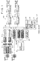
- a recording apparatus in accordance with a first embodiment of the present invention is illustrated in block form therein.
- the recording apparatus of Fig. 1 serves to record selectively either HD digital image signals or SD digital image signals in slant tracks on a magnetic tape, together with audio and subcode data in respective regions of each track.
- the apparatus of Fig. 1 splits the signal into first and second portions which it supplies to first and second channels, respectively, for processing and recording, each channel including corresponding processing circuitry designated respectively "-1" and "-2" in Fig. 1.
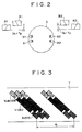
- Channel 1 supplies HD digital image data to a pair of magnetic recording heads A1 and A2 arranged at diametrically opposed positions on a rotating drum D, as illustrated schematically in Fig. 2.
- Channel 2 supplies HD digital image data to a pair of heads B1 and B2 also arranged at diametrically opposed positions on the rotating drum D.
- Heads A1 and B1 are positioned closely adjacent to one another on the drum D at respective levels spaced by a distance D s so that they simultaneously record tracks on a magnetic tape (not shown for purposes of simplicity and clarity) having a track pitch T p equal to the distance D s .
- Heads A1 and B1 also have respectively different azimuth angles.
- the heads A2 and B2 are arranged adjacent to one another at respectively different levels on the drum D separated by the distance D s , so that they simultaneously record tracks having a track pitch T p .
- heads A2 and B2 have respectively different azimuth angles. Accordingly, the HD digital image data is separated into two channels, each of which is recorded at a respective track on magnetic tape simultaneously with the data of the other channel in an adjacent parallel track.
- the apparatus of Fig. 1 For recording SD digital image data, the apparatus of Fig. 1 utilizes only one of the channels 1 or 2 for recording, so that the SD image signal is recorded in half the number of tracks per unit time as the HD signal.
- the recording apparatus of Fig. 1 also records digital audio and subcode data in each track.
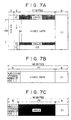
- Fig. 3 a schematic representation of the parallel tracks formed on a magnetic tape T by the apparatus of Fig. 1 is illustrated therein. It will be seen from Fig. 3 that the image or video signals are recorded in a central region of each track, and that the audio and subcode data are recorded in respective regions of each track on opposite sides of the video data region.
- each frame of the image data is recorded in N adjacent tracks on the magnetic tape T.
- the drum D rotates at a rate of 150 revolutions per second. Accordingly, when the apparatus of Fig. 1 is used to record SD digital image signals according to the 525 line per frame and 60 field per second system (525/60), each frame is recorded in ten tracks. When recording SD digital image signals according to the 625/50 system, each frame is recorded in twelve tracks. However, when the apparatus of Fig.
- each frame is recorded in twenty tracks, while in recording HD signals according to the 1250/50 system, each frame is recorded in twenty-four tracks.
- the apparatus of Fig. 1 divides the HD signals into two separate tracks and simultaneously records two tracks of data, it is possible to employ relatively slower, and less expensive processing circuitry.
- the head drum may be rotated at a standard speed of 150 revolutions per second both for recording SD and HD digital image signals. It will be appreciated that the recording apparatus of Fig. 1 thus employs relatively inexpensive circuitry for processing the signals to be recorded, as well as a relatively simple head drum servo system.
- An analog video signal which may be either an HD or SD signal, is received at a Video In terminal and is converted to digital form by an A/D converter 1 which outputs only those portions of the digital data representing the image itself to a blocking and shuffling circuit 2.
- the circuit 2 divides the received data into blocks (referred to herein as "DCT blocks") each representing a respective image area including eight samples in a horizontal image direction and eight lines in a vertical image direction.
- the DCT blocks are assembled into macroblocks each including four luminance DCT blocks and two color difference DCT blocks. Each DCT block is later transformed by discrete cosine transformation, as explained below.
- the macroblocks are then shuffled by the circuit 2 by grouping together five macroblocks from diverse areas of the image to form respective buffering units. This helps maintain a substantially uniform image resolution throughout each frame, as explained in greater detail below.
- Fig. 4A represents an image of a landscape depicting a sky 100 in the background and a region of foliage 102 in the foreground. It is assumed for the purposes of this explanation that a first group of five macroblocks 104 representing a portion of the sky background and a second group of five macroblocks 106 depicting a portion of the foliage in the foreground are extracted from the data representing this image. After discrete cosine transformation the amount of data in each of the five macroblocks within the group 104, indicated as macroblocks MB1 through MB5 typically would be relatively low as indicated in Fig. 4B.
- the amount of data in these macroblocks after discrete cosine transformation typically would be much larger, as indicated therein.
- the macroblocks are assembled into buffer units of a predetermined number of macroblocks and are then requantized as explained below, so that the amount of data in each buffer unit is then substantially uniform.
- each frame 108 of the image signal is divided into super macroblock regions 110, each of which includes 27 macroblocks.
- the super macroblocks are arranged generally in five vertical columns.
- the macroblocks are grouped in buffer units of five macroblocks 112 in accordance with a shuffling process by choosing each of the five macroblocks from a different one of five super macroblocks, one each from a different column and each of which spaced from the others in this example by two rows of super macroblocks.
- a further set of five macroblocks is selected in order to form twenty-seven further buffer units in the foregoing manner.
- the five new macroblocks are selected as those five super macroblocks immediately below the five super macroblocks from which the preceding twenty-seven buffer units were formed, provided that once the macroblocks of a super macroblock at the bottom of a column have been read out to form buffer units, the next super macroblock selected from that column is the uppermost.
- the shuffling process for HD image signals is similar to that for the SD image signals.
- the shuffled macro blocks are then subjected to discrete cosine transformation by a pair of DCT circuits 3-1 and 3-2.
- the blocks of each macroblock are supplied by the circuit 2 to a respective one of the DCT circuits 3-1 and 3-2 so that the data are distributed between the first and second channels.
- the macroblocks are fed in order as shuffled to only one of the channels, for example, channel 1, while the other channel is not used.
- each macroblock is subjected to requantization which is performed by the encoding circuits 4-1 and 4-2 in the case of the HD signal.
- Requantization is carried out by selecting a quantization step size for each macroblock so that substantially the same amount of data is present in each buffer unit after requantization of all the macroblocks therein.
- the quantization step size is varied so that macroblocks representing portions of the image which depict relatively fine image detail are requantized with a relatively small quantization step size, so that quantization noise does not become prominently visible in such areas of the picture.
- the requantized data is then encoded by the circuits 4-1 and 4-2 into the form of a variable length code by means of bidirectional Huffman coding or other technique.
- the circuit 4-1 is used for requantization and encoding.
- the encoded HD data are output by the encoding circuits 4-1 and 4-2 to corresponding framing circuits 5-1 and 5-2 wherein each variable length encoded macroblock is assembled into a sequence of seventy-six bytes preceded by a single byte of quantization data.
- the macroblocks as thus formatted by the framing circuits 5-1 and 5-2 are supplied as inputs to a multiplexer 6 for multiplexing with audio data, AUX data and subcode data for recording in the track format as shown in Fig. 3.
- the SD data is formatted in the same manner as the HD data, but using only the circuit 5-1.
- An analog audio signal is received at an Audio In terminal and supplied therefrom to an A/D converter 7 for conversion to digital form.
- the digital audio data is output by the circuit 7 to an interleaving circuit 8 wherein the digital data are subjected to a data discrete process wherein parities are produced for respective lines of audio data, and then the lines (with parities appended) are interleaved with other such data according to a conventional process.
- An AUX data generator 11 produces both data relating to the video signal (termed “VAUX data”) and data relating to the audio signal (termed “AAUX data”) under the control of a microprocessor 10, and supplies the VAUX data and AAUX data to the multiplexer 6.
- the VAUX data may include, for example, data indicating the format of the image data (NTSC, PAL, etc.), the date and time of recording, and copyright information
- the AAUX data may include, for example, data indicating the audio signal format (2-channel, 4-channel, etc.), the date and time of recording and copyright information for the audio signal.
- a subcode generator 13 serves to generate subcode data under the control of the microprocessor 10 and supplies the subcode data to the multiplexer 6. The subcode data is recorded for use mainly in carrying out high speed searching.
- the multiplexer 6 multiplexes the video, audio, AUX and subcode data to be recorded in each pair of tracks in the following manner: first the multiplexer 6 supplies an equal amount of subcode data to each of the recording channels 120 and 122. Thereafter, the multiplexer 6 supplies a predetermined amount of VAUX data to each of the channels 120 and 122 for recording.
- the multiplexer 6 then supplies audio and video data to the recording channels 120 and 122 in nine data units each formatted in the same fashion.
- Each of the data units includes two sync block units of audio data followed by thirty sync block units of video data.
- the multiplexer 6 supplies one of the audio sync block units followed by fifteen video sync block units to each of the two channels 120 and 122.
- each audio sync block unit includes five bytes of AAUX data followed by seventy-two bytes of audio data
- each video sync block unit includes seventy-six bytes of video data representing the data of one macroblock, together with one byte of quantization data indicating the quantization step size of the accompanying video data. Accordingly, nine audio sync block units and one hundred thirty-five video sync block units of data are supplied to each channel for recording in a respective track.
- the data output by the multiplexer circuit 6 are supplied to respective deshuffling circuits 14-1 and 14-2 of the recording channels 120 and 122 wherein the video data are stored in a frame memory and thereafter read out so that DCT blocks of the image data representing adjacent positions in the image are recorded at adjacent positions on tape.
- Each deshuffling circuit 14-1 and 14-2 supplies the video, audio, VAUX and subcode data to a respective parity generator circuit 15-1 and 15-2 where the video, audio and VAUX data are assembled into data frames and then parity data C1 and C2 are produced for each such data frame.
- each parity generator 15-1 and 15-2 produces a single audio data frame for each track as shown in Fig.
- each of the parity generators 15-1 and 15-2 then adds horizontal parities C1 and vertical parities C2 to the stacked array produced thereby, as illustrated in Fig. 6A.
- the C2 parities have the same amount of data as five blocks of the audio and AAUX data.
- This data is then read out by the parity generators 15-1 and 15-2 block-by-block.
- two preceding bytes of sync data and three bytes of ID data are added by a circuit (not shown for purposes of simplicity and clarity) in order to form sync blocks having the format as shown in Fig. 6B.
- Each sync block is then subjected to channel encoding by a respective one of channel encoding circuits 16-1 and 16-2, and then recorded on tape in the audio region of a respective track as illustrated in Fig. 3.
- Fig. 7A is a schematic illustration of a video data frame which is formed by each of the parity generator circuits 15-1 and 15-2 so that it includes all 135 sync block units of video data for recording in a respective track as well as three sync block units of VAUX data to be recorded in the same track.
- Two of the sync block units of VAUX data are arranged as shown in Fig. 7A so that they precede the video data, while the third sync block unit of VAUX data is arranged so that it follows the sync block units of video data.
- Each parity generator 15-1 and 15-2 then adds horizontal parities C1 and vertical parities C2 to each video data frame, each horizontal parity C1 including eight bytes and the vertical parities C2 being formed as eleven blocks of data appended below the lower edge of the video data frame as illustrated in Fig. 7A.
- the parity generators 15-1 and 15-2 then output their video data arrays thus formed one sync block unit at a time.
- Each sync block unit as output by the parity generators is provided with two preceding bytes of sync data and three bytes of ID data in the same manner as the audio data frames, in order to form sync blocks of video data as illustrated schematically in Fig. 7B and to form sync blocks of VAUX data as illustrated schematically in Fig. 7C.
- the sync blocks are recorded in the video regions of respective tracks as illustrated in Fig. 3.
- Fig. 8 is a schematic illustration of a subcode sync block which includes five bytes of subcode data and two bytes of C1 parities appended thereto by a respective one of the parity generators 15-1 and 15-2, as well as three bytes of ID data and two sync bytes added in the same manner as the audio and video data.
- twelve subcode sync blocks are recorded in the subcode region of each respective track as schematically illustrated in Fig. 3.
- the apparatus of Fig. 1 also includes a digital interface (I/F) for receiving multiplexed digital image, audio, AUX and subcode data for recording by the apparatus of Fig. 1. Circuitry for receiving such digital data and demultiplexing the same will be described in greater detail hereinbelow together with a description of corresponding multiplexing and transmitting circuitry of the reproducing apparatus of Fig. 9.
- I/F digital interface
- the reproducing apparatus of Fig. 9 serves to reproduce digital image, audio, AUX and subcode data recorded in the manner described above in connection with the recording apparatus of Fig. 1. Accordingly, for reproducing recorded HD image data the reproducing apparatus of Fig. 9 receives reproduced data from heads A1, A2, B1, and B2 mounted on a rotating head drum of the type illustrated in Fig. 2, so that the heads A1 and A2 supply a first channel (designated "1") of the Fig. 9 apparatus with reproduced data, while the heads B1 and B2 supply a second channel (designated "2") of the Fig. 9 apparatus with data reproduced by the heads B1 and B2. However, when reproducing SD data the Fig. 9 apparatus only uses heads A1 and A2 to reproduce only one track at a time.
- the channels 1 and 2 include corresponding circuit elements, the circuit elements of channel 1 each being designated by a respective reference numeral followed by the designation "-1", while the corresponding circuit element of channel 2 is designated by the same reference numeral but followed by the designation "-2".
- Channels 1 and 2 each include a channel decoding circuit 25-1 and 25-2, respectively, which decodes the data of channels 1 and 2, respectively, as encoded by the channel encoding circuits 16-1 and 16-2 of Fig. 1.
- Each channel also includes a time base correction (TBC) circuit 26-1 and 26-2 which corrects time base errors in the reproduced data in a conventional manner. Time base corrected data output by the circuits 26-1 and 26-2 are subject to error correction by respective circuits 27-1 and 27-2 utilizing the parities associated therewith as added by the parity generators 15-1 and 15-2 of Fig. 1.
- TBC time base correction
- the error corrected data are then supplied to respective shuffling circuits 28-1 and 28-2 which store reproduced video data in a frame memory and subsequently read out the stored video data to effect shuffling thereof as described above in connection with Fig. 5.
- the error correction circuits 27-1 and 27-2 have been unable to correct errors in the reproduced data
- the erroneous data is supplied with an error flag.
- the shuffling circuits 28-1 and 28-2 respond to such error flags in the reproduced video data by retaining corresponding image data of a preceding frame, while ignoring the erroneous data, in order to carry out error concealment.
- the data are output by the shuffling circuits 28-1 and 28-2 in predetermined sync block units which preferably each include the same amount of data, which is an amount equal to the amount of video and quantization data (or VAUX data) in each reproduced video sync block as well as the amount of audio and AAUX data in each reproduced audio sync block. So that the subcode sync block units will have the same amount of data, the subcode data from six subcode sync blocks as reproduced from tape are assembled to form a single sync block unit to which zero or dummy data are added.
- Each of the shuffling circuits 28-1 and 28-2 outputs the data reproduced from a corresponding track in the order of two sync block units of subcode data, followed in turn by three sync block units of VAUX data and nine data units of audio and image data, each data unit including one audio data sync block unit followed by fifteen video data sync block units.
- a demultiplexing circuit 29 which receives the data from the circuits 28-1 and 28-2 and distributes the image data from channel 1 to a deframing circuit 30-1 and the image data of channel 2 to a corresponding deframing circuit 30-2, while supplying the audio data to a deinterleaving circuit 35, the AUX data to an AUX data decoder 24 and the subcode data to a subcode decoder 37.
- the deframing circuits 30-1 and 30-2 essentially reverse the process carried out by the circuits 5-1 and 5-2 of Fig. 1, so that the image data supplied by the circuits 30-1 and 30-2 are separated into variable length encoded data words.
- the variable length encoded data of channel 1 and channel 2 are supplied by the circuits 30-1 and 30-2 to decoding circuits 31-1 and 31-2, respectively.
- the decoding circuits carry out variable length decoding and inverse quantization employing the quantization data Q included with the recorded image data and supply the decoded and requantized data in the form of DCT blocks to respective inverse discrete cosine transformation (IDCT) circuits 32-1 and 32-2.
- IDCT inverse discrete cosine transformation
- Circuits 32-1 and 32-2 transform the data of each DCT block into the form of 8 x 8 pixel arrays which are then supplied to a deblocking and deshuffling circuit 33.
- the circuit 33 stores the received data blocks in a frame memory at memory locations corresponding to positions of the blocks within a corresponding image, in order to carry out deshuffling.
- the data is then read out from the frame memory as a sequence of lines in order to reconstitute a digital component video signal.
- the signal is then converted to analog form by a D/A converter 34 and output via a Video Out terminal.
- the apparatus when reproducing SD image data, the apparatus then uses only the circuits of channel 1 (i.e., those designated "-1"), while the circuits of channel 2 are disabled.
- the audio signal supplied by the demultiplexing circuit 29 to the deinterleaving circuit 35 is deinterleaved thereby and then subjected to error correction using the parities corresponding to the deinterleaved audio data.
- the error corrected data is then supplied to a further D/A circuit 36 for reconversion to analog form.
- the analog audio data is then supplied at an Audio Out terminal.
- the decoded AUX and subcode data are supplied by the circuits 24 and 37, respectively, to the microprocessor 10 which uses the same to control operations of the reproducing apparatus.
- the microprocessor 10 produces an SD/HD control signal by detecting the mode of the reproduced video data from the VAUX data included therein.
- the SD/HD control signal is supplied to the demultiplexer 29 so that it only supplies video data to channel 1 when SD video data is reproduced.
- the reproducing apparatus of Fig. 9 also includes data transmission circuitry for multiplexing the reproduced data and supplying the same for transmission to a transmission line via a digital I/F and in a form capable of being received and demultiplexed by corresponding circuitry of the recording apparatus of Fig. 1 for recording thereby. More particularly, the outputs of the shuffling circuits 28-1 and 28-2 are supplied to a multiplexing and packeting circuit 17 via a respective circuit (not shown for purposes of simplicity and clarity) which adds new ID data to each sync block unit to form a digital interface (DIF) block. The circuit 17 is also supplied with the SD/HD control signal from the microprocessor 10.
- the circuit 17 responds by multiplexing the data received from the channels 1 and 2 on a time-divisional basis into a single data stream by alternately providing the data from the two channels in DIF block units.
- the circuit 17 For each of the channels, the circuit 17 employs two memories each having the capacity of one DIF block. At any given time, a first memory of each channel stores DIF block as it is received by the circuit 17 while a second memory of each channel reads out the preceding DIF block of that channel to multiplex the same with a corresponding block of the other channel to form a combined data stream. In a subsequent DIF block interval, the functions of the first and second memories of each channel are reversed. In this manner, every other DIF block in the combined data stream is obtained from a respective one of the channels 1 and 2.
- the circuit 17 also arranges the reproduced data in data subsequences, each of which includes all of the reproduced data from two respective tracks and has the format as illustrated schematically in Fig. 10. As shown in Fig. 10, the circuit 17 inserts two DIF blocks of header data H as the first DIF blocks of the data subsequence. These header blocks identify the source and destination of each subsequence, and include identification data identifying the image data therein as SD or HD data.
- the header DIF blocks are followed by four DIF blocks of subcode data wherein the index k indicates the channel or "section" from which the subcode, and the following data, were obtained. Following the subcode data in the data sequence, six DIF blocks of VAUX data are included.
- nine data units of audio and video data comprise the remainder of the data subsequence.
- Each of the nine data units includes two DIF blocks of audio data (one from each channel) and thirty DIF blocks of image data (fifteen from each channel), so that the audio data from nine sync blocks reproduced from each of the tracks (including AAUX and audio data) and the image data of the one hundred and thirty-five image data sync blocks recorded in each of the two simultaneously reproduced tracks, are included in the data subsequence.
- each subsequence is supplied to a parity generator 18 which generates error detection parities therefor and supplies the subsequence and its associated parities to a driver circuit 19 where it undergoes channel coding in order to convert the data to a serial formal so that it is suitable for transmission via a digital I/F cable, such as a twisted pair cable.
- the data is then supplied by the circuit 19 to the digital I/F cable for transmission. Since the transmitted data is obtained from the output of the shuffling circuits 28-1 and 28-2, uncorrectable errors occurring in the reproduced data are concealed prior to transmission.
- the multiplexing function of the circuit 17 is disabled, so that the circuit 17 arranges the data of a single track into a data subsequence having substantially the same form as illustrated in Fig. 10, but instead including only a single DIF block of header data and one-half the amount of subcode, VAUX, video and audio data, since only a single track (instead of two tracks) of data is included in the subsequence.
- Each subsequence of SD data as thus formed is provided with parities by the circuit 18 and reformatted into serial form by the driver circuit 19, and then supplied thereby to the digital I/F cable for transmission.
- the recording apparatus thereof includes a receiver 21 having an input for receiving data transmitted by the digital interface of the Fig. 9 apparatus.
- the receiver 21 converts the serial data to parallel form and carries out channel decoding thereof.
- the decoded data is then supplied to an error detection circuit 22 which indicates any errors therein by means of an error flag, and then outputs the data to a demultiplexing and depacketing circuit 23 with the detected erroneous data.
- demultiplexing of HD data is carried out by distributing alternate DIF block units of the data into their respective channels 1 and 2.
- the circuit 23 then supplies the data to the multiplexing circuit 6 from which the data of each channel are supplied to a corresponding one of the recording channels 120 and 122 to be processed for recording in the same manner as data received at the Video In and Audio In terminals of the Fig. 1 apparatus. Where SD data is received, however, the demultiplexing function of the circuit 23 is disabled so that after depacketing, the data is simply supplied in a single channel to the multiplexing circuit 6. The circuit 6 supplies the single channel of data to only one of the recording channels 120 and 122 in this case. The circuit 6 detects whether the received data is SD or HD data based on the identification data in the header DIF blocks.
- Control of the multiplexing circuit 6 to operate in the foregoing manner is exercised by the microprocessor 10 which supplies a control signal to the multiplexer 6 for indicating whether the received image data is SD data or HD data.
- the microprocessor 10 produces the control signal based upon VAUX data received by the microprocessor 10 from an AUX data decoder 24 which is supplied with the data output by the circuit 23 from the multiplexer 6.
- the apparatus of Figs. 1 and 2 provide the ability to transmit and receive both HD image data and SD image data, along with associated audio and other data over a common digital interface, and between recording and reproducing apparatus which employ relatively inexpensive circuitry for processing HD image data for recording or as reproduced.
- a recording apparatus is illustrated in block form therein which is provided with digital communication circuits for transmitting digital audio and video data produced from input analog audio and video data.
- the recording apparatus of Fig. 11 is constructed and operates in the same fashion as the apparatus of Fig. 1, with the exception of the digital communication circuits of the Fig. 11 apparatus which are described in detail below, and except for the manner in which the SD or HD mode of operation is selected.
- circuits corresponding to those illustrated in Fig. 1 are provided with the same reference numerals.
- user operable switch 130 has a moveable terminal coupled with the channel 2 output of the blocking and shuffling circuit 2, as well as a fixed terminal coupled with the input of DCT circuit 3-2. If the user operates the switch 130 to select the HD mode, the switch 130 connects the channel 2 output of the blocking and shuffling circuit 22 to the input of the DCT circuit 3-2 so that the second channel of the HD image data is supplied to the processing circuitry of channel 2. If instead the user operates the switch 130 to select the SD mode of operation, the second channel output from the blocking and shuffling circuit 2 is disconnected from the DCT circuit 3-2, since the SD image data is supplied only to channel 1.
- the switch 130 is mechanically coupled with a further switch (not shown for purposes of simplicity and clarity) which serves to supply an appropriate SD/HD control signal to the multiplexer 6 indicating whether the user has selected the HD or SD mode of operation. If the HD mode of operation is selected, the multiplexer 6 supplies data both to the deshuffling circuit 14-1 and the deshuffling circuit 14-2. However, if the SD mode is selected, the multiplexer 6 supplies data only to the deshuffling circuit 14-1.
- the apparatus of Fig. 11 also includes a multiplexing and packeting circuit 17', a parity generator 18 and a driving circuit 19 corresponding to the circuits 17, 18 and 19 of the Fig. 9 apparatus (except as described below for the circuit 17') and coupled to one another in the same fashion.
- the first input of the circuit 17' receives the channel 1 output of the multiplexer 6 plus ID data generated as discussed above in connection with the embodiment of Fig. 9, while a second input of the circuit 17' receives the channel 2 data output from the multiplexer 6 with corresponding ID data.
- the circuit 17' adds zero data to the subcode data to form subcode DIF blocks of predetermined size.
- the control signal supplied to the multiplexer 6 for indicating the SD or HD mode of operation is also supplied to the circuit 17'.
- the circuit 17' multiplexes the data supplied by the multiplexer 6 through channels 1 and 2 and forms a subsequence including the same data as that which is to be recorded simultaneously in two tracks of a recording medium by the Fig. 11 apparatus, plus two DIF blocks of header data at the beginning of the subsequence.
- the data subsequence as output by the circuit 17' thus has the same form as that illustrated in Fig. 10.
- the parity generator 18 and the driver 19 operate in the same fashion as the corresponding circuits of the Fig. 9 apparatus in order to transmit the data in the same manner.
- the circuit 17' receives data only from channel 1 which is not multiplexed by the circuit 17'.
- the SD data corresponding to the data of one track is formed into a subsequence including one DIF block of header data in the same manner as explained above for the Fig. 9 embodiment.
- Parity data is then added to the subsequence by the circuit 18 and the driver circuit 19 encodes the data and parities for transmission in serial form in the same manner as discussed above in connection with the apparatus of Fig. 9.
- the present embodiments therefore, provide a relatively simple and straightforward data communication apparatus for transmitting both HD and SD image data by means of a simple transmission line, such as a twisted pair or other device. Since the HD data is multiplexed, it is possible to use common transmission circuitry for transmitting the SD and HD image data. Where the data is multiplexed in DIF block units, the required memory capacity for multiplexing and demultiplexing the data is advantageously simplified since each memory need store only one DIF block.
- the design and implementation of the communication circuitry is substantially facilitated.
- Embodiments of the present invention can overcome or at least alleviate the disadvantages of existing digital VTRs for implementing HD video systems.
- Embodiments of the present invention can provide apparatus for recording and/or reproducing HD digital image signals which employ circuits of minimal or at least reduced complexity to transmit and receive such signals from other apparatus.
- Embodiments of the present invention can also provide economical apparatus for recording and/or reproducing both HD and SD digital image signals, as well as for transmitting or receiving such signals to or from other apparatus.
Abstract
Description
- The present invention relates to apparatus and methods for transmitting compressed digital data, such as digital image and audio data, from a recording or reproducing apparatus to other apparatus.
- Digital VTR's have been implemented for recording and reproducing standard definition (SD) digital video and audio signals on magnetic tape. Such VTR's carry out compression of the video signal in order to reduce the amount of data which must be recorded.
- Digital high definition (HD) video systems have been proposed which would provide pictures having much higher resolution than SD systems. Implementation of HD digital video systems would require that HD digital VTR's be provided for recording and editing HD digital video data.
- However, the amounts of data which must be processed by an HD digital VTR, and transmitted between such VTR's for dubbing, are considerably greater than in the case of digital VTR's which only record and reproduce SD video data. Consequently, to implement an HD digital VTR utilizing existing equipment designs would result in a much more expensive apparatus.
- It is anticipated that, when HD digital video systems are put in use, SD systems will remain in use for some time. It would be desirable to minimize the amount and complexity of the equipment required for simultaneously operating both systems.
- Various aspects of the invention are defined in the appended claims.
- In accordance with an embodiment of the present invention, apparatus and methods are provided for reproducing digital image data, comprising the means for and the steps of, respectively: simultaneously reproducing a first portion of the digital image data in a first track of a recording medium and a second portion of the digital image data in a second track of the recording medium, the first and second tracks each storing a predetermined amount of data therein; multiplexing the first and second portions of the image data on a time-divisional basis in block data units to produce multiplexed image data, each of the block data units including an amount of data which is less than the predetermined amount of data stored in either of the first and second tracks; and providing the multiplexed image data to a transmission line.
- In accordance with another embodiment of the present invention, apparatus and methods are provided for recording digital image data on a recording medium, comprising the means for and the steps of, respectively: receiving digital image data from a transmission line, the received digital image data including first and second data portions which have been time-division multiplexed in predetermined block units; demultiplexing the digital image data to supply the first data portion in a first data channel and the second data portion in a second data channel; and recording the first data portion in a first track in the recording medium and the second data portion in a second track in the recording medium, each of the first and second tracks recording an amount of data greater than an amount of data in each of the predetermined block units.
- In accordance with a further embodiment of the present invention, apparatus and methods are provided for recording digital image data, comprising the means for and the steps of, respectively: receiving a first portion of digital image data from a first data channel and a second portion of digital image data from a second data channel; recording the first portion of the digital image data in a first track in a recording medium and the second portion of the digital image data in a second track in the recording medium, each of the first and second tracks recording a predetermined amount of data therein; multiplexing the first and second portions of the digital image data on a time-divisional basis in block data units to produce multiplexed image data, each of the block data units including an amount of data which is less than the predetermined amount of data stored in either of the first and second tracks; and providing the multiplexed image data to a transmission line.
- The invention will now be described by way of example with reference to the accompanying drawings, throughout which like parts are referred to by like references, and in which:
- Fig. 1 is a block diagram of a recording apparatus in accordance with an embodiment of the present invention;
- Fig. 2 is a schematic diagram of a rotating head drum for use in the embodiment of Fig. 1;
- Fig. 3 is a schematic diagram of recording tracks formed on a magnetic tape with the use of the embodiment of Fig. 1;
- Fig. 4A is a exemplary illustration of an image represented by a frame of image data, and Fig. 4B is a chart representing exemplary data amounts of macroblocks of the image data representing the image of Fig. 4A;
- Fig. 5 is a schematic diagram for use in illustrating a shuffling process employed in the apparatus of Fig. 1;
- Fig. 6A is a schematic diagram of an audio data frame formed by the apparatus of Fig. 1, and Fig. 6B is a schematic diagram of an audio sync block produced by the apparatus of Fig. 1;
- Fig. 7A is a schematic diagram of a video data frame formed by the apparatus of Fig. 1, and Figs. 7B and 7C are schematic diagrams of video and VAUX sync blocks, respectively, produced by the apparatus of Fig. 1;
- Fig. 8 is a schematic diagram of a subcode sync block produced by the apparatus of Fig. 1;
- Fig. 9 is a block diagram of a reproducing apparatus in accordance with another embodiment of the present invention;
- Fig. 10 is a schematic diagram of a data subsequence format employed in transmitting data to and from apparatus in accordance with the various disclosed embodiments of the present invention; and
- Fig. 11 is a block diagram of another recording apparatus in accordance with a further embodiment of the present invention.
- With reference to the drawings, and in particular to Fig. 1 thereof, a recording apparatus in accordance with a first embodiment of the present invention is illustrated in block form therein. The recording apparatus of Fig. 1 serves to record selectively either HD digital image signals or SD digital image signals in slant tracks on a magnetic tape, together with audio and subcode data in respective regions of each track. For recording an HD digital image signal, the apparatus of Fig. 1 splits the signal into first and second portions which it supplies to first and second channels, respectively, for processing and recording, each channel including corresponding processing circuitry designated respectively "-1" and "-2" in Fig. 1.
- Channel 1 supplies HD digital image data to a pair of magnetic recording heads A1 and A2 arranged at diametrically opposed positions on a rotating drum D, as illustrated schematically in Fig. 2. Channel 2 supplies HD digital image data to a pair of heads B1 and B2 also arranged at diametrically opposed positions on the rotating drum D. Heads A1 and B1 are positioned closely adjacent to one another on the drum D at respective levels spaced by a distance Ds so that they simultaneously record tracks on a magnetic tape (not shown for purposes of simplicity and clarity) having a track pitch Tp equal to the distance Ds. Heads A1 and B1 also have respectively different azimuth angles.
- The heads A2 and B2 are arranged adjacent to one another at respectively different levels on the drum D separated by the distance Ds, so that they simultaneously record tracks having a track pitch Tp. As in the case of heads A1 and B1, heads A2 and B2 have respectively different azimuth angles. Accordingly, the HD digital image data is separated into two channels, each of which is recorded at a respective track on magnetic tape simultaneously with the data of the other channel in an adjacent parallel track.
- For recording SD digital image data, the apparatus of Fig. 1 utilizes only one of the
channels - As indicated in Fig. 3, each frame of the image data is recorded in N adjacent tracks on the magnetic tape T. The drum D rotates at a rate of 150 revolutions per second. Accordingly, when the apparatus of Fig. 1 is used to record SD digital image signals according to the 525 line per frame and 60 field per second system (525/60), each frame is recorded in ten tracks. When recording SD digital image signals according to the 625/50 system, each frame is recorded in twelve tracks. However, when the apparatus of Fig. 1 records HD digital image signals according to the 1125/60 system, since the data is divided into two channels and recorded by four heads (instead of two heads in the case of the SD signal), each frame is recorded in twenty tracks, while in recording HD signals according to the 1250/50 system, each frame is recorded in twenty-four tracks.
- Since the apparatus of Fig. 1 divides the HD signals into two separate tracks and simultaneously records two tracks of data, it is possible to employ relatively slower, and less expensive processing circuitry. Moreover, the head drum may be rotated at a standard speed of 150 revolutions per second both for recording SD and HD digital image signals. It will be appreciated that the recording apparatus of Fig. 1 thus employs relatively inexpensive circuitry for processing the signals to be recorded, as well as a relatively simple head drum servo system.
- The construction and operation of the Fig. 1 apparatus will now be described in greater detail. An analog video signal, which may be either an HD or SD signal, is received at a Video In terminal and is converted to digital form by an A/
D converter 1 which outputs only those portions of the digital data representing the image itself to a blocking and shufflingcircuit 2. Thecircuit 2 divides the received data into blocks (referred to herein as "DCT blocks") each representing a respective image area including eight samples in a horizontal image direction and eight lines in a vertical image direction. The DCT blocks are assembled into macroblocks each including four luminance DCT blocks and two color difference DCT blocks. Each DCT block is later transformed by discrete cosine transformation, as explained below. - The macroblocks are then shuffled by the
circuit 2 by grouping together five macroblocks from diverse areas of the image to form respective buffering units. This helps maintain a substantially uniform image resolution throughout each frame, as explained in greater detail below. - The manner in which shuffling helps maintain uniform data amounts in each group of macroblocks will now be explained in connection with Figs. 4A and 4B. Fig. 4A represents an image of a landscape depicting a
sky 100 in the background and a region offoliage 102 in the foreground. It is assumed for the purposes of this explanation that a first group of fivemacroblocks 104 representing a portion of the sky background and a second group of fivemacroblocks 106 depicting a portion of the foliage in the foreground are extracted from the data representing this image. After discrete cosine transformation the amount of data in each of the five macroblocks within thegroup 104, indicated as macroblocks MB1 through MB5 typically would be relatively low as indicated in Fig. 4B. However, because of the far greater detail depicted by the macroblocks of thegroup 106, indicated as MB6 through MB10 in Fig. 4B, the amount of data in these macroblocks after discrete cosine transformation typically would be much larger, as indicated therein. The macroblocks are assembled into buffer units of a predetermined number of macroblocks and are then requantized as explained below, so that the amount of data in each buffer unit is then substantially uniform. Accordingly, if the macroblocks are not shuffled, but instead are requantized in buffer units selected from a contiguous region of the image, buffer units representing image portions which overall have relatively little detail will be requantized using relatively small quantization intervals, while buffer units representing relatively greater picture detail will be requantized using substantially larger quantization intervals. As a result, image resolution will vary disadvantageously within each image. - In order to avoid this effect, shuffling is carried out, for example, in a manner as illustrated in Fig. 5 in the case of a 525/60 image signal. As shown in Fig. 5, each
frame 108 of the image signal is divided into supermacroblock regions 110, each of which includes 27 macroblocks. The super macroblocks are arranged generally in five vertical columns. The macroblocks are grouped in buffer units of fivemacroblocks 112 in accordance with a shuffling process by choosing each of the five macroblocks from a different one of five super macroblocks, one each from a different column and each of which spaced from the others in this example by two rows of super macroblocks. Once the data of all five super macroblocks have been selected to form twenty-seven buffer units, then a further set of five macroblocks is selected in order to form twenty-seven further buffer units in the foregoing manner. As indicated byarrows 111 in Fig. 5, the five new macroblocks are selected as those five super macroblocks immediately below the five super macroblocks from which the preceding twenty-seven buffer units were formed, provided that once the macroblocks of a super macroblock at the bottom of a column have been read out to form buffer units, the next super macroblock selected from that column is the uppermost. The shuffling process for HD image signals is similar to that for the SD image signals. - In the case of the HD image signal, the shuffled macro blocks are then subjected to discrete cosine transformation by a pair of DCT circuits 3-1 and 3-2. The blocks of each macroblock are supplied by the
circuit 2 to a respective one of the DCT circuits 3-1 and 3-2 so that the data are distributed between the first and second channels. In the case of the SD image signal, however, the macroblocks are fed in order as shuffled to only one of the channels, for example,channel 1, while the other channel is not used. - After discrete cosine transformation, each macroblock is subjected to requantization which is performed by the encoding circuits 4-1 and 4-2 in the case of the HD signal.
Requantization is carried out by selecting a quantization step size for each macroblock so that substantially the same amount of data is present in each buffer unit after requantization of all the macroblocks therein. Within each buffer unit, however, the quantization step size is varied so that macroblocks representing portions of the image which depict relatively fine image detail are requantized with a relatively small quantization step size, so that quantization noise does not become prominently visible in such areas of the picture. The requantized data is then encoded by the circuits 4-1 and 4-2 into the form of a variable length code by means of bidirectional Huffman coding or other technique. In the case of the SD image data, only the circuit 4-1 is used for requantization and encoding. - The encoded HD data are output by the encoding circuits 4-1 and 4-2 to corresponding framing circuits 5-1 and 5-2 wherein each variable length encoded macroblock is assembled into a sequence of seventy-six bytes preceded by a single byte of quantization data. The macroblocks as thus formatted by the framing circuits 5-1 and 5-2 are supplied as inputs to a
multiplexer 6 for multiplexing with audio data, AUX data and subcode data for recording in the track format as shown in Fig. 3. The SD data is formatted in the same manner as the HD data, but using only the circuit 5-1. - An analog audio signal is received at an Audio In terminal and supplied therefrom to an A/
D converter 7 for conversion to digital form. The digital audio data is output by thecircuit 7 to aninterleaving circuit 8 wherein the digital data are subjected to a data discrete process wherein parities are produced for respective lines of audio data, and then the lines (with parities appended) are interleaved with other such data according to a conventional process. By interleaving the audio data and parities, burst errors occurring during recording or reproduction result in relatively less distortion of the reproduced sound. - An
AUX data generator 11 produces both data relating to the video signal (termed "VAUX data") and data relating to the audio signal (termed "AAUX data") under the control of amicroprocessor 10, and supplies the VAUX data and AAUX data to themultiplexer 6. The VAUX data may include, for example, data indicating the format of the image data (NTSC, PAL, etc.), the date and time of recording, and copyright information, while the AAUX data may include, for example, data indicating the audio signal format (2-channel, 4-channel, etc.), the date and time of recording and copyright information for the audio signal.. Asubcode generator 13 serves to generate subcode data under the control of themicroprocessor 10 and supplies the subcode data to themultiplexer 6. The subcode data is recorded for use mainly in carrying out high speed searching. - The
multiplexer 6 multiplexes the video, audio, AUX and subcode data to be recorded in each pair of tracks in the following manner: first themultiplexer 6 supplies an equal amount of subcode data to each of therecording channels multiplexer 6 supplies a predetermined amount of VAUX data to each of thechannels - The
multiplexer 6 then supplies audio and video data to therecording channels multiplexer 6 supplies one of the audio sync block units followed by fifteen video sync block units to each of the twochannels - The data output by the
multiplexer circuit 6 are supplied to respective deshuffling circuits 14-1 and 14-2 of therecording channels - This data is then read out by the parity generators 15-1 and 15-2 block-by-block. To each block, two preceding bytes of sync data and three bytes of ID data are added by a circuit (not shown for purposes of simplicity and clarity) in order to form sync blocks having the format as shown in Fig. 6B. Each sync block is then subjected to channel encoding by a respective one of channel encoding circuits 16-1 and 16-2, and then recorded on tape in the audio region of a respective track as illustrated in Fig. 3.
- Fig. 7A is a schematic illustration of a video data frame which is formed by each of the parity generator circuits 15-1 and 15-2 so that it includes all 135 sync block units of video data for recording in a respective track as well as three sync block units of VAUX data to be recorded in the same track. Two of the sync block units of VAUX data are arranged as shown in Fig. 7A so that they precede the video data, while the third sync block unit of VAUX data is arranged so that it follows the sync block units of video data. Each parity generator 15-1 and 15-2 then adds horizontal parities C1 and vertical parities C2 to each video data frame, each horizontal parity C1 including eight bytes and the vertical parities C2 being formed as eleven blocks of data appended below the lower edge of the video data frame as illustrated in Fig. 7A.
- The parity generators 15-1 and 15-2 then output their video data arrays thus formed one sync block unit at a time. Each sync block unit as output by the parity generators is provided with two preceding bytes of sync data and three bytes of ID data in the same manner as the audio data frames, in order to form sync blocks of video data as illustrated schematically in Fig. 7B and to form sync blocks of VAUX data as illustrated schematically in Fig. 7C. After encoding by the circuits 16-1 and 16-2, the sync blocks are recorded in the video regions of respective tracks as illustrated in Fig. 3.
- Fig. 8 is a schematic illustration of a subcode sync block which includes five bytes of subcode data and two bytes of C1 parities appended thereto by a respective one of the parity generators 15-1 and 15-2, as well as three bytes of ID data and two sync bytes added in the same manner as the audio and video data. After encoding by the circuits 16-1 and 16-2, twelve subcode sync blocks are recorded in the subcode region of each respective track as schematically illustrated in Fig. 3.
- The apparatus of Fig. 1 also includes a digital interface (I/F) for receiving multiplexed digital image, audio, AUX and subcode data for recording by the apparatus of Fig. 1. Circuitry for receiving such digital data and demultiplexing the same will be described in greater detail hereinbelow together with a description of corresponding multiplexing and transmitting circuitry of the reproducing apparatus of Fig. 9.
- With reference now to the block diagram of Fig. 9, the reproducing apparatus thereof serves to reproduce digital image, audio, AUX and subcode data recorded in the manner described above in connection with the recording apparatus of Fig. 1. Accordingly, for reproducing recorded HD image data the reproducing apparatus of Fig. 9 receives reproduced data from heads A1, A2, B1, and B2 mounted on a rotating head drum of the type illustrated in Fig. 2, so that the heads A1 and A2 supply a first channel (designated "1") of the Fig. 9 apparatus with reproduced data, while the heads B1 and B2 supply a second channel (designated "2") of the Fig. 9 apparatus with data reproduced by the heads B1 and B2. However, when reproducing SD data the Fig. 9 apparatus only uses heads A1 and A2 to reproduce only one track at a time.
- The
channels channel 1 each being designated by a respective reference numeral followed by the designation "-1", while the corresponding circuit element ofchannel 2 is designated by the same reference numeral but followed by the designation "-2".Channels channels - The error corrected data are then supplied to respective shuffling circuits 28-1 and 28-2 which store reproduced video data in a frame memory and subsequently read out the stored video data to effect shuffling thereof as described above in connection with Fig. 5. In the event that the error correction circuits 27-1 and 27-2 have been unable to correct errors in the reproduced data, the erroneous data is supplied with an error flag. The shuffling circuits 28-1 and 28-2 respond to such error flags in the reproduced video data by retaining corresponding image data of a preceding frame, while ignoring the erroneous data, in order to carry out error concealment.
- The data are output by the shuffling circuits 28-1 and 28-2 in predetermined sync block units which preferably each include the same amount of data, which is an amount equal to the amount of video and quantization data (or VAUX data) in each reproduced video sync block as well as the amount of audio and AAUX data in each reproduced audio sync block. So that the subcode sync block units will have the same amount of data, the subcode data from six subcode sync blocks as reproduced from tape are assembled to form a single sync block unit to which zero or dummy data are added.
- Each of the shuffling circuits 28-1 and 28-2 outputs the data reproduced from a corresponding track in the order of two sync block units of subcode data, followed in turn by three sync block units of VAUX data and nine data units of audio and image data, each data unit including one audio data sync block unit followed by fifteen video data sync block units. Accordingly, in order to separate the image, audio, AUX and subcode data, a
demultiplexing circuit 29 is provided which receives the data from the circuits 28-1 and 28-2 and distributes the image data fromchannel 1 to a deframing circuit 30-1 and the image data ofchannel 2 to a corresponding deframing circuit 30-2, while supplying the audio data to adeinterleaving circuit 35, the AUX data to anAUX data decoder 24 and the subcode data to asubcode decoder 37. - The deframing circuits 30-1 and 30-2 essentially reverse the process carried out by the circuits 5-1 and 5-2 of Fig. 1, so that the image data supplied by the circuits 30-1 and 30-2 are separated into variable length encoded data words. The variable length encoded data of
channel 1 andchannel 2 are supplied by the circuits 30-1 and 30-2 to decoding circuits 31-1 and 31-2, respectively. The decoding circuits carry out variable length decoding and inverse quantization employing the quantization data Q included with the recorded image data and supply the decoded and requantized data in the form of DCT blocks to respective inverse discrete cosine transformation (IDCT) circuits 32-1 and 32-2. Circuits 32-1 and 32-2 transform the data of each DCT block into the form of 8 x 8 pixel arrays which are then supplied to a deblocking anddeshuffling circuit 33. Thecircuit 33 stores the received data blocks in a frame memory at memory locations corresponding to positions of the blocks within a corresponding image, in order to carry out deshuffling. The data is then read out from the frame memory as a sequence of lines in order to reconstitute a digital component video signal. The signal is then converted to analog form by a D/A converter 34 and output via a Video Out terminal. - However, when reproducing SD image data, the apparatus then uses only the circuits of channel 1 (i.e., those designated "-1"), while the circuits of
channel 2 are disabled. - The audio signal supplied by the
demultiplexing circuit 29 to thedeinterleaving circuit 35 is deinterleaved thereby and then subjected to error correction using the parities corresponding to the deinterleaved audio data. The error corrected data is then supplied to a further D/A circuit 36 for reconversion to analog form. The analog audio data is then supplied at an Audio Out terminal. - The decoded AUX and subcode data are supplied by the
circuits microprocessor 10 which uses the same to control operations of the reproducing apparatus. In particular, themicroprocessor 10 produces an SD/HD control signal by detecting the mode of the reproduced video data from the VAUX data included therein. The SD/HD control signal is supplied to thedemultiplexer 29 so that it only supplies video data to channel 1 when SD video data is reproduced. - The reproducing apparatus of Fig. 9 also includes data transmission circuitry for multiplexing the reproduced data and supplying the same for transmission to a transmission line via a digital I/F and in a form capable of being received and demultiplexed by corresponding circuitry of the recording apparatus of Fig. 1 for recording thereby. More particularly, the outputs of the shuffling circuits 28-1 and 28-2 are supplied to a multiplexing and packeting
circuit 17 via a respective circuit (not shown for purposes of simplicity and clarity) which adds new ID data to each sync block unit to form a digital interface (DIF) block. Thecircuit 17 is also supplied with the SD/HD control signal from themicroprocessor 10. When the control signal supplied to thecircuit 17 indicates that the reproduced data is HD image data, thecircuit 17 responds by multiplexing the data received from thechannels - For each of the channels, the
circuit 17 employs two memories each having the capacity of one DIF block. At any given time, a first memory of each channel stores DIF block as it is received by thecircuit 17 while a second memory of each channel reads out the preceding DIF block of that channel to multiplex the same with a corresponding block of the other channel to form a combined data stream. In a subsequent DIF block interval, the functions of the first and second memories of each channel are reversed. In this manner, every other DIF block in the combined data stream is obtained from a respective one of thechannels - The
circuit 17 also arranges the reproduced data in data subsequences, each of which includes all of the reproduced data from two respective tracks and has the format as illustrated schematically in Fig. 10. As shown in Fig. 10, thecircuit 17 inserts two DIF blocks of header data H as the first DIF blocks of the data subsequence. These header blocks identify the source and destination of each subsequence, and include identification data identifying the image data therein as SD or HD data. The header DIF blocks are followed by four DIF blocks of subcode data wherein the index k indicates the channel or "section" from which the subcode, and the following data, were obtained. Following the subcode data in the data sequence, six DIF blocks of VAUX data are included. Following the VAUX data, nine data units of audio and video data comprise the remainder of the data subsequence. Each of the nine data units includes two DIF blocks of audio data (one from each channel) and thirty DIF blocks of image data (fifteen from each channel), so that the audio data from nine sync blocks reproduced from each of the tracks (including AAUX and audio data) and the image data of the one hundred and thirty-five image data sync blocks recorded in each of the two simultaneously reproduced tracks, are included in the data subsequence. - The data of each subsequence is supplied to a
parity generator 18 which generates error detection parities therefor and supplies the subsequence and its associated parities to adriver circuit 19 where it undergoes channel coding in order to convert the data to a serial formal so that it is suitable for transmission via a digital I/F cable, such as a twisted pair cable. The data is then supplied by thecircuit 19 to the digital I/F cable for transmission. Since the transmitted data is obtained from the output of the shuffling circuits 28-1 and 28-2, uncorrectable errors occurring in the reproduced data are concealed prior to transmission. - When the control signal from the
microprocessor 10 indicates that the reproduced image data is SD data, the multiplexing function of thecircuit 17 is disabled, so that thecircuit 17 arranges the data of a single track into a data subsequence having substantially the same form as illustrated in Fig. 10, but instead including only a single DIF block of header data and one-half the amount of subcode, VAUX, video and audio data, since only a single track (instead of two tracks) of data is included in the subsequence. Each subsequence of SD data as thus formed is provided with parities by thecircuit 18 and reformatted into serial form by thedriver circuit 19, and then supplied thereby to the digital I/F cable for transmission. - With reference again to Fig. 1, the recording apparatus thereof includes a
receiver 21 having an input for receiving data transmitted by the digital interface of the Fig. 9 apparatus. Thereceiver 21 converts the serial data to parallel form and carries out channel decoding thereof. The decoded data is then supplied to anerror detection circuit 22 which indicates any errors therein by means of an error flag, and then outputs the data to a demultiplexing anddepacketing circuit 23 with the detected erroneous data. In thecircuit 23, demultiplexing of HD data is carried out by distributing alternate DIF block units of the data into theirrespective channels circuit 23 then supplies the data to themultiplexing circuit 6 from which the data of each channel are supplied to a corresponding one of therecording channels circuit 23 is disabled so that after depacketing, the data is simply supplied in a single channel to themultiplexing circuit 6. Thecircuit 6 supplies the single channel of data to only one of therecording channels circuit 6 detects whether the received data is SD or HD data based on the identification data in the header DIF blocks. - Control of the
multiplexing circuit 6 to operate in the foregoing manner is exercised by themicroprocessor 10 which supplies a control signal to themultiplexer 6 for indicating whether the received image data is SD data or HD data. Themicroprocessor 10 produces the control signal based upon VAUX data received by themicroprocessor 10 from anAUX data decoder 24 which is supplied with the data output by thecircuit 23 from themultiplexer 6. - From the foregoing, it will be appreciated that the apparatus of Figs. 1 and 2 provide the ability to transmit and receive both HD image data and SD image data, along with associated audio and other data over a common digital interface, and between recording and reproducing apparatus which employ relatively inexpensive circuitry for processing HD image data for recording or as reproduced.
- With reference now to Fig. 11, a recording apparatus is illustrated in block form therein which is provided with digital communication circuits for transmitting digital audio and video data produced from input analog audio and video data. The recording apparatus of Fig. 11 is constructed and operates in the same fashion as the apparatus of Fig. 1, with the exception of the digital communication circuits of the Fig. 11 apparatus which are described in detail below, and except for the manner in which the SD or HD mode of operation is selected. In the apparatus of Fig. 11, circuits corresponding to those illustrated in Fig. 1 are provided with the same reference numerals.
- In greater detail, user
operable switch 130 has a moveable terminal coupled with thechannel 2 output of the blocking and shufflingcircuit 2, as well as a fixed terminal coupled with the input of DCT circuit 3-2. If the user operates theswitch 130 to select the HD mode, theswitch 130 connects thechannel 2 output of the blocking and shufflingcircuit 22 to the input of the DCT circuit 3-2 so that the second channel of the HD image data is supplied to the processing circuitry ofchannel 2. If instead the user operates theswitch 130 to select the SD mode of operation, the second channel output from the blocking and shufflingcircuit 2 is disconnected from the DCT circuit 3-2, since the SD image data is supplied only tochannel 1. Theswitch 130 is mechanically coupled with a further switch (not shown for purposes of simplicity and clarity) which serves to supply an appropriate SD/HD control signal to themultiplexer 6 indicating whether the user has selected the HD or SD mode of operation. If the HD mode of operation is selected, themultiplexer 6 supplies data both to the deshuffling circuit 14-1 and the deshuffling circuit 14-2. However, if the SD mode is selected, themultiplexer 6 supplies data only to the deshuffling circuit 14-1. - The apparatus of Fig. 11 also includes a multiplexing and packeting circuit 17', a
parity generator 18 and a drivingcircuit 19 corresponding to thecircuits channel 1 output of themultiplexer 6 plus ID data generated as discussed above in connection with the embodiment of Fig. 9, while a second input of the circuit 17' receives thechannel 2 data output from themultiplexer 6 with corresponding ID data. In addition, the circuit 17' adds zero data to the subcode data to form subcode DIF blocks of predetermined size. The control signal supplied to themultiplexer 6 for indicating the SD or HD mode of operation is also supplied to the circuit 17'. In the HD mode, the circuit 17' multiplexes the data supplied by themultiplexer 6 throughchannels parity generator 18 and thedriver 19 operate in the same fashion as the corresponding circuits of the Fig. 9 apparatus in order to transmit the data in the same manner. - In the SD mode of operation, the circuit 17' receives data only from
channel 1 which is not multiplexed by the circuit 17'. The SD data corresponding to the data of one track is formed into a subsequence including one DIF block of header data in the same manner as explained above for the Fig. 9 embodiment. Parity data is then added to the subsequence by thecircuit 18 and thedriver circuit 19 encodes the data and parities for transmission in serial form in the same manner as discussed above in connection with the apparatus of Fig. 9. - The present embodiments, therefore, provide a relatively simple and straightforward data communication apparatus for transmitting both HD and SD image data by means of a simple transmission line, such as a twisted pair or other device. Since the HD data is multiplexed, it is possible to use common transmission circuitry for transmitting the SD and HD image data. Where the data is multiplexed in DIF block units, the required memory capacity for multiplexing and demultiplexing the data is advantageously simplified since each memory need store only one DIF block.
- In reproducing apparatus in certain embodiments of the present invention, since error concealment is carried out when the data are shuffled, additional apparatus for carrying out this function need not be supplied in the communication or other circuitry.
- Since the data is transmitted in subsequences corresponding to a predetermined amount of data reproduced from a predetermined number of tracks at a fixed rate, the design and implementation of the communication circuitry is substantially facilitated.
- In summary, embodiments of the present invention can overcome or at least alleviate the disadvantages of existing digital VTRs for implementing HD video systems. Embodiments of the present invention can provide apparatus for recording and/or reproducing HD digital image signals which employ circuits of minimal or at least reduced complexity to transmit and receive such signals from other apparatus. Embodiments of the present invention can also provide economical apparatus for recording and/or reproducing both HD and SD digital image signals, as well as for transmitting or receiving such signals to or from other apparatus.
Claims (31)
- An apparatus for reproducing digital image data, comprising:
means for simultaneously reproducing a first portion of the digital image data in a first track of a recording medium and a second portion of the digital image data in a second track of the recording medium, the first and second tracks each storing a predetermined amount of data therein;
multiplexing means for multiplexing the first and second portions of the image data on a time-divisional basis in block data units to produce multiplexed image data, each of the block data units including an amount of data which is less than the predetermined amount of data stored in either of the first and second tracks; and
digital interface means for providing the multiplexed image data produced by the multiplexing means to a transmission line. - The apparatus of claim 1, wherein each of the first and second data portions includes substantially all of the digital image data stored in a respective one of the first and second tracks.
- The apparatus of claim 2, wherein the reproducing means is operative to reproduce the first and second portions of ata from the first and second tracks in the form of a plurality or sync blocks, each of the sync blocks including a predetermined sync block unit of image data, and wherein the multiplexing means is operative to multiplex the image data to form successive pairs of sync block units, each sync block unit of each pair being obtained from a respective one of the first and second portions of the digital image data.
- The apparatus of claim 3, wherein the multiplexing means is operative to produce the multiplexed image data as a data stream comprised alternately of sync block units obtained from the first and second portions of the digital image data.
- The apparatus of claim 3, wherein the reproducing means is operative to simultaneously reproduce a first portion of digital audio data recorded in the first track and a second portion of the digital audio data recorded in the second track, the first and second portions of the digital audio data being reproduced as a plurality of sync blocks each including a sync block unit of digital audio data, the multiplexing means being operative to multiplex the first and second portions of the digital audio data to form pairs of sync block units, each sync block unit of each pair being obtained from a respective one of the first and second portions of the digital audio data, the apparatus further comprising means for producing header data, the multiplexing means being operative to form the digital image data and digital audio data into a subsequence including two sync block units of header data and nine data units of image and audio data including substantially all of the image and audio data reproduced from the first and second tracks by the reproducing means, each of the nine data units including a pair of audio sync block units and fifteen pairs of image data sync block units.
- The apparatus of claim 5, wherein the reproducing means is operative to reproduce subcode data from the first and second tracks, and the multiplexing means is operative to multiplex pairs of subcode data sync block units such that each subcode data sync block unit of each pair includes subcode data reproduced from a respective one of the first and second tracks, the multiplexing means being operative to insert two pairs of subcode data sync block units into the subsequence following the two sync block units of header data and preceding the nine data units of image and audio data.
- The apparatus of claim 6, wherein the reproducing means is operative to reproduce video auxiliary data from the first and second tracks in the form of a plurality of sync blocks each including a sync block unit of video auxiliary data, the multiplexing means being operative to multiplex pairs of video auxiliary data sync block units such that each sync block unit of each pair is formed of video auxiliary data reproduced from a respective one of the first and second tracks, the multiplexing means being operative to include three pairs of video auxiliary data sync block units in the subsequence following the two pairs of subcode data sync block units and preceding the nine data units of image and audio data.
- The apparatus of claim 1, wherein the reproducing means is operative in a selectable mode of operation to reproduce standard definition digital image data from only one track of a further recording medium at a time, and the multiplexing means is operative to supply the reproduced standard definition digital image data to the digital interface means without multiplexing any portion of the standard definition digital image data with any other portion thereof.
- The apparatus of claim 3, further comprising first error correcting means for correcting errors in the first portion of the digital image data and second error correcting means for correcting errors in the second portion of the digital image data, and wherein the multiplexing means is operative to multiplex the error corrected first and second portions of the digital image data.
- The apparatus of claim 9, wherein the reproducing means serves to reproduce the first and second portions of the digital image data in the form of encoded, orthogonally transformed image data, and the apparatus further comprises first decoding means for decoding the first portion of the digital image data, second decoding means for decoding the second portion of the digital image data, first inverse orthogonal transforming means for inverse orthogonal transforming the decoded first portion of the digital image data, second inverse orthogonal transforming means for inverse orthogonal transforming the decoded second portion of the digital image data, and combining means for combining the inverse transformed first and second portions of the digital image data to produce output image data.
- The apparatus of claim 9, wherein the first and second error correcting means are further operative to include error flags to indicate portions of the digital image data which cannot be error corrected, and wherein the apparatus further comprises shuffling means for shuffling the error corrected first and second portions of the digital image data, the shuffling means including means for carrying our error concealment of any portions of the digital image data indicated by said error flags.
- A method for reproducing and transmitting digital image data, comprising the steps of:
simultaneously reproducing a first portion of the digital image data in a first track of a recording medium and a second portion of the digital image data in a second track of the recording medium, the first and second tracks each storing a predetermined amount of data therein;
multiplexing the first and second portions of the image data on a time-divisional basis in block data units to produce multiplexed image data, each of the block data units including an amount of data which is less than the predetermined amount of data stored in either of the first and second tracks; and
providing the multiplexed image data produced by the multiplexing means to a transmission line. - An apparatus for recording digital image data on a recording medium, comprising:
an input for receiving digital image data from a transmission line, the received digital image data including first and second data portions which have been time division multiplexed in predetermined block units;
demultiplexing means for demultiplexing the digital image data to supply the first data portion in a first data channel and the second data portion in a second data channel; and
recording means for recording the first data portion in a first track in the recording medium and the second data portion in a second track in the recording medium, each of the first and second tracks recording an amount of data greater than an amount of data in each of the predetermined block units. - The apparatus of claim 13, wherein the recording means is operative to record the first data portion as substantially all of the digital image data recorded in the first track and is operative to record the second data portion as substantially all of the digital image data recorded in the second track.
- The apparatus of claim 14, wherein the demultiplexing means is operative to demultiplex the digital image data by distributing alternate block units into each of the first and second data channels.
- The apparatus of claim 15, wherein the input is operative to receive the first and second data portions as a sequence of shuffled image data, and wherein the apparatus further comprises first deshuffling means for deshuffling the first data portion, second deshuffling means for deshuffling the second data portion, first parity generator means for adding first parities to the deshuffled first data portion, second parity generator means for adding second parities to the deshuffled second data portion, first modulating means for modulating the deshuffled first data portion and first parities to produce first recording data and second modulating means for modulating the deshuffled second data portion and second parities to produce second recording data, the recording means being operative to record the first and second recording data in the first and second tracks, respectively.
- The apparatus of claim 13, wherein the demultiplexing means is operative in a selectable mode of operation to supply standard definition digital image data to the recording means in only one of the first and second channels without demultiplexing the standard definition image data.
- The apparatus of claim 13, further comprising an analog input for receiving an analog image signal, converting means for converting the analog image signal into second digital image data, and separating means for separating the second digital image data into first and second portions, the recording means being operative to record the first portion of the second digital image data in a first track of a further record medium and to record the second portion of the second digital image data in a second track of the further record medium.
- A method for recording digital image data on a recording medium, comprising the steps of:
receiving digital image data from a transmission line, the received digital image data including first and second data portions which have been time-division multiplexed in predetermined block units;
demultiplexing the digital image data to supply the first data portion in a first data channel and the second data portion in a second data channel; and
recording the first data portion in a first track in the recording medium and the second data portion in a second track in the recording medium, each of the first and second tracks recording an amount of data greater than an amount of data in each of the predetermined block units. - An apparatus for recording digital image data, comprising:
a data input for receiving a first portion of digital image data from a first data channel and a second portion of digital image data from a second data channel;
recording means for recording the first portion of the image data in a first track in a recording medium and the second portion of the image data in a second track in the recording medium, each of the first and second tracks recording a predetermined amount of data therein;
multiplexing means for multiplexing the first and second portions of the image data on a time-divisional basis in block data units to produced multiplexed image data, each of the block data units including an amount of data which is less than the predetermined amount of data stored in either of the first and second tracks; and
digital interface means for providing the multiplexed image data produced by the multiplexing means to a transmission line. - The apparatus of claim 20, wherein the recording means is operative to record the first portion of the image data as substantially all of the image data recorded in the first track, and is operative to record the second portion of the image data as substantially all of the image data recorded in the second track.
- The apparatus of claim 21, wherein the multiplexing means is operative to multiplex the image data to form successive pairs of sync block units each comprising a predetermined amount of image data, each sync block unit of each pair being obtained from a respective one of the first and second portions of the image data, and wherein the recording means is operative to form the sync block units of image data of the first and second portions of the image data into first and second image sync blocks and to record the first and second image sync blocks in the first and second tracks, respectively.
- The apparatus of claim 22, wherein the multiplexing means is operative to produce the multiplexed image data as a data stream comprised alternately of sync block units obtained from the first and second portions of the image data.
- The apparatus of claim 22, further comprising means for producing audio data, the multiplexing means being operative to form the audio data into first and second portions each comprised of a plurality of sync block units each comprising a predetermined amount of audio data, the recording means being operative to form the sync block units of the first and second portions of the audio data into first and second audio sync blocks, respectively, and to record the first and second audio sync blocks in the first and second tracks, respectively; the multiplexing means being further operative to multiplex the first and second portions of the audio data to form pairs of sync block units, each sync block unit of each pair being obtained from a respective one of the first and second portions of the audio data, the apparatus further comprising means for producing header data, the multiplexing means being further operative to form the image data and audio data into a subsequence including two sync block units of header data and nine data units of image and audio data including substantially all of the image and audio data recorded in the first and second tracks by the recording means, each of the nine data units including a pair of audio sync block units and fifteen pairs of image sync block units.
- The apparatus of claim 24, further comprising means for producing subcode data, the multiplexing means being operative to divide the subcode data into first and second subcode data portions each comprising a plurality of subcode data sync block units, the recording means being operative to form the first and second portions of the subcode data into first and second groups of subcode data sync blocks, respectively, and to record the first and second groups of subcode data sync blocks in the first and second tracks, respectively; the multiplexing means being further operative to multiplex pairs of the subcode data sync block units such that each subcode data sync block unit of each pair includes subcode data from a respective one of the first and second portions thereof, the multiplexing means being operative to include two pairs of subcode data sync block units in the subsequence following the two sync block units of header data and preceding the nine data units of image and audio data.
- The apparatus of claim 25, further comprising means for producing video auxiliary data, wherein the multiplexing means is operative to divide the video auxiliary data into first and second portions each including a plurality of sync block data units, the recording means being operative to form the sync block data units of the first and second portions of the video auxiliary data into first and second groups of video auxiliary data sync blocks, respectively, and to record the first and second groups of video auxiliary data sync blocks in the first and second tracks, respectively; the multiplexing means being further operative to multiplex pairs of video auxiliary data sync block units such that each sync block unit of each pair is formed of video auxiliary data of a respective one of the first and second portions thereof, the multiplexing means being further operative to include three pairs of video auxiliary data sync block units in the subsequence following the two pairs of subcode data sync block units and preceding the nine data units of image and audio data.
- The apparatus of claim 20, wherein the recording means is operative in a selectible mode of operation to record standard definition digital image data in only one track of a further recording medium at a time, and the multiplexing means is operative to supply the standard definition digital image data to the digital interface means without multiplexing any portion of the standard definition digital image data with any other portion thereof.
- The apparatus of claim 20, further comprising means for shuffling the digital image data, the multiplexing means being operative to multiplex the first and second portions of the image data as shuffled by the shuffling means, the apparatus further comprising first deshuffling means for deshuffling the first data portion, second deshuffling means for deshuffling the second data portion, first parity generator means for adding first parities to the deshuffled first data portion, second parity generator means for adding second parities to the deshuffled second data portion, first modulating means for modulating the deshuffled first data portion and first parities to produce first recording data and second modulating means for modulating the deshuffled second data portion and second parities to produce second recording data, the recording means being operative to record the first and second recording data in the first and second tracks, respectively.
- The apparatus of claim 28, further comprising an analog input for receiving an analog image signal, converting means for converting the analog image signal into the digital image data, and separating means for separating the digital image data into the first and second portions thereof and supplying the same in the first and second data channels, respectively, to the data input.
- The apparatus of claim 28, further comprising first transforming means for orthogonally transforming the first portion of the shuffled image data to produce first coefficient data, second transforming means for orthogonally transforming the second portion of the shuffled image data to produce second coefficient data, first encoding means for encoding the first coefficient data to produce first encoded image data, and second encoding means for encoding the second coefficient data to produce second encoded image data, and wherein the multiplexing means is operative to multiplex the first and second encoded image data on a time-divisional basis in block data units to produce the multiplexed image data.
- A method for recording and transmitting digital image data, comprising the steps of:
receiving a first portion of digital image data from a first data channel and a second portion of digital image data from a second data channel;
recording the first portion of the image data in a first track in a recording medium and the second portion of the image data in a second track in the recording medium, each of the first and second tracks recording a predetermined amount of data therein;
multiplexing the first and second portions of the image data on a time-divisional basis in block data units to produce multiplexed image data, each of the block data units including an amount of data which is less than the predetermined amount of data stored in either of the first and second tracks; and
providing the multiplexed image data produced by the multiplexing means to a transmission line.
Applications Claiming Priority (2)
| Application Number | Priority Date | Filing Date | Title |
|---|---|---|---|
| JP6040449A JPH07226022A (en) | 1994-02-15 | 1994-02-15 | Digital recording/reproducing device |
| JP40449/94 | 1994-02-15 |
Publications (3)
| Publication Number | Publication Date |
|---|---|
| EP0667715A2 true EP0667715A2 (en) | 1995-08-16 |
| EP0667715A3 EP0667715A3 (en) | 1996-02-07 |
| EP0667715B1 EP0667715B1 (en) | 1999-04-21 |
Family
ID=12580957
Family Applications (1)
| Application Number | Title | Priority Date | Filing Date |
|---|---|---|---|
| EP95300896A Expired - Lifetime EP0667715B1 (en) | 1994-02-15 | 1995-02-14 | Apparatus and methods for transmitting compressed digital data from recording or reproducing apparatus |
Country Status (4)
| Country | Link |
|---|---|
| US (1) | US5841937A (en) |
| EP (1) | EP0667715B1 (en) |
| JP (1) | JPH07226022A (en) |
| DE (1) | DE69509153T2 (en) |
Cited By (4)
| Publication number | Priority date | Publication date | Assignee | Title |
|---|---|---|---|---|
| EP0920205A1 (en) * | 1997-06-20 | 1999-06-02 | Matsushita Electric Industrial Co., Ltd. | Digital data transmitter and method for transmitting the same |
| WO1999028900A2 (en) * | 1997-11-28 | 1999-06-10 | Koninklijke Philips Electronics N.V. | Recording and reproduction of a first signal with a first bitrate and a second information signal with a second bitrate larger than the first bitrate |
| US6865228B2 (en) | 1997-06-20 | 2005-03-08 | Matsushita Electric Industrial Co., Ltd. | Digital data transmission apparatus and method for multiplexing multiplexing multi-channel video data within active video periods |
| EP0851200B2 (en) † | 1996-12-24 | 2010-03-17 | Behr GmbH & Co. KG | Process for arranging tabs and/or projections on a thin sheet, thin sheet with tabs and/or projections and thin tube of rectangular cross section |
Families Citing this family (6)
| Publication number | Priority date | Publication date | Assignee | Title |
|---|---|---|---|---|
| CN1138412C (en) * | 1996-06-06 | 2004-02-11 | 松下电器产业株式会社 | Recording device, reproducing device and converter |
| US6389171B1 (en) * | 1998-08-14 | 2002-05-14 | Apple Computer, Inc. | Method and apparatus for a digital video cassette (DVC) decode system |
| US8224148B2 (en) * | 2002-06-20 | 2012-07-17 | Sony Corporation | Decoding apparatus and decoding method |
| EP1647895B1 (en) * | 2004-10-14 | 2010-03-24 | Sony Corporation | Video apparatus, video output control method, and reproduction control method |
| KR100744120B1 (en) * | 2006-01-10 | 2007-08-01 | 삼성전자주식회사 | Video signal scaler and video signal processing apparatus having the same |
| KR20130011994A (en) * | 2011-07-22 | 2013-01-30 | 삼성전자주식회사 | Transmitter, receiver and the method thereof |
Citations (4)
| Publication number | Priority date | Publication date | Assignee | Title |
|---|---|---|---|---|
| EP0471118A1 (en) * | 1990-08-13 | 1992-02-19 | Matsushita Electric Industrial Co., Ltd. | A video signal digital recording and reproducing apparatus |
| EP0498617A2 (en) * | 1991-02-07 | 1992-08-12 | Matsushita Electric Industrial Co., Ltd. | Digital signal transmitting method |
| EP0518069A2 (en) * | 1991-05-14 | 1992-12-16 | Canon Kabushiki Kaisha | Image reproducing system |
| DE4321488A1 (en) * | 1992-06-29 | 1994-01-05 | Hitachi Ltd | Digital magnetic video recording method with audio multiplexing - selecting sampling frequency, data rate, recording mode and number of audio channels according to deg. of definition |
Family Cites Families (19)
| Publication number | Priority date | Publication date | Assignee | Title |
|---|---|---|---|---|
| JPS63276738A (en) * | 1987-01-27 | 1988-11-15 | Yamaha Corp | Magnetic recording and reproducing device |
| US5091805A (en) * | 1987-10-27 | 1992-02-25 | Sony Corporation | Apparatus and method for recording and/or reproducing a digital signal |
| JP2644797B2 (en) * | 1988-01-25 | 1997-08-25 | 松下電器産業株式会社 | Video tape recorder |
| JP2570377B2 (en) * | 1988-04-07 | 1997-01-08 | ソニー株式会社 | Magnetic recording and / or reproducing device |
| US5335116A (en) * | 1989-05-09 | 1994-08-02 | Mitsubishi Denki Kabushiki Kaisha | Method and apparatus for recording analog video signal in compressed digital format |
| NL9000338A (en) * | 1989-06-02 | 1991-01-02 | Koninkl Philips Electronics Nv | DIGITAL TRANSMISSION SYSTEM, TRANSMITTER AND RECEIVER FOR USE IN THE TRANSMISSION SYSTEM AND RECORD CARRIED OUT WITH THE TRANSMITTER IN THE FORM OF A RECORDING DEVICE. |
| JP2619531B2 (en) * | 1989-06-16 | 1997-06-11 | 株式会社日立製作所 | Information recording / reproducing device |
| JP2786291B2 (en) * | 1990-01-09 | 1998-08-13 | 松下電器産業株式会社 | Digital signal recording method and digital signal recording / reproducing device |
| KR920006995B1 (en) * | 1990-06-27 | 1992-08-24 | 삼성전자 주식회사 | Reproducing apparatus of digital signal |
| EP0482888B1 (en) * | 1990-10-25 | 1997-06-04 | Matsushita Electric Industrial Co., Ltd. | Video signal recording/reproducing apparatus |
| US5416651A (en) * | 1990-10-31 | 1995-05-16 | Sony Corporation | Apparatus for magnetically recording digital data |
| US5321562A (en) * | 1991-03-17 | 1994-06-14 | Sony Corporation | Data recording and/or reproducing apparatus |
| JP3125451B2 (en) * | 1991-11-05 | 2001-01-15 | ソニー株式会社 | Signal processing method |
| US5384665A (en) * | 1992-02-21 | 1995-01-24 | Mitsubushi Denki Kabushiki Kaisha | Data dividing apparatus |
| JPH05236427A (en) * | 1992-02-25 | 1993-09-10 | Sony Corp | Device and method for encoding image signal |
| JP3158740B2 (en) * | 1992-11-20 | 2001-04-23 | ソニー株式会社 | Digital video signal transmission method and dubbing method |
| TW323875U (en) * | 1992-12-04 | 1997-12-21 | Sony Corp | Digital video and audio signal recording and reproducing apparatus |
| EP0615382B1 (en) * | 1993-03-10 | 2001-01-17 | Matsushita Electric Industrial Co., Ltd. | Recording apparatus of digital signal |
| EP0627855B1 (en) * | 1993-05-31 | 2001-11-07 | Sony Corporation | Digital video signal recording |
-
1994
- 1994-02-15 JP JP6040449A patent/JPH07226022A/en active Pending
-
1995
- 1995-02-14 US US08/388,492 patent/US5841937A/en not_active Expired - Lifetime
- 1995-02-14 DE DE69509153T patent/DE69509153T2/en not_active Expired - Lifetime
- 1995-02-14 EP EP95300896A patent/EP0667715B1/en not_active Expired - Lifetime
Patent Citations (4)
| Publication number | Priority date | Publication date | Assignee | Title |
|---|---|---|---|---|
| EP0471118A1 (en) * | 1990-08-13 | 1992-02-19 | Matsushita Electric Industrial Co., Ltd. | A video signal digital recording and reproducing apparatus |
| EP0498617A2 (en) * | 1991-02-07 | 1992-08-12 | Matsushita Electric Industrial Co., Ltd. | Digital signal transmitting method |
| EP0518069A2 (en) * | 1991-05-14 | 1992-12-16 | Canon Kabushiki Kaisha | Image reproducing system |
| DE4321488A1 (en) * | 1992-06-29 | 1994-01-05 | Hitachi Ltd | Digital magnetic video recording method with audio multiplexing - selecting sampling frequency, data rate, recording mode and number of audio channels according to deg. of definition |
Cited By (7)
| Publication number | Priority date | Publication date | Assignee | Title |
|---|---|---|---|---|
| EP0851200B2 (en) † | 1996-12-24 | 2010-03-17 | Behr GmbH & Co. KG | Process for arranging tabs and/or projections on a thin sheet, thin sheet with tabs and/or projections and thin tube of rectangular cross section |
| EP0920205A1 (en) * | 1997-06-20 | 1999-06-02 | Matsushita Electric Industrial Co., Ltd. | Digital data transmitter and method for transmitting the same |
| EP0920205A4 (en) * | 1997-06-20 | 2004-09-15 | Matsushita Electric Ind Co Ltd | Digital data transmitter and method for transmitting the same |
| US6865228B2 (en) | 1997-06-20 | 2005-03-08 | Matsushita Electric Industrial Co., Ltd. | Digital data transmission apparatus and method for multiplexing multiplexing multi-channel video data within active video periods |
| WO1999028900A2 (en) * | 1997-11-28 | 1999-06-10 | Koninklijke Philips Electronics N.V. | Recording and reproduction of a first signal with a first bitrate and a second information signal with a second bitrate larger than the first bitrate |
| WO1999028900A3 (en) * | 1997-11-28 | 1999-08-12 | Koninkl Philips Electronics Nv | Recording and reproduction of a first signal with a first bitrate and a second information signal with a second bitrate larger than the first bitrate |
| US6456781B1 (en) | 1997-11-28 | 2002-09-24 | Koninklijke Philips Electronics, N. V. | Recording and reproduction of a first signal with a first bit-rate and a second information signal with a second bit-rate larger than the first bit-rate |
Also Published As
| Publication number | Publication date |
|---|---|
| EP0667715A3 (en) | 1996-02-07 |
| JPH07226022A (en) | 1995-08-22 |
| EP0667715B1 (en) | 1999-04-21 |
| US5841937A (en) | 1998-11-24 |
| DE69509153T2 (en) | 1999-11-04 |
| DE69509153D1 (en) | 1999-05-27 |
Similar Documents
| Publication | Publication Date | Title |
|---|---|---|
| EP0554967B1 (en) | Digital video signal transmission apparatus | |
| EP1133182B1 (en) | Video signal recording and reproducing apparatus | |
| CA1191598A (en) | Digital video recorder | |
| CA1159949A (en) | Digital video data recording apparatus | |
| US5636316A (en) | Picture signal digital processing unit | |
| KR100384572B1 (en) | digital VCR with non-standard speed playback | |
| JP2952192B2 (en) | Digital video data recording / reproducing method and apparatus | |
| JPH0486183A (en) | Video signal recording and reproducing device | |
| US4638380A (en) | Digital video tape recorder apparatus | |
| US5995707A (en) | Speed change reproduction recording apparatus for VCR of digital HDTV and method thereof | |
| GB2075792A (en) | Digitized video data recording and reproducing apparatus | |
| EP0667715B1 (en) | Apparatus and methods for transmitting compressed digital data from recording or reproducing apparatus | |
| US5101274A (en) | Digital signal recording apparatus time-division multiplexing video and audio signals | |
| JP3385623B2 (en) | Transmission equipment for digital information signals | |
| US6044198A (en) | Digital signal recording/reproducing device with editor | |
| KR100306930B1 (en) | Digital data transmitter and method for transmitting the same | |
| JP2004120799A (en) | Digital data transmission apparatus and its transmission method | |
| JP3135237B2 (en) | Digital signal recording device | |
| KR0150971B1 (en) | Digital magnetic record reproducing device and method thereof | |
| US20010016011A1 (en) | Digital signal processing method | |
| JP2877338B2 (en) | Signal recording device | |
| KR0155716B1 (en) | Digital recording and reproducing method and apparatus | |
| JP2001157177A (en) | Device and method for transmitting digital data and recording medium with recorded transmitting program | |
| JPH06302116A (en) | Picture data recording device | |
| JPH02217094A (en) | Method and device for recording and reproducing digital video signal |
Legal Events
| Date | Code | Title | Description |
|---|---|---|---|
| PUAI | Public reference made under article 153(3) epc to a published international application that has entered the european phase |
Free format text: ORIGINAL CODE: 0009012 |
|
| AK | Designated contracting states |
Kind code of ref document: A2 Designated state(s): DE FR GB NL |
|
| PUAL | Search report despatched |
Free format text: ORIGINAL CODE: 0009013 |
|
| AK | Designated contracting states |
Kind code of ref document: A3 Designated state(s): DE FR GB NL |
|
| 17P | Request for examination filed |
Effective date: 19960617 |
|
| 17Q | First examination report despatched |
Effective date: 19971113 |
|
| GRAG | Despatch of communication of intention to grant |
Free format text: ORIGINAL CODE: EPIDOS AGRA |
|
| GRAG | Despatch of communication of intention to grant |
Free format text: ORIGINAL CODE: EPIDOS AGRA |
|
| GRAH | Despatch of communication of intention to grant a patent |
Free format text: ORIGINAL CODE: EPIDOS IGRA |
|
| GRAH | Despatch of communication of intention to grant a patent |
Free format text: ORIGINAL CODE: EPIDOS IGRA |
|
| GRAA | (expected) grant |
Free format text: ORIGINAL CODE: 0009210 |
|
| AK | Designated contracting states |
Kind code of ref document: B1 Designated state(s): DE FR GB NL |
|
| REF | Corresponds to: |
Ref document number: 69509153 Country of ref document: DE Date of ref document: 19990527 |
|
| ET | Fr: translation filed | ||
| PLBE | No opposition filed within time limit |
Free format text: ORIGINAL CODE: 0009261 |
|
| STAA | Information on the status of an ep patent application or granted ep patent |
Free format text: STATUS: NO OPPOSITION FILED WITHIN TIME LIMIT |
|
| 26N | No opposition filed | ||
| REG | Reference to a national code |
Ref country code: GB Ref legal event code: IF02 |
|
| PGFP | Annual fee paid to national office [announced via postgrant information from national office to epo] |
Ref country code: FR Payment date: 20120227 Year of fee payment: 18 |
|
| PGFP | Annual fee paid to national office [announced via postgrant information from national office to epo] |
Ref country code: DE Payment date: 20120221 Year of fee payment: 18 |
|
| PGFP | Annual fee paid to national office [announced via postgrant information from national office to epo] |
Ref country code: GB Payment date: 20120221 Year of fee payment: 18 |
|
| REG | Reference to a national code |
Ref country code: GB Ref legal event code: 746 Effective date: 20120703 |
|
| PGFP | Annual fee paid to national office [announced via postgrant information from national office to epo] |
Ref country code: NL Payment date: 20120228 Year of fee payment: 18 |
|
| REG | Reference to a national code |
Ref country code: DE Ref legal event code: R084 Ref document number: 69509153 Country of ref document: DE Effective date: 20120614 |
|
| REG | Reference to a national code |
Ref country code: NL Ref legal event code: V1 Effective date: 20130901 |
|
| GBPC | Gb: european patent ceased through non-payment of renewal fee |
Effective date: 20130214 |
|
| PG25 | Lapsed in a contracting state [announced via postgrant information from national office to epo] |
Ref country code: NL Free format text: LAPSE BECAUSE OF NON-PAYMENT OF DUE FEES Effective date: 20130901 |
|
| REG | Reference to a national code |
Ref country code: FR Ref legal event code: ST Effective date: 20131031 |
|
| REG | Reference to a national code |
Ref country code: DE Ref legal event code: R119 Ref document number: 69509153 Country of ref document: DE Effective date: 20130903 |
|
| PG25 | Lapsed in a contracting state [announced via postgrant information from national office to epo] |
Ref country code: FR Free format text: LAPSE BECAUSE OF NON-PAYMENT OF DUE FEES Effective date: 20130228 Ref country code: DE Free format text: LAPSE BECAUSE OF NON-PAYMENT OF DUE FEES Effective date: 20130903 Ref country code: GB Free format text: LAPSE BECAUSE OF NON-PAYMENT OF DUE FEES Effective date: 20130214 |