EP0667680A1 - Method and device for vectorial quantification of a digital signal, applied in particular for compressing digital pictures - Google Patents
Method and device for vectorial quantification of a digital signal, applied in particular for compressing digital pictures Download PDFInfo
- Publication number
- EP0667680A1 EP0667680A1 EP95400259A EP95400259A EP0667680A1 EP 0667680 A1 EP0667680 A1 EP 0667680A1 EP 95400259 A EP95400259 A EP 95400259A EP 95400259 A EP95400259 A EP 95400259A EP 0667680 A1 EP0667680 A1 EP 0667680A1
- Authority
- EP
- European Patent Office
- Prior art keywords
- vector
- vectors
- signal
- dictionary
- dico
- Prior art date
- Legal status (The legal status is an assumption and is not a legal conclusion. Google has not performed a legal analysis and makes no representation as to the accuracy of the status listed.)
- Withdrawn
Links
Images


Classifications
-
- H—ELECTRICITY
- H03—ELECTRONIC CIRCUITRY
- H03M—CODING; DECODING; CODE CONVERSION IN GENERAL
- H03M7/00—Conversion of a code where information is represented by a given sequence or number of digits to a code where the same, similar or subset of information is represented by a different sequence or number of digits
- H03M7/30—Compression; Expansion; Suppression of unnecessary data, e.g. redundancy reduction
- H03M7/3082—Vector coding
-
- G—PHYSICS
- G06—COMPUTING; CALCULATING OR COUNTING
- G06T—IMAGE DATA PROCESSING OR GENERATION, IN GENERAL
- G06T9/00—Image coding
- G06T9/008—Vector quantisation
-
- H—ELECTRICITY
- H04—ELECTRIC COMMUNICATION TECHNIQUE
- H04N—PICTORIAL COMMUNICATION, e.g. TELEVISION
- H04N19/00—Methods or arrangements for coding, decoding, compressing or decompressing digital video signals
- H04N19/90—Methods or arrangements for coding, decoding, compressing or decompressing digital video signals using coding techniques not provided for in groups H04N19/10-H04N19/85, e.g. fractals
- H04N19/94—Vector quantisation
Definitions
- the present invention relates to a vector quantization method of a digital signal, in particular for an application in the field of compression of digital images.
- the present invention finds an advantageous application in the field of real-time compression of mobile digital images.
- the invention also relates to a device for implementing such a method.
- the present invention relates more particularly to digital image compression techniques implementing vector quantization. It has been shown, in fact, that vector quantization is more efficient than scalar quantization.
- the Vector Quantization technique is based on SHANNON's information theory concerning bit rate and distortion. According to this fundamental theory, the compression is higher when working on vectors than on scalars, and its efficiency is proportional to the size of these vectors.
- Vector Quantization is a coding process. Briefly, it consists in describing a signal to be coded in a determined number of vectors. Remarkably, certain forms of vectors appear very often, other forms are rarer, even non-existent.
- the performance of this coding process depends on the formation of the vectors, the relevance of the dictionary chosen (length and generation method) and the measurement chosen to compare two vectors.
- Each vector is then compared to those of a dictionary comprising 16, 64 or 256 vectors (or more).
- the actual dictionary generation is based on statistical properties of the image.
- Various methods are known. One can, for example use the algorithm called "LBG” (Linde-Buzo-Gray).
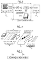
- Figure 1 appended to this description schematically illustrates the complete compression chain and the different stages of the process which has just been recalled.
- the length of the vectors, the choice and the size of the dictionary determine the final compression rate of the image and thereby the degradations made to it.
- Decompression is an easier operation to perform and allows a fast simplified algorithm.
- vector quantization proper various methods and quantifiers implementing these methods are known. Some types of vector quantizers will be briefly discussed below.
- a first type of quantifier according to known art was developed by "Brigham Young University” and manufactured by the company DARPA MOSIS in the form of a large-scale integrated circuit ("VLSI").
- the algorithm used is of the "MRRVQ” type ("Mean Residual Reflected Vector Quantizer", that is to say based on the difference of least squares of a reflected vector). This realization is described in the article by Brent E. NELSON and Christopher J. READ: “A Bit Serial VLSI Vector Quantizer", published in IEEE of April 1986.
- this type of structure is much too slow when it comes to performing processing in real time, such as compression of digital images. Furthermore, in this case, the dimensions of the silicon surface required are also much too large.
- a second type of vector quantizer uses a so-called “systolic" architecture, that is to say made up of macro-elements repeated a determined number of times and which are connected to each other.
- the algorithm used in the device described calls for the calculation of the Euclidean Distance.
- This architecture has several advantages: configuration and repetitive cells, continuous quantification and simple control logic.
- Vector quantizers of this type are produced in the form of components (integrated circuits) in CMOS technology and are commercially available under the brand MICRO DEVICES. More precisely, there are two configurations, distributed under the references MD 12210 Fuzzy Set Comparator and MD 1212 Fuzzy Data Correlator.
- the first component notably implements a neural network and calculates the HAMMING distance between two vectors, in bit-by-bit mode, or calculates the absolute distance, as soon as the components of the vectors have a size greater than one bit.
- this component is not intended for real-time image compression application. Even if it were possible to significantly increase its operating frequency, the processing time being directly proportional to the number and size of the vectors, we would quickly reach the maximum of its possibilities.
- the architecture of this component is therefore not suited to the types of preferential applications targeted by the invention.
- the second component is a correlator which calculates the HAMMING distance between a vector of maximum length of 128 bits and a frame of the same depth stored in the component at the start of each correlation.
- This component is intended for the comparison of various types of digital signals: fields of Radar and Sonar, synchronization, recognition and comparison of images.
- the invention proposes to overcome the drawbacks of the devices of the known art, some of which have just been recalled. Its main aim is a method authorizing real-time compression of digital images, as well as a vector quantizer device implementing the method.
- the invention proposes a bit serial architecture. This is composed of a set of macro elements, which associated with each other, allow to calculate the difference between two vectors.
- the first vector is called the input vector and the second is contained in a dictionary.
- the algorithm used uses the calculation of the absolute distance ⁇
- for k 1 to k max with k dimension of the vector.
- the invention also relates to a vector quantizer device for implementing this method.
- Vector quantization will be implemented for a digital image compression process comprising the phases Ph1 to Ph3 previously described and illustrated in Figure 1: cutting a black and white image of 256 ⁇ 256 ⁇ 8 bits into square blocks of 8 ⁇ 8x8 bits (or 8 ⁇ 8 pixels) and transformation into Discrete Cosine Transform TCD of these blocks, vector quantization into vectors of dimensions 3 or 5, coded using a DICO dictionary of 16, 64 or 256 vectors, and HUFFMANN encoding of the binary information thus obtained.
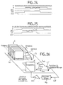
- the principle of vector compression is illustrated more particularly by FIG. 2.
- the vectors to be coded X i or input vectors, are presented to the vector quantizer QV which compares them to a series of vectors W i contained in a DICO dictionary.
- the development of this DICO dictionary is carried out according to methods also common to the known art, for example by implementing the Linde-Buzo-Gray algorithm already mentioned.
- the number of these vectors W i is naturally less important than the possible number of vector X i so that there can be compression.
- the dimension k of the vectors W i is the same as that of the vectors X i .
- the DICO dictionary includes 16, 64 or 256 vectors.
- for k 1 to k max .
- the QV quantizer performs the following function: comparison of a vector X i of 3 or 5 signed bytes, to one or more waves of 16 simultaneous vectors W i .
- the quantizer QV generates an index or address AD Wi of the vector W i of the closest dictionary, in the sense of the distance d M , of the input vector X i to be quantified.
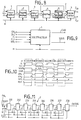
- this AD Wi address is coded on 8 bits, the four most significant bits representing the wave number No Va and the four least significant bits representing the vector number No Wi from the DICO dictionary.
- this AD Wi address is coded on 8 bits, the four most significant bits representing the wave number No Va and the four least significant bits representing the vector number No Wi from the DICO dictionary.
- the vectors to be quantified that is to say to code, X i are presented at the input of the quantizer QV in series form, coordinated by coordinate, starting from the most significant bit low or "LSB” according to English terminology (from “Low Significant Bit”), going through the most significant bit or “MSB” (from “Most Significant Bit”) and ending with the sign bit .
- This arrangement allows direct distance calculation, as will be explained later.
- This vector to be coded X i is presented to the vector quantizer simultaneously with a wave of a determined number of vectors W i from the DICO dictionary, for example four vectors according to an exemplary embodiment which will be detailed below.
- the quantizer QV After exhausting all the vectors W i of the DICO dictionary, the quantizer QV generates on its output a binary word AD Wi representing the address of the vector closest to the vector to be coded X i .
- FIG. 4 schematically illustrates the format of the vectors X i and W i .
- the vectors in the particular example illustrated by FIG. 4, can have the dimensions 3 (solid lines in the figure) or 5 (solid and hatched lines).
- the acronym S in the figure identifies the sign bit.
- the input data of the QV quantifier are the vectors X i , the output data are the addresses AD Wi .
- the DICO dictionary remains the same. Physically, in the usual way, the vectors W i of the DICO dictionary are recorded in an external memory.
- FIG. 5 illustrates, in a particular case, the progress of the stages of the search for the vector W i of the DICO dictionary closest to the vector to be coded X i , according to the method according to the invention.
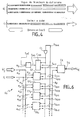
- FIG. 6, for its part, schematically illustrates an example of architecture of a vector quantizer device according to a preferred embodiment of the invention.
- the vector quantizer QV is of the modular type, each elementary quantization module QV1 to QV n calculates, in particular, the absolute distance between the input vector X i and the vector of the dictionary W i for which it is responsible .
- step 1 we see that the most significant bit of the four distances associated with the vectors W1 , W2 , W3 and W4 are identical.
- the QV vector quantizer cannot therefore make a decision.
- step 2 we see that the bit of weight 1024 is zero except for the first distance.
- the vector quantizer QV eliminates the vector W1 .
- steps 3 to 7 the next 5 bits are all the same.
- the QV vector quantizer cannot make a decision.
- step 8 the bit of weight 32 is zero, except in the second distance.
- the vector quantizer QV eliminates the vector W3 .
- steps 9 to 12 the next 4 bits are all the same.
- the QV vector quantizer cannot make a decision.
- step 13 the bit of weight 2 is zero except in the second distance.
- the vector quantizer QV eliminates the vector W1 .
- step 14 we arrive at the last bit, which leads to the choice of the vector W2, it is this vector of the DICO dictionary which has the smallest binary distance with the input vector X i .
- the address AD Wi of this vector W i is calculated by an address calculation module CA. It is this address AD Wi which is transmitted, in the form of a binary word, to the output S Q of the vector quantizer QV.
- each of the vectors Wiy of each wave y (with y integer taking the values ⁇ 1,2,3,4 ⁇ ), is transmitted, via the input bus e W of the vector quantizer QV to one of the inputs belonging to a first series of inputs e11 to e n1 of the modules QV1 to QV n .
- the vector X i to be coded is transmitted, for its part, to each of the inputs of a second series of inputs e12 to e n2 of these same modules QV1 to QV n .
- Each module also has two separate outputs, S Q11 to S Qn1 and S Q12 to S Qn2 , respectively.
- the outputs of the first series are connected to a first output bus B sbn and the outputs of the second series are connected to a second output bus B F.
- each module raises a flag or "flag" according to the Anglo-Saxon terminology commonly used.
- This flag after a logical operation taking into account the distance of the module, is transmitted on the bus B snb .
- the vector quantizer proceeds by eliminating the elementary modules, according to the process which has been described in relation to FIG. 5.
- a particular module QV n which has found a smaller distance than the other modules will eliminate them. These modules will lower their flags.
- the last flag which remains raised designates the module which has found the vector Wiy of a nearest determined wave y, for example wave No 1.
- each of the elementary quantization modules QV1 to QV n notably includes a comparator.
- comparators receive the signal present on the output S e1 and generate the signals on the outputs SQ11 to SQ n1 and SQ12 to SQ n2 , respectively.
- a comparator C MD is also associated with the register M D. The latter receives as an input the signal present on the output S MD of the register M D and on the output Sel, and generates output signals on two outputs S M1 and S M2 , connected respectively to the buses B sbn and B F.
- the elimination process also concerns the register M D. It is treated exactly as an elementary quantification module. It can therefore eliminate the other 16 elementary modules if it contains the shortest binary distance. It can also be eliminated if a vector of the DICO dictionary of the next wave is better than the previous ones. The new shortest distance is then recorded there.
- the remaining flags and the number of waves processed make it possible to find the address in the DICO dictionary of the vector W i closest to the input vector X i .
- This operation is carried out by the address calculator CA.
- This counts the number of vector waves W i , encodes the address of the nearest vector in a wave and records the address of the best vector of all the waves.
- the coding of the address can be carried out according to the configuration described in relation to FIG. 3.
- the address word AD Wi comprises a wave number No Va and a vector number No Wi , each being coded, in the illustrated example, on four bits.
- priority can be given, in encoding, to the first vector in a wave and to the first wave in the DICO dictionary.
- FIG. 7 is a timing diagram explaining the process for finding the minimum distance which has just been described.
- the signals F in are transmitted on the bus B F and the signals Z in on the bus B Sbn .
- the hatched parts of the signals in FIG. 7 show the elementary QV n quantization modules eliminated.
- the address calculator CA can generate the appropriate address word AD Wi on the output S Q.
- FIG. 8 schematically represents a possible embodiment of an elementary quantizer module QV n .
- Each of these modules QV n receives on a first input the input vector X i to be coded and one of the vectors W in of the DICO dictionary associated with this module No n, for example one of the 16 vectors of this dictionary, if there is only one wave of vectors W i , or one of the 16 vectors of one of the four successive waves, in the example described.
- Each module comprises, arranged in cascade, a subtractor 1, a shift register 2, an absolute value calculator 3, an adder 4, a bidirectional shift register 5 and a comparator 6, the two outputs of which generate the respective signals Z i and F i already described, and also named SQ i1 and SQ i2 , respectively.
- the logic is of the sequential type, synchronized with the bit times: the input vectors X i and the vectors of the dictionary are presented in serial form. Also a clock signal H is distributed to all circuits 1 to 6.
- the QV n modules have a structure of the "pipeline" type, with a continuous flow of data.
- the shift register 2 has a depth of 8 bits and the bidirectional shift register 5 has a depth of 12 bits.
- a large number of dedicated links are provided between the circuits. For reasons of simplicity, only the essentials necessary for the proper understanding of the invention have been shown.
- each elementary quantization module QV n supports the comparison between the input vector X i to be coded and one of the vectors W i of the DICO dictionary.
- the circuits 1 to 6 successively carry out the following operations: difference, in 1, between the coordinates of the vectors X i and W i ; calculation of the absolute value, in 3, of these differences and sum, in 4, of these absolute values.
- the coordinates are coded, in the example described, on 8 signed bits (-128 to +127), presented in series at the input of subtractor 1 ("LSB" first and “MSB” and sign last).
- the 8-bit shift register 2 makes it possible to wait for the sign bit and then calculate the absolute value of the result, on 8 unsigned bits (0 to +255).
- the adder 4 is looped back on itself by the 12-bit shift register 5. allowing to store the sum of the absolute values ("LSB" first.
- the 12 bits (0 to +4095) allow to work with vectors of a maximum of 16 coordinates. the final result is the distance between the vectors on 12 bits (“LSB" first).
- the comparator 6 compares the distances between the 16 elementary quantizer modules QV n according to the steps described in relation to FIG. 5.
- the two outputs of the comparator 6 generate, on the one hand, the flag signal F in and, d ' on the other hand, the signal Z i .
- the latter represents a zero bit detection signal.
- the flag signal F in is used to designate the elementary quantizer module QV n having found the minimum distance, as the timing diagram of FIG. 6 illustrated.
- the signal Z indicates that other elementary modules have a zero bit in their distance, which will trigger the possible elimination of the module QV n and the lowering of the flag F in .
- the comparison also relates to the register M D containing the smallest distance from the preceding waves, when several successive waves are processed, according to the preferred embodiment of the invention.
- this register M D comprises circuits provided with a comparator, quite similar to the elementary quantizer modules QV n . It therefore also generates a flag signal (output S M2 ) and a signal Z i (output S M1 ).
- the continuous flow of data through the QV modules n means that the slowest operation rate must be respected, in this case that of the 12-bit addition which requires twelve clock periods. It follows that, in the example described, the coordinates of the vectors being composed of 8 bits, these must be separated by 4 non-significant bits.
- the final comparison also requires a specified time interval.
- the nearest vector address is only available 30 clock periods after the last bit of the last vector coordinate of the last wave.
- each elementary quantizer QV n and the circuits of the register M D as well as its associated elements C MD can be produced by any appropriate technology, within the reach of those skilled in the art.
- the subtractor 1 is shown diagrammatically in FIG. 9.
- the subtractor receives the clock signal H, clocked on the bit time.
- FIG. 10 is a timing diagram illustrating the operation of the subtractor 1.
- the signals have the same references as in FIG. 9.
- four successive subtractions of 8 signed bits were produced, corresponding to four waves of vectors W i from the DICO dictionary.
- FIG. 11 illustrates an example of shift register 2 which can be used in the context of the invention.
- the shift register 2 in a conventional manner, comprises eight flip-flops D, 201 to 208, arranged in cascade.
- the register 2 receives, on a first input of the first flip-flop 201, the signal SUB, result of the subtraction and generated by the subtractor 1.
- the signal RST is asynchronous and resets the content of the register to zero. It has been previously described. It is transmitted to all the scales (reset input).
- a signal EN3 validates the propagation of the data along the register 2. It must be in the logic "1" state before the shift process, in the example with the type of logic chosen. It is also transmitted on a second input of all the flip-flops. Finally, the clock signal H is transmitted to the inputs provided for this purpose of all the flip-flops.
- the last flip-flop 208 delivers an OUTRG signal.
- This denier is equal to the signal SUB after an offset of eight clock periods.
- the timing diagram in Figure 12 illustrates this process.
- the signals represented on this timing diagram have the same references as those in FIG. 11.
- FIG. 13 illustrates an example of circuit 3 calculating absolute value usable in the context of the invention.
- the output of the AND logic circuit 31 is connected to the input of the OR logic circuit 32, the "true" output of the flip-flop 33 is looped back to the non-inverting input of the AND gate 31 and, moreover , is connected to the second output of the OU-EXCLUSIVE door 34, the inverted output of the latter is connected to the second input of door 35, the outputs of doors 35 and 36 are each connected to one of the two inputs of an OR gate 37 and the output thereof is connected to the second input of the AND gate 38, output stage of circuit 3.
- FIG. 14 illustrates three examples of calculation of the absolute value of OUTRG input signals.
- the signals represented on this flowchart have the same references as in FIG. 13.
- the adder 4 shown in more detail in FIG. 15, is of a conventional type. It comprises combinational logic circuits 40, generating a sum signal SOM and a retained signal CO, and a register for recording the retention constituted by a flip-flop 41.
- the signals to be added are, on the one hand, the signal ABS coming from the circuit 3 for calculating the absolute value and the signal ORB1, output signal from the bidirectional shift register 5 which will be described in the following. This signal is equal to the previously calculated result. At the very beginning of the calculations, all the bits of this signal are naturally equal to zero.
- the carry register 41 receives, on a reset input a signal RST1, which resets the flip-flop to zero before starting the calculation of the sum, the clock signal H on the clock input of the flip-flop and a signal EN5 for validation of propagation of the carry.
- the "true" output signal from flip-flop 41 is looped back to the inputs of the circuits for calculating the sum SOM and the reserve CO.
- the result of the addition is provided without delay, to the nearest propagation time. Normally, the CO carry signal is not used outside circuits 3.
- the timing diagram in Figure 16 is an example of five specific additions.
- the signals represented on this timing diagram have the same references as in FIG. 15.
- the adder works on 12 bits since it receives the output of the bidirectional shift register 5.
- the addition process is as follows:
- the bidirectional shift register 5 has a double role: on the one hand it accumulates the sum of the distances by a loopback on the adder, as previously described, on the other hand, it allows the output of the result, in reverse order to allow comparison.
- the shift register 5 comprises 12 flip-flops 501 to 512 in cascade, linked together using a network of logic gates allowing forward or reverse propagation of the bits of the input signal, depending on the logic state of a particular control signal.
- the input signal is the SOM signal generated by the adder 4.
- the bidirectional shift register also receives a reset signal RST2 of all the flip-flops 501 to 512, the clock signal H, a validation signal EN6 of propagation of the data bits and a direction control signal SENS , determining the direction of propagation.
- this signal is at logic "1" for the direction of data accumulation and at logic "0" for output in reverse of data.
- the output signal ORB1 corresponds to the forward movement of the data, with a delay of 12 bits (clock periods) and is retransmitted to one of the inputs of the adder 4, as it was previously described.
- the signal OUT2 corresponds to the reverse output of the data, starting from the most significant bit ("MSB"). This signal is transmitted to comparator 6, as described below.
- FIG. 18 is a timing diagram illustrating the progress of the signals in the bidirectional shift register 5.
- the signals illustrated by this timing diagram have the same references as in FIG. 17.
- the sequence represented by the signal SOM ie 110010010000 (simple hatching on the timing diagram) is found on the signal ORB1 shifted by twelve clock periods H. It is retransmitted to the adder 4.
- the following sequence of the signal SOM is 110010110000. Intended for the comparator, it is retransmitted by the signal OUT2 in reverse, ie 000011010011 (double hatching on the timing diagram), because the SENS signal has changed to logic "0".
- Comparator 6 also has a dual role. The first is to manage a flag which is used to indicate that it has detected the shortest distance. The second role is to detect null bits in the distance it processes. During the comparison process, this information is transmitted to all the comparators to eliminate them if necessary.
- FIG. 19 illustrates an example of an elementary comparator architecture 6 which can be implemented in the context of the invention.
- the output carrying the signal F i is looped back, on the one hand, to the non-inverting input of the AND logic gate 61, and on the other hand, to a first input of an AND gate 62, the output of the NAND logic gate 60 is connected to the second input of the AND logic gate 62 and the output of the latter is connected to the second input of the OR logic gate 63.
- the comparison process takes place according to the steps described in relation to FIG. 5.
- the elementary quantization modules QV n are synchronized with one another during this process.
- the distances are compared to each other bit by bit, starting with the most significant bit ("MSB").
- the flag F i is raised ("1" logic), this by using the signal SET3.
- the elementary quantization module QV n concerned remains in the race in the search for the smallest distance. It switches to logical "0" if one of the comparators 6 of the other modules sees a smaller distance.
- FIG. 20 schematically represents all of the comparators of the vector quantizer QV and illustrates the process of progressive elimination of these.
- the comparators in dotted lines are eliminated, the corresponding flag F i is at logic "0", as well as the signal Z i .
- the distance 000011001000 conveyed by the signal OUT2 was smaller than the other distances. It follows that the flag F i remained at logic "1" throughout the comparison process. Z i has the value 111100110111, which is the logical inverse of the distance conveyed by the input signal OUT2.
- the signal ORG is transmitted to the circuit C MD (FIG. 6) which includes, like the elementary quantizers QV n , a comparator. This circuit will be detailed in the following. This signal is offset by 12 clock periods with respect to the input signal Z.
- the timing diagram of FIG. 24 illustrates, for a particular example, the process of memorizing a distance conveyed by the signal Z and represented by the sequence 111100110111.
- the storage is carried out under the control of the validation signal EN.
- the register M D was reset to zero by the signal RST.
- the flow diagram of FIG. 25 illustrates the process of output (signal ORG) of this same sequence outside the register M D , always under the control of the validation signal EN.
- FIG. 26 illustrates the complete comparison circuits, including the circuit for comparing the circuits C MD (FIG. 6): comparator 6 '.
- the inverse of the minimum distance is stored after each wave in the shift register M D of 12-bit depth.
- the logic gate CL performs a first logic OR of all the signals Z i generated by the elementary comparators 6.
- a second gate logic CL ' performs a logic OR of the output signal from gate CL and of signal Z min , generated by comparator 6'. This signal is in every respect similar to the signals Z i . Only one OR gate could be used.
- the resulting flag, referenced Z INVD is treated differently from the other 16. If it is lowered, it means that a vector is closer in the wave that has just been processed. This signal therefore commands the storage of a new address of the best vector of the DICO dictionary.
- the purpose of encoding the input vectors is to reduce the information provided by all the flags being quantified to a simple and final datum: the address, in the DICO dictionary, of the vector W i closest to the vector to be quantified X i .
- each of the 16 elementary QV n quantization modules produces a flag indicating the passage of a relevant vector from the DICO dictionary.
- a seventeenth flag concerns the memory of the shortest distance found. This last flag indicates that nothing better has been found in the wave just passed. It is this which causes the memorization of the address of a new vector. It is therefore at this level that the priority given to one vector or another is decided if they are at the same binary distance from the vector to be quantified.
- priority is given to the lowest index in a given vector wave and to the first of several. It follows that one uses, in a preferred embodiment of the invention, a priority encoder and a wave counter.
- FIG. 27 illustrates an exemplary embodiment of the address calculator CA (FIG. 6). It includes a priority 70 encoder receiving the 16 flags F1 to F16 to be encoded. These flags are generated by the elementary comparators 6.
- This encoder 70 can be produced, in a conventional manner, in combinatorial logic. In the example described, it codes the 16 flags F i in a binary word of four bits. These four bits represent the vector number in a No Wi wave ( Figure 2).
- a signal VAL is derived from the flag signals F i indicating that at least one flag is in the logic state "1".
- the four bits No Wi are transmitted to four flip-flops, 751 to 754, of the "latch" type of an address memory register 75, which includes four others, 755 to 758.
- a second important circuit of the address calculator CA consists of a counter 74 whose purpose is to count the number of waves. As output, it generates a binary number No va , also of four bits, representing the wave number, and transmitted to the last four flip-flops, 755 to 758, to be recorded there.
- An OR gate 72 combines the signal VAL generated by the encoder 70 and the signal Z INVD produced by the comparator 6 '(FIG. 26).
- the output of this logic gate 72 is transmitted to a first input of a flip-flop 73.
- the signal Z INVD and a validation control signal ENA_AD are transmitted, respectively to the inverting and non-inverting inputs, of an AND logic gate 71.
- the output of this logic gate is transmitted to the validation input of the flip-flop 73 and of all the flip-flops of register 75. It causes the writing of the address in the flip-flops of register 75 and the writing of the output signal of logic gate 72, combination of signal VAL and signal Z INVD , that is to say the logical OR of all the flags.
- the signal AD_HERE at the output of flip-flop 73, indicates that a close vector has been found.
- the signal ENA_CPT is used to increment the counter 74 at each passage of the wave of vectors. It must be set to logical "1" for a clock period after each wave.
- all flip-flops, 73 and 751 to 758, as well as the counter 74, receive the clock signal H and a reset signal RST_AD.
- the binary signals on the outputs of flip-flops 751 to 758 are the address bits AD1 to AD8 of the address vector AD Wi associated with the best vector W i of the DICO dictionary.
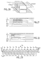
- FIG. 28 is a timing diagram illustrating, on a particular example, the address encoding during the first wave of vectors, using the circuits CA which have just been detailed.
- Figure 29 is a timing diagram illustrating address encoding during a second wave.
- a vector more efficient than the previous vectors had passed through F19.
- the result is 18 (in hexadecimal), i.e. vector 8 of the second wave or coded wave 1.
- the wave counter 74 accepts a maximum of 16 successive waves. It is clear that the invention cannot be limited to this particular value. You can easily increase the capacity of this meter. Naturally, the number of address bits must be increased concurrently with the increase in the capacity of the counter.
- the speed characteristics of a quantizer according to the invention can be further improved.
- the speed of the QV quantifier is physically limited.
- the design also influences the overall characteristics: the specification of critical paths makes it possible to predict and improve the operating speed to a large extent. The fact remains that when all the parameters have been optimized, it is no longer possible to increase the operating speed.
- the speed of quantification can be further increased by splitting the DICO dictionary into N distinct parts, or sub-dictionaries. Each sub-dictionary is associated with a particular quantifier. If the number of vectors W i in the DICO dictionary is divisible by N, it follows that the gain in speed obtained is practically N times that achieved when using a single quantizer, with the same total amount of vectors W i naturally . Each input vector X i is presented simultaneously to the N quantifiers. The control signals remain the same as those previously described and are identical for each quantizer. The difficulty is to find the minimum distance among the N quantifiers, and therefore the most relevant vector in the dictionary, for the current wave.
- the first is based on the fact that the signal Z out , as has been shown, is the logical inverse of the minimum distance. This information can be used to compare the different quantifiers with each other. In the same way that the elementary modules are eliminated inside a quantifier, one will be able to eliminate the quantizers put in parallel.
- Figure 30 illustrates the paralleling of two quantizers. Naturally, this number was chosen only so as not to unnecessarily overload the diagram. A larger number of parallel connections is perfectly achievable.
- the control signals have been grouped together under the general reference S com and are distributed in the same way to the two vector quantizers QV A and QV B.
- the output signals Z outA and Z outB are inverted by the inverting logic gates, INV A and INV B , respectively.
- the comparator modules COMP A and COMP B associated with the vector quantizers QV A and QV B , produce signals Z A and Z B , as well as two flags F A and F B. These comparator modules play the role of the comparator module 6 ′ in FIG. 26.
- the signals Z A and Z B can be used , by combining them using a logic gate OR CL AB into a single signal Z, to eliminate either of the quantizers QV A or QV B , depending on whether the best performing vector is "seen" by the first or the second vector quantizer.
- This process can naturally be extended to N vector quantifiers, with N> 2.
- Each of the vector quantizers QV A and QV B generates its own address word, AD Wi A and AD Wi B respectively. One or the other of these addresses is used according to the flag F A or F B remaining, thereby indicating which is the best vector of the DICO dictionary to take into account for the current wave.
- the logic implemented at the level of the global system is very similar to that implemented in each vector quantizer. It consists, at this last level, in using 16 + 1 comparator modules joined by a logical OR. We can do this with the (N ⁇ 16 + 1) distances. To do this, it suffices to make a slight modification to the configuration of the circuits: the zero detection signal Z out is opened to all of the quantifiers. To do this, if we refer again to Figure 26, it suffices physically cutting the connection between the output of the logic gate CL 'and the input of the register M D , in other words, this signal is no longer directly looped back onto the comparator 6'.
- the signals Z outA and Z outB are combined into a logical OR by the gate CL ' AB and are looped back, in the form of signals representing the inverse of the minimum distance: Z inA or Z inB , to the comparators of the two vector quantizers QV A and QV B , or more generally towards the N quantizers in parallel.
- Another solution dual from the previous ones, is to quantify several input vectors X i simultaneously, using a single DICO dictionary. To do this, several vector quantizers are also used in parallel.
- FIG. 32 illustrates an example of such an embodiment, reduced to two vectors to be quantified presented simultaneously. Elements identical or similar to those of FIGS. 30 or 31 bear the same references and will not be described again.
- the same 16 vectors (in the example described) from the DICO dictionary (not shown) are presented simultaneously to the two vector quantizers QV A and QV B.
- two different vectors to be quantified, referenced X i A and X i B are presented at the input.
- Each quantizer, QV A or QV B generates as before the signals Z outA and Z outB , on the one hand, and the address signals, AD Wi A and AD Wi B.
- These two series of signals are associated with the respective vectors X i A and X i B. These signals are processed in the manner previously described.
- N quantizers to process N different vectors to quantize makes it possible, on the one hand, to multiply practically by N the overall speed of quantification and, on the other hand, allows a significant simplification of the wiring since the control signals are common to all vector quantizers.
- the same dictionary is used by these N vector quantizers.
- the N vectors X i N are necessary to be quantified simultaneously.
- the vectors presented simultaneously must have the same dimension.
- the vectors to be quantified are likely to have random dimensions (number of coordinates), typically 3 or 5 coordinates as illustrated in FIG. therefore cannot use this embodiment for this particular type of application.
- serial data flow via certain intermediate registers allows the simultaneous execution of several operations, according to a mode known as the acronym “pipe-line”. For example, a subtraction can start before the addition of the result of the previous subtraction is completed.
- the bidirectional register 5 (of 12 bits in the example described) constitutes a "bottleneck".
- the use of two alternating registers would make it possible to gain 13 clock periods between two successive waves of vectors, this naturally at the cost of a slight increase in the complexity of the control logic.
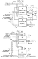
- the vector quantizer as described above can be inserted into a set of computerized circuits which supply it with the control signals necessary for its proper functioning, store the vectors of the dictionary, supply them and, finally, generate the vectors to be quantified in serial format.
- circuits 8 in FIG. 33 The architecture of such a system is illustrated diagrammatically by the circuits 8 in FIG. 33.
- circuits 8 are controlled by a microprocessor 80 which also generates the vectors to be quantified. It is, for example, this microprocessor which will control the preliminary stages of calculation of TCD (FIG. 2).
- the vectors to be quantified must be presented in serial format as indicated. To do this, a parallel-series converter 85 is used in particular which transmits the vectors to quantify X i to the vector quantizer QV.
- the control signals are generated by a read-only memory of the "ROM" type ("Read Only Memory”) 81.
- the necessary memory capacity naturally depends on the number of states to be generated. It depends in particular on the size of the vectors and that of the vectors in the dictionary (number of waves to be processed).
- a counter 82 conventionally generates the read addresses of memory 81.
- the vectors of the dictionary are physically stored in a random access random access memory 83 or "RAM" according to the usual English terminology.
- the dictionary is loaded before the quantification operations start.
- a counter 84 generates the read addresses of the memory 83.
- the storage format is particular. 16 bits are required for each coordinate of each wave of 16 vectors (in the example illustrated). We therefore need 16-bit words, the first of which is the bit of lowest weight (“LSB") of the first of the coordinates of the first 16 vectors. The last is formed by the 16 sign bits of the last coordinate of the last 16 vectors of the dictionary.
- a simple PORT 86 is used to retrieve the AD Wi address at the end of quantification. This is transmitted, for example to the microprocessor 80 for further processing according to the known art.
- FIG. 33 Only the elements essential for a good understanding of the invention have been shown in FIG. 33. A certain number of conventional signals are necessary: clock and reset signals for example. A control signal to start the quantification process and a signal indicating the availability of a result are also required.
- the invention is not limited to the sole examples of embodiments precisely described in relation in particular to FIGS. 3 to 33.
- Many types of circuits in particular integrated circuits configurable on demand, can be implemented to fulfill the essential functions of the vector quantizer according to the invention.
Abstract
Description
La présente invention concerne un procédé de quantification vectorielle d'un signal numérique, notamment pour une application dans le domaine de la compression des images numériques.The present invention relates to a vector quantization method of a digital signal, in particular for an application in the field of compression of digital images.
De façon encore plus précise, la présente invention trouve une application avantageuse dans le domaine de la compression, en temps réel, d'images numériques mobiles.Even more precisely, the present invention finds an advantageous application in the field of real-time compression of mobile digital images.
L'invention concerne également un dispositif pour la mise en oeuvre d'un tel procédé.The invention also relates to a device for implementing such a method.
La compression d'images est devenue un élément clé pour la transmission de signaux numériques. On connaît deux types principaux de techniques de compression d'images, techniques qui peuvent éventuellement s'associer :
- les premières techniques utilisent la corrélation spatiale (quantification scalaire, quantification vectorielle, transformées diverses telles que : Transformée Cosinus Discrète ou T.C.D., Ondelettes, etc..); et
- les techniques d'estimation et/ou de compensations qui utilisent les redondances temporelles.
- the first techniques use spatial correlation (scalar quantification, vector quantization, various transforms such as: Discrete Cosine Transform or TCD, Wavelets, etc.); and
- estimation and / or compensation techniques which use temporal redundancies.
Ces techniques offrent des taux de compression différents. Leur utilisation est déterminée par diverses considérations techniques et financières : taux de compression à atteindre, complexité de mise en oeuvre, coût, etc..These techniques offer different compression rates. Their use is determined by various technical and financial considerations: compression ratio to be achieved, complexity of implementation, cost, etc.
La présente invention s'intéresse plus particulièrement aux techniques de compression d'images numériques mettant en oeuvre la quantification vectorielle. Il a été démontré, en effet, que la quantification vectorielle était plus performante que la quantification scalaire.The present invention relates more particularly to digital image compression techniques implementing vector quantization. It has been shown, in fact, that vector quantization is more efficient than scalar quantization.
La technique de Quantification Vectorielle repose sur la théorie de l'information de SHANNON concernant le débit et la distorsion. D'après cette théorie fondamentale, la compression est plus élevée en travaillant sur des vecteurs que sur des scalaires, et son efficacité est proportionnelle à la dimension de ces vecteurs.The Vector Quantization technique is based on SHANNON's information theory concerning bit rate and distortion. According to this fundamental theory, the compression is higher when working on vectors than on scalars, and its efficiency is proportional to the size of these vectors.
De plus, il apparaît que l'encodage de source est optimisé lorsqu'on travaille sur des blocs de taille déterminée x×y.In addition, it appears that the source encoding is optimized when working on blocks of determined size x × y.
La Quantification Vectorielle est un procédé de codage. De façon succincte, il consiste à décrire un signal à coder en un nombre déterminé de vecteurs. De façon remarquable, certaines formes de vecteurs apparaissent très souvent, d'autres formes sont plus rares, voire inexistantes.Vector Quantization is a coding process. Briefly, it consists in describing a signal to be coded in a determined number of vectors. Remarkably, certain forms of vectors appear very often, other forms are rarer, even non-existent.
A partir de cette constatation, on constitue un dictionnaire contenant les vecteurs les plus fréquents et on y recherche le vecteur le plus proche du vecteur à coder. Ce dictionnaire étant commun à un organe émetteur et à un organe récepteur, il suffit alors de transmettre l'indice ou adresse du vecteur du dictionnaire.From this observation, a dictionary containing the most frequent vectors is created and the vector closest to the vector to be coded is sought. This dictionary being common to an emitting member and to a receiving member, it is then sufficient to transmit the index or address of the vector of the dictionary.
Les performances de ce procédé de codage dépendent de la formation des vecteurs, de la pertinence du dictionnaire choisi (longueur et méthode de génération) et de la mesure choisie pour comparer deux vecteurs.The performance of this coding process depends on the formation of the vectors, the relevance of the dictionary chosen (length and generation method) and the measurement chosen to compare two vectors.
De façon avantageuse, dans le cadre de l'invention, on utilisera préférentiellement des vecteurs de 2 à 16 octets signés, issus de la transformation en Cosinus Discret T.C.D. de blocs d'images de 8×8 bits.Advantageously, in the context of the invention, use will preferably be made of vectors of 2 to 16 signed bytes, resulting from the transformation into Discrete T.C.D. 8 × 8 bit image blocks.
On compare ensuite chaque vecteur à ceux d'un dictionnaire comprenant 16, 64 ou 256 vecteurs (ou plus). La génération du dictionnaire proprement dite est basée sur des propriétés statistiques de l'image. Diverses méthodes sont connues. On peut, par exemple utiliser l'algorithme dit "LBG" (Linde-Buzo-Gray).Each vector is then compared to those of a dictionary comprising 16, 64 or 256 vectors (or more). The actual dictionary generation is based on statistical properties of the image. Various methods are known. One can, for example use the algorithm called "LBG" (Linde-Buzo-Gray).
Pour comparer les vecteurs à coder et les vecteurs du dictionnaire, on utilise la notion de distance. Pour ce faire, différents algorithmes sont connus et sont rappelés ci-après. On peut calculer, notamment :
- la Distance Euclidienne, soit

W = vecteur du dictionnaire (indépendant du type de distance choisie) et k dimension commune aux vecteurs; - la Distance Absolue, soit

- la Distance Pondérée, soit

- la Distance Supérieure, soit

- the Euclidean Distance,
W = vector of the dictionary (independent of the type of distance chosen) and k dimension common to the vectors; - the Absolute Distance,
- the Weighted Distance,
- the Upper Distance, i.e.
L'expérience montre que le type de distance choisi influe peu sur le résultat, aussi dans le cadre de l'invention on utilisera de façon préférentielle, pour des raisons de simplicité, la distance absolue.Experience shows that the type of distance chosen has little effect on the result, so in the context of the invention, absolute distance will preferably be used, for reasons of simplicity.
Dans ce qui suit, pour fixer les idées, on admettra , sans que cela soit limitatif en quoi que ce soit de la portée de l'invention, que la chaîne complète de compression d'une image numérique comprend les trois phases suivantes :
- Ph₁ : découpage d'une image en noir et blanc de 256×256×8 bits en blocs carrés de 8×8 bits et transformation en Transformée Cosinus Discrète T.C.D. de ces blocs;
- Ph₂ : quantification vectorielle en vecteurs de
dimensions 3 ou 5, codés à l'aide d'un dictionnaire DICO de 16, 64 ou 256 vecteurs; et - Ph₃ : encodage de HUFFMANN des informations binaires ainsi obtenues.
- Ph₁: cutting of a black and white image of 256 × 256 × 8 bits into square blocks of 8 × 8 bits and transformation into Discrete Cosine Transform TCD of these blocks;
- Ph₂: vector quantification in vectors of
dimensions - Ph₃: HUFFMANN encoding of the binary information thus obtained.
La figure 1 annexée à la présente description illustre de façon schématique la chaîne complète de compression et les différentes étapes du procédé qui vient d'être rappelé.Figure 1 appended to this description schematically illustrates the complete compression chain and the different stages of the process which has just been recalled.
La longueur des vecteurs, le choix et la taille du dictionnaire déterminent le taux final de compression de l'image et par là même les dégradations apportées à celle-ci.The length of the vectors, the choice and the size of the dictionary determine the final compression rate of the image and thereby the degradations made to it.
A la décompression, les opérations inverses sont effectuées. La décompression est une opération plus aisée à réaliser et autorise un algorithme simplifié rapide.On decompression, the reverse operations are carried out. Decompression is an easier operation to perform and allows a fast simplified algorithm.
Le procédé de codage rappelé a été divulgué, par exemple, dans la Thèse de l'Université de Metz de Jamal BAINA intitulée "Codage Hybride Adaptatif d'Images en Vue de la Transmission Bas Débit : logiciel et matériel", janvier 92.The recalled coding process was disclosed, for example, in the Thesis of the University of Metz by Jamal BAINA entitled "Adaptive Hybrid Coding of Images for Low Speed Transmission: Software and Hardware", January 92.
En ce qui concerne plus particulièrement la quantification vectorielle proprement dite, divers procédés et quantificateurs mettant en oeuvre ces procédés sont connus. Quelques types de quantificateurs vectoriels vont être brièvement évoqués ci-après.With regard more particularly to vector quantization proper, various methods and quantifiers implementing these methods are known. Some types of vector quantizers will be briefly discussed below.
Un premier type de quantificateur selon l'art connu a été développé par la "Brigham Young University" et fabriqué par la société DARPA MOSIS sous la forme d'un circuit intégré à grande échelle ("VLSI"). L'algorithme utilisé est du type "MRRVQ" ("Mean Residual Reflected Vector Quantizer", c'est-à-dire basé sur la différence des moindres carrés d'un vecteur réfléchi). Cette réalisation est décrite dans l'article de Brent E. NELSON et Christopher J. READ : " A Bit Serial VLSI Vector Quantizer", paru dans IEEE d'avril 1986.A first type of quantifier according to known art was developed by "Brigham Young University" and manufactured by the company DARPA MOSIS in the form of a large-scale integrated circuit ("VLSI"). The algorithm used is of the "MRRVQ" type ("Mean Residual Reflected Vector Quantizer", that is to say based on the difference of least squares of a reflected vector). This realization is described in the article by Brent E. NELSON and Christopher J. READ: "A Bit Serial VLSI Vector Quantizer", published in IEEE of April 1986.
Bien qu'intéressant pour certaines applications, ce type de structure est beaucoup trop lent lorsqu'il s'agit d'effectuer un traitement en temps réel, tel que la compression d'images numériques. En outre, dans ce cas, les dimensions de la surface de silicium nécessaire sont aussi beaucoup trop importantes.Although interesting for certain applications, this type of structure is much too slow when it comes to performing processing in real time, such as compression of digital images. Furthermore, in this case, the dimensions of the silicon surface required are also much too large.
Un deuxième type de quantificateur vectoriel fait appel à une architecture dite "systolique", c'est-à-dire constituée de macro-éléments répétés un nombre déterminé de fois et qui sont reliés les uns aux autres.A second type of vector quantizer uses a so-called "systolic" architecture, that is to say made up of macro-elements repeated a determined number of times and which are connected to each other.
Un exemple de ce type d'architecture est décrit dans l'article de P. A. RAMAMOORTHY et al : "Bit-Serial VLSI Implementation of Vector Quantizer for Real-Time Image Coding", paru dans IEEE d'octobre 1989.An example of this type of architecture is described in the article by P. A. RAMAMOORTHY et al: "Bit-Serial VLSI Implementation of Vector Quantizer for Real-Time Image Coding", published in IEEE of October 1989.
L'algorithme utilisé dans le dispositif décrit fait appel au calcul de la Distance Euclidienne.The algorithm used in the device described calls for the calculation of the Euclidean Distance.
Cette architecture présente plusieurs avantages : configuration et cellules répétitives, quantification en continue et logique de commande simple.This architecture has several advantages: configuration and repetitive cells, continuous quantification and simple control logic.
Cependant, comme précédemment, elle est gourmande en surface de silicium et nécessite un grand nombre d'entrées/sorties.However, as before, it is greedy on the silicon surface and requires a large number of inputs / outputs.
En outre, elle est difficilement exploitable dans l'état actuel de la technique, en raison de l'important niveau d'intégration et du nombre de connexions externes qui lui sont nécessaires. Enfin l'inconvénient majeur provient de l'interconnexion des macro cellules qui fait croître le nombre de coup d'horloge proportionnellement aux nombre de vecteurs traités.In addition, it is difficult to use in the current state of the art, because of the high level of integration and the number of external connections which are necessary for it. Finally, the major drawback comes from the interconnection of macro cells which increases the number of clock strokes in proportion to the number of vectors processed.
Un troisième type de quantificateur vectoriel a été développé pour des applications de la logique floue. Des quantificateurs vectoriels de ce type sont réalisés sous forme de composants (circuits intégrés) en technologie CMOS et sont disponibles dans le commerce sous la marque MICRO DEVICES. De façon plus précise, il existe deux configurations, diffusées sous les références MD 12210 Fuzzy Set Comparator et MD 1212 Fuzzy Data Correlator.A third type of vector quantizer has been developed for applications of fuzzy logic. Vector quantizers of this type are produced in the form of components (integrated circuits) in CMOS technology and are commercially available under the brand MICRO DEVICES. More precisely, there are two configurations, distributed under the references MD 12210 Fuzzy Set Comparator and MD 1212 Fuzzy Data Correlator.
Le premier composant met notamment en oeuvre un réseau neuronal et calcule la distance de HAMMING entre deux vecteurs, en mode bit à bit, ou calcule la distance absolue, dès que les composantes des vecteurs ont une taille supérieure à un bit.The first component notably implements a neural network and calculates the HAMMING distance between two vectors, in bit-by-bit mode, or calculates the absolute distance, as soon as the components of the vectors have a size greater than one bit.
De nouveau, ce composant n'est pas destiné à l'application compression d'image en temps réel. Même s'il était possible d'augmenter significativement sa fréquence de fonctionnement, le temps de traitement étant directement proportionnel au nombre et à la dimension des vecteurs, on atteindrait rapidement le maximum de ses possibilités. L'architecture de ce composant n'est donc pas adaptée aux types d'applications préférentielles visées par l'invention.Again, this component is not intended for real-time image compression application. Even if it were possible to significantly increase its operating frequency, the processing time being directly proportional to the number and size of the vectors, we would quickly reach the maximum of its possibilities. The architecture of this component is therefore not suited to the types of preferential applications targeted by the invention.
Le second composant est un corrélateur qui calcule la distance de HAMMING entre un vecteur de longueur maximale de 128 bits et une trame de même profondeur mémorisée dans le composant au départ de chaque corrélation.The second component is a correlator which calculates the HAMMING distance between a vector of maximum length of 128 bits and a frame of the same depth stored in the component at the start of each correlation.
Ce composant est destiné à la comparaison de divers type de signaux numériques : domaines du Radar et du Sonar, de la synchronisation, reconnaissance et comparaison d'images.This component is intended for the comparison of various types of digital signals: fields of Radar and Sonar, synchronization, recognition and comparison of images.
Cependant son utilisation pour le codage d'image n'est pas possible car la distance de HAMMING n'est pas adaptée pour la compression d'images numériques.However, its use for image coding is not possible because the distance from HAMMING is not suitable for compressing digital images.
L'invention se propose de pallier les inconvénients des dispositifs de l'art connu, dont certains viennent d'être rappelés. Elle se fixe pour but principal un procédé autorisant la compression en temps réel d'images numériques, ainsi qu'un dispositif quantificateur vectoriel mettant en oeuvre le procédé.The invention proposes to overcome the drawbacks of the devices of the known art, some of which have just been recalled. Its main aim is a method authorizing real-time compression of digital images, as well as a vector quantizer device implementing the method.
Pour ce faire, l'invention propose une architecture bit série. Celle-ci est composée d'un ensemble de macro éléments, qui associés les uns aux autres, permettent de calculer la différence entre deux vecteurs. Le premier vecteur est dit vecteur d'entrée et le second est contenu dans un dictionnaire. De façon préférentielle, l'algorithme utilisé fait appel au calcul de la distance absolue Σ|X k - W k | pour k = 1 à k max avec k dimension du vecteur.To do this, the invention proposes a bit serial architecture. This is composed of a set of macro elements, which associated with each other, allow to calculate the difference between two vectors. The first vector is called the input vector and the second is contained in a dictionary. Preferably, the algorithm used uses the calculation of the absolute distance Σ | X k - W k | for k = 1 to k max with k dimension of the vector.
L'invention a donc pour objet un procédé de quantification vectorielle d'un signal numérique comprenant les étapes de conversion de ce signal en un vecteur à quantifier, au format série signé, de comparaison de ce vecteur à quantifier avec des vecteurs d'un dictionnaire de même dimension que le vecteur à quantifier, de détermination des distances binaires entre le vecteur à quantifier et les vecteurs du dictionnaire, de sélection de la distance minimale et de calcul de l'adresse du vecteur du dictionnaire correspondant à ce vecteur, caractérisé en ce que,
- I'étape de comparaison consiste à comparer, bits à bits, le vecteur à quantifier simultanément avec un nombre déterminé de vecteurs du dictionnaire;
- l'étape de détermination des distances consiste à générer simultanément des mots binaires représentant les distances entre le vecteur à quantifier et les vecteurs du dictionnaire; et
- l'étape de sélection de la distance minimale consiste à générer un signal de drapeau associé à chaque mot binaire et positionné à un premier état logique, à effectuer une séquence de comparaisons simultanées des bits desdits mots, en commençant par les bits de plus fort poids, à émettre pour chaque bit nul de chaque mot binaire un signal détectant cet état, à émettre un signal supplémentaire représentant le "OU" logique de tous ces signaux, à un premier état logique lorsqu'au moins un des bits des mots binaires est nul, à comparer les bits de chaque mot binaire à ce signal supplémentaire, à commuter lesdits signaux de drapeau des mots binaires, du premier état logique à l'état logique complémentaire, si le bit en cours de comparaison a la valeur "un" et si le signal supplémentaire est au premier état logique, et à éliminer les mots binaires associés à ces signaux de drapeau des comparaisons subséquentes, et à déterminer à partir des signaux de drapeau restés audit premier état l'adresse du vecteur du dictionnaire le plus proche du vecteur à quantifier.
- The comparison step consists in comparing, bit by bit, the vector to be quantified simultaneously with a determined number of vectors in the dictionary;
- the step of determining the distances consists in simultaneously generating binary words representing the distances between the vector to be quantified and the vectors of the dictionary; and
- the step of selecting the minimum distance consists in generating a flag signal associated with each binary word and positioned at a first logical state, in carrying out a sequence of simultaneous comparisons of the bits of said words, starting with the most significant bits , to transmit for each zero bit of each binary word a signal detecting this state, to send an additional signal representing the logical "OR" of all these signals, to a first logical state when at least one of the bits of the binary words is zero , compare the bits of each binary word to this additional signal, to switch said flag signals of the binary words, from the first logic state to the complementary logic state, if the bit being compared has the value "one" and if the additional signal is at the first logical state, and to eliminate the binary words associated with these flag signals from subsequent comparisons, and to determine from the flag signals remaining in said first state the address of the vector of the dictionary closest to the vector to be quantified.
L'invention a encore pour objet un dispositif quantificateur vectoriel pour la mise en oeuvre de ce procédé.The invention also relates to a vector quantizer device for implementing this method.
La structure du dispositif offre de nombreux avantages et parmi ceux-ci les avantages suivants :
- Le nombre de pads d'entrées/sorties est limité à une taille minimale;
- Les cellules sont toutes identiques et donc facilement reproductibles;
- Le résultat de la comparaison donne directement la distance minimale;
- Son architecture permet d'associer plusieurs quantificateurs vectoriels sans pour autant augmenter le temps de traitement;
- La taille du dictionnaire peut être variable avec le même quantificateur vectoriel. Il suffit d'effectuer une lecture par vague des vecteurs à quantifier. La contrepartie est que le temps de traitement est multiplié par le nombre de vagues.
- La logique de commande et de gestion nécessaire est très simple; et
- La dimension des vecteurs est aisément adaptable aux besoins.
- The number of input / output pads is limited to a minimum size;
- The cells are all identical and therefore easily reproducible;
- The result of the comparison gives the minimum distance directly;
- Its architecture makes it possible to associate several vector quantifiers without increasing the processing time;
- The size of the dictionary can be variable with the same vector quantizer. It suffices to perform a wave reading of the vectors to be quantified. The downside is that the processing time is multiplied by the number of waves.
- The control and management logic required is very simple; and
- The size of the vectors is easily adaptable to requirements.
L'invention sera mieux comprise et d'autres caractéristiques et avantages apparaîtront à la lecture de la description qui suit en référence aux figures annexées, et parmi lesquelles :
- La figure 1 illustre schématiquement une chaîne complète de compression d'images numériques intégrant une étape de quantification vectorielle;
- La figure 2 illustre schématiquement les étapes de la quantification vectorielle;
- La figure 3 illustre le codage de l'adresse d'un vecteur, selon un mode de réalisation préférée de l'invention;
- La figure 4 illustre schématiquement le format des vecteurs d'entrée à coder et des vecteurs du dictionnaire;
- La figure 5 illustre le déroulement des étapes de la recherche du vecteur du dictionnaire le plus proche du vecteur à coder;
- La figure 6 illustre schématiquement un exemple de quantificateur vectoriel selon un mode de réalisation préféré de l'invention;
- La figure 7 est un chronogramme explicitant le processus de recherche de distance minimale;
- La figure 8 représente de façon schématique un exemple de réalisation d'un module quantificateur élémentaire;
- la figure 9 illustre un exemple de soustracteur utilisé dans le module quantificateur élémentaire de la figure 8;
- La figure 10 est un chronogramme illustrant le fonctionnement de ce soustracteur;
- La figure 11 illustre un exemple de registre à décalage utilisé dans le module quantificateur élémentaire de la figure 8;
- La figure 12 est un chronogramme illustrant le fonctionnement de ce registre;
- La figure 13 illustre un exemple de
circuit 3 calculateur de valeur absolue utilisé dans le module quantificateur élémentaire de la figure 8; - Le chronogramme de la figure 14 illustre trois exemples de calcul de valeur absolue effectués par le calculateur de la figure 13;
- La figure 15 illustre un exemple d'additionneur utilisé dans le module quantificateur élémentaire de la figure 8;
- Le chronogramme de la figure 16 illustre cinq additions effectuées par l'additionneur de la figure 14;
- La figure 17 illustre un registre à décalage bidirectionnel utilisé dans le module quantificateur élémentaire de la figure 8;
- La figure 18 est un chronogramme illustrant la marche des signaux dans le registre à décalage bidirectionnel de la figure 17;
- La figure 19 illustre un exemple de comparateur élémentaire utilisé dans le module quantificateur élémentaire de la figure 8;
- La figure 20 représente schématiquement l'ensemble des comparateurs du quantificateur vectoriel de la figure 6;
- Les figures 21 et 22 illustrent deux exemples de comparaisons de distances effectuées par les comparateurs de la figure 20;
- La figure 23 illustre un exemple de mémoire utilisée pour le stockage de la plus courte distance trouvée dans les vagues précédentes;
- Les figures 24 et 25 sont deux chronogrammes explicitant la mémorisation et la sortie de ces distances dans et hors de la mémoire de la figure 23;
- La figure 26 illustre les circuits complets de comparaison d'un quantificateur vectoriel, incluant le circuit de comparaison des circuits de mémoire de la plus courte distance trouvée pendant les vagues précédentes;
- La figure 27 illustre un exemple de réalisation du calculateur d'adresse de la figure 6;
- La figure 28 et 29 sont deux chronogrammes illustrant l'encodage d'adresse lors d'une première et d'une seconde vague de vecteurs, à l'aide du calculateur d'adresse de la figure 27;
- Les figures 30 à 32 illustrent la mise en parallèle de plusieurs quantificateurs selon trois modes de réalisation;
- La figure 33 illustre schématiquement un exemple d'une architecture d'un système de compression d'image incluant un quantificateur vectoriel selon l'invention.
- FIG. 1 schematically illustrates a complete digital image compression chain integrating a vector quantization step;
- Figure 2 schematically illustrates the steps of vector quantization;
- FIG. 3 illustrates the coding of the address of a vector, according to a preferred embodiment of the invention;
- FIG. 4 schematically illustrates the format of the input vectors to be coded and of the vectors of the dictionary;
- FIG. 5 illustrates the progress of the steps of searching for the vector of the dictionary closest to the vector to be coded;
- FIG. 6 schematically illustrates an example of a vector quantizer according to a preferred embodiment of the invention;
- Figure 7 is a timing diagram explaining the process of finding minimum distance;
- FIG. 8 schematically represents an exemplary embodiment of an elementary quantizer module;
- FIG. 9 illustrates an example of a subtractor used in the elementary quantizer module of FIG. 8;
- Figure 10 is a timing diagram illustrating the operation of this subtractor;
- FIG. 11 illustrates an example of a shift register used in the elementary quantizer module of FIG. 8;
- Figure 12 is a timing diagram illustrating the operation of this register;
- FIG. 13 illustrates an example of
circuit 3 absolute value calculator used in the elementary quantizer module of FIG. 8; - The timing diagram of FIG. 14 illustrates three examples of absolute value calculation carried out by the computer of FIG. 13;
- FIG. 15 illustrates an example of an adder used in the elementary quantizer module of FIG. 8;
- The timing diagram of FIG. 16 illustrates five additions made by the adder of FIG. 14;
- FIG. 17 illustrates a bidirectional shift register used in the elementary quantizer module of FIG. 8;
- FIG. 18 is a timing diagram illustrating the progress of the signals in the bidirectional shift register of FIG. 17;
- FIG. 19 illustrates an example of an elementary comparator used in the elementary quantizer module of FIG. 8;
- FIG. 20 schematically represents all of the comparators of the vector quantizer of FIG. 6;
- Figures 21 and 22 illustrate two examples of distance comparisons made by the comparators of Figure 20;
- Figure 23 illustrates an example of memory used to store the shortest distance found in previous waves;
- Figures 24 and 25 are two timing diagrams explaining the storage and output of these distances in and out of the memory of Figure 23;
- FIG. 26 illustrates the complete circuits for comparing a vector quantizer, including the circuit for comparing the memory circuits of the shortest distance found during the preceding waves;
- FIG. 27 illustrates an exemplary embodiment of the address calculator of FIG. 6;
- FIGS. 28 and 29 are two timing diagrams illustrating the encoding of addresses during a first and a second wave of vectors, using the address calculator of FIG. 27;
- Figures 30 to 32 illustrate the paralleling of several quantizers according to three embodiments;
- FIG. 33 schematically illustrates an example of an architecture of an image compression system including a vector quantizer according to the invention.
Pour fixer les idées, sans que cela soit limitatif de la portée de l'invention, on se placera dans le cadre défini ci-après. La quantification vectorielle sera mise en oeuvre pour un procédé de compression d'images numériques comprenant les phases Ph₁ à Ph₃ précédemment décrites et illustrées par la figure 1 : découpage d'une image en noir et blanc de 256×256×8 bits en blocs carrés de 8× 8x8 bits (ou 8×8 pixels) et transformation en Transformée Cosinus Discrète T.C.D. de ces blocs, quantification vectorielle en vecteurs de dimensions 3 ou 5, codés à l'aide d'un dictionnaire DICO de 16, 64 ou 256 vecteurs, et encodage de HUFFMANN des informations binaires ainsi obtenues.To fix the ideas, without this being limiting of the scope of the invention, we will place ourselves within the framework defined below. Vector quantization will be implemented for a digital image compression process comprising the phases Ph₁ to Ph₃ previously described and illustrated in Figure 1: cutting a black and white image of 256 × 256 × 8 bits into square blocks of 8 × 8x8 bits (or 8 × 8 pixels) and transformation into Discrete Cosine Transform TCD of these blocks, vector quantization into vectors of
Le principe de la compression vectorielle, commun à l'art connu, est illustré plus particulièrement par la figure 2. Les vecteurs à coder X i , ou vecteurs d'entrée, sont présentés au quantificateur vectoriel QV qui les compare à une suite de vecteurs W i contenus dans un dictionnaire DICO. L'élaboration de ce dictionnaire DICO s'effectue selon des méthodes également communes à l'art connu, par exemple en mettant en oeuvre l'algorithme de Linde-Buzo-Gray déjà évoqué. Le nombre de ces vecteurs W i est naturellement moins important que le nombre possible de vecteur X i pour qu'il puisse y avoir compression. La dimension k des vecteurs W i est la même que celle des vecteurs X i . Typiquement le dictionnaire DICO comprend 16, 64 ou 256 vecteurs.The principle of vector compression, common to the known art, is illustrated more particularly by FIG. 2. The vectors to be coded X i , or input vectors, are presented to the vector quantizer QV which compares them to a series of vectors W i contained in a DICO dictionary. The development of this DICO dictionary is carried out according to methods also common to the known art, for example by implementing the Linde-Buzo-Gray algorithm already mentioned. The number of these vectors W i is naturally less important than the possible number of vector X i so that there can be compression. The dimension k of the vectors W i is the same as that of the vectors X i . Typically the DICO dictionary includes 16, 64 or 256 vectors.
Dans le cadre du procédé de l'invention, pour comparer les vecteurs, on utilisera de façon préférentielle la distance absolue : dM = Σ|X k - W k | pour k = 1 à k max . De façon plus précise, selon un mode de réalisation préférée de l'invention, le quantificateur QV réalise la fonction suivante : comparaison d'un vecteur X i de 3 ou 5 octets signés, à une ou plusieurs vagues de 16 vecteurs W i simultanés. Sur sa sortie, le quantificateur QV génère un indice ou adresse AD Wi du vecteur W i du dictionnaire le plus proche, au sens de la distance dM, du vecteur d'entrée X i à quantifier.In the context of the method of the invention, to compare the vectors, the absolute distance will preferably be used: d M = Σ | X k - W k | for k = 1 to k max . More precisely, according to a preferred embodiment of the invention, the QV quantizer performs the following function: comparison of a vector X i of 3 or 5 signed bytes, to one or more waves of 16 simultaneous vectors W i . On its output, the quantizer QV generates an index or address AD Wi of the vector W i of the closest dictionary, in the sense of the distance d M , of the input vector X i to be quantified.
Dans un exemple particulier, illustré par la figure 3, cette adresse AD Wi est codée sur 8 bits, les quatre bits de poids les plus forts représentant le numéro de vague NoVa et les quatre bits de poids les plus faibles le numéro de vecteur No Wi du dictionnaire DICO. Lorsqu'il y a égalité entre les distances du vecteur d'entrée X i aux vecteurs W i du dictionnaire DICO, il n'y a pas de moyen a priori pour décider qu'un de ces vecteurs est le plus pertinent. En sortie du quantificateur QV, un seul des vecteurs W i est désigné. Un moyen simple est d'accorder la priorité au premier vecteur dans une vague et à la première vague dans le dictionnaire DICO, s'il y a plusieurs vagues. En outre, il est possible d'ordonner le dictionnaire DICO pour favoriser des vecteurs particuliers.In a particular example, illustrated in FIG. 3, this AD Wi address is coded on 8 bits, the four most significant bits representing the wave number No Va and the four least significant bits representing the vector number No Wi from the DICO dictionary. When there is equality between the distances of the input vector X i to the vectors W i of the DICO dictionary, there is no a priori means to decide that one of these vectors is the most relevant. At the output of the quantizer QV, only one of the vectors W i is designated. A simple way is to prioritize the first vector in a wave and the first wave in the DICO dictionary, if there are multiple waves. In addition, it is possible to order the DICO dictionary to favor particular vectors.
Selon une des caractéristiques importantes de l'invention, les vecteurs à quantifier, c'est-à-dire à coder, X i sont présentés en entrée du quantificateur QV sous forme série, coordonnée par coordonnée, en partant du bit de poids le plus faible ou "LSB" selon la terminologie anglo-saxonne ( de "Low Significant Bit"), en passant par le bit de poids le plus élevé ou "MSB" (de "Most Significant Bit") et en finissant par le bit de signe. Cette disposition permet le calcul direct de distance, comme il le sera explicité ultérieurement. Ce vecteur à coder X i est présenté au quantificateur vectoriel en simultanéité avec une vague d'un nombre déterminé de vecteurs W i du dictionnaire DICO, par exemple quatre vecteurs selon un exemple de réalisation qui sera détaillé ci-après.According to one of the important characteristics of the invention, the vectors to be quantified, that is to say to code, X i are presented at the input of the quantizer QV in series form, coordinated by coordinate, starting from the most significant bit low or "LSB" according to English terminology (from "Low Significant Bit"), going through the most significant bit or "MSB" (from "Most Significant Bit") and ending with the sign bit . This arrangement allows direct distance calculation, as will be explained later. This vector to be coded X i is presented to the vector quantizer simultaneously with a wave of a determined number of vectors W i from the DICO dictionary, for example four vectors according to an exemplary embodiment which will be detailed below.
Selon un mode préféré de réalisation de l'invention, plusieurs vagues successives de vecteurs W i sont présentées au quantificateur QV. Dans ce cas, pour les vagues suivantes, il faut répéter le même vecteur d'entré pour le comparer aux vecteurs W i des vagues successives. Après épuisement de tous les vecteurs W i du dictionnaire DICO, le quantificateur QV génère sur sa sortie un mot binaire AD Wi représentant l'adresse du vecteur le plus proche du vecteur à coder X i .According to a preferred embodiment of the invention, several successive waves of vectors W i are presented to the quantizer QV. In this case, for the following waves, the same input vector must be repeated to compare it with the vectors W i of the successive waves. After exhausting all the vectors W i of the DICO dictionary, the quantizer QV generates on its output a binary word AD Wi representing the address of the vector closest to the vector to be coded X i .
La figure 4 illustre schématiquement le format des vecteurs X i et W i . Les vecteurs, dans l'exemple particulier illustré par la figure 4, peuvent avoir les dimensions 3 (traits pleins sur la figure) ou 5 (traits pleins et hachurés). Le sigle S sur la figure identifie le bit de signe.FIG. 4 schematically illustrates the format of the vectors X i and W i . The vectors, in the particular example illustrated by FIG. 4, can have the dimensions 3 (solid lines in the figure) or 5 (solid and hatched lines). The acronym S in the figure identifies the sign bit.
Les données d'entrée du quantificateur QV sont les vecteurs X i , les données de sortie sont les adresses AD Wi . Pendant le processus de quantification d'une série de vecteurs X i , par exemple ceux représentant une image source, le dictionnaire DICO reste le même. Physiquement, de façon habituelle, les vecteurs W i du dictionnaire DICO sont enregistrés dans une mémoire externe.The input data of the QV quantifier are the vectors X i , the output data are the addresses AD Wi . During the quantification process of a series of vectors X i , for example those representing a source image, the DICO dictionary remains the same. Physically, in the usual way, the vectors W i of the DICO dictionary are recorded in an external memory.
La figure 5 illustre, sur un cas particulier, le déroulement des étapes de la recherche du vecteur W i du dictionnaire DICO le plus proche du vecteur à coder X i , selon le procédé selon l'invention.FIG. 5 illustrates, in a particular case, the progress of the stages of the search for the vector W i of the DICO dictionary closest to the vector to be coded X i , according to the method according to the invention.
La figure 6, pour sa part, illustre schématiquement un exemple d'architecture de dispositif quantificateur vectoriel selon un mode de réalisation préféré de l'invention. Selon une caractéristique importante, le quantificateur vectoriel QV est du type modulaire, chaque module élémentaire de quantification QV₁ à QVn calcule, notamment, la distance absolue entre le vecteur d'entrée X i et le vecteur du dictionnaire W i dont il a la charge.FIG. 6, for its part, schematically illustrates an example of architecture of a vector quantizer device according to a preferred embodiment of the invention. According to an important characteristic, the vector quantizer QV is of the modular type, each elementary quantization module QV₁ to QV n calculates, in particular, the absolute distance between the input vector X i and the vector of the dictionary W i for which it is responsible .
Dans l'exemple précis illustré, sur la figure 6, on a considéré qu'il n'y a qu'une seule vague de quatre vecteurs W₁, W₂, W₃ et W₄, et que les distances binaires sont calculées sur 12 bits. Il y aura donc quatre modules QV₁ à QV₄.In the precise example illustrated, in FIG. 6, it has been considered that there is only one wave of four vectors W₁ , W₂ , W₃ and W₄ , and that the binary distances are calculated on 12 bits. There will therefore be four modules QV₁ to QV₄.
Si l'on se reporte de nouveau à la figure 5, à l'étape 1, on constate que le bit de poids le plus fort des quatre distances associées aux vecteurs W₁, W₂, W₃ et W₄ sont identiques. Le quantificateur vectoriel QV ne peut donc prendre de décision.If we refer again to FIG. 5, in
A l'étape 2, on constate que le bit de poids 1024 est nul sauf pour la première distance. Le quantificateur vectoriel QV élimine le vecteur W₁.In
Aux étapes 3 à 7, les 5 bits suivants sont tous identiques. Le quantificateur vectoriel QV ne peut pas prendre de décision.In
A l'étape 8, le bit de poids 32 est nul, sauf dans la deuxième distance. Le quantificateur vectoriel QV élimine le vecteur W₃.In
Aux étapes 9 à 12, les 4 bits suivants sont tous identiques. Le quantificateur vectoriel QV ne peut prendre de décision.In steps 9 to 12, the next 4 bits are all the same. The QV vector quantizer cannot make a decision.
A l'étape 13, le bit de poids 2 est nul sauf dans la seconde distance. Le quantificateur vectoriel QV élimine le vecteur W₁.In
A l'étape 14, on arrive au dernier bit, ce qui entraîne le choix du vecteur W2, c'est ce vecteur du dictionnaire DICO qui présente la plus petite distance binaire avec le vecteur d'entrée X i .In
Après cette étape de choix, l'adresse AD Wi de ce vecteur W i est calculée par un module de calcul d'adresse CA. C'est cette adresse AD Wi qui est transmise, sous la forme d'un mot binaire, sur la sortie SQ du quantificateur vectoriel QV.After this selection step, the address AD Wi of this vector W i is calculated by an address calculation module CA. It is this address AD Wi which is transmitted, in the form of a binary word, to the output S Q of the vector quantizer QV.
Dans le cas général, et de façon préférentielle, on procède par vagues successives de vecteurs W i , typiquement des vagues de 16 vecteurs. On compare les distances absolues obtenues par chaque module QV₁ à QVn, sur x bits, x étant égal à 12 dans l'exemple illustré. On suppose, pour fixer les idées, que le dictionnaire DICO (figures 1 et 2) comporte 64 vecteurs W i . Il y aura donc quatre vagues successives de vecteurs W i .In the general case, and preferably, one proceeds by successive waves of vectors W i , typically waves of 16 vectors. We compare the absolute distances obtained by each module QV₁ to QV n , on x bits, x being equal to 12 in the example illustrated. It is assumed, to fix ideas, that the DICO dictionary (Figures 1 and 2) has 64 vectors W i . There will therefore be four successive waves of vectors W i .
Si on se reporte maintenant à la figure 6, chacun des vecteurs Wiy de chaque vague y (avec y entier prenant les valeurs {1,2,3,4}), est transmis, via le bus d'entrée e W du quantificateur vectoriel QV à une des entrées appartenant à une première série d'entrées e₁₁ à en1 des modules QV₁ à QVn. Le vecteur X i à coder est transmis, pour sa part, à chacune des entrées d'une seconde série d'entrées e₁₂ à en2 de ces mêmes modules QV₁ à QVn. Chaque module comporte aussi deux sorties distinctes, SQ11 à SQn1 et SQ12 à SQn2, respectivement. Les sorties de la première série sont connectées à un premier bus de sortie Bsbn et les sorties de la seconde série sont connectées à un second bus de sortie BF.If we now refer to FIG. 6, each of the vectors Wiy of each wave y (with y integer taking the values {1,2,3,4}), is transmitted, via the input bus e W of the vector quantizer QV to one of the inputs belonging to a first series of inputs e₁₁ to e n1 of the modules QV₁ to QV n . The vector X i to be coded is transmitted, for its part, to each of the inputs of a second series of inputs e₁₂ to e n2 of these same modules QV₁ to QV n . Each module also has two separate outputs, S Q11 to S Qn1 and S Q12 to S Qn2 , respectively. The outputs of the first series are connected to a first output bus B sbn and the outputs of the second series are connected to a second output bus B F.
Comme il le sera explicité ci-après plus en détail, en relation avec le chronogramme de la figure 7, chaque module lève un drapeau ou "flag" selon la terminologie anglo-saxonne couramment utilisée. Ce drapeau, après une opération logique prenant en compte la distance du module, est transmis sur le bus Bsnb. Le quantificateur vectoriel procède par élimination des modules élémentaires, selon le processus qui a été décrit en relation avec la figure 5. Un module particulier QVn qui a trouvé une distance plus petite que les autres modules va les éliminer. Ces modules vont abaisser leurs drapeaux. Le dernier drapeau qui reste levé désigne le module qui a trouvé le vecteur Wiy d'une vague déterminée y le plus proche, par exemple la vague No 1.As will be explained below in more detail, in relation to the timing diagram of FIG. 7, each module raises a flag or "flag" according to the Anglo-Saxon terminology commonly used. This flag, after a logical operation taking into account the distance of the module, is transmitted on the bus B snb . The vector quantizer proceeds by eliminating the elementary modules, according to the process which has been described in relation to FIG. 5. A particular module QV n which has found a smaller distance than the other modules will eliminate them. These modules will lower their flags. The last flag which remains raised designates the module which has found the vector Wiy of a nearest determined wave y, for
Afin de traiter d'autres vagues de 16 vecteurs du dictionnaire DICO, on mémorise dans un registre le complément à "1" de la plus courte distance trouvée lors des vagues précédentes. Ce registre figure sous la reférence MD sur la figure 6. Il reçoit sur une entrée Se1 la sortie d'un circuit logique CL effectuant la fonction logique "OU" des signaux présents sur le bus Bsbn. Le signal sur la sortie de ce circuit est transmis à tous les modules QVn, sur une troisième entrée de ces modules. Comme il le sera décrit de façon plus détaillée ci-après, chacun des modules élémentaires de quantification QV₁ à QVn comprend notamment un comparateur. Ce sont ces comparateurs qui reçoivent le signal présent sur la sortie Se1 et génèrent les signaux sur les sorties SQ₁₁ à SQn1 et SQ₁₂ à SQn2, respectivement. On associe également un comparateur CMD au registre MD. Celui-ci reçoit en entrée le signal présent sur la sortie SMD du registre MD et sur la sortie Sel, et génère des signaux de sortie sur deux sorties SM1 et SM2, reliées respectivement aux bus Bsbn et BF.In order to process other waves of 16 vectors from the DICO dictionary, the complement to "1" of the shortest distance found in previous waves is stored in a register. This register appears under the reference M D in FIG. 6. It receives on an input S e1 the output of a logic circuit CL carrying out the logic function "OR" of the signals present on the bus B sbn . The signal on the output of this circuit is transmitted to all QV n modules, on a third input of these modules. As will be described in more detail below, each of the elementary quantization modules QV₁ to QV n notably includes a comparator. These comparators receive the signal present on the output S e1 and generate the signals on the outputs SQ₁₁ to SQ n1 and SQ₁₂ to SQ n2 , respectively. A comparator C MD is also associated with the register M D. The latter receives as an input the signal present on the output S MD of the register M D and on the output Sel, and generates output signals on two outputs S M1 and S M2 , connected respectively to the buses B sbn and B F.
Par ces dispositions, le processus d'élimination concerne également le registre MD. Il est traité exactement comme un module élémentaire de quantification. Il peut donc éliminer les 16 autres modules élémentaires s'il contient la distance binaire la plus courte. Il peut aussi se faire éliminer si un vecteur du dictionnaire DICO de la vague suivante est meilleur que les précédents. On y enregistre alors la nouvelle distance la plus courte.By these provisions, the elimination process also concerns the register M D. It is treated exactly as an elementary quantification module. It can therefore eliminate the other 16 elementary modules if it contains the shortest binary distance. It can also be eliminated if a vector of the DICO dictionary of the next wave is better than the previous ones. The new shortest distance is then recorded there.
Les drapeaux restants et le nombre de vagues traitées permettent de trouver l'adresse dans le dictionnaire DICO du vecteur W i le plus proche du vecteur d'entrée X i . Cette opération est réalisée par le calculateur d'adresse CA. Celui-ci compte le nombre de vagues de vecteurs W i , encode l'adresse du vecteur le plus proche dans une vague et enregistre l'adresse du meilleur vecteur de toutes les vagues. Le codage de l'adresse peut s'effectuer selon la configuration décrite en relation avec la figure 3. Le mot d'adresse AD Wi comprend un numéro de vague NoVa et un numéro de vecteur No Wi , chacun étant codé, dans l'exemple illustré, sur quatre bits.The remaining flags and the number of waves processed make it possible to find the address in the DICO dictionary of the vector W i closest to the input vector X i . This operation is carried out by the address calculator CA. This counts the number of vector waves W i , encodes the address of the nearest vector in a wave and records the address of the best vector of all the waves. The coding of the address can be carried out according to the configuration described in relation to FIG. 3. The address word AD Wi comprises a wave number No Va and a vector number No Wi , each being coded, in the illustrated example, on four bits.
En cas d'égalité de distance entre le vecteur d'entrée X i et des vecteurs du dictionnaire, une priorité peut être donnée, dans l'encodage, au premier vecteur dans une vague et à la première vague dans le dictionnaire DICO.In case of equality of distance between the input vector X i and the vectors of the dictionary, priority can be given, in encoding, to the first vector in a wave and to the first wave in the DICO dictionary.
La figure 7 est un chronogramme explicitant le processus de recherche de distance minimale qui vient d'être décrit.FIG. 7 is a timing diagram explaining the process for finding the minimum distance which has just been described.
Sur la partie supérieure de la figure 7 sont représentés les signaux Zin représentant l'inverse logique des distances Dn calculées par les modules élémentaires de quantification QVn. Sur la partie intermédiaire de cette figure est représenté l'état des drapeaux Fin. Au début du cycle, tous les drapeaux sont levés. Conformément à ce qui a été décrit en relation avec la figure 5, lorsque le quantificateur QV peut prendre une décision, l'un des modules élémentaire de quantification est éliminé et son drapeau est "abaissé" dans l'exemple décrit, c'est le module No 2 qui est le premier éliminé. En fin de vague, seul reste en lice le module No 3, le drapeau Fi3 restant seul levé (signal Fi3 haut, c'est-à-dire dans l'exemple décrit au "1" logique). le signal du bas représente l'inverse logique de la somme des distances minimales ΣZ i = ![]()
![]()
La figure 8 représente de façon schématique un exemple de réalisation possible d'un module quantificateur élémentaire QVn. Chacun de ces modules QVn reçoit sur une première entrée le vecteur d'entrée X i à coder et l'un des vecteurs W in du dictionnaire DICO associé à ce module No n, par exemple l'un des 16 vecteurs de ce dictionnaire, s'il n'y a qu'une vague de vecteurs W i , ou l'un des 16 vecteurs d'une des quatre vagues successives, dans l'exemple décrit.FIG. 8 schematically represents a possible embodiment of an elementary quantizer module QV n . Each of these modules QV n receives on a first input the input vector X i to be coded and one of the vectors W in of the DICO dictionary associated with this module No n, for example one of the 16 vectors of this dictionary, if there is only one wave of vectors W i , or one of the 16 vectors of one of the four successive waves, in the example described.
Chaque module comprend, disposés en cascade, un soustracteur 1, un registre à décalage 2, un calculateur de valeur absolue 3, un additionneur 4, un registre à décalage bidirectionnel 5 et un comparateur 6 dont les deux sorties génèrent les signaux respectifs Zi et Fi déjà décrits, et aussi nommés SQi1 et SQi2, respectivement. La logique est du type séquentiel, synchronisée sur les temps de bit : les vecteurs d'entrée X i et les vecteurs du dictionnaire sont présentés sous forme série. Aussi un signal d'horloge H est distribué à tous les circuits 1 à 6. Les modules QVn ont une structure du type "pipe-line", avec un flux continu de données.Each module comprises, arranged in cascade, a
Dans l'exemple décrit, le registre à décalage 2 a une profondeur de 8 bits et le registre à décalage bidirectionnel 5 une profondeur de 12 bits. Naturellement, un grand nombre de liaisons spécialisées sont prévues entre les circuits. Pour des raisons de simplicité, on n'a représenté que l'essentiel nécessaire pour la bonne compréhension de l'invention.In the example described, the
Comme il a été indiqué, chaque module élémentaire de quantification QVn prend en charge la comparaison entre le vecteur d'entrée X i à coder et l'un des vecteurs W i du dictionnaire DICO. Les circuits 1 à 6 effectuent successivement les opérations suivantes : différence, en 1, entre les coordonnées des vecteurs X i et W i ; calcul de la valeur absolue, en 3, de ces différences et somme, en 4, de ces valeurs absolues.As indicated, each elementary quantization module QV n supports the comparison between the input vector X i to be coded and one of the vectors W i of the DICO dictionary. The
Le résultat est donc la distance entre le vecteur d'entrée X i et le vecteur W in associé au module du dictionnaire DICO. Ce résultat est stocké dans le registre à décalage bidirectionnel 5. Le processus se termine par la comparaison des distances entre modules. A cette fin, tous les modules QVn reçoivent, via le bus Bsbn et le circuit CL (figure 6) le signal Z, transmis à l'une des entrées du comparateur 6. Z est au "1" logique, dans l'exemple décrit, si au moins l'un des comparateurs des autres modules a trouvé un bit nul au cours du processus de comparaison des distances. Si Z est à "1" et que le bit qui rentre dans le comparateur 6 n'est pas nul, alors la distance que traite ce comparateur est supérieure aux autres. On peut donc l'éliminer, selon l'enseignement du procédé de l'invention (figure 5). Le comparateur 6 sera décrit de façon plus détaillée ci-après.The result is therefore the distance between the input vector X i and the vector W in associated with the module of the DICO dictionary. This result is stored in the registry with
Les coordonnées sont codées, dans l'exemple décrit, sur 8 bits signés (-128 à +127), présentées en série à l'entrée du soustracteur 1 ("LSB" en premier et "MSB" et signe en dernier). Le registre à décalage 2 de 8 bits permet d'attendre le bit de signe et de calculer alors la valeur absolue du résultat, sur 8 bits non signés (0 à +255).The coordinates are coded, in the example described, on 8 signed bits (-128 to +127), presented in series at the input of subtractor 1 ("LSB" first and "MSB" and sign last). The 8-
L'additionneur 4 est rebouclé sur lui-même par le registre à décalage 5 de 12 bits. permettant de stocker la somme des valeurs absolues ("LSB" en premier. Les 12 bits (0 à +4095) permettent de travailler avec des vecteurs d'un maximum de 16 coordonnées. le résultat final est la distance entre les vecteurs sur 12 bits ("LSB" en premier).The adder 4 is looped back on itself by the 12-
Cependant la comparaison des distances s'effectue du bit de plus fort poids ("MSB") au bit de plus faible poids ("LSB"). C'est la raison pour laquelle le registre 5 est bidirectionnel.However, the distances are compared from the most significant bit ("MSB") to the least significant bit ("LSB"). This is the reason why
Le comparateur 6 effectue les comparaisons des distances entre les 16 modules quantificateurs élémentaires QVn suivant les étapes décrites en relation avec la figure 5. Les deux sorties du comparateur 6 génèrent, d'une part, le signal de drapeau Fin et, d'autre part, le signal Zi. Ce dernier représente un signal de détection de bit à zéro. Le signal de drapeau Fin sert à désigner le module quantificateur élémentaire QVn ayant trouvé la distance minimale, comme le chronogramme de la figure 6 l'a illustré.The
Le signal Z indique que d'autres modules élémentaires ont un bit nul dans leur distance, ce qui déclenchera l'élimination éventuelle du module QVn et l'abaissement du drapeau Fin.The signal Z indicates that other elementary modules have a zero bit in their distance, which will trigger the possible elimination of the module QV n and the lowering of the flag F in .
La comparaison concerne également le registre MD contenant la distance la plus petite des vagues précédentes, quand plusieurs vagues successives sont traitées, selon le mode de réalisation préféré de l'invention. A cette fin, comme il a été indiqué, ce registre MD comprend des circuits munis d'un comparateur, de façon tout à fait similaire aux modules quantificateurs élémentaires QVn. Il génère donc aussi un signal de drapeau (sortie SM2) et un signal Zi (sortie SM1).The comparison also relates to the register M D containing the smallest distance from the preceding waves, when several successive waves are processed, according to the preferred embodiment of the invention. To this end, as indicated, this register M D comprises circuits provided with a comparator, quite similar to the elementary quantizer modules QV n . It therefore also generates a flag signal (output S M2 ) and a signal Z i (output S M1 ).
Le flux continu des données à travers les modules QVn oblige à respecter le rythme de l'opération la plus lente, dans le cas présent celui de l'addition sur 12 bits qui nécessite douze périodes d'horloge. Il s'ensuit que, dans l'exemple décrit, les coordonnées des vecteurs étant composées de 8 bits, celles-ci devront être séparées par 4 bits non significatifs.The continuous flow of data through the QV modules n means that the slowest operation rate must be respected, in this case that of the 12-bit addition which requires twelve clock periods. It follows that, in the example described, the coordinates of the vectors being composed of 8 bits, these must be separated by 4 non-significant bits.
La comparaison finale exige également un intervalle de temps déterminé. On ne dispose de l'adresse du vecteur le plus proche que 30 périodes d'horloge après le dernier bit de la dernière coordonnée des vecteurs de la dernière vague.The final comparison also requires a specified time interval. The nearest vector address is only available 30 clock periods after the last bit of the last vector coordinate of the last wave.
Les différents circuits constituant chaque quantificateur élémentaire QVn et les circuits du registre MD ainsi que ses éléments associés CMD, peuvent être réalisés par toute technologie appropriée, à la portée de l'Homme de Métier. On utilisera de façon avantageuse des circuits intégrés ou des associations de circuits intégrés disponibles dans le commerce ou, au contraire, des circuits réalisés à la demande, du type "ASIC" par exemple.The various circuits constituting each elementary quantizer QV n and the circuits of the register M D as well as its associated elements C MD , can be produced by any appropriate technology, within the reach of those skilled in the art. One will advantageously use integrated circuits or combinations of integrated circuits available on the market or, on the contrary, circuits produced on demand, of the "ASIC" type for example.
Aussi on ne va décrire de façon détaillée les différents composants du quantificateur vectoriel QV que dans la mesure où cette description est nécessaire à une compréhension plus complète de l'invention. On s'attachera surtout à décrire les signaux nécessaires au bon fonctionnement des circuits du quantificateur vectoriel QV et permettant le bon déroulement du procédé de l'invention.Also, the various components of the vector quantizer QV will only be described in detail in so far as this description is necessary for a more complete understanding of the invention. We will especially focus on describing the signals necessary for the proper functioning of the circuits of the vector quantizer QV and allowing the smooth running of the process of the invention.
Le soustracteur 1 est représenté schématiquement sur la figure 9.The
Il est de type tout à fait classique. Les signaux nécessaires au bon fonctionnement de celui-ci sont les suivants :
- le signal RST est un signal asynchrone de remise à zéro des retenues CAR;
- le signal EN₁ est un signal de validation de la mémorisation de la retenue CAR. Il doit être au "1" logique au moins
pendant 1 bit et les 8 bits de coordonnées (en pratique, ce signal peut être laissé à "1"); - Le signal SET₁ sert à positionner la retenue CAR à "1" avant le premier bit. Il doit être mis à "1" pendant la période d'horloge qui précède l'arrivée du premier bit de chaque coordonnée;
- Les signaux X i et W in sont les données d'entrée représentant le vecteur d'entrée et le vecteur du dictionnaire DICO, dont les bits sont présentés au format série en partant du bit de plus faible poids ("LSB");
- Le signal EN₂ valide la retenue. Il doit être mis à "1" pour le dernier bit de chaque coordonnée;
- Le signal CAR représente la retenue. C'est le signe du résultat. CAR est disponible à la fin de la soustraction pour calculer la valeur absolue. CAR doit être positionné à "1" avant de démarrer le calcul; et
- Le signal SOUS est le résultat de la soustraction [X i - W in ] sur 8 bits format série, le bit de plus faible poids en premier. Il n'y a pas de délais (en dehors du temps de propagation propre aux circuits constituant le soustracteur 1) entre l'entrée des données et la sortie du résultat.
- the signal RST is an asynchronous signal for resetting the CAR hold-backs;
- the signal EN₁ is a validation signal for the storage of the CAR reserve. It must be at logic "1" at least for 1 bit and the 8 coordinate bits (in practice, this signal can be left at "1");
- The SET₁ signal is used to set the CAR carry to "1" before the first bit. It must be set to "1" during the clock period preceding the arrival of the first bit of each coordinate;
- The signals X i and W in are the input data representing the input vector and the vector of the DICO dictionary, the bits of which are presented in serial format starting from the least significant bit ("LSB");
- The signal EN₂ validates the carry. It must be set to "1" for the last bit of each coordinate;
- The CAR signal represents the carry. It is the sign of the result. CAR is available at the end of the subtraction to calculate the absolute value. CAR must be set to "1" before starting the calculation; and
- The signal SUB is the result of the subtraction [ X i - W in ] on 8 bits in serial format, the least significant bit first. There are no delays (apart from the propagation time specific to the circuits constituting the subtractor 1) between the input of the data and the output of the result.
Naturellement, le soustracteur reçoit le signal d'horloge H, cadencé sur le temps de bit. Les circuits d'élaboration de ces signaux de commande et leur agencement ne posent aucun problème particulier et sont du domaine de la compétence de l'Homme du Métier et il est inutile de les décrire plus avant.Naturally, the subtractor receives the clock signal H, clocked on the bit time. The circuits for developing these control signals and their arrangement pose no particular problem and are within the competence of the skilled person and it is unnecessary to describe them further.
La figure 10 est un chronogramme illustrant le fonctionnement du soustracteur 1. Les signaux portent les mêmes références que sur la figure 9. Dans l'exemple illustré, on a réalisé quatre soustractions successives de 8 bits signés, correspondant à quatre vagues de vecteurs W i du dictionnaire DICO. A titre d'exemple, les soustractions illustrées par la figure 10 sont les suivantes :
11111110 (-2) - 11111111 (-1) = 11111111 (-1 sur 8 bits) avec retenue à 1
01111110 (+126) - 01010101 (+85) = 00101001 (+41) retenue à 0
01111110 (+126) - 00000000 (+0) = 01111110 (+126) retenue à 0
01111110 (+126) - 11111111 (-1) = 01111111 (+127) retenue à 0FIG. 10 is a timing diagram illustrating the operation of the
11111110 (-2) - 11111111 (-1) = 11111111 (-1 on 8 bits) with carry at 1
01111110 (+126) - 01010101 (+85) = 00101001 (+41) retained at 0
01111110 (+126) - 00000000 (+0) = 01111110 (+126) retained at 0
01111110 (+126) - 11111111 (-1) = 01111111 (+127) retained at 0
La figure 11 illustre un exemple de registre à décalage 2 utilisable dans le cadre de l'invention. Le registre à décalage 2, de façon classique, comprend huit bascules D, 201 à 208, disposées en cascade.FIG. 11 illustrates an example of
Le registre 2 reçoit, sur une première entrée de la première bascule 201, le signal SOUS, résultat de la soustraction et généré par le soustracteur 1. Le signal RST est asynchrone et remet à zéro le contenu du registre. Il a été précédemment décrit. Il est transmis à toutes les bascules (entrée de remise à zéro). Un signal EN₃ valide la propagation des données le long du registre 2. Il doit être à l'état "1" logique avant le processus de décalage, dans l'exemple avec le type de logique choisi. Il est également transmis sur une seconde entrée de toutes les bascules. Enfin le signal d'horloge H est transmis aux entrées prévues à cet effet de toutes les bascules.The
Sur sa sortie, la dernière bascule 208 délivre un signal OUTRG. Ce denier est égal au signal SOUS après un décalage de huit périodes d'horloge.On its output, the last flip-
Le chronogramme de la figure 12 illustre ce processus. Les signaux représentés sur ce chronogramme portent les mêmes références que ceux de la figure 11.The timing diagram in Figure 12 illustrates this process. The signals represented on this timing diagram have the same references as those in FIG. 11.
La figure 13 illustre un exemple de circuit 3 calculateur de valeur absolue utilisable dans le cadre de l'invention.FIG. 13 illustrates an example of
Les signaux nécessaires au bon fonctionnement du calculateur de valeur absolue sont les suivants :
- Le signal de remise à zéro RST qui est asynchrone et transmis à l'entrée de remise à zéro de la bascule 33;
- Le signal d'horloge H transmis à l'entrée d'horloge de cette même bascule;
- Le signal OUTRG transmis sur l'entrée de donnée des
circuits 3, c'est-à-dire sur l'entrée inverseuse d'uneporte ET 31, l'une des entrées d'uneporte OU EXCLUSIF 34 et l'entrée non inverseuse d'uneporte ET 36; et - Le signal CAR est transmis à l'entrée inverseuse d'une
porte ET 36 et à l'une des entrées d'uneporte ET 35. Lorsque ce signal CAR est égal à "1" logique, il entraîne la complémentation à 2 des données;
Tous ces signaux ont déjà été décrits en relation avec les figures 9 à 12. En outre les signaux suivants sont nécessaires : - Le signal EN₄ qui est un signal de validation de la propagation du calcul d'un bit à l'autre (calcul du complément à 2). IL est transmis à l'une des entrées de la bascule 33;
- Le signal SET₂, transmis à l'une des entrées de la bascule 33 via
une porte OU 32 et qui sert à positionner cette bascule au "1" logique avant l'arrivée du premier bit (calcul du complément à 2); - Le signal CTL qui valide la sortie s'il est au "1" logique. Il sert à étendre le résultat sur 12 bits en maintenant la sortie au "0" logique pendant la période de 4 bits supplémentaires. Il est transmis à l'une des entrées de la
porte ET 38.
Le signal de sortie du
- The reset signal RST which is asynchronous and transmitted to the reset input of flip-
flop 33; - The clock signal H transmitted to the clock input of this same flip-flop;
- The OUTRG signal transmitted on the data input of
circuits 3, that is to say on the inverting input of an ANDgate 31, one of the inputs of anEXCLUSIVE OR gate 34 and the input not AND 36 door reverser; and - The CAR signal is transmitted to the inverting input of an AND
gate 36 and to one of the inputs of an ANDgate 35. When this CAR signal is equal to "1" logic, it causes the data to be complemented to 2 ;
All these signals have already been described in relation to FIGS. 9 to 12. In addition, the following signals are necessary: - The signal EN₄ which is a signal for validating the propagation of the calculation from one bit to another (calculation of the complement to 2). IL is transmitted to one of the inputs of flip-
flop 33; - The SET₂ signal, transmitted to one of the inputs of flip-
flop 33 via anOR gate 32 and which is used to position this flip-flop at logic "1" before the arrival of the first bit (calculation of the complement to 2); - The CTL signal which validates the output if it is at logic "1". It is used to extend the result over 12 bits while maintaining the output at logic "0" during the period of 4 additional bits. It is transmitted to one of the inputs of
gate ET 38.
The output signal of
Pour compléter la description, la sortie du circuit logique ET 31 est reliée à l'entrée du circuit logique OU 32, la sortie "vraie" de la bascule 33 est rebouclée sur l'entrée non inverseuse de la porte ET 31 et, de plus, est reliée à la seconde sortie de la porte OU-EXCLUSIF 34, la sortie inversée de celle-ci est reliée à la seconde entrée de la porte 35, les sorties des portes 35 et 36 sont reliées chacune à l'une des deux entrées d'une porte OU 37 et la sortie de celle-ci est reliée à la seconde entrée de la porte ET 38, étage de sortie du circuit 3.To complete the description, the output of the AND
Le chronogramme de la figure 14 illustre trois exemples de calcul de la valeur absolue de signaux d'entrée OUTRG. Les signaux représentés sur cet organigramme portent les mêmes références que sur la figure 13.The timing diagram of FIG. 14 illustrates three examples of calculation of the absolute value of OUTRG input signals. The signals represented on this flowchart have the same references as in FIG. 13.
Les calculs effectués sont les suivants :
OUTRG = SOUS décalé de 8 bits afin de disposer en temps utile de la retenue CAR
OUTRG = 11111111 et CAR = 1 (-1) donc ABS = 00000001 (+1)
OUTRG = 00101001 et CAR = 0 (+41) donc ABS = 00101001 (+41)
OUTRG = 01111110 et CAR = 0 (+126) donc ABS = 01111110 (+126)The calculations are as follows:
OUTRG = UNDER shifted by 8 bits in order to have CAR retention in good time
OUTRG = 11111111 and CAR = 1 (-1) therefore ABS = 00000001 (+1)
OUTRG = 00101001 and CAR = 0 (+41) therefore ABS = 00101001 (+41)
OUTRG = 01111110 and CAR = 0 (+126) therefore ABS = 01111110 (+126)
L'additionneur 4, représenté de façon plus détaillée par la figure 15, est d'un type classique. Il comprend des circuits logiques combinatoires 40, générant un signal somme SOM et un signal retenu CO, et un registre d'enregistrement de la retenue constitué une bascule 41. Les signaux à additionner sont, d'une part, le signal ABS provenant du circuit 3 de calcul de la valeur absolue et le signal ORB₁, signal de sortie du registre à décalage bidirectionnel 5 qui sera décrit dans ce qui suit. Ce signal est égal au résultat précédemment calculé. Tout au début des calculs, tous les bits de ce signal sont naturellement égaux à zéro.The adder 4, shown in more detail in FIG. 15, is of a conventional type. It comprises
Le registre de retenue 41 reçoit, sur une entrée de remise à zéro un signal RST₁, qui remet à zéro la bascule avant de commencer le calcul de la somme, le signal d'horloge H sur l'entrée d'horloge de la bascule et un signal EN₅ de validation de propagation de la retenue.The
Le signal en sortie "vraie" de la bascule 41 est rebouclé sur les entrées des circuits de calcul de la somme SOM et de la retenue CO. Le résultat de l'addition est fourni sans délai, au temps de propagation près. Normalement, le signal de retenue CO n'est pas utilisé à l'extérieur des circuits 3.The "true" output signal from flip-
Le chronogramme de la figure 16 est un exemple de cinq additions particulières. Les signaux représentés sur ce chronogramme portent les mêmes références que sur la figure 15. L'additionneur travaille sur 12 bits puisqu'il reçoit la sortie du registre à décalage bidirectionnel 5. Le processus d'addition est le suivant :
La somme maximale que l'on peut atteindre dans l'additionneur est (cas des vecteurs de 16 coordonnées) :![]()
![]()
![]()
![]()
Il n'y a donc jamais de retenue à la fin du calcul sur 12 bits. On pourra donc se passer, dans ce cas, de remettre à zéro à l'aide de RST₁ après chaque calcul.There is therefore never any deduction at the end of the 12-bit calculation. One will thus be able to do without, in this case, to reset to zero using RST₁ after each computation.
Le registre à décalage bidirectionnel 5 a un double rôle : d'une part il accumule la somme des distances par un rebouclage sur l'additionneur, comme précédemment décrit, d'autre part, il permet la sortie du résultat, dans l'ordre inverse d'arrivée, pour permettre la comparaison.The
Comme illustré de façon schématique par la figure 17, de façon classique, le registre à décalage 5 comprend 12 bascules 501 à 512 en cascade, reliées entre elles à l'aide d'un réseau de portes logiques permettant une propagation avant ou arrière des bits du signal d'entrée, selon l'état logique d'un signal de commande particulier.As illustrated schematically in FIG. 17, in a conventional manner, the
Le signal d'entrée est le signal SOM généré par l'additionneur 4.The input signal is the SOM signal generated by the adder 4.
Le registre à décalage bidirectionnel reçoit également un signal RST₂ de remise à zéro de l'ensemble des bascules 501 à 512, le signal d'horloge H, un signal de validation EN₆ de propagation des bits de données et un signal de commande de sens SENS, déterminant le sens de propagation. Dans l'exemple précis décrit, ce signal est au "1" logique pour le sens de l'accumulation des données et au "0" logique pour la sortie en marche arrière des données.The bidirectional shift register also receives a reset signal RST₂ of all the flip-
Le signal de sortie ORB₁ correspond à la marche avant des données, avec un retard de 12 bits (périodes d'horloge) et est retransmis à l'une des entrées de l'additionneur 4, comme il a été précédemment décrit.The output signal ORB₁ corresponds to the forward movement of the data, with a delay of 12 bits (clock periods) and is retransmitted to one of the inputs of the adder 4, as it was previously described.
Le signal OUT₂ correspond à la sortie en marche arrière des données, partant du bit de plus fort poids ("MSB"). Ce signal est transmis au comparateur 6, comme décrit ci-après.The signal OUT₂ corresponds to the reverse output of the data, starting from the most significant bit ("MSB"). This signal is transmitted to
La figure 18 est un chronogramme illustrant la marche des signaux dans le registre à décalage bidirectionnel 5. Les signaux illustrés par ce chronogramme portent les mêmes références que sur la figure 17. Tant que le signal SENS est au "1" logique, il y a propagation avant des données. On remarque que la séquence représentée par le signal SOM, soit 110010010000 (hachures simples sur le chronogramme) se retrouve sur le signal ORB₁ décalée de douze périodes d'horloge H. Elle est retransmise à l'additionneur 4. La séquence suivante du signal SOM est 110010110000. Destinée au comparateur, elle est retransmise par le signal OUT₂ en marche arrière, soit 000011010011 (hachure double sur le chronogramme), car le signal SENS est passé à l'état "0" logique.FIG. 18 is a timing diagram illustrating the progress of the signals in the
Le comparateur 6 a également un double rôle. Le premier est de gérer un drapeau qui sert à indiquer qu'il a détecté la plus petite distance. Le second rôle est de détecter les bits nuls dans la distance qu'il traite. Pendant le processus de comparaison, cette information est transmise à l'ensemble des comparateurs pour les éliminer éventuellement.
La figure 19 illustre un exemple d'architecture de comparateur élémentaire 6 pouvant être mis en oeuvre dans le cadre de l'invention.FIG. 19 illustrates an example of an
Les signaux nécessaires au bon fonctionnement de ce circuit sont les suivants :
- Le signal RST est un signal de remise à zéro transmis à l'entrée de remise à zéro d'une bascule 64;
- Le signal d'horloge H qui est transmis à l'entrée d'horloge de cette même bascule 64;
- Le signal SET₃ qui est un signal destiné à forcer au "1" logique la bascule du drapeau Fi. Il est transmis à une première entrée de la bascule 64, via une porte logique
OU 63; - Le signal EN₇ qui valide la bascule 64 du drapeau Fi. Ce signal est transmis sur une seconde entrée de la bascule 64;
- Le signal OUT₂, en provenance du registre à décalage bidirectionnel 5, qui représente la distance, bit de plus fort poids en premier ("MSB"). Ce signal est transmis, d'une part à l'entrée inverseuse d'une
porte logique ET 61 et à l'une des entrées d'uneporte logique NON-ET 60; et - Le signal Z qui est le signal "détection de zéro" provenant de tous les autres comparateurs des modules de quantification élémentaires QVn. Il est transmis à la seconde entrée de la porte NON-ET 60;
Les signaux RST, H et OUT₂ ont été précédemment décrits.
En sortie, le comparateur 6 génère deux signaux : - Le signal Zi, présent sur la sortie de la
porte logique ET 61, ou signal d'information de détection d'un bit nul dans le signal de distance OUT₂ entrant si le drapeau n'est pas abaissé; et - Le signal de drapeau Fi associé au comparateur particulier QVn et présent sur la sortie "vraie" de la bascule 64.
- The signal RST is a reset signal transmitted to the reset input of a flip-
flop 64; - The clock signal H which is transmitted to the clock input of this same flip-
flop 64; - The signal SET₃ which is a signal intended to force the logic "1" toggles the flag F i . It is transmitted to a first input of flip-
flop 64, via an ORlogic gate 63; - The signal EN₇ which validates the flip-
flop 64 of the flag F i . This signal is transmitted on a second input of flip-flop 64; - The signal OUT₂, coming from the
bidirectional shift register 5, which represents the distance, most significant bit first ("MSB"). This signal is transmitted, on the one hand to the inverting input of an ANDlogic gate 61 and to one of the inputs of aNAND logic gate 60; and - The signal Z which is the "zero detection" signal coming from all the other comparators of the elementary quantization modules QV n . It is transmitted to the second input of
NAND gate 60;
The signals RST, H and OUT₂ have been previously described.
At the output,comparator 6 generates two signals: - The signal Z i , present on the output of the logic gate AND 61, or information signal for detection of a zero bit in the incoming distance signal OUT₂ if the flag is not lowered; and
- The flag signal F i associated with the particular comparator QV n and present on the "true" output of flip-
flop 64.
Pour compléter la description, la sortie véhiculant le signal Fi est rebouclée, d'une part, sur l'entrée non inverseuse de la porte logique ET 61, et d'autre part, sur une première entrée d'une porte ET 62, la sortie de la porte logique NON-ET 60 est connectée à la seconde entrée de la porte logique ET 62 et la sortie de celle-ci est connectée à la seconde entrée de la porte logique OU 63.To complete the description, the output carrying the signal F i is looped back, on the one hand, to the non-inverting input of the AND
Le processus de comparaison se déroule selon les étapes décrites en relation avec la figure 5. les modules de quantification élémentaires QVn sont synchronisés entre eux pendant ce processus. Les distances sont comparées entre elles bit à bit, en débutant par le bit de plus fort poids ("MSB").The comparison process takes place according to the steps described in relation to FIG. 5. the elementary quantization modules QV n are synchronized with one another during this process. The distances are compared to each other bit by bit, starting with the most significant bit ("MSB").
Les signaux Zi de toutes les sorties des comparateurs des modules de quantification élémentaires QVn sont combinés en un OU logique (porte logique CL : figure 6) pour former le signal Z en entrée, ce signal Z étant transmis à tous les comparateurs 6. Il s'ensuit que Z est au "1" logique si l'un au moins des comparateurs a trouvé un bit nul au cours du processus de comparaison des distances.The signals Z i of all the outputs of the comparators of the elementary quantization modules QV n are combined into a logical OR (logic gate CL: FIG. 6) to form the signal Z at input, this signal Z being transmitted to all the
Si Z est au "1" logique et que le bit entrant n'est pas nul, alors la distance que traite ce comparateur 6 est supérieure aux autres. Il peut donc être éliminé.If Z is at logic "1" and the incoming bit is not zero, then the distance that comparator 6 processes is greater than the others. It can therefore be eliminated.
Avant la comparaison, pour chaque module, le drapeau Fi est levé ("1" logique), ce en utilisant le signal SET₃. Tant qu'il reste au "1" logique, le module de quantification élémentaire QVn concerné reste en course dans la recherche de la plus petite distance. Il bascule au "0" logique si l'un des comparateurs 6 des autres modules voit une distance plus petite.Before the comparison, for each module, the flag F i is raised ("1" logic), this by using the signal SET₃. As long as it remains at logic "1", the elementary quantization module QV n concerned remains in the race in the search for the smallest distance. It switches to logical "0" if one of the
Dès que le drapeau Fi est retombé, le module correspondant est éliminé. La suite du processus de comparaison ne concerne plus ce module. Zi n'est plus transmis et reste au "0" logique. Ainsi les autres comparateurs ne sont pas perturbés dans la suite de la comparaison.As soon as the flag Fi has fallen, the corresponding module is eliminated. The rest of the comparison process no longer concerns this module. Z i is no longer transmitted and remains at logic "0". Thus the other comparators are not disturbed in the rest of the comparison.
La figure 20 représente schématiquement l'ensemble des comparateurs du quantificateur vectoriel QV et illustre le processus d'élimination progressive de ceux-ci. Sur cette figure, les comparateurs en traits pointillés sont éliminés, le drapeau Fi correspondant est au "0" logique, ainsi que le signal Zi.FIG. 20 schematically represents all of the comparators of the vector quantizer QV and illustrates the process of progressive elimination of these. In this figure, the comparators in dotted lines are eliminated, the corresponding flag F i is at logic "0", as well as the signal Z i .
Pour fixer les idées, les chronogrammes des figures 21 et 22 illustrent deux exemples de comparaisons de distances. Les signaux représentés portent les mêmes références que sur la figure 20.To fix ideas, the timing diagrams in Figures 21 and 22 illustrate two examples of distance comparisons. The signals shown have the same references as in FIG. 20.
On remarque que, sur le chronogramme de la figure 21, la distance 000011001000 véhiculée par le signal OUT₂ a été plus petite que les autres distances. Il s'ensuit que le drapeau Fi est resté au "1" logique pendant tout le processus de comparaison. Zi a pour valeur 111100110111, ce qui est l'inverse logique de la distance véhiculée par le signal d'entrée OUT₂.Note that, on the timing diagram of FIG. 21, the distance 000011001000 conveyed by the signal OUT₂ was smaller than the other distances. It follows that the flag F i remained at logic "1" throughout the comparison process. Z i has the value 111100110111, which is the logical inverse of the distance conveyed by the input signal OUT₂.
Sur le chronogramme de la figure 22, une distance plus courte a été trouvée dès le quatrième bit, ce qui a provoqué l'abaissement du drapeau Fi.On the timing diagram of FIG. 22, a shorter distance was found from the fourth bit, which caused the flag F i to be lowered.
On remarque que Z transmet l'inverse logique de la distance la plus courte. Jusqu'à présent, on a considéré implicitement qu'il n'y avait qu'une seule vague de vecteurs W i à traiter. Selon un mode de réalisation préféré, on traite plusieurs vagues successives de vecteurs, comme il a déjà été indiqué.We notice that Z transmits the logical inverse of the shortest distance. Until now, it has been implicitly considered that there was only one wave of vectors W i to be processed. According to a preferred embodiment, several successive waves of vectors are treated, as has already been indicated.
Il convient donc, après chaque vague, de conserver en mémoire la distance du vecteur le plus proche trouvée pendant le traitement de cette vague. Cette disposition permet de comparer les distances de chaque nouvelle vague à cette distance minimale.It is therefore appropriate, after each wave, to keep in memory the distance of the closest vector found during the processing of this wave. This arrangement makes it possible to compare the distances of each new wave with this minimum distance.
Pour ce faire, il suffit de stocker le signal![]()
dans un registre à décalage classique MD, comme illustré par la figure 23. Ce registre MD est constitué de 12 bascules en cascade B₁ à B₁₂ . Il reçoit les signaux suivants :
- Le signal de remise à zéro RST transmis aux entrées de remise à zéro de toutes les bascules B₁ à B₁₂;
- le signal d'horloge H transmis aux entrées d'horloge de ces mêmes bascules;
- Le signal de validation EN qui valide la propagation des données dans le registre à décalage MD; et
- Le signal Z représentant les données d'entrée (véhiculé par la liaison Se1 : figure 6);
in a conventional shift register M D , as illustrated in FIG. 23. This register M D consists of 12 flip-flops in cascade B₁ to B₁₂. It receives the following signals:
- The reset signal RST transmitted to the reset inputs of all the flip-flops B₁ to B₁₂;
- the clock signal H transmitted to the clock inputs of these same flip-flops;
- The validation signal EN which validates the propagation of the data in the shift register M D ; and
- The signal Z representing the input data (conveyed by the link S e1 : FIG. 6);
Par la sortie SMD, le signal ORG est transmis au circuit CMD (figure 6) qui comprend, comme les quantificateurs élémentaires QVn, un comparateur. Ce circuit sera détaillé dans ce qui suit. Ce signal est décalé de 12 périodes d'horloge par rapport au signal d'entrée Z.By the output S MD , the signal ORG is transmitted to the circuit C MD (FIG. 6) which includes, like the elementary quantizers QV n , a comparator. This circuit will be detailed in the following. This signal is offset by 12 clock periods with respect to the input signal Z.
Le chronogramme de la figure 24 illustre, pour un exemple particulier, le processus de mémorisation d'une distance véhiculée par le signal Z et représentée par la séquence 111100110111. Le stockage s'effectue sous la commande du signal de validation EN. Au préalable, le registre MD a été remis à zéro par le signal RST.The timing diagram of FIG. 24 illustrates, for a particular example, the process of memorizing a distance conveyed by the signal Z and represented by the sequence 111100110111. The storage is carried out under the control of the validation signal EN. Beforehand, the register M D was reset to zero by the signal RST.
L'organigramme de la figure 25 illustre le processus de sortie (signal ORG) de cette même séquence hors du registre MD, toujours sous la commande du signal de validation EN.The flow diagram of FIG. 25 illustrates the process of output (signal ORG) of this same sequence outside the register M D , always under the control of the validation signal EN.
La figure 26 illustre les circuits complets de comparaison, incluant le circuit de comparaison des circuits CMD (figure 6) : comparateur 6'. L'inverse de la distance minimale est stockée après chaque vague dans le registre à décalage MD de profondeur 12 bits. La porte logique CL effectue un premier OU logique de tous les signaux Zi générés par les comparateurs élémentaires 6. Une deuxième porte logique CL' effectue un OU logique du signal de sortie de la porte CL et du signal Zmin, généré par le comparateur 6'. Ce signal est en tout point similaire aux signaux Zi. Une seule porte OU pourrait d'ailleurs être utilisée. Le signal de sortie de la porte CL' est égal à : Zout = Zmin + ΣZi = ![]()
![]()
Ces dispositions permettent de comparer la distance minimale trouvée dans l'ensemble des vagues aux nouvelles distances calculées pour une nouvelle vague. Le processus d'élimination des plus grandes distances concerne également cette distance, comme il a été indiqué précédemment. Le comparateur 6' est en tout point identique aux comparateurs 6. Il est donc inutile de le redécrire. Comme le registre à décalage MD contient l'inverse de la distance minimale des vagues précédentes, on utilise un inverseur logique INV intercalé entre la seconde entrée du comparateur (entrée du signal distance) et la sortie du comparateur MD.These provisions make it possible to compare the minimum distance found in the set of waves with the new distances calculated for a new wave. The process of eliminating longer distances also affects this distance, as noted above. Comparator 6 'is identical in all respects to
A la remise à zéro, il contient la valeur 000000000000 qui correspond à une distance jamais atteinte, c'est-à-dire à la distance 111111111111 (4095) qui sera systématiquement éliminée dès la première vague de vecteurs.On reset, it contains the value 000000000000 which corresponds to a distance never reached, that is to say the distance 111111111111 (4095) which will be systematically eliminated as of the first wave of vectors.
Le drapeau résultant, référencé ZINVD, est traité différemment des 16 autres. S'il est abaissé, cela signifie qu'un vecteur est plus proche dans la vague qui vient d'être traitée. Ce signal commande donc la mémorisation d'une nouvelle adresse du meilleur vecteur du dictionnaire DICO.The resulting flag, referenced Z INVD , is treated differently from the other 16. If it is lowered, it means that a vector is closer in the wave that has just been processed. This signal therefore commands the storage of a new address of the best vector of the DICO dictionary.
Comme il a été indiqué, l'encodage des vecteurs d'entrée a pour but de réduire l'information apportée par l'ensemble des drapeaux en cours de quantification à une donnée simple et finale : l'adresse, dans le dictionnaire DICO, du vecteur W i le plus proche du vecteur à quantifier X i .As indicated, the purpose of encoding the input vectors is to reduce the information provided by all the flags being quantified to a simple and final datum: the address, in the DICO dictionary, of the vector W i closest to the vector to be quantified X i .
Après chaque vague de vecteurs, chacun des 16 modules élémentaires de quantification QVn produit un drapeau indiquant le passage d'un vecteur pertinent du dictionnaire DICO. Un dix-septième drapeau concerne la mémoire de la plus petite distance trouvée. Ce dernier drapeau indique que rien de mieux n'a été trouvé dans la vague qui vient de passer. C'est celui-ci qui provoque la mémorisation de l'adresse d'un nouveau vecteur. C'est donc à ce niveau que se décide de la priorité accordée à un vecteur ou à un autre s'ils sont à la même distance binaire du vecteur à quantifier. De façon préférentielle, la priorité est donnée à l'indice la plus faible dans une vague donnée de vecteur et à la première vaque parmi plusieurs. Il s'ensuit que l'on utilise, dans un mode réalisation préféré de l'invention, un encodeur prioritaire et un compteur de vagues.After each wave of vectors, each of the 16 elementary QV n quantization modules produces a flag indicating the passage of a relevant vector from the DICO dictionary. A seventeenth flag concerns the memory of the shortest distance found. This last flag indicates that nothing better has been found in the wave just passed. It is this which causes the memorization of the address of a new vector. It is therefore at this level that the priority given to one vector or another is decided if they are at the same binary distance from the vector to be quantified. Preferably, priority is given to the lowest index in a given vector wave and to the first of several. It follows that one uses, in a preferred embodiment of the invention, a priority encoder and a wave counter.
La figure 27 illustre un exemple de réalisation du calculateur d'adresse CA (figure 6). Il comprend un encodeur à priorité 70 recevant les 16 drapeaux F₁ à F₁₆ à encoder. Ces drapeaux sont générés par les comparateurs élémentaires 6. Cet encodeur 70 peut être réalisé, de façon classique, en logique combinatoire. Dans exemple décrit, il code les 16 drapeaux Fi en un mot binaire de quatre bits. Ces quatre bits représentent le numéro de vecteur dans une vague No Wi (figure 2). De façon accessoire, un signal VAL est dérivé des signaux de drapeaux Fi indiquant qu'au moins un drapeau est à l'état logique "1". Les quatre bits No Wi sont transmis à quatre bascules, 751 à 754, de type "latch" d'un registre de mémoire d'adresses 75, qui en comporte quatre autres, 755 à 758. Un deuxième circuit important du calculateur d'adresse CA est constitué par un compteur 74 dont le but est de compter le nombre de vague. En sortie, il génère un nombre binaire Nova, également de quatre bits, représentant le numéro de vague, et transmis aux quatre dernières bascules, 755 à 758, pour y être enregistré.FIG. 27 illustrates an exemplary embodiment of the address calculator CA (FIG. 6). It includes a
Une porte OU 72 combine le signal VAL généré par le codeur 70 et le signal ZINVD produit par le comparateur 6' (figure 26). La sortie de cette porte logique 72 est transmise à une première entrée d'une bascule 73. Le signal ZINVD et un signal de commande de validation ENA_AD sont transmis, respectivement aux entrées inverseuse et non inverseuse, d'une porte logique ET 71. La sortie de cette porte logique est transmise sur l'entrée de validation de la bascule 73 et de toutes les bascules du registre 75. Il provoque l'écriture de l'adresse dans les bascules du registre 75 et l'écriture du signal en sortie de la porte logique 72, combinaison du signal VAL est du signal ZINVD, c'est-à-dire le OU logique de tous les drapeaux. Le signal AD_HERE, en sortie de la bascule 73, indique qu'un vecteur proche a été trouvé.An OR
Le signal ENA_CPT sert à incrémenter le compteur 74 à chaque passage de vague de vecteurs. Il doit être mis au "1" logique pendant une période d'horloge après chaque vague.The signal ENA_CPT is used to increment the
Enfin, toutes bascules, 73 et 751 à 758, ainsi que le compteur 74, reçoivent le signal d'horloge H et un signal de remise à zéro RST_AD.Finally, all flip-flops, 73 and 751 to 758, as well as the
Les signaux binaires sur les sorties des bascules 751 à 758 sont les bits d'adresses AD₁ à AD₈ du vecteur adresse AD Wi associé au meilleur vecteur W i du dictionnaire DICO.The binary signals on the outputs of flip-
La figure 28 est un chronogramme illustrant, sur un exemple particulier, l'encodage d'adresse lors de la première vague de vecteurs, à l'aide des circuits CA qui viennent d'être détaillés.FIG. 28 is a timing diagram illustrating, on a particular example, the address encoding during the first wave of vectors, using the circuits CA which have just been detailed.
On observe, sur le chronogramme, le processus d'élimination qui conduit à trouver la distance minimale. ZINVD correspondant au registre de distance minimale est éliminé en premier. Dans l'exemple illustré, ce registre était vide. Ensuite F₁, F₆, F₈, F₁₂, F₁₃, F₁₅ sont éliminés, puis F₂, F₄, F₅, F₇, F₉, F₁₀ et enfin F₄. Il reste F₁₁ et F₁₄ dont les comparateurs 6 correspondants on vu passer la distance la plus petite. Le signal ENA_AD autorise l'écriture de l'adresse en sortie. A l'encodage, on retrouve sur AD₁ à AD₄ (numéro AD Wi du vecteur W i ) la désignation de F₁₁, qui a bénéficié de la priorité à l'indice le plus faible. Sur AD5 à AD8, on trouve le numéro de la vague (NoVa): première vague ou vague de valeur zéro. Le signal ENA_CPT permet d'incrémenter le compteur de vague 74.We observe, on the timing diagram, the elimination process which leads to finding the minimum distance. Z INVD corresponding to the minimum distance register is eliminated first. In the example illustrated, this register was empty. Then F₁, F₆, F₈, F₁₂, F₁₃, F₁₅ are eliminated, then F₂, F₄, F₅, F₇, F₉, F₁₀ and finally F₄. There remains F₁₁ and F₁₄ of which the corresponding
La figure 29 est un chronogramme illustrant l'encodage d'adresse lors d'une deuxième vague. Dans l'exemple illustré, on a supposé qu'un vecteur plus performant que les vecteurs précédents était passé par F₁₉. Le résultat est 18 (en hexadécimal), soit le vecteur 8 de la deuxième vague ou vague codée 1.Figure 29 is a timing diagram illustrating address encoding during a second wave. In the example illustrated, it was assumed that a vector more efficient than the previous vectors had passed through F₁₉. The result is 18 (in hexadecimal), i.e.
Dans l'exemple de réalisation détaillé, le compteur de vagues 74 accepte un maximum de 16 vagues successives. Il est clair que l'invention ne saurait être limitée à cette valeur particulière. On peut facilement augmenter la capacité de ce compteur. Naturellement, le nombre de bits d'adresse doit être augmenté concurremment à l'augmentation de la capacité du compteur.In the detailed embodiment, the
On peut encore améliorer les caractéristiques de rapidité d'un quantificateur selon l'invention. En effet la vitesse du quantificateur QV est physiquement limitée. On doit prendre en considération les caractéristiques des composants utilisés pour le réaliser : circuits intégrés d'une technologie déterminée. La conception influe également sur les caractéristiques globales : la spécification de chemins critiques permet dans une grande mesure de prévoir et améliorer la vitesse de fonctionnement. Il n'en demeure pas moins vrai, que lorsque tous les paramètres ont été optimisés, il n'est plus possible d'augmenter la vitesse de fonctionnement.The speed characteristics of a quantizer according to the invention can be further improved. In fact, the speed of the QV quantifier is physically limited. We must take into account the characteristics of the components used to make it: integrated circuits of a given technology. The design also influences the overall characteristics: the specification of critical paths makes it possible to predict and improve the operating speed to a large extent. The fact remains that when all the parameters have been optimized, it is no longer possible to increase the operating speed.
On peut cependant encore augmenter la vitesse de quantification en scindant le dictionnaire DICO en N parties distinctes, ou sous-dictionnaires. Chaque sous-dictionnaire est associé à un quantificateur particulier. Si le nombre de vecteurs W i du dictionnaire DICO est divisible par N, il s'ensuit alors que le gain en rapidité obtenu est pratiquement N fois celui atteint lorsqu'on utilise un seul quantificateur, avec la même quantité totale de vecteurs W i naturellement. Chaque vecteur d'entrée Xi est présenté simultanément au N quantificateurs. Les signaux de commandes restent les mêmes que ceux précédemment décrits et sont identiques pour chaque quantificateur. La difficulté est de trouver la distance minimale parmi les N quantificateurs, et donc le vecteur le plus pertinent du dictionnaire, pour la vague en cours.However, the speed of quantification can be further increased by splitting the DICO dictionary into N distinct parts, or sub-dictionaries. Each sub-dictionary is associated with a particular quantifier. If the number of vectors W i in the DICO dictionary is divisible by N, it follows that the gain in speed obtained is practically N times that achieved when using a single quantizer, with the same total amount of vectors W i naturally . Each input vector X i is presented simultaneously to the N quantifiers. The control signals remain the same as those previously described and are identical for each quantizer. The difficulty is to find the minimum distance among the N quantifiers, and therefore the most relevant vector in the dictionary, for the current wave.
Plusieurs solutions peuvent être mises en oeuvre dans le cadre de l'invention.Several solutions can be implemented within the framework of the invention.
La première est basée sur le fait que le signal Zout, comme il a été montré, est l'inverse logique de la distance minimale. On peut utiliser cette information pour comparer les différents quantificateurs entre eux. De la même manière que les modules élémentaires sont éliminés à l'intérieur d'un quantificateur, on va pouvoir éliminer les quantificateurs mis en parallèles.The first is based on the fact that the signal Z out , as has been shown, is the logical inverse of the minimum distance. This information can be used to compare the different quantifiers with each other. In the same way that the elementary modules are eliminated inside a quantifier, one will be able to eliminate the quantizers put in parallel.
La figure 30 illustre la mise en parallèle de deux quantificateurs. Naturellement ce nombre n'a été choisi que pour ne pas surcharger inutilement le schéma. Un nombre plus important de mises en parallèles est parfaitement réalisable.Figure 30 illustrates the paralleling of two quantizers. Naturally, this number was chosen only so as not to unnecessarily overload the diagram. A larger number of parallel connections is perfectly achievable.
On a supposé que le nombre de vecteurs du dictionnaire DICO (non représenté) était égal à 2×16. Les signaux de commande ont été regroupés sous la référence générale Scom et sont distribués de la même manière aux deux quantificateurs vectoriels QVA et QVB. Les signaux de sortie ZoutA et ZoutB sont inversés par les portes logiques inverseuses, INVA et INVB, respectivement. Finalement, les modules comparateurs COMPA et COMPB, associés aux quantificateurs vectoriels QVA et QVB, produisent des signaux ZA et ZB, ainsi que deux drapeaux FA et FB. Ces modules comparateurs jouent le rôle du module comparateur 6' de la figure 26. On peut utiliser les signaux ZA et ZB, en les combinant à l'aide d'une porte logique OU CLAB en un signal unique Z, pour éliminer l'un ou l'autre des quantificateurs QVA ou QVB, selon que le vecteur le plus performant est "vu" par le premier ou le second quantificateur vectoriel. Ce processus peut naturellement être étendu à N quantificateurs vectoriels, avec N>2.It was assumed that the number of vectors in the DICO dictionary (not shown) was 2 × 16. The control signals have been grouped together under the general reference S com and are distributed in the same way to the two vector quantizers QV A and QV B. The output signals Z outA and Z outB are inverted by the inverting logic gates, INV A and INV B , respectively. Finally, the comparator modules COMP A and COMP B , associated with the vector quantizers QV A and QV B , produce signals Z A and Z B , as well as two flags F A and F B. These comparator modules play the role of the
Chacun des quantificateurs vectoriels QVA et QVB génère son propre mot d'adresse, AD WiA et AD WiB respectivement. L'une ou l'autre de ces adresses est utilisée en fonction du drapeau FA ou FB restant, indiquant par là quel est le meilleur vecteur du dictionnaire DICO à prendre en compte pour la vague en cours.Each of the vector quantizers QV A and QV B generates its own address word, AD Wi A and AD Wi B respectively. One or the other of these addresses is used according to the flag F A or F B remaining, thereby indicating which is the best vector of the DICO dictionary to take into account for the current wave.
Dans la solution, qui vient d'être décrite, la logique mise en oeuvre au niveau du système global est très semblable à celle mise en oeuvre dans chaque quantificateur vectoriel. Elle consiste, à ce dernier niveau, à utiliser 16+1 modules comparateurs joints par un OU logique. On peut procéder de la sorte avec les (N × 16 + 1) distances. Pour ce faire, il suffit d'effectuer une légère modification de la configuration des circuits : on ouvre le signal de détection de zéro Zout à l'ensemble des quantificateurs. Pour ce faire, si on se reporte de nouveau à la figure 26, il suffit de couper physiquement la liaison entre la sortie de la porte logique CL' et l'entrée du registre MD, autrement dit on ne reboucle plus directement ce signal sur le comparateur 6'.In the solution, which has just been described, the logic implemented at the level of the global system is very similar to that implemented in each vector quantizer. It consists, at this last level, in using 16 + 1 comparator modules joined by a logical OR. We can do this with the (N × 16 + 1) distances. To do this, it suffices to make a slight modification to the configuration of the circuits: the zero detection signal Z out is opened to all of the quantifiers. To do this, if we refer again to Figure 26, it suffices physically cutting the connection between the output of the logic gate CL 'and the input of the register M D , in other words, this signal is no longer directly looped back onto the comparator 6'.
Si on considère de nouveau le cas de deux quantificateurs vectoriels en parallèle, le schéma global devient celui illustré par la figure 31. Les éléments identiques ou similaires à ceux de la figure 30 portent les mêmes références et ne seront pas redécrits. Les signaux ZoutA et ZoutB sont combinés en un OU logique par la porte CL'AB et sont rebouclés, sous la forme de signaux représentant l'inverse de la distance minimale : ZinA ou ZinB, vers les comparateurs des deux quantificateurs vectoriels QVA et QVB, ou de façon plus générale vers les N quantificateurs en parallèle.If we again consider the case of two vector quantizers in parallel, the overall scheme becomes that illustrated in FIG. 31. The elements identical or similar to those in FIG. 30 bear the same references and will not be described again. The signals Z outA and Z outB are combined into a logical OR by the gate CL ' AB and are looped back, in the form of signals representing the inverse of the minimum distance: Z inA or Z inB , to the comparators of the two vector quantizers QV A and QV B , or more generally towards the N quantizers in parallel.
Dans cette configuration, au lieu de travailler sur la distance minimale locale aux vecteurs qu'il traite, chaque quantificateur vectoriel effectue la comparaison sur le signal Zin = ZoutA + ZoutB. On peut constater que ces signaux sont bien l'inverse logique de la distance minimale, comme il a été indiqué ci-dessus. En effet, les relations suivantes sont vérifiées :![]()
![]()
![]()
![]()
![]()
![]()
![]()
![]()
Une autre solution, duale des précédentes, est de quantifier simultanément plusieurs vecteurs d'entrée X i , à l'aide d'un seul et même dictionnaire DICO. On utilise également, pour ce faire, plusieurs quantificateurs vectoriels en parallèle.Another solution, dual from the previous ones, is to quantify several input vectors X i simultaneously, using a single DICO dictionary. To do this, several vector quantizers are also used in parallel.
La figure 32 illustre un exemple d'un tel mode de réalisation, réduit à deux vecteurs à quantifier présentés en simultanéité. Les éléments identiques ou similaires à ceux des figures 30 ou 31 portent les mêmes références et ne seront pas redécrits. A chaque vague, les mêmes 16 vecteurs (dans l'exemple décrit) du dictionnaire DICO (non représenté) sont présentés simultanément aux deux quantificateurs vectoriels QVA et QVB. Par contre deux vecteurs à quantifier différents, référencés X iA et X iB, sont présentés en entrée. Chaque quantificateur, QVA ou QVB, génère comme précédemment les signaux ZoutA et ZoutB, d'une part, et les signaux d'adresse, AD WiA et AD WiB. Ces deux séries de signaux sont associées aux vecteurs respectifs X iA et X iB. Ces signaux sont traités de la manière précédemment décrite.FIG. 32 illustrates an example of such an embodiment, reduced to two vectors to be quantified presented simultaneously. Elements identical or similar to those of FIGS. 30 or 31 bear the same references and will not be described again. At each wave, the same 16 vectors (in the example described) from the DICO dictionary (not shown) are presented simultaneously to the two vector quantizers QV A and QV B. On the other hand, two different vectors to be quantified, referenced X i A and X i B , are presented at the input. Each quantizer, QV A or QV B , generates as before the signals Z outA and Z outB , on the one hand, and the address signals, AD Wi A and AD Wi B. These two series of signals are associated with the respective vectors X i A and X i B. These signals are processed in the manner previously described.
On peut naturellement utiliser N quantificateurs vectoriels en lieu et place de chacun des quantificateurs vectoriels QVA ou QVB, selon l'une des configurations décrites en relation avec les figures 31 ou 32.One can naturally use N vector quantizers in place of each of the vector quantizers QV A or QV B , according to one of the configurations described in relation to FIGS. 31 or 32.
L'utilisation de N quantificateurs pour traiter N vecteurs à quantifier différents permet, d'une part, de multiplier pratiquement par N la vitesse globale de quantification et, d'autre part, autorise une simplification notable du câblage puisque les signaux de commande sont communs à tous les quantificateurs vectoriels. En outre, le même dictionnaire est utilisé par ces N quantificateurs vectoriels.The use of N quantizers to process N different vectors to quantize makes it possible, on the one hand, to multiply practically by N the overall speed of quantification and, on the other hand, allows a significant simplification of the wiring since the control signals are common to all vector quantizers. In addition, the same dictionary is used by these N vector quantizers.
Il est cependant nécessaire de disposer des N vecteurs X iN à quantifier simultanément. En outre, les vecteurs présentés simultanément doivent avoir la même dimension. Dans l'application compression d'image, selon un mode préféré de l'invention, les vecteurs à quantifier sont susceptibles de présenter aléatoirement des dimensions variables (nombre de coordonnées), typiquement 3 ou 5 coordonnées comme illustré par la figure 4. On ne pourra donc pas utiliser ce mode de réalisation pour ce type d'application particulière.However, it is necessary to have the N vectors X i N to be quantified simultaneously. In addition, the vectors presented simultaneously must have the same dimension. In the image compression application, according to a preferred embodiment of the invention, the vectors to be quantified are likely to have random dimensions (number of coordinates), typically 3 or 5 coordinates as illustrated in FIG. therefore cannot use this embodiment for this particular type of application.
Pour terminer la description du fonctionnement des dispositifs permettant la mise en oeuvre du procédé selon l'invention, il est utile de remarquer que le flux de données en série via certains registres intermédiaires permet l'exécution simultanée de plusieurs opérations, selon un mode connu sous le sigle anglo-saxon de "pipe-line". A titre d'exemple, une soustraction peut commencer avant la fin de l'addition du résultat de la soustraction précédente.To complete the description of the operation of the devices allowing the implementation of the method according to the invention, it is useful to note that the serial data flow via certain intermediate registers allows the simultaneous execution of several operations, according to a mode known as the acronym “pipe-line”. For example, a subtraction can start before the addition of the result of the previous subtraction is completed.
D'autre part, certaines opérations sont instantanées, au sens où leur résultat n'est pas tributaire de l'occurrence d'un front d'horloge pour être validé. L'addition, la soustraction et le calcul de la valeur absolue sont de ce type.On the other hand, certain operations are instantaneous, in the sense that their result is not dependent on the occurrence of a clock front to be validated. Addition, subtraction and calculation of the absolute value are of this type.
Pour fixer les idées, sans optimisation, des essais ont montré que la quantification d'un vecteur de dimension 3 nécessite 63 périodes d'horloge et la quantification d'un vecteur de dimension 5 nécessite 87 périodes d'horloge.To fix ideas, without optimization, tests have shown that the quantification of a vector of
On peut également remarquer qu'il est inutile d'attendre le passage complet d'une vague complète de vecteurs du dictionnaire avant d'envoyer la vague suivante, car seul le résultat final est intéressant. On peut donc recourir à un chevauchement entre vagues successives.We can also notice that it is useless to wait for the complete passage of a complete wave of vectors from the dictionary before sending the next wave, because only the final result is interesting. We can therefore resort to an overlap between successive waves.
Si NC est la dimension (en nombre de coordonnées d'un vecteur) et V le nombre de vagues de vecteurs du dictionnaire, les temps de quantification théoriques obéissent aux relations suivantes :
- sans chevauchement, T = 21×V + 12×NC×V périodes d'horloge.
- avec chevauchement, T = 9 + 12×V + 12×NC×V périodes d'horloge.
- without overlap, T = 21 × V + 12 × N C × V clock periods.
- with overlap, T = 9 + 12 × V + 12 × N C × V clock periods.
Diverses dispositions permettent d'optimiser encore le fonctionnement. On peut montrer notamment que le registre bidirectionnel 5 (de 12 bits dans exemple décrit) constitue un "goulot d'étranglement". L'utilisation de deux registres en alternance permettrait de gagner 13 périodes d'horloge entre deux vagues successives de vecteurs, ce naturellement au prix d'une légère augmentation de la complexité de la logique de commande.Various arrangements make it possible to further optimize the operation. It can be shown in particular that the bidirectional register 5 (of 12 bits in the example described) constitutes a "bottleneck". The use of two alternating registers would make it possible to gain 13 clock periods between two successive waves of vectors, this naturally at the cost of a slight increase in the complexity of the control logic.
Dans ce même ordre d'idée, il faut noter également que le recours au chevauchement complique la génération des signaux de commande. C'est notamment le cas de la compression d'image, avec des vecteurs de dimension variant aléatoirement, entre 3 et 5 coordonnées par exemple.In the same vein, it should also be noted that the use of overlap complicates the generation of control signals. This is particularly the case for image compression, with vectors of dimension varying randomly, between 3 and 5 coordinates for example.
Le quantificateur vectoriel tel qu'il vient d'être décrit peut s'insérer dans un ensemble de circuits informatisés qui lui fournit les signaux de commande nécessaires à son bon fonctionnement, stocke les vecteurs du dictionnaire, les lui fournit et, enfin, génère les vecteurs à quantifier au format série.The vector quantizer as described above can be inserted into a set of computerized circuits which supply it with the control signals necessary for its proper functioning, store the vectors of the dictionary, supply them and, finally, generate the vectors to be quantified in serial format.
L'architecture d'un tel système est illustrée schématiquement par les circuits 8 de la figure 33.The architecture of such a system is illustrated diagrammatically by the
Ces circuits 8 sont pilotés par un microprocesseur 80 qui génère également les vecteurs à quantifier. C'est, par exemple, ce microprocesseur qui va commander les étapes préliminaires de calcul de TCD (figure 2). Les vecteurs à quantifier doivent être présentés au format série comme il a été indiqué. Pour ce faire, on utilise notamment un convertisseur paralèlle-série 85 qui transmet les vecteurs à quantifer X i au quantificateur vectoriel QV.These
Les signaux de commande sont générés par une mémoire morte de type "ROM" ("Read Only Memory" ou mémoire à lecture seule) 81. La capacité nécessaire de mémoire dépend naturellement du nombre d'états à générer. Elle dépend notamment de la taille des vecteurs et de celle des vecteurs du dictionnaire (nombre de vagues à traiter). Un compteur 82 génère de façon classique les adresse de lecture de la mémoire 81.The control signals are generated by a read-only memory of the "ROM" type ("Read Only Memory") 81. The necessary memory capacity naturally depends on the number of states to be generated. It depends in particular on the size of the vectors and that of the vectors in the dictionary (number of waves to be processed). A
Les vecteurs du dictionnaire sont stockés physiquement dans une mémoire vive à accès aléatoire 83 ou "RAM" selon la terminologie anglo-saxonne usuelle. Le dictionnaire est chargé avant le début des opérations de quantification. Egalement, de façon habituelle, un compteur 84 génère les adresses de lecture de la mémoire 83. Le format de stockage, par contre, est particulier. 16 bits sont nécessaires pour chaque coordonnée de chaque vague de 16 vecteurs (dans l'exemple illustré). On a donc besoin de mots de 16 bits dont le premier est le bit de plus faible poids ("LSB") de la première des coordonnées des 16 premiers vecteurs. Le dernier est formé des 16 bits de signe de la dernière coordonnée des 16 derniers vecteurs du dictionnaire.The vectors of the dictionary are physically stored in a random access
Un simple PORT 86 est utilisé pour récupérer l'adresse AD Wi en fin de quantification. Celle-ci est transmise, par exemple au microprocesseur 80 pour un traitement ultérieur selon l'art connu.A
Seuls les éléments essentiels à la bonne compréhension de l'invention ont été représentés sur la figure 33. Un certain nombre de signaux classiques sont nécessaires : signaux d'horloge et de remise à zéro par exemple. Un signal de commande de démarrage du processus de quantification et un signal indiquant la disponibilité d'un résultat sont également nécessaires.Only the elements essential for a good understanding of the invention have been shown in FIG. 33. A certain number of conventional signals are necessary: clock and reset signals for example. A control signal to start the quantification process and a signal indicating the availability of a result are also required.
L'invention n'est pas limitée aux seuls exemples de réalisations précisément décrites en relation notamment avec les figures 3 à 33. De nombreux types de circuits, notamment des circuits intégrés configurables à la demande, peuvent être mis en oeuvre pour remplir les fonctions essentielles du quantificateur vectoriel selon l'invention.The invention is not limited to the sole examples of embodiments precisely described in relation in particular to FIGS. 3 to 33. Many types of circuits, in particular integrated circuits configurable on demand, can be implemented to fulfill the essential functions of the vector quantizer according to the invention.
Elle ne saurait être non plus limitée en quoique ce soit par les valeurs numériques qui n'ont été fournis qu'à titre d'exemple, pour fixer les idées.Nor can it be limited in anything by the numerical values which have been provided only as an example, to fix ideas.
Enfin, bien que particulièrement bien adaptée à l'application "compression d'images numériques en temps réel", le procédé de quantification vectoriel selon l'invention trouve application dans de nombreux autres domaines.Finally, although particularly well suited to the “real-time digital image compression” application, the vector quantization method according to the invention finds application in many other fields.
Claims (18)
Applications Claiming Priority (2)
| Application Number | Priority Date | Filing Date | Title |
|---|---|---|---|
| FR9401578A FR2716321B1 (en) | 1994-02-11 | 1994-02-11 | Method and device for vector quantization of a digital signal, in particular applied to the compression of digital images. |
| FR9401578 | 1994-02-11 |
Publications (1)
| Publication Number | Publication Date |
|---|---|
| EP0667680A1 true EP0667680A1 (en) | 1995-08-16 |
Family
ID=9460007
Family Applications (1)
| Application Number | Title | Priority Date | Filing Date |
|---|---|---|---|
| EP95400259A Withdrawn EP0667680A1 (en) | 1994-02-11 | 1995-02-08 | Method and device for vectorial quantification of a digital signal, applied in particular for compressing digital pictures |
Country Status (2)
| Country | Link |
|---|---|
| EP (1) | EP0667680A1 (en) |
| FR (1) | FR2716321B1 (en) |
Cited By (5)
| Publication number | Priority date | Publication date | Assignee | Title |
|---|---|---|---|---|
| US5944715A (en) | 1996-06-20 | 1999-08-31 | Gyrus Medical Limited | Electrosurgical instrument |
| US6004319A (en) | 1995-06-23 | 1999-12-21 | Gyrus Medical Limited | Electrosurgical instrument |
| US6015406A (en) | 1996-01-09 | 2000-01-18 | Gyrus Medical Limited | Electrosurgical instrument |
| US6261286B1 (en) | 1995-06-23 | 2001-07-17 | Gyrus Medical Limited | Electrosurgical generator and system |
| US6780180B1 (en) | 1995-06-23 | 2004-08-24 | Gyrus Medical Limited | Electrosurgical instrument |
-
1994
- 1994-02-11 FR FR9401578A patent/FR2716321B1/en not_active Expired - Lifetime
-
1995
- 1995-02-08 EP EP95400259A patent/EP0667680A1/en not_active Withdrawn
Non-Patent Citations (3)
| Title |
|---|
| DEZHGOSHA ET AL: "a codebook,distortion and comparator (cdc) chip,architecture for real time coding", 1990 IEEE INTERNATIONAL SYMPOSIUM ON CIRCUITS AND SYSTEMS, vol. 4, NEW YORK (US, pages 3034 * |
| KAUL ET AL: "an all digital implementation of a modified hamming net for video compression with prediction and quantization circuits", IEEE INTERNATIONAL CONFERENCE ON SYSTEMS ENGNEERING, NEW YORK (US), pages 214 * |
| LEE AND JUAN: "vlsi implementation of a modified-vq encoder suitable for image/video applications", PROCEEDINGS OF EUSIPCO-92, vol. 3, BRUSSELS (BE), pages 1521, XP000356533 * |
Cited By (8)
| Publication number | Priority date | Publication date | Assignee | Title |
|---|---|---|---|---|
| US6004319A (en) | 1995-06-23 | 1999-12-21 | Gyrus Medical Limited | Electrosurgical instrument |
| US6056746A (en) | 1995-06-23 | 2000-05-02 | Gyrus Medical Limited | Electrosurgical instrument |
| US6261286B1 (en) | 1995-06-23 | 2001-07-17 | Gyrus Medical Limited | Electrosurgical generator and system |
| US6364877B1 (en) | 1995-06-23 | 2002-04-02 | Gyrus Medical Limited | Electrosurgical generator and system |
| US6416509B1 (en) | 1995-06-23 | 2002-07-09 | Gyrus Medical Limited | Electrosurgical generator and system |
| US6780180B1 (en) | 1995-06-23 | 2004-08-24 | Gyrus Medical Limited | Electrosurgical instrument |
| US6015406A (en) | 1996-01-09 | 2000-01-18 | Gyrus Medical Limited | Electrosurgical instrument |
| US5944715A (en) | 1996-06-20 | 1999-08-31 | Gyrus Medical Limited | Electrosurgical instrument |
Also Published As
| Publication number | Publication date |
|---|---|
| FR2716321A1 (en) | 1995-08-18 |
| FR2716321B1 (en) | 1996-04-05 |
Similar Documents
| Publication | Publication Date | Title |
|---|---|---|
| EP0248729B1 (en) | Monodimensional cosine transform calculators and image coding and decoding devices using such calculators | |
| EP0206847B1 (en) | Cosine transform calculating devices, picture coding and decoding device comprising such calculating devices | |
| EP0142439B1 (en) | Method of compressing a train of digital information, and apparatus therefor | |
| FR2686990A1 (en) | ARITHMETIC UNIT HAVING AN ACCUMULATION OPERATION. | |
| EP0189703A1 (en) | Method for the adaptive transform coding and decoding of a picture sequence, and device for carrying out such a method | |
| FR2483709A1 (en) | DIGITAL-DIGITAL CONVERSION METHOD AND DEVICE | |
| EP0262032B1 (en) | Binary adder having a fixed operand, and a parallel/serial multiplier comprising such an adder | |
| CA2656125C (en) | Cabac type encoding device and method | |
| EP0667680A1 (en) | Method and device for vectorial quantification of a digital signal, applied in particular for compressing digital pictures | |
| FR2787880A1 (en) | DEVICE AND METHOD FOR ULTRASONIC MEASUREMENT OF FLUID FLOW COMPRISING A SIGMA-DELTA BAND PASS ANALOGUE DIGITAL CONVERTER | |
| EP0259231A1 (en) | Device for the determination of the digital transform of a signal | |
| FR2613559A1 (en) | DIFFERENTIAL ENCODED PULSE MODULATION APPARATUS AND ITS OPERATING METHOD | |
| FR2591050A1 (en) | METHOD AND DEVICE FOR COMPRESSION BY CONDITIONAL CODING OF DIGITAL IMAGES WITHOUT LOSS OF INFORMATION | |
| EP0237382A1 (en) | Digital sampled signal cosine transforming device | |
| EP3394799A1 (en) | Electronic circuit, particularly for the implementation of neural networks with multiple levels of precision | |
| EP0030194B1 (en) | Predictive stage for a dataflow compression system | |
| FR2746243A1 (en) | METHOD FOR PROVIDING REPRESENTATION OF AN OPTICAL SCENE USING WALSH-HADAMARD TRANSFORMATION AND IMAGE SENSOR USING THE SAME | |
| EP1972061B1 (en) | Cabac-type encoding method | |
| EP4315170A1 (en) | Multimodal autoencoder with improved latent data fusion | |
| FR2773284A1 (en) | Reed-Solomon signal decoding circuit | |
| EP0123573A1 (en) | Method for the adaptive coding and decoding of a television picture, and device for carrying out such a method | |
| FR2474722A1 (en) | Digital video correlator for e,g, aircraft guidance system - has single-bit correlators for comparing digitised valves of live and reference images in shifting network | |
| CA2108663C (en) | Filtering method and device for reducing digital audio signal pre-echoes | |
| EP0175623A1 (en) | Device for the real-time processing of a digital signal by convolution | |
| FR2911455A1 (en) | Digital input signal processing method for digital delta-sigma modulator, involves generating filtered signal according to redundant arithmetic coding, generating output signal sampled on bits, and anticipating generation of output signal |
Legal Events
| Date | Code | Title | Description |
|---|---|---|---|
| PUAI | Public reference made under article 153(3) epc to a published international application that has entered the european phase |
Free format text: ORIGINAL CODE: 0009012 |
|
| AK | Designated contracting states |
Kind code of ref document: A1 Designated state(s): DE GB NL |
|
| 17P | Request for examination filed |
Effective date: 19950915 |
|
| GRAG | Despatch of communication of intention to grant |
Free format text: ORIGINAL CODE: EPIDOS AGRA |
|
| 17Q | First examination report despatched |
Effective date: 19980720 |
|
| GRAG | Despatch of communication of intention to grant |
Free format text: ORIGINAL CODE: EPIDOS AGRA |
|
| GRAH | Despatch of communication of intention to grant a patent |
Free format text: ORIGINAL CODE: EPIDOS IGRA |
|
| STAA | Information on the status of an ep patent application or granted ep patent |
Free format text: STATUS: THE APPLICATION IS DEEMED TO BE WITHDRAWN |
|
| 18D | Application deemed to be withdrawn |
Effective date: 19990205 |