EP0666355A1 - Washing machine and method for controlling the drying process thereof - Google Patents
Washing machine and method for controlling the drying process thereof Download PDFInfo
- Publication number
- EP0666355A1 EP0666355A1 EP94118032A EP94118032A EP0666355A1 EP 0666355 A1 EP0666355 A1 EP 0666355A1 EP 94118032 A EP94118032 A EP 94118032A EP 94118032 A EP94118032 A EP 94118032A EP 0666355 A1 EP0666355 A1 EP 0666355A1
- Authority
- EP
- European Patent Office
- Prior art keywords
- pulsator
- motor
- time period
- steps
- drying
- Prior art date
- Legal status (The legal status is an assumption and is not a legal conclusion. Google has not performed a legal analysis and makes no representation as to the accuracy of the status listed.)
- Granted
Links
Images


Classifications
-
- D—TEXTILES; PAPER
- D06—TREATMENT OF TEXTILES OR THE LIKE; LAUNDERING; FLEXIBLE MATERIALS NOT OTHERWISE PROVIDED FOR
- D06F—LAUNDERING, DRYING, IRONING, PRESSING OR FOLDING TEXTILE ARTICLES
- D06F34/00—Details of control systems for washing machines, washer-dryers or laundry dryers
- D06F34/28—Arrangements for program selection, e.g. control panels therefor; Arrangements for indicating program parameters, e.g. the selected program or its progress
-
- D—TEXTILES; PAPER
- D06—TREATMENT OF TEXTILES OR THE LIKE; LAUNDERING; FLEXIBLE MATERIALS NOT OTHERWISE PROVIDED FOR
- D06F—LAUNDERING, DRYING, IRONING, PRESSING OR FOLDING TEXTILE ARTICLES
- D06F25/00—Washing machines with receptacles, e.g. perforated, having a rotary movement, e.g. oscillatory movement, the receptacle serving both for washing and for centrifugally separating water from the laundry and having further drying means, e.g. using hot air
-
- D—TEXTILES; PAPER
- D06—TREATMENT OF TEXTILES OR THE LIKE; LAUNDERING; FLEXIBLE MATERIALS NOT OTHERWISE PROVIDED FOR
- D06F—LAUNDERING, DRYING, IRONING, PRESSING OR FOLDING TEXTILE ARTICLES
- D06F37/00—Details specific to washing machines covered by groups D06F21/00 - D06F25/00
- D06F37/20—Mountings, e.g. resilient mountings, for the rotary receptacle, motor, tub or casing; Preventing or damping vibrations
- D06F37/206—Mounting of motor
-
- D—TEXTILES; PAPER
- D06—TREATMENT OF TEXTILES OR THE LIKE; LAUNDERING; FLEXIBLE MATERIALS NOT OTHERWISE PROVIDED FOR
- D06F—LAUNDERING, DRYING, IRONING, PRESSING OR FOLDING TEXTILE ARTICLES
- D06F39/00—Details of washing machines not specific to a single type of machines covered by groups D06F9/00 - D06F27/00
- D06F39/04—Heating arrangements
-
- D—TEXTILES; PAPER
- D06—TREATMENT OF TEXTILES OR THE LIKE; LAUNDERING; FLEXIBLE MATERIALS NOT OTHERWISE PROVIDED FOR
- D06F—LAUNDERING, DRYING, IRONING, PRESSING OR FOLDING TEXTILE ARTICLES
- D06F2101/00—User input for the control of domestic laundry washing machines, washer-dryers or laundry dryers
- D06F2101/14—Time settings
-
- D—TEXTILES; PAPER
- D06—TREATMENT OF TEXTILES OR THE LIKE; LAUNDERING; FLEXIBLE MATERIALS NOT OTHERWISE PROVIDED FOR
- D06F—LAUNDERING, DRYING, IRONING, PRESSING OR FOLDING TEXTILE ARTICLES
- D06F2101/00—User input for the control of domestic laundry washing machines, washer-dryers or laundry dryers
- D06F2101/18—Target temperature for the drying process, e.g. low-temperature cycles
-
- D—TEXTILES; PAPER
- D06—TREATMENT OF TEXTILES OR THE LIKE; LAUNDERING; FLEXIBLE MATERIALS NOT OTHERWISE PROVIDED FOR
- D06F—LAUNDERING, DRYING, IRONING, PRESSING OR FOLDING TEXTILE ARTICLES
- D06F2101/00—User input for the control of domestic laundry washing machines, washer-dryers or laundry dryers
- D06F2101/20—Operation modes, e.g. delicate laundry washing programs, service modes or refreshment cycles
-
- D—TEXTILES; PAPER
- D06—TREATMENT OF TEXTILES OR THE LIKE; LAUNDERING; FLEXIBLE MATERIALS NOT OTHERWISE PROVIDED FOR
- D06F—LAUNDERING, DRYING, IRONING, PRESSING OR FOLDING TEXTILE ARTICLES
- D06F2105/00—Systems or parameters controlled or affected by the control systems of washing machines, washer-dryers or laundry dryers
- D06F2105/16—Air properties
- D06F2105/20—Temperature
-
- D—TEXTILES; PAPER
- D06—TREATMENT OF TEXTILES OR THE LIKE; LAUNDERING; FLEXIBLE MATERIALS NOT OTHERWISE PROVIDED FOR
- D06F—LAUNDERING, DRYING, IRONING, PRESSING OR FOLDING TEXTILE ARTICLES
- D06F2105/00—Systems or parameters controlled or affected by the control systems of washing machines, washer-dryers or laundry dryers
- D06F2105/16—Air properties
- D06F2105/22—Humidity
-
- D—TEXTILES; PAPER
- D06—TREATMENT OF TEXTILES OR THE LIKE; LAUNDERING; FLEXIBLE MATERIALS NOT OTHERWISE PROVIDED FOR
- D06F—LAUNDERING, DRYING, IRONING, PRESSING OR FOLDING TEXTILE ARTICLES
- D06F2105/00—Systems or parameters controlled or affected by the control systems of washing machines, washer-dryers or laundry dryers
- D06F2105/28—Electric heating
-
- D—TEXTILES; PAPER
- D06—TREATMENT OF TEXTILES OR THE LIKE; LAUNDERING; FLEXIBLE MATERIALS NOT OTHERWISE PROVIDED FOR
- D06F—LAUNDERING, DRYING, IRONING, PRESSING OR FOLDING TEXTILE ARTICLES
- D06F2105/00—Systems or parameters controlled or affected by the control systems of washing machines, washer-dryers or laundry dryers
- D06F2105/30—Blowers
Definitions
- the present invention relates to a washing machine capable of washing, dewatering and drying a laundry article; and, more particularly, to a method for controlling a laundry dryer incorporated in the washing machine.
- a first category involves a vortex-type washer wherein the laundry articles are subjected to a washing action as a pulsator therein rotates to generate a vortex flow within a washer tub.
- a vortex-type washer may encompass, in a broad sense, a stirrer-type washer wherein the laundry items are made to undergo vigorous frictional movement in the washing fluid by means of a bladed stirrer.
- the conventional vortex-type washer is not equipped with a drying mechanism therein.
- a second category involves a drum-type washer having a horizontal rotary drum partially submerged in a laundering water. With this type of washer, the laundry articles contained in the rotary drum are rubbed against each other as the drum rotates about its horizontal axis.
- U. S. Patent No. 5,058,401 issued to Fumio Nakamura et al. illustrates one of the second-type washers that can wash, dehydrate and dry the laundry.
- an inner tub containing the dewatered laundry articles is rotated about a horizontal axis, heated air is supplied to the inner tub, and the laundry subjects are uniformly exposed to the hot air to dry.
- the heated air should be concentrated on a point of the dewatered laundry articles for at least 60 seconds in order to ensure them to dry.
- the hot air is distributed to the entire area of the inner tub due to its continuous revolution during the drying process, to thereby result in an extended drying time period and loss of power.
- an improved method for controlling a drying process of a vortex-type washing machine which has a tub capable of accommodating a laundry article for drying therein, a heating means, a pulsator rotatably mounted on the bottom surface of the tub, a motor for rotating the pulsator, wherein the method comprises the steps of: (A) providing heated air to the tub by using the heating means ; (B) driving the motor in a forward direction; (C) driving the motor in a backward direction; and (D) repeating the steps (B) and (C) until the laundry article becomes dried to a desired level.
- each of the steps (B) and (C) includes the steps of: (a) turning on the motor to rotate the pulsator to spread the laundry article; (b) turning off the motor to pause the rotation of the pulsator to thereby help the settlement of the laundry article; and (c) repeating the steps (a) and (b) at least N number of times.
- the method further comprises, between the steps (B) and (C), a step of: (E) stopping the driving of the motor before the switching from the forward direction to the backward direction and vice versa for a predetermined period to expose the spread laundry article to the heated air.
- the washing machine 10 comprises a housing 12 and a stationary washer tub 14 fixedly mounted within the housing 12 for containing therein a level of washing fluid or detergent solution.
- an electrical motor 30 and a clutch assembly 32 coupled to the electrical motor 30 by a belt-pulley assembly 34.
- the electrical motor 30 and the clutch assembly 32 are both secured to the stationary washer tub 14 by means of suitable fastener means, e.g., welding or threading.
- the electrical motor 30 is capable of rotating depending upon the drying process, in a clockwise or counterclockwise direction, and, the clutch assembly 32 serves to selectively couple the driving force generated by the electrical motor 30 with one of a first and a second driven shafts 36 and 38.
- the first driven shaft 36 carries at its top and a rotatable washer tub 16 which is kept immovable during the washing process but is caused to rotate at a high speed during the dewatering process.
- the rotatable tub 16 is provided with, at its side wall, a plurality of washing fluid communication holes 40 permitting the washing fluid to flow into or out of the rotatable tub 16.
- Rotatably mounted on the bottom surface of the rotatable tub 16 is a pulsator 20 carried by the second driven shaft 38.
- the pulsator 20 is rotatable in a forward or backward direction to create a vortex flow within the rotatable tub 16.
- a heater 26 for heating ambient air and a fan 28 for blowing the heated air into the rotatable tub 16 under the control of a control device 100.
- the air blown by the fan 28 is entered into the rotatable tub 16 through an inlet 42 to circulate therein. After the completion of the circulation, a portion of the air is directly discharged via the top of the rotatable tub 16 through an outlet 46, and another portion of the air is discharged via the holes 40 and the passage between the top of the rotatable tub 16 and the lid of the stationary tub 14 through the outlet 46.
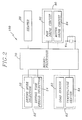
- FIG. 2 shows a schematic diagram of the control device 100 for controlling the drying process of the washing machine 10.
- the control device 100 comprises a switch pad 50, a detection block 60, a microprocessor 70, and a load drive circuit 90.
- the switch pad 50 and the detection block 60 are connected to the inputs of the microprocessor 70
- the load drive circuit 90 is connected to the outputs of the microprocessor 70.
- the switch pad 50 includes a drying mode selection switch 52 and a drying time period selection switch 54 for manually selecting a drying time period.
- a drying mode selection signal indicative of the drying process for the laundry articles to dry is issued to the microprocessor 70.
- the microprocessor 70 in response to the drying mode selection signal, executes the drying process for the drying time period manually selected by the drying time period selection switch 54 or a predetermined drying time period which will be discussed hereinafter.
- the detection block 60 includes a load sensor 62 for detecting the weight of the laundry articles in the rotatable tub 16 and a temperature sensor 64 for detecting the temperature in the rotatable tub 16.
- the load sensor 62 and the temperature sensor 64 as well known in the art, after detecting the weight and the temperature, issue a load signal indicative of the weight of laundry articles and a temperature signal indicative of the temperature to the microprocessor 70, respectively.
- the microprocessor 70 may be of any type suitable for such control purpose, which has a storage region therein or a separate memory device.
- the storage region may contain a plurality of drying control programs stored in the form of instructions and data. Each drying control program may be selected with the load signal from the load sensor 62.
- the microprocessor 70 may execute and process a series of instructions and data in response to the load signal to provide control signals to the load drive circuit 90.
- the load driving circuit 90 has a fan driving circuit 92 and a motor driving circuit 94.
- the fan driving circuit 92 is responsive to a fan control signal from the microprocessor 70 to enable the fan 28, shown in FIG. 1, to blow the heated air produced by the heater 26.
- the motor driving circuit 94 is responsive to a motor control signal from the microprocessor 70 to energize the motor 30 for the control of the pulsator 20.
- the motor control signal includes forward and reverse driving signals, which are repeatedly sent to the motor drive circuit 92 during the drying process. Accordingly, the motor 30 is alternately rotated in the forward and backward directions to cause forward and backward rotations of the pulsator 20.
- the motor 30 in the course of each of the forward and reverse direction rotations, is repeatedly subjected to the ON/OFF control to cause the pulsator 20 to periodically rotate and pause in each direction.
- the number N is preferably from 2 to 4, as will be illustrated below.
- the periodic repetition of rotation and pause of the pulsator 20 helps to untie or set loose the laundry items which may have been entangled during the dewatering process. It has been found that the laundry articles can be effectively untangled by rotating the pulsator 20 at an angle of not more than 180°, most preferably approximately 90°, from the pause state.
- the rotation of the pulsator 20 at the angle of 90° is achieved by turning the motor on for a time period "T1" of about 0.2 to 0.4 second.
- the periodic pause state between rotations of the pulsator 20 is employed to settle down the laundry articles which have been agitated during the rotation of the pulsator 20; and may continue for a time period "T2" ranging from about 0.3 to 1 second, preferably, 0.6 second.
- the motor 30 may preferably be controlled to a stop to have the pulsator 20 in an idle state for a predetermined time period "T3" after the completion of the periodic repetition for the N number of times before turning from the forward direction to the backward direction and vice versa.
- T3 time period for the pause state permits the heated air to sufficiently concentrate on the exposed portion of the laundry load to thereby improve the drying efficiency.
- the stop state of the motor 30 can be made to continue in time intervals of, e.g., about 20 to 30 seconds, preferably, 20 seconds.
- FIG. 3 is a graph showing the data for the different levels of dryness obtained by applying various conditions, which are empirically obtained by way of conducting the drying process with the N values of 2 and 3 and the intervals of 20 to 40 seconds. In this connection, it is assumed that the motor is rotated at the angle of 90° as set forth above.
- the data exhibits a higher level of dryness when the number N is 3 and the time period is 20 seconds.
- the number N is 4, 5, or higher.
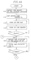
- FIGs. 4A and 4B there is illustrated a flow diagram explaining the operation of the drying process, wherein the control operation begins at block 112 where the weight of the laundry articles is detected by the load sensor 62 when the drying mode selection switch 52 is depressed by the user. The detected weight by the load sensor 62 is signaled to the microprocessor 70.
- step 114 the microprocessor 70 automatically sets a drying time period "T D " with the detected weight as listed in Table 1.
- the time period for drying may be also set as the one selected by the drying time period selection switch 54.
- step 116 and 118 the heater 26 and the fan 28 are driven under the control of the microprocessor 70 to heat ambient air and blow the heated air into the rotatable tub 16 through the inlet 42. And then the control process proceeds to step 120 where it is determined whether the temperature "H B " in the rotatable tub 16 reaches a predetermined temperature "H T " necessary to dry the laundry articles, e.g., a temperature of 30°C. If the temperature H B reaches the predetermined temperature H T , the control process flows to steps 122 and 124 where the pulsator 20 is rotated at an angle of 90° for the first predetermined time period "T1" and then paused for the second predetermined time period "T2".
- step 126 the repetitive rotation and pause states of the pulsator 20 are be repeated for the N number of times, e. g., 3. Thereafter, the control process goes to step 128 to make the pulsator 20 the idle state for the third predetermined time period "T 3".
- step 132 After the lapse of the third time period T3, the rotation direction of the motor 30 is changed to the reverse direction in step 130 and the control process advances to step 132.
- step 132 it is checked whether the time period "T S " spent to dry the laundry articles reaches the predetermined drying time period T D as set forth in step 114. If the test result is NO, the control process returns to step 122 and the operation as mentioned above is continued therefrom until the time period T S lapses the predetermined time period T D . If, however, the test result is YES, the control process goes to step 134 and then step 136 where each of the heater 26 and the fan 28 is turned off to finish the drying process.
Abstract
Description
- The present invention relates to a washing machine capable of washing, dewatering and drying a laundry article; and, more particularly, to a method for controlling a laundry dryer incorporated in the washing machine.
- Generally, there are two categories of washing machines which are in practical use for the purpose of washing laundry articles such as clothes. A first category involves a vortex-type washer wherein the laundry articles are subjected to a washing action as a pulsator therein rotates to generate a vortex flow within a washer tub. Such a vortex-type washer may encompass, in a broad sense, a stirrer-type washer wherein the laundry items are made to undergo vigorous frictional movement in the washing fluid by means of a bladed stirrer. Normally, the conventional vortex-type washer is not equipped with a drying mechanism therein.
- A second category involves a drum-type washer having a horizontal rotary drum partially submerged in a laundering water. With this type of washer, the laundry articles contained in the rotary drum are rubbed against each other as the drum rotates about its horizontal axis. U. S. Patent No. 5,058,401 issued to Fumio Nakamura et al. illustrates one of the second-type washers that can wash, dehydrate and dry the laundry. During the drying process of the laundry articles dewatered at a preceding dewatering process, an inner tub containing the dewatered laundry articles is rotated about a horizontal axis, heated air is supplied to the inner tub, and the laundry subjects are uniformly exposed to the hot air to dry.
- Conventionally, the heated air should be concentrated on a point of the dewatered laundry articles for at least 60 seconds in order to ensure them to dry. However, in the second-type washer, the hot air is distributed to the entire area of the inner tub due to its continuous revolution during the drying process, to thereby result in an extended drying time period and loss of power.
- It is, therefore, an object of the invention to provide a vortex-type washing machine having a laundry dryer therein.
- It is another object of the invention to provide a method for controlling the laundry dryer in the vortex-type washing machine during a drying process.
- In accordance with the present invention, there is provided an improved method for controlling a drying process of a vortex-type washing machine which has a tub capable of accommodating a laundry article for drying therein, a heating means, a pulsator rotatably mounted on the bottom surface of the tub, a motor for rotating the pulsator, wherein the method comprises the steps of: (A) providing heated air to the tub by using the heating means ; (B) driving the motor in a forward direction; (C) driving the motor in a backward direction; and (D) repeating the steps (B) and (C) until the laundry article becomes dried to a desired level. Further, each of the steps (B) and (C) includes the steps of: (a) turning on the motor to rotate the pulsator to spread the laundry article; (b) turning off the motor to pause the rotation of the pulsator to thereby help the settlement of the laundry article; and (c) repeating the steps (a) and (b) at least N number of times. The method further comprises, between the steps (B) and (C), a step of: (E) stopping the driving of the motor before the switching from the forward direction to the backward direction and vice versa for a predetermined period to expose the spread laundry article to the heated air.
- The above and other objects and features of the present invention will become apparent from the following description of preferred embodiments taken in conjunction with the accompanying drawings, in which:
- FIG. 1 shows a schematic sectional view of the overall structure of a vortex-type-washing machine equipped with a laundry dryer in accordance with the present invention;
- FIG. 2 illustrates a schematic block diagram of a control device in accordance with the present invention;
- FIG. 3 is a graph describing the relationship between the degree of drying and the drying efficiency; and
- FIGs. 4A and 4B are flow charts explaining the control sequence executed by the control device shown in Fig. 2.
- Referring now to FIG. 1, there is shown a washing machine equipped with a laundry dryer in accordance with the present invention. The
washing machine 10 comprises ahousing 12 and astationary washer tub 14 fixedly mounted within thehousing 12 for containing therein a level of washing fluid or detergent solution. Connected to the bottom of thestationary washer tub 14 are anelectrical motor 30 and aclutch assembly 32 coupled to theelectrical motor 30 by a belt-pulley assembly 34. As shown, theelectrical motor 30 and theclutch assembly 32 are both secured to thestationary washer tub 14 by means of suitable fastener means, e.g., welding or threading. Theelectrical motor 30 is capable of rotating depending upon the drying process, in a clockwise or counterclockwise direction, and, theclutch assembly 32 serves to selectively couple the driving force generated by theelectrical motor 30 with one of a first and a second drivenshafts - The first driven
shaft 36 carries at its top and arotatable washer tub 16 which is kept immovable during the washing process but is caused to rotate at a high speed during the dewatering process. Therotatable tub 16 is provided with, at its side wall, a plurality of washingfluid communication holes 40 permitting the washing fluid to flow into or out of therotatable tub 16. - Rotatably mounted on the bottom surface of the
rotatable tub 16 is apulsator 20 carried by the second drivenshaft 38. Thepulsator 20 is rotatable in a forward or backward direction to create a vortex flow within therotatable tub 16. - In a top portion of the
housing 12, there is provided aheater 26 for heating ambient air and afan 28 for blowing the heated air into therotatable tub 16 under the control of acontrol device 100. The air blown by thefan 28 is entered into therotatable tub 16 through aninlet 42 to circulate therein. After the completion of the circulation, a portion of the air is directly discharged via the top of therotatable tub 16 through anoutlet 46, and another portion of the air is discharged via theholes 40 and the passage between the top of therotatable tub 16 and the lid of thestationary tub 14 through theoutlet 46. - FIG. 2 shows a schematic diagram of the
control device 100 for controlling the drying process of thewashing machine 10. Thecontrol device 100 comprises aswitch pad 50, adetection block 60, amicroprocessor 70, and aload drive circuit 90. As shown in FIG. 2, theswitch pad 50 and thedetection block 60 are connected to the inputs of themicroprocessor 70, and theload drive circuit 90 is connected to the outputs of themicroprocessor 70. - The
switch pad 50 includes a dryingmode selection switch 52 and a drying timeperiod selection switch 54 for manually selecting a drying time period. When the drying mode is selected by the dryingmode selection switch 52 and the drying time period is set through the use of the drying timeperiod selection switch 54, a drying mode selection signal indicative of the drying process for the laundry articles to dry is issued to themicroprocessor 70. Themicroprocessor 70, in response to the drying mode selection signal, executes the drying process for the drying time period manually selected by the drying timeperiod selection switch 54 or a predetermined drying time period which will be discussed hereinafter. - The
detection block 60 includes aload sensor 62 for detecting the weight of the laundry articles in therotatable tub 16 and atemperature sensor 64 for detecting the temperature in therotatable tub 16. Theload sensor 62 and thetemperature sensor 64, as well known in the art, after detecting the weight and the temperature, issue a load signal indicative of the weight of laundry articles and a temperature signal indicative of the temperature to themicroprocessor 70, respectively. - The
microprocessor 70 may be of any type suitable for such control purpose, which has a storage region therein or a separate memory device. The storage region may contain a plurality of drying control programs stored in the form of instructions and data. Each drying control program may be selected with the load signal from theload sensor 62. Themicroprocessor 70 may execute and process a series of instructions and data in response to the load signal to provide control signals to theload drive circuit 90. - The
load driving circuit 90 has afan driving circuit 92 and amotor driving circuit 94. Thefan driving circuit 92 is responsive to a fan control signal from themicroprocessor 70 to enable thefan 28, shown in FIG. 1, to blow the heated air produced by theheater 26. Themotor driving circuit 94 is responsive to a motor control signal from themicroprocessor 70 to energize themotor 30 for the control of thepulsator 20. The motor control signal includes forward and reverse driving signals, which are repeatedly sent to themotor drive circuit 92 during the drying process. Accordingly, themotor 30 is alternately rotated in the forward and backward directions to cause forward and backward rotations of thepulsator 20. - In accordance with a preferred embodiment of the invention, in the course of each of the forward and reverse direction rotations, the
motor 30 is repeatedly subjected to the ON/OFF control to cause thepulsator 20 to periodically rotate and pause in each direction. - The periodic repetition of the rotation and the pause states of the
pulsator 20 is performed for N number of times whenever the rotation direction is reversely changed where N is a positive integer (N = 1, 2, 3,...). The number N is preferably from 2 to 4, as will be illustrated below. - The periodic repetition of rotation and pause of the
pulsator 20 helps to untie or set loose the laundry items which may have been entangled during the dewatering process. It has been found that the laundry articles can be effectively untangled by rotating thepulsator 20 at an angle of not more than 180°, most preferably approximately 90°, from the pause state. The rotation of thepulsator 20 at the angle of 90° is achieved by turning the motor on for a time period "T₁" of about 0.2 to 0.4 second. - The periodic pause state between rotations of the
pulsator 20 is employed to settle down the laundry articles which have been agitated during the rotation of thepulsator 20; and may continue for a time period "T₂" ranging from about 0.3 to 1 second, preferably, 0.6 second. - Further, the
motor 30 may preferably be controlled to a stop to have thepulsator 20 in an idle state for a predetermined time period "T₃" after the completion of the periodic repetition for the N number of times before turning from the forward direction to the backward direction and vice versa. The time period for the pause state permits the heated air to sufficiently concentrate on the exposed portion of the laundry load to thereby improve the drying efficiency. The stop state of themotor 30 can be made to continue in time intervals of, e.g., about 20 to 30 seconds, preferably, 20 seconds. - FIG. 3 is a graph showing the data for the different levels of dryness obtained by applying various conditions, which are empirically obtained by way of conducting the drying process with the N values of 2 and 3 and the intervals of 20 to 40 seconds. In this connection, it is assumed that the motor is rotated at the angle of 90° as set forth above.
- As can be seen from the graph, the data exhibits a higher level of dryness when the number N is 3 and the time period is 20 seconds. In addition, although it is not shown herein, essentially same results are obtained even if the number N is 4, 5, or higher.
- Referring now to FIGs. 4A and 4B, there is illustrated a flow diagram explaining the operation of the drying process, wherein the control operation begins at
block 112 where the weight of the laundry articles is detected by theload sensor 62 when the dryingmode selection switch 52 is depressed by the user. The detected weight by theload sensor 62 is signaled to themicroprocessor 70. - In
step 114, themicroprocessor 70 automatically sets a drying time period "TD" with the detected weight as listed in Table 1.Table 1 Weight of dried laundry articles(kg) Weight of dewatered laundry articles(kg) Time period(min.) 1 1.82 60 2 3.7 120 3 5.45 180 4 7.27 240
The time period for drying may be also set as the one selected by the drying timeperiod selection switch 54. - In
steps heater 26 and thefan 28 are driven under the control of themicroprocessor 70 to heat ambient air and blow the heated air into therotatable tub 16 through theinlet 42. And then the control process proceeds to step 120 where it is determined whether the temperature "HB" in therotatable tub 16 reaches a predetermined temperature "HT" necessary to dry the laundry articles, e.g., a temperature of 30°C. If the temperature HB reaches the predetermined temperature HT, the control process flows tosteps pulsator 20 is rotated at an angle of 90° for the first predetermined time period "T₁" and then paused for the second predetermined time period "T₂". - As in
step 126, the repetitive rotation and pause states of thepulsator 20 are be repeated for the N number of times, e. g., 3. Thereafter, the control process goes to step 128 to make thepulsator 20 the idle state for the third predetermined time period "T3". - After the lapse of the third time period T₃, the rotation direction of the
motor 30 is changed to the reverse direction instep 130 and the control process advances to step 132. - In
step 132, it is checked whether the time period "TS" spent to dry the laundry articles reaches the predetermined drying time period TD as set forth instep 114. If the test result is NO, the control process returns to step 122 and the operation as mentioned above is continued therefrom until the time period TS lapses the predetermined time period TD. If, however, the test result is YES, the control process goes to step 134 and then step 136 where each of theheater 26 and thefan 28 is turned off to finish the drying process. - While the present invention has been shown and described with respect to the preferred embodiments, it will be apparent to those skilled in the art that many changes and modifications may be made without departing from the spirit and scope of the invention as defined in the appended claims.
Claims (10)
- A method for controlling the drying process in a vortex-type washing machine having a tub accommodating a laundry article for drying therein, a heating means, a pulsator rotatably mounted on the bottom surface of the tub, a motor for rotating the pulsator, said method comprising the steps of:(A) providing heated air to the tub by using the heating means;(B) driving the motor in a forward direction;(C) driving the motor in a reverse direction; and(D) repeating the steps (B) to (C) until the laundry article becomes dried to a desired level, wherein each of the steps (B) and (C) includes the steps of:(a) turning on the motor to rotate the pulsator to spread the laundry article in the rotational tub;(b) turning off the motor to pause the rotation of the pulsator to thereby help the settlement of the laundry article; and(c) repeating the steps (a) to (b) at least N number of times.
- The method of claim 1, wherein said N is 2 or 3.
- The method of claim 1, wherein the method further comprises, between the steps (B) and (C), a step of:
(E) stopping the driving of the motor to cause the pulsator to stay in an idle state before switching from the forward direction to the reverse direction and vice versa for a predetermined time period to expose the spread laundry article to the heated air. - The method of claim 3, wherein, in the step (a), the pulsator is rotated by the motor at an angle of not more than 180°.
- The method of claim 4, wherein, in the step (a), the pulsator is rotated by the motor at an angle of about 90°.
- The method of claim 5, wherein, in the step (b), the pause state of the pulsator is carried out for a time period ranging from 0.3 to 1 second.
- The method of claim 6, wherein, in the step (b), the pause state of the pulsator is carried out for a time period of about 0.6 second.
- The method of claim 7, wherein, in the step (E), the idle state of the pulsator is continued for a time period ranging from 20 to 30 seconds.
- The method of claim 8, wherein, in the step (E), the idle state of the pulsator is continued for a time period of 20 seconds.
- The method of claim 1, wherein the method further comprises, before the step (A), a step of (F): setting a predetermined drying time period for drying the laundry article to the desired level.
Applications Claiming Priority (2)
| Application Number | Priority Date | Filing Date | Title |
|---|---|---|---|
| KR9402229 | 1994-02-07 | ||
| KR1019940002229A KR950025142A (en) | 1994-02-07 | 1994-02-07 | Drying control method of washing machine |
Publications (2)
| Publication Number | Publication Date |
|---|---|
| EP0666355A1 true EP0666355A1 (en) | 1995-08-09 |
| EP0666355B1 EP0666355B1 (en) | 1999-05-19 |
Family
ID=19376909
Family Applications (1)
| Application Number | Title | Priority Date | Filing Date |
|---|---|---|---|
| EP94118032A Expired - Lifetime EP0666355B1 (en) | 1994-02-07 | 1994-11-15 | Washing machine and method for controlling the drying process thereof |
Country Status (8)
| Country | Link |
|---|---|
| US (1) | US5537761A (en) |
| EP (1) | EP0666355B1 (en) |
| JP (1) | JP3011629B2 (en) |
| KR (1) | KR950025142A (en) |
| CN (1) | CN1063811C (en) |
| AU (1) | AU687901B2 (en) |
| DE (1) | DE69418589D1 (en) |
| TW (1) | TW264517B (en) |
Cited By (4)
| Publication number | Priority date | Publication date | Assignee | Title |
|---|---|---|---|---|
| EP1813706A1 (en) * | 2006-01-26 | 2007-08-01 | Samsung Electronics Co., Ltd. | Washing and drying machine and method for controlling the same |
| US8297082B2 (en) | 2008-04-30 | 2012-10-30 | Lg Electronics Inc. | Laundry machine |
| US8307567B2 (en) | 2008-04-30 | 2012-11-13 | Lg Electronics Inc. | Laundry machine |
| US8677785B2 (en) | 2008-04-30 | 2014-03-25 | Lg Electronics Inc. | Laundry machine |
Families Citing this family (14)
| Publication number | Priority date | Publication date | Assignee | Title |
|---|---|---|---|---|
| KR970075043A (en) * | 1996-05-13 | 1997-12-10 | 구자홍 | How to control dehydration of washing machine |
| US5940988A (en) * | 1998-02-23 | 1999-08-24 | Eisen; Daniel | Apparatus and method for dry cleaning |
| EP0942093B1 (en) * | 1998-03-12 | 2004-12-29 | Matsushita Electric Industrial Co., Ltd. | Electric washer-dryer |
| US6006445A (en) * | 1998-09-03 | 1999-12-28 | Large; Ronald D. | Washer/dryer combination |
| KR100689338B1 (en) * | 2001-01-16 | 2007-03-08 | 주식회사 엘지이아이 | The rinse method for a washing machine |
| JP2002233685A (en) * | 2001-02-13 | 2002-08-20 | Matsushita Electric Ind Co Ltd | Washing and drying machine |
| JP2004313515A (en) * | 2003-04-17 | 2004-11-11 | Toshiba Corp | Washing machine |
| US7571553B2 (en) * | 2006-12-01 | 2009-08-11 | Electrolux Home Products, Inc. | Control user interface for laundry appliances |
| CN101285260B (en) * | 2007-04-09 | 2012-09-19 | 海尔集团公司 | Process for drying by imitating sunlight with drying structure of laundry machine and removing ozone by catalyzed sorption |
| US8104191B2 (en) | 2008-07-31 | 2012-01-31 | Electrolux Home Products, Inc. | Laundry dryer providing moisture application during tumbling and reduced airflow |
| JP2011045776A (en) * | 2010-12-07 | 2011-03-10 | Mitsubishi Electric Corp | Washing and drying machine |
| US8959794B2 (en) * | 2011-10-18 | 2015-02-24 | Roderich W. Graeff | Process and apparatus to control the airflow in dehumidifying dryers |
| JP6736805B2 (en) * | 2015-12-11 | 2020-08-05 | 青島海爾洗衣机有限公司QingDao Haier Washing Machine Co.,Ltd. | Washing and drying machine |
| KR20170082033A (en) * | 2016-01-05 | 2017-07-13 | 엘지전자 주식회사 | Dish washer and controlling method thereof |
Citations (2)
| Publication number | Priority date | Publication date | Assignee | Title |
|---|---|---|---|---|
| US2818719A (en) * | 1952-05-19 | 1958-01-07 | Kermit R Cline | Combined washing and drying apparatus |
| US3091955A (en) * | 1961-10-26 | 1963-06-04 | Gen Motors Corp | Combination clothes washer and drier |
Family Cites Families (8)
| Publication number | Priority date | Publication date | Assignee | Title |
|---|---|---|---|---|
| JPS58221996A (en) * | 1982-06-17 | 1983-12-23 | 松下電器産業株式会社 | Control apparatus of dryer |
| US5111673A (en) * | 1988-06-20 | 1992-05-12 | Matsushita Electric Industrial Co. Ltd. | Washing-drying machine |
| US5058401A (en) * | 1988-12-22 | 1991-10-22 | Brother Kogyo Kabushiki Kaisha | Washing, dehydrating and drying machine |
| JP2749371B2 (en) * | 1989-05-20 | 1998-05-13 | 株式会社日立製作所 | Fully automatic washing / drying machine |
| US5291667A (en) * | 1990-04-26 | 1994-03-08 | White Consolidated Industries, Inc. | Electronic control of clothes dryer |
| US5226291A (en) * | 1991-12-17 | 1993-07-13 | General Motors Corporation | Vacuum booster diaphragm/support plate retention method |
| CN2116020U (en) * | 1992-02-25 | 1992-09-16 | 徐辉 | Dewatering drier |
| JPH05277294A (en) * | 1992-03-31 | 1993-10-26 | Toshiba Corp | Drier for clothes |
-
1994
- 1994-02-07 KR KR1019940002229A patent/KR950025142A/en not_active Application Discontinuation
- 1994-11-15 AU AU78830/94A patent/AU687901B2/en not_active Ceased
- 1994-11-15 DE DE69418589T patent/DE69418589D1/en not_active Expired - Lifetime
- 1994-11-15 EP EP94118032A patent/EP0666355B1/en not_active Expired - Lifetime
- 1994-11-17 TW TW083110687A patent/TW264517B/zh active
- 1994-11-17 US US08/340,949 patent/US5537761A/en not_active Expired - Fee Related
- 1994-12-13 JP JP6308806A patent/JP3011629B2/en not_active Expired - Fee Related
-
1995
- 1995-01-19 CN CN95101247A patent/CN1063811C/en not_active Expired - Fee Related
Patent Citations (2)
| Publication number | Priority date | Publication date | Assignee | Title |
|---|---|---|---|---|
| US2818719A (en) * | 1952-05-19 | 1958-01-07 | Kermit R Cline | Combined washing and drying apparatus |
| US3091955A (en) * | 1961-10-26 | 1963-06-04 | Gen Motors Corp | Combination clothes washer and drier |
Cited By (5)
| Publication number | Priority date | Publication date | Assignee | Title |
|---|---|---|---|---|
| EP1813706A1 (en) * | 2006-01-26 | 2007-08-01 | Samsung Electronics Co., Ltd. | Washing and drying machine and method for controlling the same |
| US8297082B2 (en) | 2008-04-30 | 2012-10-30 | Lg Electronics Inc. | Laundry machine |
| US8307567B2 (en) | 2008-04-30 | 2012-11-13 | Lg Electronics Inc. | Laundry machine |
| US8387419B2 (en) | 2008-04-30 | 2013-03-05 | Lg Electronics Inc. | Laundry machine |
| US8677785B2 (en) | 2008-04-30 | 2014-03-25 | Lg Electronics Inc. | Laundry machine |
Also Published As
| Publication number | Publication date |
|---|---|
| KR950025142A (en) | 1995-09-15 |
| TW264517B (en) | 1995-12-01 |
| JP3011629B2 (en) | 2000-02-21 |
| CN1111302A (en) | 1995-11-08 |
| CN1063811C (en) | 2001-03-28 |
| JPH07222888A (en) | 1995-08-22 |
| AU7883094A (en) | 1995-08-17 |
| EP0666355B1 (en) | 1999-05-19 |
| AU687901B2 (en) | 1998-03-05 |
| DE69418589D1 (en) | 1999-06-24 |
| US5537761A (en) | 1996-07-23 |
Similar Documents
| Publication | Publication Date | Title |
|---|---|---|
| EP0666355B1 (en) | Washing machine and method for controlling the drying process thereof | |
| CA2053445C (en) | Tumbler type washing/drying machine and method of controlling the same | |
| EP0796942B1 (en) | Washer-dryer apparatus | |
| EP1489217B1 (en) | Semi-drying method in washing machine and washing machine | |
| EP0957194B1 (en) | A method of washing laundry | |
| EP1526210B1 (en) | Washing machine control method | |
| EP0742307A1 (en) | Drum type washing machine and washing method thereof | |
| US5890247A (en) | Automatic washing machine incorporating a suds detection and control system | |
| EP0829569A2 (en) | Washer-dryer apparatus | |
| JP3011636B2 (en) | Drum type washing machine | |
| JP3296712B2 (en) | Washing method and rotating drum type fully automatic washing machine | |
| KR20020057119A (en) | Washing method for washing machine | |
| US7698768B2 (en) | Drum type washing machine with laundry drying function and method for controlling the same | |
| JP2004351073A (en) | Drum type washing and drying machine | |
| JP3734326B2 (en) | Drum type electric washing machine | |
| US20040154643A1 (en) | Method of controlling combination washer drier | |
| JPH10295978A (en) | Drum type washing machine | |
| KR0175232B1 (en) | Drying method for a washing machine | |
| KR20050012451A (en) | Method of semi-dry for washer | |
| JPH0292394A (en) | Drum type washing and drying machine | |
| JPH11169580A (en) | Drum type washing/drying machine | |
| KR100977568B1 (en) | Method for semi-dry in washer | |
| JP2002360966A (en) | Washing and drying machine | |
| JPH09182887A (en) | Drum type washing machine | |
| JP2003320194A (en) | Washing-drying machine |
Legal Events
| Date | Code | Title | Description |
|---|---|---|---|
| PUAI | Public reference made under article 153(3) epc to a published international application that has entered the european phase |
Free format text: ORIGINAL CODE: 0009012 |
|
| AK | Designated contracting states |
Kind code of ref document: A1 Designated state(s): DE FR GB |
|
| 17P | Request for examination filed |
Effective date: 19960207 |
|
| 17Q | First examination report despatched |
Effective date: 19970526 |
|
| GRAG | Despatch of communication of intention to grant |
Free format text: ORIGINAL CODE: EPIDOS AGRA |
|
| GRAG | Despatch of communication of intention to grant |
Free format text: ORIGINAL CODE: EPIDOS AGRA |
|
| GRAH | Despatch of communication of intention to grant a patent |
Free format text: ORIGINAL CODE: EPIDOS IGRA |
|
| GRAH | Despatch of communication of intention to grant a patent |
Free format text: ORIGINAL CODE: EPIDOS IGRA |
|
| GRAA | (expected) grant |
Free format text: ORIGINAL CODE: 0009210 |
|
| AK | Designated contracting states |
Kind code of ref document: B1 Designated state(s): DE FR GB |
|
| REF | Corresponds to: |
Ref document number: 69418589 Country of ref document: DE Date of ref document: 19990624 |
|
| ET | Fr: translation filed | ||
| PG25 | Lapsed in a contracting state [announced via postgrant information from national office to epo] |
Ref country code: DE Free format text: LAPSE BECAUSE OF FAILURE TO SUBMIT A TRANSLATION OF THE DESCRIPTION OR TO PAY THE FEE WITHIN THE PRESCRIBED TIME-LIMIT Effective date: 19990820 |
|
| PLBE | No opposition filed within time limit |
Free format text: ORIGINAL CODE: 0009261 |
|
| STAA | Information on the status of an ep patent application or granted ep patent |
Free format text: STATUS: NO OPPOSITION FILED WITHIN TIME LIMIT |
|
| 26N | No opposition filed | ||
| PGFP | Annual fee paid to national office [announced via postgrant information from national office to epo] |
Ref country code: GB Payment date: 20001115 Year of fee payment: 7 |
|
| PG25 | Lapsed in a contracting state [announced via postgrant information from national office to epo] |
Ref country code: GB Free format text: LAPSE BECAUSE OF NON-PAYMENT OF DUE FEES Effective date: 20011115 |
|
| REG | Reference to a national code |
Ref country code: GB Ref legal event code: IF02 |
|
| REG | Reference to a national code |
Ref country code: FR Ref legal event code: TP |
|
| PGFP | Annual fee paid to national office [announced via postgrant information from national office to epo] |
Ref country code: FR Payment date: 20031110 Year of fee payment: 10 |
|
| PG25 | Lapsed in a contracting state [announced via postgrant information from national office to epo] |
Ref country code: FR Free format text: LAPSE BECAUSE OF NON-PAYMENT OF DUE FEES Effective date: 20050729 |
|
| REG | Reference to a national code |
Ref country code: FR Ref legal event code: ST |