EP0666086A1 - Guide wire for medical purpose and manufacturing process of coil thereof - Google Patents
Guide wire for medical purpose and manufacturing process of coil thereof Download PDFInfo
- Publication number
- EP0666086A1 EP0666086A1 EP94101605A EP94101605A EP0666086A1 EP 0666086 A1 EP0666086 A1 EP 0666086A1 EP 94101605 A EP94101605 A EP 94101605A EP 94101605 A EP94101605 A EP 94101605A EP 0666086 A1 EP0666086 A1 EP 0666086A1
- Authority
- EP
- European Patent Office
- Prior art keywords
- coil
- wire
- wire rod
- shaft
- guide wire
- Prior art date
- Legal status (The legal status is an assumption and is not a legal conclusion. Google has not performed a legal analysis and makes no representation as to the accuracy of the status listed.)
- Granted
Links
Images


Classifications
-
- B—PERFORMING OPERATIONS; TRANSPORTING
- B21—MECHANICAL METAL-WORKING WITHOUT ESSENTIALLY REMOVING MATERIAL; PUNCHING METAL
- B21F—WORKING OR PROCESSING OF METAL WIRE
- B21F15/00—Connecting wire to wire or other metallic material or objects; Connecting parts by means of wire
- B21F15/02—Connecting wire to wire or other metallic material or objects; Connecting parts by means of wire wire with wire
- B21F15/06—Connecting wire to wire or other metallic material or objects; Connecting parts by means of wire wire with wire with additional connecting elements or material
-
- A—HUMAN NECESSITIES
- A61—MEDICAL OR VETERINARY SCIENCE; HYGIENE
- A61M—DEVICES FOR INTRODUCING MEDIA INTO, OR ONTO, THE BODY; DEVICES FOR TRANSDUCING BODY MEDIA OR FOR TAKING MEDIA FROM THE BODY; DEVICES FOR PRODUCING OR ENDING SLEEP OR STUPOR
- A61M25/00—Catheters; Hollow probes
- A61M25/01—Introducing, guiding, advancing, emplacing or holding catheters
- A61M25/09—Guide wires
-
- B—PERFORMING OPERATIONS; TRANSPORTING
- B21—MECHANICAL METAL-WORKING WITHOUT ESSENTIALLY REMOVING MATERIAL; PUNCHING METAL
- B21C—MANUFACTURE OF METAL SHEETS, WIRE, RODS, TUBES OR PROFILES, OTHERWISE THAN BY ROLLING; AUXILIARY OPERATIONS USED IN CONNECTION WITH METAL-WORKING WITHOUT ESSENTIALLY REMOVING MATERIAL
- B21C37/00—Manufacture of metal sheets, bars, wire, tubes or like semi-manufactured products, not otherwise provided for; Manufacture of tubes of special shape
- B21C37/04—Manufacture of metal sheets, bars, wire, tubes or like semi-manufactured products, not otherwise provided for; Manufacture of tubes of special shape of bars or wire
- B21C37/042—Manufacture of coated wire or bars
-
- B—PERFORMING OPERATIONS; TRANSPORTING
- B21—MECHANICAL METAL-WORKING WITHOUT ESSENTIALLY REMOVING MATERIAL; PUNCHING METAL
- B21F—WORKING OR PROCESSING OF METAL WIRE
- B21F15/00—Connecting wire to wire or other metallic material or objects; Connecting parts by means of wire
- B21F15/02—Connecting wire to wire or other metallic material or objects; Connecting parts by means of wire wire with wire
- B21F15/06—Connecting wire to wire or other metallic material or objects; Connecting parts by means of wire wire with wire with additional connecting elements or material
- B21F15/08—Connecting wire to wire or other metallic material or objects; Connecting parts by means of wire wire with wire with additional connecting elements or material making use of soldering or welding
-
- B—PERFORMING OPERATIONS; TRANSPORTING
- B21—MECHANICAL METAL-WORKING WITHOUT ESSENTIALLY REMOVING MATERIAL; PUNCHING METAL
- B21F—WORKING OR PROCESSING OF METAL WIRE
- B21F35/00—Making springs from wire
-
- B—PERFORMING OPERATIONS; TRANSPORTING
- B21—MECHANICAL METAL-WORKING WITHOUT ESSENTIALLY REMOVING MATERIAL; PUNCHING METAL
- B21F—WORKING OR PROCESSING OF METAL WIRE
- B21F45/00—Wire-working in the manufacture of other particular articles
-
- B—PERFORMING OPERATIONS; TRANSPORTING
- B21—MECHANICAL METAL-WORKING WITHOUT ESSENTIALLY REMOVING MATERIAL; PUNCHING METAL
- B21F—WORKING OR PROCESSING OF METAL WIRE
- B21F45/00—Wire-working in the manufacture of other particular articles
- B21F45/008—Wire-working in the manufacture of other particular articles of medical instruments, e.g. stents, corneal rings
-
- A—HUMAN NECESSITIES
- A61—MEDICAL OR VETERINARY SCIENCE; HYGIENE
- A61M—DEVICES FOR INTRODUCING MEDIA INTO, OR ONTO, THE BODY; DEVICES FOR TRANSDUCING BODY MEDIA OR FOR TAKING MEDIA FROM THE BODY; DEVICES FOR PRODUCING OR ENDING SLEEP OR STUPOR
- A61M25/00—Catheters; Hollow probes
- A61M25/01—Introducing, guiding, advancing, emplacing or holding catheters
- A61M25/09—Guide wires
- A61M2025/09166—Guide wires having radio-opaque features
-
- A—HUMAN NECESSITIES
- A61—MEDICAL OR VETERINARY SCIENCE; HYGIENE
- A61M—DEVICES FOR INTRODUCING MEDIA INTO, OR ONTO, THE BODY; DEVICES FOR TRANSDUCING BODY MEDIA OR FOR TAKING MEDIA FROM THE BODY; DEVICES FOR PRODUCING OR ENDING SLEEP OR STUPOR
- A61M25/00—Catheters; Hollow probes
- A61M25/01—Introducing, guiding, advancing, emplacing or holding catheters
- A61M25/09—Guide wires
- A61M2025/09175—Guide wires having specific characteristics at the distal tip
Definitions
- the present invention relates to a guide wire for medical purpose used for introducing a catheter into a blood vessel system, especially into a human heart blood vessel system, and a manufacturing process of a coil constituting the guide wire.
- a guide wire For the purpose of introducing a catheter into a blood system for angiography, conventionally a guide wire has been used to more safely and more accurately carry out the introduction.
- the guide wire is effective to relatively thick blood vessels or those having relatively simple branches or bending in a relatively simple form, but sometimes it is very difficult to carry a catheter into a depth of a blood vessel branching very minutely such as a coronary of a human heart, and especially for substantially stenosed portions a guide wire based on a completely different concept is required.
- a portion near a tip of the guide wire should be opaque against radioactive rays such as X-ray in order to accurately detect a stenosed portion.
- a guide wire as disclosed, for instance, in Japanese Patent Publication NO. 25024/1992 has been proposed.
- Fig.1A and Fig.1B each diagramatically illustrating the situations where the problem as described occurs, if the connected section 51 of the guide wire 50 is too hard, it can not follow bending of a blood vessel 52 and can not pass through the section (Fig.1A), and on the other hand, if the connected section 51 is too soft, it bends and passage becomes impossible also in this case (Fig.1B).
- the present invention was made in the light of the circumstances as described above, and it is an object of the present invention to provide a guide wire for medical purposes which has no connection and can pass through even a blood vessel having an extremely small curvature.
- a guide wire for medical purposes is a guide wire for medical purposes having a proximal section and a distal section, wherein all or a portion of slender and flexible shaft is inserted into and fixed in a coil to achieve the above-described object, the coil is a multiple-wire coil comprising at least two or more wire rods, of these wire rods at least one wire rod is made of a radiopaque material, and a portion of the coil closer to the distal section of the shaft is a single-wire coil made of the radiopaque material.
- the radiopaque material is made of any of alloy containing platinum as a main component, alloy containing gold as a main component, alloy containing tungsten as a main component, and lead.
- a portion of single-wire coil consisting of a wire rod made of the radiopaque material and an edge portion consisting of a different wire rod are contacted and fixed to each other by means of soldering.
- the distal section of the shaft comprises two portions jointed to each other in the axial direction.
- a guide wire for medical purposes is a guide wire for medical purposes having a proximal section and a distal section, wherein all or a portion of slender and flexible shaft is inserted into and fixed in a coil to achieve the above-described object, the coil is a single-wire one consisting of one wire rod having no connection, and a portion of this coil closer to the distal section of the shaft is made of the material opaque against radioactive rays such as X ray.
- a wire rod of a coil comprises an inner layer and an outer layer, and a portion of the inner layer closer to the distal section of the shaft is made of radiopaque material, and the outer layer and a portion of the inner layer other than that closer to the distal section of the shaft is made of a radiotransparent material.
- the radiopaque material is made of any of alloy containing platinum as a main component, alloy containing gold as a main component, alloy containing tungsten as a main component, and lead.
- the coil is a multiple-wire coil consisting of at least 2 wire rods each having no connection or a single-wire coil consisting of a wire rod having no connection, so that the coil has no remarkable irregularity in bending radius when bent like that of a conventional type of guide wire having a connection and the bending ratio is kept at a constant level, so that the coil can easily pass through even a minute blood vessel having an extremely small curvature.
- a portion of coil closer to the shaft distal section is made of a radiopaque material, when fluoroscopy is carried out, the section can easily be distinguished from the surrounding minute vessel, and also a position of the guide wire itself can easily be detected clearly. For this reason, a guide wire can easily be passed through even a blood vessel having an extremely small curvature, and is convenient especially when introducing a catheter into a minute blood vessel such as those in a human heart.
- a wire rod made of a radiotransparent material and a wire rod made of a radiopaque material are jointed by soldering one edge section of a wire rod to an opposing edge section of another wire rod, and these jointed two wire rods are pulled through a die to make them into a wire rod having a smaller diameter, which is manufactured into a coil.
- a wire rod made of a radiopaque material is inserted into one side of the thin tubular outer layer made of a radiotransparent material and a wire rod made of a material which is the same as that of the outer layer is inserted into the other side thereof, and then the complex layer is pulled through a die to form a wire rod having a small diameter, which is manufactured into a coil.
- a coil constituting a guide wire can easily be manufactured.
- a guide wire which comprises a slender and flexible shaft 2 made of such a material as stainless steel, a coil 3, and a plug 4.
- the shaft 2 comprises a proximal section 2a, a distal section 2b and an intermediate section 2c, and the intermediate section 2c and the distal section 2b are tapered toward the plug 4 by means of polishing.
- a length L1 of the proximal section 2a of the shaft 2 is 1400 mm, while a length L2 of other portion thereof is 350 mm, so the full length L3 is 1750 mm.
- the proximal section 2a has a cylindrical form having a diameter D1 of 0.35 mm.
- the intermediate section 2c comprises a cylindrical form section 2e with the diameter reduced via the tapered section 2d to D2 of 0.19 mm and a cylindrical form section 2g with the diameter reduced via the tapered section 2f to D3 of 0.13 mm, and the cylindrical distal section 2b with the diameter reduced via the tapered section 2h at the tip of this cylindrical section 2g to 0.05 mm is provided monolithically.
- the plug 4 having a roundness toward the tip.
- the coil 3 is a multi-stripe one consisting of 3 wire rods each having no connection like that in the conventional type of coil.
- a wire rod 3a is made of a heavy metal such as, for instance, alloy containing platinum as a main component, alloy containing gold as a main component, alloy containing tungsten as a main component, or lead, and other two wire rods 3b, 3c are made of a material such as stainless steel, SUS 304, etc., which X ray can pass through.
- the coil 3 is a single-wire one consisting of only wire rod 3a in the portion closer to the distal section 2b of the shaft 2, because the wire rods 3b and 3c are gradually reduced and finally disappear in this portion.
- the coil 3 can maintain the bending ratio at a constant level.
- the number of wires in the coil 3 should be decided in a range where a black stripe, which is formed by the wire rod 3a made of a radiopaque material, is practically effective when actually fluoroscoped. But the number should preferably be not more than 6.
- a tip of wire rod 3a made of a radiopaque material is fixed to the plug 4 in the distal section 2b of the shaft 2, while a base of the opposite side is fixed to the tapered section 2d of the shaft 1.
- a portion 5 shadowed with inclined lines is a soldered connection filled in a gap formed between edge sections of wire rods 3b,3c each gradually decreasing and the wire rod 3a formed into a single-wire coil, and without this soldered connection 5, homogeneity in bending may be lost when inserted into a blood vessel, or blood may easily come into the coil 3, which may become a cause of thrombosis, but these problems can be solved by filling the soldered connection 5 in the gap. Also, by filling the solder connection 5 therein, the distal section 2b of the shaft 2 is soldered to the coil 3, so that the fixation between the coil 3 and the shaft 2 is more tightly and more safely performed.
- the guide wire 1 having the configuration as described above When the guide wire 1 having the configuration as described above is inserted into a blood vessel 22 having an extremely small curvature as shown in Fig.3, the guide wire smoothly advances in a blood vessel 52 and passes through even a bending section. This is because the coil 3 has no connection like that in a conventional type of coil and the bending ratio thereof is maintained at a constant level. Also, in the guide wire 1, the wire rod 3a for coil 3 made of a radiopaque material is shown under fluoroscopy with X ray as a black section in the distal section and as spaced black stripes in other section where the wire rod 3a is coiled together with other wire rods 3b,3c, so that an operator can quite easily distinguish the guide wire from the surrounding blood vessel 22. For this reason, the operator can recognize a bending section positional relations in a stenosed section in the blood vessel 52 with the help by contrast media discharged from a catheter, and also can recognize the position of the guide wire 1 itself quite clearly.
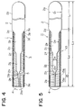
- Fig.4 is a drawing illustrating an example of another formation of the shaft, and the distal section 2b of this shaft 2 comprises two portions. Namely, a distal section 2b1 provided via a tapered section 2h of the cylindrical portion 2g forms a short section, and a cylindrical distal section 2b2 which is an independent body having almost the same length as that of the distal section 2b shown in Fig.1 is jointed with and fixed to the distal section 2b1 in the axial direction. Other portions in this configuration are the same as those in Fig.2.
- a coil 13 is a single-wire one consisting of one wire rod having no connection.
- a portion of a wire rod 15 constituting the coil 13 closer to the distal section 2b of the shaft 2 consists of a wire rod 15a made of a material which is different from such a material as stainless steel and X ray can not pass through; namely in this case such a heavy metal as alloy containing platinum as a main component, alloy containing gold as a main component, alloy containing tungsten as a main component, or lead, while a portion of a wire rod 15 other than the portion closer to the distal section 2b of the shaft 2 consists of a wire rod 15b made of a material which has the same quality as stainless steel or the like or such a material as copper which can industrially be utilized and X ray can pass through.
- Configuration in other portions of the shaft 2 is the same as that in the embodiment shown in Fig.2. Also with this guide wire 11, the same effect
- an edge section of the wire rod 15a made of a radiopaque material is moved closer to an opposite edge section of the wire rod 15b made of a radiotransparent material (A).
- the both edge faces are contacted and fixed by means of weldering, and then the metal thrusting toward the radial direction is removed to real-ize a smooth surface (B,C).
- the wire rods 15a, 15b fixed to each other is pulled through a die 18 to obtain a wire rod having a smaller diameter, which is finished to a wire rod 15 having a necessary outer diameter (D,E).
- Outer diameter of the wire rod 15 is preferably in a range from 0.03 to 0.15 mm.
- formed is the continuous and homogeneous coil 13 consisting of the wire rod 15, of which a portion is radiopaque (F).
- a wire rod 29 constituting a coil 23 of a guide wire 21 in this embodiment comprises an inner layer 25 and an outer layer 26.
- the outer layer 26 is made of such a material as stainless steel and has a tubular form, while a portion of the inner layer 25 closer to the distal section 2b of the shaft 2 is made of a material 25a which is different from such a material as stainless steel and X ray can not pass through; namely in this case such a material as alloy containing platinum as a main component, alloy containing gold as a main component, alloy containing tungsten as a main component, or lead, while a portion of the inner layer 25 other than the portion closer to the distal section 2b of the shaft 2 is made of a material 25b which has the same quality as stainless steel or of a material like copper which can industrially be utilized and X ray can pass through.
- Configuration of the shaft 2 in other portions is the same as that in the embodiment shown in Fig.2.
- the slender and tubular outer layer 26 is formed with such a material as stainless steel SUS 304 (A), and the wire rod 25a made of such a metal or other radiopaque material as described above is inserted from one side of this outer layer 26.
- a wire rod 25b made of a material which has the same quality as stainless steel or other material constituting the outer layer 26 or of a radiotransparent material like copper which can industrially be utilized is inserted into the outer layer 26 from the other side thereof, and an edge face at the tip thereof is moved closer and contacted to that of the wire rod 25a (B,C).
- the complex layer comprising the outer layer 26 and the inner layer 25 formed as described above is pulled through a die 28 to obtain a wire rod having a smaller diameter, which is finished to a wire rod 29 having a necessary outer diameter (D,E).
- the outer diameter of the wire rod 29 is preferably in a range from 0.03 to 0.15 mm like in the embodiment shown in Fig.5. Assuming that 1 is a cross-sectional area of the wire rod 29 in the portion with the wire rod 25a made of a radiopaque material, it is preferable that a cross-sectional area of the wire rod 25b made of a radiotransparent mate rial and constituting the inner layer 25 is 0.2 or more. Then, by coiling the wire rod 29 formed as described above, the continuous and homogeneous coil 23, in which X ray can not pass through a portion of the inner layer 25, is formed as shown in (F).
- the wire rod 25b as the inner layer 25 made of a radiotransparent material is not always necessary and the portion may be hollow.
- a radiotransparent material for the wire rod 25b is not always limited to a metal, and non-metallic material such as powder of barium sulfate or bismuth oxide, or other substance in a solidified state may be used for that purpose.
- the tip of the wire rod 25a made of a radiopaque material is fixed to the plug 4, while a proximal edge of the wire rod 25b made of a radiotransparent material is fixed to the tapered section 2d of the shaft 1.
- the distal section 2b of the shaft 2 may comprise 2 portions like in the embodiment shown in Fig.4.
Abstract
Description
- The present invention relates to a guide wire for medical purpose used for introducing a catheter into a blood vessel system, especially into a human heart blood vessel system, and a manufacturing process of a coil constituting the guide wire.
- For the purpose of introducing a catheter into a blood system for angiography, conventionally a guide wire has been used to more safely and more accurately carry out the introduction. The guide wire is effective to relatively thick blood vessels or those having relatively simple branches or bending in a relatively simple form, but sometimes it is very difficult to carry a catheter into a depth of a blood vessel branching very minutely such as a coronary of a human heart, and especially for substantially stenosed portions a guide wire based on a completely different concept is required. Especially in case of guide wire used for a catheter for blood vessel forming in substantially stenosed sections, it is essential that a portion near a tip of the guide wire should be opaque against radioactive rays such as X-ray in order to accurately detect a stenosed portion. To achieve the object as described above, a guide wire as disclosed, for instance, in Japanese Patent Publication NO. 25024/1992 has been proposed.
- In the conventional type of guide wire as described above, 2 pieces of coil are connected to a section near a tip of shaft made of metal having a high twistability, and of the two pieces of coil, the one closer to the tip is made of a radiopaque material so that the guide wire will be provided with high flexibility and high bending capability as well as be easily detected by radioactive rays, through introduced various devices. However, in this type of guide wire, 2 coils made of different materials are artificially coupled and connected by means of screwing or soldering, so particular considerations are required to maintain mechanical safety and strength in the connected section, and in addition, because mechanical characteristics of the connected section becomes discontinuing, when a guide wire passes through a blood vessel having an extremely small curvature, sometimes passage becomes impossible due to discontinuity of bending radius in this connected section. Namely in Fig.1A and Fig.1B each diagramatically illustrating the situations where the problem as described occurs, if the connected
section 51 of theguide wire 50 is too hard, it can not follow bending of ablood vessel 52 and can not pass through the section (Fig.1A), and on the other hand, if the connectedsection 51 is too soft, it bends and passage becomes impossible also in this case (Fig.1B). - The present invention was made in the light of the circumstances as described above, and it is an object of the present invention to provide a guide wire for medical purposes which has no connection and can pass through even a blood vessel having an extremely small curvature.
- A guide wire for medical purposes according to this invention is a guide wire for medical purposes having a proximal section and a distal section, wherein all or a portion of slender and flexible shaft is inserted into and fixed in a coil to achieve the above-described object, the coil is a multiple-wire coil comprising at least two or more wire rods, of these wire rods at least one wire rod is made of a radiopaque material, and a portion of the coil closer to the distal section of the shaft is a single-wire coil made of the radiopaque material. In one mode of carrying out this invention, the radiopaque material is made of any of alloy containing platinum as a main component, alloy containing gold as a main component, alloy containing tungsten as a main component, and lead.
- Furthermore in another embodiment of the present invention, a portion of single-wire coil consisting of a wire rod made of the radiopaque material and an edge portion consisting of a different wire rod are contacted and fixed to each other by means of soldering. Furthermore in a different embodiment of the present invention, the distal section of the shaft comprises two portions jointed to each other in the axial direction.
- A guide wire for medical purposes according to this invention is a guide wire for medical purposes having a proximal section and a distal section, wherein all or a portion of slender and flexible shaft is inserted into and fixed in a coil to achieve the above-described object, the coil is a single-wire one consisting of one wire rod having no connection, and a portion of this coil closer to the distal section of the shaft is made of the material opaque against radioactive rays such as X ray. And in a still different embodiment of the present invention, a wire rod of a coil comprises an inner layer and an outer layer, and a portion of the inner layer closer to the distal section of the shaft is made of radiopaque material, and the outer layer and a portion of the inner layer other than that closer to the distal section of the shaft is made of a radiotransparent material.
- In the different embodiment of the present invention, the radiopaque material is made of any of alloy containing platinum as a main component, alloy containing gold as a main component, alloy containing tungsten as a main component, and lead.
- Namely in the invention as described above, the coil is a multiple-wire coil consisting of at least 2 wire rods each having no connection or a single-wire coil consisting of a wire rod having no connection, so that the coil has no remarkable irregularity in bending radius when bent like that of a conventional type of guide wire having a connection and the bending ratio is kept at a constant level, so that the coil can easily pass through even a minute blood vessel having an extremely small curvature. Also as a portion of coil closer to the shaft distal section is made of a radiopaque material, when fluoroscopy is carried out, the section can easily be distinguished from the surrounding minute vessel, and also a position of the guide wire itself can easily be detected clearly. For this reason, a guide wire can easily be passed through even a blood vessel having an extremely small curvature, and is convenient especially when introducing a catheter into a minute blood vessel such as those in a human heart.
- Also it is an object of the present invention to provide a coil manufacturing method which makes it possible to produce a coil constituting the guide wire.
- In the coil manufacturing method according to the present invention, in order to achieve the object as described above, when producing coils each for a guide wire, a wire rod made of a radiotransparent material and a wire rod made of a radiopaque material are jointed by soldering one edge section of a wire rod to an opposing edge section of another wire rod, and these jointed two wire rods are pulled through a die to make them into a wire rod having a smaller diameter, which is manufactured into a coil. In one embodiment of the present invention, when manufacturing a coil for guide wire, a wire rod made of a radiopaque material is inserted into one side of the thin tubular outer layer made of a radiotransparent material and a wire rod made of a material which is the same as that of the outer layer is inserted into the other side thereof, and then the complex layer is pulled through a die to form a wire rod having a small diameter, which is manufactured into a coil. With these operations, a coil constituting a guide wire can easily be manufactured.
-
- Fig.1A and Fig.1B are drawings each illustrating effect of a conventional type of guide wire;
- Fig.2 is a longitudinal front sectional view of a guide wire illustrating an embodiment of the present invention, but lacking a portion thereof;
- Fig.3 is a drawing illustrating effect of a guide wire;
- Fig.4 is a longitudinal front sectional view of a guide wire illustrating another formation of the shaft, but lacking a portion thereof;
- Fig.5 is a longitudinal front sectional view of a guide wire illustrating another embodiment of the present invention, but lacking a portion thereof;
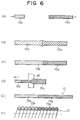
- Fig.6 is a schematic diagram illustrating a manufacturing process of the coil above;
- Fig.7 is a longitudinal front sectional view of a guide wire illustrating a further different embodiment of the present invention; and
- Fig.8 is a schematic diagram illustrating a manufacturing process of the coil above.
- In Fig. 2, designated at the reference numeral 1 is a guide wire, which comprises a slender and
flexible shaft 2 made of such a material as stainless steel, a coil 3, and aplug 4. Theshaft 2 comprises aproximal section 2a, adistal section 2b and anintermediate section 2c, and theintermediate section 2c and thedistal section 2b are tapered toward theplug 4 by means of polishing. A length L₁ of theproximal section 2a of theshaft 2 is 1400 mm, while a length L₂ of other portion thereof is 350 mm, so the full length L₃ is 1750 mm. Theproximal section 2a has a cylindrical form having a diameter D₁ of 0.35 mm. Theintermediate section 2c comprises acylindrical form section 2e with the diameter reduced via thetapered section 2d to D₂ of 0.19 mm and acylindrical form section 2g with the diameter reduced via thetapered section 2f to D₃ of 0.13 mm, and the cylindricaldistal section 2b with the diameter reduced via thetapered section 2h at the tip of thiscylindrical section 2g to 0.05 mm is provided monolithically. At the tip of thedistal section 2b is fixed theplug 4 having a roundness toward the tip. - The coil 3 is a multi-stripe one consisting of 3 wire rods each having no connection like that in the conventional type of coil. Of these, a
wire rod 3a is made of a heavy metal such as, for instance, alloy containing platinum as a main component, alloy containing gold as a main component, alloy containing tungsten as a main component, or lead, and other two wire rods 3b, 3c are made of a material such as stainless steel, SUS 304, etc., which X ray can pass through. Also the coil 3 is a single-wire one consisting of onlywire rod 3a in the portion closer to thedistal section 2b of theshaft 2, because the wire rods 3b and 3c are gradually reduced and finally disappear in this portion. As the wire rod 3b, 3c gradually decrease and finally disappear, the coil 3 can maintain the bending ratio at a constant level. The number of wires in the coil 3 should be decided in a range where a black stripe, which is formed by thewire rod 3a made of a radiopaque material, is practically effective when actually fluoroscoped. But the number should preferably be not more than 6. In the coil 3 formed as described above, a tip ofwire rod 3a made of a radiopaque material is fixed to theplug 4 in thedistal section 2b of theshaft 2, while a base of the opposite side is fixed to thetapered section 2d of the shaft 1. - In Fig.2, a
portion 5 shadowed with inclined lines is a soldered connection filled in a gap formed between edge sections of wire rods 3b,3c each gradually decreasing and thewire rod 3a formed into a single-wire coil, and without this solderedconnection 5, homogeneity in bending may be lost when inserted into a blood vessel, or blood may easily come into the coil 3, which may become a cause of thrombosis, but these problems can be solved by filling the solderedconnection 5 in the gap. Also, by filling thesolder connection 5 therein, thedistal section 2b of theshaft 2 is soldered to the coil 3, so that the fixation between the coil 3 and theshaft 2 is more tightly and more safely performed. - When the guide wire 1 having the configuration as described above is inserted into a blood vessel 22 having an extremely small curvature as shown in Fig.3, the guide wire smoothly advances in a
blood vessel 52 and passes through even a bending section. This is because the coil 3 has no connection like that in a conventional type of coil and the bending ratio thereof is maintained at a constant level. Also, in the guide wire 1, thewire rod 3a for coil 3 made of a radiopaque material is shown under fluoroscopy with X ray as a black section in the distal section and as spaced black stripes in other section where thewire rod 3a is coiled together with other wire rods 3b,3c, so that an operator can quite easily distinguish the guide wire from the surrounding blood vessel 22. For this reason, the operator can recognize a bending section positional relations in a stenosed section in theblood vessel 52 with the help by contrast media discharged from a catheter, and also can recognize the position of the guide wire 1 itself quite clearly. - Fig.4 is a drawing illustrating an example of another formation of the shaft, and the
distal section 2b of thisshaft 2 comprises two portions. Namely, a distal section 2b₁ provided via atapered section 2h of thecylindrical portion 2g forms a short section, and a cylindrical distal section 2b₂ which is an independent body having almost the same length as that of thedistal section 2b shown in Fig.1 is jointed with and fixed to the distal section 2b₁ in the axial direction. Other portions in this configuration are the same as those in Fig.2. - Fig.5 shows another embodiment of the present invention. In a guide wire 11 according to this embodiment, a
coil 13 is a single-wire one consisting of one wire rod having no connection. A portion of awire rod 15 constituting thecoil 13 closer to thedistal section 2b of theshaft 2 consists of awire rod 15a made of a material which is different from such a material as stainless steel and X ray can not pass through; namely in this case such a heavy metal as alloy containing platinum as a main component, alloy containing gold as a main component, alloy containing tungsten as a main component, or lead, while a portion of awire rod 15 other than the portion closer to thedistal section 2b of theshaft 2 consists of awire rod 15b made of a material which has the same quality as stainless steel or the like or such a material as copper which can industrially be utilized and X ray can pass through. Configuration in other portions of theshaft 2 is the same as that in the embodiment shown in Fig.2. Also with this guide wire 11, the same effect as that with the guide wire 1 can be expected. - To manufacture the
coil 13 as described above, as shown in Fig.6, at first an edge section of thewire rod 15a made of a radiopaque material is moved closer to an opposite edge section of thewire rod 15b made of a radiotransparent material (A). The both edge faces are contacted and fixed by means of weldering, and then the metal thrusting toward the radial direction is removed to real-ize a smooth surface (B,C). Then, thewire rods wire rod 15 having a necessary outer diameter (D,E). Outer diameter of thewire rod 15 is preferably in a range from 0.03 to 0.15 mm. Then by coiling thewire rod 15 manufactured as described above in the usual way, formed is the continuous andhomogeneous coil 13 consisting of thewire rod 15, of which a portion is radiopaque (F). - Fig.7 shows a further different embodiment of the present invention. A
wire rod 29 constituting acoil 23 of aguide wire 21 in this embodiment comprises an inner layer 25 and anouter layer 26. Theouter layer 26 is made of such a material as stainless steel and has a tubular form, while a portion of the inner layer 25 closer to thedistal section 2b of theshaft 2 is made of amaterial 25a which is different from such a material as stainless steel and X ray can not pass through; namely in this case such a material as alloy containing platinum as a main component, alloy containing gold as a main component, alloy containing tungsten as a main component, or lead, while a portion of the inner layer 25 other than the portion closer to thedistal section 2b of theshaft 2 is made of a material 25b which has the same quality as stainless steel or of a material like copper which can industrially be utilized and X ray can pass through. Configuration of theshaft 2 in other portions is the same as that in the embodiment shown in Fig.2. - To manufacture the
coil 23 as described above, as shown in Fig.8, at first the slender and tubularouter layer 26 is formed with such a material as stainless steel SUS 304 (A), and thewire rod 25a made of such a metal or other radiopaque material as described above is inserted from one side of thisouter layer 26. Also awire rod 25b made of a material which has the same quality as stainless steel or other material constituting theouter layer 26 or of a radiotransparent material like copper which can industrially be utilized is inserted into theouter layer 26 from the other side thereof, and an edge face at the tip thereof is moved closer and contacted to that of thewire rod 25a (B,C). Then, the complex layer comprising theouter layer 26 and the inner layer 25 formed as described above is pulled through a die 28 to obtain a wire rod having a smaller diameter, which is finished to awire rod 29 having a necessary outer diameter (D,E). The outer diameter of thewire rod 29 is preferably in a range from 0.03 to 0.15 mm like in the embodiment shown in Fig.5. Assuming that 1 is a cross-sectional area of thewire rod 29 in the portion with thewire rod 25a made of a radiopaque material, it is preferable that a cross-sectional area of thewire rod 25b made of a radiotransparent mate rial and constituting the inner layer 25 is 0.2 or more. Then, by coiling thewire rod 29 formed as described above, the continuous andhomogeneous coil 23, in which X ray can not pass through a portion of the inner layer 25, is formed as shown in (F). - In the configuration described above, the
wire rod 25b as the inner layer 25 made of a radiotransparent material is not always necessary and the portion may be hollow. Furthermore, a radiotransparent material for thewire rod 25b is not always limited to a metal, and non-metallic material such as powder of barium sulfate or bismuth oxide, or other substance in a solidified state may be used for that purpose. In thecoil 23 formed as described above, the tip of thewire rod 25a made of a radiopaque material is fixed to theplug 4, while a proximal edge of thewire rod 25b made of a radiotransparent material is fixed to the taperedsection 2d of the shaft 1. - Although details of the embodiments are not shown in Fig. 5 and Fig. 7, the
distal section 2b of theshaft 2 may comprise 2 portions like in the embodiment shown in Fig.4. - Although particular preferred embodiments of the present invention have been disclosed in detail for illustrative purposes, it will be recognized that variation or modification of the disclosed apparatus, including the rearrangement of part, lie within the scope of the present invention.
Claims (9)
- A guide wire for medical purposes having a proximal section and a distal section and formed by inserting all or a portion of a slender and flexible shaft into a coil and fixing the shaft to the coil; wherein said coil is a multiple-wire one consisting of at least 2 wire rods, at least one of these wire rods is made of a material which is opaque against radioactive rays such as X ray, and a portion of the coil closer to a distal section of said shaft is a single-wire coil consisting of a wire rod made of a radiopaque material.
- A guide wire for medical purposes according to Claim 1, wherein the radiopaque material is made of any of alloy containing platinum as a main component, alloy containing gold as a main component, alloy containing tungsten as a main component, and lead.
- A guide wire for medical purposes according to Claim 1, wherein an edge of a portion of single-wire coil consisting of a wire rod made of a radiopaque material and that of other portion is connected by means of soldering.
- A guide wire for medical purposes according to Claim 1, wherein a distal section of the shaft comprises two portions which are joined in the axial direction and fixed to each other.
- A guide wire for medical purposes having a proximal section and a distal section and formed by inserting all or a portion of a slender and flexible shaft into a coil and fixing the shaft to the coil, wherein said coil is a single-wire coil consisting of a wire rod having no connection and a portion of the coil closer to the distal section of the shaft has a material which is opaque against radioactive rays such as X ray.
- A guide wire for medical purposes according to Claim 5, wherein a wire rod for the coil comprises an inner layer and an outer layer, a portion of the inner layer closer to the distal section of the shaft is made of a radiopaque material, and the outer layer as well as a portion of the inner layer other than the portion closer to the distal section of the shaft is made of a radio-transparent material.
- A guide wire for medical purposes according to Claim 5, wherein the radiopaque material is made of any of alloy containing platinum as main component, alloy containing gold as a main component, alloy containing tungsten as a main component, and lead.
- A method of manufacturing a coil for the guide wire for medical purposes according to Claim 5 comprising steps of contacting and fixing an edge face of a wire rod made of a radiotransparent material to an edge face of a wire rod made of a radiopaque material by means of weldering, pulling the two wire rods connected to each other through a die to obtain a wire rod having a smaller diameter, and forming the wire rod into a coil.
- A method of manufacturing a coil for the guide wire for medical purposes according to Claim 6 comprising steps of inserting a wire rod made of a radiopaque material into an outer layer of a slender and tubular form made of a radiotransparent material from one end thereof, inserting a wire rod made of a material which is the same as that of the outer layer from the other end thereof, then pulling these complex layers through a die to obtain a wire rod having a smaller diameter, and forming the wire rod into a coil.
Priority Applications (4)
| Application Number | Priority Date | Filing Date | Title |
|---|---|---|---|
| US08/164,221 US5520194A (en) | 1993-12-07 | 1993-12-07 | Guide wire for medical purpose and manufacturing process of coil thereof |
| DE69424644T DE69424644T2 (en) | 1993-12-07 | 1994-02-03 | Guide wire for medical use and manufacturing process |
| EP94101605A EP0666086B1 (en) | 1993-12-07 | 1994-02-03 | Guide wire for medical purpose and manufacturing process of coil thereof |
| DK94101605T DK0666086T3 (en) | 1993-12-07 | 1994-02-03 | Guidance for medical purposes, and method of making spiral therefor |
Applications Claiming Priority (2)
| Application Number | Priority Date | Filing Date | Title |
|---|---|---|---|
| US08/164,221 US5520194A (en) | 1993-12-07 | 1993-12-07 | Guide wire for medical purpose and manufacturing process of coil thereof |
| EP94101605A EP0666086B1 (en) | 1993-12-07 | 1994-02-03 | Guide wire for medical purpose and manufacturing process of coil thereof |
Publications (2)
| Publication Number | Publication Date |
|---|---|
| EP0666086A1 true EP0666086A1 (en) | 1995-08-09 |
| EP0666086B1 EP0666086B1 (en) | 2000-05-24 |
Family
ID=26135464
Family Applications (1)
| Application Number | Title | Priority Date | Filing Date |
|---|---|---|---|
| EP94101605A Expired - Lifetime EP0666086B1 (en) | 1993-12-07 | 1994-02-03 | Guide wire for medical purpose and manufacturing process of coil thereof |
Country Status (4)
| Country | Link |
|---|---|
| US (1) | US5520194A (en) |
| EP (1) | EP0666086B1 (en) |
| DE (1) | DE69424644T2 (en) |
| DK (1) | DK0666086T3 (en) |
Cited By (10)
| Publication number | Priority date | Publication date | Assignee | Title |
|---|---|---|---|---|
| EP0803266A2 (en) * | 1996-04-26 | 1997-10-29 | Medtronic, Inc. | Guide wire |
| WO1998016274A1 (en) * | 1996-10-11 | 1998-04-23 | Cathguide Corporation | Guidewire for catheter |
| US6049042A (en) * | 1997-05-02 | 2000-04-11 | Avellanet; Francisco J. | Electrical cables and methods of making same |
| EP1249252A3 (en) * | 2001-04-10 | 2003-01-08 | Nipro Corporation | Guide wire |
| WO2003053235A2 (en) * | 2001-12-12 | 2003-07-03 | Medtronic Inc. | Guide catheter |
| EP1767239A1 (en) * | 2005-09-27 | 2007-03-28 | Asahi Intecc Co., Ltd. | A medical guide wire and method of making the same |
| EP2392376A1 (en) * | 2010-06-03 | 2011-12-07 | Asahi Intecc Co., Ltd. | Guidewire |
| EP2481441A1 (en) * | 2011-01-26 | 2012-08-01 | Asahi Intecc Co., Ltd. | Guidewire |
| WO2012151287A1 (en) * | 2011-05-04 | 2012-11-08 | Abbott Cardiovascular Systems Inc. | Multi-metal guide wire coil |
| CN112692097A (en) * | 2020-12-22 | 2021-04-23 | 比尔安达(上海)润滑材料有限公司 | Medical guide wire and manufacturing method thereof |
Families Citing this family (92)
| Publication number | Priority date | Publication date | Assignee | Title |
|---|---|---|---|---|
| DK0633041T3 (en) * | 1993-07-01 | 2000-04-03 | Schneider Europ Gmbh | Medical apparatus for the treatment of blood vessels by means of ionizing radiation |
| US5664580A (en) * | 1995-01-31 | 1997-09-09 | Microvena Corporation | Guidewire having bimetallic coil |
| DE69516679T2 (en) * | 1995-06-22 | 2000-11-23 | Schneider Europ Gmbh Buelach | Medicinal device for the treatment of a part of a body vessel by means of ionizing radiation |
| EP0755693A1 (en) * | 1995-07-18 | 1997-01-29 | Schneider (Europe) Ag | Catheter guide wire |
| US20030069522A1 (en) * | 1995-12-07 | 2003-04-10 | Jacobsen Stephen J. | Slotted medical device |
| US6428489B1 (en) | 1995-12-07 | 2002-08-06 | Precision Vascular Systems, Inc. | Guidewire system |
| ATE164772T1 (en) * | 1996-05-03 | 1998-04-15 | Schneider Europ Ag | METHOD FOR PRODUCING A GUIDE WIRE AND GUIDE WIRE |
| US5865767A (en) * | 1996-07-10 | 1999-02-02 | Cordis Corporation | Guidewire having compound taper |
| US6449834B1 (en) | 1997-05-02 | 2002-09-17 | Scilogy Corp. | Electrical conductor coils and methods of making same |
| US6399886B1 (en) | 1997-05-02 | 2002-06-04 | General Science & Technology Corp. | Multifilament drawn radiopaque high elastic cables and methods of making the same |
| US6137060A (en) | 1997-05-02 | 2000-10-24 | General Science And Technology Corp | Multifilament drawn radiopaque highly elastic cables and methods of making the same |
| US6215073B1 (en) | 1997-05-02 | 2001-04-10 | General Science And Technology Corp | Multifilament nickel-titanium alloy drawn superelastic wire |
| US6278057B1 (en) | 1997-05-02 | 2001-08-21 | General Science And Technology Corp. | Medical devices incorporating at least one element made from a plurality of twisted and drawn wires at least one of the wires being a nickel-titanium alloy wire |
| US5994647A (en) | 1997-05-02 | 1999-11-30 | General Science And Technology Corp. | Electrical cables having low resistance and methods of making same |
| US6313409B1 (en) | 1997-05-02 | 2001-11-06 | General Science And Technology Corp | Electrical conductors and methods of making same |
| US6191365B1 (en) | 1997-05-02 | 2001-02-20 | General Science And Technology Corp | Medical devices incorporating at least one element made from a plurality of twisted and drawn wires |
| US5957865A (en) * | 1997-09-25 | 1999-09-28 | Merit Medical Systems, Inc. | Flexible catheter guidewire |
| US6159165A (en) | 1997-12-05 | 2000-12-12 | Micrus Corporation | Three dimensional spherical micro-coils manufactured from radiopaque nickel-titanium microstrand |
| US6241691B1 (en) | 1997-12-05 | 2001-06-05 | Micrus Corporation | Coated superelastic stent |
| US6168570B1 (en) | 1997-12-05 | 2001-01-02 | Micrus Corporation | Micro-strand cable with enhanced radiopacity |
| DE19823414A1 (en) * | 1998-05-26 | 1999-06-17 | Epflex Feinwerktech Gmbh | Spiral wire guide tube made of two types of wire for surgical procedure |
| CA2345921C (en) | 1998-06-12 | 2005-01-25 | Cardiac Pacemakers, Inc. | Modified guidewire for left ventricular access lead |
| US6387060B1 (en) * | 1998-06-17 | 2002-05-14 | Advanced Cardiovascular Systems, Inc. | Composite radiopaque intracorporeal product |
| US6139511A (en) * | 1998-06-29 | 2000-10-31 | Advanced Cardiovascular Systems, Inc. | Guidewire with variable coil configuration |
| US6106488A (en) * | 1998-08-11 | 2000-08-22 | Scimed Life Systems, Inc. | Flexural rigidity profile guidewire tip |
| US6634364B2 (en) | 2000-12-15 | 2003-10-21 | Cardiac Pacemakers, Inc. | Method of deploying a ventricular lead containing a hemostasis mechanism |
| US6240321B1 (en) * | 1998-08-12 | 2001-05-29 | Cardiac Pacemakers, Inc. | Expandable seal for use with medical device and system |
| US6296622B1 (en) | 1998-12-21 | 2001-10-02 | Micrus Corporation | Endoluminal device delivery system using axially recovering shape memory material |
| US6500149B2 (en) | 1998-08-31 | 2002-12-31 | Deepak Gandhi | Apparatus for deployment of micro-coil using a catheter |
| US6478773B1 (en) * | 1998-12-21 | 2002-11-12 | Micrus Corporation | Apparatus for deployment of micro-coil using a catheter |
| US6835185B2 (en) * | 1998-12-21 | 2004-12-28 | Micrus Corporation | Intravascular device deployment mechanism incorporating mechanical detachment |
| US6165140A (en) | 1998-12-28 | 2000-12-26 | Micrus Corporation | Composite guidewire |
| US6234981B1 (en) | 1998-12-30 | 2001-05-22 | Advanced Cardiovascular Systems, Inc. | Vapor deposition coated intracorporeal device |
| US7645242B1 (en) * | 1998-12-31 | 2010-01-12 | Advanced Cardiovascular Systems, Inc. | Composite guidewire with drawn and filled tube construction |
| US7717864B1 (en) | 1998-12-31 | 2010-05-18 | Advanced Cardiovascular Systems, Inc. | Composite guidewire with drawn and filled tube construction |
| US6142975A (en) * | 1998-12-31 | 2000-11-07 | Advanced Cardiovascular Systems, Inc. | Guidewire having braided wire over drawn tube construction |
| US6620192B1 (en) * | 1999-03-16 | 2003-09-16 | Advanced Cardiovascular Systems, Inc. | Multilayer stent |
| WO2001008751A1 (en) | 1999-07-29 | 2001-02-08 | Interventional Therapies, L.L.C. | Integral capsule sourcewire and method of making |
| US6579246B2 (en) | 1999-12-22 | 2003-06-17 | Sarcos, Lc | Coronary guidewire system |
| US7740637B2 (en) | 2000-02-09 | 2010-06-22 | Micrus Endovascular Corporation | Apparatus and method for deployment of a therapeutic device using a catheter |
| US7097624B2 (en) * | 2000-10-05 | 2006-08-29 | Scimed Life Systems, Inc. | Multi-layer and multi-section coils for guide wire |
| JP2002272854A (en) * | 2001-03-21 | 2002-09-24 | Asahi Intecc Co Ltd | Medical guide wire and medical tube body |
| EP1401526B1 (en) | 2001-07-05 | 2006-12-06 | Precision Vascular Systems, Inc. | Troqueable soft tip medical device and method for shaping it |
| US20030216677A1 (en) * | 2002-05-15 | 2003-11-20 | Li Pan | Biosensor for dialysis therapy |
| US7914467B2 (en) * | 2002-07-25 | 2011-03-29 | Boston Scientific Scimed, Inc. | Tubular member having tapered transition for use in a medical device |
| WO2004011076A2 (en) | 2002-07-25 | 2004-02-05 | Boston Scientific Limited | Medical device for navigation through anatomy and method of making same |
| US8377035B2 (en) | 2003-01-17 | 2013-02-19 | Boston Scientific Scimed, Inc. | Unbalanced reinforcement members for medical device |
| US7169118B2 (en) | 2003-02-26 | 2007-01-30 | Scimed Life Systems, Inc. | Elongate medical device with distal cap |
| US7182735B2 (en) * | 2003-02-26 | 2007-02-27 | Scimed Life Systems, Inc. | Elongated intracorporal medical device |
| US7001369B2 (en) * | 2003-03-27 | 2006-02-21 | Scimed Life Systems, Inc. | Medical device |
| US7758520B2 (en) * | 2003-05-27 | 2010-07-20 | Boston Scientific Scimed, Inc. | Medical device having segmented construction |
| US7951091B2 (en) * | 2003-07-31 | 2011-05-31 | Tyco Healthcare Group Lp | Guide wire with stranded tip |
| US7785273B2 (en) * | 2003-09-22 | 2010-08-31 | Boston Scientific Scimed, Inc. | Guidewire with reinforcing member |
| JP3726266B2 (en) * | 2003-10-02 | 2005-12-14 | 朝日インテック株式会社 | Medical guidewire tip structure |
| US7824345B2 (en) | 2003-12-22 | 2010-11-02 | Boston Scientific Scimed, Inc. | Medical device with push force limiter |
| JP3810413B2 (en) * | 2004-03-29 | 2006-08-16 | 朝日インテック株式会社 | Medical guidewire |
| EP1792213A2 (en) * | 2004-09-11 | 2007-06-06 | The Board of Trustees of The Leland Stanford Junior University | Method and apparatus for modeling the modal properties of optical waveguides |
| US7632242B2 (en) | 2004-12-09 | 2009-12-15 | Boston Scientific Scimed, Inc. | Catheter including a compliant balloon |
| JP3694312B1 (en) * | 2005-01-26 | 2005-09-14 | 朝日インテック株式会社 | Medical guidewire |
| US20060264904A1 (en) * | 2005-05-09 | 2006-11-23 | Kerby Walter L | Medical device |
| US8043232B2 (en) * | 2005-08-05 | 2011-10-25 | Cook Medical Technologies Llc | High performance wire guide |
| US9445784B2 (en) * | 2005-09-22 | 2016-09-20 | Boston Scientific Scimed, Inc | Intravascular ultrasound catheter |
| CN1939551B (en) * | 2005-09-28 | 2012-01-18 | 朝日印帝克股份有限公司 | Medical leading wire and manufacture thereof |
| US7850623B2 (en) | 2005-10-27 | 2010-12-14 | Boston Scientific Scimed, Inc. | Elongate medical device with continuous reinforcement member |
| US8551020B2 (en) | 2006-09-13 | 2013-10-08 | Boston Scientific Scimed, Inc. | Crossing guidewire |
| US8556914B2 (en) | 2006-12-15 | 2013-10-15 | Boston Scientific Scimed, Inc. | Medical device including structure for crossing an occlusion in a vessel |
| AU2008200870A1 (en) * | 2007-03-12 | 2008-10-02 | Cathrx Ltd | A formable stylet |
| US8409114B2 (en) | 2007-08-02 | 2013-04-02 | Boston Scientific Scimed, Inc. | Composite elongate medical device including distal tubular member |
| US8105246B2 (en) | 2007-08-03 | 2012-01-31 | Boston Scientific Scimed, Inc. | Elongate medical device having enhanced torque and methods thereof |
| US8821477B2 (en) * | 2007-08-06 | 2014-09-02 | Boston Scientific Scimed, Inc. | Alternative micromachined structures |
| US9808595B2 (en) | 2007-08-07 | 2017-11-07 | Boston Scientific Scimed, Inc | Microfabricated catheter with improved bonding structure |
| US20090118675A1 (en) * | 2007-11-02 | 2009-05-07 | Boston Scientific Scimed, Inc. | Elongate medical device with a shapeable tip |
| US7841994B2 (en) | 2007-11-02 | 2010-11-30 | Boston Scientific Scimed, Inc. | Medical device for crossing an occlusion in a vessel |
| EP2254656A1 (en) * | 2008-02-29 | 2010-12-01 | Fort Wayne Metals Research Products Corporation | Alternating core composite wire |
| JP5489983B2 (en) * | 2008-03-27 | 2014-05-14 | テルモ株式会社 | Guide wire |
| US8376961B2 (en) | 2008-04-07 | 2013-02-19 | Boston Scientific Scimed, Inc. | Micromachined composite guidewire structure with anisotropic bending properties |
| US8535243B2 (en) | 2008-09-10 | 2013-09-17 | Boston Scientific Scimed, Inc. | Medical devices and tapered tubular members for use in medical devices |
| US8795254B2 (en) | 2008-12-10 | 2014-08-05 | Boston Scientific Scimed, Inc. | Medical devices with a slotted tubular member having improved stress distribution |
| US8137293B2 (en) | 2009-11-17 | 2012-03-20 | Boston Scientific Scimed, Inc. | Guidewires including a porous nickel-titanium alloy |
| EP2552530A1 (en) | 2010-03-31 | 2013-02-06 | Boston Scientific Scimed, Inc. | Guidewire with a flexural rigidity profile |
| US8795202B2 (en) | 2011-02-04 | 2014-08-05 | Boston Scientific Scimed, Inc. | Guidewires and methods for making and using the same |
| US9072874B2 (en) | 2011-05-13 | 2015-07-07 | Boston Scientific Scimed, Inc. | Medical devices with a heat transfer region and a heat sink region and methods for manufacturing medical devices |
| JP2013094343A (en) * | 2011-10-31 | 2013-05-20 | Asahi Intecc Co Ltd | Guide wire |
| CA2911446C (en) | 2012-05-25 | 2020-10-13 | Vascular Imaging Corporation | Optical fiber pressure sensor |
| US9968762B2 (en) * | 2012-08-08 | 2018-05-15 | Cook Medical Technologies Llc | Wire guide with multiple tips |
| US10327645B2 (en) | 2013-10-04 | 2019-06-25 | Vascular Imaging Corporation | Imaging techniques using an imaging guidewire |
| US10537255B2 (en) | 2013-11-21 | 2020-01-21 | Phyzhon Health Inc. | Optical fiber pressure sensor |
| JP2015137428A (en) * | 2014-01-20 | 2015-07-30 | 朝日インテック株式会社 | Twisted wire and guide wire using the same |
| US9901706B2 (en) | 2014-04-11 | 2018-02-27 | Boston Scientific Scimed, Inc. | Catheters and catheter shafts |
| US10258240B1 (en) | 2014-11-24 | 2019-04-16 | Vascular Imaging Corporation | Optical fiber pressure sensor |
| US11351048B2 (en) | 2015-11-16 | 2022-06-07 | Boston Scientific Scimed, Inc. | Stent delivery systems with a reinforced deployment sheath |
| US10610308B2 (en) * | 2017-02-01 | 2020-04-07 | Acclarent, Inc. | Navigation guidewire with interlocked coils |
Citations (4)
| Publication number | Priority date | Publication date | Assignee | Title |
|---|---|---|---|---|
| US4917285A (en) * | 1989-07-03 | 1990-04-17 | Rockford Manufacturing Group, Inc. | Dual capstan in-line wire drawing machine |
| US4922924A (en) * | 1989-04-27 | 1990-05-08 | C. R. Bard, Inc. | Catheter guidewire with varying radiopacity |
| US5174302A (en) * | 1990-12-04 | 1992-12-29 | Cordis Corporation | Variable radiopacity guidewire with spaced highly radiopaque regions |
| WO1993019663A1 (en) * | 1992-03-31 | 1993-10-14 | Boston Scientific Corporation | Fluoroscopically viewable multifilar calibrated guidewire |
Family Cites Families (4)
| Publication number | Priority date | Publication date | Assignee | Title |
|---|---|---|---|---|
| US4020829A (en) * | 1975-10-23 | 1977-05-03 | Willson James K V | Spring guide wire with torque control for catheterization of blood vessels and method of using same |
| US4534363A (en) * | 1982-04-29 | 1985-08-13 | Cordis Corporation | Coating for angiographic guidewire |
| US4884579A (en) * | 1988-04-18 | 1989-12-05 | Target Therapeutics | Catheter guide wire |
| US5144959A (en) * | 1989-08-15 | 1992-09-08 | C. R. Bard, Inc. | Catheter guidewire with varying radiopacity |
-
1993
- 1993-12-07 US US08/164,221 patent/US5520194A/en not_active Expired - Lifetime
-
1994
- 1994-02-03 EP EP94101605A patent/EP0666086B1/en not_active Expired - Lifetime
- 1994-02-03 DK DK94101605T patent/DK0666086T3/en active
- 1994-02-03 DE DE69424644T patent/DE69424644T2/en not_active Expired - Lifetime
Patent Citations (4)
| Publication number | Priority date | Publication date | Assignee | Title |
|---|---|---|---|---|
| US4922924A (en) * | 1989-04-27 | 1990-05-08 | C. R. Bard, Inc. | Catheter guidewire with varying radiopacity |
| US4917285A (en) * | 1989-07-03 | 1990-04-17 | Rockford Manufacturing Group, Inc. | Dual capstan in-line wire drawing machine |
| US5174302A (en) * | 1990-12-04 | 1992-12-29 | Cordis Corporation | Variable radiopacity guidewire with spaced highly radiopaque regions |
| WO1993019663A1 (en) * | 1992-03-31 | 1993-10-14 | Boston Scientific Corporation | Fluoroscopically viewable multifilar calibrated guidewire |
Cited By (15)
| Publication number | Priority date | Publication date | Assignee | Title |
|---|---|---|---|---|
| EP0803266A2 (en) * | 1996-04-26 | 1997-10-29 | Medtronic, Inc. | Guide wire |
| EP0803266A3 (en) * | 1996-04-26 | 1998-02-04 | Medtronic, Inc. | Guide wire |
| WO1998016274A1 (en) * | 1996-10-11 | 1998-04-23 | Cathguide Corporation | Guidewire for catheter |
| US6049042A (en) * | 1997-05-02 | 2000-04-11 | Avellanet; Francisco J. | Electrical cables and methods of making same |
| EP1249252A3 (en) * | 2001-04-10 | 2003-01-08 | Nipro Corporation | Guide wire |
| US7186223B2 (en) | 2001-04-10 | 2007-03-06 | Nipro Corporation | Guide wire |
| WO2003053235A3 (en) * | 2001-12-12 | 2004-02-26 | Medtronic Inc | Guide catheter |
| US7065394B2 (en) | 2001-12-12 | 2006-06-20 | Medtronic, Inc | Guide catheter |
| WO2003053235A2 (en) * | 2001-12-12 | 2003-07-03 | Medtronic Inc. | Guide catheter |
| EP1767239A1 (en) * | 2005-09-27 | 2007-03-28 | Asahi Intecc Co., Ltd. | A medical guide wire and method of making the same |
| EP1872821A1 (en) * | 2005-09-27 | 2008-01-02 | Asahi Intecc Co., Ltd. | A medical guide wire and a method of making the same |
| EP2392376A1 (en) * | 2010-06-03 | 2011-12-07 | Asahi Intecc Co., Ltd. | Guidewire |
| EP2481441A1 (en) * | 2011-01-26 | 2012-08-01 | Asahi Intecc Co., Ltd. | Guidewire |
| WO2012151287A1 (en) * | 2011-05-04 | 2012-11-08 | Abbott Cardiovascular Systems Inc. | Multi-metal guide wire coil |
| CN112692097A (en) * | 2020-12-22 | 2021-04-23 | 比尔安达(上海)润滑材料有限公司 | Medical guide wire and manufacturing method thereof |
Also Published As
| Publication number | Publication date |
|---|---|
| DE69424644D1 (en) | 2000-06-29 |
| US5520194A (en) | 1996-05-28 |
| DK0666086T3 (en) | 2000-10-30 |
| EP0666086B1 (en) | 2000-05-24 |
| DE69424644T2 (en) | 2001-02-08 |
Similar Documents
| Publication | Publication Date | Title |
|---|---|---|
| US5520194A (en) | Guide wire for medical purpose and manufacturing process of coil thereof | |
| US5001825A (en) | Catheter guidewire fabrication method | |
| US5551444A (en) | Flexible guidewire with radiopaque outer coil and non-radiopaque inner coil | |
| US5228453A (en) | Catheter guide wire | |
| US5437288A (en) | Flexible catheter guidewire | |
| EP0381810B1 (en) | Catheter tip attitude controlling guide wire | |
| US4554929A (en) | Catheter guide wire with short spring tip and method of using the same | |
| US5406960A (en) | Guidewire with integral core and marker bands | |
| EP0812599B1 (en) | Catheter guide wire | |
| US5253653A (en) | Fluoroscopically viewable guidewire for catheters | |
| CA1224104A (en) | Guide wire for catheters | |
| US5497783A (en) | Guidewire having radioscopic tip | |
| US4832047A (en) | Guide wire device | |
| US5807279A (en) | Guidewire having radiopaque distal tip | |
| US4811743A (en) | Catheter guidewire | |
| EP0255234A1 (en) | Steerable guidewire | |
| US5373856A (en) | Catheter guide formed notably from a multistrand spring sheath | |
| EP1468707B1 (en) | Guide wire | |
| CA1236750A (en) | Floppy guide wire with opaque tip | |
| JPH08243169A (en) | Guide wire | |
| EP0652026A1 (en) | Flexible catheter guidewire | |
| US5647127A (en) | Manufacturing process of coil | |
| JP3080483B2 (en) | Method of manufacturing medical guidewire and coil thereof | |
| US5201315A (en) | Ultrasound imaging sheath | |
| JP3091328B2 (en) | Medical guidewire |
Legal Events
| Date | Code | Title | Description |
|---|---|---|---|
| PUAI | Public reference made under article 153(3) epc to a published international application that has entered the european phase |
Free format text: ORIGINAL CODE: 0009012 |
|
| AK | Designated contracting states |
Kind code of ref document: A1 Designated state(s): BE CH DE DK FR GB LI NL SE |
|
| 17P | Request for examination filed |
Effective date: 19951219 |
|
| 17Q | First examination report despatched |
Effective date: 19980212 |
|
| GRAG | Despatch of communication of intention to grant |
Free format text: ORIGINAL CODE: EPIDOS AGRA |
|
| GRAG | Despatch of communication of intention to grant |
Free format text: ORIGINAL CODE: EPIDOS AGRA |
|
| GRAH | Despatch of communication of intention to grant a patent |
Free format text: ORIGINAL CODE: EPIDOS IGRA |
|
| GRAH | Despatch of communication of intention to grant a patent |
Free format text: ORIGINAL CODE: EPIDOS IGRA |
|
| GRAA | (expected) grant |
Free format text: ORIGINAL CODE: 0009210 |
|
| AK | Designated contracting states |
Kind code of ref document: B1 Designated state(s): BE CH DE DK FR GB LI NL SE |
|
| PG25 | Lapsed in a contracting state [announced via postgrant information from national office to epo] |
Ref country code: NL Free format text: LAPSE BECAUSE OF FAILURE TO SUBMIT A TRANSLATION OF THE DESCRIPTION OR TO PAY THE FEE WITHIN THE PRESCRIBED TIME-LIMIT Effective date: 20000524 |
|
| REG | Reference to a national code |
Ref country code: CH Ref legal event code: EP |
|
| REF | Corresponds to: |
Ref document number: 69424644 Country of ref document: DE Date of ref document: 20000629 |
|
| RAP2 | Party data changed (patent owner data changed or rights of a patent transferred) |
Owner name: ASAHI INTECC CO., LTD. |
|
| REG | Reference to a national code |
Ref country code: CH Ref legal event code: NV Representative=s name: NOVAPAT INTERNATIONAL S.A. |
|
| ET | Fr: translation filed | ||
| NLT2 | Nl: modifications (of names), taken from the european patent patent bulletin |
Owner name: ASAHI INTECC CO., LTD. |
|
| REG | Reference to a national code |
Ref country code: DK Ref legal event code: T3 |
|
| NLV1 | Nl: lapsed or annulled due to failure to fulfill the requirements of art. 29p and 29m of the patents act | ||
| PLBE | No opposition filed within time limit |
Free format text: ORIGINAL CODE: 0009261 |
|
| STAA | Information on the status of an ep patent application or granted ep patent |
Free format text: STATUS: NO OPPOSITION FILED WITHIN TIME LIMIT |
|
| 26N | No opposition filed | ||
| REG | Reference to a national code |
Ref country code: GB Ref legal event code: IF02 |
|
| PGFP | Annual fee paid to national office [announced via postgrant information from national office to epo] |
Ref country code: SE Payment date: 20070208 Year of fee payment: 14 |
|
| PGFP | Annual fee paid to national office [announced via postgrant information from national office to epo] |
Ref country code: CH Payment date: 20070215 Year of fee payment: 14 Ref country code: DK Payment date: 20070215 Year of fee payment: 14 |
|
| PGFP | Annual fee paid to national office [announced via postgrant information from national office to epo] |
Ref country code: BE Payment date: 20070307 Year of fee payment: 14 |
|
| BERE | Be: lapsed |
Owner name: *ASAHI INTECC CO. LTD Effective date: 20080228 |
|
| REG | Reference to a national code |
Ref country code: DK Ref legal event code: EBP |
|
| REG | Reference to a national code |
Ref country code: CH Ref legal event code: PL |
|
| EUG | Se: european patent has lapsed | ||
| PG25 | Lapsed in a contracting state [announced via postgrant information from national office to epo] |
Ref country code: LI Free format text: LAPSE BECAUSE OF NON-PAYMENT OF DUE FEES Effective date: 20080229 Ref country code: CH Free format text: LAPSE BECAUSE OF NON-PAYMENT OF DUE FEES Effective date: 20080229 |
|
| PG25 | Lapsed in a contracting state [announced via postgrant information from national office to epo] |
Ref country code: SE Free format text: LAPSE BECAUSE OF NON-PAYMENT OF DUE FEES Effective date: 20080204 Ref country code: DK Free format text: LAPSE BECAUSE OF NON-PAYMENT OF DUE FEES Effective date: 20080229 |
|
| PG25 | Lapsed in a contracting state [announced via postgrant information from national office to epo] |
Ref country code: BE Free format text: LAPSE BECAUSE OF NON-PAYMENT OF DUE FEES Effective date: 20080228 |
|
| PGFP | Annual fee paid to national office [announced via postgrant information from national office to epo] |
Ref country code: FR Payment date: 20100219 Year of fee payment: 17 |
|
| REG | Reference to a national code |
Ref country code: FR Ref legal event code: ST Effective date: 20111102 |
|
| PG25 | Lapsed in a contracting state [announced via postgrant information from national office to epo] |
Ref country code: FR Free format text: LAPSE BECAUSE OF NON-PAYMENT OF DUE FEES Effective date: 20110228 |
|
| PGFP | Annual fee paid to national office [announced via postgrant information from national office to epo] |
Ref country code: DE Payment date: 20130219 Year of fee payment: 20 Ref country code: GB Payment date: 20130218 Year of fee payment: 20 |
|
| REG | Reference to a national code |
Ref country code: DE Ref legal event code: R071 Ref document number: 69424644 Country of ref document: DE |
|
| REG | Reference to a national code |
Ref country code: GB Ref legal event code: PE20 Expiry date: 20140202 |
|
| PG25 | Lapsed in a contracting state [announced via postgrant information from national office to epo] |
Ref country code: DE Free format text: LAPSE BECAUSE OF EXPIRATION OF PROTECTION Effective date: 20140204 Ref country code: GB Free format text: LAPSE BECAUSE OF EXPIRATION OF PROTECTION Effective date: 20140202 |