EP0666057A2 - Surgical stapling instrument - Google Patents
Surgical stapling instrument Download PDFInfo
- Publication number
- EP0666057A2 EP0666057A2 EP95300713A EP95300713A EP0666057A2 EP 0666057 A2 EP0666057 A2 EP 0666057A2 EP 95300713 A EP95300713 A EP 95300713A EP 95300713 A EP95300713 A EP 95300713A EP 0666057 A2 EP0666057 A2 EP 0666057A2
- Authority
- EP
- European Patent Office
- Prior art keywords
- lever
- staple
- firing
- cable
- pulley
- Prior art date
- Legal status (The legal status is an assumption and is not a legal conclusion. Google has not performed a legal analysis and makes no representation as to the accuracy of the status listed.)
- Withdrawn
Links
Images


Classifications
-
- A—HUMAN NECESSITIES
- A61—MEDICAL OR VETERINARY SCIENCE; HYGIENE
- A61B—DIAGNOSIS; SURGERY; IDENTIFICATION
- A61B17/00—Surgical instruments, devices or methods, e.g. tourniquets
- A61B17/068—Surgical staplers, e.g. containing multiple staples or clamps
- A61B17/072—Surgical staplers, e.g. containing multiple staples or clamps for applying a row of staples in a single action, e.g. the staples being applied simultaneously
- A61B2017/07214—Stapler heads
-
- A—HUMAN NECESSITIES
- A61—MEDICAL OR VETERINARY SCIENCE; HYGIENE
- A61B—DIAGNOSIS; SURGERY; IDENTIFICATION
- A61B17/00—Surgical instruments, devices or methods, e.g. tourniquets
- A61B17/28—Surgical forceps
- A61B17/29—Forceps for use in minimally invasive surgery
- A61B2017/2901—Details of shaft
- A61B2017/2905—Details of shaft flexible
-
- A—HUMAN NECESSITIES
- A61—MEDICAL OR VETERINARY SCIENCE; HYGIENE
- A61B—DIAGNOSIS; SURGERY; IDENTIFICATION
- A61B17/00—Surgical instruments, devices or methods, e.g. tourniquets
- A61B17/28—Surgical forceps
- A61B17/29—Forceps for use in minimally invasive surgery
- A61B2017/2926—Details of heads or jaws
- A61B2017/2927—Details of heads or jaws the angular position of the head being adjustable with respect to the shaft
- A61B2017/2929—Details of heads or jaws the angular position of the head being adjustable with respect to the shaft with a head rotatable about the longitudinal axis of the shaft
Definitions
- the present invention generally relates to a surgical instrument for applying surgical fasteners to tissue and, more particularly, to a surgical stapling instrument with an articulated stapling head assembly mounted by a rotatable and flexible support shaft on an actuator handle assembly which includes an improved actuator mechanism for closing and firing the stapling head assembly.
- the present invention is directed to a surgical instrument for applying surgical fasteners to internal organs and tissues such as the lung, esophagus, stomach, duodenum, and intestines.
- the invention is embodied in a linear surgical stapler which permits access to restricted surgical sites, e.g., the pelvic area of the human body.
- the linear surgical stapling instrument was a permanent, multi-use instrument and the surgical staples were manually loaded into the instrument one at a time.
- An example of a surgical stapling instrument of this type is disclosed in U. S. Patent 3,080,564.
- This type of instrument was, in general, complex in construction, expensive to manufacture, heavy, bulky and difficult to both load the surgical staples and to clean and sterilize after each use.
- a subsequent improvement in linear surgical stapling instruments was the provision of presterilized, disposable loading units or staple cartridges.
- U. S. Patents 3,275,211, 3,315,863 and 3,589,589 disclose examples of permanent, multi-use linear instruments having replaceable staple cartridges.
- the surgical fasteners may be metal staples as shown, for example, in U. S. Patent 3,275,211, or consist of non-metallic resinous materials as shown, for example, in U. S. Patent 4,402,445.
- the staple legs are typically driven through the tissue and formed by the anvil to secure the staples in the tissue.
- each fastener may initially consist of two separate parts, i.e., a fastener part disposed in the fastener holding part of the apparatus, and a retainer part disposed in the anvil part of the apparatus.
- the leg or legs of the fastener parts are driven through the tissue and interlock with the retainer parts to secure the fasteners in the tissue.
- most surgical staples are biologically inert and remain permanently in the body, biologically absorbable metal surgical staples are known.
- Surgical fasteners of non-metallic resinous materials can also be made either biologically absorbable or non-absorbable.
- the surgical instrument of the present invention is not limited to use with any particular type or form of fasteners.
- the various surgical fasteners mentioned above represent examples of the types of fasteners which can be used with the instrument of the present invention.
- surgical fastener is meant to be generic to all of the above fasteners, including both staples and two-part devices.
- fastener holder and anvil are terms which are generic to surgical instruments for applying the above types of fasteners.
- Patent 4,566,620 including a fastener applying assembly rotatably mounted at the distal end of a longitudinal shaft assembly by a joint for allowing rotation of the fastener applying assembly relative to the actuator assembly about each of three mutually orthogonal axes.
- U. S. Patents 4,728,020 and 4,869,414 also disclose surgical fastener applying instruments.
- U. S. Patent 4,938,408 discloses a surgical stapling instrument including a rotatable support shaft on which a stapler head is rotatably mounted for rotation about an axis normal to the axis of the support shaft.
- U. S. Patent 5,137,198 discloses a linear surgical stapling instrument including a fast jaw closure mechanism and a trigger safety device.
- a surgical stapling instrument including a flexible shaft assembly.
- the flexible shaft assembly comprises a pair of elongated helical elements which are concentrically wound together with the coils of the first helical element alternately interspersed with the coils of the second helical element.
- Each coil of the first helical element has a round cross section and each coil of the second helical element has a triangular cross section provided with sloped surfaces which slidably engage the adjacent round coils.
- a surgical stapling instrument which includes an actuator handle assembly with a pivotally mounted jaw closure lever and a staple firing lever pivotally mounted on the jaw closure lever.
- the jaw closure lever operates a closure cable for closing the jaws of a stapling head assembly to clamp the tissue therein.
- the staple firing lever operates a firing cable for actuating a staple driver to drive surgical staples from a staple holder into the clamped tissue.
- a pulley is rotatably mounted on the jaw closure lever. The firing cable travels around the pulley and is secured to the staple firing lever which applies tension to the firing cable when the staple firing lever is actuated. The pulley is not secured to the firing cable and is not coupled by any drive mechanism for rotation by the staple firing lever.
- Another object of the invention is to provide a surgical stapling instrument with an improved actuator mechanism in which a pulley is secured to an actuator cable and rotated by a staple firing lever to fire the staples.
- a further object of the invention is to provide a surgical stapling instrument with an improved actuator mechanism including a cam pulley secured to an actuator cable and rotatable by a staple firing lever which includes an anti-backup mechanism to prevent the pay-out of the actuator cable before and after the staples are fired.
- the present invention achieves an improved surgical instrument for applying surgical fasteners, such as staples, to human tissue which is particularly suited for applying one or more rows of fasteners across a tissue lumen to produce a fluid tight closure of the lumen.
- the surgical instrument of this invention is intended for use in thoracic and abdominal surgical procedures in which single fire surgical staplers are currently used and where access to the surgical site is restricted.
- the surgical instrument can be used in the following types of procedures: (1) a double stapling technique, especially for a low anterior re-section, (2) closure of the bronchus during a lobectomy or pneumonectomy, (3) closure of the esophagus in esophageal procedures, and (4) closure of the pulmonary blood vessels during a lobectomy or pneumonectomy.
- the present invention is embodied in a surgical stapling instrument for applying one or more surgical staples to tissue
- a surgical stapling instrument for applying one or more surgical staples to tissue
- a stapling head assembly including a first jaw with a staple holder for receiving one or more surgical staples, a second jaw with an anvil for clamping the tissue against the staple holder when the jaws are closed, and a staple driver for driving the staples from the staple holder into the tissue and against the anvil, and an actuator handle assembly including a jaw closure lever for closing the jaws and a staple firing lever for actuating the staple driver.
- the stapling instrument includes a closure cable operable by the jaw closure lever for closing the jaws to clamp the tissue between the anvil and the staple holder and a firing cable operable by the staple firing lever for actuating the staple driver to drive the staples into the tissue and against the anvil.
- a pulley is rotatably mounted on the actuator handle assembly and secured to the firing cable for applying tension to the firing cable when the pulley is rotated by the staple firing lever to actuate the staple driver.
- the stapling instrument includes drive means coupling the staple firing lever to the pulley and rotating the pulley when the staple firing lever is actuated to apply tension to the firing cable to actuate the staple driver.
- the drive means comprises a pair of drive gears rotatably positioned on opposite sides of the pulley and provided with a set of drive lugs positioned for movement into engagement with a set of side lugs on the pulley when the drive gears are rotated.
- a pair of gear sectors on the staple firing lever is engaged with the drive gears for rotating the drive gears when the staple firing lever is actuated to move the drive lugs into engagement with the side lugs to rotate the pulley and to apply tension to the firing cable.
- the pulley includes a contoured cam lobe for actuating the firing cable with different mechanical advantages as the pulley is rotated.
- the cam lobe includes a first cam region with a large lobe height to provide a small mechanical advantage for actuating the firing cable, a second cam region with an intermediate lobe height which provides an increasing mechanical advantage, and a third cam region with a small lobe height which provides a large mechanical advantage.
- the stapling instrument includes anti-backup means for engaging the pulley to prevent the pay-out of the firing cable before and after the staple firing lever is actuated.
- an anti-backup member is located on the actuator handle assembly adjacent to the periphery of the pulley.
- a first detent on the pulley engages the anti-backup member to stop the rotation of the pulley in a first position and prevent the pay-out of the firing cable before the firing lever is actuated.
- a second detent on the pulley engages the anti-backup member to stop the rotation of the pulley in a second position and prevent the pay-out of the firing cable after the firing lever is actuated.
- the surgical instrument includes latch means mounted on the actuator handle assembly for latching the jaw closure lever in a closed position when the jaws are closed, and a manually operable release button mounted on the actuator handle assembly for actuating the latch means to unlatch the jaw closure lever and allow the jaw closure lever to return to an open position to open the jaws.
- the release button includes an anti-backup member which extends adjacent to the periphery of the pulley for engaging the first and second detents before and after the staple firing lever is actuated to prevent the pay-out of the firing cable.
- a support shaft assembly for mounting the stapling head assembly on the actuator handle assembly.
- the stapling head assembly includes a proximal jaw which supports a staple holder for receiving one or more surgical staples, a distal jaw which supports an anvil for clamping the tissue against the staple holder when the jaws are closed, a staple driver for driving the staples into the tissue and against the anvil, and a firing cam for actuating the staple driver.
- the actuator handle assembly includes a jaw closure lever pivotally mounted thereon for closing the jaws and a staple firing lever pivotally mounted on the jaw closure lever for actuating the staple driver.
- the stapling instrument includes a closure cable connected to the distal jaw and operable by the jaw closure lever for moving the distal jaw relative to the proximal jaw to clamp the tissue between the anvil and the staple holder.
- the stapling instrument also includes a firing cable connected to the firing cam and operable by the staple firing lever for actuating the staple driver to drive the staples into the tissue and against the anvil.
- a pulley is rotatably mounted on the actuator handle assembly and secured to the firing cable for applying tension to the firing cable when the pulley is rotated by the staple firing lever to actuate the firing cam and the staple driver.
- the surgical instrument includes a control link slidably and pivotally mounted on the actuator handle assembly and operable by the jaw closure lever for applying tension to the closure cable to pull the distal jaw toward the proximal jaw.
- the closure cable comprises a continuous belt with loops at its opposite ends connected to the distal jaw and to the control link.
- the distal jaw includes an anvil member having an upstanding anvil arm and a base portion provided with one or more elongated slots for receiving one or more slide pins to connect the anvil member to the proximal jaw.
- the distal jaw also includes a shroud member including a pair of side plates which span the opposite sides of the base member and retain the slide pins in the guide slots.
- detent means is provided for retaining the firing cam in an unfired position before the staple firing lever is actuated.
- the shaft assembly is rotatable about its longitudinal axis to orient the stapling head assembly in different angular orientations relative to the actuator handle assembly.
- a cable support member mounted inside the shaft assembly includes a pair of longitudinal passageways for receiving the firing cable and the closure cable. The cable support member is capable of twisting when the shaft assembly is rotated about its longitudinal axis to prevent the firing cable and the closure cable from twisting together.
- the stapling instrument includes means for adjusting the length of the shaft assembly to set the tension in the closure cable to close the jaws when the jaw closure lever is actuated.
- the shaft assembly is adjusted in length during the assembly of the instrument to provide sufficient tension in the closure cable so that the jaws are completely closed by the jaw closure lever to produce a uniform staple height when the staple firing lever is actuated.
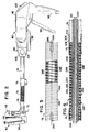
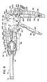
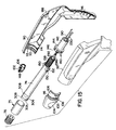
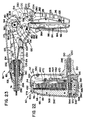
- a surgical stapling instrument generally 50, which includes a distal stapling head assembly 60 connected by a support shaft assembly 70 to a proximal actuator handle assembly 80.
- the stapling head assembly 60 includes a proximal or fixed jaw 62 which supports a staple cartridge 64 and a distal or movable jaw 66 which supports a staple forming anvil 68 ( Figure 2).
- the staple cartridge 64 receives one or more rows of staples 65 ( Figure 17) which are driven against the anvil 68 and formed into a B-shaped configuration to fasten tissue together. For example, nineteen staples are held in the staple cartridge 64 and arranged in two staggered rows.
- the surgical stapling instrument 50 can be adapted to operate with two-part surgical fasteners instead of the staples 65.
- the proximal or fixed jaw 62 is mounted in a hinge-like fashion on a pivot connection 72 which permits the stapling head assembly 60 to pivot about a vertical axis 52 into different angular orientations relative to a centerline or longitudinal axis 54 of the support shaft assembly 70.
- the pivot connection 72 is arranged to allow the stapling head assembly 60 to pivot about the vertical axis 52 in approximately 20° increments.
- the articulated stapling head assembly 60 is pivotable either clockwise or counterclockwise about the vertical axis 52 to positions oriented at about ⁇ 20°, ⁇ 40°, ⁇ 60° and ⁇ 80° relative to the longitudinal axis or centerline 54.
- the support shaft assembly 70 is rotatably mounted on the actuator handle assembly 80 for rotation about the longitudinal axis or centerline 54. Preferably, the support shaft assembly 70 is rotatable over an angular range of approximately 180° or more about the centerline 54.
- a control knob 82 is coupled to the support shaft assembly 70 and rotatably mounted at the distal end of the actuator handle assembly 80 to allow the support shaft assembly 70 to be rotated about its axis 54 to adjust the rotational orientation of the stapling head assembly 60.
- the shaft assembly 70 includes a tubular support shaft 74 rotatably mounted on the actuator handle assembly 80 and secured by a coupling sleeve 75 to a flexible tubular shaft 76.
- the flexible tubular shaft 76 is capable of bending in any radial direction relative to the centerline 54 of the shaft assembly 70 into a bent or curved shape ( Figure 3).
- the hinge-like pivot connection 72 is mounted on a coupling sleeve 78 at the distal end of the flexible shaft 76.
- the tubular support shaft 74 can be made of plastic material.
- the central coupling sleeve 75 and the distal coupling sleeve 78 can be made of metal, e.g., aluminum.
- the actuator handle assembly 80 includes a pivotally mounted closure lever 84 for closing the movable jaw 66 toward the fixed jaw 62 to clamp a tubular section of tissue between the jaws 62 and 66.
- the actuator handle assembly 80 also includes a pivotally mounted firing lever 86 for actuating the stapling head assembly 60 to drive the staples from the staple cartridge 64 through the tissue and to form the staples against the anvil 68.
- the actuator handle assembly 80 includes a pair of hollow handle sections 90 and 92 made of plastic material which can be welded or snap fit together. Each of the handle sections 90 and 92 includes a proximal depending handle grip 96. A manually operable release button 100 protrudes upwardly at the proximal end of the actuator handle assembly 80.
- the control knob 82 comprises a pair of hollow tapered cylindrical half-sections 102 made of plastic material which can be welded or snap fit together.
- Each of the knob half-sections 102 has a recessed finger grip area 104 which facilitates the manual engagement and operation of the control knob 82.
- each knob half-section 102 has a semi-circular proximal flange 106 provided with a resilient finger 108 which projects radially outward from the semi-circular flange 106.
- Each radially projecting finger 108 engages a series of serrations or teeth 110 which are arranged along a semi-circular path adjacent to the distal end of each of the handle sections 90 and 92.
- the resilient fingers 108 and the serrations 110 provide a detent mechanism which defines fourteen angular positions uniformly spaced apart for rotation of the shaft assembly 70.
- the semi-circular flanges 106 form a hub which is rotatably supported by an inwardly projecting semi-circular flange 112 formed at the distal end of each of the handle sections 90 and 92.
- the semi-circular flanges 106 are rotatably supported by a semi-circular rib 114 formed on the interior of each of the handle sections 90 and 92.
- the semi-circular flanges 112 and the semi-circular ribs 114 provide bearing surfaces to facilitate the rotation of the control knob 82.
- a semi-circular ridge 116 formed on the outside of each semi-circular flange 106 is located inside the semi-circular flange 112 at the proximal end of each of the handle sections 90 and 92 to limit the axial displacement of the control knob 82 relative to the handle assembly 80.
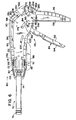
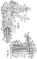
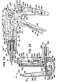
- the actuator handle assembly 80 includes an actuator mechanism, generally 120, contained within the hollow plastic handle sections 90 and 92.
- the actuator mechanism 120 includes a pair of outer support plates 122 which are similar in shape to the handle sections 90 and 92.
- Each of the handle sections 90 and 92 is provided with a set of internal flanges and ribs which support the support plates 122 in a fixed position within the actuator handle assembly 80 when the handle sections 90 and 92 are assembled together.
- the features of the support plates 122 can be integrally formed on the interior of the handle sections 90 and 92.
- the support plates 122 are fastened together in a spaced parallel relationship by a pair of transverse connecting pins 124 located adjacent to the distal ends of the support plates 122 and by a pair of connecting pins 126 extending transversely between a pair of depending grip portions 128 of the support plates 122.
- a double step pivot pin 130 is mounted in a pair of holes 131 formed in the top proximal portions of the support plates 122 and pivotally supports the other components of the actuator mechanism 120.
- the support plates 122 are also joined together by a front connecting pin 132 and a rear connecting pin 134 which pivotally supports the release button 100.
- a pair of opposed semi-circular flanges 136 which extend axially from the distal ends of the support plates 122 are received between the semi-circular flanges 106 of the knob half-sections 102 ( Figure 8).
- the tubular support shaft 74 has a threaded proximal end 138 which is threadably received in an adjusting nut 140 having an elongated tubular body 142 located between the semi-cylindrical flanges 136 of the support plates 122.
- the adjusting nut 140 has an enlarged distal end 144 provided with a series of circumferentially spaced longitudinal grooves 146 which are adapted to receive a pair of opposed longitudinal ribs 148 (one shown) formed on the inside of the knob half-sections 102.
- the tubular support shaft 74 has a pair of diametrically opposed flanges 150 adjacent to its threaded proximal end 138 which are provided with longitudinal grooves 152 for receiving the longitudinal ribs 148 on the inside of the knob half-sections 102.
- the adjusting nut 140 allows the effective length of the support shaft assembly 70 to be adjusted by rotation of the adjusting nut 140 on the threaded proximal end 138 of the tubular support shaft 74 during the assembly of the stapling instrument 50.
- the knob half-sections 102 are assembled together at the proximal end of the tubular support shaft 74.
- the longitudinal ribs 148 which are received in the longitudinal grooves 146 and 152 prevent any relative rotation between the tubular support shaft 74 and the adjusting nut 140 after the assembly of the stapling instrument 50 to maintain the desired shaft length.
- the actuator mechanism 120 includes a pair of closure lever plates 154 each including a pivot hole 156 for receiving the double step pivot pin 130 to pivotally support the closure lever plates 154 for pivotal movement relative to the support plates 122.
- the closure lever plates 154 are maintained in a spaced parallel relationship by the double step pivot pin 130 which rotatably supports a cam pulley 160.
- the closure lever plates 154 include elongated depending lever portions 162 which are contained inside a hollow plastic closure lever shroud 164 ( Figure 6) to provide the jaw closure lever 84 of the actuator handle assembly 80.
- the staple firing lever 86 is pivotally mounted between the closure lever plates 154 by a pair of transverse pivot pins 168 (one shown) extending from its opposite sides and rotatably received in a pair of pivot holes 170 (one shown) formed in the closure lever plates 154.
- the staple firing lever 86 preferably made of molded plastic material, includes a pair of gear sectors 172 which are spaced apart to receive the cam pulley 160 therebetween.
- a pair of firing lever deployment pins 174 extend transversely from the opposite sides of the gear sector 172.
- the firing lever deployment pins 174 are slidably received in a pair of arc-shaped slots 178 formed in the closure lever plates 154.
- Each cam slot 180 includes a lower cam track section 182 and an upper cam track section 184 which intersect at a rear corner 185.
- each firing lever deployment pin 174 has a cylindrical base 175 which is slidably received in the corresponding arc-shaped slot 178 of the closure lever plate 154.
- the outer end of each deployment pin 174 comprises a rectangular block 176 which is slidably received in the corresponding cam slot 180 of the support plate 122.
- On the outer edge of the rectangular block 176 is a diagonal cam 186 which cooperates with a rectangular ledge 188 ( Figure 15) formed on each of the handle sections 90 and 92 to provide a detent mechanism to control the action of the staple firing lever 86.
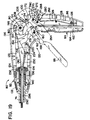
- a staple firing cable 190 is anchored to the cam pulley 160 by a cable crimp member 192 at the proximal end of the firing cable 190.
- the firing cable 190 is made of stainless steel and the cable crimp member 192 is made of stainless steel which is crimped onto the staple firing cable 190.
- the cable crimp member 192 is cylindrical in shape with an axial bore for receiving the staple firing cable 190.
- the cable crimp member 192 is crimped, for example, into a hexagonal cross section.
- the hexagonal cable crimp member 192 is anchored to the cam pulley 160 to apply tension to the firing cable 190 when the cam pulley 160 is rotated.
- the actuator mechanism 120 includes a pair of drive gears 194 which mesh with the gear sectors 172 of the staple firing lever 86.
- the drive gears 194 are positioned on opposite sides of the cam pulley 160 and are rotatable about the pivot pin 130.
- Each of the drive gears 194 has a drive lug 196 for movement into engagement with a pair of side lugs 198 at the top of the cam pulley 160 when the drive gears 194 are rotated.
- the drive gears 194 are free to rotate relative to the cam pulley 160 until the drive lugs 196 on the drive gears 194 engage the side lugs 198 on the cam pulley 160.
- the drive gears 194 and the cam pulley 160 rotate together in a clockwise direction to apply tension to the staple firing cable 190.
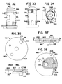
- the cam pulley 160 comprises a pair of disc-shaped side members 200 which are integrally formed with and separated by an interior cam member 202.
- the cam member 202 has a hexagonally shaped passage 204 in which the hexagonal cable crimp member 192 is anchored to secure the firing cable 190 to the cam pulley 160.
- the cam pulley 160 has a first set of teeth 206 formed at the periphery of the disc-shaped side members 200 which engage an anti-backup tang 208 on the release button 100 to hold the cam pulley 160 in position during storage and prior to the firing of the stapling instrument 50.
- the cam pulley 160 has a second set of teeth 209 formed at the periphery of the disc-shaped side members 200 which engage the anti-backup tang 208 after the stapling instrument 50 is fired to control the pay-out of the staple firing cable 190.
- the side lugs 198 extend radially at the periphery of the disc-shaped side members 200 and are aligned with the second set of teeth 209.
- a tubular spring pin 199 is inserted in a pair of holes in the side lugs 198.
- the anti-backup tang 208 can be eliminated from the release button 100 ( Figure 14) and the cam pulley 160 can be formed without the first and second teeth 206 and 209 ( Figure 38) to eliminate the anti-backup feature.
- the drive gears 194 can be formed on the cam pulley 160 to reduce the number of components in the actuator mechanism 120.
- the interior cam member 202 of the cam pulley 160 comprises a contoured cam lobe of varying height for actuating the firing cable 190 with different mechanical advantages as the pulley 160 is rotated.
- the cam lobe 202 includes a first cam region 210 with a large lobe height to provide a small mechanical advantage for actuating the firing cable 190, a second cam region 211 with an intermediate lobe height which provides an increasing mechanical advantage, and a third cam region 212 with a small lobe height which provides a large mechanical advantage.
- the cam region 210 engages the staple firing cable during the initial portion of the stroke of the staple firing lever 86 and the cam region 212 engages the staple firing cable 190 during the final portion of the stroke of the staple firing lever 86.
- the actuator mechanism 120 includes a closure control link 214 comprising a pair of triangularly shaped side members 216 which are joined together in a spaced parallel relationship by an integrally formed bridge pin 218.
- a first pair of pivot pins 220 extend transversely in opposite directions from the lower end of the link 214.
- the outer ends of the pivot pins 220 are slidably received in a pair of inclined guide slots 222 formed in the support plates 122.
- a second pair of pivot pins 224 at the upper end of the link 214 extend transversely in opposite directions from the side members 216.
- the pivot pins 224 are received in a pair of pivot holes 226 formed in a pair of distal fingers 228 on the closure lever plates 154.
- a jaw closure cable 230 is looped over the bridge pin 218 ( Figure 10) between the side members 216 of the closure control link 214.
- the closure control link 214 pivots clockwise while the pivot pins 220 slide rearwardly in the guide slots 222 to apply tension to the jaw closure cable 230 when the closure lever plates 154 are actuated by the jaw closure lever 84.
- At the base of each pivot pin 222 is a raised bearing surface 225 which slides along the inside of the corresponding support plate 122 when the control link 214 is pivoted by the jaw closure plates 154.
- the staple firing cable 190 and the jaw closure cable 230 extend through a stop plate 232 located adjacent to the distal end of the support shaft assembly 70.
- a hollow cylindrical body 234 at the distal end of the stop plate 232 extends into the proximal end of the tubular body 142 of the adjusting nut 140.
- a pair of bearing surfaces 235 is formed on the distal side of the stop plate 232 for engaging the semi-circular flanges 106 which form the hub of the control knob 82.
- the stop plate 232 has a central rectangular slot 236 for receiving the firing cable 190 and the closure cable 230.
- the stop plate 232 includes a pair of tabs 238 projecting laterally from its opposite sides which are received in a pair of mounting holes 240 ( Figure 14) formed in the support plates 122.
- the release button 100 comprises a hollow molded plastic body including a pair of depending flanges 250 on its opposite sides each including a pivot hole 252 for receiving the connecting pin 134 to pivotally mount the release button 100 on the support plates 122.
- the release button 100 also has a depending rear finger 254 provided with a laterally projecting tab 256 which cooperates with a cylindrical female connector 258 ( Figure 10) on the inside of one of the handle sections 90 and 92 to limit the outward pivotal movement of the release button 100 relative to the actuator handle assembly 80.
- Pivotally mounted underneath the release button 100 is a release lever 260 which is normally urged by a release spring 262 into engagement with the depending finger 254 of the release button 100.
- the release lever 260 has a lower pair of pivot pins 264 (one shown) extending transversely in opposite directions therefrom which are received in a pair of pivot holes 266 formed in the support plates 122. As shown in Figure 6, the pivot holes 266 are enlarged so that the pivot pins 264 are free to slide and pivot relative to the support plates 122.
- the release lever 260 has a latch arm 268 provided with an upper pair of guide pins 270 extending transversely in opposite directions therefrom which are received in a pair of guide slots 272 formed in the support plates 122.
- a cam 274 on the underside of the release lever 260 is engaged by the release spring 262 to urge the release lever 260 into engagement with the depending finger 254 of the release button 100.
- the release spring 262 comprises an elongated flat metal strip which is curled at its opposite ends to form a pair of hollow cylindrical flanges 276 and 278.
- the lower cylindrical flange 276 is mounted on the lower connecting pin 126.
- the release spring is flexed about the upper connecting pin 126 and the upper cylindrical flange 278 engages the cam 274 on the release lever 260.
- the release spring 262 provides a biasing force which urges the release lever 260 against the depending finger 254 to bias the release button 100 in a counterclockwise direction about the pivot pin 134.
- each of the closure lever plates 154 has a proximally extending latch lug 280 located adjacent to the release lever 260.
- the jaw closure lever 84 When the jaw closure lever 84 is actuated to pivot the closure lever plates 154 about the pivot pin 130 ( Figure 17), the latch lugs 280 engage the arm 268 and pivot the closure lever 260 clockwise against the bias of the release spring 262.
- the jaw closure lever 84 When the jaw closure lever 84 is moved to its fully closed position ( Figure 19), the release lever 260 is biased counter-clockwise by the release spring 262 to move the latch arm 268 underneath the latch lugs 280 to latch the jaw closure lever 84 in its fully closed position.
- the lugs 280 cam against the release lever 260 and the release spring 262 tends to resist the pivotal movement of the closure lever plates 154 relative to the support plates 122 when the jaw closure lever 84 is moved toward its closed position.
- the camming action of the lugs 280 and the release lever 260 prevents rattling of the actuator mechanism 120 and assists in holding the jaw closure lever 84 in its open position.
- the flexible tubular support shaft 76 comprises a dual helical coil structure comprising a first elongated helical member 282 and a second elongated helical member 284 which are concentrically wound together with the coils 286 of the first helical member 282 alternately interspersed with the coils 288 of the second helical member 284.
- each coil 286 of the helical member 282 has a round cross section.
- Each coil 288 of the helical member 284 has a triangular, wedge-shaped cross section defining a pair of inwardly sloped surfaces 290 which engage the round exterior surfaces of the adjacent round coils 286.
- the wedge-shaped coils 288 are positioned between the round coils 286 to maintain a desired separation between the adjacent round coils 286 and to maintain the first helical member 282 in tension.
- Inside the helical coil members 282 and 284 is a concentrically mounted cable support tube 292, preferably made of a malleable metal such as aluminum, which allows the flexible shaft 76 to assume its bent or curved shape.
- the cable support tube 292 is flexible in any radial direction relative to the longitudinal axis or centerline 54 of the support shaft assembly 70. The cable support tube 292 enables the flexible support shaft 76 to assume its curved configuration and to resist tension from the cables 190 and 230 when the stapling head assembly 60 is actuated.
- the flexible support shaft 76 is adapted to be bent within a predetermined range, e.g., up to about ⁇ 30° in any direction from its straight configuration. After bending, the flexible support shaft 76 maintains its bent shape ( Figure 3) until the shaft 76 is further manipulated.
- the malleable cable support tube 292 ( Figure 4) prevents the bent support shaft 76 from inadvertently straightening. This shape retention feature permits access of the stapling head assembly 60 into the pelvic cavity while avoiding contact of the actuator handle assembly 80 with the viscera or body wall.
- the helical coil members 282 and 284 provide a geometry such that the axis of the shaft assembly 70 remains a substantially constant length during the bending of the flexible support shaft 76.
- twin helical coil construction also provides a solid load path which resists the compressive forces during closure and firing while avoiding any tendency for the flexible support shaft 76 to return to the straight condition.
- the geometry of the circular coils 286 and the triangular coils 288 is such that, at a bending angle of about 30°, one or the other of the coils becomes solid, i.e., either the adjacent round coils 286 engage each other or the adjacent triangular coils 288 engage each other.
- This condition causes a sharp increase in the force required to bend the flexible support shaft 76 and provides a limit on the extent of the bending motion.
- This limitation on the angle of bend keeps the cable friction forces low so that the system operates in the regime of substantially constant axis length.
- the malleable cable support tube 292 is free to slide axially within the helical members 282 and 284 so that any change in the length of the cable support tube 292 due to plastic deformation does not effect the force required to bend the flexible support shaft 76.
- the wedge-shaped coils 288 are reduced in width compared with the diameter of the round coils 286. Also, the wedge-shaped coils 288 are shaped to allow the adjacent round coils 286 on the inside of the bend to engage each other when the flexible support shaft 76 is bent to about a 30° bending angle.
- the helical coil spring member 282 and the helical wrap wire member 284 are coiled together along a common longitudinal axis 285 with the round coils 286 alternating with the triangular or wedge-shaped coils 288 and the coil spring member 282 in tension.
- the wrap wire member 284 is wrapped about the coil spring member 282 with the wedge-shaped coils 288 positioned between the round coils 286 to maintain a desired separation between the adjacent round coils 286 when the support shaft assembly 76 is straight.
- the wedge-shaped coils 288 are forced between the adjacent round coils 286 to maintain the coil spring member 282 in tension.
- the coil spring members 282 and 284 are secured together, e.g., by welding at linear weld areas 294 adjacent to the opposite ends of the flexible support shaft 76.
- the details of the flexible support shaft 76, the coil spring member 282, the wrap wire member 284, the round coils 286 and the wedge-shaped coils 288 are described in a co-pending U. S. Patent Application entitled "Flexible Support Shaft Assembly", which was filed on December 6, 1993 and assigned to the same assignee, Ethicon, Inc., as the present application. This prior co-pending application is herein incorporated by reference.
- each of the wedge-shaped coils 288 initially separates the adjacent round coils 286 longitudinally from each other when the flexible support shaft 76 is straight.
- the round coils 286 and the wedge-shaped coils 288 are aligned along the common longitudinal axis 285.
- the wedge-shaped coils 288 are slidable relative to the round coils 286 to allow the flexible support shaft 76 to bend in a transverse direction relative to its longitudinal axis 285.
- the sliding action of the wedge-shaped coils 288 allows the flexible support shaft 76 to bend until the round coils 286 on the inside of the bend engage each other and limit the bending of the flexible support shaft 76.
- the wedge-shaped coils 288 are shifted laterally relative to the adjacent round coils 286.
- the longitudinal axis 289 of the wedge-shaped coils 288 is shifted slightly relative to the longitudinal axis 285 of the round coils 286 in the direction of the bending of the flexible support shaft 76.
- the portions of the round coils 286 on the inside of the bend move closer together while the portions of the round coils 286 on the outside of the bend move farther apart.
- the flexible support shaft 76 is bent into a curved configuration.
- the bending of the flexible support shaft 76 occurs without any substantial change in the overall length of the flexible support shaft assembly 76 and without stretching of the coil spring member 282 along its axis 285 until the round coils 286 on the inside of the bend move into engagement with each other. Up to this point, the bending of the flexible support shaft 76 can be accomplished by applying a relatively small bending force to the coil spring member 282 and the wrap wire member 284.
- any additional bending of the flexible support shaft 76 requires the stretching of the coil spring member 282 to move the portions of the round coils 286 on the outside of the bend farther apart.
- the point at which the round coils 286 on the inside of the bend move into engagement with each other defines a limit on the bending of the support shaft 76 in the transverse direction.
- a double lumen cable support member 296 is mounted inside the cable support tube 292.
- the cable support member 296 extends from the cylindrical body 234 ( Figure 10) of the stop plate 232 to the pivot connection 72 ( Figure 11).
- the cable support member 296 includes an upper section 298 provided with a longitudinal passageway 300 for receiving the staple firing cable 190 and a lower section 302 provided with a longitudinal passageway 304 for receiving the closure cable 230.
- the lower section 302 has a half-round configuration and the upper section 298 is reduced in width compared with the lower section 302 to define a key-shaped cross section.
- the stop plate 232 has a key-hole passage 242 ( Figure 43) in its cylindrical body 234 for receiving the key-shaped proximal end of the cable support member 296.
- the tubular support shaft 74 is secured to the flexible support shaft 76 by the coupling sleeve 75 which is preferably made of a deformable material, e.g., aluminum.
- the distal end of the tubular support shaft 74 has a series of annular grooves 306 of reduced diameter which provide a series of longitudinally spaced annular ridges 308.
- the coupling sleeve 75 is deformed, e.g., by magneforming, into contact with the helical coils 286 and 288 and with the annular grooves 306 and annular ridges 308 to secure the coupling sleeve 75 to the tubular support shaft 74 and the flexible support shaft 76.
- the distal ridge 308 has a pair of flat surfaces 305 ( Figure 15) on its opposite sides to prevent rotation of the tubular support shaft 74 relative to the coupling sleeve 75.
- the pivot connection 72 which pivotally mounts the stapling head assembly 60 on the shaft assembly 70 comprises a knuckle housing 310 which is mounted on the flexible tubular support shaft 76 by the coupling sleeve 78.
- the distal end of the flexible support shaft 76 is received in the distal coupling sleeve 78 which is secured, e.g., by magneforming, to the flexible support shaft 76.
- the knuckle housing 310 includes a pair of hollow, cylindrically shaped hinge arms 312 and 314 ( Figure 16) which receive a cylindrical knuckle pin 316 for rotation in a hinge-like fashion.
- a distally projecting flange 318 is formed at the bottom of the knuckle pin 316.
- a passage 320 ( Figure 33) extends radially through the knuckle pin 316 for slidably receiving the closure cable 230.
- the knuckle housing 310 and the knuckle pin 316 are preferably made of plastic material.
- the knuckle housing 310 includes a hollow cylindrical body 322 projecting distally therefrom and received in the coupling sleeve 78 which is preferably made of aluminum.
- the cylindrical body 322 has an annular groove 324 on its outer surface which provides a pair of longitudinally spaced annular ridges 326.
- the coupling sleeve 78 is deformed, e.g., by magneforming, into contact with the annular groove 324 and annular ridges 326 and with the helical coils 286 and 288 to secure the knuckle housing 310 to the flexible support shaft 76.
- the proximal ridge 326 has a pair of flat surfaces 315 (Figure 16) on its opposite sides to prevent rotation of the knuckle housing 310 relative to the flexible support shaft 76.
- the cylindrical body 322 has a longitudinal key-hole passage 325 ( Figure 42) for receiving the distal key-shaped end of the cable support member 296.
- the fixed jaw 62 includes a head plate 328, preferably made of metal, e.g., stainless steel, which is adapted to receive and support the staple cartridge 64.
- the head plate 328 ( Figure 16) is formed as a double-walled, generally rectangular member with a pair of opposed vertical side walls 330 which are mirror images of each other.
- the staple cartridge 64 preferably made of plastic material, has a narrow rectangular configuration and is mounted at the front of the head plate 328 between the side walls 330.
- the head plate 328 is pivotally supported by the knuckle housing 310 and the knuckle pin 316.
- the side walls 330 are joined together by an upper flange 332 which is curved and slidably received in an arcuate channel 334 ( Figure 11) formed at the top of the knuckle housing 310.
- the side walls 330 are also joined together by a lower flange 336 which is curved and rotatably received behind the knuckle pin 316 between the hinge arms 312 and 314.
- the head plate 328 is attached to the knuckle housing 310 in a hinge-like manner to pivotally support the stapling head assembly 60 at the distal end of the support shaft assembly 70.
- the side walls 330 of the head plate 328 include a pair of distally projecting side plates 338 which are spaced apart and provided with holes 340 for receiving a bearing pin 342.
- the lower flange 318 on the knuckle pin 316 is received between the side plates 338.
- the knuckle pin 316 has a set of detents 344 at its lower end which cooperate with a series of circumferentially spaced notches 346 formed on the interior of the lower hinge arm 314 to provide a detent mechanism for controlling the pivotal movement of the knuckle pin 316 relative to the knuckle housing 310.
- the six detents 344 cooperate with eighteen notches 346 ( Figure 42) which are uniformly spaced apart by 20° on the inside of the lower hinge arm 314.
- the detents 344 on the knuckle pin 316 engage the notches 346 on the interior of the lower hinge arm 314 to define 20° intervals for the pivotal movement of the stapling head assembly 60 about the vertical axis 52.
- the detents 334 and notches 346 allow the stapling head assembly 60 to pivot over a range of about ⁇ 80° relative to the longitudinal axis 54.
- the knuckle housing 310 is provided with an upwardly curved cable passage 350 for receiving the firing cable 190.
- the curved passage 350 in the knuckle housing 310 allows the firing cable 190 to turn smoothly at right angles as it passes through the knuckle housing 310.
- the top of the knuckle pin 316 has a conical surface 352 ( Figure 32) which extends circumferentially about the knuckle pin 316 and provides a clearance for the firing cable 190 and allows the knuckle pin 316 to rotate about its axis without interference with the firing cable 190.
- the cable passage 320 in the knuckle pin 316 is oval in shape for receiving the closure cable 230.
- the cable passage 320 has opposite inner walls 354 (Figure 34) which curve outwardly in the proximal direction so that the cable passage 320 terminates at a rearwardly facing slot 356 ( Figures 32-33) on the proximal side of the knuckle pin 316.
- the oppositely curved walls 354 of the passage 320 provide a path of substantially constant length for the closure cable 230 as the knuckle pin 316 is rotated relative to the knuckle housing 310. This constant length feature tends to prevent changes in the tension on the closure cable 230 and changes in the gap between the staple cartridge 64 and the anvil 68 when the stapling head assembly 60 is rotated about the vertical axis 52 relative to the support shaft 70.
- the movable jaw 66 comprises a generally L-shaped anvil shroud 360, preferably made of molded plastic material, including a pair of elongated vertical flanges 362 extending upwardly from a pair of side plates 364.
- a cam actuator finger 366 projects upwardly at the rear of each side plate 364.
- the staple forming anvil 68 comprises a generally L-shaped member, preferably made of metal, e.g., aluminum, including an elongated upstanding distal arm 368 which projects upwardly from a rectangular base member 370.
- the distal arm 368 of the anvil 68 is received between and secured to the vertical flanges 362 by a pair of spring pins 372.
- the anvil 68 has a pair of elongated flanges 374 extending along the opposite sides of its arm 368 which engage the vertical flanges 362 of the anvil shroud 360.
- the proximal edges of the elongated flanges 374 serve as cutting guides for a surgical knife or scalpel.
- a depending curved finger 376 is formed at the proximal end of the base member 370 and is received in a corresponding notch 378 formed at the bottom of the anvil shroud 360.
- the movable jaw 66 is slidably and pivotally mounted on the fixed jaw 62 in the following manner.
- a slide pin 380 is slidably received in an elongated horizontal slot 382 formed in the base member 370 of the anvil 68.
- the opposite ends of the slide pins 380 are slidably received in a pair of elongated horizontal slots 384 formed in the side plates 338 of the head plate 328.
- the slide pin 380 which is slidable within the slots 382 and 384 pivotally supports the base member 370 of the anvil 68 on the head plate 328 and allows the movable jaw 66 to slide and pivot into a closed position relative to the fixed jaw 62.
- the outer ends of the bearing pin 342 are inserted into the holes 340 of the side plates 338.
- the bearing pin 342 is slidably received in an elongated guide slot 386 formed in the base member 370 of the anvil 68.
- the guide slot 386 includes a longitudinal section 388 and an upwardly inclined section 390 ( Figure 11). The bearing pin 342 and the guide slot 386 guide the movable jaw 66 into an upright position adjacent to the fixed jaw 62 when the stapling head assembly 60 is closed.
- a closure cable passageway 392 extends longitudinally through the base member 370 of the anvil 68.
- the closure cable 230 comprises a continuous flexible belt with loops at its opposite ends.
- the closure cable 230 extends into the passageway 392 and is looped over a closure cable pin 394 inserted in a pair of holes 395 (one shown) extending into the opposite sides of the base member 370 and intersecting the cable passageway 392.
- the bearing pin 342 is retained in the holes 340 and the slide pin 380 is retained in the slots 384 of the side plates 338 by the side plates 364 of the anvil shroud 360.
- the closure cable 230 extends through a compression return spring 396 which extends into the cable passageway 392.
- the compression return spring 396 is engaged with the base member 370 inside the passageway 392 and with the staple cartridge 64 to normally bias the movable jaw 66 to the open position.
- a passage 398 extends longitudinally through the tip of the anvil 68 on the movable jaw 66.
- a retractable tissue retaining pin 400 mounted on the fixed jaw 62 is extended through a passage 402 in the staple cartridge 64 into the passage 398 when the movable jaw 66 is closed.
- the tissue retaining pin 400 comprises an elongated cylindrical member, preferably made of metal, e.g., stainless steel, with a rounded or pointed distal end 404.
- the tissue retaining pin 400 is pivotally attached to an elongated U-shaped wire spring 405 ( Figure 16) which extends through a pivot hole at the proximal end of the pin 400.
- the spring 405 has a pair of cantilever spring arms 406 which span the staple cartridge 64.
- the spring arms 406 terminate in a pair of vertical members 408 which are inserted into a pair of slots 410 formed on opposite sides of the staple cartridge 64.
- One of the vertical spring members 408 has a curved end 412 which is inserted into a curved slot 414 on one side of the staple cartridge 64.
- a pair of pin placement arms 416 is pivotally mounted on a pair of laterally projecting pivot pins 418 on opposite sides of the staple cartridge 64.
- the pin placement arms 416 are positioned to engage the cantilever spring arms 406 of the tissue retainer spring 405.
- Each pin placement arm 416 includes a wedge-shaped cam 420 which projects laterally outward from a window 422 formed in each of the side walls 330 of the head plate 328.
- the cam actuator fingers 366 engage the cams 420 to pivot the pin placement arms 416 counter-clockwise, as viewed in Figure 9, to advance the tissue retaining pin 400 from the fixed jaw member 62 into the passage 398 formed at the tip of the anvil 68 to capture the tissue between the anvil 68 and the staple cartridge 64.
- the cantilever spring arms 406 retract the tissue retaining pin 400 into the fixed jaw member 62.
- the compression spring 396 returns the movable jaw member 66 to its open position.
- a hollow plastic cover 424 is fitted over the top portions of the side walls 330 of the head plate 328.
- the cover 424 has a pair of forwardly projecting side flaps 426 which provide an earmuff-like shield over the top portions of the side plates 330.
- Each of the side flaps 426 includes a pair of internal ribs (not shown) which are received in a pair of longitudinal slots 428 formed in each of the side plates 330 to fasten the cover 424 on the head plate 328.
- the cover 424 also includes a depending proximal arm 430 provided with a tab 432 at its lower end which is received inside the upper curved flange 332 of the head plate 328.
- the staple cartridge 64 comprises an elongated, generally rectangular housing 440, preferably made of plastic, which is received between the side plates 330 of the head plate 328.
- a pair of fastener pins 442 projecting laterally from opposite sides at the top of the staple cartridge 64 are received in a pair of vertical slots 444 formed in the side walls 330 of the head plate 328.
- the staple cartridge 64 is secured to the side walls 330 by a rivet 446 which extends transversely through the depending leg 448 at the bottom of the staple cartridge 64.
- a pair of cylindrical locator pins 450 on opposite sides of the staple cartridge 64 is received in a pair of openings 452 formed in the side walls 330 of the head plate 328.
- the depending leg 448 has a curved bearing surface 454 for engaging the cylindrical knuckle pin 316. Also, a horizontal flange 356 at the base of the depending leg 448 is received in a notch 458 ( Figure 32) formed at the front of the cylindrical knuckle pin 316.
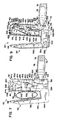
- a staple driver 460 is slidably mounted in the staple cartridge 64 for driving the staples 65 against the anvil 68.
- the staple driver 460 is preferably made of plastic material and includes an insert 462 made of metal, e.g., stainless steel, which reinforces the plastic staple driver 460 to resist the forces encountered when the staples 65 are formed.
- the staple driver 460 is actuated by a slidable firing cam 464 made of metal, e.g., stainless steel, which is slidably mounted on the fixed jaw 62 and engaged with the staple driver insert 462.
- the firing cam 464 includes a proximal offset section 466 provided with a longitudinal bore in which the firing cable 190 is inserted.
- a cable crimp member 468 which is hexagonal in shape is secured to the distal end of the firing cable 190 to actuate the firing cam 464 when the firing cable 190 is pulled in the proximal direction.
- the firing cam 464 forms part of a dual cam actuator mechanism for actuating the staple driver 460 with different mechanical advantages when the staple firing trigger 86 is actuated.
- the dual cam actuator mechanism is adapted to actuate the staple driver 460 with a first mechanical advantage over a first portion of the stroke of the staple firing trigger 86 and with a second mechanical advantage over a second portion of the stroke of the staple firing trigger 86.
- the firing cam 464 includes a pair of laterally projecting pins 470 on each of its sides which are slidably received in a pair of inclined cam slots 472 formed in each of the side walls 330 of the head plate 328.
- the pins 470 and cam slots 472 provide a first portion of the dual cam mechanism for actuating the staple driver 460.
- Each cam slot 472 is inclined downwardly toward the front of the head plate 328, e.g., at an angle of 15° from the vertical axis 52 ( Figure 1).
- the pins 470 ride along the inclined slots 472 so that the firing cam 464 and the staple driver 460 are displaced in the distal direction.
- Each of the cam slots 472 terminates in a bottom portion 474 which is angled slightly backward on the head plate 328 to reduce the load encountered in the over-travel operation which is described below.
- the firing cam 464 is contoured at its distal edge to provide a pair of inclined cam actuator surfaces 476 which slidably engage a complementary pair of inclined cam follower surfaces 478 formed at the proximal edge of the staple driver insert 462.
- the cam actuator surfaces 476 and the cam follower surfaces 478 provide a second portion of the dual cam mechanism for actuating the staple driver 460.
- both pairs of inclined cam surfaces 476 and 478 are inclined at an angle of 15° from the vertical axis 52.
- Each inclined cam actuator surface 476 on the firing cam 464 terminates in a flat cam actuator surface 480 oriented parallel to the vertical axis 52.
- each inclined cam follower surface 478 on the staple driver 460 terminates in a flat cam follower surface 482 oriented parallel to the vertical axis 52.
- the inclined cam surfaces 476 on the firing cam 464 ride along the inclined cam surfaces 478 on the staple driver insert 462 to push the staple driver 460 distally relative to the firing cam 464.
- the flat cam surfaces 480 on the firing cam 464 are arranged to engage the flat cam surfaces 482 on the staple driver insert 462 before the pins 470 on the firing cam 464 arrive at the bottom vertical portions 474 of the inclined slots 472.
- the dual cam mechanism of the stapling head assembly 60 occupies less space than the staple firing mechanisms of the prior art. Thus, the outer dimensions of the fixed jaw 62 which houses the dual cam mechanism are minimized to allow the stapling head assembly 60 to access restricted surgical sites, e.g., in the pelvic area.
- the surgical stapling instrument 50 is operated in the following manner. With the jaws 62 and 66 open, the stapling head assembly 60 is articulated about the vertical axis 52 to a desired angular position relative to the longitudinal axis 54.
- the flexible tubular shaft 76 is bent into a curved configuration to conform to the anatomy of the patient.
- the shaft assembly 70 can be rotated about its longitudinal axis 54 to orient the actuator handle assembly 80 in a comfortable position for actuation by the surgeon.
- the stapling head assembly 60 is positioned inside the body and a tissue lumen 55 (Figure 7) to be stapled is located between the open stapler jaws 62 and 66.
- the movable jaw 66 is partially closed by actuating the jaw closure lever 84 with one hand.
- the tissue retaining pin 400 is advanced from the fixed jaw 62 into engagement with the movable jaw 66 to capture the lumen 55 ( Figure 18) between the jaws 62 and 66.
- the other hand is used to guide the stapling head assembly 60 into the desired position.
- the stapling head assembly 60 can be moved along the captured lumen 55 to the desired stapling position. If desired, the jaw closure lever 84 can be returned to its inoperative position to return the movable jaw 66 to its fully open position and to retract the tissue retaining pin 400 into the fixed jaw 62 to allow the stapling instrument 50 to be withdrawn from the body cavity for adjustment of the articulation of the stapling head assembly 60 and the curvature of the flexible tubular shaft 76.
- the jaw closure lever 84 When the stapling head assembly 60 is located in the desired stapling position on the lumen 55, the jaw closure lever 84 is moved to its fully clamped position ( Figure 19) to completely close the jaw 66 to clamp the lumen 55 between the staple cartridge 64 and the anvil 68.
- the firing trigger 86 is grasped and squeezed to fire the staples 65 in the staple cartridge 64.
- the staples 65 are advanced into engagement with the anvil 68 and are formed into a B-shaped configuration to staple the tissue lumen 55 together.
- the lumen 55 is transected by using right angle scissors or by running a scalpel along the cutting guides formed by the longitudinal flanges 374 at the edges of the staple cartridge 64 or the anvil 68.
- the jaws 62 and 66 are unclamped from the lumen 55 by squeezing both levers 84 and 86 toward the handle grip 96 and depressing the release button 100 to actuate the release lever 260 to unlatch the jaw closure lever 84. With the jaws 62 and 64 unclamped and the tissue retaining pin 400 retracted, the stapling instrument 50 is removed from the body cavity.
- the staple firing lever 86 is located at an open and unfired position adjacent to the body of the actuator handle assembly 80.
- the drive gears 194 are oriented with the drive lugs 196 rotated in a counter-clockwise direction away from the side lugs 198 on the pulley 160.
- the detents 206 on the pulley 160 are engaged by the anti-backup tang 208 on the release button 100 to stop the rotation of the pulley 160 in a first position and prevent the pay-out of the firing cable 190 before the staple firing lever 86 is actuated.
- the pulley 160 is held against counter-clockwise rotation by the anti-backup tang 208 and a slight tension is maintained in the firing cable 190. Also, at the initial position of the pulley 160, the firing cable 190 is engaged by the first cam lobe region 210 ( Figure 38).
- each firing lever guide pin 174 travels rearward along the lower cam track section 182 of the cam slot 180 and causes the firing lever 86 to rotate in a counter-clockwise direction about the pivot pins 168 and downward relative to the body of the actuator handle assembly 80 into a ready to fire position.
- the pivotal motion of the firing lever 86 and the jaw closure lever 84 causes the drive gears 194 to rotate clockwise to advance the drive lugs 196 into engagement with the side lugs 198 on the pulley 160.
- the jaw closure lever 84 is moved to a partially closed position ( Figure 17) in which the staple firing lever 86 is pivoted slightly downward from the body of the actuator handle assembly 80. Also, the movement of the jaw closure 84 to the detent position causes the control link 214 to slide and pivot on the pivot pins 220 which travel rearwardly along the guide slots 222. The control link 214 applies tension to the closure cable 230 to pull the distal jaw 66 into an upright, partially closed position ( Figure 18).
- each of the latch lugs 280 on the closure lever plates 154 pushes against the latch arm 268 on the release lever 260 which pivots in a clockwise direction about its pivot pins 264 to allow the latch lugs 280 to move above the release lever 260.
- the guide pins 270 at the top of the arm 268 slide along the guide slots 272 to permit the pivotal movement of the release lever 260.
- the cam fingers 366 engage the corresponding cams 420 and pivot the pin placement arms 416 counter-clockwise, as viewed in Figure 9, about the pivot pins 418.
- the pin placement arms 416 bend the cantilever spring arms 406 forward to extend the tip portion 404 of the tissue retaining pin 400 through the passage 402 at the top of the staple cartridge 64 and into the passage 398 at the top of the anvil 68.
- the bearing pin 342 is positioned at the juncture between the longitudinal portion 388 and the inclined portion 390 of the guide slot 386 and the movable jaw 66 is upright.
- the bearing pin 342 is slidably received in the longitudinal portion 388 of the guide slot 386 to allow the anvil base 370 to slide longitudinally relative to the fixed jaw 62.
- the jaw closure lever 84 is moved to its fully closed position adjacent to the depending handle grips 96 of the actuator handle assembly 80.
- the closure control link 214 is pivoted in a counter-clockwise direction and the pins 220 travel rearwardly along the guide slots 222.
- the tip of the anvil 68 moves into engagement with a tissue stop 492 at the top of the staple cartridge 64.
- the movable jaw 66 pivots slightly about the tissue stop 492 until the bearing pin 342 is engaged by the distal ends of the guide slot 386 ( Figure 20). This bottoming out point occurs before the jaw closure lever 84 reaches the end of its travel.
- the high mechanical advantage of the over-center control link 214 stretches the closure cable 230 and applies a high force, approximately 200 pounds, to pre-load the stapling jaw assembly 60 into the closed position. This high pre-load force helps to resist the staple forming forces encountered during the firing of the staples 65 in the staple cartridge 64.
- the staple firing lever 86 is deployed from an inoperative position ( Figure 10) underneath the body of the actuator handle assembly 80 into an intermediate firing position ( Figure 19) so that the staple firing lever 86 can be grasped by the surgeon for firing of the stapling instrument 50.
- the pivot axis for the staple firing lever 86 is provided by the pivot pins 168 which are received in the pivot holes 170 formed in the closure lever plates 154.
- the staple firing lever 86 is carried backward with the jaw closure lever 84 and the deployment pins 174 travel along the cam slots 180 formed in the support plates 122.
- each of the deployment pins 174 moves along the upwardly and rearwardly curved cam track section 182 of the corresponding cam slot 180. Also, the deployment pins 174 travel partially along the arc-shaped slots 178 in the closure lever plates 154. The movement of each deployment pin 174 along the corresponding lower cam track section 182 forces the staple firing lever 86 to rotate about the pivot pin 168 and deploys the staple firing lever 86 in its firing position at an angle of about 45° from its horizontal start position. As the staple firing lever 86 is deployed in its firing position, the gear sectors 172 on the staple firing lever 86 rotate the drive gears 194 in a clockwise direction to advance the drive lugs 196 toward the side lugs 198 on the pulley 160. As long as each deployment pin 174 is located in the corresponding inclined cam track section 182, the movement of the jaw closure lever 84 can be reversed to return the staple firing lever 86 to its substantially horizontal position.
- the movement of the staple firing lever 86 relative to the jaw closure plates 154 is restricted by the deployment pins 174 which are confined in the lower cam track sections 182.
- any manual pulling force applied to the staple firing lever 86 during its deployment merely urges the jaw closure lever 84 toward its closed position. Since the deployment pins 174 are confined in the lower cam track sections 182, the staple firing lever 86 cannot be actuated to fire the staples in the staple cartridge 64.
- each of the pivot pins 220 is located at the proximal end of the corresponding guide slot 222 and each of the deployment pins 174 is located at a rear corner 185 of the corresponding cam slot 180 where the curved cam track sections 182 and 184 intersect.
- the arc-shaped slot 178 of each jaw closure plate 154 is aligned with the upper curved cam track section 184 of the corresponding cam slot 180 and the staple firing lever 86 is free to pivot relative to the jaw closure lever 84 to actuate the stapling head assembly 60.
- the release lever 260 is biased in a counter-clockwise direction by the release spring 262 to move the latch arm 268 underneath the lugs 280 of the jaw closure plates 154 to latch the jaw closure arm 84 in the closed position.
- the staple firing lever 86 is grasped and pulled toward the jaw closure lever 84.
- the staple firing lever 86 is pivoted about the pivot pins 168 in a counter-clockwise direction toward its fired position ( Figure 21).
- the arc-shaped slots 178 in the jaw closure plates 154 are aligned with the upper curved cam track sections 184 of the cam slots 180 in the support plates 122.
- the deployment pins 174 are free to travel along the upper curved cam track sections 184 to allow the staple firing lever 86 to pivot to its fired position to actuate the stapling head assembly 60. Also, when the staple firing lever 86 is moved to its fired position, the deployment pins 174 travel to the upper distal ends of the arc-shaped slots 178.
- the drive gears 194 are rotated in a counter-clockwise direction by the gear sectors 172.
- the drive lugs 196 engage the side lugs 198 and rotate the pulley 160 in a counter-clockwise direction to apply tension to the firing cable 190 to actuate the firing cam 464 in the stapling head assembly 60.
- the firing of the staples in the staple cartridge 64 is explained in more detail below.
- the stapling head assembly 60 is re-opened after the firing of the staples 65 by squeezing the staple firing lever 86 and the jaw closure lever 84 toward the depending handle grips 96 and depressing the release button 100 to pivot the release lever arm 260 in a clockwise direction about the pivot pins 264.
- the jaw closure plates 154 are pivoted counter-clockwise to an over-travel position ( Figure 23) to raise the latch lugs 280 slightly relative to the latch arm 268 to allow the release lever 260 to be pivoted clockwise by contact with the rear finger 254 of the release button 100.
- each of the control link pivot pins 220 slides forward in the corresponding guide slot 222 and the control link 214 pivots in a clockwise direction to pivot each closure lever plate 154 clockwise about the pivot pin 130 to return the jaw closure lever 84 to its open position ( Figure 24).
- the staple firing lever 86 remains in a fired position adjacent to the jaw closure lever 84 when the stapling head assembly is opened.
- the deployment pins 174 remain in the upper curved cam track sections 184 to prevent the staple firing lever 86 from returning to its horizontal start position.
- the control link 214 is returned to its initial position and each pivot pin 220 is returned to the distal end of the corresponding guide slot 222.
- the staple firing lever 86 is held against the jaw closure lever 84 and the firing lever guide pin 174 remains in the upper cam track 184 of the firing lever guide slot 180.
- the pulley 160 rotates in a clockwise or firing direction to increase the tension in the firing cable 190.
- the tension in the firing cable 190 causes the firing lever 86 to separate slightly from the jaw closure lever 84.
- the separation of the staple firing lever 86 from the jaw closure lever 84 allows the pulley 160 to rotate slightly in a counter-clockwise direction to pay out the firing cable 190.
- the tension in the firing cable 190 decreases to allow the jaw closure lever 84 to freely return to its open position.
- the pulley 160 is rotated in the counter-clockwise direction until the anti-backup tang 208 engages the detents 206 to stop the rotation of the pulley 160 so that the tension in the firing cable 190 no longer tends to further open the firing lever 86.
- the motion of the firing lever guide pin 174 is restricted by the upper cam track 184 of the firing lever guide slot 180 to prevent the firing lever 86 from returning to its original position adjacent to the body of the actuator handle assembly 80.
- the firing cam 464 is pulled downwardly by the firing cable 190 and the staple driver 460 is advanced by two cam mechanisms.
- the firing cam pins 470 travel in the firing cam slots 472 which are inclined downwardly and forwardly at an angle of 15° relative to the vertical axis 52.
- This dual cam mechanism achieves a high mechanical advantage in a compact space.
- the geometry of the two cam mechanisms is such that the firing cam 464 and the staple driver insert 462 move into engagement at the flat cam surfaces 482 and 480 before the travel of the firing cam pins 470 in the firing cam slots 472 is completed.
- This arrangement allows the staple driving mechanism to operate with two mechanical advantages, i.e, a low mechanical advantage during the initial stroke when both cam mechanisms are engaged and a high mechanical advantage toward the end of the stroke when only the firing cam slots 472 are engaged.
- the changeover in the operation of the dual cam mechanisms occurs at a low point in the forming force/deflection curve for the staples. This operation effectively minimizes the firing cable force at all points in the firing stroke of the staple forming mechanism.
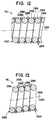
- the staple cartridge 64 includes a plurality of staple receiving slots or pockets 510 which are formed in the housing 440 and arranged in one or more longitudinal rows.
- the staple receiving pockets 510 are arranged in two longitudinal rows ( Figure 27) so that the rows of staples 65 are staggered relative to each other.
- the anvil 68 includes a pair of longitudinally extending rows of staple forming grooves 512 which are arranged in pairs aligned with the staple receiving pockets 510 in the staple cartridge 64.
- the grooves 512 form the staples 65 into a B-shaped configuration when the staple driver 460 is advanced to drive the staples 65 against the anvil 68.
- the right-hand row has nine staple receiving pockets 510 and the left-hand row has ten pockets 510.
- the staple cartridge 64 may include a single row of staple receiving pockets 510, or three or more staggered rows of staple receiving pockets 510.
- the anvil 68 can be modified to include a single row of staple forming grooves 512, or three or more rows of staple forming grooves 512.
- the staple cartridge housing 440 includes a pair of elongated flanges 516 (Figure 27) extending along its opposite sides which serve as cutting guides for a surgical knife or scalpel.
- An elongated notch 520 ( Figures 28 and 29) extends horizontally across the bottom of the staple cartridge housing 440 for receiving a corresponding ridge 522 ( Figure 26) formed on the base member 370 of the anvil 68.
- the channel 520 and the ridge 522 act as a guide mechanism for aligning the anvil 68 with the staple cartridge 64 when the movable jaw 66 is pulled toward the fixed jaw 62.
- the staple driver 460 includes a plurality of staple driving fingers 530 mounted on a central connecting web 532 and arranged in two staggered rows corresponding to the rows of staple receiving pockets 510 in the staple cartridge housing 440.
- the distal end of each staple driving finger 530 has a substantially hexagonal cross section and is slidably received in one of the staple forming pockets 510 which also has a substantially hexagonal shape.
- Each of the staple driving fingers 530 of the staple driver 460 is slidably received between an adjacent pair of ribs 514 ( Figure 29) within the staple cartridge housing 440.
- each of the staple driving fingers 530 has a pair of staple engaging ridges 534 separated by a transversely extending notch 536.
- a pair of staple receiving grooves 538 extends longitudinally across the ridges 534 on opposite sides of each notch 536.
- the cam insert 462 is sandwiched between the two rows of staple driving fingers 530 on the proximal side of the connecting web 532 to strengthen the staple driver 460.
- a pair of positioning fingers 540 and 542 project proximally from the central connecting web 532 in the space between the staple driving fingers 530 on the staple driver 460.
- the positioning fingers 540 and 542 are received in a pair of notches 544 and 546 formed at the distal edge of the staple driver insert 462 to facilitate the assembly of the staple driver 460 and the staple driver insert 462 in the proper orientation.
- the stapling head assembly 60 includes a detent or lock pin 550 for retaining the firing cam 464 in an unfired position before the firing of the staple 65 in the stapling head assembly 60.
- the lock pin 550 has a hollow resilient finger 552 which is snap-fit into a hole formed at the rear of the cover 424.
- the firing cam 464 includes a proximally projecting ledge 554 which is disposed above the resilient finger 552 before the staples 65 are fired to retain the firing cam 464 in its unfired position.
- the ledge 554 flexes the resilient finger 552 out of its way to permit the firing cam 464 to move downward to actuate the staple driver 460 and fire the staples 65.
- the firing cable 190 is a braided cable made of stainless steel filaments.
- the closure cable 230 is made of a compliant material, e.g., VectranTM, manufactured by Hoechst-Celanese, which permits the closure cable to stretch when the stapling instrument 50 is operated.
- the strength of the cables 190 and 230 is designed to achieve the desired staple height at all orientations and articulation angles of the stapling head assembly 60.
- the compliant material of the closure cable 230 permits stretching when the stapling head assembly 60 is pivoted about the vertical axis 52 of the pivot connection 72 so that the force to close the jaws 62 and 66 remains substantially constant.
- the length of the support shaft assembly 70 is adjusted by rotating the adjusting nut 140 to move the tubular support shaft 74 axially and to adjust the tension in the closure cable 230 for closing the jaws 62 and 66.
- the overall length of the support shaft assembly 70 can be adjusted to set a sufficient tension in the closure cable 230 to completely close the jaws 62 and 66 when the jaw closure lever 84 is actuated.
- the half-sections 102 of the control knob 82 are assembled together with the adjusting nut 140.
- the longitudinal ribs 148 ( Figure 15) on the inside of the knob half-sections 102 are received in the grooves 146 on the adjusting nut 140 and in the grooves 152 of the flanges 150 to fix the shaft 74 and the adjusting nut 140 on the control knob 82 and to set the length of the support shaft assembly 70 and the tension in the closure cable 230.
- closure cable 230 pull the anvil 68 toward the staple cartridge 64 with sufficient force to cause the head pin 342 to lock up in the guide slot 386 and to cause the slide pin 380 to lock up in the slots 382 and 384 so that the jaws 62 and 66 are completely closed by the jaw closure lever 84 to produce a uniform staple height when the staple firing lever 86 is actuated.
- the anvil 68 is locked in a closed position parallel to the staple cartridge 64 to provide a uniform spacing therebetween.
- the formed staple height is determined by the fixed distance between the anvil 68 and the staple cartridge 64 and is substantially independent of the tension in the closure cable 230 when the staple firing lever 86 is actuated.
- the tip of the anvil 68 initially contacts the tissue stop 492 on the staple cartridge 64.
- the upward movement of the anvil arm 368 is completed when the lower edge of the guide slot 386 bottoms out against the head pin 342 supported in the holes 340 ( Figure 14) of the head plate 328.
- the bearing pin 342 and the slide pin 380 are slightly smaller in diameter than the width of the anvil slots 382 and 386 to permit the anvil 68 to slide easily during the closure and opening of the jaws 62 and 66.
- the diameter of the bearing pin 342 is also slightly smaller than the diameter of the holes 340 in the head plate 328.
- the firing cable 190 pulls the firing cam 464 downward to advance the staple driver 460 toward the anvil 68.
- the staple driver 460 drives the staples 65 from the staple cartridge 64 into contact with the anvil 68.
- the pressure of the staples 65 causes the tip of the anvil 68 to separate from the tissue stop 492 while the anvil 68 is pivoted in a counter-clockwise direction about the closure cable pin 394.
- the pivotal movement of the anvil 68 causes the slide pin 380 to be shifted proximally by the distal edge of the anvil slot 382 and to bear against the proximal edges of the slots 384 in the head plate 328.
- the counter-clockwise pivoting of the anvil 68 causes the bearing pin 342 to be shifted proximally by the distal edge of the anvil slot 386 and to bear against the proximal sides of the holes 340 in the head plate 328.
- the contact of the bearing pin 342 with the anvil slot 386 and the holes 340 and the contact of the slide pin 380 with the anvil slot 382 and the slots 384 provide a binding action between the anvil 68 and the head plate 328.
- This binding action locks the anvil arm 368 in a predetermined vertical position which is attained when the lower edge of the anvil slot 386 contacts the bottom of the bearing pin 342 in response to the tension of the closure cable 230.
- the binding action results in a formed staple height substantially independent of the tension or strength of the closure cable 230. As a result, the formed height of the staples 65 is more easily controllable and consistent.
- the staples 65 When the staples 65 are forced against the anvil 68 by the staple driver 460, the staples 65 are formed into a desired B-shaped configuration ( Figure 22). Although the anvil 68 deflects under the load of the staple forming forces, the anvil arm 368 does not move vertically downward due to the binding action described above. After the staples 65 are completely formed into the B-shaped configuration, the force of the staples 65 pressing on the anvil 68 is diminished thereby allowing the anvil 68 to return to an unloaded state and to pivot in a clockwise direction. The pivoting of the anvil 68 toward its original position causes the bearing pin 342 and the slide pin 380 to shift back to the positions where the binding action between the anvil 68 and the head plate 328 is released. The anvil 68 is released from its locked position and is easily pushed to its open position by the compression return spring 396 when the tension in the closure cable 230 is released by actuation of the release button 100.
Abstract
Description
- The present invention generally relates to a surgical instrument for applying surgical fasteners to tissue and, more particularly, to a surgical stapling instrument with an articulated stapling head assembly mounted by a rotatable and flexible support shaft on an actuator handle assembly which includes an improved actuator mechanism for closing and firing the stapling head assembly.
- In recent years, there has been an increasing number of surgeons using surgical staples, rather than conventional sutures. This is true because the use of surgical staples and surgical stapling instruments has made many difficult procedures much simpler to perform. Of more importance, however, is that the use of surgical staples significantly reduces the time required for most procedures, and therefore reduces the length of time which the patient must be maintained under anesthetic. Many types of surgical stapling instruments have been devised for different surgical procedures.
- The present invention is directed to a surgical instrument for applying surgical fasteners to internal organs and tissues such as the lung, esophagus, stomach, duodenum, and intestines. The invention is embodied in a linear surgical stapler which permits access to restricted surgical sites, e.g., the pelvic area of the human body.
- In its earliest form, the linear surgical stapling instrument was a permanent, multi-use instrument and the surgical staples were manually loaded into the instrument one at a time. An example of a surgical stapling instrument of this type is disclosed in U. S. Patent 3,080,564. This type of instrument was, in general, complex in construction, expensive to manufacture, heavy, bulky and difficult to both load the surgical staples and to clean and sterilize after each use. A subsequent improvement in linear surgical stapling instruments was the provision of presterilized, disposable loading units or staple cartridges. U. S. Patents 3,275,211, 3,315,863 and 3,589,589 disclose examples of permanent, multi-use linear instruments having replaceable staple cartridges.
- Several types of surgical fastener applying instruments are known for applying surgical fasteners to body tissue clamped between relatively movable fastener holding and anvil portions of the instrument. The surgical fasteners may be metal staples as shown, for example, in U. S. Patent 3,275,211, or consist of non-metallic resinous materials as shown, for example, in U. S. Patent 4,402,445. In the case of metal staples, the staple legs are typically driven through the tissue and formed by the anvil to secure the staples in the tissue. In the case of non-metallic fasteners, each fastener may initially consist of two separate parts, i.e., a fastener part disposed in the fastener holding part of the apparatus, and a retainer part disposed in the anvil part of the apparatus. The leg or legs of the fastener parts are driven through the tissue and interlock with the retainer parts to secure the fasteners in the tissue. Although most surgical staples are biologically inert and remain permanently in the body, biologically absorbable metal surgical staples are known. Surgical fasteners of non-metallic resinous materials can also be made either biologically absorbable or non-absorbable.
- The surgical instrument of the present invention is not limited to use with any particular type or form of fasteners. The various surgical fasteners mentioned above represent examples of the types of fasteners which can be used with the instrument of the present invention. Thus, as used herein, surgical fastener is meant to be generic to all of the above fasteners, including both staples and two-part devices. Similarly, as used herein, fastener holder and anvil are terms which are generic to surgical instruments for applying the above types of fasteners.
- In the prior instruments disclosed in U. S. Patents 3,275,211 and 4,402,445 for applying surgical fasteners to tissue clamped between the fastener holding and anvil portions of the instrument, a distal fastener applying assembly is rigidly connected to the proximal actuator portion of the instrument. More recently, however, there has been increasing interest in instruments in which the connection between the fastener applying assembly and the actuator assembly is not completely rigid. U. S. Patent 4,473,077, for example, shows a surgical stapler in which the shaft assembly connected between the fastener applying and actuator assemblies is transversely flexible in a single plane.
- Also, in view of rising hospital costs, there has been an ever increasing interest in disposable surgical stapling instruments to eliminate as much work as possible, i.e., disassembly, cleaning, reassembly, sterilization and the like, and to be more efficient, while at the same time, not having to compromise the surgical procedures. U. S. Patents 4,354,628, 4,383,634 and 4,527,724, for example, each disclose disposable linear surgical stapling instruments. A surgical fastener applying apparatus is disclosed in U. S. Patent 4,566,620 including a fastener applying assembly rotatably mounted at the distal end of a longitudinal shaft assembly by a joint for allowing rotation of the fastener applying assembly relative to the actuator assembly about each of three mutually orthogonal axes. U. S. Patents 4,728,020 and 4,869,414 also disclose surgical fastener applying instruments.
- Additional examples of surgical instruments including a fastener applying assembly provided with relatively movable fastener holding and anvil portions are disclosed in U. S. Patents 4,591,085 and 4,941,623. The instrument disclosed in U. S. Patent 4,591,085 includes a trigger interlocking mechanism which precludes the actuation of the trigger until an appropriate gap is set between the jaws of the instrument.
- U. S. Patent 4,938,408 discloses a surgical stapling instrument including a rotatable support shaft on which a stapler head is rotatably mounted for rotation about an axis normal to the axis of the support shaft. U. S. Patent 5,137,198 discloses a linear surgical stapling instrument including a fast jaw closure mechanism and a trigger safety device.
- In co-pending U. S. patent application Serial No. 832,299, filed on February 7, 1992, entitled "Surgical Anastomosis Stapling Instrument With Flexible Support Shaft And Anvil Adjusting Mechanism", assigned to the same assignee as the present invention, a surgical stapling instrument including a flexible shaft assembly is disclosed. The flexible shaft assembly comprises a pair of elongated helical elements which are concentrically wound together with the coils of the first helical element alternately interspersed with the coils of the second helical element. Each coil of the first helical element has a round cross section and each coil of the second helical element has a triangular cross section provided with sloped surfaces which slidably engage the adjacent round coils.
- In co-pending U. S. Patent Application Serial No. , filed on December 6, 1993, entitled "Surgical Stapling Instrument With Articulated Stapling Head Assembly On Rotatable And Flexible Support Shaft", assigned to the same assignee as the present invention, a surgical stapling instrument is disclosed which includes an actuator handle assembly with a pivotally mounted jaw closure lever and a staple firing lever pivotally mounted on the jaw closure lever. The jaw closure lever operates a closure cable for closing the jaws of a stapling head assembly to clamp the tissue therein. The staple firing lever operates a firing cable for actuating a staple driver to drive surgical staples from a staple holder into the clamped tissue. A pulley is rotatably mounted on the jaw closure lever. The firing cable travels around the pulley and is secured to the staple firing lever which applies tension to the firing cable when the staple firing lever is actuated. The pulley is not secured to the firing cable and is not coupled by any drive mechanism for rotation by the staple firing lever.
- In manually operated medical instruments, e.g.. surgical staplers, it is advantageous to operate within the hand strength and grasp size limitations of the persons who will actually operate the instruments. With many medical instrument functions, such as staple firing, the force or load applied to the actuator cable is non-uniform over the required firing stroke. The load is low during early portions of the stroke when the staples are advancing out of the cartridge and piercing the tissue. Once the staples bottom in the anvil pockets, the resistance and load rise rapidly as the staple legs buckle. Then the resistance and load drop down and rise again as the final forming of the staples into a B-shaped configuration occurs. In contrast, the operator has maximum effective strength at the mid-portion of the stroke of the instrument. At the final portion of the stroke, it is advantageous to require a lower operating force to make it easier to over-travel another lever for reopening of the instrument. In addition, it is easier for the operator to complete the firing stroke if the input load drops off at the end of the stroke.
- Accordingly, it is an object of the present invention to provide a surgical instrument for applying surgical fasteners, such as surgical staples, with an improved actuator mechanism which operates within the hand strength and grasp size limitations of the operator.
- Another object of the invention is to provide a surgical stapling instrument with an improved actuator mechanism in which a pulley is secured to an actuator cable and rotated by a staple firing lever to fire the staples.
- It is also an object of the invention to provide a surgical stapling instrument with an improved actuator mechanism which includes a cam pulley secured to a actuator cable and rotatable by a staple firing lever for operating the actuator cable with different mechanical advantages as the cam pulley is rotated to fire the staples.
- A further object of the invention is to provide a surgical stapling instrument with an improved actuator mechanism including a cam pulley secured to an actuator cable and rotatable by a staple firing lever which includes an anti-backup mechanism to prevent the pay-out of the actuator cable before and after the staples are fired.
- The present invention achieves an improved surgical instrument for applying surgical fasteners, such as staples, to human tissue which is particularly suited for applying one or more rows of fasteners across a tissue lumen to produce a fluid tight closure of the lumen. The surgical instrument of this invention is intended for use in thoracic and abdominal surgical procedures in which single fire surgical staplers are currently used and where access to the surgical site is restricted. For example, the surgical instrument can be used in the following types of procedures: (1) a double stapling technique, especially for a low anterior re-section, (2) closure of the bronchus during a lobectomy or pneumonectomy, (3) closure of the esophagus in esophageal procedures, and (4) closure of the pulmonary blood vessels during a lobectomy or pneumonectomy.
- The present invention is embodied in a surgical stapling instrument for applying one or more surgical staples to tissue which comprises a stapling head assembly including a first jaw with a staple holder for receiving one or more surgical staples, a second jaw with an anvil for clamping the tissue against the staple holder when the jaws are closed, and a staple driver for driving the staples from the staple holder into the tissue and against the anvil, and an actuator handle assembly including a jaw closure lever for closing the jaws and a staple firing lever for actuating the staple driver. The stapling instrument includes a closure cable operable by the jaw closure lever for closing the jaws to clamp the tissue between the anvil and the staple holder and a firing cable operable by the staple firing lever for actuating the staple driver to drive the staples into the tissue and against the anvil. A pulley is rotatably mounted on the actuator handle assembly and secured to the firing cable for applying tension to the firing cable when the pulley is rotated by the staple firing lever to actuate the staple driver.
- In a preferred embodiment, the stapling instrument includes drive means coupling the staple firing lever to the pulley and rotating the pulley when the staple firing lever is actuated to apply tension to the firing cable to actuate the staple driver. The drive means comprises a pair of drive gears rotatably positioned on opposite sides of the pulley and provided with a set of drive lugs positioned for movement into engagement with a set of side lugs on the pulley when the drive gears are rotated. A pair of gear sectors on the staple firing lever is engaged with the drive gears for rotating the drive gears when the staple firing lever is actuated to move the drive lugs into engagement with the side lugs to rotate the pulley and to apply tension to the firing cable.
- In the preferred embodiment of the stapling instrument, the pulley includes a contoured cam lobe for actuating the firing cable with different mechanical advantages as the pulley is rotated. Preferably, the cam lobe includes a first cam region with a large lobe height to provide a small mechanical advantage for actuating the firing cable, a second cam region with an intermediate lobe height which provides an increasing mechanical advantage, and a third cam region with a small lobe height which provides a large mechanical advantage.
- In accordance with another aspect of the invention, the stapling instrument includes anti-backup means for engaging the pulley to prevent the pay-out of the firing cable before and after the staple firing lever is actuated. Preferably, an anti-backup member is located on the actuator handle assembly adjacent to the periphery of the pulley. A first detent on the pulley engages the anti-backup member to stop the rotation of the pulley in a first position and prevent the pay-out of the firing cable before the firing lever is actuated. A second detent on the pulley engages the anti-backup member to stop the rotation of the pulley in a second position and prevent the pay-out of the firing cable after the firing lever is actuated.
- In accordance with another feature of the invention, the surgical instrument includes latch means mounted on the actuator handle assembly for latching the jaw closure lever in a closed position when the jaws are closed, and a manually operable release button mounted on the actuator handle assembly for actuating the latch means to unlatch the jaw closure lever and allow the jaw closure lever to return to an open position to open the jaws. Preferably, the release button includes an anti-backup member which extends adjacent to the periphery of the pulley for engaging the first and second detents before and after the staple firing lever is actuated to prevent the pay-out of the firing cable.
- In a preferred embodiment of the surgical stapling instrument, a support shaft assembly is provided for mounting the stapling head assembly on the actuator handle assembly. The stapling head assembly includes a proximal jaw which supports a staple holder for receiving one or more surgical staples, a distal jaw which supports an anvil for clamping the tissue against the staple holder when the jaws are closed, a staple driver for driving the staples into the tissue and against the anvil, and a firing cam for actuating the staple driver. The actuator handle assembly includes a jaw closure lever pivotally mounted thereon for closing the jaws and a staple firing lever pivotally mounted on the jaw closure lever for actuating the staple driver. The stapling instrument includes a closure cable connected to the distal jaw and operable by the jaw closure lever for moving the distal jaw relative to the proximal jaw to clamp the tissue between the anvil and the staple holder. The stapling instrument also includes a firing cable connected to the firing cam and operable by the staple firing lever for actuating the staple driver to drive the staples into the tissue and against the anvil. A pulley is rotatably mounted on the actuator handle assembly and secured to the firing cable for applying tension to the firing cable when the pulley is rotated by the staple firing lever to actuate the firing cam and the staple driver.
- In accordance with another feature of the actuator handle assembly, the surgical instrument includes a control link slidably and pivotally mounted on the actuator handle assembly and operable by the jaw closure lever for applying tension to the closure cable to pull the distal jaw toward the proximal jaw. Preferably, the closure cable comprises a continuous belt with loops at its opposite ends connected to the distal jaw and to the control link.
- In a preferred embodiment of the stapling head assembly, the distal jaw includes an anvil member having an upstanding anvil arm and a base portion provided with one or more elongated slots for receiving one or more slide pins to connect the anvil member to the proximal jaw. The distal jaw also includes a shroud member including a pair of side plates which span the opposite sides of the base member and retain the slide pins in the guide slots. Also, in the stapling head assembly, detent means is provided for retaining the firing cam in an unfired position before the staple firing lever is actuated.
- Preferably, the shaft assembly is rotatable about its longitudinal axis to orient the stapling head assembly in different angular orientations relative to the actuator handle assembly. A cable support member mounted inside the shaft assembly includes a pair of longitudinal passageways for receiving the firing cable and the closure cable. The cable support member is capable of twisting when the shaft assembly is rotated about its longitudinal axis to prevent the firing cable and the closure cable from twisting together.
- In accordance with another aspect of the invention, the stapling instrument includes means for adjusting the length of the shaft assembly to set the tension in the closure cable to close the jaws when the jaw closure lever is actuated. The shaft assembly is adjusted in length during the assembly of the instrument to provide sufficient tension in the closure cable so that the jaws are completely closed by the jaw closure lever to produce a uniform staple height when the staple firing lever is actuated.
- The foregoing and other objects, aspects and advantages will be better understood from the following detailed description of the preferred embodiments of the invention with reference to the drawings, in which:
- Figure 1 is a perspective view of a surgical stapling instrument constructed in accordance with this invention including a support shaft assembly with a flexible section for mounting a stapling head assembly on an actuator handle assembly;
- Figure 2 is a side elevation of the surgical stapling instrument of Figure 1;
- Figure 3 is a side view of the flexible section of the support shaft assembly of Figure 2 in a bent configuration to adjust the orientation of the stapling head assembly;
- Figure 4 is an enlarged, partially cutaway longitudinal section of the support shaft assembly of the surgical stapling instrument of Figure 2;
- Figure 5 is an enlarged partially cutaway side elevation showing a flexible section of the support shaft assembly of Figure 4;
- Figure 6 is a partially cutaway side view of an actuator mechanism contained within the actuator handle assembly of Figure 2;
- Figure 7 is an enlarged, partially cutaway side elevation of the stapling head assembly of Figure 2;
- Figure 8 is a partially cutaway side view of a jaw closure lever within the actuator mechanism of Figure 6;
- Figure 9 is an enlarged, partially cutaway side view of a tissue retaining pin mechanism within the stapling head assembly of Figure 2;
- Figure 10 is a partially cutaway side view of a stapling firing lever in the actuator mechanism of Figure 6;
- Figure 11 is an enlarged longitudinal section showing a firing cam mechanism within the stapling head assembly of Figure 2;
- Figure 12 is an enlarged longitudinal section showing a portion of the flexible support shaft of Figure 5 in a straight condition;
- Figure 13 is an enlarged longitudinal section showing a portion of the flexible support shaft of Figure 5 in a bent condition;
- Figure 14 is an exploded perspective view showing the components of the actuator mechanism in the actuator handle assembly of Figure 6;
- Figure 15 is an exploded perspective view of a shaft adjusting mechanism in the actuator handle assembly of Figure 6;
- Figure 16 is an exploded perspective view of the components of the stapling head assembly;
- Figure 17 is a partially cutaway side view showing the actuator mechanism in a partially closed position;
- Figure 18 is an enlarged, partially cutaway side view showing the stapling head assembly in a partially closed position;
- Figure 19 is a partially cutaway side view showing the actuator mechanism in a closed and ready to fire position;
- Figure 20 is an enlarged, partially cutaway side view showing the stapling head assembly in a closed and ready to fire position;
- Figure 21 is a partially cutaway side view showing the actuator mechanism in a closed and fired position;
- Figure 22 is an enlarged, partially cutaway side view showing the stapling head assembly in a closed and fired position;
- Figure 23 is a partially cutaway side view showing the actuator mechanism in an over-travel position;
- Figure 24 is a partially cutaway side view showing the actuator mechanism in a fired and reopened position;
- Figure 25 is an enlarged, partially cutaway side view showing the stapling head assembly in a re-opened position;
- Figure 26 is an enlarged, partially cutaway proximal view of the anvil on the movable jaw of the stapling head assembly;
- Figure 27 is an enlarged, partially cutaway distal view of the staple cartridge on the fixed jaw of the stapling head assembly;
- Figure 28 is an enlarged, partially cutaway side view of the staple cartridge of the stapling head assembly;
- Figure 29 is an enlarged vertical section of the staple cartridge along line 29-29 of Figure 28;
- Figure 30 is an enlarged front or distal view of the staple driver of the stapling head assembly;
- Figure 31 is a partially cutaway side view of the staple driver of Figure 30;
- Figure 32 is an enlarged side view of a pin in the pivot connection of the stapling head assembly;
- Figure 33 is a rear view of the pivot pin of Figure 32;
- Figure 34 is a horizontal section of the pivot pin along line 34-34 of Figure 32;
- Figure 35 is an enlarged side view of a cam pulley of the actuator mechanism;
- Figure 36 is a bottom view of the cam pulley of Figure 35;
- Figure 37 is a top view of the cam pulley of Figure 35;
- Figure 38 is a vertical section of the cam pulley along line 38-38 of Figure 37;
- Figure 39 is an enlarged section of a cable support member in the support shaft assembly;
- Figure 40 is an enlarged fragmentary view of the staple firing lever of Figure 10;
- Figure 41 is an enlarged front view of a control link of the actuator mechanism;
- Figure 42 is an enlarged proximal end view of the pivot connection on the stapling head assembly;
- Figure 43 is an enlarged front view of a stop plate on the actuator handle assembly; and
- Figure 44 is a vertical section of the stop plate along line 44-44 of Figure 43.
- Referring to Figure 1, the present invention is embodied in a surgical stapling instrument, generally 50, which includes a distal
stapling head assembly 60 connected by asupport shaft assembly 70 to a proximalactuator handle assembly 80. The staplinghead assembly 60 includes a proximal or fixedjaw 62 which supports astaple cartridge 64 and a distal ormovable jaw 66 which supports a staple forming anvil 68 (Figure 2). Thestaple cartridge 64 receives one or more rows of staples 65 (Figure 17) which are driven against theanvil 68 and formed into a B-shaped configuration to fasten tissue together. For example, nineteen staples are held in thestaple cartridge 64 and arranged in two staggered rows. It will be understood by persons skilled in the art that thesurgical stapling instrument 50 can be adapted to operate with two-part surgical fasteners instead of thestaples 65. - As shown in Figure 1, the proximal or fixed
jaw 62 is mounted in a hinge-like fashion on apivot connection 72 which permits the staplinghead assembly 60 to pivot about avertical axis 52 into different angular orientations relative to a centerline orlongitudinal axis 54 of thesupport shaft assembly 70. For example, thepivot connection 72 is arranged to allow the staplinghead assembly 60 to pivot about thevertical axis 52 in approximately 20° increments. The articulatedstapling head assembly 60 is pivotable either clockwise or counterclockwise about thevertical axis 52 to positions oriented at about ±20°, ±40°, ±60° and ±80° relative to the longitudinal axis orcenterline 54. Thesupport shaft assembly 70 is rotatably mounted on theactuator handle assembly 80 for rotation about the longitudinal axis orcenterline 54. Preferably, thesupport shaft assembly 70 is rotatable over an angular range of approximately 180° or more about thecenterline 54. Acontrol knob 82 is coupled to thesupport shaft assembly 70 and rotatably mounted at the distal end of theactuator handle assembly 80 to allow thesupport shaft assembly 70 to be rotated about itsaxis 54 to adjust the rotational orientation of the staplinghead assembly 60. - The
shaft assembly 70 includes atubular support shaft 74 rotatably mounted on theactuator handle assembly 80 and secured by acoupling sleeve 75 to a flexibletubular shaft 76. The flexibletubular shaft 76 is capable of bending in any radial direction relative to thecenterline 54 of theshaft assembly 70 into a bent or curved shape (Figure 3). The hinge-like pivot connection 72 is mounted on acoupling sleeve 78 at the distal end of theflexible shaft 76. Thetubular support shaft 74 can be made of plastic material. Thecentral coupling sleeve 75 and thedistal coupling sleeve 78 can be made of metal, e.g., aluminum. - The
actuator handle assembly 80 includes a pivotally mountedclosure lever 84 for closing themovable jaw 66 toward the fixedjaw 62 to clamp a tubular section of tissue between thejaws actuator handle assembly 80 also includes a pivotally mountedfiring lever 86 for actuating the staplinghead assembly 60 to drive the staples from thestaple cartridge 64 through the tissue and to form the staples against theanvil 68. - As shown in Figure 1, the
actuator handle assembly 80 includes a pair ofhollow handle sections handle sections handle grip 96. A manuallyoperable release button 100 protrudes upwardly at the proximal end of theactuator handle assembly 80. - Referring to Figures 1 and 15, the
control knob 82 comprises a pair of hollow tapered cylindrical half-sections 102 made of plastic material which can be welded or snap fit together. Each of the knob half-sections 102 has a recessedfinger grip area 104 which facilitates the manual engagement and operation of thecontrol knob 82. Also, each knob half-section 102 has a semi-circularproximal flange 106 provided with aresilient finger 108 which projects radially outward from thesemi-circular flange 106. Each radially projectingfinger 108 engages a series of serrations orteeth 110 which are arranged along a semi-circular path adjacent to the distal end of each of thehandle sections resilient fingers 108 and theserrations 110 provide a detent mechanism which defines fourteen angular positions uniformly spaced apart for rotation of theshaft assembly 70. When the knob half-sections 102 are assembled together and inserted into the distal end of theactuator handle assembly 80, thesemi-circular flanges 106 form a hub which is rotatably supported by an inwardly projectingsemi-circular flange 112 formed at the distal end of each of thehandle sections semi-circular flanges 106 are rotatably supported by asemi-circular rib 114 formed on the interior of each of thehandle sections semi-circular flanges 112 and thesemi-circular ribs 114 provide bearing surfaces to facilitate the rotation of thecontrol knob 82. In addition, asemi-circular ridge 116 formed on the outside of eachsemi-circular flange 106 is located inside thesemi-circular flange 112 at the proximal end of each of thehandle sections control knob 82 relative to thehandle assembly 80. - Referring to Figures 1 and 14, the
actuator handle assembly 80 includes an actuator mechanism, generally 120, contained within the hollowplastic handle sections actuator mechanism 120 includes a pair ofouter support plates 122 which are similar in shape to thehandle sections handle sections support plates 122 in a fixed position within theactuator handle assembly 80 when thehandle sections support plates 122 can be integrally formed on the interior of thehandle sections support plates 122 are fastened together in a spaced parallel relationship by a pair of transverse connectingpins 124 located adjacent to the distal ends of thesupport plates 122 and by a pair of connectingpins 126 extending transversely between a pair of dependinggrip portions 128 of thesupport plates 122. A doublestep pivot pin 130 is mounted in a pair ofholes 131 formed in the top proximal portions of thesupport plates 122 and pivotally supports the other components of theactuator mechanism 120. Thesupport plates 122 are also joined together by a front connectingpin 132 and arear connecting pin 134 which pivotally supports therelease button 100. A pair of opposedsemi-circular flanges 136 which extend axially from the distal ends of thesupport plates 122 are received between thesemi-circular flanges 106 of the knob half-sections 102 (Figure 8). - As shown in Figures 10 and 15, the
tubular support shaft 74 has a threadedproximal end 138 which is threadably received in an adjustingnut 140 having an elongatedtubular body 142 located between thesemi-cylindrical flanges 136 of thesupport plates 122. The adjustingnut 140 has an enlargeddistal end 144 provided with a series of circumferentially spacedlongitudinal grooves 146 which are adapted to receive a pair of opposed longitudinal ribs 148 (one shown) formed on the inside of the knob half-sections 102. Similarly, thetubular support shaft 74 has a pair of diametricallyopposed flanges 150 adjacent to its threadedproximal end 138 which are provided withlongitudinal grooves 152 for receiving thelongitudinal ribs 148 on the inside of the knob half-sections 102. The adjustingnut 140 allows the effective length of thesupport shaft assembly 70 to be adjusted by rotation of the adjustingnut 140 on the threadedproximal end 138 of thetubular support shaft 74 during the assembly of the staplinginstrument 50. After the adjustingnut 140 is rotated to set the desired shaft length, the knob half-sections 102 are assembled together at the proximal end of thetubular support shaft 74. Thelongitudinal ribs 148 which are received in thelongitudinal grooves tubular support shaft 74 and the adjustingnut 140 after the assembly of the staplinginstrument 50 to maintain the desired shaft length. - Referring to Figure 14, the
actuator mechanism 120 includes a pair ofclosure lever plates 154 each including apivot hole 156 for receiving the doublestep pivot pin 130 to pivotally support theclosure lever plates 154 for pivotal movement relative to thesupport plates 122. Theclosure lever plates 154 are maintained in a spaced parallel relationship by the doublestep pivot pin 130 which rotatably supports acam pulley 160. Theclosure lever plates 154 include elongated dependinglever portions 162 which are contained inside a hollow plastic closure lever shroud 164 (Figure 6) to provide thejaw closure lever 84 of theactuator handle assembly 80. - As shown in Figure 14, the
staple firing lever 86 is pivotally mounted between theclosure lever plates 154 by a pair of transverse pivot pins 168 (one shown) extending from its opposite sides and rotatably received in a pair of pivot holes 170 (one shown) formed in theclosure lever plates 154. Thestaple firing lever 86, preferably made of molded plastic material, includes a pair ofgear sectors 172 which are spaced apart to receive thecam pulley 160 therebetween. A pair of firing lever deployment pins 174 extend transversely from the opposite sides of thegear sector 172. The firing lever deployment pins 174 are slidably received in a pair of arc-shapedslots 178 formed in theclosure lever plates 154. The outer ends of the firing lever deployment pins 174 extend through the arc-shapedslots 178 into a pair of firing leverdeployment cam slots 180 formed in thesupport plates 122. Eachcam slot 180 includes a lowercam track section 182 and an uppercam track section 184 which intersect at arear corner 185. - As shown in Figure 40, each firing
lever deployment pin 174 has acylindrical base 175 which is slidably received in the corresponding arc-shapedslot 178 of theclosure lever plate 154. The outer end of eachdeployment pin 174 comprises arectangular block 176 which is slidably received in the correspondingcam slot 180 of thesupport plate 122. On the outer edge of therectangular block 176 is adiagonal cam 186 which cooperates with a rectangular ledge 188 (Figure 15) formed on each of thehandle sections staple firing lever 86. - Referring to Figure 14, a
staple firing cable 190 is anchored to thecam pulley 160 by acable crimp member 192 at the proximal end of the firingcable 190. Preferably, the firingcable 190 is made of stainless steel and thecable crimp member 192 is made of stainless steel which is crimped onto thestaple firing cable 190. Before crimping, thecable crimp member 192 is cylindrical in shape with an axial bore for receiving thestaple firing cable 190. After thestaple firing cable 190 is inserted, thecable crimp member 192 is crimped, for example, into a hexagonal cross section. The hexagonalcable crimp member 192 is anchored to thecam pulley 160 to apply tension to the firingcable 190 when thecam pulley 160 is rotated. - As shown in Figure 14, the
actuator mechanism 120 includes a pair of drive gears 194 which mesh with thegear sectors 172 of thestaple firing lever 86. The drive gears 194 are positioned on opposite sides of thecam pulley 160 and are rotatable about thepivot pin 130. Each of the drive gears 194 has adrive lug 196 for movement into engagement with a pair of side lugs 198 at the top of thecam pulley 160 when the drive gears 194 are rotated. Initially, the drive gears 194 are free to rotate relative to thecam pulley 160 until the drive lugs 196 on the drive gears 194 engage the side lugs 198 on thecam pulley 160. When the drive lugs 196 and the side lugs 198 are engaged, the drive gears 194 and thecam pulley 160 rotate together in a clockwise direction to apply tension to thestaple firing cable 190. - Referring to Figures 35-38, the
cam pulley 160 comprises a pair of disc-shapedside members 200 which are integrally formed with and separated by aninterior cam member 202. Thecam member 202 has a hexagonally shapedpassage 204 in which the hexagonalcable crimp member 192 is anchored to secure the firingcable 190 to thecam pulley 160. Thecam pulley 160 has a first set ofteeth 206 formed at the periphery of the disc-shapedside members 200 which engage ananti-backup tang 208 on therelease button 100 to hold thecam pulley 160 in position during storage and prior to the firing of the staplinginstrument 50. Thecam pulley 160 has a second set ofteeth 209 formed at the periphery of the disc-shapedside members 200 which engage theanti-backup tang 208 after the staplinginstrument 50 is fired to control the pay-out of thestaple firing cable 190. The side lugs 198 extend radially at the periphery of the disc-shapedside members 200 and are aligned with the second set ofteeth 209. Atubular spring pin 199 is inserted in a pair of holes in the side lugs 198. - In another embodiment of the
actuator mechanism 120, theanti-backup tang 208 can be eliminated from the release button 100 (Figure 14) and thecam pulley 160 can be formed without the first andsecond teeth 206 and 209 (Figure 38) to eliminate the anti-backup feature. Also, the drive gears 194 can be formed on thecam pulley 160 to reduce the number of components in theactuator mechanism 120. - As shown in Figure 38, the
interior cam member 202 of thecam pulley 160 comprises a contoured cam lobe of varying height for actuating the firingcable 190 with different mechanical advantages as thepulley 160 is rotated. Thecam lobe 202 includes afirst cam region 210 with a large lobe height to provide a small mechanical advantage for actuating the firingcable 190, asecond cam region 211 with an intermediate lobe height which provides an increasing mechanical advantage, and athird cam region 212 with a small lobe height which provides a large mechanical advantage. Thecam region 210 engages the staple firing cable during the initial portion of the stroke of thestaple firing lever 86 and thecam region 212 engages thestaple firing cable 190 during the final portion of the stroke of thestaple firing lever 86. - Referring to Figures 14 and 41, the
actuator mechanism 120 includes a closure control link 214 comprising a pair of triangularly shapedside members 216 which are joined together in a spaced parallel relationship by an integrally formedbridge pin 218. A first pair of pivot pins 220 extend transversely in opposite directions from the lower end of thelink 214. The outer ends of the pivot pins 220 are slidably received in a pair ofinclined guide slots 222 formed in thesupport plates 122. A second pair of pivot pins 224 at the upper end of thelink 214 extend transversely in opposite directions from theside members 216. The pivot pins 224 are received in a pair of pivot holes 226 formed in a pair ofdistal fingers 228 on theclosure lever plates 154. Ajaw closure cable 230 is looped over the bridge pin 218 (Figure 10) between theside members 216 of theclosure control link 214. The closure control link 214 pivots clockwise while the pivot pins 220 slide rearwardly in theguide slots 222 to apply tension to thejaw closure cable 230 when theclosure lever plates 154 are actuated by thejaw closure lever 84. At the base of eachpivot pin 222 is a raisedbearing surface 225 which slides along the inside of thecorresponding support plate 122 when thecontrol link 214 is pivoted by thejaw closure plates 154. - The
staple firing cable 190 and thejaw closure cable 230 extend through astop plate 232 located adjacent to the distal end of thesupport shaft assembly 70. A hollowcylindrical body 234 at the distal end of thestop plate 232 extends into the proximal end of thetubular body 142 of the adjustingnut 140. As shown in Figures 43 and 44, a pair of bearingsurfaces 235 is formed on the distal side of thestop plate 232 for engaging thesemi-circular flanges 106 which form the hub of thecontrol knob 82. Thestop plate 232 has a centralrectangular slot 236 for receiving the firingcable 190 and theclosure cable 230. Thestop plate 232 includes a pair oftabs 238 projecting laterally from its opposite sides which are received in a pair of mounting holes 240 (Figure 14) formed in thesupport plates 122. - Referring to Figures 10 and 14, the
release button 100 comprises a hollow molded plastic body including a pair of dependingflanges 250 on its opposite sides each including a pivot hole 252 for receiving the connectingpin 134 to pivotally mount therelease button 100 on thesupport plates 122. Therelease button 100 also has a dependingrear finger 254 provided with a laterally projectingtab 256 which cooperates with a cylindrical female connector 258 (Figure 10) on the inside of one of thehandle sections release button 100 relative to theactuator handle assembly 80. Pivotally mounted underneath therelease button 100 is arelease lever 260 which is normally urged by arelease spring 262 into engagement with the dependingfinger 254 of therelease button 100. Therelease lever 260 has a lower pair of pivot pins 264 (one shown) extending transversely in opposite directions therefrom which are received in a pair of pivot holes 266 formed in thesupport plates 122. As shown in Figure 6, the pivot holes 266 are enlarged so that the pivot pins 264 are free to slide and pivot relative to thesupport plates 122. Therelease lever 260 has alatch arm 268 provided with an upper pair of guide pins 270 extending transversely in opposite directions therefrom which are received in a pair ofguide slots 272 formed in thesupport plates 122. Acam 274 on the underside of therelease lever 260 is engaged by therelease spring 262 to urge therelease lever 260 into engagement with the dependingfinger 254 of therelease button 100. Therelease spring 262 comprises an elongated flat metal strip which is curled at its opposite ends to form a pair of hollowcylindrical flanges cylindrical flange 276 is mounted on the lower connectingpin 126. The release spring is flexed about the upper connectingpin 126 and the uppercylindrical flange 278 engages thecam 274 on therelease lever 260. Therelease spring 262 provides a biasing force which urges therelease lever 260 against the dependingfinger 254 to bias therelease button 100 in a counterclockwise direction about thepivot pin 134. - As shown in Figure 10, each of the
closure lever plates 154 has a proximally extendinglatch lug 280 located adjacent to therelease lever 260. When thejaw closure lever 84 is actuated to pivot theclosure lever plates 154 about the pivot pin 130 (Figure 17), the latch lugs 280 engage thearm 268 and pivot theclosure lever 260 clockwise against the bias of therelease spring 262. When thejaw closure lever 84 is moved to its fully closed position (Figure 19), therelease lever 260 is biased counter-clockwise by therelease spring 262 to move thelatch arm 268 underneath the latch lugs 280 to latch thejaw closure lever 84 in its fully closed position. Thelugs 280 cam against therelease lever 260 and therelease spring 262 tends to resist the pivotal movement of theclosure lever plates 154 relative to thesupport plates 122 when thejaw closure lever 84 is moved toward its closed position. The camming action of thelugs 280 and therelease lever 260 prevents rattling of theactuator mechanism 120 and assists in holding thejaw closure lever 84 in its open position. - Referring to Figures 4 and 5, the flexible
tubular support shaft 76 comprises a dual helical coil structure comprising a first elongatedhelical member 282 and a second elongatedhelical member 284 which are concentrically wound together with thecoils 286 of the firsthelical member 282 alternately interspersed with thecoils 288 of the secondhelical member 284. As shown in Figure 4, eachcoil 286 of thehelical member 282 has a round cross section. Eachcoil 288 of thehelical member 284 has a triangular, wedge-shaped cross section defining a pair of inwardly sloped surfaces 290 which engage the round exterior surfaces of the adjacent round coils 286. The wedge-shapedcoils 288 are positioned between theround coils 286 to maintain a desired separation between the adjacent round coils 286 and to maintain the firsthelical member 282 in tension. Thehelical coil members flexible shaft 76 to be bent in any radial direction relative to the longitudinal axis or centerline 54 (Figure 3) of thesupport shaft assembly 70. Inside thehelical coil members cable support tube 292, preferably made of a malleable metal such as aluminum, which allows theflexible shaft 76 to assume its bent or curved shape. Thecable support tube 292 is flexible in any radial direction relative to the longitudinal axis orcenterline 54 of thesupport shaft assembly 70. Thecable support tube 292 enables theflexible support shaft 76 to assume its curved configuration and to resist tension from thecables head assembly 60 is actuated. - In the preferred embodiment, the
flexible support shaft 76 is adapted to be bent within a predetermined range, e.g., up to about ±30° in any direction from its straight configuration. After bending, theflexible support shaft 76 maintains its bent shape (Figure 3) until theshaft 76 is further manipulated. The malleable cable support tube 292 (Figure 4) prevents thebent support shaft 76 from inadvertently straightening. This shape retention feature permits access of the staplinghead assembly 60 into the pelvic cavity while avoiding contact of theactuator handle assembly 80 with the viscera or body wall. Thehelical coil members shaft assembly 70 remains a substantially constant length during the bending of theflexible support shaft 76. This feature avoids any undesirable change in length which would result in motion of the taut cable system. The twin helical coil construction also provides a solid load path which resists the compressive forces during closure and firing while avoiding any tendency for theflexible support shaft 76 to return to the straight condition. - In addition, the geometry of the
circular coils 286 and thetriangular coils 288 is such that, at a bending angle of about 30°, one or the other of the coils becomes solid, i.e., either the adjacent round coils 286 engage each other or the adjacenttriangular coils 288 engage each other. This condition causes a sharp increase in the force required to bend theflexible support shaft 76 and provides a limit on the extent of the bending motion. This limitation on the angle of bend keeps the cable friction forces low so that the system operates in the regime of substantially constant axis length. The malleablecable support tube 292 is free to slide axially within thehelical members cable support tube 292 due to plastic deformation does not effect the force required to bend theflexible support shaft 76. - Referring to Figure 5, in a preferred embodiment of the
flexible support shaft 76, the wedge-shapedcoils 288 are reduced in width compared with the diameter of the round coils 286. Also, the wedge-shapedcoils 288 are shaped to allow the adjacent round coils 286 on the inside of the bend to engage each other when theflexible support shaft 76 is bent to about a 30° bending angle. The helicalcoil spring member 282 and the helicalwrap wire member 284 are coiled together along a commonlongitudinal axis 285 with the round coils 286 alternating with the triangular or wedge-shapedcoils 288 and thecoil spring member 282 in tension. Thewrap wire member 284 is wrapped about thecoil spring member 282 with the wedge-shapedcoils 288 positioned between theround coils 286 to maintain a desired separation between the adjacent round coils 286 when thesupport shaft assembly 76 is straight. The wedge-shapedcoils 288 are forced between the adjacent round coils 286 to maintain thecoil spring member 282 in tension. Thecoil spring members linear weld areas 294 adjacent to the opposite ends of theflexible support shaft 76. The details of theflexible support shaft 76, thecoil spring member 282, thewrap wire member 284, the round coils 286 and the wedge-shapedcoils 288 are described in a co-pending U. S. Patent Application entitled "Flexible Support Shaft Assembly", which was filed on December 6, 1993 and assigned to the same assignee, Ethicon, Inc., as the present application. This prior co-pending application is herein incorporated by reference. - As shown in Figure 12, each of the wedge-shaped
coils 288 initially separates the adjacent round coils 286 longitudinally from each other when theflexible support shaft 76 is straight. The round coils 286 and the wedge-shapedcoils 288 are aligned along the commonlongitudinal axis 285. The wedge-shapedcoils 288 are slidable relative to the round coils 286 to allow theflexible support shaft 76 to bend in a transverse direction relative to itslongitudinal axis 285. The sliding action of the wedge-shapedcoils 288 allows theflexible support shaft 76 to bend until the round coils 286 on the inside of the bend engage each other and limit the bending of theflexible support shaft 76. - Referring to Figure 13, as the
flexible support shaft 76 is bent transversely relative to itslongitudinal axis 285, the wedge-shapedcoils 288 are shifted laterally relative to the adjacent round coils 286. Also, thelongitudinal axis 289 of the wedge-shapedcoils 288 is shifted slightly relative to thelongitudinal axis 285 of the round coils 286 in the direction of the bending of theflexible support shaft 76. The portions of the round coils 286 on the inside of the bend move closer together while the portions of the round coils 286 on the outside of the bend move farther apart. As a result of the sliding action of the wedge-shapedcoils 288 relative to the round coils 286, theflexible support shaft 76 is bent into a curved configuration. The bending of theflexible support shaft 76 occurs without any substantial change in the overall length of the flexiblesupport shaft assembly 76 and without stretching of thecoil spring member 282 along itsaxis 285 until the round coils 286 on the inside of the bend move into engagement with each other. Up to this point, the bending of theflexible support shaft 76 can be accomplished by applying a relatively small bending force to thecoil spring member 282 and thewrap wire member 284. - After the round coils 286 on the inside of the bend engage each other, a substantially increased bending force must be applied to obtain any further bending of the
flexible support shaft 76 in the same direction. Because the portions of the round coils 286 on the inside of the bend are in contact with each other, any additional bending of theflexible support shaft 76 requires the stretching of thecoil spring member 282 to move the portions of the round coils 286 on the outside of the bend farther apart. Thus, the point at which the round coils 286 on the inside of the bend move into engagement with each other defines a limit on the bending of thesupport shaft 76 in the transverse direction. - Referring to Figure 4, a double lumen
cable support member 296 is mounted inside thecable support tube 292. Thecable support member 296 extends from the cylindrical body 234 (Figure 10) of thestop plate 232 to the pivot connection 72 (Figure 11). As shown in Figure 39, thecable support member 296 includes an upper section 298 provided with a longitudinal passageway 300 for receiving thestaple firing cable 190 and alower section 302 provided with alongitudinal passageway 304 for receiving theclosure cable 230. Thelower section 302 has a half-round configuration and the upper section 298 is reduced in width compared with thelower section 302 to define a key-shaped cross section. Thestop plate 232 has a key-hole passage 242 (Figure 43) in itscylindrical body 234 for receiving the key-shaped proximal end of thecable support member 296. - As shown in Figure 4, the
tubular support shaft 74 is secured to theflexible support shaft 76 by thecoupling sleeve 75 which is preferably made of a deformable material, e.g., aluminum. The distal end of thetubular support shaft 74 has a series ofannular grooves 306 of reduced diameter which provide a series of longitudinally spacedannular ridges 308. Thecoupling sleeve 75 is deformed, e.g., by magneforming, into contact with thehelical coils annular grooves 306 andannular ridges 308 to secure thecoupling sleeve 75 to thetubular support shaft 74 and theflexible support shaft 76. Thedistal ridge 308 has a pair of flat surfaces 305 (Figure 15) on its opposite sides to prevent rotation of thetubular support shaft 74 relative to thecoupling sleeve 75. - Referring to Figure 9, the
pivot connection 72 which pivotally mounts the staplinghead assembly 60 on theshaft assembly 70 comprises aknuckle housing 310 which is mounted on the flexibletubular support shaft 76 by thecoupling sleeve 78. The distal end of theflexible support shaft 76 is received in thedistal coupling sleeve 78 which is secured, e.g., by magneforming, to theflexible support shaft 76. Theknuckle housing 310 includes a pair of hollow, cylindrically shapedhinge arms 312 and 314 (Figure 16) which receive acylindrical knuckle pin 316 for rotation in a hinge-like fashion. Adistally projecting flange 318 is formed at the bottom of theknuckle pin 316. A passage 320 (Figure 33) extends radially through theknuckle pin 316 for slidably receiving theclosure cable 230. Theknuckle housing 310 and theknuckle pin 316 are preferably made of plastic material. Theknuckle housing 310 includes a hollowcylindrical body 322 projecting distally therefrom and received in thecoupling sleeve 78 which is preferably made of aluminum. Thecylindrical body 322 has anannular groove 324 on its outer surface which provides a pair of longitudinally spacedannular ridges 326. Thecoupling sleeve 78 is deformed, e.g., by magneforming, into contact with theannular groove 324 andannular ridges 326 and with thehelical coils knuckle housing 310 to theflexible support shaft 76. Theproximal ridge 326 has a pair of flat surfaces 315 (Figure 16) on its opposite sides to prevent rotation of theknuckle housing 310 relative to theflexible support shaft 76. Thecylindrical body 322 has a longitudinal key-hole passage 325 (Figure 42) for receiving the distal key-shaped end of thecable support member 296. - As shown in Figure 7, the fixed
jaw 62 includes ahead plate 328, preferably made of metal, e.g., stainless steel, which is adapted to receive and support thestaple cartridge 64. The head plate 328 (Figure 16) is formed as a double-walled, generally rectangular member with a pair of opposedvertical side walls 330 which are mirror images of each other. Thestaple cartridge 64, preferably made of plastic material, has a narrow rectangular configuration and is mounted at the front of thehead plate 328 between theside walls 330. - As shown in Figure 7, the
head plate 328 is pivotally supported by theknuckle housing 310 and theknuckle pin 316. Theside walls 330 are joined together by anupper flange 332 which is curved and slidably received in an arcuate channel 334 (Figure 11) formed at the top of theknuckle housing 310. Theside walls 330 are also joined together by alower flange 336 which is curved and rotatably received behind theknuckle pin 316 between thehinge arms knuckle pin 316 inserted into thecylindrical flanges head plate 328 is attached to theknuckle housing 310 in a hinge-like manner to pivotally support the staplinghead assembly 60 at the distal end of thesupport shaft assembly 70. Theside walls 330 of thehead plate 328 include a pair of distally projectingside plates 338 which are spaced apart and provided withholes 340 for receiving abearing pin 342. Thelower flange 318 on theknuckle pin 316 is received between theside plates 338. - Referring to Figure 16, the
knuckle pin 316 has a set ofdetents 344 at its lower end which cooperate with a series of circumferentially spacednotches 346 formed on the interior of thelower hinge arm 314 to provide a detent mechanism for controlling the pivotal movement of theknuckle pin 316 relative to theknuckle housing 310. There are six detents 344 (Figure 32) at the bottom of theknuckle pin 316 which are uniformly spaced 60° apart. The sixdetents 344 cooperate with eighteen notches 346 (Figure 42) which are uniformly spaced apart by 20° on the inside of thelower hinge arm 314. Thedetents 344 on theknuckle pin 316 engage thenotches 346 on the interior of thelower hinge arm 314 to define 20° intervals for the pivotal movement of the staplinghead assembly 60 about thevertical axis 52. Thedetents 334 andnotches 346 allow the staplinghead assembly 60 to pivot over a range of about ±80° relative to thelongitudinal axis 54. - As shown in Figure 11, the
knuckle housing 310 is provided with an upwardlycurved cable passage 350 for receiving the firingcable 190. Thecurved passage 350 in theknuckle housing 310 allows the firingcable 190 to turn smoothly at right angles as it passes through theknuckle housing 310. The top of theknuckle pin 316 has a conical surface 352 (Figure 32) which extends circumferentially about theknuckle pin 316 and provides a clearance for the firingcable 190 and allows theknuckle pin 316 to rotate about its axis without interference with the firingcable 190. - Referring to Figures 32-34, the
cable passage 320 in theknuckle pin 316 is oval in shape for receiving theclosure cable 230. Thecable passage 320 has opposite inner walls 354 (Figure 34) which curve outwardly in the proximal direction so that thecable passage 320 terminates at a rearwardly facing slot 356 (Figures 32-33) on the proximal side of theknuckle pin 316. As shown in Figure 34, the oppositelycurved walls 354 of thepassage 320 provide a path of substantially constant length for theclosure cable 230 as theknuckle pin 316 is rotated relative to theknuckle housing 310. This constant length feature tends to prevent changes in the tension on theclosure cable 230 and changes in the gap between thestaple cartridge 64 and theanvil 68 when the staplinghead assembly 60 is rotated about thevertical axis 52 relative to thesupport shaft 70. - Referring to Figure 16, the
movable jaw 66 comprises a generally L-shapedanvil shroud 360, preferably made of molded plastic material, including a pair of elongatedvertical flanges 362 extending upwardly from a pair ofside plates 364. Acam actuator finger 366 projects upwardly at the rear of eachside plate 364. Thestaple forming anvil 68 comprises a generally L-shaped member, preferably made of metal, e.g., aluminum, including an elongated upstandingdistal arm 368 which projects upwardly from arectangular base member 370. Thedistal arm 368 of theanvil 68 is received between and secured to thevertical flanges 362 by a pair of spring pins 372. Theanvil 68 has a pair ofelongated flanges 374 extending along the opposite sides of itsarm 368 which engage thevertical flanges 362 of theanvil shroud 360. The proximal edges of theelongated flanges 374 serve as cutting guides for a surgical knife or scalpel. A dependingcurved finger 376 is formed at the proximal end of thebase member 370 and is received in acorresponding notch 378 formed at the bottom of theanvil shroud 360. - As shown in Figure 16, the
movable jaw 66 is slidably and pivotally mounted on the fixedjaw 62 in the following manner. Aslide pin 380 is slidably received in an elongatedhorizontal slot 382 formed in thebase member 370 of theanvil 68. The opposite ends of the slide pins 380 are slidably received in a pair of elongatedhorizontal slots 384 formed in theside plates 338 of thehead plate 328. Theslide pin 380 which is slidable within theslots base member 370 of theanvil 68 on thehead plate 328 and allows themovable jaw 66 to slide and pivot into a closed position relative to the fixedjaw 62. The outer ends of thebearing pin 342 are inserted into theholes 340 of theside plates 338. Thebearing pin 342 is slidably received in anelongated guide slot 386 formed in thebase member 370 of theanvil 68. Theguide slot 386 includes alongitudinal section 388 and an upwardly inclined section 390 (Figure 11). Thebearing pin 342 and theguide slot 386 guide themovable jaw 66 into an upright position adjacent to the fixedjaw 62 when the staplinghead assembly 60 is closed. - As shown in Figures 11 and 16, a
closure cable passageway 392 extends longitudinally through thebase member 370 of theanvil 68. Theclosure cable 230 comprises a continuous flexible belt with loops at its opposite ends. Theclosure cable 230 extends into thepassageway 392 and is looped over aclosure cable pin 394 inserted in a pair of holes 395 (one shown) extending into the opposite sides of thebase member 370 and intersecting thecable passageway 392. When thedistal arm 368 of theanvil 68 is inserted into theanvil shroud 360, thecable closure pin 394 is retained in theholes 395 by thevertical flanges 362 of theanvil shroud 360. Similarly, when theanvil 68 and theanvil shroud 360 are assembled with thehead plate 328, thebearing pin 342 is retained in theholes 340 and theslide pin 380 is retained in theslots 384 of theside plates 338 by theside plates 364 of theanvil shroud 360. Theclosure cable 230 extends through acompression return spring 396 which extends into thecable passageway 392. Thecompression return spring 396 is engaged with thebase member 370 inside thepassageway 392 and with thestaple cartridge 64 to normally bias themovable jaw 66 to the open position. - Referring to Figure 11, a
passage 398 extends longitudinally through the tip of theanvil 68 on themovable jaw 66. A retractabletissue retaining pin 400 mounted on the fixedjaw 62 is extended through a passage 402 in thestaple cartridge 64 into thepassage 398 when themovable jaw 66 is closed. Thetissue retaining pin 400 comprises an elongated cylindrical member, preferably made of metal, e.g., stainless steel, with a rounded or pointeddistal end 404. Thetissue retaining pin 400 is pivotally attached to an elongated U-shaped wire spring 405 (Figure 16) which extends through a pivot hole at the proximal end of thepin 400. Thespring 405 has a pair ofcantilever spring arms 406 which span thestaple cartridge 64. Thespring arms 406 terminate in a pair ofvertical members 408 which are inserted into a pair ofslots 410 formed on opposite sides of thestaple cartridge 64. One of thevertical spring members 408 has acurved end 412 which is inserted into acurved slot 414 on one side of thestaple cartridge 64. - A pair of
pin placement arms 416 is pivotally mounted on a pair of laterally projecting pivot pins 418 on opposite sides of thestaple cartridge 64. Thepin placement arms 416 are positioned to engage thecantilever spring arms 406 of thetissue retainer spring 405. Eachpin placement arm 416 includes a wedge-shapedcam 420 which projects laterally outward from awindow 422 formed in each of theside walls 330 of thehead plate 328. When themovable jaw 66 is closed, thecam actuator fingers 366 engage thecams 420 to pivot thepin placement arms 416 counter-clockwise, as viewed in Figure 9, to advance thetissue retaining pin 400 from the fixedjaw member 62 into thepassage 398 formed at the tip of theanvil 68 to capture the tissue between theanvil 68 and thestaple cartridge 64. When themovable jaw member 66 is opened, thecantilever spring arms 406 retract thetissue retaining pin 400 into the fixedjaw member 62. Also, thecompression spring 396 returns themovable jaw member 66 to its open position. - As shown in Figure 16, a
hollow plastic cover 424 is fitted over the top portions of theside walls 330 of thehead plate 328. Thecover 424 has a pair of forwardly projectingside flaps 426 which provide an earmuff-like shield over the top portions of theside plates 330. Each of the side flaps 426 includes a pair of internal ribs (not shown) which are received in a pair oflongitudinal slots 428 formed in each of theside plates 330 to fasten thecover 424 on thehead plate 328. Thecover 424 also includes a dependingproximal arm 430 provided with a tab 432 at its lower end which is received inside the uppercurved flange 332 of thehead plate 328. - Referring to Figure 16, the
staple cartridge 64 comprises an elongated, generallyrectangular housing 440, preferably made of plastic, which is received between theside plates 330 of thehead plate 328. A pair of fastener pins 442 projecting laterally from opposite sides at the top of thestaple cartridge 64 are received in a pair ofvertical slots 444 formed in theside walls 330 of thehead plate 328. Thestaple cartridge 64 is secured to theside walls 330 by arivet 446 which extends transversely through the dependingleg 448 at the bottom of thestaple cartridge 64. A pair of cylindrical locator pins 450 on opposite sides of thestaple cartridge 64 is received in a pair ofopenings 452 formed in theside walls 330 of thehead plate 328. The dependingleg 448 has acurved bearing surface 454 for engaging thecylindrical knuckle pin 316. Also, ahorizontal flange 356 at the base of the dependingleg 448 is received in a notch 458 (Figure 32) formed at the front of thecylindrical knuckle pin 316. - Referring to Figure 11, a
staple driver 460 is slidably mounted in thestaple cartridge 64 for driving thestaples 65 against theanvil 68. Thestaple driver 460 is preferably made of plastic material and includes aninsert 462 made of metal, e.g., stainless steel, which reinforces theplastic staple driver 460 to resist the forces encountered when thestaples 65 are formed. Thestaple driver 460 is actuated by aslidable firing cam 464 made of metal, e.g., stainless steel, which is slidably mounted on the fixedjaw 62 and engaged with thestaple driver insert 462. Thefiring cam 464 includes a proximal offsetsection 466 provided with a longitudinal bore in which the firingcable 190 is inserted. Acable crimp member 468 which is hexagonal in shape is secured to the distal end of the firingcable 190 to actuate thefiring cam 464 when the firingcable 190 is pulled in the proximal direction. - The
firing cam 464 forms part of a dual cam actuator mechanism for actuating thestaple driver 460 with different mechanical advantages when thestaple firing trigger 86 is actuated. The dual cam actuator mechanism is adapted to actuate thestaple driver 460 with a first mechanical advantage over a first portion of the stroke of thestaple firing trigger 86 and with a second mechanical advantage over a second portion of the stroke of thestaple firing trigger 86. - As shown in Figure 16, the
firing cam 464 includes a pair of laterally projectingpins 470 on each of its sides which are slidably received in a pair ofinclined cam slots 472 formed in each of theside walls 330 of thehead plate 328. Thepins 470 andcam slots 472 provide a first portion of the dual cam mechanism for actuating thestaple driver 460. Eachcam slot 472 is inclined downwardly toward the front of thehead plate 328, e.g., at an angle of 15° from the vertical axis 52 (Figure 1). As thefiring cam 464 is pulled downwardly by the firingcable 190, thepins 470 ride along theinclined slots 472 so that thefiring cam 464 and thestaple driver 460 are displaced in the distal direction. Each of thecam slots 472 terminates in abottom portion 474 which is angled slightly backward on thehead plate 328 to reduce the load encountered in the over-travel operation which is described below. - Referring to Figure 11, the
firing cam 464 is contoured at its distal edge to provide a pair of inclined cam actuator surfaces 476 which slidably engage a complementary pair of inclined cam follower surfaces 478 formed at the proximal edge of thestaple driver insert 462. The cam actuator surfaces 476 and the cam follower surfaces 478 provide a second portion of the dual cam mechanism for actuating thestaple driver 460. Preferably, both pairs of inclined cam surfaces 476 and 478 are inclined at an angle of 15° from thevertical axis 52. Each inclinedcam actuator surface 476 on thefiring cam 464 terminates in a flatcam actuator surface 480 oriented parallel to thevertical axis 52. Similarly, each inclinedcam follower surface 478 on thestaple driver 460 terminates in a flatcam follower surface 482 oriented parallel to thevertical axis 52. As thefiring cam 464 is pulled downwardly by the firingcable 190, the inclined cam surfaces 476 on thefiring cam 464 ride along the inclined cam surfaces 478 on thestaple driver insert 462 to push thestaple driver 460 distally relative to thefiring cam 464. The flat cam surfaces 480 on thefiring cam 464 are arranged to engage the flat cam surfaces 482 on thestaple driver insert 462 before thepins 470 on thefiring cam 464 arrive at the bottomvertical portions 474 of theinclined slots 472. When thefiring cam 464 is actuated, the first cam mechanism provided by the inclined cam surfaces 476 and 478 bottoms out before the second cam mechanism provided by thepins 470 andinclined slots 472. - The dual cam mechanism of the stapling
head assembly 60 occupies less space than the staple firing mechanisms of the prior art. Thus, the outer dimensions of the fixedjaw 62 which houses the dual cam mechanism are minimized to allow the staplinghead assembly 60 to access restricted surgical sites, e.g., in the pelvic area. - Generally, the
surgical stapling instrument 50 is operated in the following manner. With thejaws head assembly 60 is articulated about thevertical axis 52 to a desired angular position relative to thelongitudinal axis 54. The flexibletubular shaft 76 is bent into a curved configuration to conform to the anatomy of the patient. By rotation of thecontrol knob 82, theshaft assembly 70 can be rotated about itslongitudinal axis 54 to orient theactuator handle assembly 80 in a comfortable position for actuation by the surgeon. - Next, by manipulating the
surgical stapling instrument 50 after insertion into a body cavity, the staplinghead assembly 60 is positioned inside the body and a tissue lumen 55 (Figure 7) to be stapled is located between theopen stapler jaws movable jaw 66 is partially closed by actuating thejaw closure lever 84 with one hand. Thetissue retaining pin 400 is advanced from the fixedjaw 62 into engagement with themovable jaw 66 to capture the lumen 55 (Figure 18) between thejaws head assembly 60 into the desired position. With thejaw closure lever 84 in the partially closed position, the staplinghead assembly 60 can be moved along the capturedlumen 55 to the desired stapling position. If desired, thejaw closure lever 84 can be returned to its inoperative position to return themovable jaw 66 to its fully open position and to retract thetissue retaining pin 400 into the fixedjaw 62 to allow thestapling instrument 50 to be withdrawn from the body cavity for adjustment of the articulation of the staplinghead assembly 60 and the curvature of the flexibletubular shaft 76. - When the stapling
head assembly 60 is located in the desired stapling position on thelumen 55, thejaw closure lever 84 is moved to its fully clamped position (Figure 19) to completely close thejaw 66 to clamp thelumen 55 between thestaple cartridge 64 and theanvil 68. Next, the firingtrigger 86 is grasped and squeezed to fire thestaples 65 in thestaple cartridge 64. As shown in Figure 22, thestaples 65 are advanced into engagement with theanvil 68 and are formed into a B-shaped configuration to staple thetissue lumen 55 together. Thelumen 55 is transected by using right angle scissors or by running a scalpel along the cutting guides formed by thelongitudinal flanges 374 at the edges of thestaple cartridge 64 or theanvil 68. Thejaws lumen 55 by squeezing bothlevers handle grip 96 and depressing therelease button 100 to actuate therelease lever 260 to unlatch thejaw closure lever 84. With thejaws tissue retaining pin 400 retracted, the staplinginstrument 50 is removed from the body cavity. - Initially, with the
jaw closure lever 84 in its open position (Figure 10), thestaple firing lever 86 is located at an open and unfired position adjacent to the body of theactuator handle assembly 80. The drive gears 194 are oriented with the drive lugs 196 rotated in a counter-clockwise direction away from the side lugs 198 on thepulley 160. Thedetents 206 on thepulley 160 are engaged by theanti-backup tang 208 on therelease button 100 to stop the rotation of thepulley 160 in a first position and prevent the pay-out of the firingcable 190 before thestaple firing lever 86 is actuated. Thepulley 160 is held against counter-clockwise rotation by theanti-backup tang 208 and a slight tension is maintained in the firingcable 190. Also, at the initial position of thepulley 160, the firingcable 190 is engaged by the first cam lobe region 210 (Figure 38). - When the
jaw closure lever 84 is actuated, i.e., pivoted in a counter-clockwise direction about thepivot pin 130, each firinglever guide pin 174 travels rearward along the lowercam track section 182 of thecam slot 180 and causes the firinglever 86 to rotate in a counter-clockwise direction about the pivot pins 168 and downward relative to the body of theactuator handle assembly 80 into a ready to fire position. The pivotal motion of the firinglever 86 and thejaw closure lever 84 causes the drive gears 194 to rotate clockwise to advance the drive lugs 196 into engagement with the side lugs 198 on thepulley 160. Initially, thejaw closure lever 84 is moved to a partially closed position (Figure 17) in which thestaple firing lever 86 is pivoted slightly downward from the body of theactuator handle assembly 80. Also, the movement of thejaw closure 84 to the detent position causes thecontrol link 214 to slide and pivot on the pivot pins 220 which travel rearwardly along theguide slots 222. The control link 214 applies tension to theclosure cable 230 to pull thedistal jaw 66 into an upright, partially closed position (Figure 18). - Referring to Figure 17, as the
jaw closure lever 84 is moved toward its closed position, each of the latch lugs 280 on theclosure lever plates 154 pushes against thelatch arm 268 on therelease lever 260 which pivots in a clockwise direction about its pivot pins 264 to allow the latch lugs 280 to move above therelease lever 260. The guide pins 270 at the top of thearm 268 slide along theguide slots 272 to permit the pivotal movement of therelease lever 260. When thejaw closure lever 84 is moved to the closed and ready to fire position (Figure 19), the latch lugs 280 are located above thelatch arm 268 and therelease lever 260 is biased in a counter-clockwise direction by therelease spring 262 to latch theclosure lever plates 154 and thejaw closure lever 84 in the closed and ready to fire position. - Referring to Figures 1 and 14, during the closure of the stapling
instrument 50 by actuation of thejaw closure lever 84, the forces applied by hand to the dependinglever portions 162 of theclosure lever plates 154 are transmitted by thefingers 228 and the closure control link 214 to theclosure cable 230. The closure control link 214 pivots in a counter-clockwise direction about thepins 220 which slide rearwardly along theguide slots 222. The tension applied to theclosure cable 230 by theclosure control link 214 is transmitted via theclosure cable pin 394 to theanvil 68 to pull themovable jaw 66 toward the fixedjaw 62. Initially, themovable jaw 66 is pivoted about theslide pin 380 into an upright position (Figure 18). Thebase member 370 of theanvil 68 is guided in movement relative to thebase plates 338 by theslide pin 380 which travels along theslots bearing pin 342 which travels along theinclined portion 390 of theguide slot 386. - As the
movable jaw 66 is pivoted into the upright position, thecam fingers 366 engage the correspondingcams 420 and pivot thepin placement arms 416 counter-clockwise, as viewed in Figure 9, about the pivot pins 418. Thepin placement arms 416 bend thecantilever spring arms 406 forward to extend thetip portion 404 of thetissue retaining pin 400 through the passage 402 at the top of thestaple cartridge 64 and into thepassage 398 at the top of theanvil 68. At this point, as shown in Figure 18, thebearing pin 342 is positioned at the juncture between thelongitudinal portion 388 and theinclined portion 390 of theguide slot 386 and themovable jaw 66 is upright. - After the
movable jaw 66 is pivoted into the upright position, thebearing pin 342 is slidably received in thelongitudinal portion 388 of theguide slot 386 to allow theanvil base 370 to slide longitudinally relative to the fixedjaw 62. Next, as shown in Figure 19, thejaw closure lever 84 is moved to its fully closed position adjacent to the depending handle grips 96 of theactuator handle assembly 80. Theclosure control link 214 is pivoted in a counter-clockwise direction and thepins 220 travel rearwardly along theguide slots 222. As themovable jaw 66 is pulled closer toward the fixed jaw 62 (Figure 20), the tip of theanvil 68 moves into engagement with atissue stop 492 at the top of thestaple cartridge 64. Thereafter, themovable jaw 66 pivots slightly about thetissue stop 492 until thebearing pin 342 is engaged by the distal ends of the guide slot 386 (Figure 20). This bottoming out point occurs before thejaw closure lever 84 reaches the end of its travel. As thejaw closure lever 84 completes its stroke, the high mechanical advantage of the over-center control link 214 stretches theclosure cable 230 and applies a high force, approximately 200 pounds, to pre-load thestapling jaw assembly 60 into the closed position. This high pre-load force helps to resist the staple forming forces encountered during the firing of thestaples 65 in thestaple cartridge 64. - During the motion of the
jaw closure lever 84, thestaple firing lever 86 is deployed from an inoperative position (Figure 10) underneath the body of theactuator handle assembly 80 into an intermediate firing position (Figure 19) so that thestaple firing lever 86 can be grasped by the surgeon for firing of the staplinginstrument 50. The pivot axis for thestaple firing lever 86 is provided by the pivot pins 168 which are received in the pivot holes 170 formed in theclosure lever plates 154. As thejaw closure lever 84 is drawn backward, thestaple firing lever 86 is carried backward with thejaw closure lever 84 and the deployment pins 174 travel along thecam slots 180 formed in thesupport plates 122. - Initially, as shown in Figure 17, each of the deployment pins 174 moves along the upwardly and rearwardly curved
cam track section 182 of thecorresponding cam slot 180. Also, the deployment pins 174 travel partially along the arc-shapedslots 178 in theclosure lever plates 154. The movement of eachdeployment pin 174 along the corresponding lowercam track section 182 forces thestaple firing lever 86 to rotate about thepivot pin 168 and deploys thestaple firing lever 86 in its firing position at an angle of about 45° from its horizontal start position. As thestaple firing lever 86 is deployed in its firing position, thegear sectors 172 on thestaple firing lever 86 rotate the drive gears 194 in a clockwise direction to advance the drive lugs 196 toward the side lugs 198 on thepulley 160. As long as eachdeployment pin 174 is located in the corresponding inclinedcam track section 182, the movement of thejaw closure lever 84 can be reversed to return thestaple firing lever 86 to its substantially horizontal position. - During the deployment of the
staple firing lever 86, the movement of thestaple firing lever 86 relative to thejaw closure plates 154 is restricted by the deployment pins 174 which are confined in the lowercam track sections 182. Thus, any manual pulling force applied to thestaple firing lever 86 during its deployment merely urges thejaw closure lever 84 toward its closed position. Since the deployment pins 174 are confined in the lowercam track sections 182, thestaple firing lever 86 cannot be actuated to fire the staples in thestaple cartridge 64. When thejaw closure lever 84 is pulled to its fully closed position, each of the pivot pins 220 is located at the proximal end of thecorresponding guide slot 222 and each of the deployment pins 174 is located at arear corner 185 of thecorresponding cam slot 180 where the curvedcam track sections slot 178 of eachjaw closure plate 154 is aligned with the upper curvedcam track section 184 of thecorresponding cam slot 180 and thestaple firing lever 86 is free to pivot relative to thejaw closure lever 84 to actuate the staplinghead assembly 60. - When the
jaw closure lever 84 arrives at its fully closed position (Figure 19), the drive lugs 196 on thegears 194 engage the side lugs 198 on thepulley 160. The drive gears 194 are ready to actuate thepulley 160 and the firingcable 190. At this point, thepulley 160 is latched in an unfired position by theanti-backup tang 208 on therelease button 100 which engages theperipheral teeth 206 on thepulley 160. Also, as thejaw closure lever 84 is moved to its closed position, thelugs 280 on thejaw closure plates 154 push against thelatch arm 268 to pivot therelease lever 260 in a clockwise direction about its pivot pins 264 against the bias of therelease spring 262. After thejaw closure lever 84 is moved to its closed position, therelease lever 260 is biased in a counter-clockwise direction by therelease spring 262 to move thelatch arm 268 underneath thelugs 280 of thejaw closure plates 154 to latch thejaw closure arm 84 in the closed position. - Next, the
staple firing lever 86 is grasped and pulled toward thejaw closure lever 84. Thestaple firing lever 86 is pivoted about the pivot pins 168 in a counter-clockwise direction toward its fired position (Figure 21). The arc-shapedslots 178 in thejaw closure plates 154 are aligned with the upper curvedcam track sections 184 of thecam slots 180 in thesupport plates 122. The deployment pins 174 are free to travel along the upper curvedcam track sections 184 to allow thestaple firing lever 86 to pivot to its fired position to actuate the staplinghead assembly 60. Also, when thestaple firing lever 86 is moved to its fired position, the deployment pins 174 travel to the upper distal ends of the arc-shapedslots 178. As thestaple firing lever 86 is pivoted toward its fired position, the drive gears 194 are rotated in a counter-clockwise direction by thegear sectors 172. The drive lugs 196 engage the side lugs 198 and rotate thepulley 160 in a counter-clockwise direction to apply tension to the firingcable 190 to actuate thefiring cam 464 in the staplinghead assembly 60. The firing of the staples in thestaple cartridge 64 is explained in more detail below. With thestaple firing lever 86 in its fired position, thepulley 160 is rotated to its fired position in which theanti-backup tang 208 engages the peripheral teeth 209 (Figure 35) to latch thepulley 160 in its fired position and to prevent the payout of the firingcable 190. - The stapling
head assembly 60 is re-opened after the firing of thestaples 65 by squeezing thestaple firing lever 86 and thejaw closure lever 84 toward the depending handle grips 96 and depressing therelease button 100 to pivot therelease lever arm 260 in a clockwise direction about the pivot pins 264. Thejaw closure plates 154 are pivoted counter-clockwise to an over-travel position (Figure 23) to raise the latch lugs 280 slightly relative to thelatch arm 268 to allow therelease lever 260 to be pivoted clockwise by contact with therear finger 254 of therelease button 100. When the gripping pressure on the firinglever 86 and thejaw closure lever 84 is relaxed, thedistal jaw 66 is pushed away from theproximal jaw 62 by thecompression return spring 396 which draws theclosure cable 230 in the distal direction (Figure 25). As a result, each of the control link pivot pins 220 slides forward in thecorresponding guide slot 222 and thecontrol link 214 pivots in a clockwise direction to pivot eachclosure lever plate 154 clockwise about thepivot pin 130 to return thejaw closure lever 84 to its open position (Figure 24). Thestaple firing lever 86 remains in a fired position adjacent to thejaw closure lever 84 when the stapling head assembly is opened. The deployment pins 174 remain in the upper curvedcam track sections 184 to prevent thestaple firing lever 86 from returning to its horizontal start position. With the staplinghead assembly 60 open, thecontrol link 214 is returned to its initial position and eachpivot pin 220 is returned to the distal end of thecorresponding guide slot 222. - Because of the substantial opening loads on the
closure lever plates 154 during the initial stage of the re-opening, thestaple firing lever 86 is held against thejaw closure lever 84 and the firinglever guide pin 174 remains in theupper cam track 184 of the firinglever guide slot 180. Initially, thepulley 160 rotates in a clockwise or firing direction to increase the tension in the firingcable 190. The tension in the firingcable 190 causes the firinglever 86 to separate slightly from thejaw closure lever 84. The separation of thestaple firing lever 86 from thejaw closure lever 84 allows thepulley 160 to rotate slightly in a counter-clockwise direction to pay out the firingcable 190. As a result of the pay-out of the firingcable 190, the tension in the firingcable 190 decreases to allow thejaw closure lever 84 to freely return to its open position. Thepulley 160 is rotated in the counter-clockwise direction until theanti-backup tang 208 engages thedetents 206 to stop the rotation of thepulley 160 so that the tension in the firingcable 190 no longer tends to further open the firinglever 86. In the fully re-opened position, the motion of the firinglever guide pin 174 is restricted by theupper cam track 184 of the firinglever guide slot 180 to prevent the firinglever 86 from returning to its original position adjacent to the body of theactuator handle assembly 80. - In the actuation of the stapling
head assembly 60, thefiring cam 464 is pulled downwardly by the firingcable 190 and thestaple driver 460 is advanced by two cam mechanisms. First, the firing cam pins 470 travel in thefiring cam slots 472 which are inclined downwardly and forwardly at an angle of 15° relative to thevertical axis 52. Second, the inclined cam surfaces 476 and 478 on thefiring cam 464 and thestaple driver 460, respectively, engage each other and result in further displacement of the staple driver as thefiring cam 464 is pulled downwardly. This dual cam mechanism achieves a high mechanical advantage in a compact space. The geometry of the two cam mechanisms is such that thefiring cam 464 and thestaple driver insert 462 move into engagement at the flat cam surfaces 482 and 480 before the travel of the firing cam pins 470 in thefiring cam slots 472 is completed. This arrangement allows the staple driving mechanism to operate with two mechanical advantages, i.e, a low mechanical advantage during the initial stroke when both cam mechanisms are engaged and a high mechanical advantage toward the end of the stroke when only thefiring cam slots 472 are engaged. The changeover in the operation of the dual cam mechanisms occurs at a low point in the forming force/deflection curve for the staples. This operation effectively minimizes the firing cable force at all points in the firing stroke of the staple forming mechanism. - Referring to Figure 11, the
staple cartridge 64 includes a plurality of staple receiving slots orpockets 510 which are formed in thehousing 440 and arranged in one or more longitudinal rows. Preferably, thestaple receiving pockets 510 are arranged in two longitudinal rows (Figure 27) so that the rows ofstaples 65 are staggered relative to each other. As shown in Figure 26, theanvil 68 includes a pair of longitudinally extending rows ofstaple forming grooves 512 which are arranged in pairs aligned with thestaple receiving pockets 510 in thestaple cartridge 64. Thegrooves 512 form thestaples 65 into a B-shaped configuration when thestaple driver 460 is advanced to drive thestaples 65 against theanvil 68. - In the embodiment of the
staple cartridge 64 shown in Figure 27, the right-hand row has ninestaple receiving pockets 510 and the left-hand row has tenpockets 510. It will be understood by persons skilled in the art that other arrangements ofstaple receiving pockets 510 can be employed. For example, thestaple cartridge 64 may include a single row ofstaple receiving pockets 510, or three or more staggered rows of staple receiving pockets 510. Similarly, theanvil 68 can be modified to include a single row ofstaple forming grooves 512, or three or more rows ofstaple forming grooves 512. - As shown in Figure 29, the
staple receiving pockets 510 in each row are separated by a series ofhorizontal ribs 514 which serve as guides for thestaples 65. Thestaple cartridge housing 440 includes a pair of elongated flanges 516 (Figure 27) extending along its opposite sides which serve as cutting guides for a surgical knife or scalpel. An elongated notch 520 (Figures 28 and 29) extends horizontally across the bottom of thestaple cartridge housing 440 for receiving a corresponding ridge 522 (Figure 26) formed on thebase member 370 of theanvil 68. Thechannel 520 and theridge 522 act as a guide mechanism for aligning theanvil 68 with thestaple cartridge 64 when themovable jaw 66 is pulled toward the fixedjaw 62. - Referring to Figures 30 and 31, the
staple driver 460 includes a plurality ofstaple driving fingers 530 mounted on a central connectingweb 532 and arranged in two staggered rows corresponding to the rows ofstaple receiving pockets 510 in thestaple cartridge housing 440. The distal end of eachstaple driving finger 530 has a substantially hexagonal cross section and is slidably received in one of thestaple forming pockets 510 which also has a substantially hexagonal shape. Each of thestaple driving fingers 530 of thestaple driver 460 is slidably received between an adjacent pair of ribs 514 (Figure 29) within thestaple cartridge housing 440. At its distal end, each of thestaple driving fingers 530 has a pair ofstaple engaging ridges 534 separated by a transversely extendingnotch 536. A pair ofstaple receiving grooves 538 extends longitudinally across theridges 534 on opposite sides of eachnotch 536. - Referring to Figures 16 and 31, the
cam insert 462 is sandwiched between the two rows ofstaple driving fingers 530 on the proximal side of the connectingweb 532 to strengthen thestaple driver 460. A pair ofpositioning fingers web 532 in the space between thestaple driving fingers 530 on thestaple driver 460. The positioningfingers staple driver insert 462 to facilitate the assembly of thestaple driver 460 and thestaple driver insert 462 in the proper orientation. - Referring to Figure 9, the stapling
head assembly 60 includes a detent orlock pin 550 for retaining thefiring cam 464 in an unfired position before the firing of the staple 65 in the staplinghead assembly 60. Thelock pin 550 has a hollowresilient finger 552 which is snap-fit into a hole formed at the rear of thecover 424. Thefiring cam 464 includes aproximally projecting ledge 554 which is disposed above theresilient finger 552 before thestaples 65 are fired to retain thefiring cam 464 in its unfired position. When thefiring cam 464 is pulled downward by the firingcable 190, theledge 554 flexes theresilient finger 552 out of its way to permit thefiring cam 464 to move downward to actuate thestaple driver 460 and fire thestaples 65. - Preferably, the firing
cable 190 is a braided cable made of stainless steel filaments. Theclosure cable 230 is made of a compliant material, e.g., Vectran™, manufactured by Hoechst-Celanese, which permits the closure cable to stretch when the staplinginstrument 50 is operated. The strength of thecables head assembly 60. The compliant material of theclosure cable 230 permits stretching when the staplinghead assembly 60 is pivoted about thevertical axis 52 of thepivot connection 72 so that the force to close thejaws - During the assembly of the stapling
instrument 50, the length of thesupport shaft assembly 70 is adjusted by rotating the adjustingnut 140 to move thetubular support shaft 74 axially and to adjust the tension in theclosure cable 230 for closing thejaws nut 140, the overall length of thesupport shaft assembly 70 can be adjusted to set a sufficient tension in theclosure cable 230 to completely close thejaws jaw closure lever 84 is actuated. After the required tension is achieved, the half-sections 102 of thecontrol knob 82 are assembled together with the adjustingnut 140. The longitudinal ribs 148 (Figure 15) on the inside of the knob half-sections 102 are received in thegrooves 146 on the adjustingnut 140 and in thegrooves 152 of theflanges 150 to fix theshaft 74 and the adjustingnut 140 on thecontrol knob 82 and to set the length of thesupport shaft assembly 70 and the tension in theclosure cable 230. - It is desired that the
closure cable 230 pull theanvil 68 toward thestaple cartridge 64 with sufficient force to cause thehead pin 342 to lock up in theguide slot 386 and to cause theslide pin 380 to lock up in theslots jaws jaw closure lever 84 to produce a uniform staple height when thestaple firing lever 86 is actuated. When thehead pin 342 and theslide pin 380 are locked up, theanvil 68 is locked in a closed position parallel to thestaple cartridge 64 to provide a uniform spacing therebetween. The formed staple height is determined by the fixed distance between theanvil 68 and thestaple cartridge 64 and is substantially independent of the tension in theclosure cable 230 when thestaple firing lever 86 is actuated. - Referring to Figures 18 and 20, as the
anvil 68 is pulled toward its closed position by theclosure cable 230, the tip of theanvil 68 initially contacts the tissue stop 492 on thestaple cartridge 64. The upward movement of theanvil arm 368 is completed when the lower edge of theguide slot 386 bottoms out against thehead pin 342 supported in the holes 340 (Figure 14) of thehead plate 328. Thebearing pin 342 and theslide pin 380 are slightly smaller in diameter than the width of theanvil slots anvil 68 to slide easily during the closure and opening of thejaws bearing pin 342 is also slightly smaller than the diameter of theholes 340 in thehead plate 328. - As shown in Figures 21 and 22, when the
staple firing lever 86 is actuated, the firingcable 190 pulls thefiring cam 464 downward to advance thestaple driver 460 toward theanvil 68. Thestaple driver 460 drives thestaples 65 from thestaple cartridge 64 into contact with theanvil 68. The pressure of thestaples 65 causes the tip of theanvil 68 to separate from thetissue stop 492 while theanvil 68 is pivoted in a counter-clockwise direction about theclosure cable pin 394. The pivotal movement of theanvil 68 causes theslide pin 380 to be shifted proximally by the distal edge of theanvil slot 382 and to bear against the proximal edges of theslots 384 in thehead plate 328. Similarly, the counter-clockwise pivoting of theanvil 68 causes thebearing pin 342 to be shifted proximally by the distal edge of theanvil slot 386 and to bear against the proximal sides of theholes 340 in thehead plate 328. - The contact of the
bearing pin 342 with theanvil slot 386 and theholes 340 and the contact of theslide pin 380 with theanvil slot 382 and theslots 384 provide a binding action between theanvil 68 and thehead plate 328. This binding action locks theanvil arm 368 in a predetermined vertical position which is attained when the lower edge of theanvil slot 386 contacts the bottom of thebearing pin 342 in response to the tension of theclosure cable 230. Also, the binding action results in a formed staple height substantially independent of the tension or strength of theclosure cable 230. As a result, the formed height of thestaples 65 is more easily controllable and consistent. - When the
staples 65 are forced against theanvil 68 by thestaple driver 460, thestaples 65 are formed into a desired B-shaped configuration (Figure 22). Although theanvil 68 deflects under the load of the staple forming forces, theanvil arm 368 does not move vertically downward due to the binding action described above. After thestaples 65 are completely formed into the B-shaped configuration, the force of thestaples 65 pressing on theanvil 68 is diminished thereby allowing theanvil 68 to return to an unloaded state and to pivot in a clockwise direction. The pivoting of theanvil 68 toward its original position causes thebearing pin 342 and theslide pin 380 to shift back to the positions where the binding action between theanvil 68 and thehead plate 328 is released. Theanvil 68 is released from its locked position and is easily pushed to its open position by thecompression return spring 396 when the tension in theclosure cable 230 is released by actuation of therelease button 100. - The invention in its broader aspects is not limited to the specific details of the preferred embodiments shown and described, and those skilled in the art will recognize that the invention can be practiced with modification within the spirit and scope of the appended claims.
Claims (28)
- A surgical stapling instrument for applying one or more surgical staples to tissue, comprising:
a stapling head assembly including a first jaw with a staple holder for receiving one or more surgical staples, a second jaw with an anvil for clamping the tissue against said staple holder when said jaws are closed, and a staple driver for driving the staples from said staple holder into the tissue and against said anvil;
an actuator handle assembly including a jaw closure lever for closing said jaws and a staple firing lever for actuating said staple driver;
a closure cable operable by said jaw closure lever for closing said jaws to clamp the tissue between said anvil and said staple holder;
a firing cable operable by said staple firing lever for actuating said staple driver to drive the staples into the tissue and against said anvil; and
a pulley rotatably mounted on said actuator handle assembly and secured to said firing cable for applying tension to said firing cable when said pulley is rotated by said staple firing lever to actuate said staple driver. - The surgical instrument of Claim 1, which includes:
drive means coupling said staple firing lever to said pulley for rotating said pulley when said staple firing lever is actuated to apply tension to said firing cable to actuate said staple driver. - The surgical instrument of Claim 2, wherein said drive means comprises:
a pair of drive gears rotatably positioned on opposite sides of said pulley, said drive gears having a set of drive lugs positioned for movement into engagement with a set of side lugs on said pulley when said drive gears are rotated; and
a pair of gear sectors on said staple firing lever engaged with said drive gears for rotating said drive gears when said staple firing lever is actuated to move said drive lugs into engagement with said side lugs to rotate said pulley and to apply tension to said firing cable. - The surgical instrument of Claim 1, wherein:
said pulley includes a contoured cam lobe for actuating said firing cable with different mechanical advantages as said pulley is rotated. - The surgical instrument of Claim 4, wherein:
said cam lobe includes a first cam region with a large lobe height to provide a small mechanical advantage for actuating said firing cable, a second cam region with an intermediate lobe height which provides an increased mechanical advantage, and a third cam region with a small lobe height which provides a large mechanical advantage. - The surgical instrument of Claim 1, which includes:
anti-backup means for engaging said pulley to prevent the pay-out of said firing cable before and after said staple firing lever is actuated. - The surgical instrument of Claim 1, which includes:
latch means mounted on said actuator handle assembly for latching said jaw closure lever in a closed position when said jaws are closed; and
a manually operable release button mounted on said actuator handle assembly for actuating said latch means to unlatch said jaw closure lever and allow said jaw closure lever to return to an open position to open said jaws. - The surgical instrument of Claim 1, which includes:
an anti-backup member on said actuator handle assembly located adjacent to the periphery of said pulley;
a first detent-on said pulley for engaging said anti-backup member to stop the rotation of said pulley in a first position and prevent the pay-out of said firing cable before said staple firing lever is actuated; and
a second detent on said pulley for engaging said anti-backup member to stop the rotation of said pulley in a second position and prevent the pay-out of said firing cable after said staple firing lever is actuated. - A surgical stapling instrument for applying one or more surgical staples to tissue, comprising:
a stapling head assembly including a proximal jaw which supports a staple holder for receiving one or more surgical staples, a distal jaw which supports an anvil for clamping the tissue against said staple holder when said jaws are closed, and a staple driver for driving the staples into the tissue and against said anvil;
an actuator handle assembly including a jaw closure lever for closing said jaws and a staple firing lever for actuating said staple driver;
a closure cable operable by said jaw closure lever for moving said distal jaw relative to said proximal jaw to clamp the tissue between said anvil and said staple holder;
a firing cable operable by said staple firing lever for actuating said staple driver to drive the staples into the tissue and against said anvil; and
a pulley rotatably mounted on said actuator handle assembly and secured to said firing cable for applying tension to said firing cable when said pulley is rotated by said staple firing lever to actuate said staple driver. - The surgical instrument of Claim 9, which includes:
drive means coupling said staple firing lever to said pulley for rotating said pulley when said staple firing lever is actuated to apply tension to said firing cable to actuate said staple driver. - The surgical instrument of Claim 10, wherein said drive means comprises:
a pair of drive gears rotatably positioned on opposite sides of said pulley, said drive gears having a set of drive lugs positioned for movement into engagement with a set of side lugs on said pulley when said drive gears are rotated; and
a pair of gear sectors on said staple firing lever engaged with said drive gears for rotating said drive gears when said staple firing lever is actuated to move said drive lugs into engagement with said side lugs to rotate said pulley and to apply tension to said firing cable. - The surgical instrument of Claim 9, wherein:
said pulley includes a contoured cam lobe for actuating said firing cable with different mechanical advantages as said pulley is rotated. - The surgical instrument of Claim 12, wherein:
said cam lobe includes a first cam region with a large lobe height to provide a small mechanical advantage for actuating said firing cable, a second cam region with an intermediate lobe height which provides an increased mechanical advantage, and a third cam region with a small lobe height which provides a large mechanical advantage. - The surgical instrument of Claim 9, wherein said actuator handle assembly includes:
a control link slidably and pivotally mounted on said actuator handle assembly and operable by said jaw closure lever for applying tension to said closure cable to pull said distal jaw toward said proximal jaw; and
said closure cable comprises a continuous belt with loops at its opposite ends connected to said distal jaw and to said control link. - The surgical instrument of Claim 9, wherein said stapling head assembly includes:
a firing cam connected to said firing cable for actuating said staple driver when said staple firing lever is actuated; and
detent means for retaining said firing cam in an unfired position before said staple firing lever is actuated. - The surgical instrument of Claim 9, wherein said distal jaw includes:
an anvil member having an upstanding anvil arm and a base portion with one or more elongated slots for receiving one or more slide pins to connect said anvil member to said proximal jaw; and
a shroud member including a pair of side plates which span the opposite sides of said base member and retain said slide pins in said guide slots. - The surgical instrument of Claim 9, which includes:
anti-backup means for engaging said pulley to prevent the pay-out of said firing cable before and after said staple firing lever is actuated. - The surgical instrument of Claim 9, which includes:
an anti-backup member on said actuator handle assembly located adjacent to the periphery of said pulley;
a first detent on said pulley for engaging said anti-backup member to stop the rotation of said pulley in a first position and prevent the pay-out of said firing cable before said staple firing lever is actuated; and
a second detent on said pulley for engaging said anti-backup member to stop the rotation of said pulley in a second position and prevent the pay-out of said firing cable after said staple firing lever is actuated. - The surgical instrument of Claim 9, which includes:
latch means mounted on said actuator handle assembly for latching said jaw closure lever in a closed position when said jaws are closed; and
a manually operable release button mounted on said actuator handle assembly for actuating said latch means to unlatch said jaw closure lever and allow said jaw closure lever to return to an open position to open said jaws. - The surgical instrument of Claim 9, which includes:
a shaft assembly for mounting said stapling head assembly on said actuator handle assembly with said firing cable and said closure cable extending longitudinally through said shaft assembly. - The surgical instrument of Claim 20, which includes:
means for adjusting the length of said shaft assembly to set the tension in said closure cable to close said jaws when said jaw closure lever is actuated. - The surgical instrument of Claim 20, wherein:
said shaft assembly is rotatable about its longitudinal axis to orient said stapling head assembly in different angular orientations relative to said actuator handle assembly. - The surgical instrument of Claim 22, which includes:
a cable support member mounted inside said shaft assembly including a pair of longitudinal passageways for receiving said firing cable and said closure cable, said cable support member being capable of twisting when said shaft assembly is rotated about its longitudinal axis to prevent said firing cable and said closure cable from twisting together. - A surgical stapling instrument for applying one or more surgical staples to tissue, comprising:
a stapling head assembly including a first jaw with a staple holder for receiving one or more surgical staples, a second jaw with an anvil for clamping the tissue against said staple holder when said jaws are closed, and a staple driver for driving the staples from said staple holder into the tissue and against said anvil;
an actuator handle assembly including a jaw closure lever for closing said jaws and a staple firing lever for actuating said staple driver;
a shaft assembly for mounting said stapling head assembly on said actuator handle assembly, said shaft assembly being rotatable about its longitudinal axis to orient said stapling head assembly in different angular orientations relative to said actuator handle assembly;
a closure cable operable by said jaw closure lever for closing said jaws to clamp the tissue between said anvil and said staple holder;
a firing cable operable by said staple firing lever for actuating said staple driver to drive the staples into the tissue and against said anvil; and
a cable support member mounted inside said shaft assembly including a pair of longitudinal passageways for receiving said firing cable and said closure cable, said cable support member being capable of twisting when said shaft assembly is rotated about its longitudinal axis to prevent said firing cable and said closure cable from twisting together. - The surgical instrument of Claim 24, which includes:
means for adjusting the length of said shaft assembly to set the tension in said closure cable to close said jaws when said jaw closure lever is actuated. - A surgical stapling instrument for applying one or more surgical staples to tissue, comprising:
a stapling head assembly including a first jaw with a staple holder for receiving one or more surgical staples, a second jaw with an anvil for clamping the tissue against said staple holder when said jaws are closed, and a staple driver for driving the staples from said staple holder into the tissue and against said anvil;
an actuator handle assembly including a jaw closure lever pivotally mounted thereon for closing said jaws and a staple firing lever pivotally mounted on said jaw closure lever for actuating said staple driver;
a shaft assembly for mounting said stapling head assembly on said actuator handle assembly;
latch means mounted on said actuator handle assembly for latching said jaw closure lever in a closed position when said jaws are closed; and
a manually operable release button mounted on said actuator handle assembly for actuating said latch means to unlatch said jaw closure lever and allow said jaw closure lever to return to an open position to open said jaws. - The surgical instrument of Claim 26, wherein said latch means comprises:
a latch lever movably mounted on said actuator handle assembly;
a latch lug mounted on said jaw closure lever for engaging said latch lever to retain said jaw closure lever in its closed position; and
said latch lever being operable by said release button to disengage said latch lug and allow said jaw closure lever to return to its open position. - The surgical instrument of Claim 26, which includes:
said release button is operable before and after said staple firing lever is actuated to allow said jaw closure lever to return to its open position.
Applications Claiming Priority (2)
| Application Number | Priority Date | Filing Date | Title |
|---|---|---|---|
| US08/192,885 US5452836A (en) | 1994-02-07 | 1994-02-07 | Surgical stapling instrument with improved jaw closure and staple firing actuator mechanism |
| US192885 | 1994-02-07 |
Publications (2)
| Publication Number | Publication Date |
|---|---|
| EP0666057A2 true EP0666057A2 (en) | 1995-08-09 |
| EP0666057A3 EP0666057A3 (en) | 1995-10-18 |
Family
ID=22711423
Family Applications (1)
| Application Number | Title | Priority Date | Filing Date |
|---|---|---|---|
| EP95300713A Withdrawn EP0666057A3 (en) | 1994-02-07 | 1995-02-06 | Surgical stapling instrument. |
Country Status (5)
| Country | Link |
|---|---|
| US (1) | US5452836A (en) |
| EP (1) | EP0666057A3 (en) |
| JP (1) | JPH0833639A (en) |
| AU (1) | AU1155995A (en) |
| CA (1) | CA2141883A1 (en) |
Cited By (196)
| Publication number | Priority date | Publication date | Assignee | Title |
|---|---|---|---|---|
| WO1998053766A1 (en) * | 1997-05-29 | 1998-12-03 | Baxter International Inc. | Shape-adjustable surgical implement handle |
| US6004329A (en) * | 1997-05-29 | 1999-12-21 | Baxter International Inc. | Shape-adjustable surgical implement handle |
| WO2003030743A3 (en) * | 2001-10-05 | 2003-11-20 | Tyco Healthcare | Surgical stapling device |
| EP1520523A1 (en) * | 2003-09-29 | 2005-04-06 | Ethicon Endo-Surgery, Inc. | Surgical stapling instrument with multistroke firing incorporating an anti-backup mechanism |
| EP1632187A1 (en) * | 2004-09-07 | 2006-03-08 | Ethicon Endo-Surgery, Inc. | Surgical stapling instrument incorporating a multistroke firing mechanism having a rotary slip-clutch transmission |
| EP1929963A1 (en) * | 2006-12-04 | 2008-06-11 | Ethicon Endo-Surgery, Inc. | Device for endoluminally or laparoscopically grasping and excising a tissue sample from areas in a patient's body |
| EP2245995A1 (en) * | 2002-10-04 | 2010-11-03 | Tyco Healthcare Group LP | Surgical stapler with universal articulation and tissue pre-clamp |
| US8056788B2 (en) | 1995-08-28 | 2011-11-15 | Tyco Healthcare Group Lp | Surgical stapler |
| US8061576B2 (en) | 2007-08-31 | 2011-11-22 | Tyco Healthcare Group Lp | Surgical instrument |
| US8066166B2 (en) | 2003-04-29 | 2011-11-29 | Tyco Healthcare Group Lp | Surgical stapling device with dissecting tip |
| US8118207B2 (en) | 2003-06-17 | 2012-02-21 | Tyco Healthcare Group Lp | Surgical stapling device |
| US8191752B2 (en) | 2006-10-06 | 2012-06-05 | Tyco Healthcare Group Lp | Surgical instrument having a plastic surface |
| US8215532B2 (en) | 2008-09-23 | 2012-07-10 | Tyco Healthcare Group Lp | Tissue stop for surgical instrument |
| US8245900B2 (en) | 2006-10-06 | 2012-08-21 | Tyco Healthcare Group Lp | Surgical instrument having a plastic surface |
| US8276594B2 (en) | 2008-06-06 | 2012-10-02 | Tyco Healthcare Group Lp | Knife lockout mechanisms for surgical instrument |
| US8292151B2 (en) | 2002-10-04 | 2012-10-23 | Tyco Healthcare Group Lp | Tool assembly for surgical stapling device |
| US8308041B2 (en) | 2010-11-10 | 2012-11-13 | Tyco Healthcare Group Lp | Staple formed over the wire wound closure procedure |
| EP2044892A3 (en) * | 2007-10-05 | 2012-11-21 | Tyco Healthcare Group LP | Surgical stapling apparatus |
| US8328065B2 (en) | 2008-06-06 | 2012-12-11 | Covidien Lp | Knife/firing rod connection for surgical instrument |
| CN101224126B (en) * | 2007-01-11 | 2012-12-12 | 伊西康内外科公司 | Curved end effector for a surgical stapling device |
| US8348127B2 (en) | 2010-04-07 | 2013-01-08 | Covidien Lp | Surgical fastener applying apparatus |
| US8408442B2 (en) | 2002-10-04 | 2013-04-02 | Covidien Lp | Tool assembly for a surgical stapling device |
| US8424739B2 (en) | 2003-10-17 | 2013-04-23 | Covidien Lp | Surgical stapling device with independent tip rotation |
| US8628544B2 (en) | 2008-09-23 | 2014-01-14 | Covidien Lp | Knife bar for surgical instrument |
| US8636766B2 (en) | 1997-09-23 | 2014-01-28 | Covidien Lp | Surgical stapling apparatus including sensing mechanism |
| US8701959B2 (en) | 2008-06-06 | 2014-04-22 | Covidien Lp | Mechanically pivoting cartridge channel for surgical instrument |
| US8931681B2 (en) | 2011-06-30 | 2015-01-13 | Covidien Lp | Surgical instrument and cartridge for use therewith |
| CN104334093A (en) * | 2012-03-28 | 2015-02-04 | 伊西康内外科公司 | Devices and methods for attaching tissue thickness compensating materials to surgical stapling instruments |
| US9526499B2 (en) | 2011-10-25 | 2016-12-27 | Covidien Lp | Multi-use loading unit |
| US9629627B2 (en) | 2014-01-28 | 2017-04-25 | Coviden Lp | Surgical apparatus |
| US9629628B2 (en) | 2013-03-13 | 2017-04-25 | Covidien Lp | Surgical stapling apparatus |
| US9636128B2 (en) | 2006-10-05 | 2017-05-02 | Covidien Lp | Method and force-limiting handle mechanism for a surgical instrument |
| US9662108B2 (en) | 2013-08-30 | 2017-05-30 | Covidien Lp | Surgical stapling apparatus |
| US9668733B2 (en) | 2014-04-21 | 2017-06-06 | Covidien Lp | Stapling device with features to prevent inadvertent firing of staples |
| US9668729B2 (en) | 2013-03-13 | 2017-06-06 | Covidien Lp | Surgical stapling apparatus |
| US9717498B2 (en) | 2013-03-13 | 2017-08-01 | Covidien Lp | Surgical stapling apparatus |
| US9724093B2 (en) | 2008-09-23 | 2017-08-08 | Covidien Lp | Surgical instrument and loading unit for use therewith |
| US9724096B2 (en) | 2014-03-29 | 2017-08-08 | Standard Bariatrics, Inc. | End effectors, surgical stapling devices, and methods of using same |
| US9724095B2 (en) | 2011-08-08 | 2017-08-08 | Covidien Lp | Surgical fastener applying apparatus |
| US9757126B2 (en) | 2014-03-31 | 2017-09-12 | Covidien Lp | Surgical stapling apparatus with firing lockout mechanism |
| US9814463B2 (en) | 2013-03-13 | 2017-11-14 | Covidien Lp | Surgical stapling apparatus |
| US9848874B2 (en) | 2014-02-14 | 2017-12-26 | Covidien Lp | Small diameter endoscopic stapler |
| US9861366B2 (en) | 2014-05-06 | 2018-01-09 | Covidien Lp | Ejecting assembly for a surgical stapler |
| US9861358B2 (en) | 2009-08-17 | 2018-01-09 | Covidien Lp | One handed stapler |
| US9867613B2 (en) | 2013-12-19 | 2018-01-16 | Covidien Lp | Surgical staples and end effectors for deploying the same |
| US9918717B2 (en) | 2015-03-18 | 2018-03-20 | Covidien Lp | Pivot mechanism for surgical device |
| US9936953B2 (en) | 2014-03-29 | 2018-04-10 | Standard Bariatrics, Inc. | End effectors, surgical stapling devices, and methods of using same |
| US9943311B2 (en) | 2003-04-29 | 2018-04-17 | Covidien Lp | Surgical stapling device with dissecting tip |
| US9980726B2 (en) | 2012-05-07 | 2018-05-29 | Covidien Lp | Surgical instrument with articulation mechanism |
| US9987012B2 (en) | 2015-07-21 | 2018-06-05 | Covidien Lp | Small diameter cartridge design for a surgical stapling instrument |
| US10022124B2 (en) | 2007-11-06 | 2018-07-17 | Covidien Lp | Articulation and firing force mechanisms |
| US10039545B2 (en) | 2015-02-23 | 2018-08-07 | Covidien Lp | Double fire stapling |
| US10045782B2 (en) | 2015-07-30 | 2018-08-14 | Covidien Lp | Surgical stapling loading unit with stroke counter and lockout |
| US10064622B2 (en) | 2015-07-29 | 2018-09-04 | Covidien Lp | Surgical stapling loading unit with stroke counter and lockout |
| USD829903S1 (en) | 2015-02-26 | 2018-10-02 | Covidien Lp | Shipping wedge |
| US10085749B2 (en) | 2015-02-26 | 2018-10-02 | Covidien Lp | Surgical apparatus with conductor strain relief |
| US10111660B2 (en) | 2015-12-03 | 2018-10-30 | Covidien Lp | Surgical stapler flexible distal tip |
| US10123797B2 (en) | 2011-08-08 | 2018-11-13 | Covidien Lp | Surgical fastener applying apparatus |
| US10143474B2 (en) | 2015-05-08 | 2018-12-04 | Just Right Surgical, Llc | Surgical stapler |
| US10172615B2 (en) | 2015-05-27 | 2019-01-08 | Covidien Lp | Multi-fire push rod stapling device |
| US10213204B2 (en) | 2015-10-02 | 2019-02-26 | Covidien Lp | Micro surgical instrument and loading unit for use therewith |
| US10278707B2 (en) | 2013-12-17 | 2019-05-07 | Standard Bariatrics, Inc. | Resection line guide for a medical procedure and method of using same |
| US10278696B2 (en) | 2011-06-09 | 2019-05-07 | Covidien Lp | Surgical fastener applying apparatus |
| US10285837B1 (en) | 2015-09-16 | 2019-05-14 | Standard Bariatrics, Inc. | Systems and methods for measuring volume of potential sleeve in a sleeve gastrectomy |
| US10299815B2 (en) | 2012-01-19 | 2019-05-28 | Covidien Lp | Surgical instrument with clam releases mechanism |
| US10299790B2 (en) | 2017-03-03 | 2019-05-28 | Covidien Lp | Adapter with centering mechanism for articulation joint |
| US10349937B2 (en) | 2016-02-10 | 2019-07-16 | Covidien Lp | Surgical stapler with articulation locking mechanism |
| US10349941B2 (en) | 2015-05-27 | 2019-07-16 | Covidien Lp | Multi-fire lead screw stapling device |
| US10376264B2 (en) | 2011-08-08 | 2019-08-13 | Covidien Lp | Surgical fastener applying apparatus |
| US10390826B2 (en) | 2017-05-08 | 2019-08-27 | Covidien Lp | Surgical stapling device with elongated tool assembly and methods of use |
| US10420551B2 (en) | 2017-05-30 | 2019-09-24 | Covidien Lp | Authentication and information system for reusable surgical instruments |
| US10420559B2 (en) | 2016-02-11 | 2019-09-24 | Covidien Lp | Surgical stapler with small diameter endoscopic portion |
| US10448964B2 (en) | 2011-07-08 | 2019-10-22 | Covidien Lp | Surgical device with articulation and wrist rotation |
| US10463368B2 (en) | 2015-04-10 | 2019-11-05 | Covidien Lp | Endoscopic stapler |
| US10463371B2 (en) | 2016-11-29 | 2019-11-05 | Covidien Lp | Reload assembly with spent reload indicator |
| US10470911B2 (en) | 2014-09-05 | 2019-11-12 | Standard Bariatrics, Inc. | Sleeve gastrectomy calibration tube and method of using same |
| US10478185B2 (en) | 2017-06-02 | 2019-11-19 | Covidien Lp | Tool assembly with minimal dead space |
| US10492784B2 (en) | 2016-11-08 | 2019-12-03 | Covidien Lp | Surgical tool assembly with compact firing assembly |
| US10499910B2 (en) | 2010-10-01 | 2019-12-10 | Covidien Lp | Tissue stop for surgical instrument |
| US10512461B2 (en) | 2014-05-15 | 2019-12-24 | Covidien Lp | Surgical fastener applying apparatus |
| US10517589B2 (en) | 2017-05-05 | 2019-12-31 | Covidien Lp | Surgical staples with expandable backspan |
| US10517593B2 (en) | 2013-11-04 | 2019-12-31 | Covidien Lp | Surgical fastener applying apparatus |
| US10542980B2 (en) | 2011-06-09 | 2020-01-28 | Covidien Lp | Surgical fastener applying apparatus |
| US10548599B2 (en) | 2015-07-20 | 2020-02-04 | Covidien Lp | Endoscopic stapler and staple |
| US10548597B2 (en) | 2017-08-14 | 2020-02-04 | Standard Bariatrics, Inc. | Surgical stapling devices and methods of using same |
| US10561419B2 (en) | 2016-05-04 | 2020-02-18 | Covidien Lp | Powered end effector assembly with pivotable channel |
| US10595864B2 (en) | 2015-11-24 | 2020-03-24 | Covidien Lp | Adapter assembly for interconnecting electromechanical surgical devices and surgical loading units, and surgical systems thereof |
| US10603035B2 (en) | 2017-05-02 | 2020-03-31 | Covidien Lp | Surgical loading unit including an articulating end effector |
| US10624636B2 (en) | 2017-08-23 | 2020-04-21 | Covidien Lp | Surgical stapling device with floating staple cartridge |
| US10631857B2 (en) | 2016-11-04 | 2020-04-28 | Covidien Lp | Loading unit for surgical instruments with low profile pushers |
| US10660641B2 (en) | 2017-03-16 | 2020-05-26 | Covidien Lp | Adapter with centering mechanism for articulation joint |
| US10660623B2 (en) | 2016-01-15 | 2020-05-26 | Covidien Lp | Centering mechanism for articulation joint |
| CN111281456A (en) * | 2018-12-08 | 2020-06-16 | 江苏风和医疗器材股份有限公司 | Recovery method for transmission mechanism after being stuck |
| US10709901B2 (en) | 2017-01-05 | 2020-07-14 | Covidien Lp | Implantable fasteners, applicators, and methods for brachytherapy |
| US10736631B2 (en) | 2018-08-07 | 2020-08-11 | Covidien Lp | End effector with staple cartridge ejector |
| US10772632B2 (en) | 2015-10-28 | 2020-09-15 | Covidien Lp | Surgical stapling device with triple leg staples |
| US10772626B2 (en) | 2013-03-25 | 2020-09-15 | Covidien Lp | Micro surgical instrument and loading unit for use therewith |
| US10806452B2 (en) | 2017-08-24 | 2020-10-20 | Covidien Lp | Loading unit for a surgical stapling instrument |
| US10849621B2 (en) | 2017-02-23 | 2020-12-01 | Covidien Lp | Surgical stapler with small diameter endoscopic portion |
| US10849622B2 (en) | 2018-06-21 | 2020-12-01 | Covidien Lp | Articulated stapling with fire lock |
| US10849620B2 (en) | 2018-09-14 | 2020-12-01 | Covidien Lp | Connector mechanisms for surgical stapling instruments |
| US10863987B2 (en) | 2017-11-16 | 2020-12-15 | Covidien Lp | Surgical instrument with imaging device |
| US10888327B2 (en) | 2011-06-09 | 2021-01-12 | Covidien Lp | Surgical fastener applying apparatus |
| US10912563B2 (en) | 2019-01-02 | 2021-02-09 | Covidien Lp | Stapling device including tool assembly stabilizing member |
| US10925603B2 (en) | 2017-11-14 | 2021-02-23 | Covidien Lp | Reload with articulation stabilization system |
| US10945732B2 (en) | 2018-01-17 | 2021-03-16 | Covidien Lp | Surgical stapler with self-returning assembly |
| US10952731B2 (en) | 2013-11-04 | 2021-03-23 | Covidien Lp | Surgical fastener applying apparatus |
| US10952767B2 (en) | 2017-02-06 | 2021-03-23 | Covidien Lp | Connector clip for securing an introducer to a surgical fastener applying apparatus |
| US10966717B2 (en) | 2016-01-07 | 2021-04-06 | Covidien Lp | Surgical fastener apparatus |
| US11033264B2 (en) | 2013-11-04 | 2021-06-15 | Covidien Lp | Surgical fastener applying apparatus |
| EP3834743A1 (en) * | 2019-12-12 | 2021-06-16 | Covidien LP | Surgical stapling device with flexible shaft |
| US11065022B2 (en) | 2016-05-17 | 2021-07-20 | Covidien Lp | Cutting member for a surgical instrument |
| US11090051B2 (en) | 2018-10-23 | 2021-08-17 | Covidien Lp | Surgical stapling device with floating staple cartridge |
| CN113288278A (en) * | 2021-06-15 | 2021-08-24 | 常州安康医疗器械有限公司 | Endoscope cutting anastomat with length adjusting function |
| US11123068B2 (en) | 2019-11-08 | 2021-09-21 | Covidien Lp | Surgical staple cartridge |
| US11173060B2 (en) | 2019-11-04 | 2021-11-16 | Standard Bariatrics, Inc. | Systems and methods of performing surgery using Laplace's law tension retraction during surgery |
| US11191538B1 (en) | 2020-06-08 | 2021-12-07 | Covidien Lp | Surgical stapling device with parallel jaw closure |
| US11191537B1 (en) | 2020-05-12 | 2021-12-07 | Covidien Lp | Stapling device with continuously parallel jaws |
| US11197673B2 (en) | 2018-10-30 | 2021-12-14 | Covidien Lp | Surgical stapling instruments and end effector assemblies thereof |
| US11224424B2 (en) | 2019-08-02 | 2022-01-18 | Covidien Lp | Linear stapling device with vertically movable knife |
| US11241228B2 (en) | 2019-04-05 | 2022-02-08 | Covidien Lp | Surgical instrument including an adapter assembly and an articulating surgical loading unit |
| US11246593B2 (en) | 2020-03-06 | 2022-02-15 | Covidien Lp | Staple cartridge |
| US11259808B2 (en) | 2019-03-13 | 2022-03-01 | Covidien Lp | Tool assemblies with a gap locking member |
| US11266402B2 (en) | 2020-07-30 | 2022-03-08 | Covidien Lp | Sensing curved tip for surgical stapling instruments |
| US11278282B2 (en) | 2020-01-31 | 2022-03-22 | Covidien Lp | Stapling device with selective cutting |
| US11284893B2 (en) | 2019-04-02 | 2022-03-29 | Covidien Lp | Stapling device with articulating tool assembly |
| US11284892B2 (en) | 2019-04-01 | 2022-03-29 | Covidien Lp | Loading unit and adapter with modified coupling assembly |
| US11317911B2 (en) | 2020-03-10 | 2022-05-03 | Covidien Lp | Tool assembly with replaceable cartridge assembly |
| US11324502B2 (en) | 2017-05-02 | 2022-05-10 | Covidien Lp | Surgical loading unit including an articulating end effector |
| US11324500B2 (en) | 2020-06-30 | 2022-05-10 | Covidien Lp | Surgical stapling device |
| US11331098B2 (en) | 2020-04-01 | 2022-05-17 | Covidien Lp | Sled detection device |
| CN114521966A (en) * | 2022-02-16 | 2022-05-24 | 桐乡市中医医院 | Medical manipulator for abdominal cavity operation |
| US11344297B2 (en) | 2019-02-28 | 2022-05-31 | Covidien Lp | Surgical stapling device with independently movable jaws |
| US11344302B2 (en) | 2020-03-05 | 2022-05-31 | Covidien Lp | Articulation mechanism for surgical stapling device |
| US11344301B2 (en) | 2020-03-02 | 2022-05-31 | Covidien Lp | Surgical stapling device with replaceable reload assembly |
| US11350915B2 (en) | 2017-02-23 | 2022-06-07 | Covidien Lp | Surgical stapler with small diameter endoscopic portion |
| US11357505B2 (en) | 2020-03-10 | 2022-06-14 | Covidien Lp | Surgical stapling apparatus with firing lockout mechanism |
| US11369371B2 (en) | 2018-03-02 | 2022-06-28 | Covidien Lp | Surgical stapling instrument |
| US11395654B2 (en) | 2020-08-07 | 2022-07-26 | Covidien Lp | Surgical stapling device with articulation braking assembly |
| US11395653B2 (en) | 2019-11-26 | 2022-07-26 | Covidien Lp | Surgical stapling device with impedance sensor |
| US11406384B2 (en) | 2020-10-05 | 2022-08-09 | Covidien Lp | Stapling device with drive assembly stop member |
| US11406385B2 (en) | 2019-10-11 | 2022-08-09 | Covidien Lp | Stapling device with a gap locking member |
| US11406387B2 (en) | 2020-05-12 | 2022-08-09 | Covidien Lp | Surgical stapling device with replaceable staple cartridge |
| US11406383B2 (en) | 2020-03-17 | 2022-08-09 | Covidien Lp | Fire assisted powered EGIA handle |
| US11426159B2 (en) | 2020-04-01 | 2022-08-30 | Covidien Lp | Sled detection device |
| US11439392B2 (en) | 2020-08-03 | 2022-09-13 | Covidien Lp | Surgical stapling device and fastener for pathological exam |
| US11446028B2 (en) | 2020-07-09 | 2022-09-20 | Covidien Lp | Tool assembly with pivotable clamping beam |
| US11452524B2 (en) | 2020-01-31 | 2022-09-27 | Covidien Lp | Surgical stapling device with lockout |
| US11452574B1 (en) | 2021-03-23 | 2022-09-27 | Standard Bariatrics, Inc. | Systems and methods for preventing tissue migration in surgical staplers |
| US11504117B2 (en) | 2020-04-02 | 2022-11-22 | Covidien Lp | Hand-held surgical instruments |
| US11510669B2 (en) | 2020-09-29 | 2022-11-29 | Covidien Lp | Hand-held surgical instruments |
| US11510673B1 (en) | 2021-05-25 | 2022-11-29 | Covidien Lp | Powered stapling device with manual retraction |
| US11517305B2 (en) | 2020-07-09 | 2022-12-06 | Covidien Lp | Contoured staple pusher |
| US11517313B2 (en) | 2021-01-27 | 2022-12-06 | Covidien Lp | Surgical stapling device with laminated drive member |
| US11534167B2 (en) | 2020-05-28 | 2022-12-27 | Covidien Lp | Electrotaxis-conducive stapling |
| US11534163B2 (en) | 2019-11-21 | 2022-12-27 | Covidien Lp | Surgical stapling instruments |
| US11540831B1 (en) | 2021-08-12 | 2023-01-03 | Covidien Lp | Staple cartridge with actuation sled detection |
| US11553914B2 (en) | 2020-12-22 | 2023-01-17 | Covidien Lp | Surgical stapling device with parallel jaw closure |
| US11576675B2 (en) | 2021-06-07 | 2023-02-14 | Covidien Lp | Staple cartridge with knife |
| US11576674B2 (en) | 2020-10-06 | 2023-02-14 | Covidien Lp | Surgical stapling device with articulation lock assembly |
| US11576670B2 (en) | 2021-05-06 | 2023-02-14 | Covidien Lp | Surgical stapling device with optimized drive assembly |
| US11576671B1 (en) | 2021-08-20 | 2023-02-14 | Covidien Lp | Small diameter linear surgical stapling apparatus |
| US20230052972A1 (en) * | 2020-02-03 | 2023-02-16 | Covidien Lp | Tissue guide for curved end effectors |
| US11602342B2 (en) | 2020-08-27 | 2023-03-14 | Covidien Lp | Surgical stapling device with laser probe |
| US11602344B2 (en) | 2021-06-30 | 2023-03-14 | Covidien Lp | Surgical stapling apparatus with firing lockout assembly |
| US11617579B2 (en) | 2021-06-29 | 2023-04-04 | Covidien Lp | Ultra low profile surgical stapling instrument for tissue resections |
| US11642126B2 (en) | 2016-11-04 | 2023-05-09 | Covidien Lp | Surgical stapling apparatus with tissue pockets |
| US11653922B2 (en) | 2021-09-29 | 2023-05-23 | Covidien Lp | Surgical stapling device with firing lockout mechanism |
| US11660092B2 (en) | 2020-09-29 | 2023-05-30 | Covidien Lp | Adapter for securing loading units to handle assemblies of surgical stapling instruments |
| US11660094B2 (en) | 2021-09-29 | 2023-05-30 | Covidien Lp | Surgical fastening instrument with two-part surgical fasteners |
| US11666330B2 (en) | 2021-04-05 | 2023-06-06 | Covidien Lp | Surgical stapling device with lockout mechanism |
| US11678878B2 (en) | 2020-09-16 | 2023-06-20 | Covidien Lp | Articulation mechanism for surgical stapling device |
| US11696755B2 (en) | 2021-05-19 | 2023-07-11 | Covidien Lp | Surgical stapling device with reload assembly removal lockout |
| US11701119B2 (en) | 2021-05-26 | 2023-07-18 | Covidien Lp | Powered stapling device with rack release |
| US11707278B2 (en) | 2020-03-06 | 2023-07-25 | Covidien Lp | Surgical stapler tool assembly to minimize bleeding |
| US11707275B2 (en) | 2021-06-29 | 2023-07-25 | Covidien Lp | Asymmetrical surgical stapling device |
| US11707274B2 (en) | 2019-12-06 | 2023-07-25 | Covidien Lp | Articulating mechanism for surgical instrument |
| US11707277B2 (en) | 2021-08-20 | 2023-07-25 | Covidien Lp | Articulating surgical stapling apparatus with pivotable knife bar guide assembly |
| US11717300B2 (en) | 2021-03-11 | 2023-08-08 | Covidien Lp | Surgical stapling apparatus with integrated visualization |
| US11737747B2 (en) | 2019-12-17 | 2023-08-29 | Covidien Lp | Hand-held surgical instruments |
| US11737774B2 (en) | 2020-12-04 | 2023-08-29 | Covidien Lp | Surgical instrument with articulation assembly |
| US11744582B2 (en) | 2021-01-05 | 2023-09-05 | Covidien Lp | Surgical stapling device with firing lockout mechanism |
| US11759207B2 (en) | 2021-01-27 | 2023-09-19 | Covidien Lp | Surgical stapling apparatus with adjustable height clamping member |
| US11759206B2 (en) | 2021-01-05 | 2023-09-19 | Covidien Lp | Surgical stapling device with firing lockout mechanism |
| US11771423B2 (en) | 2021-05-25 | 2023-10-03 | Covidien Lp | Powered stapling device with manual retraction |
| US11779334B2 (en) | 2021-08-19 | 2023-10-10 | Covidien Lp | Surgical stapling device including a manual retraction assembly |
| US11812956B2 (en) | 2021-05-18 | 2023-11-14 | Covidien Lp | Dual firing radial stapling device |
| US11819200B2 (en) | 2020-12-15 | 2023-11-21 | Covidien Lp | Surgical instrument with articulation assembly |
| US11844517B2 (en) | 2020-06-25 | 2023-12-19 | Covidien Lp | Linear stapling device with continuously parallel jaws |
| US11849949B2 (en) | 2021-09-30 | 2023-12-26 | Covidien Lp | Surgical stapling device with firing lockout member |
| US11864761B2 (en) | 2021-09-14 | 2024-01-09 | Covidien Lp | Surgical instrument with illumination mechanism |
| US11890014B2 (en) | 2020-02-14 | 2024-02-06 | Covidien Lp | Cartridge holder for surgical staples and having ridges in peripheral walls for gripping tissue |
| US11890007B2 (en) | 2020-11-18 | 2024-02-06 | Covidien Lp | Stapling device with flex cable and tensioning mechanism |
| US11937794B2 (en) | 2020-05-11 | 2024-03-26 | Covidien Lp | Powered handle assembly for surgical devices |
| US11944304B2 (en) | 2017-02-22 | 2024-04-02 | Covidien Lp | Loading unit for surgical instruments with low profile pushers |
| US11957341B2 (en) | 2022-02-11 | 2024-04-16 | Covidien Lp | Multi-use loading unit |
Families Citing this family (654)
| Publication number | Priority date | Publication date | Assignee | Title |
|---|---|---|---|---|
| US5289963A (en) * | 1991-10-18 | 1994-03-01 | United States Surgical Corporation | Apparatus and method for applying surgical staples to attach an object to body tissue |
| US5601224A (en) | 1992-10-09 | 1997-02-11 | Ethicon, Inc. | Surgical instrument |
| US5597107A (en) * | 1994-02-03 | 1997-01-28 | Ethicon Endo-Surgery, Inc. | Surgical stapler instrument |
| CA2145723A1 (en) * | 1994-03-30 | 1995-10-01 | Steven W. Hamblin | Surgical stapling instrument with remotely articulated stapling head assembly on rotatable support shaft |
| US5507426A (en) * | 1994-08-05 | 1996-04-16 | United States Surgical Corporation | Apparatus for applying surgical fasteners |
| DE19518796A1 (en) * | 1995-05-22 | 1996-11-28 | Hoechst Ag | Fluorophenyl-substituted alkenylcarboxylic acid guanidines, processes for their preparation, their use as medicaments or diagnostic agents and medicaments containing them |
| US5797537A (en) * | 1996-02-20 | 1998-08-25 | Richard-Allan Medical Industries, Inc. | Articulated surgical instrument with improved firing mechanism |
| US5725536A (en) * | 1996-02-20 | 1998-03-10 | Richard-Allen Medical Industries, Inc. | Articulated surgical instrument with improved articulation control mechanism |
| US5762255A (en) * | 1996-02-20 | 1998-06-09 | Richard-Allan Medical Industries, Inc. | Surgical instrument with improvement safety lockout mechanisms |
| US5820009A (en) * | 1996-02-20 | 1998-10-13 | Richard-Allan Medical Industries, Inc. | Articulated surgical instrument with improved jaw closure mechanism |
| US5697543A (en) * | 1996-03-12 | 1997-12-16 | Ethicon Endo-Surgery, Inc. | Linear stapler with improved firing stroke |
| US5830221A (en) * | 1996-09-20 | 1998-11-03 | United States Surgical Corporation | Coil fastener applier |
| WO1998011814A2 (en) * | 1996-09-20 | 1998-03-26 | United States Surgical Corporation | Coil fastener applier and remover |
| US6171316B1 (en) | 1997-10-10 | 2001-01-09 | Origin Medsystems, Inc. | Endoscopic surgical instrument for rotational manipulation |
| US7014644B1 (en) | 1999-07-28 | 2006-03-21 | Cardica, Inc. | Tissue bonding system and method for controlling a tissue site during anastomosis |
| US7850703B2 (en) * | 1999-07-28 | 2010-12-14 | Cardica, Inc. | System for performing anastomosis |
| US20050154406A1 (en) | 1999-07-28 | 2005-07-14 | Cardica, Inc. | Method for anastomosing vessels |
| US7063712B2 (en) | 2001-04-27 | 2006-06-20 | Cardica, Inc. | Anastomosis method |
| US7300444B1 (en) | 1999-07-28 | 2007-11-27 | Cardica, Inc. | Surgical system and method for connecting hollow tissue structures |
| US7371243B1 (en) | 1999-07-28 | 2008-05-13 | Cardica, Inc. | Surgical apparatus and method for anastomosis |
| US7682368B1 (en) | 1999-07-28 | 2010-03-23 | Cardica, Inc. | Anastomosis tool actuated with stored energy |
| US7766924B1 (en) | 1999-07-28 | 2010-08-03 | Cardica, Inc. | System for performing anastomosis |
| US6391038B2 (en) | 1999-07-28 | 2002-05-21 | Cardica, Inc. | Anastomosis system and method for controlling a tissue site |
| US7285131B1 (en) | 1999-07-28 | 2007-10-23 | Cardica, Inc. | System for performing anastomosis |
| MXPA02008996A (en) * | 2000-03-16 | 2004-10-15 | Medigus Ltd | Fundoplication apparatus and method. |
| IL139788A (en) * | 2000-11-20 | 2006-10-05 | Minelu Zonnenschein | Stapler for endoscopes |
| EP1313401A4 (en) * | 2000-08-30 | 2006-09-20 | Cerebral Vascular Applic Inc | Medical instrument |
| US6817508B1 (en) * | 2000-10-13 | 2004-11-16 | Tyco Healthcare Group, Lp | Surgical stapling device |
| US7407076B2 (en) * | 2000-10-13 | 2008-08-05 | Tyco Healthcare Group Lp | Surgical stapling device |
| US7334717B2 (en) | 2001-10-05 | 2008-02-26 | Tyco Healthcare Group Lp | Surgical fastener applying apparatus |
| JP4202138B2 (en) | 2001-01-31 | 2008-12-24 | レックス メディカル インコーポレイテッド | Apparatus and method for stapling and ablating gastroesophageal tissue |
| US6755338B2 (en) * | 2001-08-29 | 2004-06-29 | Cerebral Vascular Applications, Inc. | Medical instrument |
| JP4245480B2 (en) | 2001-10-05 | 2009-03-25 | タイコ ヘルスケア グループ エルピー | Surgical stapling apparatus and method |
| US6974462B2 (en) | 2001-12-19 | 2005-12-13 | Boston Scientific Scimed, Inc. | Surgical anchor implantation device |
| ES2360938T3 (en) * | 2002-04-17 | 2011-06-10 | Tyco Healthcare Group Lp | SEWING TOOL. |
| US7229452B2 (en) * | 2002-04-22 | 2007-06-12 | Tyco Healthcare Group Lp | Tack and tack applier |
| US7238195B2 (en) | 2002-05-10 | 2007-07-03 | Tyco Healthcare Group Lp | Wound closure material applicator and stapler |
| US20040217146A1 (en) * | 2002-12-20 | 2004-11-04 | Joachim Beck | Surgical stapler apparatus and method |
| US9060770B2 (en) | 2003-05-20 | 2015-06-23 | Ethicon Endo-Surgery, Inc. | Robotically-driven surgical instrument with E-beam driver |
| US20070084897A1 (en) | 2003-05-20 | 2007-04-19 | Shelton Frederick E Iv | Articulating surgical stapling instrument incorporating a two-piece e-beam firing mechanism |
| US8574246B1 (en) | 2004-06-25 | 2013-11-05 | Cardica, Inc. | Compliant anastomosis system utilizing suture |
| US7794471B1 (en) | 2003-06-26 | 2010-09-14 | Cardica, Inc. | Compliant anastomosis system |
| US7296722B2 (en) | 2003-10-17 | 2007-11-20 | Tyco Healthcare Group Lp | Surgical fastener applying apparatus with controlled beam deflection |
| US7431720B2 (en) * | 2003-11-25 | 2008-10-07 | Ethicon, Inc. | Multi-function clamping device with stapler and ablation heads |
| US7549563B2 (en) * | 2003-12-30 | 2009-06-23 | Ethicon Endo-Surgery, Inc. | Rotating curved cutter stapler |
| US7766207B2 (en) * | 2003-12-30 | 2010-08-03 | Ethicon Endo-Surgery, Inc. | Articulating curved cutter stapler |
| US20050143759A1 (en) * | 2003-12-30 | 2005-06-30 | Kelly William D. | Curved cutter stapler shaped for male pelvis |
| US10478179B2 (en) | 2004-04-27 | 2019-11-19 | Covidien Lp | Absorbable fastener for hernia mesh fixation |
| US7367485B2 (en) * | 2004-06-30 | 2008-05-06 | Ethicon Endo-Surgery, Inc. | Surgical stapling instrument incorporating a multistroke firing mechanism having a rotary transmission |
| US11890012B2 (en) | 2004-07-28 | 2024-02-06 | Cilag Gmbh International | Staple cartridge comprising cartridge body and attached support |
| US8215531B2 (en) | 2004-07-28 | 2012-07-10 | Ethicon Endo-Surgery, Inc. | Surgical stapling instrument having a medical substance dispenser |
| JP4607184B2 (en) * | 2004-09-30 | 2011-01-05 | エシコン・エンド−サージェリィ・インコーポレイテッド | Surgical stapling instrument |
| US9138226B2 (en) | 2005-03-30 | 2015-09-22 | Covidien Lp | Cartridge assembly for a surgical stapling device |
| US7780055B2 (en) | 2005-04-06 | 2010-08-24 | Tyco Healthcare Group Lp | Loading unit having drive assembly locking mechanism |
| EP1723914A1 (en) * | 2005-05-17 | 2006-11-22 | Ethicon Endo-Surgery, Inc. | Surgical stapler having a plastic closure plate |
| US8579178B2 (en) | 2005-08-15 | 2013-11-12 | Covidien Lp | Surgical stapling instruments including a cartridge having multiple staples sizes |
| US7401721B2 (en) | 2005-08-15 | 2008-07-22 | Tyco Healthcare Group Lp | Surgical stapling instruments including a cartridge having multiple staple sizes |
| US7407075B2 (en) * | 2005-08-15 | 2008-08-05 | Tyco Healthcare Group Lp | Staple cartridge having multiple staple sizes for a surgical stapling instrument |
| US7398908B2 (en) * | 2005-08-15 | 2008-07-15 | Tyco Healthcare Group Lp | Surgical stapling instruments including a cartridge having multiple staple sizes |
| US7934630B2 (en) | 2005-08-31 | 2011-05-03 | Ethicon Endo-Surgery, Inc. | Staple cartridges for forming staples having differing formed staple heights |
| US7669746B2 (en) | 2005-08-31 | 2010-03-02 | Ethicon Endo-Surgery, Inc. | Staple cartridges for forming staples having differing formed staple heights |
| US11484312B2 (en) | 2005-08-31 | 2022-11-01 | Cilag Gmbh International | Staple cartridge comprising a staple driver arrangement |
| US20070194079A1 (en) | 2005-08-31 | 2007-08-23 | Hueil Joseph C | Surgical stapling device with staple drivers of different height |
| US8800838B2 (en) | 2005-08-31 | 2014-08-12 | Ethicon Endo-Surgery, Inc. | Robotically-controlled cable-based surgical end effectors |
| US9237891B2 (en) | 2005-08-31 | 2016-01-19 | Ethicon Endo-Surgery, Inc. | Robotically-controlled surgical stapling devices that produce formed staples having different lengths |
| US10159482B2 (en) | 2005-08-31 | 2018-12-25 | Ethicon Llc | Fastener cartridge assembly comprising a fixed anvil and different staple heights |
| US11246590B2 (en) | 2005-08-31 | 2022-02-15 | Cilag Gmbh International | Staple cartridge including staple drivers having different unfired heights |
| CA2563147C (en) | 2005-10-14 | 2014-09-23 | Tyco Healthcare Group Lp | Surgical stapling device |
| US20070106317A1 (en) | 2005-11-09 | 2007-05-10 | Shelton Frederick E Iv | Hydraulically and electrically actuated articulation joints for surgical instruments |
| US8186555B2 (en) | 2006-01-31 | 2012-05-29 | Ethicon Endo-Surgery, Inc. | Motor-driven surgical cutting and fastening instrument with mechanical closure system |
| US11224427B2 (en) | 2006-01-31 | 2022-01-18 | Cilag Gmbh International | Surgical stapling system including a console and retraction assembly |
| US20110024477A1 (en) | 2009-02-06 | 2011-02-03 | Hall Steven G | Driven Surgical Stapler Improvements |
| US8763879B2 (en) | 2006-01-31 | 2014-07-01 | Ethicon Endo-Surgery, Inc. | Accessing data stored in a memory of surgical instrument |
| US7845537B2 (en) | 2006-01-31 | 2010-12-07 | Ethicon Endo-Surgery, Inc. | Surgical instrument having recording capabilities |
| US7753904B2 (en) | 2006-01-31 | 2010-07-13 | Ethicon Endo-Surgery, Inc. | Endoscopic surgical instrument with a handle that can articulate with respect to the shaft |
| US8820603B2 (en) | 2006-01-31 | 2014-09-02 | Ethicon Endo-Surgery, Inc. | Accessing data stored in a memory of a surgical instrument |
| US20110006101A1 (en) | 2009-02-06 | 2011-01-13 | EthiconEndo-Surgery, Inc. | Motor driven surgical fastener device with cutting member lockout arrangements |
| US9861359B2 (en) | 2006-01-31 | 2018-01-09 | Ethicon Llc | Powered surgical instruments with firing system lockout arrangements |
| US20110290856A1 (en) | 2006-01-31 | 2011-12-01 | Ethicon Endo-Surgery, Inc. | Robotically-controlled surgical instrument with force-feedback capabilities |
| US8708213B2 (en) | 2006-01-31 | 2014-04-29 | Ethicon Endo-Surgery, Inc. | Surgical instrument having a feedback system |
| US11793518B2 (en) | 2006-01-31 | 2023-10-24 | Cilag Gmbh International | Powered surgical instruments with firing system lockout arrangements |
| US8161977B2 (en) | 2006-01-31 | 2012-04-24 | Ethicon Endo-Surgery, Inc. | Accessing data stored in a memory of a surgical instrument |
| US20120292367A1 (en) | 2006-01-31 | 2012-11-22 | Ethicon Endo-Surgery, Inc. | Robotically-controlled end effector |
| US11278279B2 (en) | 2006-01-31 | 2022-03-22 | Cilag Gmbh International | Surgical instrument assembly |
| US8992422B2 (en) | 2006-03-23 | 2015-03-31 | Ethicon Endo-Surgery, Inc. | Robotically-controlled endoscopic accessory channel |
| US8721630B2 (en) | 2006-03-23 | 2014-05-13 | Ethicon Endo-Surgery, Inc. | Methods and devices for controlling articulation |
| US20070225562A1 (en) | 2006-03-23 | 2007-09-27 | Ethicon Endo-Surgery, Inc. | Articulating endoscopic accessory channel |
| KR100764740B1 (en) * | 2006-05-16 | 2007-10-08 | 삼성전자주식회사 | Flash memory device and high voltage generator for the same |
| US7552854B2 (en) | 2006-05-19 | 2009-06-30 | Applied Medical Resources Corporation | Surgical stapler with firing lock mechanism |
| US8322455B2 (en) | 2006-06-27 | 2012-12-04 | Ethicon Endo-Surgery, Inc. | Manually driven surgical cutting and fastening instrument |
| US8794496B2 (en) * | 2006-09-11 | 2014-08-05 | Covidien Lp | Rotating knob locking mechanism for surgical stapling device |
| US10130359B2 (en) | 2006-09-29 | 2018-11-20 | Ethicon Llc | Method for forming a staple |
| US10568652B2 (en) * | 2006-09-29 | 2020-02-25 | Ethicon Llc | Surgical staples having attached drivers of different heights and stapling instruments for deploying the same |
| US7506791B2 (en) | 2006-09-29 | 2009-03-24 | Ethicon Endo-Surgery, Inc. | Surgical stapling instrument with mechanical mechanism for limiting maximum tissue compression |
| US7963431B2 (en) * | 2006-10-06 | 2011-06-21 | Tyco Healthcare Group, Lp | Grasping jaw mechanism |
| US8336751B2 (en) | 2006-10-06 | 2012-12-25 | Covidien Lp | Grasping jaw mechanism |
| US7967178B2 (en) * | 2006-10-06 | 2011-06-28 | Tyco Healthcare Group Lp | Grasping jaw mechanism |
| JP4716333B2 (en) * | 2006-12-22 | 2011-07-06 | 住友ベークライト株式会社 | Coronary artery bypass surgery instrument |
| US8684253B2 (en) | 2007-01-10 | 2014-04-01 | Ethicon Endo-Surgery, Inc. | Surgical instrument with wireless communication between a control unit of a robotic system and remote sensor |
| US8652120B2 (en) | 2007-01-10 | 2014-02-18 | Ethicon Endo-Surgery, Inc. | Surgical instrument with wireless communication between control unit and sensor transponders |
| US8459520B2 (en) | 2007-01-10 | 2013-06-11 | Ethicon Endo-Surgery, Inc. | Surgical instrument with wireless communication between control unit and remote sensor |
| US11291441B2 (en) | 2007-01-10 | 2022-04-05 | Cilag Gmbh International | Surgical instrument with wireless communication between control unit and remote sensor |
| US11039836B2 (en) | 2007-01-11 | 2021-06-22 | Cilag Gmbh International | Staple cartridge for use with a surgical stapling instrument |
| US7753246B2 (en) | 2007-01-31 | 2010-07-13 | Tyco Healthcare Group Lp | Surgical instrument with replaceable loading unit |
| US7950562B2 (en) * | 2007-01-31 | 2011-05-31 | Tyco Healthcare Group Lp | Surgical instrument with replaceable loading unit |
| US8727197B2 (en) | 2007-03-15 | 2014-05-20 | Ethicon Endo-Surgery, Inc. | Staple cartridge cavity configuration with cooperative surgical staple |
| US8205780B2 (en) | 2007-03-22 | 2012-06-26 | Tyco Healthcare Group Lp | Apparatus for forming variable height surgical fasteners |
| US8893946B2 (en) | 2007-03-28 | 2014-11-25 | Ethicon Endo-Surgery, Inc. | Laparoscopic tissue thickness and clamp load measuring devices |
| US7708182B2 (en) | 2007-04-17 | 2010-05-04 | Tyco Healthcare Group Lp | Flexible endoluminal surgical instrument |
| US9636111B2 (en) | 2007-05-07 | 2017-05-02 | Covidien Lp | Method of stapling tissues with a staple assembly |
| US20080300461A1 (en) * | 2007-05-31 | 2008-12-04 | Ethicon Endo-Surgery, Inc. | Endoscopic Device |
| US8931682B2 (en) | 2007-06-04 | 2015-01-13 | Ethicon Endo-Surgery, Inc. | Robotically-controlled shaft based rotary drive systems for surgical instruments |
| US7832408B2 (en) * | 2007-06-04 | 2010-11-16 | Ethicon Endo-Surgery, Inc. | Surgical instrument having a directional switching mechanism |
| US7905380B2 (en) | 2007-06-04 | 2011-03-15 | Ethicon Endo-Surgery, Inc. | Surgical instrument having a multiple rate directional switching mechanism |
| US8534528B2 (en) | 2007-06-04 | 2013-09-17 | Ethicon Endo-Surgery, Inc. | Surgical instrument having a multiple rate directional switching mechanism |
| US11857181B2 (en) | 2007-06-04 | 2024-01-02 | Cilag Gmbh International | Robotically-controlled shaft based rotary drive systems for surgical instruments |
| US7510107B2 (en) | 2007-06-18 | 2009-03-31 | Ethicon Endo-Surgery, Inc. | Cable driven surgical stapling and cutting instrument with apparatus for preventing inadvertent cable disengagement |
| US7753245B2 (en) | 2007-06-22 | 2010-07-13 | Ethicon Endo-Surgery, Inc. | Surgical stapling instruments |
| US8308040B2 (en) | 2007-06-22 | 2012-11-13 | Ethicon Endo-Surgery, Inc. | Surgical stapling instrument with an articulatable end effector |
| US11849941B2 (en) | 2007-06-29 | 2023-12-26 | Cilag Gmbh International | Staple cartridge having staple cavities extending at a transverse angle relative to a longitudinal cartridge axis |
| US8348972B2 (en) | 2007-07-11 | 2013-01-08 | Covidien Lp | Surgical staple with augmented compression area |
| US7988026B2 (en) | 2007-09-06 | 2011-08-02 | Cardica, Inc. | Endocutter with staple feed |
| US9168039B1 (en) | 2007-09-06 | 2015-10-27 | Cardica, Inc. | Surgical stapler with staples of different sizes |
| US8070036B1 (en) | 2007-09-06 | 2011-12-06 | Cardica, Inc | True multi-fire surgical stapler configured to fire staples of different sizes |
| EP2197363B1 (en) * | 2007-09-21 | 2016-11-02 | Covidien LP | Surgical device |
| US7703653B2 (en) | 2007-09-28 | 2010-04-27 | Tyco Healthcare Group Lp | Articulation mechanism for surgical instrument |
| US8490851B2 (en) | 2008-01-15 | 2013-07-23 | Covidien Lp | Surgical stapling apparatus |
| US8561870B2 (en) | 2008-02-13 | 2013-10-22 | Ethicon Endo-Surgery, Inc. | Surgical stapling instrument |
| US7793812B2 (en) | 2008-02-14 | 2010-09-14 | Ethicon Endo-Surgery, Inc. | Disposable motor-driven loading unit for use with a surgical cutting and stapling apparatus |
| US8622274B2 (en) | 2008-02-14 | 2014-01-07 | Ethicon Endo-Surgery, Inc. | Motorized cutting and fastening instrument having control circuit for optimizing battery usage |
| BRPI0901282A2 (en) | 2008-02-14 | 2009-11-17 | Ethicon Endo Surgery Inc | surgical cutting and fixation instrument with rf electrodes |
| US8758391B2 (en) | 2008-02-14 | 2014-06-24 | Ethicon Endo-Surgery, Inc. | Interchangeable tools for surgical instruments |
| US8459525B2 (en) | 2008-02-14 | 2013-06-11 | Ethicon Endo-Sugery, Inc. | Motorized surgical cutting and fastening instrument having a magnetic drive train torque limiting device |
| US8752749B2 (en) | 2008-02-14 | 2014-06-17 | Ethicon Endo-Surgery, Inc. | Robotically-controlled disposable motor-driven loading unit |
| US8657174B2 (en) | 2008-02-14 | 2014-02-25 | Ethicon Endo-Surgery, Inc. | Motorized surgical cutting and fastening instrument having handle based power source |
| US7866527B2 (en) | 2008-02-14 | 2011-01-11 | Ethicon Endo-Surgery, Inc. | Surgical stapling apparatus with interlockable firing system |
| US9179912B2 (en) | 2008-02-14 | 2015-11-10 | Ethicon Endo-Surgery, Inc. | Robotically-controlled motorized surgical cutting and fastening instrument |
| US8636736B2 (en) | 2008-02-14 | 2014-01-28 | Ethicon Endo-Surgery, Inc. | Motorized surgical cutting and fastening instrument |
| US7819298B2 (en) | 2008-02-14 | 2010-10-26 | Ethicon Endo-Surgery, Inc. | Surgical stapling apparatus with control features operable with one hand |
| US8573465B2 (en) | 2008-02-14 | 2013-11-05 | Ethicon Endo-Surgery, Inc. | Robotically-controlled surgical end effector system with rotary actuated closure systems |
| US8584919B2 (en) | 2008-02-14 | 2013-11-19 | Ethicon Endo-Sugery, Inc. | Surgical stapling apparatus with load-sensitive firing mechanism |
| US11272927B2 (en) | 2008-02-15 | 2022-03-15 | Cilag Gmbh International | Layer arrangements for surgical staple cartridges |
| US9770245B2 (en) | 2008-02-15 | 2017-09-26 | Ethicon Llc | Layer arrangements for surgical staple cartridges |
| US8231041B2 (en) * | 2008-04-14 | 2012-07-31 | Tyco Healthcare Group Lp | Variable compression surgical fastener cartridge |
| US7926691B2 (en) | 2008-04-14 | 2011-04-19 | Tyco Healthcare Group, L.P. | Variable compression surgical fastener cartridge |
| US8100310B2 (en) | 2008-04-14 | 2012-01-24 | Tyco Healthcare Group Lp | Variable compression surgical fastener apparatus |
| US8231040B2 (en) | 2008-04-14 | 2012-07-31 | Tyco Healthcare Group Lp | Variable compression surgical fastener cartridge |
| US8028884B2 (en) | 2008-04-22 | 2011-10-04 | Tyco Healthcare Group Lp | Cartridge for applying varying amounts of tissue compression |
| CA2665017A1 (en) | 2008-05-05 | 2009-11-05 | Tyco Healthcare Group Lp | Surgical instrument with sequential clamping and cutting |
| US8186556B2 (en) | 2008-05-09 | 2012-05-29 | Tyco Healthcare Group Lp | Variable compression surgical fastener apparatus |
| US9016541B2 (en) | 2008-05-09 | 2015-04-28 | Covidien Lp | Varying tissue compression with an anvil configuration |
| US8464922B2 (en) | 2008-05-09 | 2013-06-18 | Covidien Lp | Variable compression surgical fastener cartridge |
| US8091756B2 (en) * | 2008-05-09 | 2012-01-10 | Tyco Healthcare Group Lp | Varying tissue compression using take-up component |
| US8967446B2 (en) * | 2008-05-09 | 2015-03-03 | Covidien Lp | Variable compression surgical fastener cartridge |
| US8424738B2 (en) * | 2008-06-04 | 2013-04-23 | Covidien Lp | Attachable clamp for surgical stapler |
| US20100023052A1 (en) * | 2008-07-23 | 2010-01-28 | Tyco Healthcare Group Lp | Staple for use in surgical procedures |
| PL3476312T3 (en) | 2008-09-19 | 2024-03-11 | Ethicon Llc | Surgical stapler with apparatus for adjusting staple height |
| US7857186B2 (en) | 2008-09-19 | 2010-12-28 | Ethicon Endo-Surgery, Inc. | Surgical stapler having an intermediate closing position |
| US7896214B2 (en) | 2008-09-23 | 2011-03-01 | Tyco Healthcare Group Lp | Tissue stop for surgical instrument |
| US8210411B2 (en) | 2008-09-23 | 2012-07-03 | Ethicon Endo-Surgery, Inc. | Motor-driven surgical cutting instrument |
| US9386983B2 (en) | 2008-09-23 | 2016-07-12 | Ethicon Endo-Surgery, Llc | Robotically-controlled motorized surgical instrument |
| US9005230B2 (en) | 2008-09-23 | 2015-04-14 | Ethicon Endo-Surgery, Inc. | Motorized surgical instrument |
| US9050083B2 (en) | 2008-09-23 | 2015-06-09 | Ethicon Endo-Surgery, Inc. | Motorized surgical instrument |
| US11648005B2 (en) | 2008-09-23 | 2023-05-16 | Cilag Gmbh International | Robotically-controlled motorized surgical instrument with an end effector |
| US8608045B2 (en) | 2008-10-10 | 2013-12-17 | Ethicon Endo-Sugery, Inc. | Powered surgical cutting and stapling apparatus with manually retractable firing system |
| US8070038B2 (en) | 2008-10-10 | 2011-12-06 | Tyco Healthcare Group, Lp | Surgical instrument with pivotable jaw member |
| WO2010085379A1 (en) * | 2009-01-26 | 2010-07-29 | Herman Myburgh | Powered stapler and method of operating |
| US8397971B2 (en) | 2009-02-05 | 2013-03-19 | Ethicon Endo-Surgery, Inc. | Sterilizable surgical instrument |
| US8517239B2 (en) | 2009-02-05 | 2013-08-27 | Ethicon Endo-Surgery, Inc. | Surgical stapling instrument comprising a magnetic element driver |
| US8414577B2 (en) | 2009-02-05 | 2013-04-09 | Ethicon Endo-Surgery, Inc. | Surgical instruments and components for use in sterile environments |
| US8444036B2 (en) | 2009-02-06 | 2013-05-21 | Ethicon Endo-Surgery, Inc. | Motor driven surgical fastener device with mechanisms for adjusting a tissue gap within the end effector |
| CN102341048A (en) | 2009-02-06 | 2012-02-01 | 伊西康内外科公司 | Driven surgical stapler improvements |
| US8393516B2 (en) | 2009-02-26 | 2013-03-12 | Covidien Lp | Surgical stapling apparatus with curved cartridge and anvil assemblies |
| US8292154B2 (en) | 2009-04-16 | 2012-10-23 | Tyco Healthcare Group Lp | Surgical apparatus for applying tissue fasteners |
| US8167898B1 (en) | 2009-05-05 | 2012-05-01 | Cardica, Inc. | Flexible cutter for surgical stapler |
| US8353436B2 (en) | 2009-05-06 | 2013-01-15 | Covidien Lp | Pin locking mechanism for a surgical instrument |
| US8328064B2 (en) | 2009-05-06 | 2012-12-11 | Covidien Lp | Pin locking mechanism for a surgical instrument |
| US8127976B2 (en) | 2009-05-08 | 2012-03-06 | Tyco Healthcare Group Lp | Stapler cartridge and channel interlock |
| US8132706B2 (en) | 2009-06-05 | 2012-03-13 | Tyco Healthcare Group Lp | Surgical stapling apparatus having articulation mechanism |
| US8152041B2 (en) | 2009-10-14 | 2012-04-10 | Tyco Healthcare Group Lp | Varying tissue compression aided by elastic members |
| US8418907B2 (en) | 2009-11-05 | 2013-04-16 | Covidien Lp | Surgical stapler having cartridge with adjustable cam mechanism |
| US8220688B2 (en) | 2009-12-24 | 2012-07-17 | Ethicon Endo-Surgery, Inc. | Motor-driven surgical cutting instrument with electric actuator directional control assembly |
| US8851354B2 (en) | 2009-12-24 | 2014-10-07 | Ethicon Endo-Surgery, Inc. | Surgical cutting instrument that analyzes tissue thickness |
| US8328061B2 (en) | 2010-02-02 | 2012-12-11 | Covidien Lp | Surgical instrument for joining tissue |
| US8672209B2 (en) * | 2010-02-25 | 2014-03-18 | Design Standards Corporation | Laproscopic stapler |
| US8827137B2 (en) | 2010-03-25 | 2014-09-09 | Covidien Lp | Pin alignment assembly for surgical stapler |
| US8940000B2 (en) | 2010-05-12 | 2015-01-27 | Covidien Lp | Surgical instruments with flexible member attachment structures |
| US11278345B2 (en) * | 2010-05-25 | 2022-03-22 | Covidien Lp | Accurate jaw closure force in a catheter based instrument |
| US8783543B2 (en) | 2010-07-30 | 2014-07-22 | Ethicon Endo-Surgery, Inc. | Tissue acquisition arrangements and methods for surgical stapling devices |
| US8360296B2 (en) | 2010-09-09 | 2013-01-29 | Ethicon Endo-Surgery, Inc. | Surgical stapling head assembly with firing lockout for a surgical stapler |
| US9877720B2 (en) | 2010-09-24 | 2018-01-30 | Ethicon Llc | Control features for articulating surgical device |
| US8733613B2 (en) | 2010-09-29 | 2014-05-27 | Ethicon Endo-Surgery, Inc. | Staple cartridge |
| US9211120B2 (en) | 2011-04-29 | 2015-12-15 | Ethicon Endo-Surgery, Inc. | Tissue thickness compensator comprising a plurality of medicaments |
| US9282962B2 (en) | 2010-09-30 | 2016-03-15 | Ethicon Endo-Surgery, Llc | Adhesive film laminate |
| US9517063B2 (en) | 2012-03-28 | 2016-12-13 | Ethicon Endo-Surgery, Llc | Movable member for use with a tissue thickness compensator |
| US11849952B2 (en) | 2010-09-30 | 2023-12-26 | Cilag Gmbh International | Staple cartridge comprising staples positioned within a compressible portion thereof |
| US10945731B2 (en) | 2010-09-30 | 2021-03-16 | Ethicon Llc | Tissue thickness compensator comprising controlled release and expansion |
| US9414838B2 (en) | 2012-03-28 | 2016-08-16 | Ethicon Endo-Surgery, Llc | Tissue thickness compensator comprised of a plurality of materials |
| US9307989B2 (en) | 2012-03-28 | 2016-04-12 | Ethicon Endo-Surgery, Llc | Tissue stapler having a thickness compensator incorportating a hydrophobic agent |
| US9016542B2 (en) | 2010-09-30 | 2015-04-28 | Ethicon Endo-Surgery, Inc. | Staple cartridge comprising compressible distortion resistant components |
| US9314246B2 (en) | 2010-09-30 | 2016-04-19 | Ethicon Endo-Surgery, Llc | Tissue stapler having a thickness compensator incorporating an anti-inflammatory agent |
| US9629814B2 (en) | 2010-09-30 | 2017-04-25 | Ethicon Endo-Surgery, Llc | Tissue thickness compensator configured to redistribute compressive forces |
| US9204880B2 (en) | 2012-03-28 | 2015-12-08 | Ethicon Endo-Surgery, Inc. | Tissue thickness compensator comprising capsules defining a low pressure environment |
| US9433419B2 (en) | 2010-09-30 | 2016-09-06 | Ethicon Endo-Surgery, Inc. | Tissue thickness compensator comprising a plurality of layers |
| US11298125B2 (en) | 2010-09-30 | 2022-04-12 | Cilag Gmbh International | Tissue stapler having a thickness compensator |
| US8893949B2 (en) | 2010-09-30 | 2014-11-25 | Ethicon Endo-Surgery, Inc. | Surgical stapler with floating anvil |
| US9386988B2 (en) | 2010-09-30 | 2016-07-12 | Ethicon End-Surgery, LLC | Retainer assembly including a tissue thickness compensator |
| US9364233B2 (en) | 2010-09-30 | 2016-06-14 | Ethicon Endo-Surgery, Llc | Tissue thickness compensators for circular surgical staplers |
| US9055941B2 (en) | 2011-09-23 | 2015-06-16 | Ethicon Endo-Surgery, Inc. | Staple cartridge including collapsible deck |
| EP2621356B1 (en) | 2010-09-30 | 2018-03-07 | Ethicon LLC | Fastener system comprising a retention matrix and an alignment matrix |
| US9332974B2 (en) | 2010-09-30 | 2016-05-10 | Ethicon Endo-Surgery, Llc | Layered tissue thickness compensator |
| US9220501B2 (en) | 2010-09-30 | 2015-12-29 | Ethicon Endo-Surgery, Inc. | Tissue thickness compensators |
| US11812965B2 (en) | 2010-09-30 | 2023-11-14 | Cilag Gmbh International | Layer of material for a surgical end effector |
| US8695866B2 (en) | 2010-10-01 | 2014-04-15 | Ethicon Endo-Surgery, Inc. | Surgical instrument having a power control circuit |
| US8998061B2 (en) * | 2010-10-01 | 2015-04-07 | Covidien Lp | Surgical fastener applying apparatus |
| US8348124B2 (en) | 2011-02-08 | 2013-01-08 | Covidien Lp | Knife bar with geared overdrive |
| US8632462B2 (en) | 2011-03-14 | 2014-01-21 | Ethicon Endo-Surgery, Inc. | Trans-rectum universal ports |
| US9655615B2 (en) | 2011-04-19 | 2017-05-23 | Dextera Surgical Inc. | Active wedge and I-beam for surgical stapler |
| US8636189B1 (en) * | 2011-04-19 | 2014-01-28 | Cardica, Inc. | Active wedge for surgical stapler |
| CA2834649C (en) | 2011-04-29 | 2021-02-16 | Ethicon Endo-Surgery, Inc. | Staple cartridge comprising staples positioned within a compressible portion thereof |
| US11207064B2 (en) | 2011-05-27 | 2021-12-28 | Cilag Gmbh International | Automated end effector component reloading system for use with a robotic system |
| US9072535B2 (en) | 2011-05-27 | 2015-07-07 | Ethicon Endo-Surgery, Inc. | Surgical stapling instruments with rotatable staple deployment arrangements |
| PT2720600T (en) * | 2011-08-03 | 2016-12-09 | Alcon Res Ltd | Articulating ophthalmic surgical probe |
| US9050084B2 (en) | 2011-09-23 | 2015-06-09 | Ethicon Endo-Surgery, Inc. | Staple cartridge including collapsible deck arrangement |
| US8740036B2 (en) | 2011-12-01 | 2014-06-03 | Covidien Lp | Surgical instrument with actuator spring arm |
| US9125651B2 (en) | 2011-12-07 | 2015-09-08 | Ethicon Endo-Surgery, Inc. | Reusable linear stapler cartridge device for tissue thickness measurement |
| US8864010B2 (en) | 2012-01-20 | 2014-10-21 | Covidien Lp | Curved guide member for articulating instruments |
| CN102525586B (en) * | 2012-02-09 | 2016-02-24 | 上海逸思医疗科技有限公司 | The control device of surgical instruments |
| US9044230B2 (en) | 2012-02-13 | 2015-06-02 | Ethicon Endo-Surgery, Inc. | Surgical cutting and fastening instrument with apparatus for determining cartridge and firing motion status |
| US8979827B2 (en) | 2012-03-14 | 2015-03-17 | Covidien Lp | Surgical instrument with articulation mechanism |
| CN104379068B (en) | 2012-03-28 | 2017-09-22 | 伊西康内外科公司 | Holding device assembly including tissue thickness compensation part |
| BR112014024098B1 (en) | 2012-03-28 | 2021-05-25 | Ethicon Endo-Surgery, Inc. | staple cartridge |
| BR112014024102B1 (en) | 2012-03-28 | 2022-03-03 | Ethicon Endo-Surgery, Inc | CLAMP CARTRIDGE ASSEMBLY FOR A SURGICAL INSTRUMENT AND END ACTUATOR ASSEMBLY FOR A SURGICAL INSTRUMENT |
| US9198662B2 (en) | 2012-03-28 | 2015-12-01 | Ethicon Endo-Surgery, Inc. | Tissue thickness compensator having improved visibility |
| US9211134B2 (en) | 2012-04-09 | 2015-12-15 | Carefusion 2200, Inc. | Wrist assembly for articulating laparoscopic surgical instruments |
| US9101358B2 (en) | 2012-06-15 | 2015-08-11 | Ethicon Endo-Surgery, Inc. | Articulatable surgical instrument comprising a firing drive |
| US20140001231A1 (en) | 2012-06-28 | 2014-01-02 | Ethicon Endo-Surgery, Inc. | Firing system lockout arrangements for surgical instruments |
| JP6290201B2 (en) | 2012-06-28 | 2018-03-07 | エシコン・エンド−サージェリィ・インコーポレイテッドEthicon Endo−Surgery,Inc. | Lockout for empty clip cartridge |
| US9028494B2 (en) | 2012-06-28 | 2015-05-12 | Ethicon Endo-Surgery, Inc. | Interchangeable end effector coupling arrangement |
| US9289256B2 (en) | 2012-06-28 | 2016-03-22 | Ethicon Endo-Surgery, Llc | Surgical end effectors having angled tissue-contacting surfaces |
| US11278284B2 (en) | 2012-06-28 | 2022-03-22 | Cilag Gmbh International | Rotary drive arrangements for surgical instruments |
| US9101385B2 (en) | 2012-06-28 | 2015-08-11 | Ethicon Endo-Surgery, Inc. | Electrode connections for rotary driven surgical tools |
| US9561038B2 (en) | 2012-06-28 | 2017-02-07 | Ethicon Endo-Surgery, Llc | Interchangeable clip applier |
| US9204879B2 (en) | 2012-06-28 | 2015-12-08 | Ethicon Endo-Surgery, Inc. | Flexible drive member |
| US9119657B2 (en) | 2012-06-28 | 2015-09-01 | Ethicon Endo-Surgery, Inc. | Rotary actuatable closure arrangement for surgical end effector |
| US9226751B2 (en) | 2012-06-28 | 2016-01-05 | Ethicon Endo-Surgery, Inc. | Surgical instrument system including replaceable end effectors |
| US8747238B2 (en) | 2012-06-28 | 2014-06-10 | Ethicon Endo-Surgery, Inc. | Rotary drive shaft assemblies for surgical instruments with articulatable end effectors |
| US9125662B2 (en) | 2012-06-28 | 2015-09-08 | Ethicon Endo-Surgery, Inc. | Multi-axis articulating and rotating surgical tools |
| BR112014032776B1 (en) | 2012-06-28 | 2021-09-08 | Ethicon Endo-Surgery, Inc | SURGICAL INSTRUMENT SYSTEM AND SURGICAL KIT FOR USE WITH A SURGICAL INSTRUMENT SYSTEM |
| US9282974B2 (en) | 2012-06-28 | 2016-03-15 | Ethicon Endo-Surgery, Llc | Empty clip cartridge lockout |
| US9072536B2 (en) | 2012-06-28 | 2015-07-07 | Ethicon Endo-Surgery, Inc. | Differential locking arrangements for rotary powered surgical instruments |
| US9232944B2 (en) | 2012-06-29 | 2016-01-12 | Covidien Lp | Surgical instrument and bushing |
| US9364217B2 (en) | 2012-10-16 | 2016-06-14 | Covidien Lp | In-situ loaded stapler |
| US9345480B2 (en) | 2013-01-18 | 2016-05-24 | Covidien Lp | Surgical instrument and cartridge members for use therewith |
| CN103054618B (en) * | 2013-01-25 | 2015-09-16 | 北京中法派尔特医疗设备有限公司 | A kind of surgery suturing appliance with percussion locking system |
| US9386984B2 (en) | 2013-02-08 | 2016-07-12 | Ethicon Endo-Surgery, Llc | Staple cartridge comprising a releasable cover |
| US10092292B2 (en) | 2013-02-28 | 2018-10-09 | Ethicon Llc | Staple forming features for surgical stapling instrument |
| JP6345707B2 (en) | 2013-03-01 | 2018-06-20 | エシコン・エンド−サージェリィ・インコーポレイテッドEthicon Endo−Surgery,Inc. | Surgical instrument with soft stop |
| US20140246475A1 (en) | 2013-03-01 | 2014-09-04 | Ethicon Endo-Surgery, Inc. | Control methods for surgical instruments with removable implement portions |
| JP6382235B2 (en) | 2013-03-01 | 2018-08-29 | エシコン・エンド−サージェリィ・インコーポレイテッドEthicon Endo−Surgery,Inc. | Articulatable surgical instrument with a conductive path for signal communication |
| US20140263552A1 (en) | 2013-03-13 | 2014-09-18 | Ethicon Endo-Surgery, Inc. | Staple cartridge tissue thickness sensor system |
| US9332987B2 (en) | 2013-03-14 | 2016-05-10 | Ethicon Endo-Surgery, Llc | Control arrangements for a drive member of a surgical instrument |
| EP3412222B1 (en) | 2013-03-14 | 2023-06-07 | Applied Medical Resources Corporation | Surgical stapler with partial pockets |
| US9629629B2 (en) | 2013-03-14 | 2017-04-25 | Ethicon Endo-Surgey, LLC | Control systems for surgical instruments |
| EP3824819B1 (en) | 2013-03-15 | 2023-08-30 | Applied Medical Resources Corporation | Surgical stapler having actuation mechanism with rotatable shaft |
| US9820742B2 (en) * | 2013-03-15 | 2017-11-21 | Applied Medical Resources Corporation | Surgical stapler with expandable jaw |
| US9572577B2 (en) | 2013-03-27 | 2017-02-21 | Ethicon Endo-Surgery, Llc | Fastener cartridge comprising a tissue thickness compensator including openings therein |
| US9795384B2 (en) | 2013-03-27 | 2017-10-24 | Ethicon Llc | Fastener cartridge comprising a tissue thickness compensator and a gap setting element |
| US9332984B2 (en) | 2013-03-27 | 2016-05-10 | Ethicon Endo-Surgery, Llc | Fastener cartridge assemblies |
| BR112015026109B1 (en) | 2013-04-16 | 2022-02-22 | Ethicon Endo-Surgery, Inc | surgical instrument |
| US9844368B2 (en) | 2013-04-16 | 2017-12-19 | Ethicon Llc | Surgical system comprising first and second drive systems |
| US9574644B2 (en) | 2013-05-30 | 2017-02-21 | Ethicon Endo-Surgery, Llc | Power module for use with a surgical instrument |
| US9445810B2 (en) | 2013-06-12 | 2016-09-20 | Covidien Lp | Stapling device with grasping jaw mechanism |
| US9629633B2 (en) | 2013-07-09 | 2017-04-25 | Covidien Lp | Surgical device, surgical adapters for use between surgical handle assembly and surgical loading units, and methods of use |
| JP6416260B2 (en) | 2013-08-23 | 2018-10-31 | エシコン エルエルシー | Firing member retractor for a powered surgical instrument |
| US20150053746A1 (en) | 2013-08-23 | 2015-02-26 | Ethicon Endo-Surgery, Inc. | Torque optimization for surgical instruments |
| US9724092B2 (en) | 2013-12-23 | 2017-08-08 | Ethicon Llc | Modular surgical instruments |
| US20150173756A1 (en) | 2013-12-23 | 2015-06-25 | Ethicon Endo-Surgery, Inc. | Surgical cutting and stapling methods |
| US9968354B2 (en) | 2013-12-23 | 2018-05-15 | Ethicon Llc | Surgical staples and methods for making the same |
| US9839428B2 (en) | 2013-12-23 | 2017-12-12 | Ethicon Llc | Surgical cutting and stapling instruments with independent jaw control features |
| US9962161B2 (en) | 2014-02-12 | 2018-05-08 | Ethicon Llc | Deliverable surgical instrument |
| CN106232029B (en) | 2014-02-24 | 2019-04-12 | 伊西康内外科有限责任公司 | Fastening system including firing member locking piece |
| US9839422B2 (en) | 2014-02-24 | 2017-12-12 | Ethicon Llc | Implantable layers and methods for altering implantable layers for use with surgical fastening instruments |
| US9913642B2 (en) | 2014-03-26 | 2018-03-13 | Ethicon Llc | Surgical instrument comprising a sensor system |
| US10201364B2 (en) | 2014-03-26 | 2019-02-12 | Ethicon Llc | Surgical instrument comprising a rotatable shaft |
| US10004497B2 (en) | 2014-03-26 | 2018-06-26 | Ethicon Llc | Interface systems for use with surgical instruments |
| BR112016021943B1 (en) | 2014-03-26 | 2022-06-14 | Ethicon Endo-Surgery, Llc | SURGICAL INSTRUMENT FOR USE BY AN OPERATOR IN A SURGICAL PROCEDURE |
| US9733663B2 (en) | 2014-03-26 | 2017-08-15 | Ethicon Llc | Power management through segmented circuit and variable voltage protection |
| BR112016023825B1 (en) | 2014-04-16 | 2022-08-02 | Ethicon Endo-Surgery, Llc | STAPLE CARTRIDGE FOR USE WITH A SURGICAL STAPLER AND STAPLE CARTRIDGE FOR USE WITH A SURGICAL INSTRUMENT |
| JP6532889B2 (en) | 2014-04-16 | 2019-06-19 | エシコン エルエルシーEthicon LLC | Fastener cartridge assembly and staple holder cover arrangement |
| US20150297223A1 (en) | 2014-04-16 | 2015-10-22 | Ethicon Endo-Surgery, Inc. | Fastener cartridges including extensions having different configurations |
| US10561422B2 (en) | 2014-04-16 | 2020-02-18 | Ethicon Llc | Fastener cartridge comprising deployable tissue engaging members |
| JP6636452B2 (en) | 2014-04-16 | 2020-01-29 | エシコン エルエルシーEthicon LLC | Fastener cartridge including extension having different configurations |
| US10327764B2 (en) | 2014-09-26 | 2019-06-25 | Ethicon Llc | Method for creating a flexible staple line |
| JP6674908B2 (en) | 2014-06-11 | 2020-04-01 | アプライド メディカル リソーシーズ コーポレイション | Surgical stapler with circumferential firing |
| US10045781B2 (en) | 2014-06-13 | 2018-08-14 | Ethicon Llc | Closure lockout systems for surgical instruments |
| US10111679B2 (en) | 2014-09-05 | 2018-10-30 | Ethicon Llc | Circuitry and sensors for powered medical device |
| US11311294B2 (en) | 2014-09-05 | 2022-04-26 | Cilag Gmbh International | Powered medical device including measurement of closure state of jaws |
| BR112017004361B1 (en) | 2014-09-05 | 2023-04-11 | Ethicon Llc | ELECTRONIC SYSTEM FOR A SURGICAL INSTRUMENT |
| ES2797755T3 (en) | 2014-09-15 | 2020-12-03 | Applied Med Resources | Surgical stapler with self-adjusting staple height |
| US10105142B2 (en) | 2014-09-18 | 2018-10-23 | Ethicon Llc | Surgical stapler with plurality of cutting elements |
| US11523821B2 (en) | 2014-09-26 | 2022-12-13 | Cilag Gmbh International | Method for creating a flexible staple line |
| JP6648119B2 (en) | 2014-09-26 | 2020-02-14 | エシコン エルエルシーEthicon LLC | Surgical stapling buttress and accessory materials |
| US10076325B2 (en) | 2014-10-13 | 2018-09-18 | Ethicon Llc | Surgical stapling apparatus comprising a tissue stop |
| US9924944B2 (en) | 2014-10-16 | 2018-03-27 | Ethicon Llc | Staple cartridge comprising an adjunct material |
| US10517594B2 (en) | 2014-10-29 | 2019-12-31 | Ethicon Llc | Cartridge assemblies for surgical staplers |
| US11141153B2 (en) | 2014-10-29 | 2021-10-12 | Cilag Gmbh International | Staple cartridges comprising driver arrangements |
| US9844376B2 (en) | 2014-11-06 | 2017-12-19 | Ethicon Llc | Staple cartridge comprising a releasable adjunct material |
| US10736636B2 (en) | 2014-12-10 | 2020-08-11 | Ethicon Llc | Articulatable surgical instrument system |
| US10188385B2 (en) | 2014-12-18 | 2019-01-29 | Ethicon Llc | Surgical instrument system comprising lockable systems |
| US9844374B2 (en) | 2014-12-18 | 2017-12-19 | Ethicon Llc | Surgical instrument systems comprising an articulatable end effector and means for adjusting the firing stroke of a firing member |
| US9987000B2 (en) | 2014-12-18 | 2018-06-05 | Ethicon Llc | Surgical instrument assembly comprising a flexible articulation system |
| MX2017008108A (en) | 2014-12-18 | 2018-03-06 | Ethicon Llc | Surgical instrument with an anvil that is selectively movable about a discrete non-movable axis relative to a staple cartridge. |
| US10117649B2 (en) | 2014-12-18 | 2018-11-06 | Ethicon Llc | Surgical instrument assembly comprising a lockable articulation system |
| US10004501B2 (en) | 2014-12-18 | 2018-06-26 | Ethicon Llc | Surgical instruments with improved closure arrangements |
| US10085748B2 (en) | 2014-12-18 | 2018-10-02 | Ethicon Llc | Locking arrangements for detachable shaft assemblies with articulatable surgical end effectors |
| US9844375B2 (en) | 2014-12-18 | 2017-12-19 | Ethicon Llc | Drive arrangements for articulatable surgical instruments |
| EP3236862A1 (en) | 2014-12-25 | 2017-11-01 | Covidien LP | Surgical stapling devices |
| US9775611B2 (en) | 2015-01-06 | 2017-10-03 | Covidien Lp | Clam shell surgical stapling loading unit |
| US10180463B2 (en) | 2015-02-27 | 2019-01-15 | Ethicon Llc | Surgical apparatus configured to assess whether a performance parameter of the surgical apparatus is within an acceptable performance band |
| US9993258B2 (en) | 2015-02-27 | 2018-06-12 | Ethicon Llc | Adaptable surgical instrument handle |
| US11154301B2 (en) | 2015-02-27 | 2021-10-26 | Cilag Gmbh International | Modular stapling assembly |
| US10321907B2 (en) | 2015-02-27 | 2019-06-18 | Ethicon Llc | System for monitoring whether a surgical instrument needs to be serviced |
| US9855040B2 (en) | 2015-03-04 | 2018-01-02 | Covidien Lp | Surgical stapling loading unit having articulating jaws |
| US9901342B2 (en) | 2015-03-06 | 2018-02-27 | Ethicon Endo-Surgery, Llc | Signal and power communication system positioned on a rotatable shaft |
| US10687806B2 (en) | 2015-03-06 | 2020-06-23 | Ethicon Llc | Adaptive tissue compression techniques to adjust closure rates for multiple tissue types |
| US9993248B2 (en) | 2015-03-06 | 2018-06-12 | Ethicon Endo-Surgery, Llc | Smart sensors with local signal processing |
| US10245033B2 (en) | 2015-03-06 | 2019-04-02 | Ethicon Llc | Surgical instrument comprising a lockable battery housing |
| US10045776B2 (en) | 2015-03-06 | 2018-08-14 | Ethicon Llc | Control techniques and sub-processor contained within modular shaft with select control processing from handle |
| US10617412B2 (en) | 2015-03-06 | 2020-04-14 | Ethicon Llc | System for detecting the mis-insertion of a staple cartridge into a surgical stapler |
| US10441279B2 (en) | 2015-03-06 | 2019-10-15 | Ethicon Llc | Multiple level thresholds to modify operation of powered surgical instruments |
| JP2020121162A (en) | 2015-03-06 | 2020-08-13 | エシコン エルエルシーEthicon LLC | Time dependent evaluation of sensor data to determine stability element, creep element and viscoelastic element of measurement |
| US10548504B2 (en) | 2015-03-06 | 2020-02-04 | Ethicon Llc | Overlaid multi sensor radio frequency (RF) electrode system to measure tissue compression |
| US9924961B2 (en) | 2015-03-06 | 2018-03-27 | Ethicon Endo-Surgery, Llc | Interactive feedback system for powered surgical instruments |
| US9895148B2 (en) | 2015-03-06 | 2018-02-20 | Ethicon Endo-Surgery, Llc | Monitoring speed control and precision incrementing of motor for powered surgical instruments |
| US9808246B2 (en) | 2015-03-06 | 2017-11-07 | Ethicon Endo-Surgery, Llc | Method of operating a powered surgical instrument |
| US10213201B2 (en) | 2015-03-31 | 2019-02-26 | Ethicon Llc | Stapling end effector configured to compensate for an uneven gap between a first jaw and a second jaw |
| WO2016174088A1 (en) | 2015-04-28 | 2016-11-03 | Ronchosan Gmbh | Protective cover for a surgical instrument |
| DE202015003133U1 (en) | 2015-04-28 | 2015-06-03 | Ronchosan Gmbh | Protective cover for a surgical instrument |
| DE202015003135U1 (en) | 2015-04-28 | 2015-05-13 | Ronchosan Gmbh | Protective cover for a surgical instrument |
| US10117650B2 (en) * | 2015-05-05 | 2018-11-06 | Covidien Lp | Adapter assembly and loading units for surgical stapling devices |
| US10368861B2 (en) | 2015-06-18 | 2019-08-06 | Ethicon Llc | Dual articulation drive system arrangements for articulatable surgical instruments |
| US10271841B2 (en) * | 2015-06-26 | 2019-04-30 | Ethicon Llc | Bailout assembly for surgical stapler |
| KR20240027156A (en) | 2015-08-06 | 2024-02-29 | 어플라이드 메디컬 리소시스 코포레이션 | Surgical stapler having locking articulation joint |
| US11058425B2 (en) | 2015-08-17 | 2021-07-13 | Ethicon Llc | Implantable layers for a surgical instrument |
| RU2735894C2 (en) * | 2015-08-26 | 2020-11-09 | ЭТИКОН ЭлЭлСи | Staple cartridge assembly, which includes staple rotation control elements when they are ejected |
| US10357251B2 (en) | 2015-08-26 | 2019-07-23 | Ethicon Llc | Surgical staples comprising hardness variations for improved fastening of tissue |
| JP6828018B2 (en) | 2015-08-26 | 2021-02-10 | エシコン エルエルシーEthicon LLC | Surgical staple strips that allow you to change the characteristics of staples and facilitate filling into cartridges |
| US10238390B2 (en) | 2015-09-02 | 2019-03-26 | Ethicon Llc | Surgical staple cartridges with driver arrangements for establishing herringbone staple patterns |
| MX2022006192A (en) | 2015-09-02 | 2022-06-16 | Ethicon Llc | Surgical staple configurations with camming surfaces located between portions supporting surgical staples. |
| US10105139B2 (en) | 2015-09-23 | 2018-10-23 | Ethicon Llc | Surgical stapler having downstream current-based motor control |
| US10363036B2 (en) | 2015-09-23 | 2019-07-30 | Ethicon Llc | Surgical stapler having force-based motor control |
| US10076326B2 (en) | 2015-09-23 | 2018-09-18 | Ethicon Llc | Surgical stapler having current mirror-based motor control |
| US10085751B2 (en) | 2015-09-23 | 2018-10-02 | Ethicon Llc | Surgical stapler having temperature-based motor control |
| US10327769B2 (en) | 2015-09-23 | 2019-06-25 | Ethicon Llc | Surgical stapler having motor control based on a drive system component |
| US10238386B2 (en) | 2015-09-23 | 2019-03-26 | Ethicon Llc | Surgical stapler having motor control based on an electrical parameter related to a motor current |
| US10299878B2 (en) | 2015-09-25 | 2019-05-28 | Ethicon Llc | Implantable adjunct systems for determining adjunct skew |
| US10327777B2 (en) | 2015-09-30 | 2019-06-25 | Ethicon Llc | Implantable layer comprising plastically deformed fibers |
| US10285699B2 (en) | 2015-09-30 | 2019-05-14 | Ethicon Llc | Compressible adjunct |
| US11890015B2 (en) | 2015-09-30 | 2024-02-06 | Cilag Gmbh International | Compressible adjunct with crossing spacer fibers |
| US10980539B2 (en) | 2015-09-30 | 2021-04-20 | Ethicon Llc | Implantable adjunct comprising bonded layers |
| US10542992B2 (en) * | 2015-10-19 | 2020-01-28 | Covidien Lp | Loading unit with stretchable bushing |
| US20170119123A1 (en) * | 2015-10-29 | 2017-05-04 | Nina Butler Sanders | Method and apparatus for attaching false hair |
| US10292704B2 (en) | 2015-12-30 | 2019-05-21 | Ethicon Llc | Mechanisms for compensating for battery pack failure in powered surgical instruments |
| US10265068B2 (en) | 2015-12-30 | 2019-04-23 | Ethicon Llc | Surgical instruments with separable motors and motor control circuits |
| US10368865B2 (en) | 2015-12-30 | 2019-08-06 | Ethicon Llc | Mechanisms for compensating for drivetrain failure in powered surgical instruments |
| BR112018016098B1 (en) | 2016-02-09 | 2023-02-23 | Ethicon Llc | SURGICAL INSTRUMENT |
| US20170224332A1 (en) | 2016-02-09 | 2017-08-10 | Ethicon Endo-Surgery, Llc | Surgical instruments with non-symmetrical articulation arrangements |
| US11213293B2 (en) | 2016-02-09 | 2022-01-04 | Cilag Gmbh International | Articulatable surgical instruments with single articulation link arrangements |
| US10448948B2 (en) | 2016-02-12 | 2019-10-22 | Ethicon Llc | Mechanisms for compensating for drivetrain failure in powered surgical instruments |
| US10258331B2 (en) | 2016-02-12 | 2019-04-16 | Ethicon Llc | Mechanisms for compensating for drivetrain failure in powered surgical instruments |
| US11224426B2 (en) | 2016-02-12 | 2022-01-18 | Cilag Gmbh International | Mechanisms for compensating for drivetrain failure in powered surgical instruments |
| US10307159B2 (en) | 2016-04-01 | 2019-06-04 | Ethicon Llc | Surgical instrument handle assembly with reconfigurable grip portion |
| US10271851B2 (en) | 2016-04-01 | 2019-04-30 | Ethicon Llc | Modular surgical stapling system comprising a display |
| US10617413B2 (en) | 2016-04-01 | 2020-04-14 | Ethicon Llc | Closure system arrangements for surgical cutting and stapling devices with separate and distinct firing shafts |
| US11064997B2 (en) | 2016-04-01 | 2021-07-20 | Cilag Gmbh International | Surgical stapling instrument |
| US11284890B2 (en) | 2016-04-01 | 2022-03-29 | Cilag Gmbh International | Circular stapling system comprising an incisable tissue support |
| EP4144304A1 (en) | 2016-04-12 | 2023-03-08 | Applied Medical Resources Corporation | Surgical stapler having a powered handle |
| AU2017250264B2 (en) | 2016-04-12 | 2021-12-02 | Applied Medical Resources Corporation | Reload shaft assembly for surgical stapler |
| JP7015246B2 (en) | 2016-04-12 | 2022-02-02 | アプライド メディカル リソーシーズ コーポレイション | Surgical stapler with range of motion |
| US10405859B2 (en) | 2016-04-15 | 2019-09-10 | Ethicon Llc | Surgical instrument with adjustable stop/start control during a firing motion |
| US10828028B2 (en) | 2016-04-15 | 2020-11-10 | Ethicon Llc | Surgical instrument with multiple program responses during a firing motion |
| US10492783B2 (en) | 2016-04-15 | 2019-12-03 | Ethicon, Llc | Surgical instrument with improved stop/start control during a firing motion |
| US10357247B2 (en) | 2016-04-15 | 2019-07-23 | Ethicon Llc | Surgical instrument with multiple program responses during a firing motion |
| US10335145B2 (en) | 2016-04-15 | 2019-07-02 | Ethicon Llc | Modular surgical instrument with configurable operating mode |
| US11607239B2 (en) | 2016-04-15 | 2023-03-21 | Cilag Gmbh International | Systems and methods for controlling a surgical stapling and cutting instrument |
| US10426467B2 (en) | 2016-04-15 | 2019-10-01 | Ethicon Llc | Surgical instrument with detection sensors |
| US11179150B2 (en) | 2016-04-15 | 2021-11-23 | Cilag Gmbh International | Systems and methods for controlling a surgical stapling and cutting instrument |
| US10456137B2 (en) | 2016-04-15 | 2019-10-29 | Ethicon Llc | Staple formation detection mechanisms |
| US11317917B2 (en) | 2016-04-18 | 2022-05-03 | Cilag Gmbh International | Surgical stapling system comprising a lockable firing assembly |
| US20170296173A1 (en) | 2016-04-18 | 2017-10-19 | Ethicon Endo-Surgery, Llc | Method for operating a surgical instrument |
| US10368867B2 (en) | 2016-04-18 | 2019-08-06 | Ethicon Llc | Surgical instrument comprising a lockout |
| USD850617S1 (en) | 2016-06-24 | 2019-06-04 | Ethicon Llc | Surgical fastener cartridge |
| US10702270B2 (en) | 2016-06-24 | 2020-07-07 | Ethicon Llc | Stapling system for use with wire staples and stamped staples |
| USD847989S1 (en) | 2016-06-24 | 2019-05-07 | Ethicon Llc | Surgical fastener cartridge |
| USD826405S1 (en) | 2016-06-24 | 2018-08-21 | Ethicon Llc | Surgical fastener |
| JP6957532B2 (en) | 2016-06-24 | 2021-11-02 | エシコン エルエルシーEthicon LLC | Staple cartridges including wire staples and punched staples |
| USD814632S1 (en) | 2016-10-21 | 2018-04-03 | Covidien Lp | Staple cartridge |
| AU2017258826A1 (en) | 2016-12-02 | 2018-06-21 | Covidien Lp | Surgical stapling instrument with curved end effector |
| US10945727B2 (en) | 2016-12-21 | 2021-03-16 | Ethicon Llc | Staple cartridge with deformable driver retention features |
| US11419606B2 (en) | 2016-12-21 | 2022-08-23 | Cilag Gmbh International | Shaft assembly comprising a clutch configured to adapt the output of a rotary firing member to two different systems |
| US10888322B2 (en) | 2016-12-21 | 2021-01-12 | Ethicon Llc | Surgical instrument comprising a cutting member |
| US20180168648A1 (en) | 2016-12-21 | 2018-06-21 | Ethicon Endo-Surgery, Llc | Durability features for end effectors and firing assemblies of surgical stapling instruments |
| US10993715B2 (en) | 2016-12-21 | 2021-05-04 | Ethicon Llc | Staple cartridge comprising staples with different clamping breadths |
| US10426471B2 (en) | 2016-12-21 | 2019-10-01 | Ethicon Llc | Surgical instrument with multiple failure response modes |
| US10973516B2 (en) | 2016-12-21 | 2021-04-13 | Ethicon Llc | Surgical end effectors and adaptable firing members therefor |
| US20180168633A1 (en) | 2016-12-21 | 2018-06-21 | Ethicon Endo-Surgery, Llc | Surgical stapling instruments and staple-forming anvils |
| US11090048B2 (en) | 2016-12-21 | 2021-08-17 | Cilag Gmbh International | Method for resetting a fuse of a surgical instrument shaft |
| CN110099619B (en) | 2016-12-21 | 2022-07-15 | 爱惜康有限责任公司 | Lockout device for surgical end effector and replaceable tool assembly |
| US10588631B2 (en) | 2016-12-21 | 2020-03-17 | Ethicon Llc | Surgical instruments with positive jaw opening features |
| US10682138B2 (en) | 2016-12-21 | 2020-06-16 | Ethicon Llc | Bilaterally asymmetric staple forming pocket pairs |
| US20180168625A1 (en) | 2016-12-21 | 2018-06-21 | Ethicon Endo-Surgery, Llc | Surgical stapling instruments with smart staple cartridges |
| US11134942B2 (en) | 2016-12-21 | 2021-10-05 | Cilag Gmbh International | Surgical stapling instruments and staple-forming anvils |
| US10959727B2 (en) | 2016-12-21 | 2021-03-30 | Ethicon Llc | Articulatable surgical end effector with asymmetric shaft arrangement |
| US10695055B2 (en) | 2016-12-21 | 2020-06-30 | Ethicon Llc | Firing assembly comprising a lockout |
| US10568624B2 (en) | 2016-12-21 | 2020-02-25 | Ethicon Llc | Surgical instruments with jaws that are pivotable about a fixed axis and include separate and distinct closure and firing systems |
| US11684367B2 (en) | 2016-12-21 | 2023-06-27 | Cilag Gmbh International | Stepped assembly having and end-of-life indicator |
| JP7010956B2 (en) | 2016-12-21 | 2022-01-26 | エシコン エルエルシー | How to staple tissue |
| US10856868B2 (en) | 2016-12-21 | 2020-12-08 | Ethicon Llc | Firing member pin configurations |
| MX2019007311A (en) | 2016-12-21 | 2019-11-18 | Ethicon Llc | Surgical stapling systems. |
| US20180168615A1 (en) | 2016-12-21 | 2018-06-21 | Ethicon Endo-Surgery, Llc | Method of deforming staples from two different types of staple cartridges with the same surgical stapling instrument |
| US10918385B2 (en) | 2016-12-21 | 2021-02-16 | Ethicon Llc | Surgical system comprising a firing member rotatable into an articulation state to articulate an end effector of the surgical system |
| US10687810B2 (en) | 2016-12-21 | 2020-06-23 | Ethicon Llc | Stepped staple cartridge with tissue retention and gap setting features |
| US11071554B2 (en) | 2017-06-20 | 2021-07-27 | Cilag Gmbh International | Closed loop feedback control of motor velocity of a surgical stapling and cutting instrument based on magnitude of velocity error measurements |
| US10307170B2 (en) | 2017-06-20 | 2019-06-04 | Ethicon Llc | Method for closed loop control of motor velocity of a surgical stapling and cutting instrument |
| USD879808S1 (en) | 2017-06-20 | 2020-03-31 | Ethicon Llc | Display panel with graphical user interface |
| US10881396B2 (en) | 2017-06-20 | 2021-01-05 | Ethicon Llc | Surgical instrument with variable duration trigger arrangement |
| USD879809S1 (en) | 2017-06-20 | 2020-03-31 | Ethicon Llc | Display panel with changeable graphical user interface |
| US11090046B2 (en) | 2017-06-20 | 2021-08-17 | Cilag Gmbh International | Systems and methods for controlling displacement member motion of a surgical stapling and cutting instrument |
| US11517325B2 (en) | 2017-06-20 | 2022-12-06 | Cilag Gmbh International | Closed loop feedback control of motor velocity of a surgical stapling and cutting instrument based on measured displacement distance traveled over a specified time interval |
| US10646220B2 (en) | 2017-06-20 | 2020-05-12 | Ethicon Llc | Systems and methods for controlling displacement member velocity for a surgical instrument |
| US11653914B2 (en) | 2017-06-20 | 2023-05-23 | Cilag Gmbh International | Systems and methods for controlling motor velocity of a surgical stapling and cutting instrument according to articulation angle of end effector |
| US10624633B2 (en) | 2017-06-20 | 2020-04-21 | Ethicon Llc | Systems and methods for controlling motor velocity of a surgical stapling and cutting instrument |
| US10327767B2 (en) | 2017-06-20 | 2019-06-25 | Ethicon Llc | Control of motor velocity of a surgical stapling and cutting instrument based on angle of articulation |
| US10980537B2 (en) | 2017-06-20 | 2021-04-20 | Ethicon Llc | Closed loop feedback control of motor velocity of a surgical stapling and cutting instrument based on measured time over a specified number of shaft rotations |
| US10813639B2 (en) | 2017-06-20 | 2020-10-27 | Ethicon Llc | Closed loop feedback control of motor velocity of a surgical stapling and cutting instrument based on system conditions |
| US10368864B2 (en) | 2017-06-20 | 2019-08-06 | Ethicon Llc | Systems and methods for controlling displaying motor velocity for a surgical instrument |
| US11382638B2 (en) | 2017-06-20 | 2022-07-12 | Cilag Gmbh International | Closed loop feedback control of motor velocity of a surgical stapling and cutting instrument based on measured time over a specified displacement distance |
| US10888321B2 (en) | 2017-06-20 | 2021-01-12 | Ethicon Llc | Systems and methods for controlling velocity of a displacement member of a surgical stapling and cutting instrument |
| US10779820B2 (en) | 2017-06-20 | 2020-09-22 | Ethicon Llc | Systems and methods for controlling motor speed according to user input for a surgical instrument |
| US10881399B2 (en) | 2017-06-20 | 2021-01-05 | Ethicon Llc | Techniques for adaptive control of motor velocity of a surgical stapling and cutting instrument |
| US10390841B2 (en) | 2017-06-20 | 2019-08-27 | Ethicon Llc | Control of motor velocity of a surgical stapling and cutting instrument based on angle of articulation |
| USD890784S1 (en) | 2017-06-20 | 2020-07-21 | Ethicon Llc | Display panel with changeable graphical user interface |
| US11266405B2 (en) | 2017-06-27 | 2022-03-08 | Cilag Gmbh International | Surgical anvil manufacturing methods |
| US10856869B2 (en) | 2017-06-27 | 2020-12-08 | Ethicon Llc | Surgical anvil arrangements |
| US10772629B2 (en) | 2017-06-27 | 2020-09-15 | Ethicon Llc | Surgical anvil arrangements |
| US20180368844A1 (en) | 2017-06-27 | 2018-12-27 | Ethicon Llc | Staple forming pocket arrangements |
| US11324503B2 (en) | 2017-06-27 | 2022-05-10 | Cilag Gmbh International | Surgical firing member arrangements |
| US10993716B2 (en) | 2017-06-27 | 2021-05-04 | Ethicon Llc | Surgical anvil arrangements |
| US11564686B2 (en) | 2017-06-28 | 2023-01-31 | Cilag Gmbh International | Surgical shaft assemblies with flexible interfaces |
| US10211586B2 (en) | 2017-06-28 | 2019-02-19 | Ethicon Llc | Surgical shaft assemblies with watertight housings |
| USD906355S1 (en) | 2017-06-28 | 2020-12-29 | Ethicon Llc | Display screen or portion thereof with a graphical user interface for a surgical instrument |
| US11259805B2 (en) | 2017-06-28 | 2022-03-01 | Cilag Gmbh International | Surgical instrument comprising firing member supports |
| USD854151S1 (en) | 2017-06-28 | 2019-07-16 | Ethicon Llc | Surgical instrument shaft |
| US10903685B2 (en) | 2017-06-28 | 2021-01-26 | Ethicon Llc | Surgical shaft assemblies with slip ring assemblies forming capacitive channels |
| US11478242B2 (en) | 2017-06-28 | 2022-10-25 | Cilag Gmbh International | Jaw retainer arrangement for retaining a pivotable surgical instrument jaw in pivotable retaining engagement with a second surgical instrument jaw |
| US11484310B2 (en) | 2017-06-28 | 2022-11-01 | Cilag Gmbh International | Surgical instrument comprising a shaft including a closure tube profile |
| US10765427B2 (en) | 2017-06-28 | 2020-09-08 | Ethicon Llc | Method for articulating a surgical instrument |
| EP3420947B1 (en) | 2017-06-28 | 2022-05-25 | Cilag GmbH International | Surgical instrument comprising selectively actuatable rotatable couplers |
| USD851762S1 (en) | 2017-06-28 | 2019-06-18 | Ethicon Llc | Anvil |
| US10716614B2 (en) | 2017-06-28 | 2020-07-21 | Ethicon Llc | Surgical shaft assemblies with slip ring assemblies with increased contact pressure |
| USD869655S1 (en) | 2017-06-28 | 2019-12-10 | Ethicon Llc | Surgical fastener cartridge |
| US11246592B2 (en) | 2017-06-28 | 2022-02-15 | Cilag Gmbh International | Surgical instrument comprising an articulation system lockable to a frame |
| US10258418B2 (en) | 2017-06-29 | 2019-04-16 | Ethicon Llc | System for controlling articulation forces |
| US10398434B2 (en) | 2017-06-29 | 2019-09-03 | Ethicon Llc | Closed loop velocity control of closure member for robotic surgical instrument |
| US10932772B2 (en) | 2017-06-29 | 2021-03-02 | Ethicon Llc | Methods for closed loop velocity control for robotic surgical instrument |
| US11007022B2 (en) | 2017-06-29 | 2021-05-18 | Ethicon Llc | Closed loop velocity control techniques based on sensed tissue parameters for robotic surgical instrument |
| US10898183B2 (en) | 2017-06-29 | 2021-01-26 | Ethicon Llc | Robotic surgical instrument with closed loop feedback techniques for advancement of closure member during firing |
| US11304695B2 (en) | 2017-08-03 | 2022-04-19 | Cilag Gmbh International | Surgical system shaft interconnection |
| US11471155B2 (en) | 2017-08-03 | 2022-10-18 | Cilag Gmbh International | Surgical system bailout |
| US11944300B2 (en) | 2017-08-03 | 2024-04-02 | Cilag Gmbh International | Method for operating a surgical system bailout |
| USD907648S1 (en) | 2017-09-29 | 2021-01-12 | Ethicon Llc | Display screen or portion thereof with animated graphical user interface |
| US10743872B2 (en) | 2017-09-29 | 2020-08-18 | Ethicon Llc | System and methods for controlling a display of a surgical instrument |
| US10796471B2 (en) | 2017-09-29 | 2020-10-06 | Ethicon Llc | Systems and methods of displaying a knife position for a surgical instrument |
| US11399829B2 (en) | 2017-09-29 | 2022-08-02 | Cilag Gmbh International | Systems and methods of initiating a power shutdown mode for a surgical instrument |
| USD907647S1 (en) | 2017-09-29 | 2021-01-12 | Ethicon Llc | Display screen or portion thereof with animated graphical user interface |
| USD917500S1 (en) | 2017-09-29 | 2021-04-27 | Ethicon Llc | Display screen or portion thereof with graphical user interface |
| US10765429B2 (en) | 2017-09-29 | 2020-09-08 | Ethicon Llc | Systems and methods for providing alerts according to the operational state of a surgical instrument |
| US10729501B2 (en) | 2017-09-29 | 2020-08-04 | Ethicon Llc | Systems and methods for language selection of a surgical instrument |
| US11090075B2 (en) | 2017-10-30 | 2021-08-17 | Cilag Gmbh International | Articulation features for surgical end effector |
| US11134944B2 (en) | 2017-10-30 | 2021-10-05 | Cilag Gmbh International | Surgical stapler knife motion controls |
| US10842490B2 (en) | 2017-10-31 | 2020-11-24 | Ethicon Llc | Cartridge body design with force reduction based on firing completion |
| US10779903B2 (en) | 2017-10-31 | 2020-09-22 | Ethicon Llc | Positive shaft rotation lock activated by jaw closure |
| US10993714B2 (en) * | 2017-11-28 | 2021-05-04 | Covidien Lp | Surgical stapling instrument and associated trigger mechanisms |
| US10863988B2 (en) | 2017-11-29 | 2020-12-15 | Intuitive Surgical Operations, Inc. | Surgical instrument with lockout mechanism |
| US10779825B2 (en) | 2017-12-15 | 2020-09-22 | Ethicon Llc | Adapters with end effector position sensing and control arrangements for use in connection with electromechanical surgical instruments |
| US10966718B2 (en) | 2017-12-15 | 2021-04-06 | Ethicon Llc | Dynamic clamping assemblies with improved wear characteristics for use in connection with electromechanical surgical instruments |
| US10687813B2 (en) | 2017-12-15 | 2020-06-23 | Ethicon Llc | Adapters with firing stroke sensing arrangements for use in connection with electromechanical surgical instruments |
| US10779826B2 (en) | 2017-12-15 | 2020-09-22 | Ethicon Llc | Methods of operating surgical end effectors |
| US10743875B2 (en) | 2017-12-15 | 2020-08-18 | Ethicon Llc | Surgical end effectors with jaw stiffener arrangements configured to permit monitoring of firing member |
| US11197670B2 (en) | 2017-12-15 | 2021-12-14 | Cilag Gmbh International | Surgical end effectors with pivotal jaws configured to touch at their respective distal ends when fully closed |
| US11071543B2 (en) | 2017-12-15 | 2021-07-27 | Cilag Gmbh International | Surgical end effectors with clamping assemblies configured to increase jaw aperture ranges |
| US10828033B2 (en) | 2017-12-15 | 2020-11-10 | Ethicon Llc | Handheld electromechanical surgical instruments with improved motor control arrangements for positioning components of an adapter coupled thereto |
| US11006955B2 (en) | 2017-12-15 | 2021-05-18 | Ethicon Llc | End effectors with positive jaw opening features for use with adapters for electromechanical surgical instruments |
| US10869666B2 (en) | 2017-12-15 | 2020-12-22 | Ethicon Llc | Adapters with control systems for controlling multiple motors of an electromechanical surgical instrument |
| US11033267B2 (en) | 2017-12-15 | 2021-06-15 | Ethicon Llc | Systems and methods of controlling a clamping member firing rate of a surgical instrument |
| US10743874B2 (en) | 2017-12-15 | 2020-08-18 | Ethicon Llc | Sealed adapters for use with electromechanical surgical instruments |
| US10729509B2 (en) | 2017-12-19 | 2020-08-04 | Ethicon Llc | Surgical instrument comprising closure and firing locking mechanism |
| US10716565B2 (en) | 2017-12-19 | 2020-07-21 | Ethicon Llc | Surgical instruments with dual articulation drivers |
| US10835330B2 (en) | 2017-12-19 | 2020-11-17 | Ethicon Llc | Method for determining the position of a rotatable jaw of a surgical instrument attachment assembly |
| US11020112B2 (en) | 2017-12-19 | 2021-06-01 | Ethicon Llc | Surgical tools configured for interchangeable use with different controller interfaces |
| USD910847S1 (en) | 2017-12-19 | 2021-02-16 | Ethicon Llc | Surgical instrument assembly |
| US11045270B2 (en) | 2017-12-19 | 2021-06-29 | Cilag Gmbh International | Robotic attachment comprising exterior drive actuator |
| US11129680B2 (en) | 2017-12-21 | 2021-09-28 | Cilag Gmbh International | Surgical instrument comprising a projector |
| US11076853B2 (en) | 2017-12-21 | 2021-08-03 | Cilag Gmbh International | Systems and methods of displaying a knife position during transection for a surgical instrument |
| US11311290B2 (en) | 2017-12-21 | 2022-04-26 | Cilag Gmbh International | Surgical instrument comprising an end effector dampener |
| US11179152B2 (en) | 2017-12-21 | 2021-11-23 | Cilag Gmbh International | Surgical instrument comprising a tissue grasping system |
| US11517312B2 (en) | 2018-02-12 | 2022-12-06 | Intuitive Surgical Operations, Inc. | Surgical instrument with lockout mechanism |
| CN111757707A (en) | 2018-02-26 | 2020-10-09 | 直观外科手术操作公司 | Surgical instrument with lockout mechanism |
| JP7423538B2 (en) | 2018-02-27 | 2024-01-29 | アプライド メディカル リソーシーズ コーポレイション | surgical stapler with electric handle |
| US20190261982A1 (en) | 2018-02-27 | 2019-08-29 | Covidien Lp | Powered stapler having varying staple heights and sizes |
| US10945730B2 (en) | 2018-06-25 | 2021-03-16 | Covidien Lp | Stapling device with selectively advanceable alignment pin |
| US11039834B2 (en) | 2018-08-20 | 2021-06-22 | Cilag Gmbh International | Surgical stapler anvils with staple directing protrusions and tissue stability features |
| US10912559B2 (en) | 2018-08-20 | 2021-02-09 | Ethicon Llc | Reinforced deformable anvil tip for surgical stapler anvil |
| US11324501B2 (en) | 2018-08-20 | 2022-05-10 | Cilag Gmbh International | Surgical stapling devices with improved closure members |
| USD914878S1 (en) | 2018-08-20 | 2021-03-30 | Ethicon Llc | Surgical instrument anvil |
| US11291440B2 (en) | 2018-08-20 | 2022-04-05 | Cilag Gmbh International | Method for operating a powered articulatable surgical instrument |
| US11207065B2 (en) | 2018-08-20 | 2021-12-28 | Cilag Gmbh International | Method for fabricating surgical stapler anvils |
| US10856870B2 (en) | 2018-08-20 | 2020-12-08 | Ethicon Llc | Switching arrangements for motor powered articulatable surgical instruments |
| US11253256B2 (en) | 2018-08-20 | 2022-02-22 | Cilag Gmbh International | Articulatable motor powered surgical instruments with dedicated articulation motor arrangements |
| US11083458B2 (en) | 2018-08-20 | 2021-08-10 | Cilag Gmbh International | Powered surgical instruments with clutching arrangements to convert linear drive motions to rotary drive motions |
| US10842492B2 (en) | 2018-08-20 | 2020-11-24 | Ethicon Llc | Powered articulatable surgical instruments with clutching and locking arrangements for linking an articulation drive system to a firing drive system |
| US10779821B2 (en) | 2018-08-20 | 2020-09-22 | Ethicon Llc | Surgical stapler anvils with tissue stop features configured to avoid tissue pinch |
| US11045192B2 (en) | 2018-08-20 | 2021-06-29 | Cilag Gmbh International | Fabricating techniques for surgical stapler anvils |
| US11045193B2 (en) * | 2018-10-11 | 2021-06-29 | Cilag Gmbh International | Anvil assembly for linear surgical stapler |
| WO2020131290A1 (en) | 2018-12-21 | 2020-06-25 | Intuitive Surgical Operations, Inc. | Articulation assemblies for surgical instruments |
| CN113194846A (en) | 2018-12-21 | 2021-07-30 | 直观外科手术操作公司 | Surgical instrument with reinforced staple cartridge |
| US11723661B2 (en) | 2018-12-21 | 2023-08-15 | Intuitive Surgical Operations, Inc. | Surgical instruments with switches for deactivating and/or identifying stapler cartridges |
| CA3131187A1 (en) | 2019-02-27 | 2020-09-03 | Applied Medical Resources Corporation | Surgical stapling instrument having a two-position lockout mechanism |
| US20200289192A1 (en) * | 2019-03-15 | 2020-09-17 | Covidien Lp | Surgical instrument with eccentric cam |
| US11696761B2 (en) | 2019-03-25 | 2023-07-11 | Cilag Gmbh International | Firing drive arrangements for surgical systems |
| US11147551B2 (en) | 2019-03-25 | 2021-10-19 | Cilag Gmbh International | Firing drive arrangements for surgical systems |
| US11172929B2 (en) | 2019-03-25 | 2021-11-16 | Cilag Gmbh International | Articulation drive arrangements for surgical systems |
| US11147553B2 (en) | 2019-03-25 | 2021-10-19 | Cilag Gmbh International | Firing drive arrangements for surgical systems |
| AU2020253285A1 (en) | 2019-03-29 | 2021-09-30 | Applied Medical Resources Corporation | Reload cover for surgical stapling system |
| CN113710170A (en) | 2019-04-15 | 2021-11-26 | 直观外科手术操作公司 | Staple cartridge for surgical instrument |
| US11426251B2 (en) | 2019-04-30 | 2022-08-30 | Cilag Gmbh International | Articulation directional lights on a surgical instrument |
| US11452528B2 (en) | 2019-04-30 | 2022-09-27 | Cilag Gmbh International | Articulation actuators for a surgical instrument |
| US11648009B2 (en) | 2019-04-30 | 2023-05-16 | Cilag Gmbh International | Rotatable jaw tip for a surgical instrument |
| US11253254B2 (en) | 2019-04-30 | 2022-02-22 | Cilag Gmbh International | Shaft rotation actuator on a surgical instrument |
| US11903581B2 (en) | 2019-04-30 | 2024-02-20 | Cilag Gmbh International | Methods for stapling tissue using a surgical instrument |
| US11471157B2 (en) | 2019-04-30 | 2022-10-18 | Cilag Gmbh International | Articulation control mapping for a surgical instrument |
| US11432816B2 (en) | 2019-04-30 | 2022-09-06 | Cilag Gmbh International | Articulation pin for a surgical instrument |
| CN113905675A (en) | 2019-05-31 | 2022-01-07 | 直观外科手术操作公司 | Staple cartridge for surgical instruments |
| US11523822B2 (en) | 2019-06-28 | 2022-12-13 | Cilag Gmbh International | Battery pack including a circuit interrupter |
| US11246678B2 (en) | 2019-06-28 | 2022-02-15 | Cilag Gmbh International | Surgical stapling system having a frangible RFID tag |
| US11478241B2 (en) | 2019-06-28 | 2022-10-25 | Cilag Gmbh International | Staple cartridge including projections |
| US11771419B2 (en) | 2019-06-28 | 2023-10-03 | Cilag Gmbh International | Packaging for a replaceable component of a surgical stapling system |
| US11399837B2 (en) | 2019-06-28 | 2022-08-02 | Cilag Gmbh International | Mechanisms for motor control adjustments of a motorized surgical instrument |
| US11638587B2 (en) | 2019-06-28 | 2023-05-02 | Cilag Gmbh International | RFID identification systems for surgical instruments |
| US11464601B2 (en) | 2019-06-28 | 2022-10-11 | Cilag Gmbh International | Surgical instrument comprising an RFID system for tracking a movable component |
| US11553971B2 (en) | 2019-06-28 | 2023-01-17 | Cilag Gmbh International | Surgical RFID assemblies for display and communication |
| US11627959B2 (en) | 2019-06-28 | 2023-04-18 | Cilag Gmbh International | Surgical instruments including manual and powered system lockouts |
| US11376098B2 (en) | 2019-06-28 | 2022-07-05 | Cilag Gmbh International | Surgical instrument system comprising an RFID system |
| US11426167B2 (en) | 2019-06-28 | 2022-08-30 | Cilag Gmbh International | Mechanisms for proper anvil attachment surgical stapling head assembly |
| US11298132B2 (en) | 2019-06-28 | 2022-04-12 | Cilag GmbH Inlernational | Staple cartridge including a honeycomb extension |
| US11224497B2 (en) | 2019-06-28 | 2022-01-18 | Cilag Gmbh International | Surgical systems with multiple RFID tags |
| US11219455B2 (en) | 2019-06-28 | 2022-01-11 | Cilag Gmbh International | Surgical instrument including a lockout key |
| US11051807B2 (en) | 2019-06-28 | 2021-07-06 | Cilag Gmbh International | Packaging assembly including a particulate trap |
| US11684434B2 (en) | 2019-06-28 | 2023-06-27 | Cilag Gmbh International | Surgical RFID assemblies for instrument operational setting control |
| US11298127B2 (en) | 2019-06-28 | 2022-04-12 | Cilag GmbH Interational | Surgical stapling system having a lockout mechanism for an incompatible cartridge |
| US11660163B2 (en) | 2019-06-28 | 2023-05-30 | Cilag Gmbh International | Surgical system with RFID tags for updating motor assembly parameters |
| US11350938B2 (en) | 2019-06-28 | 2022-06-07 | Cilag Gmbh International | Surgical instrument comprising an aligned rfid sensor |
| US11259803B2 (en) | 2019-06-28 | 2022-03-01 | Cilag Gmbh International | Surgical stapling system having an information encryption protocol |
| US11497492B2 (en) | 2019-06-28 | 2022-11-15 | Cilag Gmbh International | Surgical instrument including an articulation lock |
| US11291451B2 (en) | 2019-06-28 | 2022-04-05 | Cilag Gmbh International | Surgical instrument with battery compatibility verification functionality |
| US11786325B2 (en) | 2019-07-02 | 2023-10-17 | Intuitive Surgical Operations, Inc. | Remotely controlling a system using video |
| CN114206227A (en) | 2019-08-02 | 2022-03-18 | 柯惠有限合伙公司 | Surgical stapling device with bending tool assembly |
| US11806012B2 (en) | 2019-11-01 | 2023-11-07 | Covidien Lp | Surgical stapling device with knife blade lock |
| CN110664449B (en) * | 2019-11-05 | 2023-08-11 | 江苏省肿瘤医院 | Cutting stitching instrument suitable for minimally invasive surgery |
| WO2021120046A1 (en) | 2019-12-18 | 2021-06-24 | Covidien Lp | Surgical stapling device with shipping cap |
| US11911032B2 (en) | 2019-12-19 | 2024-02-27 | Cilag Gmbh International | Staple cartridge comprising a seating cam |
| US11446029B2 (en) | 2019-12-19 | 2022-09-20 | Cilag Gmbh International | Staple cartridge comprising projections extending from a curved deck surface |
| US11529139B2 (en) | 2019-12-19 | 2022-12-20 | Cilag Gmbh International | Motor driven surgical instrument |
| US11607219B2 (en) | 2019-12-19 | 2023-03-21 | Cilag Gmbh International | Staple cartridge comprising a detachable tissue cutting knife |
| US11304696B2 (en) | 2019-12-19 | 2022-04-19 | Cilag Gmbh International | Surgical instrument comprising a powered articulation system |
| US11559304B2 (en) | 2019-12-19 | 2023-01-24 | Cilag Gmbh International | Surgical instrument comprising a rapid closure mechanism |
| US11464512B2 (en) | 2019-12-19 | 2022-10-11 | Cilag Gmbh International | Staple cartridge comprising a curved deck surface |
| US11291447B2 (en) | 2019-12-19 | 2022-04-05 | Cilag Gmbh International | Stapling instrument comprising independent jaw closing and staple firing systems |
| US11844520B2 (en) | 2019-12-19 | 2023-12-19 | Cilag Gmbh International | Staple cartridge comprising driver retention members |
| US11576672B2 (en) | 2019-12-19 | 2023-02-14 | Cilag Gmbh International | Surgical instrument comprising a closure system including a closure member and an opening member driven by a drive screw |
| US11701111B2 (en) | 2019-12-19 | 2023-07-18 | Cilag Gmbh International | Method for operating a surgical stapling instrument |
| US11529137B2 (en) | 2019-12-19 | 2022-12-20 | Cilag Gmbh International | Staple cartridge comprising driver retention members |
| US11234698B2 (en) | 2019-12-19 | 2022-02-01 | Cilag Gmbh International | Stapling system comprising a clamp lockout and a firing lockout |
| US11504122B2 (en) | 2019-12-19 | 2022-11-22 | Cilag Gmbh International | Surgical instrument comprising a nested firing member |
| US11931033B2 (en) | 2019-12-19 | 2024-03-19 | Cilag Gmbh International | Staple cartridge comprising a latch lockout |
| US11642129B2 (en) | 2020-01-15 | 2023-05-09 | Intuitive Surgical Operations, Inc. | Staple cartridge and drive member for surgical instrument |
| US11844519B2 (en) * | 2020-03-03 | 2023-12-19 | Boston Scientific Scimed, Inc. | Systems, devices, and related methods for fastening tissue |
| USD966512S1 (en) | 2020-06-02 | 2022-10-11 | Cilag Gmbh International | Staple cartridge |
| USD975278S1 (en) | 2020-06-02 | 2023-01-10 | Cilag Gmbh International | Staple cartridge |
| USD967421S1 (en) | 2020-06-02 | 2022-10-18 | Cilag Gmbh International | Staple cartridge |
| USD975850S1 (en) | 2020-06-02 | 2023-01-17 | Cilag Gmbh International | Staple cartridge |
| USD975851S1 (en) | 2020-06-02 | 2023-01-17 | Cilag Gmbh International | Staple cartridge |
| USD976401S1 (en) | 2020-06-02 | 2023-01-24 | Cilag Gmbh International | Staple cartridge |
| USD974560S1 (en) | 2020-06-02 | 2023-01-03 | Cilag Gmbh International | Staple cartridge |
| US11744584B2 (en) | 2020-06-09 | 2023-09-05 | Covidien Lp | Alignment pin assembly for surgical stapler |
| US20220031320A1 (en) | 2020-07-28 | 2022-02-03 | Cilag Gmbh International | Surgical instruments with flexible firing member actuator constraint arrangements |
| JP2023548141A (en) | 2020-10-29 | 2023-11-15 | アプライド メディカル リソーシーズ コーポレイション | surgical stapler with electric handle |
| USD980425S1 (en) | 2020-10-29 | 2023-03-07 | Cilag Gmbh International | Surgical instrument assembly |
| US11844518B2 (en) | 2020-10-29 | 2023-12-19 | Cilag Gmbh International | Method for operating a surgical instrument |
| US11779330B2 (en) | 2020-10-29 | 2023-10-10 | Cilag Gmbh International | Surgical instrument comprising a jaw alignment system |
| US11617577B2 (en) | 2020-10-29 | 2023-04-04 | Cilag Gmbh International | Surgical instrument comprising a sensor configured to sense whether an articulation drive of the surgical instrument is actuatable |
| US11452526B2 (en) | 2020-10-29 | 2022-09-27 | Cilag Gmbh International | Surgical instrument comprising a staged voltage regulation start-up system |
| US11896217B2 (en) | 2020-10-29 | 2024-02-13 | Cilag Gmbh International | Surgical instrument comprising an articulation lock |
| US11717289B2 (en) | 2020-10-29 | 2023-08-08 | Cilag Gmbh International | Surgical instrument comprising an indicator which indicates that an articulation drive is actuatable |
| US11931025B2 (en) | 2020-10-29 | 2024-03-19 | Cilag Gmbh International | Surgical instrument comprising a releasable closure drive lock |
| CA3195757A1 (en) | 2020-10-29 | 2022-05-05 | Jonathan VON STEIN | Actuation shaft retention mechanism for surgical stapler |
| US11534259B2 (en) | 2020-10-29 | 2022-12-27 | Cilag Gmbh International | Surgical instrument comprising an articulation indicator |
| USD1013170S1 (en) | 2020-10-29 | 2024-01-30 | Cilag Gmbh International | Surgical instrument assembly |
| US11517390B2 (en) | 2020-10-29 | 2022-12-06 | Cilag Gmbh International | Surgical instrument comprising a limited travel switch |
| US11744581B2 (en) | 2020-12-02 | 2023-09-05 | Cilag Gmbh International | Powered surgical instruments with multi-phase tissue treatment |
| US11653915B2 (en) | 2020-12-02 | 2023-05-23 | Cilag Gmbh International | Surgical instruments with sled location detection and adjustment features |
| US11890010B2 (en) | 2020-12-02 | 2024-02-06 | Cllag GmbH International | Dual-sided reinforced reload for surgical instruments |
| US11737751B2 (en) | 2020-12-02 | 2023-08-29 | Cilag Gmbh International | Devices and methods of managing energy dissipated within sterile barriers of surgical instrument housings |
| US11627960B2 (en) | 2020-12-02 | 2023-04-18 | Cilag Gmbh International | Powered surgical instruments with smart reload with separately attachable exteriorly mounted wiring connections |
| US11653920B2 (en) | 2020-12-02 | 2023-05-23 | Cilag Gmbh International | Powered surgical instruments with communication interfaces through sterile barrier |
| US11678882B2 (en) | 2020-12-02 | 2023-06-20 | Cilag Gmbh International | Surgical instruments with interactive features to remedy incidental sled movements |
| US11944296B2 (en) | 2020-12-02 | 2024-04-02 | Cilag Gmbh International | Powered surgical instruments with external connectors |
| US11849943B2 (en) | 2020-12-02 | 2023-12-26 | Cilag Gmbh International | Surgical instrument with cartridge release mechanisms |
| CN215093362U (en) * | 2021-01-27 | 2021-12-10 | 宜宾翌坤科技有限责任公司 | Silencing nail shooter and speed regulating assembly thereof |
| US11950777B2 (en) | 2021-02-26 | 2024-04-09 | Cilag Gmbh International | Staple cartridge comprising an information access control system |
| US11701113B2 (en) | 2021-02-26 | 2023-07-18 | Cilag Gmbh International | Stapling instrument comprising a separate power antenna and a data transfer antenna |
| US11696757B2 (en) | 2021-02-26 | 2023-07-11 | Cilag Gmbh International | Monitoring of internal systems to detect and track cartridge motion status |
| US11925349B2 (en) | 2021-02-26 | 2024-03-12 | Cilag Gmbh International | Adjustment to transfer parameters to improve available power |
| US11744583B2 (en) | 2021-02-26 | 2023-09-05 | Cilag Gmbh International | Distal communication array to tune frequency of RF systems |
| US11950779B2 (en) | 2021-02-26 | 2024-04-09 | Cilag Gmbh International | Method of powering and communicating with a staple cartridge |
| US11751869B2 (en) | 2021-02-26 | 2023-09-12 | Cilag Gmbh International | Monitoring of multiple sensors over time to detect moving characteristics of tissue |
| US11730473B2 (en) | 2021-02-26 | 2023-08-22 | Cilag Gmbh International | Monitoring of manufacturing life-cycle |
| US11812964B2 (en) | 2021-02-26 | 2023-11-14 | Cilag Gmbh International | Staple cartridge comprising a power management circuit |
| US11793514B2 (en) | 2021-02-26 | 2023-10-24 | Cilag Gmbh International | Staple cartridge comprising sensor array which may be embedded in cartridge body |
| US11749877B2 (en) | 2021-02-26 | 2023-09-05 | Cilag Gmbh International | Stapling instrument comprising a signal antenna |
| US11723657B2 (en) | 2021-02-26 | 2023-08-15 | Cilag Gmbh International | Adjustable communication based on available bandwidth and power capacity |
| US11717291B2 (en) | 2021-03-22 | 2023-08-08 | Cilag Gmbh International | Staple cartridge comprising staples configured to apply different tissue compression |
| US11826012B2 (en) | 2021-03-22 | 2023-11-28 | Cilag Gmbh International | Stapling instrument comprising a pulsed motor-driven firing rack |
| US11826042B2 (en) | 2021-03-22 | 2023-11-28 | Cilag Gmbh International | Surgical instrument comprising a firing drive including a selectable leverage mechanism |
| US11759202B2 (en) | 2021-03-22 | 2023-09-19 | Cilag Gmbh International | Staple cartridge comprising an implantable layer |
| US11737749B2 (en) | 2021-03-22 | 2023-08-29 | Cilag Gmbh International | Surgical stapling instrument comprising a retraction system |
| US11723658B2 (en) | 2021-03-22 | 2023-08-15 | Cilag Gmbh International | Staple cartridge comprising a firing lockout |
| US11806011B2 (en) | 2021-03-22 | 2023-11-07 | Cilag Gmbh International | Stapling instrument comprising tissue compression systems |
| US11903582B2 (en) | 2021-03-24 | 2024-02-20 | Cilag Gmbh International | Leveraging surfaces for cartridge installation |
| US11786239B2 (en) | 2021-03-24 | 2023-10-17 | Cilag Gmbh International | Surgical instrument articulation joint arrangements comprising multiple moving linkage features |
| US11896218B2 (en) | 2021-03-24 | 2024-02-13 | Cilag Gmbh International | Method of using a powered stapling device |
| US11849945B2 (en) | 2021-03-24 | 2023-12-26 | Cilag Gmbh International | Rotary-driven surgical stapling assembly comprising eccentrically driven firing member |
| US11832816B2 (en) | 2021-03-24 | 2023-12-05 | Cilag Gmbh International | Surgical stapling assembly comprising nonplanar staples and planar staples |
| US11793516B2 (en) | 2021-03-24 | 2023-10-24 | Cilag Gmbh International | Surgical staple cartridge comprising longitudinal support beam |
| US11786243B2 (en) | 2021-03-24 | 2023-10-17 | Cilag Gmbh International | Firing members having flexible portions for adapting to a load during a surgical firing stroke |
| US11744603B2 (en) | 2021-03-24 | 2023-09-05 | Cilag Gmbh International | Multi-axis pivot joints for surgical instruments and methods for manufacturing same |
| US11944336B2 (en) | 2021-03-24 | 2024-04-02 | Cilag Gmbh International | Joint arrangements for multi-planar alignment and support of operational drive shafts in articulatable surgical instruments |
| US11849944B2 (en) | 2021-03-24 | 2023-12-26 | Cilag Gmbh International | Drivers for fastener cartridge assemblies having rotary drive screws |
| US11896219B2 (en) | 2021-03-24 | 2024-02-13 | Cilag Gmbh International | Mating features between drivers and underside of a cartridge deck |
| US11857183B2 (en) | 2021-03-24 | 2024-01-02 | Cilag Gmbh International | Stapling assembly components having metal substrates and plastic bodies |
| US11826047B2 (en) | 2021-05-28 | 2023-11-28 | Cilag Gmbh International | Stapling instrument comprising jaw mounts |
| US11877745B2 (en) | 2021-10-18 | 2024-01-23 | Cilag Gmbh International | Surgical stapling assembly having longitudinally-repeating staple leg clusters |
| US11937816B2 (en) | 2021-10-28 | 2024-03-26 | Cilag Gmbh International | Electrical lead arrangements for surgical instruments |
Citations (3)
| Publication number | Priority date | Publication date | Assignee | Title |
|---|---|---|---|---|
| EP0077260A2 (en) * | 1981-10-09 | 1983-04-20 | United States Surgical Corporation | Instrument for applying plastic-like surgical fastening devices |
| EP0140552A2 (en) * | 1983-10-14 | 1985-05-08 | Ethicon, Inc. | Disposable linear surgical stapler |
| US4573622A (en) * | 1984-10-19 | 1986-03-04 | United States Surgical Corporation | Surgical fastener applying apparatus with variable fastener arrays |
Family Cites Families (20)
| Publication number | Priority date | Publication date | Assignee | Title |
|---|---|---|---|---|
| US3080564A (en) * | 1959-09-10 | 1963-03-12 | Strekopitov Alexey Alexeevich | Instrument for stitching hollow organs |
| US3275211A (en) * | 1965-05-10 | 1966-09-27 | United States Surgical Corp | Surgical stapler with replaceable cartridge |
| US3315863A (en) * | 1965-07-06 | 1967-04-25 | United States Surgical Corp | Medical instrument |
| DE1791114B1 (en) * | 1967-09-19 | 1971-12-02 | Vnii Chirurgitscheskoj Apparat | Surgical device for stapling tissues |
| US4354628A (en) * | 1980-09-29 | 1982-10-19 | United States Surgical Corporation | Surgical stapler apparatus having pivotally related staple holder and anvil |
| US4383634A (en) * | 1981-05-26 | 1983-05-17 | United States Surgical Corporation | Surgical stapler apparatus with pivotally mounted actuator assemblies |
| AU548370B2 (en) * | 1981-10-08 | 1985-12-05 | United States Surgical Corporation | Surgical fastener |
| US4664305A (en) * | 1982-05-04 | 1987-05-12 | Blake Joseph W Iii | Surgical stapler |
| US4473077A (en) * | 1982-05-28 | 1984-09-25 | United States Surgical Corporation | Surgical stapler apparatus with flexible shaft |
| US4527724A (en) * | 1983-06-10 | 1985-07-09 | Senmed, Inc. | Disposable linear surgical stapling instrument |
| US4508253A (en) * | 1983-10-04 | 1985-04-02 | United States Surgical Corporation | Surgical fastener applying apparatus |
| US4591085A (en) * | 1984-07-16 | 1986-05-27 | Ethicon, Inc. | Surgical instrument for applying fasteners, said instrument having an improved trigger interlocking mechanism (Case VI) |
| US4566620A (en) * | 1984-10-19 | 1986-01-28 | United States Surgical Corporation | Articulated surgical fastener applying apparatus |
| US4728020A (en) * | 1985-08-30 | 1988-03-01 | United States Surgical Corporation | Articulated surgical fastener applying apparatus |
| US4941623A (en) * | 1987-05-12 | 1990-07-17 | United States Surgical Corporation | Stapling process and device for use on the mesentery of the abdomen |
| GB8800909D0 (en) * | 1988-01-15 | 1988-02-17 | Ethicon Inc | Gas powered surgical stapler |
| US5049152A (en) * | 1989-03-07 | 1991-09-17 | Richard-Allan Medical Industries | Hemostatic clip applicator |
| US5318221A (en) * | 1989-05-26 | 1994-06-07 | United States Surgical Corporation | Apparatus and method for placing staples in laparoscopic or endoscopic procedures |
| US5137198A (en) * | 1991-05-16 | 1992-08-11 | Ethicon, Inc. | Fast closure device for linear surgical stapling instrument |
| US5332142A (en) * | 1991-10-18 | 1994-07-26 | Ethicon, Inc. | Linear stapling mechanism with cutting means |
-
1994
- 1994-02-07 US US08/192,885 patent/US5452836A/en not_active Expired - Lifetime
-
1995
- 1995-02-03 AU AU11559/95A patent/AU1155995A/en not_active Abandoned
- 1995-02-06 CA CA002141883A patent/CA2141883A1/en not_active Abandoned
- 1995-02-06 EP EP95300713A patent/EP0666057A3/en not_active Withdrawn
- 1995-02-07 JP JP7041429A patent/JPH0833639A/en active Pending
Patent Citations (3)
| Publication number | Priority date | Publication date | Assignee | Title |
|---|---|---|---|---|
| EP0077260A2 (en) * | 1981-10-09 | 1983-04-20 | United States Surgical Corporation | Instrument for applying plastic-like surgical fastening devices |
| EP0140552A2 (en) * | 1983-10-14 | 1985-05-08 | Ethicon, Inc. | Disposable linear surgical stapler |
| US4573622A (en) * | 1984-10-19 | 1986-03-04 | United States Surgical Corporation | Surgical fastener applying apparatus with variable fastener arrays |
Cited By (370)
| Publication number | Priority date | Publication date | Assignee | Title |
|---|---|---|---|---|
| US8272553B2 (en) | 1995-08-28 | 2012-09-25 | Tyco Healthcare Group Lp | Surgical stapler |
| US8162197B2 (en) | 1995-08-28 | 2012-04-24 | Tyco Healthcare Group Lp | Surgical stapler |
| US8453912B2 (en) | 1995-08-28 | 2013-06-04 | Covidien Lp | Surgical stapler |
| US8056788B2 (en) | 1995-08-28 | 2011-11-15 | Tyco Healthcare Group Lp | Surgical stapler |
| US6004329A (en) * | 1997-05-29 | 1999-12-21 | Baxter International Inc. | Shape-adjustable surgical implement handle |
| AU738244B2 (en) * | 1997-05-29 | 2001-09-13 | Edwards Lifesciences Corporation | Shape-adjustable surgical implement handle |
| WO1998053766A1 (en) * | 1997-05-29 | 1998-12-03 | Baxter International Inc. | Shape-adjustable surgical implement handle |
| US9566067B2 (en) | 1997-09-23 | 2017-02-14 | Covidien Lp | Surgical stapling apparatus including sensing mechanism |
| US9027817B2 (en) | 1997-09-23 | 2015-05-12 | Covidien Lp | Surgical stapling apparatus including sensing mechanism |
| US8636766B2 (en) | 1997-09-23 | 2014-01-28 | Covidien Lp | Surgical stapling apparatus including sensing mechanism |
| US9615827B2 (en) | 2001-10-05 | 2017-04-11 | Covidien Lp | Surgical stapling device with locking member |
| EP2347722A1 (en) * | 2001-10-05 | 2011-07-27 | Tyco Healthcare Group LP | Surgical stapling device |
| AU2002362750B2 (en) * | 2001-10-05 | 2008-07-10 | Covidien Lp | Surgical stapling device |
| US11337696B2 (en) | 2001-10-05 | 2022-05-24 | Covidien Lp | Surgical stapling device |
| JP2005505335A (en) * | 2001-10-05 | 2005-02-24 | タイコ ヘルスケア グループ エルピー | Surgical stapling device |
| US8113408B2 (en) | 2001-10-05 | 2012-02-14 | Tyco Healthcare Group Lp | Surgical stapling device |
| US8418904B2 (en) | 2001-10-05 | 2013-04-16 | Covidien Lp | Surgical stapling device |
| WO2003030743A3 (en) * | 2001-10-05 | 2003-11-20 | Tyco Healthcare | Surgical stapling device |
| US8286848B2 (en) | 2001-10-05 | 2012-10-16 | Tyco Healthcare Group Lp | Surgical stapling device |
| US8281973B2 (en) | 2001-10-05 | 2012-10-09 | Tyco Healthcare Group Lp | Surgical stapling device |
| US10617415B2 (en) | 2001-10-05 | 2020-04-14 | Covidien Lp | Surgical stapling device |
| US8616427B2 (en) | 2002-10-04 | 2013-12-31 | Covidien Lp | Tool assembly for surgical stapling device |
| US10130360B2 (en) | 2002-10-04 | 2018-11-20 | Covidien Lp | Surgical stapler with universal articulation and tissue pre-clamp |
| US10342538B2 (en) | 2002-10-04 | 2019-07-09 | Covidien Lp | Tool assembly for a surgical stapling device |
| US10603037B2 (en) | 2002-10-04 | 2020-03-31 | Covidien Lp | Tool assembly for a surgical stapling device |
| US9433411B2 (en) | 2002-10-04 | 2016-09-06 | Covidien Lp | Tool assembly for a surgical stapling device |
| US10959723B2 (en) | 2002-10-04 | 2021-03-30 | Covidien Lp | Surgical stapler with universal articulation and tissue pre-clamp |
| US9848878B2 (en) | 2002-10-04 | 2017-12-26 | Covidien Lp | Tool assembly for a surgical stapling device |
| US8292151B2 (en) | 2002-10-04 | 2012-10-23 | Tyco Healthcare Group Lp | Tool assembly for surgical stapling device |
| US11224429B2 (en) | 2002-10-04 | 2022-01-18 | Covidien Lp | Tool assembly for a surgical stapling device |
| US11399824B2 (en) | 2002-10-04 | 2022-08-02 | Covidien Lp | Surgical stapler with universal articulation and tissue pre-clamp |
| US10271847B2 (en) | 2002-10-04 | 2019-04-30 | Covidien Lp | Tool assembly for a surgical stapling device |
| US11224430B2 (en) | 2002-10-04 | 2022-01-18 | Covidien Lp | Tool assembly for a surgical stapling device |
| US10219805B1 (en) | 2002-10-04 | 2019-03-05 | Covidien Lp | Surgical stapler with universal articulation and tissue pre-clamp |
| US11517310B2 (en) | 2002-10-04 | 2022-12-06 | Covidien Lp | Tool assembly for a surgical stapling device |
| US8408442B2 (en) | 2002-10-04 | 2013-04-02 | Covidien Lp | Tool assembly for a surgical stapling device |
| EP2245995A1 (en) * | 2002-10-04 | 2010-11-03 | Tyco Healthcare Group LP | Surgical stapler with universal articulation and tissue pre-clamp |
| US8596513B2 (en) | 2002-10-04 | 2013-12-03 | Covidien Lp | Surgical stapler with universal articulation and tissue pre-clamp |
| US10517591B2 (en) | 2002-10-04 | 2019-12-31 | Covidien LLP | Surgical stapler with universal articulation and tissue pre-clamp |
| US8348123B2 (en) | 2003-04-29 | 2013-01-08 | Covidien Lp | Surgical stapling device with dissecting tip |
| US10314584B2 (en) | 2003-04-29 | 2019-06-11 | Covidien Lp | Surgical stapling device with dissecting tip |
| US9713470B2 (en) | 2003-04-29 | 2017-07-25 | Covidien Lp | Surgical stapling device with dissecting tip |
| US10779827B2 (en) | 2003-04-29 | 2020-09-22 | Covidien Lp | Surgical stapling device with dissecting tip |
| US9039736B2 (en) | 2003-04-29 | 2015-05-26 | Covidien Lp | Surgical stapling device with dissecting tip |
| US8066166B2 (en) | 2003-04-29 | 2011-11-29 | Tyco Healthcare Group Lp | Surgical stapling device with dissecting tip |
| US9943311B2 (en) | 2003-04-29 | 2018-04-17 | Covidien Lp | Surgical stapling device with dissecting tip |
| US11317914B2 (en) | 2003-04-29 | 2022-05-03 | Covidien Lp | Surgical stapling device with dissecting tip |
| EP2474272B1 (en) * | 2003-06-17 | 2020-11-04 | Covidien LP | Surgical stapling device |
| US8167186B2 (en) | 2003-06-17 | 2012-05-01 | Tyco Healthcare Group Lp | Surgical stapling device |
| US10231732B1 (en) | 2003-06-17 | 2019-03-19 | Covidien Lp | Surgical stapling device |
| US11559301B2 (en) | 2003-06-17 | 2023-01-24 | Covidien Lp | Surgical stapling device |
| US9855039B2 (en) | 2003-06-17 | 2018-01-02 | Covidien Lp | Surgical stapling device |
| US10537323B2 (en) | 2003-06-17 | 2020-01-21 | Covidien Lp | Surgical stapling device |
| EP2474272A3 (en) * | 2003-06-17 | 2012-10-17 | Tyco Healthcare Group LP | Surgical stapling device |
| US8118207B2 (en) | 2003-06-17 | 2012-02-21 | Tyco Healthcare Group Lp | Surgical stapling device |
| EP1520523A1 (en) * | 2003-09-29 | 2005-04-06 | Ethicon Endo-Surgery, Inc. | Surgical stapling instrument with multistroke firing incorporating an anti-backup mechanism |
| US10646219B2 (en) | 2003-10-17 | 2020-05-12 | Covidien Lp | Surgical stapling device with independent tip rotation |
| US8424739B2 (en) | 2003-10-17 | 2013-04-23 | Covidien Lp | Surgical stapling device with independent tip rotation |
| US11357502B2 (en) | 2003-10-17 | 2022-06-14 | Covidien Lp | Surgical stapling device with independent tip rotation |
| EP1632187A1 (en) * | 2004-09-07 | 2006-03-08 | Ethicon Endo-Surgery, Inc. | Surgical stapling instrument incorporating a multistroke firing mechanism having a rotary slip-clutch transmission |
| US9636128B2 (en) | 2006-10-05 | 2017-05-02 | Covidien Lp | Method and force-limiting handle mechanism for a surgical instrument |
| US11350930B2 (en) | 2006-10-06 | 2022-06-07 | Covidien Lp | Surgical instrument having a plastic surface |
| US8561874B2 (en) | 2006-10-06 | 2013-10-22 | Covidien Lp | Surgical instrument with articulating tool assembly |
| US8608043B2 (en) | 2006-10-06 | 2013-12-17 | Covidien Lp | Surgical instrument having a multi-layered drive beam |
| US8584921B2 (en) | 2006-10-06 | 2013-11-19 | Covidien Lp | Surgical instrument with articulating tool assembly |
| US9987002B2 (en) | 2006-10-06 | 2018-06-05 | Covidien Lp | Surgical instrument having a multi-layered drive beam |
| US9004340B2 (en) | 2006-10-06 | 2015-04-14 | Covidien Lp | Surgical instrument having a plastic surface |
| US9033202B2 (en) | 2006-10-06 | 2015-05-19 | Covidien Lp | Surgical instrument having a plastic surface |
| US8191752B2 (en) | 2006-10-06 | 2012-06-05 | Tyco Healthcare Group Lp | Surgical instrument having a plastic surface |
| US10542975B2 (en) | 2006-10-06 | 2020-01-28 | Convidien LP | Surgical instrument having a plastic surface |
| US11134939B2 (en) | 2006-10-06 | 2021-10-05 | Covidien Lp | Surgical instrument having a plastic surface |
| US8245900B2 (en) | 2006-10-06 | 2012-08-21 | Tyco Healthcare Group Lp | Surgical instrument having a plastic surface |
| US9820737B2 (en) | 2006-10-06 | 2017-11-21 | Covidien Lp | Surgical instrument including a locking assembly |
| US9814461B2 (en) | 2006-10-06 | 2017-11-14 | Covidien Lp | Surgical instrument having a plastic surface |
| US10702265B2 (en) | 2006-10-06 | 2020-07-07 | Covidien Lp | Surgical instrument including a locking assembly |
| EP1929963A1 (en) * | 2006-12-04 | 2008-06-11 | Ethicon Endo-Surgery, Inc. | Device for endoluminally or laparoscopically grasping and excising a tissue sample from areas in a patient's body |
| WO2008068107A1 (en) * | 2006-12-04 | 2008-06-12 | Ethicon Endo-Surgery, Inc. | Device for endoluminally or laparoscopically grasping and excising a tissue sample from areas in a patient's body |
| CN101224126B (en) * | 2007-01-11 | 2012-12-12 | 伊西康内外科公司 | Curved end effector for a surgical stapling device |
| US8573460B2 (en) | 2007-08-31 | 2013-11-05 | Covidien Lp | Surgical instrument |
| US8235274B2 (en) | 2007-08-31 | 2012-08-07 | Tyco Healthcare Group Lp | Surgical instrument |
| US10456135B2 (en) | 2007-08-31 | 2019-10-29 | Covidien Lp | Surgical instrument |
| US9655617B2 (en) | 2007-08-31 | 2017-05-23 | Covidien Lp | Surgical instrument |
| US8061576B2 (en) | 2007-08-31 | 2011-11-22 | Tyco Healthcare Group Lp | Surgical instrument |
| US8413868B2 (en) | 2007-08-31 | 2013-04-09 | Covidien Lp | Surgical instrument |
| US8888814B2 (en) | 2007-08-31 | 2014-11-18 | Covidien Lp | Surgical instrument |
| EP2044892A3 (en) * | 2007-10-05 | 2012-11-21 | Tyco Healthcare Group LP | Surgical stapling apparatus |
| US10022124B2 (en) | 2007-11-06 | 2018-07-17 | Covidien Lp | Articulation and firing force mechanisms |
| US8276594B2 (en) | 2008-06-06 | 2012-10-02 | Tyco Healthcare Group Lp | Knife lockout mechanisms for surgical instrument |
| US8328065B2 (en) | 2008-06-06 | 2012-12-11 | Covidien Lp | Knife/firing rod connection for surgical instrument |
| US8701959B2 (en) | 2008-06-06 | 2014-04-22 | Covidien Lp | Mechanically pivoting cartridge channel for surgical instrument |
| US10786324B2 (en) | 2008-09-23 | 2020-09-29 | Covidien Lp | Tissue stop for surgical instrument |
| US9615829B2 (en) | 2008-09-23 | 2017-04-11 | Covidien Lp | Tissue stop for surgical instrument |
| US10251647B2 (en) | 2008-09-23 | 2019-04-09 | Covidien Lp | Knife bar for surgical instrument |
| US9364232B2 (en) | 2008-09-23 | 2016-06-14 | Covidien Lp | Tissue stop for surgical instrument |
| US9724093B2 (en) | 2008-09-23 | 2017-08-08 | Covidien Lp | Surgical instrument and loading unit for use therewith |
| US10028799B2 (en) | 2008-09-23 | 2018-07-24 | Covidien Lp | Tissue stop for surgical instrument |
| US8215532B2 (en) | 2008-09-23 | 2012-07-10 | Tyco Healthcare Group Lp | Tissue stop for surgical instrument |
| US8628544B2 (en) | 2008-09-23 | 2014-01-14 | Covidien Lp | Knife bar for surgical instrument |
| US9861358B2 (en) | 2009-08-17 | 2018-01-09 | Covidien Lp | One handed stapler |
| US8348127B2 (en) | 2010-04-07 | 2013-01-08 | Covidien Lp | Surgical fastener applying apparatus |
| US10499910B2 (en) | 2010-10-01 | 2019-12-10 | Covidien Lp | Tissue stop for surgical instrument |
| US11375998B2 (en) | 2010-10-01 | 2022-07-05 | Covidien Lp | Tissue stop for surgical instrument |
| US8308041B2 (en) | 2010-11-10 | 2012-11-13 | Tyco Healthcare Group Lp | Staple formed over the wire wound closure procedure |
| US10542980B2 (en) | 2011-06-09 | 2020-01-28 | Covidien Lp | Surgical fastener applying apparatus |
| US10888327B2 (en) | 2011-06-09 | 2021-01-12 | Covidien Lp | Surgical fastener applying apparatus |
| US10278696B2 (en) | 2011-06-09 | 2019-05-07 | Covidien Lp | Surgical fastener applying apparatus |
| US9364227B2 (en) | 2011-06-30 | 2016-06-14 | Covidien Lp | Surgical instrument and cartridge for use therewith |
| US8931681B2 (en) | 2011-06-30 | 2015-01-13 | Covidien Lp | Surgical instrument and cartridge for use therewith |
| US11457942B2 (en) | 2011-07-08 | 2022-10-04 | Covidien Lp | Surgical device with articulation and wrist rotation |
| US10448964B2 (en) | 2011-07-08 | 2019-10-22 | Covidien Lp | Surgical device with articulation and wrist rotation |
| US10376264B2 (en) | 2011-08-08 | 2019-08-13 | Covidien Lp | Surgical fastener applying apparatus |
| US9724095B2 (en) | 2011-08-08 | 2017-08-08 | Covidien Lp | Surgical fastener applying apparatus |
| US10517588B2 (en) | 2011-08-08 | 2019-12-31 | Covidien Lp | Surgical fastener applying apparatus |
| US10123797B2 (en) | 2011-08-08 | 2018-11-13 | Covidien Lp | Surgical fastener applying apparatus |
| US10463367B2 (en) | 2011-10-25 | 2019-11-05 | Covidien Lp | Multi-use loading unit |
| US9526499B2 (en) | 2011-10-25 | 2016-12-27 | Covidien Lp | Multi-use loading unit |
| US11246591B2 (en) | 2011-10-25 | 2022-02-15 | Covidien Lp | Multi-use loading unit |
| US10299815B2 (en) | 2012-01-19 | 2019-05-28 | Covidien Lp | Surgical instrument with clam releases mechanism |
| CN104334093A (en) * | 2012-03-28 | 2015-02-04 | 伊西康内外科公司 | Devices and methods for attaching tissue thickness compensating materials to surgical stapling instruments |
| US9980726B2 (en) | 2012-05-07 | 2018-05-29 | Covidien Lp | Surgical instrument with articulation mechanism |
| US10863985B2 (en) | 2012-05-07 | 2020-12-15 | Covidien Lp | Surgical instrument with articulation mechanism |
| US10499915B2 (en) | 2013-03-13 | 2019-12-10 | Covidien Lp | Surgical stapling apparatus |
| US9668729B2 (en) | 2013-03-13 | 2017-06-06 | Covidien Lp | Surgical stapling apparatus |
| US10182815B2 (en) | 2013-03-13 | 2019-01-22 | Covidien Lp | Surgical stapling apparatus |
| US9668728B2 (en) | 2013-03-13 | 2017-06-06 | Covidien Lp | Surgical stapling apparatus |
| US9717498B2 (en) | 2013-03-13 | 2017-08-01 | Covidien Lp | Surgical stapling apparatus |
| US9888921B2 (en) | 2013-03-13 | 2018-02-13 | Covidien Lp | Surgical stapling apparatus |
| US10702271B2 (en) | 2013-03-13 | 2020-07-07 | Covidien Lp | Surgical stapling apparatus |
| US11717287B2 (en) | 2013-03-13 | 2023-08-08 | Covidien Lp | Surgical stapling apparatus |
| US9814463B2 (en) | 2013-03-13 | 2017-11-14 | Covidien Lp | Surgical stapling apparatus |
| US9629628B2 (en) | 2013-03-13 | 2017-04-25 | Covidien Lp | Surgical stapling apparatus |
| US10959726B2 (en) | 2013-03-13 | 2021-03-30 | Covidien Lp | Surgical stapling apparatus |
| US11376004B2 (en) | 2013-03-13 | 2022-07-05 | Covidien Lp | Surgical stapling apparatus |
| US11395656B2 (en) | 2013-03-13 | 2022-07-26 | Covidien Lp | Surgical stapling apparatus |
| US10772626B2 (en) | 2013-03-25 | 2020-09-15 | Covidien Lp | Micro surgical instrument and loading unit for use therewith |
| US9662108B2 (en) | 2013-08-30 | 2017-05-30 | Covidien Lp | Surgical stapling apparatus |
| US10610220B2 (en) | 2013-08-30 | 2020-04-07 | Covidien Lp | Surgical stapling apparatus |
| US11284889B2 (en) | 2013-08-30 | 2022-03-29 | Covidien Lp | Surgical stapling apparatus |
| US10517593B2 (en) | 2013-11-04 | 2019-12-31 | Covidien Lp | Surgical fastener applying apparatus |
| US10952731B2 (en) | 2013-11-04 | 2021-03-23 | Covidien Lp | Surgical fastener applying apparatus |
| US11033264B2 (en) | 2013-11-04 | 2021-06-15 | Covidien Lp | Surgical fastener applying apparatus |
| US11911044B2 (en) | 2013-12-17 | 2024-02-27 | Standard Bariatrics, Inc. | Resection line guide for a medical procedure and method of using same |
| US10987108B2 (en) | 2013-12-17 | 2021-04-27 | Standard Bariatrics, Inc. | Resection line guide for a medical procedure and method of using same |
| US10278707B2 (en) | 2013-12-17 | 2019-05-07 | Standard Bariatrics, Inc. | Resection line guide for a medical procedure and method of using same |
| US10603034B2 (en) | 2013-12-19 | 2020-03-31 | Covidien Lp | Surgical staples and end effectors for deploying the same |
| US9867613B2 (en) | 2013-12-19 | 2018-01-16 | Covidien Lp | Surgical staples and end effectors for deploying the same |
| US11446026B2 (en) | 2013-12-19 | 2022-09-20 | Covidien Lp | Surgical staples and end effectors for deploying the same |
| US9629627B2 (en) | 2014-01-28 | 2017-04-25 | Coviden Lp | Surgical apparatus |
| US11185326B2 (en) | 2014-01-28 | 2021-11-30 | Covidien LLP | Surgical stapling apparatus |
| US9987004B2 (en) | 2014-02-14 | 2018-06-05 | Covidien Lp | Small diameter endoscopic stapler |
| US10499911B2 (en) | 2014-02-14 | 2019-12-10 | Covidien Lp | Small diameter endoscopic stapler |
| US9848874B2 (en) | 2014-02-14 | 2017-12-26 | Covidien Lp | Small diameter endoscopic stapler |
| US10542986B2 (en) | 2014-03-29 | 2020-01-28 | Standard Bariatrics, Inc. | End effectors, surgical stapling devices, and methods of using same |
| US11812962B2 (en) | 2014-03-29 | 2023-11-14 | Standard Bariatrics, Inc. | End effectors, surgical stapling devices, and methods of using same |
| US11633184B2 (en) | 2014-03-29 | 2023-04-25 | Standard Bariatrics, Inc. | End effectors, surgical stapling devices, and methods of using same |
| US9724096B2 (en) | 2014-03-29 | 2017-08-08 | Standard Bariatrics, Inc. | End effectors, surgical stapling devices, and methods of using same |
| US9936953B2 (en) | 2014-03-29 | 2018-04-10 | Standard Bariatrics, Inc. | End effectors, surgical stapling devices, and methods of using same |
| US11096686B2 (en) | 2014-03-29 | 2021-08-24 | Standard Bariatrics, Inc. | End effectors, surgical stapling devices, and methods of using same |
| US10441283B1 (en) | 2014-03-29 | 2019-10-15 | Standard Bariatrics, Inc. | End effectors, surgical stapling devices, and methods of using same |
| US11510672B2 (en) | 2014-03-29 | 2022-11-29 | Standard Bariatrics, Inc. | End effectors, surgical stapling devices, and methods of using same |
| US11717295B2 (en) | 2014-03-29 | 2023-08-08 | Standard Bariatrics, Inc. | End effectors, surgical stapling devices, and methods of using same |
| US10231734B2 (en) | 2014-03-29 | 2019-03-19 | Standard Bariatrics, Inc. | Compression mechanism for surgical stapling devices |
| US10405860B2 (en) | 2014-03-29 | 2019-09-10 | Standard Bariatrics, Inc. | End effectors, surgical stapling devices, and methods of using same |
| US10278699B2 (en) | 2014-03-29 | 2019-05-07 | Standard Bariatrics, Inc. | End effectors, surgical stapling devices, and methods of using same |
| US10624638B2 (en) | 2014-03-29 | 2020-04-21 | Standard Bariatrics, Inc. | End effectors, surgical stapling devices, and methods of using same |
| US9757126B2 (en) | 2014-03-31 | 2017-09-12 | Covidien Lp | Surgical stapling apparatus with firing lockout mechanism |
| US9668733B2 (en) | 2014-04-21 | 2017-06-06 | Covidien Lp | Stapling device with features to prevent inadvertent firing of staples |
| US11426166B2 (en) | 2014-05-06 | 2022-08-30 | Covidien Lp | Ejecting assembly for a surgical stapler |
| US9861366B2 (en) | 2014-05-06 | 2018-01-09 | Covidien Lp | Ejecting assembly for a surgical stapler |
| US10751054B2 (en) | 2014-05-06 | 2020-08-25 | Covidien Lp | Ejecting assembly for a surgical stapler |
| US10512461B2 (en) | 2014-05-15 | 2019-12-24 | Covidien Lp | Surgical fastener applying apparatus |
| US11497497B2 (en) | 2014-05-15 | 2022-11-15 | Covidien Lp | Surgical fastener applying apparatus |
| US10470911B2 (en) | 2014-09-05 | 2019-11-12 | Standard Bariatrics, Inc. | Sleeve gastrectomy calibration tube and method of using same |
| US10327768B2 (en) | 2015-02-23 | 2019-06-25 | Covidien Lp | Double fire stapling |
| US10039545B2 (en) | 2015-02-23 | 2018-08-07 | Covidien Lp | Double fire stapling |
| US10918383B2 (en) | 2015-02-26 | 2021-02-16 | Covidien Lp | Surgical apparatus with conductor strain relief |
| US10987105B2 (en) | 2015-02-26 | 2021-04-27 | Covidien Lp | Surgical apparatus |
| US10130367B2 (en) | 2015-02-26 | 2018-11-20 | Covidien Lp | Surgical apparatus |
| US10285698B2 (en) | 2015-02-26 | 2019-05-14 | Covidien Lp | Surgical apparatus |
| US10085749B2 (en) | 2015-02-26 | 2018-10-02 | Covidien Lp | Surgical apparatus with conductor strain relief |
| USD829902S1 (en) | 2015-02-26 | 2018-10-02 | Covidien Lp | Shipping wedge |
| USD829903S1 (en) | 2015-02-26 | 2018-10-02 | Covidien Lp | Shipping wedge |
| US11134948B2 (en) | 2015-02-26 | 2021-10-05 | Covidien Lp | Surgical apparatus |
| US11696756B2 (en) | 2015-02-26 | 2023-07-11 | Covidien Lp | Surgical apparatus with conductor strain relief |
| US9918717B2 (en) | 2015-03-18 | 2018-03-20 | Covidien Lp | Pivot mechanism for surgical device |
| US10463368B2 (en) | 2015-04-10 | 2019-11-05 | Covidien Lp | Endoscopic stapler |
| US11426161B2 (en) | 2015-04-10 | 2022-08-30 | Covidien Lp | Endoscopic stapler |
| US10143474B2 (en) | 2015-05-08 | 2018-12-04 | Just Right Surgical, Llc | Surgical stapler |
| US11510674B2 (en) | 2015-05-27 | 2022-11-29 | Covidien Lp | Multi-fire lead screw stapling device |
| US10912564B2 (en) | 2015-05-27 | 2021-02-09 | Covidien Lp | Multi-fire push rod stapling device |
| US10172615B2 (en) | 2015-05-27 | 2019-01-08 | Covidien Lp | Multi-fire push rod stapling device |
| US10349941B2 (en) | 2015-05-27 | 2019-07-16 | Covidien Lp | Multi-fire lead screw stapling device |
| US11490893B2 (en) | 2015-07-20 | 2022-11-08 | Covidien Lp | Endoscopic stapler and staple |
| US10548599B2 (en) | 2015-07-20 | 2020-02-04 | Covidien Lp | Endoscopic stapler and staple |
| US9987012B2 (en) | 2015-07-21 | 2018-06-05 | Covidien Lp | Small diameter cartridge design for a surgical stapling instrument |
| US10729440B2 (en) | 2015-07-21 | 2020-08-04 | Covidien Lp | Small diameter cartridge design for a surgical stapling instrument |
| US11033268B2 (en) | 2015-07-29 | 2021-06-15 | Covidien Lp | Surgical stapling loading unit with stroke counter and lockout |
| US10064622B2 (en) | 2015-07-29 | 2018-09-04 | Covidien Lp | Surgical stapling loading unit with stroke counter and lockout |
| US10045782B2 (en) | 2015-07-30 | 2018-08-14 | Covidien Lp | Surgical stapling loading unit with stroke counter and lockout |
| US10881405B2 (en) | 2015-07-30 | 2021-01-05 | Covidien Lp | Surgical stapling loading unit with stroke counter and lockout |
| US10285837B1 (en) | 2015-09-16 | 2019-05-14 | Standard Bariatrics, Inc. | Systems and methods for measuring volume of potential sleeve in a sleeve gastrectomy |
| US11324620B2 (en) | 2015-09-16 | 2022-05-10 | Standard Bariatrics, Inc. | Systems and methods for measuring volume of potential sleeve in a sleeve gastrectomy |
| US10213204B2 (en) | 2015-10-02 | 2019-02-26 | Covidien Lp | Micro surgical instrument and loading unit for use therewith |
| US11058427B2 (en) | 2015-10-02 | 2021-07-13 | Covidien Lp | Micro surgical instrument and loading unit for use therewith |
| US10772632B2 (en) | 2015-10-28 | 2020-09-15 | Covidien Lp | Surgical stapling device with triple leg staples |
| US10595864B2 (en) | 2015-11-24 | 2020-03-24 | Covidien Lp | Adapter assembly for interconnecting electromechanical surgical devices and surgical loading units, and surgical systems thereof |
| US10835242B2 (en) | 2015-12-03 | 2020-11-17 | Covidien Lp | Surgical stapler flexible distal tip |
| US10111660B2 (en) | 2015-12-03 | 2018-10-30 | Covidien Lp | Surgical stapler flexible distal tip |
| US10966717B2 (en) | 2016-01-07 | 2021-04-06 | Covidien Lp | Surgical fastener apparatus |
| US10660623B2 (en) | 2016-01-15 | 2020-05-26 | Covidien Lp | Centering mechanism for articulation joint |
| US11439389B2 (en) | 2016-02-10 | 2022-09-13 | Covidien Lp | Surgical stapler with articulation locking mechanism |
| US10966716B2 (en) | 2016-02-10 | 2021-04-06 | Covidien Lp | Surgical stapler with articulation locking mechanism |
| US10349937B2 (en) | 2016-02-10 | 2019-07-16 | Covidien Lp | Surgical stapler with articulation locking mechanism |
| US10420559B2 (en) | 2016-02-11 | 2019-09-24 | Covidien Lp | Surgical stapler with small diameter endoscopic portion |
| US11457920B2 (en) | 2016-02-11 | 2022-10-04 | Covidien Lp | Surgical stapler with small diameter endoscopic portion |
| US10561419B2 (en) | 2016-05-04 | 2020-02-18 | Covidien Lp | Powered end effector assembly with pivotable channel |
| US11065022B2 (en) | 2016-05-17 | 2021-07-20 | Covidien Lp | Cutting member for a surgical instrument |
| US11642126B2 (en) | 2016-11-04 | 2023-05-09 | Covidien Lp | Surgical stapling apparatus with tissue pockets |
| US10631857B2 (en) | 2016-11-04 | 2020-04-28 | Covidien Lp | Loading unit for surgical instruments with low profile pushers |
| US11771429B2 (en) | 2016-11-04 | 2023-10-03 | Covidien Lp | Surgical stapling apparatus with tissue pockets |
| US11317918B2 (en) | 2016-11-04 | 2022-05-03 | Covidien Lp | Loading unit for surgical instruments with low profile pushers |
| US11931036B2 (en) | 2016-11-04 | 2024-03-19 | Covidien Lp | Loading unit for surgical instruments with low profile pushers |
| US11534161B2 (en) | 2016-11-08 | 2022-12-27 | Covidien Lp | Surgical tool assembly with compact firing assembly |
| US10492784B2 (en) | 2016-11-08 | 2019-12-03 | Covidien Lp | Surgical tool assembly with compact firing assembly |
| US11324505B2 (en) | 2016-11-29 | 2022-05-10 | Covidien Lp | Reload assembly with spent reload indicator |
| US10463371B2 (en) | 2016-11-29 | 2019-11-05 | Covidien Lp | Reload assembly with spent reload indicator |
| US10709901B2 (en) | 2017-01-05 | 2020-07-14 | Covidien Lp | Implantable fasteners, applicators, and methods for brachytherapy |
| US11559700B2 (en) | 2017-01-05 | 2023-01-24 | Covidien Lp | Implantable fasteners, applicators, and methods for brachytherapy |
| US10952767B2 (en) | 2017-02-06 | 2021-03-23 | Covidien Lp | Connector clip for securing an introducer to a surgical fastener applying apparatus |
| US11944304B2 (en) | 2017-02-22 | 2024-04-02 | Covidien Lp | Loading unit for surgical instruments with low profile pushers |
| US11786247B2 (en) | 2017-02-23 | 2023-10-17 | Covidien Lp | Surgical stapler with small diameter endoscopic portion |
| US10849621B2 (en) | 2017-02-23 | 2020-12-01 | Covidien Lp | Surgical stapler with small diameter endoscopic portion |
| US11350915B2 (en) | 2017-02-23 | 2022-06-07 | Covidien Lp | Surgical stapler with small diameter endoscopic portion |
| US10667813B2 (en) | 2017-03-03 | 2020-06-02 | Covidien Lp | Adapter with centering mechanism for articulation joint |
| US10299790B2 (en) | 2017-03-03 | 2019-05-28 | Covidien Lp | Adapter with centering mechanism for articulation joint |
| US11337697B2 (en) | 2017-03-03 | 2022-05-24 | Covidien Lp | Adapter with centering mechanism for articulation joint |
| US10660641B2 (en) | 2017-03-16 | 2020-05-26 | Covidien Lp | Adapter with centering mechanism for articulation joint |
| US10603035B2 (en) | 2017-05-02 | 2020-03-31 | Covidien Lp | Surgical loading unit including an articulating end effector |
| US11324502B2 (en) | 2017-05-02 | 2022-05-10 | Covidien Lp | Surgical loading unit including an articulating end effector |
| US11723660B2 (en) | 2017-05-02 | 2023-08-15 | Covidien Lp | Surgical loading unit including an articulating end effector |
| US11324498B2 (en) | 2017-05-05 | 2022-05-10 | Covidien Lp | Surgical staples with expandable backspan |
| US10524784B2 (en) | 2017-05-05 | 2020-01-07 | Covidien Lp | Surgical staples with expandable backspan |
| US10517589B2 (en) | 2017-05-05 | 2019-12-31 | Covidien Lp | Surgical staples with expandable backspan |
| US10390826B2 (en) | 2017-05-08 | 2019-08-27 | Covidien Lp | Surgical stapling device with elongated tool assembly and methods of use |
| US11317916B2 (en) | 2017-05-08 | 2022-05-03 | Covidien Lp | Surgical stapling device with elongated tool assembly and methods of use |
| US10420551B2 (en) | 2017-05-30 | 2019-09-24 | Covidien Lp | Authentication and information system for reusable surgical instruments |
| US11185323B2 (en) | 2017-05-30 | 2021-11-30 | Covidien Lp | Authentication and information system for reusable surgical instruments |
| US11617581B2 (en) | 2017-06-02 | 2023-04-04 | Covidien Lp | Tool assembly with minimal dead space |
| US10478185B2 (en) | 2017-06-02 | 2019-11-19 | Covidien Lp | Tool assembly with minimal dead space |
| US10687814B2 (en) | 2017-08-14 | 2020-06-23 | Standard Bariatrics, Inc. | Stapling systems and methods for surgical devices and end effectors |
| US10548597B2 (en) | 2017-08-14 | 2020-02-04 | Standard Bariatrics, Inc. | Surgical stapling devices and methods of using same |
| US11911033B2 (en) | 2017-08-14 | 2024-02-27 | Standard Bariatrics, Inc. | Stapling systems and methods for surgical devices and end effectors |
| US10966721B2 (en) | 2017-08-14 | 2021-04-06 | Standard Bariatrics, Inc. | End effectors, surgical stapling devices, and methods of using same |
| US10849623B2 (en) | 2017-08-14 | 2020-12-01 | Standard Bariatrics, Inc. | Buttress systems and methods for surgical stapling devices and end effectors |
| US11871927B2 (en) | 2017-08-14 | 2024-01-16 | Standard Bariatrics, Inc. | End effectors, surgical stapling devices, and methods of using same |
| US11559305B2 (en) | 2017-08-14 | 2023-01-24 | Standard Bariatrics, Inc. | Stapling systems and methods for surgical devices and end effectors |
| US10912562B2 (en) | 2017-08-14 | 2021-02-09 | Standard Bariatrics, Inc. | End effectors, surgical stapling devices, and methods of using same |
| US11197672B2 (en) | 2017-08-14 | 2021-12-14 | Standard Bariatrics, Inc. | Buttress systems and methods for surgical stapling devices and end effectors |
| US10624636B2 (en) | 2017-08-23 | 2020-04-21 | Covidien Lp | Surgical stapling device with floating staple cartridge |
| US10806452B2 (en) | 2017-08-24 | 2020-10-20 | Covidien Lp | Loading unit for a surgical stapling instrument |
| US10925603B2 (en) | 2017-11-14 | 2021-02-23 | Covidien Lp | Reload with articulation stabilization system |
| US10863987B2 (en) | 2017-11-16 | 2020-12-15 | Covidien Lp | Surgical instrument with imaging device |
| US11744586B2 (en) | 2017-11-16 | 2023-09-05 | Covidien Lp | Surgical instrument with imaging device |
| US10945732B2 (en) | 2018-01-17 | 2021-03-16 | Covidien Lp | Surgical stapler with self-returning assembly |
| US11369371B2 (en) | 2018-03-02 | 2022-06-28 | Covidien Lp | Surgical stapling instrument |
| US11864759B2 (en) | 2018-06-21 | 2024-01-09 | Covidien Lp | Articulated stapling with fire lock |
| US10849622B2 (en) | 2018-06-21 | 2020-12-01 | Covidien Lp | Articulated stapling with fire lock |
| US11547406B2 (en) | 2018-08-07 | 2023-01-10 | Covidien Lp | End effector with staple cartridge ejector |
| US10736631B2 (en) | 2018-08-07 | 2020-08-11 | Covidien Lp | End effector with staple cartridge ejector |
| US11504121B2 (en) | 2018-09-14 | 2022-11-22 | Covidien Lp | Connector mechanisms for surgical stapling instruments |
| US10849620B2 (en) | 2018-09-14 | 2020-12-01 | Covidien Lp | Connector mechanisms for surgical stapling instruments |
| US11090051B2 (en) | 2018-10-23 | 2021-08-17 | Covidien Lp | Surgical stapling device with floating staple cartridge |
| US11806014B2 (en) | 2018-10-23 | 2023-11-07 | Covidien Lp | Surgical stapling device with floating staple cartridge |
| US11197673B2 (en) | 2018-10-30 | 2021-12-14 | Covidien Lp | Surgical stapling instruments and end effector assemblies thereof |
| CN111281456A (en) * | 2018-12-08 | 2020-06-16 | 江苏风和医疗器材股份有限公司 | Recovery method for transmission mechanism after being stuck |
| US10912563B2 (en) | 2019-01-02 | 2021-02-09 | Covidien Lp | Stapling device including tool assembly stabilizing member |
| US11344297B2 (en) | 2019-02-28 | 2022-05-31 | Covidien Lp | Surgical stapling device with independently movable jaws |
| US11259808B2 (en) | 2019-03-13 | 2022-03-01 | Covidien Lp | Tool assemblies with a gap locking member |
| US11890011B2 (en) | 2019-03-13 | 2024-02-06 | Covidien Lp | Tool assemblies with a gap locking member |
| US11890009B2 (en) | 2019-04-01 | 2024-02-06 | Covidien Lp | Loading unit and adapter with modified coupling assembly |
| US11284892B2 (en) | 2019-04-01 | 2022-03-29 | Covidien Lp | Loading unit and adapter with modified coupling assembly |
| US11284893B2 (en) | 2019-04-02 | 2022-03-29 | Covidien Lp | Stapling device with articulating tool assembly |
| US11241228B2 (en) | 2019-04-05 | 2022-02-08 | Covidien Lp | Surgical instrument including an adapter assembly and an articulating surgical loading unit |
| US11925348B2 (en) | 2019-04-05 | 2024-03-12 | Covidien Lp | Surgical instrument including an adapter assembly and an articulating surgical loading unit |
| US11224424B2 (en) | 2019-08-02 | 2022-01-18 | Covidien Lp | Linear stapling device with vertically movable knife |
| US11793517B2 (en) | 2019-08-02 | 2023-10-24 | Covidien Lp | Linear stapling device with vertically movable knife |
| US11406385B2 (en) | 2019-10-11 | 2022-08-09 | Covidien Lp | Stapling device with a gap locking member |
| US11602449B2 (en) | 2019-11-04 | 2023-03-14 | Standard Bariatrics, Inc. | Systems and methods of performing surgery using Laplace's law tension retraction during surgery |
| US11173060B2 (en) | 2019-11-04 | 2021-11-16 | Standard Bariatrics, Inc. | Systems and methods of performing surgery using Laplace's law tension retraction during surgery |
| US11123068B2 (en) | 2019-11-08 | 2021-09-21 | Covidien Lp | Surgical staple cartridge |
| US11534163B2 (en) | 2019-11-21 | 2022-12-27 | Covidien Lp | Surgical stapling instruments |
| US11395653B2 (en) | 2019-11-26 | 2022-07-26 | Covidien Lp | Surgical stapling device with impedance sensor |
| US11707274B2 (en) | 2019-12-06 | 2023-07-25 | Covidien Lp | Articulating mechanism for surgical instrument |
| US11779335B2 (en) | 2019-12-12 | 2023-10-10 | Covidien Lp | Surgical stapling device with flexible shaft |
| US11109862B2 (en) | 2019-12-12 | 2021-09-07 | Covidien Lp | Surgical stapling device with flexible shaft |
| EP3834743A1 (en) * | 2019-12-12 | 2021-06-16 | Covidien LP | Surgical stapling device with flexible shaft |
| US11737747B2 (en) | 2019-12-17 | 2023-08-29 | Covidien Lp | Hand-held surgical instruments |
| US11452524B2 (en) | 2020-01-31 | 2022-09-27 | Covidien Lp | Surgical stapling device with lockout |
| US11278282B2 (en) | 2020-01-31 | 2022-03-22 | Covidien Lp | Stapling device with selective cutting |
| US11696758B2 (en) | 2020-01-31 | 2023-07-11 | Covidien Lp | Stapling device with selective cutting |
| US20230052972A1 (en) * | 2020-02-03 | 2023-02-16 | Covidien Lp | Tissue guide for curved end effectors |
| US11890014B2 (en) | 2020-02-14 | 2024-02-06 | Covidien Lp | Cartridge holder for surgical staples and having ridges in peripheral walls for gripping tissue |
| US11344301B2 (en) | 2020-03-02 | 2022-05-31 | Covidien Lp | Surgical stapling device with replaceable reload assembly |
| US11944298B2 (en) | 2020-03-02 | 2024-04-02 | Covidien Lp | Surgical stapling device with replaceable reload assembly |
| US11344302B2 (en) | 2020-03-05 | 2022-05-31 | Covidien Lp | Articulation mechanism for surgical stapling device |
| US11684364B2 (en) | 2020-03-05 | 2023-06-27 | Covidien Lp | Articulation mechanism for surgical stapling device |
| US11707278B2 (en) | 2020-03-06 | 2023-07-25 | Covidien Lp | Surgical stapler tool assembly to minimize bleeding |
| US11246593B2 (en) | 2020-03-06 | 2022-02-15 | Covidien Lp | Staple cartridge |
| US11317911B2 (en) | 2020-03-10 | 2022-05-03 | Covidien Lp | Tool assembly with replaceable cartridge assembly |
| US11723656B2 (en) | 2020-03-10 | 2023-08-15 | Covidien Lp | Tool assembly with replaceable cartridge assembly |
| US11357505B2 (en) | 2020-03-10 | 2022-06-14 | Covidien Lp | Surgical stapling apparatus with firing lockout mechanism |
| US11737753B2 (en) | 2020-03-10 | 2023-08-29 | Covidien Lp | Surgical stapling apparatus with firing lockout mechanism |
| US11406383B2 (en) | 2020-03-17 | 2022-08-09 | Covidien Lp | Fire assisted powered EGIA handle |
| US11331098B2 (en) | 2020-04-01 | 2022-05-17 | Covidien Lp | Sled detection device |
| US11426159B2 (en) | 2020-04-01 | 2022-08-30 | Covidien Lp | Sled detection device |
| US11701108B2 (en) | 2020-04-01 | 2023-07-18 | Covidien Lp | Sled detection device |
| US11504117B2 (en) | 2020-04-02 | 2022-11-22 | Covidien Lp | Hand-held surgical instruments |
| US11937794B2 (en) | 2020-05-11 | 2024-03-26 | Covidien Lp | Powered handle assembly for surgical devices |
| US11832815B2 (en) | 2020-05-12 | 2023-12-05 | Covidien Lp | Stapling device with continuously parallel jaws |
| US11406387B2 (en) | 2020-05-12 | 2022-08-09 | Covidien Lp | Surgical stapling device with replaceable staple cartridge |
| US11191537B1 (en) | 2020-05-12 | 2021-12-07 | Covidien Lp | Stapling device with continuously parallel jaws |
| US11534167B2 (en) | 2020-05-28 | 2022-12-27 | Covidien Lp | Electrotaxis-conducive stapling |
| US11191538B1 (en) | 2020-06-08 | 2021-12-07 | Covidien Lp | Surgical stapling device with parallel jaw closure |
| US11766256B2 (en) | 2020-06-08 | 2023-09-26 | Covidien Lp | Surgical stapling device with parallel jaw closure |
| US11844517B2 (en) | 2020-06-25 | 2023-12-19 | Covidien Lp | Linear stapling device with continuously parallel jaws |
| US11324500B2 (en) | 2020-06-30 | 2022-05-10 | Covidien Lp | Surgical stapling device |
| US11517305B2 (en) | 2020-07-09 | 2022-12-06 | Covidien Lp | Contoured staple pusher |
| US11446028B2 (en) | 2020-07-09 | 2022-09-20 | Covidien Lp | Tool assembly with pivotable clamping beam |
| US11266402B2 (en) | 2020-07-30 | 2022-03-08 | Covidien Lp | Sensing curved tip for surgical stapling instruments |
| US11439392B2 (en) | 2020-08-03 | 2022-09-13 | Covidien Lp | Surgical stapling device and fastener for pathological exam |
| US11395654B2 (en) | 2020-08-07 | 2022-07-26 | Covidien Lp | Surgical stapling device with articulation braking assembly |
| US11602342B2 (en) | 2020-08-27 | 2023-03-14 | Covidien Lp | Surgical stapling device with laser probe |
| US11678878B2 (en) | 2020-09-16 | 2023-06-20 | Covidien Lp | Articulation mechanism for surgical stapling device |
| US11660092B2 (en) | 2020-09-29 | 2023-05-30 | Covidien Lp | Adapter for securing loading units to handle assemblies of surgical stapling instruments |
| US11510669B2 (en) | 2020-09-29 | 2022-11-29 | Covidien Lp | Hand-held surgical instruments |
| US11406384B2 (en) | 2020-10-05 | 2022-08-09 | Covidien Lp | Stapling device with drive assembly stop member |
| US11576674B2 (en) | 2020-10-06 | 2023-02-14 | Covidien Lp | Surgical stapling device with articulation lock assembly |
| US11890007B2 (en) | 2020-11-18 | 2024-02-06 | Covidien Lp | Stapling device with flex cable and tensioning mechanism |
| US11737774B2 (en) | 2020-12-04 | 2023-08-29 | Covidien Lp | Surgical instrument with articulation assembly |
| US11819200B2 (en) | 2020-12-15 | 2023-11-21 | Covidien Lp | Surgical instrument with articulation assembly |
| US11553914B2 (en) | 2020-12-22 | 2023-01-17 | Covidien Lp | Surgical stapling device with parallel jaw closure |
| US11744582B2 (en) | 2021-01-05 | 2023-09-05 | Covidien Lp | Surgical stapling device with firing lockout mechanism |
| US11759206B2 (en) | 2021-01-05 | 2023-09-19 | Covidien Lp | Surgical stapling device with firing lockout mechanism |
| US11759207B2 (en) | 2021-01-27 | 2023-09-19 | Covidien Lp | Surgical stapling apparatus with adjustable height clamping member |
| US11517313B2 (en) | 2021-01-27 | 2022-12-06 | Covidien Lp | Surgical stapling device with laminated drive member |
| US11717300B2 (en) | 2021-03-11 | 2023-08-08 | Covidien Lp | Surgical stapling apparatus with integrated visualization |
| US11452574B1 (en) | 2021-03-23 | 2022-09-27 | Standard Bariatrics, Inc. | Systems and methods for preventing tissue migration in surgical staplers |
| US11666330B2 (en) | 2021-04-05 | 2023-06-06 | Covidien Lp | Surgical stapling device with lockout mechanism |
| US11576670B2 (en) | 2021-05-06 | 2023-02-14 | Covidien Lp | Surgical stapling device with optimized drive assembly |
| US11812956B2 (en) | 2021-05-18 | 2023-11-14 | Covidien Lp | Dual firing radial stapling device |
| US11696755B2 (en) | 2021-05-19 | 2023-07-11 | Covidien Lp | Surgical stapling device with reload assembly removal lockout |
| US11510673B1 (en) | 2021-05-25 | 2022-11-29 | Covidien Lp | Powered stapling device with manual retraction |
| US11771423B2 (en) | 2021-05-25 | 2023-10-03 | Covidien Lp | Powered stapling device with manual retraction |
| US11701119B2 (en) | 2021-05-26 | 2023-07-18 | Covidien Lp | Powered stapling device with rack release |
| US11576675B2 (en) | 2021-06-07 | 2023-02-14 | Covidien Lp | Staple cartridge with knife |
| CN113288278A (en) * | 2021-06-15 | 2021-08-24 | 常州安康医疗器械有限公司 | Endoscope cutting anastomat with length adjusting function |
| US11707275B2 (en) | 2021-06-29 | 2023-07-25 | Covidien Lp | Asymmetrical surgical stapling device |
| US11617579B2 (en) | 2021-06-29 | 2023-04-04 | Covidien Lp | Ultra low profile surgical stapling instrument for tissue resections |
| US11602344B2 (en) | 2021-06-30 | 2023-03-14 | Covidien Lp | Surgical stapling apparatus with firing lockout assembly |
| US11540831B1 (en) | 2021-08-12 | 2023-01-03 | Covidien Lp | Staple cartridge with actuation sled detection |
| US11779334B2 (en) | 2021-08-19 | 2023-10-10 | Covidien Lp | Surgical stapling device including a manual retraction assembly |
| US11576671B1 (en) | 2021-08-20 | 2023-02-14 | Covidien Lp | Small diameter linear surgical stapling apparatus |
| US11707277B2 (en) | 2021-08-20 | 2023-07-25 | Covidien Lp | Articulating surgical stapling apparatus with pivotable knife bar guide assembly |
| US11896220B2 (en) | 2021-08-20 | 2024-02-13 | Covidien Lp | Small diameter linear surgical stapling apparatus |
| US11864761B2 (en) | 2021-09-14 | 2024-01-09 | Covidien Lp | Surgical instrument with illumination mechanism |
| US11653922B2 (en) | 2021-09-29 | 2023-05-23 | Covidien Lp | Surgical stapling device with firing lockout mechanism |
| US11660094B2 (en) | 2021-09-29 | 2023-05-30 | Covidien Lp | Surgical fastening instrument with two-part surgical fasteners |
| US11849949B2 (en) | 2021-09-30 | 2023-12-26 | Covidien Lp | Surgical stapling device with firing lockout member |
| US11957341B2 (en) | 2022-02-11 | 2024-04-16 | Covidien Lp | Multi-use loading unit |
| CN114521966A (en) * | 2022-02-16 | 2022-05-24 | 桐乡市中医医院 | Medical manipulator for abdominal cavity operation |
Also Published As
| Publication number | Publication date |
|---|---|
| EP0666057A3 (en) | 1995-10-18 |
| AU1155995A (en) | 1995-08-17 |
| US5452836A (en) | 1995-09-26 |
| JPH0833639A (en) | 1996-02-06 |
| CA2141883A1 (en) | 1995-08-08 |
Similar Documents
| Publication | Publication Date | Title |
|---|---|---|
| US5452836A (en) | Surgical stapling instrument with improved jaw closure and staple firing actuator mechanism | |
| US5603443A (en) | Surgical stapling instrument with articulated stapling head assembly on rotatable and flexible support shaft | |
| US11517322B2 (en) | Articulating clip applier | |
| US11559301B2 (en) | Surgical stapling device | |
| US5797536A (en) | Endoscopic surgical instrument with pivotable and rotatable staple cartridge | |
| AU678396B2 (en) | Rotatable articulating endoscopic fastening instrument | |
| US5632433A (en) | Surgical anastomosis stapling instrument with flexible support shaft and anvil adjusting mechanism | |
| US5484095A (en) | Apparatus for endoscopically applying staples individually to body tissue | |
| US8961542B2 (en) | Articulating clip applier cartridge | |
| US7494039B2 (en) | Surgical stapling device | |
| JPH0838488A (en) | Surgical stapler device equipped with stapler head assembly which is remotely rotated on revolution supporting shaft | |
| CN111405873A (en) | Circular stapling instrument with torque limiting feature | |
| US20240099717A1 (en) | Locking mechanisms for grasping devices and methods of use | |
| US11759223B2 (en) | Articulation locking mechanisms for end effectors and methods of use |
Legal Events
| Date | Code | Title | Description |
|---|---|---|---|
| PUAI | Public reference made under article 153(3) epc to a published international application that has entered the european phase |
Free format text: ORIGINAL CODE: 0009012 |
|
| AK | Designated contracting states |
Kind code of ref document: A2 Designated state(s): AT BE CH DE ES FR GB GR IE IT LI LU MC NL |
|
| RAX | Requested extension states of the european patent have changed |
Free format text: SI PAYMENT 950215 |
|
| PUAL | Search report despatched |
Free format text: ORIGINAL CODE: 0009013 |
|
| AK | Designated contracting states |
Kind code of ref document: A3 Designated state(s): AT BE CH DE ES FR GB GR IE IT LI LU MC NL |
|
| 17P | Request for examination filed |
Effective date: 19960326 |
|
| 17Q | First examination report despatched |
Effective date: 19980515 |
|
| STAA | Information on the status of an ep patent application or granted ep patent |
Free format text: STATUS: THE APPLICATION IS DEEMED TO BE WITHDRAWN |
|
| 18D | Application deemed to be withdrawn |
Effective date: 19980926 |