EP0665686A2 - Visual information system - Google Patents
Visual information system Download PDFInfo
- Publication number
- EP0665686A2 EP0665686A2 EP94119066A EP94119066A EP0665686A2 EP 0665686 A2 EP0665686 A2 EP 0665686A2 EP 94119066 A EP94119066 A EP 94119066A EP 94119066 A EP94119066 A EP 94119066A EP 0665686 A2 EP0665686 A2 EP 0665686A2
- Authority
- EP
- European Patent Office
- Prior art keywords
- imaging system
- scene
- processor
- image
- viewer
- Prior art date
- Legal status (The legal status is an assumption and is not a legal conclusion. Google has not performed a legal analysis and makes no representation as to the accuracy of the status listed.)
- Withdrawn
Links
Images


Classifications
-
- A—HUMAN NECESSITIES
- A61—MEDICAL OR VETERINARY SCIENCE; HYGIENE
- A61B—DIAGNOSIS; SURGERY; IDENTIFICATION
- A61B90/00—Instruments, implements or accessories specially adapted for surgery or diagnosis and not covered by any of the groups A61B1/00 - A61B50/00, e.g. for luxation treatment or for protecting wound edges
- A61B90/36—Image-producing devices or illumination devices not otherwise provided for
-
- H—ELECTRICITY
- H04—ELECTRIC COMMUNICATION TECHNIQUE
- H04N—PICTORIAL COMMUNICATION, e.g. TELEVISION
- H04N23/00—Cameras or camera modules comprising electronic image sensors; Control thereof
- H04N23/60—Control of cameras or camera modules
- H04N23/63—Control of cameras or camera modules by using electronic viewfinders
- H04N23/633—Control of cameras or camera modules by using electronic viewfinders for displaying additional information relating to control or operation of the camera
-
- H—ELECTRICITY
- H04—ELECTRIC COMMUNICATION TECHNIQUE
- H04N—PICTORIAL COMMUNICATION, e.g. TELEVISION
- H04N5/00—Details of television systems
- H04N5/222—Studio circuitry; Studio devices; Studio equipment
- H04N5/262—Studio circuits, e.g. for mixing, switching-over, change of character of image, other special effects ; Cameras specially adapted for the electronic generation of special effects
- H04N5/272—Means for inserting a foreground image in a background image, i.e. inlay, outlay
-
- H—ELECTRICITY
- H04—ELECTRIC COMMUNICATION TECHNIQUE
- H04N—PICTORIAL COMMUNICATION, e.g. TELEVISION
- H04N5/00—Details of television systems
- H04N5/64—Constructional details of receivers, e.g. cabinets or dust covers
Definitions
- This invention relates to the field of image processing systems, more particularly to head-mounted image processing and display systems.
- a surgeon may take a photograph or an electronic image of an area before surgery begins.
- the image may be from previous diagnostic test such as magnetic resonance imaging (MRI) or computerized axial tomography (CAT).
- MRI magnetic resonance imaging
- CAT computerized axial tomography
- the surgeon will refer to this image during surgery as a guide for the procedure.
- an image may be taken of a tumor before starting a removal procedure.
- the surgeon can refer back to the image to assist in locating the tumor or to ensure that the entire tumor has been removed.
- the present invention provides a method and device for providing visual information to a viewer without blocking the vision of the viewer or requiring the viewer to look away from the object of interest.
- One embodiment of the invention to provides an imaging system that displays a computer generated image in the field of view of the user, without obstructing the view of the user. This allows the user to see the image without looking away from the object of interest. Furthermore, the image the user sees will be manipulated to have the correct perspective or viewpoint.
- the computer generated image may be superimposed on the actual image that the user sees to help the user correlate information from the computer generated image with the users actual view of the object.
- the movement of the user or object can be monitored by the system and the displayed images changed to compensate for the movement.
- This allows the user to see the object from different perspectives by simply moving his head.
- This three dimensional effect is important in that the image may show internal features that may not be visible by the user. For example, during a surgical procedure locations of major arteries can be marked to allow the surgeon to avoid them.
- FIG. 1 is a schematic view of one embodiment of a visual information system.
- FIG. 2 is a schematic view of a first embodiment of a display mechanism of the visual information system.
- FIG. 3 is a pictorial view of a second embodiment of a display mechanism of the visual information system.
- FIG. 4 is a pictorial view of one embodiment of the visual information system.
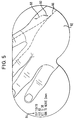
- FIG. 5 is a pictorial view of a patients hand as seen through one embodiment of the disclosed visual information system.
- a much better solution is to superimpose the image on the object being viewed, in effect highlighting the features of interest in the object.
- the vision enhancement imaging system disclosed for example, three dimensional information from the images used to guide the surgical procedure discussed above could be used to generate enhanced images and projected into the line of sight of the surgeon to allow the surgeon to see the images without having to look away from the patient.
- Figure 1 shows a schematic view of one embodiment of the disclosed imaging system.
- the video camera 22 monitors the subject, in this case a surgery patient, and transmits an electronic representation of the image to the processor 28 via channel 34 .
- the choice of video camera depends on the information required and is not critical to the invention.
- the camera could be monochrome or color, digital or analog, and could be receptive to light outside the visible spectrum.
- Optional patient position sensor 24 transmits information to the processor 28 to allow the image processing and display functions to compensate for patient motion.
- the object position and motion information can be extracted from the image obtained via the camera and the use of vision algorithms.
- the processor 28 may determine position and motion information by tracking features of the patient. If no suitable features exist naturally on the patient, high contrast marks could be drawn on the patient prior to beginning a procedure to allow the patient to be tracked optically by the processor 28 .
- Viewer position sensor 26 tracks the position of the viewer to allow the viewer to move or turn to see different views of an image. Not only does the position sensor 26 allow the processor 28 to compensate for the viewing angle, it allows the processor 28 to scale the image as the distance from the object to the viewer changes and to move the image across the screen as the viewer scans the object. If the initial positions of the viewer and object are known, then motion sensors may be used instead of position sensors. Motion compensation prevents images from being warped or smeared as the patient moves.
- the processor 28 applies image processing algorithms to manipulate the image from the camera 22 and other image sources.
- the other sources are not shown in Figure 1, but could include scanned photographs, MRI or CAT scans, other medical diagnostic equipment, prior surgical procedures, or any image device.
- Image processing functions that would be desirable in some applications are image conditioning, feature extraction, and matching or correlation algorithms.
- the computer generated images may be wire-frame representations or fully rendered three-dimensional images or a hybrid combination of the two. For example, a tumor may be fully rendered and colorized while the surrounding tissue is represented by a wire-frame model.
- the processor could also use false coloring to highlight certain features or objects. Textual data may also be displayed to inform the surgeon of the patients vital signs, duration of surgery, etc.
- the processor 28 may also receive inputs from the surgeon to allow the surgeon to mark areas of interest and to build a graphical database for later analysis. Inputs from the surgeon could also be used with stored information to aid feature recognition. The surgeon could use any available means to input data into the processor including a keyboard, mouse, touch screen, trackball, light pen, or voice recognition.
- Processor 28 can be any type of processor or group of processors capable of performing the necessary image processing and display control functions required of the imaging system.
- the processor could be designed around the Texas Instruments Multimedia Video Processor (MVP) image processing chip.
- MVP Texas Instruments Multimedia Video Processor
- the processor should have sufficient through-put to process the images, object motion, viewer position, and viewer input data in real-time.
- the required frame rate will vary depending on the application but should preferably be in the range of 60 to 100 frames per second, although 30 or fewer frames per second may be acceptable in some circumstances, especially situations with very little movement.
- the frame rate may be dynamically varied as image complexity and image processing algorithms vary the demands on processing power.
- the processed images are sent to the display device 30 via display control bus 40.
- the display device could be any type of spatial light modulator capable of displaying an image such that it appears superimposed on an object being viewed.
- Optics 33 are used as required to focus and project the image.
- Light source 32 and optics 33 may not be required in all applications depending on the type of spatial light modulator used.
- FIG. 1 One embodiment of a display system 68 comprising the display device, light-source, and optics is shown in Figure 2.
- Light from source 54 is focused and collimated as necessary by lens 58.
- the focused light 56 is modulated by a spatial light modulator, in this case a DMD array 60 .
- the reflected light 62 is focused and magnified as necessary by lens 64 .
- the light is then reflected off of the lens 50.
- light 48 from the object 46 is allowed to pass through the lens 50.
- the light 52 from the object and the DMD array exits the display system 68 and is seen by the viewer.
- the lens 50 may be worn like a pair of goggles, or a face shield, to allow the viewer to see the object 46 through the lens 50 and also see the image projected onto the lens.
- Lens 50 may be partially silvered to reflect light or may simply be any material with a partially reflective surface.
- Lens 50 is typically designed to allow approximately 90% of the light from the object to pass through the lens 50 while reflecting 10% of the reflected light 66 from the DMD.
- the amount of light reflected and transmitted by lens 50 depends on the application and the amount of light available from the object and the imager.
- the DMD 60 is particularly useful for this applications because it allows the brightness of the projected image to be adjusted over a wide range. This wide adjustment allows the viewer to strike an acceptable balance between image brightness and object visibility.
- a second embodiment of a display system according to the present invention simply attenuates light from the object of interest.
- This second embodiment shown in Figure 3, may use a liquid crystal display (LCD) instead of a DMD.
- LCD liquid crystal display
- the LCD 67 may be the actual lens of the goggles 69 worn by the viewer.
- Cable 71 carries the signals necessary to operate the LCD.
- the use of an LCD instead of the reflective lens of Figure 2 attenuates more of the light from the image and reduces the visibility of the viewer. Areas of interest may be marked by attenuating light from the areas of interest, or by attenuating light from all areas except those of interest.
- FIG. 4 A pictorial view of one embodiment of the surgical imaging system is shown in Figure 4.
- Viewer 72 looks though display system 68 at the object 46.
- both the display system 68 and the viewer position sensor 26 are head mounted on the viewer 72 .
- Object position sensor 24 is attached to the object 46 without obstructing the view of either the viewer 72 or the camera 22 .
- Processor 28 receives data from the camera 22 , the viewer position sensor 26 , and the object position sensor 24 and sends data to the display system 68.
- Figure 5 shows one example of the view through the imaging system during an operation to remove a foreign object from a patient.
- a surgeon is attempting to remove a foreign object 80 from a patient's hand 82.
- Textual information 84 such as the patient's vital signs, distances between objects, and elapsed time may be displayed.
- Objects of concern in this case a nerve 86 that the surgeon is attempting to avoid, and the entrance path 88 of the object 80, may be highlighted. It should be appreciated that as the surgeon moves in relation to the patient, the perspective of the displayed image and the patient's hand will change in unison allowing the surgeon to determine the best method of removing the object 80 .
Abstract
A visual information system to capture an input image using a camera 22, manipulate the image using processor 28, and project the processed image using optics 33 to superimpose the processed image on the actual object being observed by a viewer. Processing is done in real-time to allow the viewer to see both the actual and processed images while the viewer moves and changes viewing angles. Areas of interest in the displayed image may be highlighted or include graphical information for the viewer.
Description
- This invention relates to the field of image processing systems, more particularly to head-mounted image processing and display systems.
- There are many instances when it is advantageous to use photographs or electronically stored images to aid a viewer in observing the features and spatial relationships of an object. The features the viewer would like to locate or see are sometimes obscured or are difficult to locate with the unaided eye.
- One example is during a surgical procedure. A surgeon may take a photograph or an electronic image of an area before surgery begins. The image may be from previous diagnostic test such as magnetic resonance imaging (MRI) or computerized axial tomography (CAT). The surgeon will refer to this image during surgery as a guide for the procedure. For example, an image may be taken of a tumor before starting a removal procedure. During the procedure, the surgeon can refer back to the image to assist in locating the tumor or to ensure that the entire tumor has been removed.
- The present invention provides a method and device for providing visual information to a viewer without blocking the vision of the viewer or requiring the viewer to look away from the object of interest. One embodiment of the invention to provides an imaging system that displays a computer generated image in the field of view of the user, without obstructing the view of the user. This allows the user to see the image without looking away from the object of interest. Furthermore, the image the user sees will be manipulated to have the correct perspective or viewpoint. The computer generated image may be superimposed on the actual image that the user sees to help the user correlate information from the computer generated image with the users actual view of the object.
- It is a further advantage of the invention that the movement of the user or object can be monitored by the system and the displayed images changed to compensate for the movement. This allows the user to see the object from different perspectives by simply moving his head. This three dimensional effect is important in that the image may show internal features that may not be visible by the user. For example, during a surgical procedure locations of major arteries can be marked to allow the surgeon to avoid them.
- FIG. 1 is a schematic view of one embodiment of a visual information system.
- FIG. 2 is a schematic view of a first embodiment of a display mechanism of the visual information system.
- FIG. 3 is a pictorial view of a second embodiment of a display mechanism of the visual information system.
- FIG. 4 is a pictorial view of one embodiment of the visual information system.
- FIG. 5 is a pictorial view of a patients hand as seen through one embodiment of the disclosed visual information system.
- There are several drawbacks associated with using stored images to assist a viewer in identifying objects in his view. First, the viewer must look away from the object of interest in order to see the stored images, interrupting the work being performed and breaking the viewers concentration. Second, the images presented to the viewer have a fixed perspective, that is the viewer cannot usually manipulate the viewpoint of the image. Depending on the circumstances, the image may be difficult to correlate with the prespective of the viewer. For example, when testing an electronic assembly, the image of a component to be probed or removed may not be of much help when the component is surrounded by a large number of very similar, or worse yet, identical components.
- A much better solution is to superimpose the image on the object being viewed, in effect highlighting the features of interest in the object. There are many applications for the vision enhancement imaging system disclosed, for example, three dimensional information from the images used to guide the surgical procedure discussed above could be used to generate enhanced images and projected into the line of sight of the surgeon to allow the surgeon to see the images without having to look away from the patient.
- Figure 1 shows a schematic view of one embodiment of the disclosed imaging system. The
video camera 22 monitors the subject, in this case a surgery patient, and transmits an electronic representation of the image to theprocessor 28 via channel 34. The choice of video camera depends on the information required and is not critical to the invention. For example, the camera could be monochrome or color, digital or analog, and could be receptive to light outside the visible spectrum. In some applications it may be advantageous to have more than one camera to provide the processor with additional perspectives to aid in the generation of three-dimensional images. - Optional
patient position sensor 24 transmits information to theprocessor 28 to allow the image processing and display functions to compensate for patient motion. Note that the object position and motion information can be extracted from the image obtained via the camera and the use of vision algorithms. Theprocessor 28 may determine position and motion information by tracking features of the patient. If no suitable features exist naturally on the patient, high contrast marks could be drawn on the patient prior to beginning a procedure to allow the patient to be tracked optically by theprocessor 28. -
Viewer position sensor 26 tracks the position of the viewer to allow the viewer to move or turn to see different views of an image. Not only does theposition sensor 26 allow theprocessor 28 to compensate for the viewing angle, it allows theprocessor 28 to scale the image as the distance from the object to the viewer changes and to move the image across the screen as the viewer scans the object. If the initial positions of the viewer and object are known, then motion sensors may be used instead of position sensors. Motion compensation prevents images from being warped or smeared as the patient moves. - The
processor 28 applies image processing algorithms to manipulate the image from thecamera 22 and other image sources. The other sources are not shown in Figure 1, but could include scanned photographs, MRI or CAT scans, other medical diagnostic equipment, prior surgical procedures, or any image device. Image processing functions that would be desirable in some applications are image conditioning, feature extraction, and matching or correlation algorithms. The computer generated images may be wire-frame representations or fully rendered three-dimensional images or a hybrid combination of the two. For example, a tumor may be fully rendered and colorized while the surrounding tissue is represented by a wire-frame model. The processor could also use false coloring to highlight certain features or objects. Textual data may also be displayed to inform the surgeon of the patients vital signs, duration of surgery, etc. - In addition to manipulating the image data, the
processor 28 may also receive inputs from the surgeon to allow the surgeon to mark areas of interest and to build a graphical database for later analysis. Inputs from the surgeon could also be used with stored information to aid feature recognition. The surgeon could use any available means to input data into the processor including a keyboard, mouse, touch screen, trackball, light pen, or voice recognition. -
Processor 28 can be any type of processor or group of processors capable of performing the necessary image processing and display control functions required of the imaging system. For example, the processor could be designed around the Texas Instruments Multimedia Video Processor (MVP) image processing chip. The processor should have sufficient through-put to process the images, object motion, viewer position, and viewer input data in real-time. The required frame rate will vary depending on the application but should preferably be in the range of 60 to 100 frames per second, although 30 or fewer frames per second may be acceptable in some circumstances, especially situations with very little movement. The frame rate may be dynamically varied as image complexity and image processing algorithms vary the demands on processing power. - The processed images are sent to the display device 30 via
display control bus 40. The display device could be any type of spatial light modulator capable of displaying an image such that it appears superimposed on an object being viewed. Optics 33 are used as required to focus and project the image. Light source 32 and optics 33 may not be required in all applications depending on the type of spatial light modulator used. - One embodiment of a
display system 68 comprising the display device, light-source, and optics is shown in Figure 2. Light from source 54 is focused and collimated as necessary bylens 58. Thefocused light 56 is modulated by a spatial light modulator, in this case a DMD array 60. The reflectedlight 62 is focused and magnified as necessary by lens 64. The light is then reflected off of thelens 50. At the same time, light 48 from theobject 46 is allowed to pass through thelens 50. The light 52 from the object and the DMD array exits thedisplay system 68 and is seen by the viewer. - The
lens 50 may be worn like a pair of goggles, or a face shield, to allow the viewer to see theobject 46 through thelens 50 and also see the image projected onto the lens.Lens 50 may be partially silvered to reflect light or may simply be any material with a partially reflective surface.Lens 50 is typically designed to allow approximately 90% of the light from the object to pass through thelens 50 while reflecting 10% of the reflected light 66 from the DMD. The amount of light reflected and transmitted bylens 50 depends on the application and the amount of light available from the object and the imager. The DMD 60 is particularly useful for this applications because it allows the brightness of the projected image to be adjusted over a wide range. This wide adjustment allows the viewer to strike an acceptable balance between image brightness and object visibility. - A second embodiment of a display system according to the present invention simply attenuates light from the object of interest. This second embodiment, shown in Figure 3, may use a liquid crystal display (LCD) instead of a DMD. Because no light source or projection optics are required, the
LCD 67 may be the actual lens of thegoggles 69 worn by the viewer.Cable 71 carries the signals necessary to operate the LCD. The use of an LCD instead of the reflective lens of Figure 2 attenuates more of the light from the image and reduces the visibility of the viewer. Areas of interest may be marked by attenuating light from the areas of interest, or by attenuating light from all areas except those of interest. - A pictorial view of one embodiment of the surgical imaging system is shown in Figure 4.
Viewer 72 looks thoughdisplay system 68 at theobject 46. In this embodiment both thedisplay system 68 and theviewer position sensor 26 are head mounted on theviewer 72.Object position sensor 24 is attached to theobject 46 without obstructing the view of either theviewer 72 or thecamera 22.Processor 28 receives data from thecamera 22, theviewer position sensor 26, and theobject position sensor 24 and sends data to thedisplay system 68. - Figure 5 shows one example of the view through the imaging system during an operation to remove a foreign object from a patient. In Figure 5 a surgeon is attempting to remove a
foreign object 80 from a patient'shand 82.Textual information 84, such as the patient's vital signs, distances between objects, and elapsed time may be displayed. Objects of concern, in this case anerve 86 that the surgeon is attempting to avoid, and theentrance path 88 of theobject 80, may be highlighted. It should be appreciated that as the surgeon moves in relation to the patient, the perspective of the displayed image and the patient's hand will change in unison allowing the surgeon to determine the best method of removing theobject 80. - Thus, although there has been disclosed to this point a particular embodiment for a surgical imaging system, it is not intended that such specific references be considered as limitations upon the scope of this invention except in-so-far as set forth in the following claims. Furthermore, having described the invention in connection with certain specific embodiments thereof, it is to be understood that further modifications may now suggest themselves to those skilled in the art, it is intended to cover all such modifications as fall within the scope of the appended claims.
Claims (21)
- An imaging system comprising:
a camera to monitor a scene in order to convert scene information into electronic signals, and to transmit said signals;
a processor to receive said signals from said camera, and to perform image processing routines on said signals, and to generate processed signals representing information about said scene; and
a display device to receive said processed signals and to convert said processed signals into a displayed image, wherein a viewer may look through said display device and see both said scene and said displayed image. - The imaging system of claim 1, wherein said displayed image is superimposed on said scene from the perspective of said viewer.
- The imaging system of claim 1, wherein said displayed image is projected onto the lens of a pair of goggles.
- The imaging system of claim 1, wherein said displayed image is projected onto a face shield.
- The imaging system of claim 1 wherein said display device comprises a spatial light modulator, wherein said viewer looks through said spatial light modulator.
- The imaging system of claim 1 wherein said display device comprises a digital micromirror device.
- The imaging system of claim 1 wherein said display device comprises a liquid crystal display.
- The imaging system of claim 1 wherein said display device comprises a partially silvered lens.
- The imaging system of claim 1, wherein said display devil is head-mounted on the user of said system.
- The imaging system of claim 1, wherein said processor performs said image processing routines in real-time.
- The imaging system of claim 1, wherein said processor tracks features of said scene such that motion in said scene is compensated.
- The imaging system of claim 1, further comprising a position sensor attached to an object in said scene and in communication with said processor to allow said processor to monitor the position of said object in said scene.
- The imaging system of claim 1, further comprising a motion sensor attached to an object in said scene and in communication with said processor to allow said processor to compensate for motion of said object within said scene.
- The imaging system of claim 1, further comprising a position sensor attached to said user and in communication with said processor to allow said processor to compensate for movement of said user.
- The imaging system of claim 1, further comprising a motion sensor attached to said user and in communication with said processor to allow said processor to compensate for movement of said user.
- The imaging system of claim 1, wherein said displayed image is a high-contrast picture of said scene.
- The imaging system of claim 1, wherein said displayed image is a false-color representation of a portion of said scene.
- An imaging system comprising:
a camera to constantly monitor a scene and convert scene information to electronic signals;
a processor to receive said electronic signals and perform image processing routines on said electronic signals and to output a processed video signal;
a position sensor attached to an object in said scene to communicate information concerning the position of said object to said processor;
a position sensor attached to a user of said system to communicate information concerning the position of said user to said processor;
a display device to receive said video signal and to convert said video signal into a display image, wherein a viewer may look through said display device and see the display image superimposed on said scene. - A method of displaying an image of an object comprising:
converting light from an object to electronic signals using a camera;
tracking the position of said object;
tracking the position of a viewer;
processing said electronic signals to compensate for the relative position of said object and said viewer;
converting said processed electronic signals into an image; and
displaying said image such that said viewer sees said image superimposed on said object. - The method of claim 15 wherein tracking the position of said object using a position sensor is replaced with tracking the motion of said object with a motion sensor.
- The method of claim 15 wherein tracking the position of said viewer using a position sensor is replaced with tracking the motion of said viewer with a motion sensor.
Applications Claiming Priority (2)
| Application Number | Priority Date | Filing Date | Title |
|---|---|---|---|
| US08/161,831 US5491510A (en) | 1993-12-03 | 1993-12-03 | System and method for simultaneously viewing a scene and an obscured object |
| US161831 | 1993-12-03 |
Publications (2)
| Publication Number | Publication Date |
|---|---|
| EP0665686A2 true EP0665686A2 (en) | 1995-08-02 |
| EP0665686A3 EP0665686A3 (en) | 1998-03-18 |
Family
ID=22582934
Family Applications (1)
| Application Number | Title | Priority Date | Filing Date |
|---|---|---|---|
| EP94119066A Withdrawn EP0665686A3 (en) | 1993-12-03 | 1994-12-02 | Visual information system |
Country Status (7)
| Country | Link |
|---|---|
| US (1) | US5491510A (en) |
| EP (1) | EP0665686A3 (en) |
| JP (1) | JP3618381B2 (en) |
| KR (1) | KR950016661A (en) |
| CN (1) | CN1056259C (en) |
| CA (1) | CA2137057A1 (en) |
| TW (1) | TW346581B (en) |
Cited By (12)
| Publication number | Priority date | Publication date | Assignee | Title |
|---|---|---|---|---|
| WO1996036271A1 (en) * | 1995-05-15 | 1996-11-21 | Leica Ag | Process and device for the parallel capture of visual information |
| EP0830836A1 (en) * | 1996-09-13 | 1998-03-25 | Colin Corporation | Physical-information-image displaying apparatus |
| WO1999049656A1 (en) * | 1998-03-25 | 1999-09-30 | Mann W Stephen G | Wearable camera system with viewfinder means |
| US6020917A (en) * | 1994-03-29 | 2000-02-01 | Laser Surge, Inc. | Video display system for locating a projected image adjacent a surgical field |
| US6023289A (en) * | 1994-03-29 | 2000-02-08 | Laser Surge, Inc. | Video display system for locating a projected image adjacent a surgical field |
| US6253032B1 (en) | 1998-11-18 | 2001-06-26 | U.S. Philips Corporation | Studio camera viewfinder |
| US6307526B1 (en) | 1998-02-02 | 2001-10-23 | W. Steve G. Mann | Wearable camera system with viewfinder means |
| EP1304853A3 (en) * | 2001-10-18 | 2003-07-30 | Nokia Corporation | Method and hand-held device for obtaining an image of an object by combining a plurality of images |
| US6614408B1 (en) | 1998-03-25 | 2003-09-02 | W. Stephen G. Mann | Eye-tap for electronic newsgathering, documentary video, photojournalism, and personal safety |
| EP1415609A1 (en) * | 1998-01-28 | 2004-05-06 | Sherwood Services AG | Optical object tracking system |
| EP2628460A3 (en) * | 2007-08-14 | 2017-06-28 | Koninklijke Philips N.V. | Robotic instrument systems and methods utilizing optical fiber sensors |
| US10728519B2 (en) | 2004-06-17 | 2020-07-28 | Align Technology, Inc. | Method and apparatus for colour imaging a three-dimensional structure |
Families Citing this family (169)
| Publication number | Priority date | Publication date | Assignee | Title |
|---|---|---|---|---|
| US6417969B1 (en) | 1988-07-01 | 2002-07-09 | Deluca Michael | Multiple viewer headset display apparatus and method with second person icon display |
| US6219015B1 (en) | 1992-04-28 | 2001-04-17 | The Board Of Directors Of The Leland Stanford, Junior University | Method and apparatus for using an array of grating light valves to produce multicolor optical images |
| US5694142A (en) * | 1993-06-21 | 1997-12-02 | General Electric Company | Interactive digital arrow (d'arrow) three-dimensional (3D) pointing |
| US20010054989A1 (en) * | 1993-10-22 | 2001-12-27 | Matthew Zavracky | Color sequential display panels |
| US7310072B2 (en) * | 1993-10-22 | 2007-12-18 | Kopin Corporation | Portable communication display device |
| DE4344050C1 (en) * | 1993-12-23 | 1995-03-09 | Henry Rudolph | Entry method and entry apparatus for computer terminals for the purpose of protecting against covert observation and for ensuring the privacy of a user |
| US5642129A (en) * | 1994-03-23 | 1997-06-24 | Kopin Corporation | Color sequential display panels |
| US6097352A (en) * | 1994-03-23 | 2000-08-01 | Kopin Corporation | Color sequential display panels |
| JPH086708A (en) * | 1994-04-22 | 1996-01-12 | Canon Inc | Display device |
| DE4417944A1 (en) * | 1994-05-21 | 1995-11-23 | Zeiss Carl Fa | Process for correlating different coordinate systems in computer-assisted, stereotactic surgery |
| US5765561A (en) * | 1994-10-07 | 1998-06-16 | Medical Media Systems | Video-based surgical targeting system |
| JPH08242417A (en) * | 1995-03-01 | 1996-09-17 | Olympus Optical Co Ltd | Information reproduction system and information recording medium |
| US5841409A (en) * | 1995-04-18 | 1998-11-24 | Minolta Co., Ltd. | Image display apparatus |
| US5717414A (en) * | 1995-05-01 | 1998-02-10 | Lockheed-Martin Tactical Defense Systems | Video image tracking and mixing system |
| US6151404A (en) * | 1995-06-01 | 2000-11-21 | Medical Media Systems | Anatomical visualization system |
| US5737506A (en) * | 1995-06-01 | 1998-04-07 | Medical Media Systems | Anatomical visualization system |
| US5841579A (en) | 1995-06-07 | 1998-11-24 | Silicon Light Machines | Flat diffraction grating light valve |
| US5905525A (en) * | 1995-07-13 | 1999-05-18 | Minolta Co., Ltd. | Image display apparatus having a display controlled by user's head movement |
| US5776050A (en) * | 1995-07-24 | 1998-07-07 | Medical Media Systems | Anatomical visualization system |
| US6702736B2 (en) * | 1995-07-24 | 2004-03-09 | David T. Chen | Anatomical visualization system |
| JP3141737B2 (en) * | 1995-08-10 | 2001-03-05 | 株式会社セガ | Virtual image generation apparatus and method |
| US5742263A (en) * | 1995-12-18 | 1998-04-21 | Telxon Corporation | Head tracking system for a head mounted display system |
| US5825908A (en) * | 1995-12-29 | 1998-10-20 | Medical Media Systems | Anatomical visualization and measurement system |
| US5812101A (en) * | 1996-04-04 | 1998-09-22 | Northrop Grumman Corporation | High performance, low cost helmet mounted display |
| US6167296A (en) * | 1996-06-28 | 2000-12-26 | The Board Of Trustees Of The Leland Stanford Junior University | Method for volumetric image navigation |
| US6046712A (en) * | 1996-07-23 | 2000-04-04 | Telxon Corporation | Head mounted communication system for providing interactive visual communications with a remote system |
| JP3387326B2 (en) | 1996-08-30 | 2003-03-17 | ミノルタ株式会社 | Video observation system |
| JP3338618B2 (en) * | 1996-10-07 | 2002-10-28 | ミノルタ株式会社 | Display method and display device for real space image and virtual space image |
| US6204974B1 (en) | 1996-10-08 | 2001-03-20 | The Microoptical Corporation | Compact image display system for eyeglasses or other head-borne frames |
| US5886822A (en) * | 1996-10-08 | 1999-03-23 | The Microoptical Corporation | Image combining system for eyeglasses and face masks |
| US6023372A (en) * | 1997-10-30 | 2000-02-08 | The Microoptical Corporation | Light weight, compact remountable electronic display device for eyeglasses or other head-borne eyewear frames |
| US6069608A (en) * | 1996-12-03 | 2000-05-30 | Sony Corporation | Display device having perception image for improving depth perception of a virtual image |
| JPH10191142A (en) * | 1996-12-20 | 1998-07-21 | Nikon Corp | Image processor |
| WO1998032388A2 (en) * | 1997-01-24 | 1998-07-30 | Koninklijke Philips Electronics N.V. | Image display system |
| US6091767A (en) * | 1997-02-03 | 2000-07-18 | Westerman; Larry Alan | System for improving efficiency of video encoders |
| US5982553A (en) | 1997-03-20 | 1999-11-09 | Silicon Light Machines | Display device incorporating one-dimensional grating light-valve array |
| US5953000A (en) * | 1997-06-02 | 1999-09-14 | Weirich; John P. | Bounded-display-surface system for the input and output of computer data and video graphics |
| JP3052286B2 (en) * | 1997-08-28 | 2000-06-12 | 防衛庁技術研究本部長 | Flight system and pseudo visual field forming device for aircraft |
| KR19990030882A (en) * | 1997-10-07 | 1999-05-06 | 이해규 | Digital still camera with adjustable focus position and its control method |
| EP1027627B1 (en) * | 1997-10-30 | 2009-02-11 | MYVU Corporation | Eyeglass interface system |
| US6088102A (en) | 1997-10-31 | 2000-07-11 | Silicon Light Machines | Display apparatus including grating light-valve array and interferometric optical system |
| US6611618B1 (en) * | 1997-11-13 | 2003-08-26 | Schepens Eye Research Institute, Inc. | Wide-band image enhancement |
| US5870136A (en) * | 1997-12-05 | 1999-02-09 | The University Of North Carolina At Chapel Hill | Dynamic generation of imperceptible structured light for tracking and acquisition of three dimensional scene geometry and surface characteristics in interactive three dimensional computer graphics applications |
| US6271808B1 (en) | 1998-06-05 | 2001-08-07 | Silicon Light Machines | Stereo head mounted display using a single display device |
| US6130770A (en) | 1998-06-23 | 2000-10-10 | Silicon Light Machines | Electron gun activated grating light valve |
| US6101036A (en) | 1998-06-23 | 2000-08-08 | Silicon Light Machines | Embossed diffraction grating alone and in combination with changeable image display |
| US6215579B1 (en) | 1998-06-24 | 2001-04-10 | Silicon Light Machines | Method and apparatus for modulating an incident light beam for forming a two-dimensional image |
| US6064354A (en) | 1998-07-01 | 2000-05-16 | Deluca; Michael Joseph | Stereoscopic user interface method and apparatus |
| US6303986B1 (en) | 1998-07-29 | 2001-10-16 | Silicon Light Machines | Method of and apparatus for sealing an hermetic lid to a semiconductor die |
| CA2363138C (en) * | 1999-03-01 | 2010-05-18 | Bae Systems Electronics Limited | Head tracker system |
| US6503195B1 (en) | 1999-05-24 | 2003-01-07 | University Of North Carolina At Chapel Hill | Methods and systems for real-time structured light depth extraction and endoscope using real-time structured light depth extraction |
| US6724354B1 (en) | 1999-06-21 | 2004-04-20 | The Microoptical Corporation | Illumination systems for eyeglass and facemask display systems |
| US7158096B1 (en) | 1999-06-21 | 2007-01-02 | The Microoptical Corporation | Compact, head-mountable display device with suspended eyepiece assembly |
| DE60006535T2 (en) | 1999-06-21 | 2004-09-23 | The Microoptical Corp., Westwood | DISPLAY DEVICE WITH OKULAR, DISPLAY AND LIGHTING DEVICE ON OPTOMECHANICAL CARRIER |
| US6353503B1 (en) | 1999-06-21 | 2002-03-05 | The Micropitical Corporation | Eyeglass display lens system employing off-axis optical design |
| US6583792B1 (en) * | 1999-11-09 | 2003-06-24 | Newag Digital, Llc | System and method for accurately displaying superimposed images |
| JP3833099B2 (en) * | 2000-11-17 | 2006-10-11 | キヤノン株式会社 | Control device and control method for game machine, and computer-readable control program |
| US6690960B2 (en) * | 2000-12-21 | 2004-02-10 | David T. Chen | Video-based surgical targeting system |
| EP1372516B1 (en) * | 2001-02-27 | 2009-05-13 | Smith & Nephew, Inc. | Surgical navigation systems for unicompartmental knee |
| US20050113846A1 (en) * | 2001-02-27 | 2005-05-26 | Carson Christopher P. | Surgical navigation systems and processes for unicompartmental knee arthroplasty |
| US7547307B2 (en) | 2001-02-27 | 2009-06-16 | Smith & Nephew, Inc. | Computer assisted knee arthroplasty instrumentation, systems, and processes |
| US6707591B2 (en) | 2001-04-10 | 2004-03-16 | Silicon Light Machines | Angled illumination for a single order light modulator based projection system |
| US6747781B2 (en) | 2001-06-25 | 2004-06-08 | Silicon Light Machines, Inc. | Method, apparatus, and diffuser for reducing laser speckle |
| US6782205B2 (en) | 2001-06-25 | 2004-08-24 | Silicon Light Machines | Method and apparatus for dynamic equalization in wavelength division multiplexing |
| US6829092B2 (en) | 2001-08-15 | 2004-12-07 | Silicon Light Machines, Inc. | Blazed grating light valve |
| US6785001B2 (en) * | 2001-08-21 | 2004-08-31 | Silicon Light Machines, Inc. | Method and apparatus for measuring wavelength jitter of light signal |
| WO2003023756A1 (en) * | 2001-09-07 | 2003-03-20 | The Microoptical Corporation | Light weight, compact, remountable face-supported electronic display |
| US7313246B2 (en) * | 2001-10-06 | 2007-12-25 | Stryker Corporation | Information system using eyewear for communication |
| WO2003034705A2 (en) * | 2001-10-19 | 2003-04-24 | University Of North Carolina At Chapel Hill | Methods and systems for dynamic virtual convergence and head mountable display |
| US20030107648A1 (en) * | 2001-12-12 | 2003-06-12 | Richard Stewart | Surveillance system and method with adaptive frame rate |
| US6800238B1 (en) | 2002-01-15 | 2004-10-05 | Silicon Light Machines, Inc. | Method for domain patterning in low coercive field ferroelectrics |
| CA2475979A1 (en) | 2002-02-11 | 2003-08-21 | Smith & Nephew, Inc. | Image-guided fracture reduction |
| US6917370B2 (en) * | 2002-05-13 | 2005-07-12 | Charles Benton | Interacting augmented reality and virtual reality |
| US6767751B2 (en) | 2002-05-28 | 2004-07-27 | Silicon Light Machines, Inc. | Integrated driver process flow |
| US6728023B1 (en) | 2002-05-28 | 2004-04-27 | Silicon Light Machines | Optical device arrays with optimized image resolution |
| US6822797B1 (en) | 2002-05-31 | 2004-11-23 | Silicon Light Machines, Inc. | Light modulator structure for producing high-contrast operation using zero-order light |
| US7385708B2 (en) * | 2002-06-07 | 2008-06-10 | The University Of North Carolina At Chapel Hill | Methods and systems for laser based real-time structured light depth extraction |
| US6829258B1 (en) | 2002-06-26 | 2004-12-07 | Silicon Light Machines, Inc. | Rapidly tunable external cavity laser |
| US6813059B2 (en) | 2002-06-28 | 2004-11-02 | Silicon Light Machines, Inc. | Reduced formation of asperities in contact micro-structures |
| US6714337B1 (en) | 2002-06-28 | 2004-03-30 | Silicon Light Machines | Method and device for modulating a light beam and having an improved gamma response |
| US6801354B1 (en) | 2002-08-20 | 2004-10-05 | Silicon Light Machines, Inc. | 2-D diffraction grating for substantially eliminating polarization dependent losses |
| US6712480B1 (en) | 2002-09-27 | 2004-03-30 | Silicon Light Machines | Controlled curvature of stressed micro-structures |
| US7693702B1 (en) * | 2002-11-01 | 2010-04-06 | Lockheed Martin Corporation | Visualizing space systems modeling using augmented reality |
| DE10251933B4 (en) * | 2002-11-08 | 2006-12-14 | Ludwig-Maximilians-Universität München (Körperschaft des öffentlichen Rechts) | Recording device for the head-based image acquisition and method for controlling the recording device |
| US20040095311A1 (en) * | 2002-11-19 | 2004-05-20 | Motorola, Inc. | Body-centric virtual interactive apparatus and method |
| US7111401B2 (en) * | 2003-02-04 | 2006-09-26 | Eveready Battery Company, Inc. | Razor head having skin controlling means |
| US6829077B1 (en) | 2003-02-28 | 2004-12-07 | Silicon Light Machines, Inc. | Diffractive light modulator with dynamically rotatable diffraction plane |
| US6806997B1 (en) | 2003-02-28 | 2004-10-19 | Silicon Light Machines, Inc. | Patterned diffractive light modulator ribbon for PDL reduction |
| US7063256B2 (en) * | 2003-03-04 | 2006-06-20 | United Parcel Service Of America | Item tracking and processing systems and methods |
| WO2004079546A2 (en) * | 2003-03-04 | 2004-09-16 | United Parcel Service Of America, Inc. | System for projecting a handling instruction onto a moving item or parcel |
| US20040233192A1 (en) * | 2003-05-22 | 2004-11-25 | Hopper Stephen A. | Focally-controlled imaging system and method |
| US7862570B2 (en) | 2003-10-03 | 2011-01-04 | Smith & Nephew, Inc. | Surgical positioners |
| US7764985B2 (en) * | 2003-10-20 | 2010-07-27 | Smith & Nephew, Inc. | Surgical navigation system component fault interfaces and related processes |
| US20050085822A1 (en) * | 2003-10-20 | 2005-04-21 | Thornberry Robert C. | Surgical navigation system component fault interfaces and related processes |
| US7197170B2 (en) * | 2003-11-10 | 2007-03-27 | M2S, Inc. | Anatomical visualization and measurement system |
| DE602004031147D1 (en) | 2003-11-14 | 2011-03-03 | Smith & Nephew Inc | |
| WO2005053559A1 (en) * | 2003-11-25 | 2005-06-16 | Smith & Nephew, Inc. | Methods and apparatuses for providing a navigational array |
| US20050113659A1 (en) * | 2003-11-26 | 2005-05-26 | Albert Pothier | Device for data input for surgical navigation system |
| US8363144B2 (en) * | 2003-12-18 | 2013-01-29 | Anthrotronix, Inc. | Operator control unit with tracking |
| US7567282B2 (en) * | 2003-12-18 | 2009-07-28 | Anthrotronix, Inc. | Operator control unit with tracking |
| JP2007523696A (en) * | 2004-01-16 | 2007-08-23 | スミス アンド ネフュー インコーポレーテッド | Computer-aided ligament balancing in total knee arthroplasty |
| US20050159759A1 (en) * | 2004-01-20 | 2005-07-21 | Mark Harbaugh | Systems and methods for performing minimally invasive incisions |
| US20050197569A1 (en) * | 2004-01-22 | 2005-09-08 | Mccombs Daniel | Methods, systems, and apparatuses for providing patient-mounted surgical navigational sensors |
| US20060036162A1 (en) * | 2004-02-02 | 2006-02-16 | Ramin Shahidi | Method and apparatus for guiding a medical instrument to a subsurface target site in a patient |
| US7182465B2 (en) * | 2004-02-25 | 2007-02-27 | The University Of North Carolina | Methods, systems, and computer program products for imperceptibly embedding structured light patterns in projected color images for display on planar and non-planar surfaces |
| US20060098010A1 (en) * | 2004-03-09 | 2006-05-11 | Jeff Dwyer | Anatomical visualization and measurement system |
| WO2005096982A1 (en) * | 2004-03-31 | 2005-10-20 | Smith & Nephew, Inc. | Methods and apparatuses for providing a reference array input device |
| US20050234466A1 (en) * | 2004-03-31 | 2005-10-20 | Jody Stallings | TLS adjustable block |
| US20050234465A1 (en) * | 2004-03-31 | 2005-10-20 | Mccombs Daniel L | Guided saw with pins |
| US20050228404A1 (en) * | 2004-04-12 | 2005-10-13 | Dirk Vandevelde | Surgical navigation system component automated imaging navigation and related processes |
| JP4808704B2 (en) * | 2004-04-15 | 2011-11-02 | スミス アンド ネフュー インコーポレーテッド | Detachable and repositionable reference frame for computer-assisted surgery |
| US8109942B2 (en) * | 2004-04-21 | 2012-02-07 | Smith & Nephew, Inc. | Computer-aided methods, systems, and apparatuses for shoulder arthroplasty |
| US20050279368A1 (en) * | 2004-06-16 | 2005-12-22 | Mccombs Daniel L | Computer assisted surgery input/output systems and processes |
| US7561717B2 (en) * | 2004-07-09 | 2009-07-14 | United Parcel Service Of America, Inc. | System and method for displaying item information |
| WO2006020187A2 (en) * | 2004-07-16 | 2006-02-23 | The University Of North Carolina At Chapel Hill | Methods, systems and computer program products for full spectrum projection |
| US7702137B2 (en) | 2004-11-10 | 2010-04-20 | M2S, Inc. | Anatomical visualization and measurement system |
| AU2005311751A1 (en) * | 2004-12-02 | 2006-06-08 | Smith & Nephew, Inc. | Systems, methods, and apparatus for automatic software flow using instrument detection during computer-aided surgery |
| AU2005311752A1 (en) * | 2004-12-02 | 2006-06-08 | Smith & Nephew, Inc. | Systems for providing a reference plane for mounting an acetabular cup |
| US20060161051A1 (en) * | 2005-01-18 | 2006-07-20 | Lauralan Terrill-Grisoni | Method of computer-assisted ligament balancing and component placement in total knee arthroplasty |
| CA2601976A1 (en) | 2005-02-22 | 2006-08-31 | Smith & Nephew, Inc. | In-line milling system |
| US20070118055A1 (en) * | 2005-11-04 | 2007-05-24 | Smith & Nephew, Inc. | Systems and methods for facilitating surgical procedures involving custom medical implants |
| US20110057930A1 (en) * | 2006-07-26 | 2011-03-10 | Inneroptic Technology Inc. | System and method of using high-speed, high-resolution depth extraction to provide three-dimensional imagery for endoscopy |
| US7728868B2 (en) * | 2006-08-02 | 2010-06-01 | Inneroptic Technology, Inc. | System and method of providing real-time dynamic imagery of a medical procedure site using multiple modalities |
| US20080055194A1 (en) * | 2006-08-31 | 2008-03-06 | Motorola, Inc. | Method and system for context based user interface information presentation and positioning |
| US9883818B2 (en) | 2007-06-19 | 2018-02-06 | Accuray Incorporated | Fiducial localization |
| US20090003528A1 (en) | 2007-06-19 | 2009-01-01 | Sankaralingam Ramraj | Target location by tracking of imaging device |
| WO2009094646A2 (en) * | 2008-01-24 | 2009-07-30 | The University Of North Carolina At Chapel Hill | Methods, systems, and computer readable media for image guided ablation |
| US8340379B2 (en) | 2008-03-07 | 2012-12-25 | Inneroptic Technology, Inc. | Systems and methods for displaying guidance data based on updated deformable imaging data |
| US11464578B2 (en) | 2009-02-17 | 2022-10-11 | Inneroptic Technology, Inc. | Systems, methods, apparatuses, and computer-readable media for image management in image-guided medical procedures |
| US8641621B2 (en) | 2009-02-17 | 2014-02-04 | Inneroptic Technology, Inc. | Systems, methods, apparatuses, and computer-readable media for image management in image-guided medical procedures |
| US8554307B2 (en) | 2010-04-12 | 2013-10-08 | Inneroptic Technology, Inc. | Image annotation in image-guided medical procedures |
| US8690776B2 (en) * | 2009-02-17 | 2014-04-08 | Inneroptic Technology, Inc. | Systems, methods, apparatuses, and computer-readable media for image guided surgery |
| ES2823456T3 (en) | 2009-06-25 | 2021-05-07 | Univ North Carolina Chapel Hill | Method and System for Using Powered Surface Bonded Posts to Assess the Rheology of Biological Fluids |
| WO2011014687A2 (en) * | 2009-07-31 | 2011-02-03 | Inneroptic Technology, Inc. | Dual-tube stereoscope |
| US20110082351A1 (en) * | 2009-10-07 | 2011-04-07 | Inneroptic Technology, Inc. | Representing measurement information during a medical procedure |
| US9282947B2 (en) | 2009-12-01 | 2016-03-15 | Inneroptic Technology, Inc. | Imager focusing based on intraoperative data |
| JP5158062B2 (en) * | 2009-12-01 | 2013-03-06 | ブラザー工業株式会社 | Head mounted display |
| JP5530234B2 (en) * | 2010-03-29 | 2014-06-25 | オリンパス株式会社 | Operation input device and manipulator system |
| JP5579014B2 (en) * | 2010-10-12 | 2014-08-27 | キヤノン株式会社 | Video information processing apparatus and method |
| US20120157204A1 (en) * | 2010-12-20 | 2012-06-21 | Lai Games Australia Pty Ltd. | User-controlled projector-based games |
| EP2544039A1 (en) * | 2011-07-04 | 2013-01-09 | BAE Systems Plc. | Display system |
| US8670816B2 (en) | 2012-01-30 | 2014-03-11 | Inneroptic Technology, Inc. | Multiple medical device guidance |
| US9001005B2 (en) | 2012-02-29 | 2015-04-07 | Recon Instruments Inc. | Modular heads-up display systems |
| US9069166B2 (en) | 2012-02-29 | 2015-06-30 | Recon Instruments Inc. | Gaze detecting heads-up display systems |
| CN102779000B (en) * | 2012-05-03 | 2015-05-20 | 苏州触达信息技术有限公司 | User interaction system and method |
| CN104684398A (en) | 2012-08-31 | 2015-06-03 | 索隆-基特林癌症研究协会 | Particles, methods and uses thereof |
| US20140081659A1 (en) | 2012-09-17 | 2014-03-20 | Depuy Orthopaedics, Inc. | Systems and methods for surgical and interventional planning, support, post-operative follow-up, and functional recovery tracking |
| US9881383B2 (en) | 2013-01-28 | 2018-01-30 | Virtek Vision International Ulc | Laser projection system with motion compensation and method |
| JP6635791B2 (en) * | 2013-02-20 | 2020-01-29 | スローン − ケタリング・インスティテュート・フォー・キャンサー・リサーチ | Wide-field Raman imaging apparatus and related method |
| US10314559B2 (en) | 2013-03-14 | 2019-06-11 | Inneroptic Technology, Inc. | Medical device guidance |
| US10194860B2 (en) | 2013-09-11 | 2019-02-05 | Industrial Technology Research Institute | Virtual image display system |
| TWI518368B (en) * | 2013-09-11 | 2016-01-21 | 財團法人工業技術研究院 | Virtual image display apparatus |
| CN104706422A (en) * | 2013-12-13 | 2015-06-17 | Ge医疗系统环球技术有限公司 | Head-worn type medical device, medical system and operation method of medical system |
| US10912947B2 (en) | 2014-03-04 | 2021-02-09 | Memorial Sloan Kettering Cancer Center | Systems and methods for treatment of disease via application of mechanical force by controlled rotation of nanoparticles inside cells |
| US9677840B2 (en) | 2014-03-14 | 2017-06-13 | Lineweight Llc | Augmented reality simulator |
| US10460252B2 (en) | 2014-07-25 | 2019-10-29 | Raytheon Company | System and method of chaining algorithms for global object recognition to improve probability of correctness and reduce processing load |
| EP3180038A4 (en) | 2014-07-28 | 2018-04-04 | Memorial Sloan-Kettering Cancer Center | Metal(loid) chalcogen nanoparticles as universal binders for medical isotopes |
| US9901406B2 (en) | 2014-10-02 | 2018-02-27 | Inneroptic Technology, Inc. | Affected region display associated with a medical device |
| US10188467B2 (en) | 2014-12-12 | 2019-01-29 | Inneroptic Technology, Inc. | Surgical guidance intersection display |
| US10919089B2 (en) | 2015-07-01 | 2021-02-16 | Memorial Sloan Kettering Cancer Center | Anisotropic particles, methods and uses thereof |
| US9949700B2 (en) | 2015-07-22 | 2018-04-24 | Inneroptic Technology, Inc. | Medical device approaches |
| US9675319B1 (en) | 2016-02-17 | 2017-06-13 | Inneroptic Technology, Inc. | Loupe display |
| EP3531953A1 (en) * | 2016-10-25 | 2019-09-04 | Novartis AG | Medical spatial orientation system |
| US10278778B2 (en) | 2016-10-27 | 2019-05-07 | Inneroptic Technology, Inc. | Medical device navigation using a virtual 3D space |
| US10471478B2 (en) | 2017-04-28 | 2019-11-12 | United Parcel Service Of America, Inc. | Conveyor belt assembly for identifying an asset sort location and methods of utilizing the same |
| US11259879B2 (en) | 2017-08-01 | 2022-03-01 | Inneroptic Technology, Inc. | Selective transparency to assist medical device navigation |
| US11484365B2 (en) | 2018-01-23 | 2022-11-01 | Inneroptic Technology, Inc. | Medical image guidance |
| JP2020155923A (en) * | 2019-03-20 | 2020-09-24 | ソニー株式会社 | Remote control device, imaging control device and method thereof |
| US11741152B2 (en) | 2019-10-07 | 2023-08-29 | Raytheon Company | Object recognition and detection using reinforcement learning |
Citations (3)
| Publication number | Priority date | Publication date | Assignee | Title |
|---|---|---|---|---|
| EP0065578A1 (en) * | 1981-05-21 | 1982-12-01 | Harald Teinzer | Protective goggles or helmet with integral speed, time and altitude measuring means |
| EP0391529A2 (en) * | 1989-02-27 | 1990-10-10 | Texas Instruments Incorporated | Apparatus for digitized video system |
| DE9217643U1 (en) * | 1992-04-29 | 1993-06-03 | Siwoff, Ronald, Bridgewater, N.J., Us |
Family Cites Families (12)
| Publication number | Priority date | Publication date | Assignee | Title |
|---|---|---|---|---|
| US3170979A (en) * | 1962-04-30 | 1965-02-23 | Alan W Baldwin | Optical image interposing display device |
| JPS59117876A (en) * | 1982-12-24 | 1984-07-07 | Seiko Epson Corp | Personal liquid crystal video display device |
| GB2222923B (en) * | 1988-09-14 | 1992-09-23 | Marconi Gec Ltd | Display apparatus |
| US4961626A (en) * | 1989-02-21 | 1990-10-09 | United Techologies Corporation | Direct incorporation of night vision in a helmet mounted display |
| JPH03266573A (en) * | 1990-03-16 | 1991-11-27 | Hitachi Medical Corp | X ray picture input device |
| CA2060406C (en) * | 1991-04-22 | 1998-12-01 | Bruce Edward Hamilton | Helicopter virtual image display system incorporating structural outlines |
| US5227769A (en) * | 1991-05-23 | 1993-07-13 | Westinghouse Electric Corp. | Heads-up projection display |
| US5404293A (en) * | 1991-06-11 | 1995-04-04 | The University Of Utah | Cone beam reconstruction using helical data collection paths |
| US5222477A (en) * | 1991-09-30 | 1993-06-29 | Welch Allyn, Inc. | Endoscope or borescope stereo viewing system |
| US5303085A (en) * | 1992-02-07 | 1994-04-12 | Rallison Richard D | Optically corrected helmet mounted display |
| JPH05328260A (en) * | 1992-05-26 | 1993-12-10 | Olympus Optical Co Ltd | Head mount type display device |
| JP3262849B2 (en) * | 1992-08-14 | 2002-03-04 | オリンパス光学工業株式会社 | Stereoscopic image observation system and endoscopic image observation system |
-
1993
- 1993-12-03 US US08/161,831 patent/US5491510A/en not_active Expired - Lifetime
-
1994
- 1994-11-30 CA CA002137057A patent/CA2137057A1/en not_active Abandoned
- 1994-12-02 EP EP94119066A patent/EP0665686A3/en not_active Withdrawn
- 1994-12-03 CN CN94118043A patent/CN1056259C/en not_active Expired - Fee Related
- 1994-12-03 KR KR1019940032687A patent/KR950016661A/en not_active Application Discontinuation
- 1994-12-05 JP JP33323694A patent/JP3618381B2/en not_active Expired - Fee Related
-
1995
- 1995-06-16 TW TW084106160A patent/TW346581B/en not_active IP Right Cessation
Patent Citations (3)
| Publication number | Priority date | Publication date | Assignee | Title |
|---|---|---|---|---|
| EP0065578A1 (en) * | 1981-05-21 | 1982-12-01 | Harald Teinzer | Protective goggles or helmet with integral speed, time and altitude measuring means |
| EP0391529A2 (en) * | 1989-02-27 | 1990-10-10 | Texas Instruments Incorporated | Apparatus for digitized video system |
| DE9217643U1 (en) * | 1992-04-29 | 1993-06-03 | Siwoff, Ronald, Bridgewater, N.J., Us |
Non-Patent Citations (1)
| Title |
|---|
| COMPUTER GRAPHICS, vol. 26, no. 2, 2 July 1992, USA, pages 203-210, XP002045387 BAJURA M, FUCHS H, OHBUCHI R: "merging virtual objects with the real world: seeing ultrasound imagery within the patient" * |
Cited By (22)
| Publication number | Priority date | Publication date | Assignee | Title |
|---|---|---|---|---|
| US6020917A (en) * | 1994-03-29 | 2000-02-01 | Laser Surge, Inc. | Video display system for locating a projected image adjacent a surgical field |
| US6023289A (en) * | 1994-03-29 | 2000-02-08 | Laser Surge, Inc. | Video display system for locating a projected image adjacent a surgical field |
| EP0674881B1 (en) * | 1994-03-29 | 2000-05-24 | LaserSurge, Inc. | Video display system for locating a projected image adjacent a surgical field |
| US6580448B1 (en) | 1995-05-15 | 2003-06-17 | Leica Microsystems Ag | Process and device for the parallel capture of visual information |
| WO1996036271A1 (en) * | 1995-05-15 | 1996-11-21 | Leica Ag | Process and device for the parallel capture of visual information |
| EP0830836A1 (en) * | 1996-09-13 | 1998-03-25 | Colin Corporation | Physical-information-image displaying apparatus |
| US5797838A (en) * | 1996-09-13 | 1998-08-25 | Colin Corporation | Physical-information-image displaying apparatus |
| EP1415609A1 (en) * | 1998-01-28 | 2004-05-06 | Sherwood Services AG | Optical object tracking system |
| US6307526B1 (en) | 1998-02-02 | 2001-10-23 | W. Steve G. Mann | Wearable camera system with viewfinder means |
| WO1999049656A1 (en) * | 1998-03-25 | 1999-09-30 | Mann W Stephen G | Wearable camera system with viewfinder means |
| US6614408B1 (en) | 1998-03-25 | 2003-09-02 | W. Stephen G. Mann | Eye-tap for electronic newsgathering, documentary video, photojournalism, and personal safety |
| US6253032B1 (en) | 1998-11-18 | 2001-06-26 | U.S. Philips Corporation | Studio camera viewfinder |
| EP1304853A3 (en) * | 2001-10-18 | 2003-07-30 | Nokia Corporation | Method and hand-held device for obtaining an image of an object by combining a plurality of images |
| US10728519B2 (en) | 2004-06-17 | 2020-07-28 | Align Technology, Inc. | Method and apparatus for colour imaging a three-dimensional structure |
| US10750151B2 (en) | 2004-06-17 | 2020-08-18 | Align Technology, Inc. | Method and apparatus for colour imaging a three-dimensional structure |
| US10750152B2 (en) | 2004-06-17 | 2020-08-18 | Align Technology, Inc. | Method and apparatus for structure imaging a three-dimensional structure |
| US10764557B2 (en) | 2004-06-17 | 2020-09-01 | Align Technology, Inc. | Method and apparatus for imaging a three-dimensional structure |
| US10812773B2 (en) | 2004-06-17 | 2020-10-20 | Align Technology, Inc. | Method and apparatus for colour imaging a three-dimensional structure |
| US10924720B2 (en) | 2004-06-17 | 2021-02-16 | Align Technology, Inc. | Systems and methods for determining surface topology and associated color of an intraoral structure |
| US10944953B2 (en) | 2004-06-17 | 2021-03-09 | Align Technology, Inc. | Method and apparatus for colour imaging a three-dimensional structure |
| EP2628460A3 (en) * | 2007-08-14 | 2017-06-28 | Koninklijke Philips N.V. | Robotic instrument systems and methods utilizing optical fiber sensors |
| US11067386B2 (en) | 2007-08-14 | 2021-07-20 | Koninklijke Philips N.V. | Instrument systems and methods utilizing optical fiber sensor |
Also Published As
| Publication number | Publication date |
|---|---|
| EP0665686A3 (en) | 1998-03-18 |
| CN1115152A (en) | 1996-01-17 |
| TW346581B (en) | 1998-12-01 |
| KR950016661A (en) | 1995-07-20 |
| JP3618381B2 (en) | 2005-02-09 |
| JPH0832960A (en) | 1996-02-02 |
| CA2137057A1 (en) | 1995-06-04 |
| US5491510A (en) | 1996-02-13 |
| CN1056259C (en) | 2000-09-06 |
Similar Documents
| Publication | Publication Date | Title |
|---|---|---|
| US5491510A (en) | System and method for simultaneously viewing a scene and an obscured object | |
| CN106796344B (en) | System, arrangement and the method for the enlarged drawing being locked on object of interest | |
| Rolland et al. | Optical versus video see-through head-mounted displays in medical visualization | |
| State et al. | Technologies for augmented reality systems: Realizing ultrasound-guided needle biopsies | |
| CN104918572B (en) | For the video capture of surgical operation and the digital display circuit of display | |
| Rolland et al. | Comparison of optical and video see-through, head-mounted displays | |
| US6433760B1 (en) | Head mounted display with eyetracking capability | |
| US5961456A (en) | System and method for displaying concurrent video and reconstructed surgical views | |
| US5825532A (en) | Microscopic system integrated with wide-screen television | |
| KR101772187B1 (en) | Method and device for stereoscopic depiction of image data | |
| WO2000052643A1 (en) | Endoscopic observation device | |
| US11822089B2 (en) | Head wearable virtual image module for superimposing virtual image on real-time image | |
| US5163076A (en) | X-ray image display apparatus | |
| CN1894618A (en) | System for 3-D observation of real-time or static-state picture | |
| Rolland et al. | Optical versus video see-through head-mounted displays | |
| Berger et al. | Computer-vision-enabled augmented reality fundus biomicroscopy | |
| WO2017055352A1 (en) | Apparatus and method for augmented visualization employing x-ray and optical data | |
| EP0629963A2 (en) | A display system for visualization of body structures during medical procedures | |
| JPH11318936A (en) | Microscopic device for operation | |
| EP1008005B1 (en) | Optical in situ information system | |
| Suthau et al. | A concept work for Augmented Reality visualisation based on a medical application in liver surgery | |
| JP4426662B2 (en) | Stereo microscope | |
| US11445165B1 (en) | Method, system and computer readable storage media for visualizing a magnified dental treatment site | |
| US20020118273A1 (en) | Optical in situ information system | |
| Chios et al. | The potential use of an autostereoscopic 3D display in microsurgery |
Legal Events
| Date | Code | Title | Description |
|---|---|---|---|
| PUAI | Public reference made under article 153(3) epc to a published international application that has entered the european phase |
Free format text: ORIGINAL CODE: 0009012 |
|
| AK | Designated contracting states |
Kind code of ref document: A2 Designated state(s): DE FR GB IT NL |
|
| PUAL | Search report despatched |
Free format text: ORIGINAL CODE: 0009013 |
|
| AK | Designated contracting states |
Kind code of ref document: A3 Designated state(s): DE FR GB IT NL |
|
| STAA | Information on the status of an ep patent application or granted ep patent |
Free format text: STATUS: THE APPLICATION IS DEEMED TO BE WITHDRAWN |
|
| 18D | Application deemed to be withdrawn |
Effective date: 19980919 |