EP0665569B1 - Diffential trip unit - Google Patents
Diffential trip unit Download PDFInfo
- Publication number
- EP0665569B1 EP0665569B1 EP95410002A EP95410002A EP0665569B1 EP 0665569 B1 EP0665569 B1 EP 0665569B1 EP 95410002 A EP95410002 A EP 95410002A EP 95410002 A EP95410002 A EP 95410002A EP 0665569 B1 EP0665569 B1 EP 0665569B1
- Authority
- EP
- European Patent Office
- Prior art keywords
- relay
- differential
- trip unit
- circuit breaker
- sheath
- Prior art date
- Legal status (The legal status is an assumption and is not a legal conclusion. Google has not performed a legal analysis and makes no representation as to the accuracy of the status listed.)
- Expired - Lifetime
Links
Images


Classifications
-
- H—ELECTRICITY
- H01—ELECTRIC ELEMENTS
- H01H—ELECTRIC SWITCHES; RELAYS; SELECTORS; EMERGENCY PROTECTIVE DEVICES
- H01H83/00—Protective switches, e.g. circuit-breaking switches, or protective relays operated by abnormal electrical conditions otherwise than solely by excess current
-
- H—ELECTRICITY
- H01—ELECTRIC ELEMENTS
- H01H—ELECTRIC SWITCHES; RELAYS; SELECTORS; EMERGENCY PROTECTIVE DEVICES
- H01H83/00—Protective switches, e.g. circuit-breaking switches, or protective relays operated by abnormal electrical conditions otherwise than solely by excess current
- H01H83/20—Protective switches, e.g. circuit-breaking switches, or protective relays operated by abnormal electrical conditions otherwise than solely by excess current operated by excess current as well as by some other abnormal electrical condition
- H01H83/22—Protective switches, e.g. circuit-breaking switches, or protective relays operated by abnormal electrical conditions otherwise than solely by excess current operated by excess current as well as by some other abnormal electrical condition the other condition being unbalance of two or more currents or voltages
- H01H83/226—Protective switches, e.g. circuit-breaking switches, or protective relays operated by abnormal electrical conditions otherwise than solely by excess current operated by excess current as well as by some other abnormal electrical condition the other condition being unbalance of two or more currents or voltages with differential transformer
-
- H—ELECTRICITY
- H01—ELECTRIC ELEMENTS
- H01H—ELECTRIC SWITCHES; RELAYS; SELECTORS; EMERGENCY PROTECTIVE DEVICES
- H01H71/00—Details of the protective switches or relays covered by groups H01H73/00 - H01H83/00
- H01H71/08—Terminals; Connections
- H01H71/082—Connections between juxtaposed circuit breakers
Definitions
- a differential trip unit of the kind mentioned is described in document FR-A-2,437,692 of the plaintiff.
- the relay used is of the polarized type thanks to the use of a permanent magnet whose magnetic flux in the air gap is subtracted from that generated by an electromagnetic coil.
- the movable frame is formed by a pivoting pallet, and the energy required to trigger is very low, and is produced by the fault current. Such a release does not require an auxiliary power source, but the manufacture of the polarized relay is relatively expensive and complicated.
- the object of the invention is to produce a differential trip unit using a relay of triggering of simplified structure.
- the differential trip unit is characterized in that the means excitation of the coil are arranged on an electronic processing circuit having a auxiliary power source, an input connected to the secondary winding of the totalizing transformer, and an output in electrical connection with the coil, and that the trip relay includes positioning means intended to be engaged in conjugate notches in the housing to obtain a game in the inactive position predetermined between the actuating pin and a connection control lug trigger mechanism.
- the relay positioning means are arranged on a support means in insulating plastic material comprising a tubular sheath on which is wound the coil between two flanges.
- the support means comprises a monobloc U-shaped structure having two lateral positioning legs extending parallel to each other, and perpendicular to the sheath, and two legs of centering located at the level of the sheath.
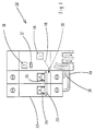
- a differential trip unit 10 is coupled and coupled to a unit two-pole circuit breaker 12 to form a modular differential circuit breaker 14.
- the mechanism 16 of the differential trip unit 10 is connected to the circuit breaker unit 12 by a mechanical trigger link 18 acting on the common trigger bar 20 of the circuit breaker block 12, for the transmission of a differential trip order.
- a bracket 22 connects the two levers 24, 26 for actuating the two poles of the circuit breaker block 12.
- a totalizing transformer 28 In addition to the mechanism 16 inside the differential trip unit 10 (see Figures 2 and 3), a totalizing transformer 28, a test and signaling circuit 29 to test button 30 and trigger indicator 32, an electromagnetic relay 34 trigger, and an electronic processing circuit 36 with auxiliary power source.
- the summing transformer 28 comprises a magnetic circuit in the form of a toroid crossed by power conductors 38, 40 electrically connected to the lower terminals of the circuit breaker block 12, and constituting the primary winding of transformer 28.
- a secondary winding 42 is wound on the toroid, and is electrically connected by wires 44 at the input of the electronic circuit 36.
- the output of the electronic circuit 36 is connected by an electrical connection 46 to the coil 48 of the trip relay 34.
- the kinematics of the mechanism 16 is similar to that described in detail in the document FR-A-2.437.692, but without the second reset link.
- the stirrup 22 of the levers 24, 26 is not mechanically coupled to the mechanism 16, being given that the trip relay 34 is a simple coil actuator 48 for transmitting current, without permanent magnet of polarization.
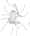
- the mechanical link 18 for triggering the mechanism 16 comprises a drawer 50 sliding fitted with a control lug 52 arranged opposite the actuating pin 54 trigger relay 34 with interposition of a clearance 55 of less than one millimeter.
- the trip relay includes a support means 56 made of insulating plastic material having a U-shaped structure, composed of a sheath 58 tubular arranged in the central part, and two lateral legs 60, 62 for positioning extending parallel to each other.
- the sheath 58 is framed longitudinally by two flanges 64, 66 located in the extension of the legs 60, 62 for housing the coil 48.
- Inside the bore 68 of the insulating sleeve 58 is slidably mounted axial a magnetic core 70 mechanically coupled to the actuating stud 54.
- a return spring 72 is interposed between a shoulder 73 of the core 70 and a surface 74 fixed support of the sheath 58 coaxially surrounding the stud 54, so as to bias the core 70 to the inactive position ( Figure 7) when the coil 48 is not excited by the electronic circuit 36.
- This inactive position is precisely defined at by means of a stop 76 secured to the stud 54 and bearing against a protuberance 78 of the sheath 58.
- the totalizing transformer 28 issues a trip order to the circuit electronic 36, which causes the excitation of the coil 48 of the relay 34.
- the core 70 mobile is moved in translation to the active position by compressing the spring 72, and the nipple 54 simultaneously drives the drawer 50 in the same direction for the actuation of the trigger link 18 to the triggered position. Unlocking the snap of the poles of the circuit breaker block 12 then causes the contacts to open.
- the support means 56 occupies a predetermined place in the trip unit 10 by engaging the ends of the positioning legs 60, 62 in a first pair of notches 80, 82 ( Figures 2 and 3) formed in the housing 84 insulating.
- a second pair of notches 86, 88 ( Figure 3) is provided in the housing 84 for receive centering tabs 90, 92 ( Figure 4) located at the sleeve 58.
- the setting in place of the support means 56 in the four support points defined by the notches 80, 82, 86, 88 ensures the precise positioning of the trip relay 34 relative to the mechanism 16, making it possible to automatically obtain the desired clearance 55 in the inactive position.
- At least one 90 (FIG. 4) of the centering tabs has a lug 96 intended to snap onto a rim of the notch 86 to secure the captive attachment of the means support 56 on the housing 84.
- the positioning leg 60 is equipped with a protuberance, in which is arranged a shoulder 98 intended to promote the maintenance support medium stable 56.
- a spring 100 is interposed between the inner wall of the housing 84 and the end of drawer 50 so as to urge drawer 50 in the tripping direction, against of the action of the reset spring (not shown). This polarization of the drawer 50 by the spring 100 makes it possible to obtain a function for memorizing the state of the trigger indicator 32.
Abstract
Description
L'invention est relative à un bloc déclencheur différentiel destiné à être accolé et accouplé à un bloc disjoncteur multipolaire pour constituer un disjoncteur différentiel modulaire, ledit bloc déclencheur étant logé dans un boítier isolant renfermant :
- un détecteur de courant différentiel comprenant un transformateur totalisateur en forme de tore traversé par des conducteurs de puissance constituant l'enroulement primaire,
- un mécanisme de commande piloté par un relais électromagnétique de déclenchement à téton d'actionnement pour transmettre en position active un ordre de déclenchement du relais au bloc disjoncteur par l'intermédiaire d'une liaison mécanique de déclenchement ,
- des moyens d'excitation de la bobine du relais lorsque la tension aux bornes de l'enroulement secondaire du transformateur totalisateur dépasse un seuil prédéterminé,
- et un circuit d'essai et de signalisation à bouton test et à indicateur de déclenchement.
- a differential current detector comprising a totalizing transformer in the form of a toroid crossed by power conductors constituting the primary winding,
- a control mechanism controlled by an electromagnetic tripping relay with an actuating pin for transmitting in the active position a tripping order from the relay to the circuit breaker block via a mechanical tripping link,
- means for energizing the relay coil when the voltage across the secondary winding of the summation transformer exceeds a predetermined threshold,
- and a test and signaling circuit with test button and trip indicator.
Un bloc déclencheur différentiel du genre mentionné est décrit dans le document FR-A-2.437.692 de la demanderesse. Le relais utilisé est du type polarisé grâce à l'usage d'un aimant permanent dont le flux magnétique dans l'entrefer se soustrait de celui engendré par une bobine électromagnétique. L'armature mobile est formée par une palette pivotante, et l'énergie nécessaire pour assurer le déclenchement est très réduite, et est produite par le courant de défaut. Un tel déclencheur ne nécessite pas de source d'alimentation auxiliaire, mais la fabrication du relais polarisé est relativement coûteuse et compliquée.A differential trip unit of the kind mentioned is described in document FR-A-2,437,692 of the plaintiff. The relay used is of the polarized type thanks to the use of a permanent magnet whose magnetic flux in the air gap is subtracted from that generated by an electromagnetic coil. The movable frame is formed by a pivoting pallet, and the energy required to trigger is very low, and is produced by the fault current. Such a release does not require an auxiliary power source, but the manufacture of the polarized relay is relatively expensive and complicated.
L'objet de l'invention consiste à réaliser un bloc déclencheur différentiel utilisant un relais de déclenchement de structure simplifiée.The object of the invention is to produce a differential trip unit using a relay of triggering of simplified structure.
Le bloc déclencheur différentiel selon l'invention est caractérisé en ce que les moyens d'excitation de la bobine sont agencés sur un circuit électronique de traitement ayant une source d'alimentation auxiliaire, une entrée connectée à l'enroulement secondaire du transformateur totalisateur , et une sortie en liaison électrique avec la bobine, et que le relais de déclenchement comporte des moyens de positionnement destinés à être engagés dans des encoches conjuguées du boítier pour obtenir en position inactive un jeu prédéterminé entre le téton d'actionnement et un ergot de commande de la liaison mécanique de déclenchement . The differential trip unit according to the invention is characterized in that the means excitation of the coil are arranged on an electronic processing circuit having a auxiliary power source, an input connected to the secondary winding of the totalizing transformer, and an output in electrical connection with the coil, and that the trip relay includes positioning means intended to be engaged in conjugate notches in the housing to obtain a game in the inactive position predetermined between the actuating pin and a connection control lug trigger mechanism.
Les moyens de positionnement du relais sont agencés sur un moyen de support en matériau plastique isolant comprenant un fourreau tubulaire sur lequel est enroulée la bobine entre deux flasques.The relay positioning means are arranged on a support means in insulating plastic material comprising a tubular sheath on which is wound the coil between two flanges.
Selon un mode de réalisation préférée de l'invention, le moyen de support comporte une structure monobloc en U ayant deux jambes latérales de positionnement s'étendant parallèlement l'une à l'autre, et perpendiculairement au fourreau , et deux pattes de centrage situées au niveau du fourreau .According to a preferred embodiment of the invention, the support means comprises a monobloc U-shaped structure having two lateral positioning legs extending parallel to each other, and perpendicular to the sheath, and two legs of centering located at the level of the sheath.
D'autres avantages et caractéristiques ressortiront plus clairement de la description qui va suivre d'un mode de réalisation de l'invention, donné à titre d'exemple non limitatif, et représenté aux dessins annexés, dans lesquels :
- la figure 1 est une vue schématique en élévation du disjoncteur différentiel modulaire selon l'invention;
- la figure 2 montre une vue en perspective du bloc déclencheur différentiel de la figure 1 après enlèvement du couvercle;
- la figure 3 représente une vue de face de la figure 2, après enlèvement du transformateur totalisateur, et de la carte électronique dans la partie basse du boítier.
- la figure 4 est une vue en perspective à échelle agrandie du support du relais de déclenchement;
- la figure 5 est une vue en perspective éclatée du relais de déclenchement;
- la figure 6 montre une vue du relais de la figure 5 après assemblage des pièces;
- la figure 7 est une vue en coupe selon la ligne 7-7 de la figure 3.
- Figure 1 is a schematic elevational view of the modular differential circuit breaker according to the invention;
- Figure 2 shows a perspective view of the differential release unit of Figure 1 after removal of the cover;
- Figure 3 shows a front view of Figure 2, after removal of the totalizing transformer, and the electronic card in the lower part of the housing.
- FIG. 4 is a perspective view on an enlarged scale of the support of the trip relay;
- Figure 5 is an exploded perspective view of the trip relay;
- Figure 6 shows a view of the relay of Figure 5 after assembly of the parts;
- FIG. 7 is a sectional view along line 7-7 of FIG. 3.
Sur la figure 1, un bloc déclencheur différentiel 10 est accolé et accouplé à un bloc
disjoncteur 12 bipolaire pour constituer un disjoncteur différentiel 14 modulaire. Le
mécanisme 16 du bloc déclencheur différentiel 10 est relié au bloc disjoncteur 12 par une
liaison mécanique de déclenchement 18 agissant sur la barre de déclenchement 20 commune
du bloc disjoncteur 12, pour la transmission d'un ordre de déclenchement différentiel. Un
étrier 22 relie les deux manettes 24, 26 d'actionnement des deux pôles du bloc disjoncteur
12. In FIG. 1, a
A l'intérieur du bloc déclencheur différentiel 10 se trouvent en plus du mécanisme 16 (voir
figures 2 et 3), un transformateur totalisateur 28, un circuit d'essai et de signalisation 29 à
bouton test 30 et à indicateur 32 de déclenchement, un relais 34 électromagnétique de
déclenchement, et un circuit électronique 36 de traitement à source d'alimentation auxiliaire.In addition to the
Le transformateur totalisateur 28 comporte un circuit magnétique en forme de tore traversé
par des conducteurs 38, 40 de puissance connectés électriquement aux bornes inférieures du
bloc disjoncteur 12, et constituant l'enroulement primaire du transformateur 28. Un
enroulement secondaire 42 est bobiné sur le tore, et est connecté électriquement par des fils
44 à l'entrée du circuit électronique 36. La sortie du circuit électronique 36 est branchée par
une liaison électrique 46 à la bobine 48 du relais de déclenchement 34.The summing
La cinématique du mécanisme 16 est similaire à celle décrite en détail dans le document
FR-A-2.437.692, mais sans la deuxième liaison de réarmement. On remarque en effet que
l'étrier 22 des manettes 24, 26 n'est pas accouplé mécaniquement au mécanisme 16, étant
donné que le relais de déclenchement 34 est un simple actionneur à bobine 48 d'émission de
courant, sans aimant permanent de polarisation.The kinematics of the
La liaison mécanique 18 de déclenchement du mécanisme 16 comporte un tiroir 50
coulissant équipé d'un ergot 52 de commande disposé en regard du téton 54 d'actionnement
du relais de déclenchement 34 avec interposition d'un jeu 55 inférieur à un millimètre.The
En référence aux figures 4 à 7, le relais de déclenchement comporte un moyen de support
56 en matériau plastique isolant ayant une structure en U, composée d'un fourreau 58
tubulaire agencé dans la partie centrale, et deux jambes latérales 60, 62 de positionnement
s'étendant parallèlement l'une à l'autre. Le fourreau 58 est encadré longitudinalement par
deux flasques 64, 66 situées dans le prolongement des jambes 60, 62 pour le logement de
la bobine 48. A l'intérieur de l'alésage 68 du fourreau 58 isolant est monté à coulissement
axial un noyau magnétique 70 accouplé mécaniquement au téton 54 d'actionnement. Un
ressort de rappel 72 est interposé entre un épaulement 73 du noyau 70 et une surface
d'appui 74 fixe du fourreau 58 en entourant coaxialement le téton 54, de manière à
solliciter le noyau 70 vers la position inactive (figure 7) lorsque la bobine 48 n'est pas
excitée par le circuit électronique 36. Cette position inactive est définie avec précision au
moyen d'une butée 76 solidaire du téton 54 et venant en appui contre une protubérance 78 du fourreau 58. With reference to FIGS. 4 to 7, the trip relay includes a support means
56 made of insulating plastic material having a U-shaped structure, composed of a
En cas d'apparition d'un défaut d'isolement sur le réseau protégé par le disjoncteur
différentiel 14, le transformateur totalisateur 28 émet un ordre de déclenchement au circuit
électronique 36, lequel provoque l'excitation de la bobine 48 du relais 34. Le noyau 70
mobile est déplacé en translation vers la position active en comprimant le ressort 72, et le
téton 54 entraíne simultanément le tiroir 50 dans le même sens pour l'actionnement de la
liaison de déclenchement 18 vers la position déclenchée. Le déverrouillage de l'accrochage
des pôles du bloc disjoncteur 12 provoque alors l'ouverture des contacts.In the event of an insulation fault appearing on the network protected by the
L'ajustage du jeu 55 axial entre le téton 54 et l'ergot 52 de commande du tiroir de
déclenchement 50 lorsque le relais 34 se trouve en position inactive, nécessite un
positionnement correct du relais 34 par rapport au mécanisme 16 du bloc déclencheur
différentiel 10. A cet effet, le moyen support 56 occupe une place prédéterminée dans le
bloc déclencheur 10 grâce à l'engagement des extrémités des jambes de positionnement 60,
62 dans une première paire d'encoches 80, 82 (figures 2 et 3) ménagée dans le boítier 84
isolant. Une deuxième paire d'encoches 86, 88 (figure 3) est prévue dans le boítier 84 pour
recevoir des pattes de centrage 90, 92 (figure 4) situées au niveau du fourreau 58. La mise
en place du moyen support 56 dans les quatre points d'appui définis par les encoches 80,
82, 86, 88 assure le positionnement précis du relais 34 de déclenchement par rapport au
mécanisme 16, permettant d'obtenir automatiquement le jeu 55 souhaité en position inactive.The adjustment of the
Au moins une 90 (figure 4) des pattes de centrage est dotée d'un ergot 96 destiné à
s'encliqueter sur un rebord de l'encoche 86 pour assurer la fixation imperdable du moyen
support 56 sur le boítier 84. La jambe de positionnement 60 est équipée d'une
protubérance, dans laquelle est agencé un épaulement 98 destiné à favoriser le maintien
stable du moyen support 56.At least one 90 (FIG. 4) of the centering tabs has a lug 96 intended to
snap onto a rim of the
Sur la figure 7, un ressort 100 est intercalé entre la paroi interne du boítier 84 et l'extrémité
du tiroir 50 de manière à solliciter le tiroir 50 dans le sens du déclenchement, à l'encontre
de l'action du ressort de réarmement (non représenté). Cette polarisation du tiroir 50 par le
ressort 100 permet d'obtenir une fonction de mémorisation de l'état de l'indicateur 32 de déclenchement.In Figure 7, a
Il est clair que l'effet de centrage tridimensionnel du relais 34 de déclenchement par rapport
au mécanisme 16 du bloc déclencheur différentiel 10 pourrait être obtenu par un moyen
support 56 de forme différente à celle décrite précédemment.It is clear that the three-dimensional centering effect of the
Claims (7)
- A differential trip unit (10) designed to be adjoined and coupled to a multipole circuit breaker unit (12) to form a modular differential circuit breaker (14), said trip unit (10) being housed in an insulating case (84) containing :characterized in that the means for excitation of the coil (48) are arranged on an electronic processing circuit (36) having an auxiliary power source, an input connected to the secondary winding (42) of the summing transformer (28), and an output in electrical connection with the coil (48), and that the trip relay (16) comprises positioning means (60, 62; 90, 92) designed to be engaged in conjugate notches (80, 82; 86, 88) of the case (84) to obtain in the inactive position a preset clearance (55) between the actuating pin (54) and an operating spigot (52) of the mechanical tripping link (18).a differential current detector comprising a summing transformer (28) in the form of a toroid through which power conductors (38, 40) forming the primary winding pass,an operating mechanism (16) controlled by an electromagnetic trip relay (34) with an actuating pin (54) to transmit in the active position a tripping order of the relay (34) to the circuit breaker unit (12) via a mechanical tripping link (18),means for excitation of the coil (48) of the relay (34) when the voltage at the terminals of the secondary winding (42) of the summing transformer (28) exceeds a preset threshold,and a test and signalling circuit (29) with test button (30) and tripping indicator (32),
- The differential trip unit according to claim 1, characterized in that the positioning means of the relay (34) are arranged on a support means (56) made of insulating plastic material comprising a tubular sheath (58) on which the coil (48) is wound between two flanges (64, 66).
- The differential trip unit according to claim 2, characterized in that the sheath (58) is equipped with a bore (68) inside which a magnetic core (70) mechanically coupled to the actuating pin (54) is mounted with axial sliding, and that a return spring (72) is fitted in the bore (68) interposed between a shoulder (73) of the core (70) and a bearing surface (74) of the sheath (58).
- The differential trip unit according to claim 2 or 3, characterized in that the support means (56) comprises a U-shaped monobloc structure having two lateral positioning legs (60, 62) extending parallel to one another, and perpendicularly to the sheath (58), and two centering lugs (90, 92) situated at the level of the sheath (58).
- The differential trip unit according to claim 4, characterized in that at least one (90) of the centering lugs is provided with a clipping spigot (96).
- The differential trip unit according to claim 2 or 3, characterized in that the actuating pin (54) of the relay (34) comprises a stop (76) coming up against a protuberance (78) of the sheath (58) in the inactive position of the magnetic core (70).
- The differential trip unit according to claim 1, characterized in that the operating spigot (52) of the mechanical tripping link is arranged on a movable rack (50) urged by a spring (100) in the tripping direction.
Applications Claiming Priority (2)
| Application Number | Priority Date | Filing Date | Title |
|---|---|---|---|
| FR9400927A FR2715517B1 (en) | 1994-01-26 | 1994-01-26 | Differential trip unit. |
| FR9400927 | 1994-01-26 |
Publications (2)
| Publication Number | Publication Date |
|---|---|
| EP0665569A1 EP0665569A1 (en) | 1995-08-02 |
| EP0665569B1 true EP0665569B1 (en) | 2000-03-22 |
Family
ID=9459493
Family Applications (1)
| Application Number | Title | Priority Date | Filing Date |
|---|---|---|---|
| EP95410002A Expired - Lifetime EP0665569B1 (en) | 1994-01-26 | 1995-01-11 | Diffential trip unit |
Country Status (8)
| Country | Link |
|---|---|
| EP (1) | EP0665569B1 (en) |
| KR (1) | KR950034346A (en) |
| CN (1) | CN1048115C (en) |
| AT (1) | ATE191099T1 (en) |
| BR (1) | BR9500317A (en) |
| DE (1) | DE69515711T2 (en) |
| ES (1) | ES2144592T3 (en) |
| FR (1) | FR2715517B1 (en) |
Cited By (67)
| Publication number | Priority date | Publication date | Assignee | Title |
|---|---|---|---|---|
| US6087913A (en) | 1998-11-20 | 2000-07-11 | General Electric Company | Circuit breaker mechanism for a rotary contact system |
| US6114641A (en) | 1998-05-29 | 2000-09-05 | General Electric Company | Rotary contact assembly for high ampere-rated circuit breakers |
| US6166344A (en) | 1999-03-23 | 2000-12-26 | General Electric Company | Circuit breaker handle block |
| US6172584B1 (en) | 1999-12-20 | 2001-01-09 | General Electric Company | Circuit breaker accessory reset system |
| US6175288B1 (en) | 1999-08-27 | 2001-01-16 | General Electric Company | Supplemental trip unit for rotary circuit interrupters |
| US6184761B1 (en) | 1999-12-20 | 2001-02-06 | General Electric Company | Circuit breaker rotary contact arrangement |
| US6188036B1 (en) | 1999-08-03 | 2001-02-13 | General Electric Company | Bottom vented circuit breaker capable of top down assembly onto equipment |
| US6204743B1 (en) | 2000-02-29 | 2001-03-20 | General Electric Company | Dual connector strap for a rotary contact circuit breaker |
| US6211758B1 (en) | 2000-01-11 | 2001-04-03 | General Electric Company | Circuit breaker accessory gap control mechanism |
| US6211757B1 (en) | 2000-03-06 | 2001-04-03 | General Electric Company | Fast acting high force trip actuator |
| US6215379B1 (en) | 1999-12-23 | 2001-04-10 | General Electric Company | Shunt for indirectly heated bimetallic strip |
| US6218919B1 (en) | 2000-03-15 | 2001-04-17 | General Electric Company | Circuit breaker latch mechanism with decreased trip time |
| US6218917B1 (en) | 1999-07-02 | 2001-04-17 | General Electric Company | Method and arrangement for calibration of circuit breaker thermal trip unit |
| US6225881B1 (en) | 1998-04-29 | 2001-05-01 | General Electric Company | Thermal magnetic circuit breaker |
| US6229413B1 (en) | 1999-10-19 | 2001-05-08 | General Electric Company | Support of stationary conductors for a circuit breaker |
| US6232859B1 (en) | 2000-03-15 | 2001-05-15 | General Electric Company | Auxiliary switch mounting configuration for use in a molded case circuit breaker |
| US6232856B1 (en) | 1999-11-02 | 2001-05-15 | General Electric Company | Magnetic shunt assembly |
| US6232570B1 (en) | 1999-09-16 | 2001-05-15 | General Electric Company | Arcing contact arrangement |
| US6239677B1 (en) | 2000-02-10 | 2001-05-29 | General Electric Company | Circuit breaker thermal magnetic trip unit |
| US6239398B1 (en) | 2000-02-24 | 2001-05-29 | General Electric Company | Cassette assembly with rejection features |
| US6252365B1 (en) | 1999-08-17 | 2001-06-26 | General Electric Company | Breaker/starter with auto-configurable trip unit |
| US6262642B1 (en) | 1999-11-03 | 2001-07-17 | General Electric Company | Circuit breaker rotary contact arm arrangement |
| US6262872B1 (en) | 1999-06-03 | 2001-07-17 | General Electric Company | Electronic trip unit with user-adjustable sensitivity to current spikes |
| US6268991B1 (en) | 1999-06-25 | 2001-07-31 | General Electric Company | Method and arrangement for customizing electronic circuit interrupters |
| US6281461B1 (en) | 1999-12-27 | 2001-08-28 | General Electric Company | Circuit breaker rotor assembly having arc prevention structure |
| US6281458B1 (en) | 2000-02-24 | 2001-08-28 | General Electric Company | Circuit breaker auxiliary magnetic trip unit with pressure sensitive release |
| US6300586B1 (en) | 1999-12-09 | 2001-10-09 | General Electric Company | Arc runner retaining feature |
| US6310307B1 (en) | 1999-12-17 | 2001-10-30 | General Electric Company | Circuit breaker rotary contact arm arrangement |
| US6317018B1 (en) | 1999-10-26 | 2001-11-13 | General Electric Company | Circuit breaker mechanism |
| US6326869B1 (en) | 1999-09-23 | 2001-12-04 | General Electric Company | Clapper armature system for a circuit breaker |
| US6326868B1 (en) | 1997-07-02 | 2001-12-04 | General Electric Company | Rotary contact assembly for high ampere-rated circuit breaker |
| US6340925B1 (en) | 2000-03-01 | 2002-01-22 | General Electric Company | Circuit breaker mechanism tripping cam |
| US6346869B1 (en) | 1999-12-28 | 2002-02-12 | General Electric Company | Rating plug for circuit breakers |
| US6346868B1 (en) | 2000-03-01 | 2002-02-12 | General Electric Company | Circuit interrupter operating mechanism |
| US6362711B1 (en) | 2000-11-10 | 2002-03-26 | General Electric Company | Circuit breaker cover with screw locating feature |
| US6366188B1 (en) | 2000-03-15 | 2002-04-02 | General Electric Company | Accessory and recess identification system for circuit breakers |
| US6373357B1 (en) | 2000-05-16 | 2002-04-16 | General Electric Company | Pressure sensitive trip mechanism for a rotary breaker |
| US6373010B1 (en) | 2000-03-17 | 2002-04-16 | General Electric Company | Adjustable energy storage mechanism for a circuit breaker motor operator |
| US6377144B1 (en) | 1999-11-03 | 2002-04-23 | General Electric Company | Molded case circuit breaker base and mid-cover assembly |
| US6379196B1 (en) | 2000-03-01 | 2002-04-30 | General Electric Company | Terminal connector for a circuit breaker |
| US6380829B1 (en) | 2000-11-21 | 2002-04-30 | General Electric Company | Motor operator interlock and method for circuit breakers |
| US6388213B1 (en) | 2000-03-17 | 2002-05-14 | General Electric Company | Locking device for molded case circuit breakers |
| US6396369B1 (en) | 1999-08-27 | 2002-05-28 | General Electric Company | Rotary contact assembly for high ampere-rated circuit breakers |
| US6404314B1 (en) | 2000-02-29 | 2002-06-11 | General Electric Company | Adjustable trip solenoid |
| US6429760B1 (en) | 2000-10-19 | 2002-08-06 | General Electric Company | Cross bar for a conductor in a rotary breaker |
| US6429659B1 (en) | 2000-03-09 | 2002-08-06 | General Electric Company | Connection tester for an electronic trip unit |
| US6429759B1 (en) | 2000-02-14 | 2002-08-06 | General Electric Company | Split and angled contacts |
| US6448522B1 (en) | 2001-01-30 | 2002-09-10 | General Electric Company | Compact high speed motor operator for a circuit breaker |
| US6448521B1 (en) | 2000-03-01 | 2002-09-10 | General Electric Company | Blocking apparatus for circuit breaker contact structure |
| US6459349B1 (en) | 2000-03-06 | 2002-10-01 | General Electric Company | Circuit breaker comprising a current transformer with a partial air gap |
| US6459059B1 (en) | 2000-03-16 | 2002-10-01 | General Electric Company | Return spring for a circuit interrupter operating mechanism |
| US6469882B1 (en) | 2001-10-31 | 2002-10-22 | General Electric Company | Current transformer initial condition correction |
| US6472620B2 (en) | 2000-03-17 | 2002-10-29 | Ge Power Controls France Sas | Locking arrangement for circuit breaker draw-out mechanism |
| US6476698B1 (en) | 2000-03-17 | 2002-11-05 | General Electric Company | Convertible locking arrangement on breakers |
| US6476337B2 (en) | 2001-02-26 | 2002-11-05 | General Electric Company | Auxiliary switch actuation arrangement |
| US6476335B2 (en) | 2000-03-17 | 2002-11-05 | General Electric Company | Draw-out mechanism for molded case circuit breakers |
| US6479774B1 (en) | 2000-03-17 | 2002-11-12 | General Electric Company | High energy closing mechanism for circuit breakers |
| US6496347B1 (en) | 2000-03-08 | 2002-12-17 | General Electric Company | System and method for optimization of a circuit breaker mechanism |
| US6531941B1 (en) | 2000-10-19 | 2003-03-11 | General Electric Company | Clip for a conductor in a rotary breaker |
| US6559743B2 (en) | 2000-03-17 | 2003-05-06 | General Electric Company | Stored energy system for breaker operating mechanism |
| US6586693B2 (en) | 2000-03-17 | 2003-07-01 | General Electric Company | Self compensating latch arrangement |
| US6639168B1 (en) | 2000-03-17 | 2003-10-28 | General Electric Company | Energy absorbing contact arm stop |
| US6678135B2 (en) | 2001-09-12 | 2004-01-13 | General Electric Company | Module plug for an electronic trip unit |
| US6710988B1 (en) | 1999-08-17 | 2004-03-23 | General Electric Company | Small-sized industrial rated electric motor starter switch unit |
| US6747535B2 (en) | 2000-03-27 | 2004-06-08 | General Electric Company | Precision location system between actuator accessory and mechanism |
| US6804101B2 (en) | 2001-11-06 | 2004-10-12 | General Electric Company | Digital rating plug for electronic trip unit in circuit breakers |
| US6806800B1 (en) | 2000-10-19 | 2004-10-19 | General Electric Company | Assembly for mounting a motor operator on a circuit breaker |
Families Citing this family (6)
| Publication number | Priority date | Publication date | Assignee | Title |
|---|---|---|---|---|
| FR2752479B1 (en) * | 1996-08-13 | 1998-09-25 | Schneider Electric Sa | ELECTRONIC DIFFERENTIAL CIRCUIT BREAKER |
| US6037555A (en) | 1999-01-05 | 2000-03-14 | General Electric Company | Rotary contact circuit breaker venting arrangement including current transformer |
| US6239395B1 (en) * | 1999-10-14 | 2001-05-29 | General Electric Company | Auxiliary position switch assembly for a circuit breaker |
| FR2969369A1 (en) * | 2010-12-20 | 2012-06-22 | Schneider Electric Ind Sas | ELECTRICAL PROTECTION APPARATUS COMPRISING THE DIFFERENTIAL PROTECTION FUNCTION |
| KR101834813B1 (en) | 2014-03-17 | 2018-03-06 | 엘에스산전 주식회사 | Molded case circuit breaker |
| FR3069718B1 (en) * | 2017-07-25 | 2019-08-09 | Schneider Electric Industries Sas | DIFFERENTIAL ELECTRICAL PROTECTION APPARATUS |
Family Cites Families (5)
| Publication number | Priority date | Publication date | Assignee | Title |
|---|---|---|---|---|
| DE2834327C2 (en) * | 1978-08-04 | 1983-01-13 | Heinrich Kopp Gmbh & Co Kg, 8756 Kahl | Full electrical circuit breaker |
| DE3374487D1 (en) * | 1982-08-19 | 1987-12-17 | Bbc Brown Boveri & Cie | Circuit breaker with leakage current release |
| US5095398A (en) * | 1990-02-12 | 1992-03-10 | Square D Company | Electrical circuit breaker protection device |
| US5260676A (en) * | 1991-03-27 | 1993-11-09 | Westinghouse Electric Corp. | Dual wound trip solenoid |
| IE920641A1 (en) * | 1991-03-27 | 1992-10-07 | Westinghouse Electric Corp | Dual wound trip solenoid |
-
1994
- 1994-01-26 FR FR9400927A patent/FR2715517B1/en not_active Expired - Fee Related
-
1995
- 1995-01-11 ES ES95410002T patent/ES2144592T3/en not_active Expired - Lifetime
- 1995-01-11 AT AT95410002T patent/ATE191099T1/en not_active IP Right Cessation
- 1995-01-11 EP EP95410002A patent/EP0665569B1/en not_active Expired - Lifetime
- 1995-01-11 DE DE69515711T patent/DE69515711T2/en not_active Expired - Fee Related
- 1995-01-25 BR BR9500317A patent/BR9500317A/en not_active IP Right Cessation
- 1995-01-25 CN CN95101496A patent/CN1048115C/en not_active Expired - Fee Related
- 1995-01-25 KR KR1019950001324A patent/KR950034346A/en active IP Right Grant
Cited By (75)
| Publication number | Priority date | Publication date | Assignee | Title |
|---|---|---|---|---|
| US6326868B1 (en) | 1997-07-02 | 2001-12-04 | General Electric Company | Rotary contact assembly for high ampere-rated circuit breaker |
| US6225881B1 (en) | 1998-04-29 | 2001-05-01 | General Electric Company | Thermal magnetic circuit breaker |
| US6114641A (en) | 1998-05-29 | 2000-09-05 | General Electric Company | Rotary contact assembly for high ampere-rated circuit breakers |
| US6259048B1 (en) | 1998-05-29 | 2001-07-10 | General Electric Company | Rotary contact assembly for high ampere-rated circuit breakers |
| US6087913A (en) | 1998-11-20 | 2000-07-11 | General Electric Company | Circuit breaker mechanism for a rotary contact system |
| US6166344A (en) | 1999-03-23 | 2000-12-26 | General Electric Company | Circuit breaker handle block |
| US6262872B1 (en) | 1999-06-03 | 2001-07-17 | General Electric Company | Electronic trip unit with user-adjustable sensitivity to current spikes |
| US6400543B2 (en) | 1999-06-03 | 2002-06-04 | General Electric Company | Electronic trip unit with user-adjustable sensitivity to current spikes |
| US6268991B1 (en) | 1999-06-25 | 2001-07-31 | General Electric Company | Method and arrangement for customizing electronic circuit interrupters |
| US6218917B1 (en) | 1999-07-02 | 2001-04-17 | General Electric Company | Method and arrangement for calibration of circuit breaker thermal trip unit |
| US6188036B1 (en) | 1999-08-03 | 2001-02-13 | General Electric Company | Bottom vented circuit breaker capable of top down assembly onto equipment |
| US6252365B1 (en) | 1999-08-17 | 2001-06-26 | General Electric Company | Breaker/starter with auto-configurable trip unit |
| US6710988B1 (en) | 1999-08-17 | 2004-03-23 | General Electric Company | Small-sized industrial rated electric motor starter switch unit |
| US6175288B1 (en) | 1999-08-27 | 2001-01-16 | General Electric Company | Supplemental trip unit for rotary circuit interrupters |
| US6396369B1 (en) | 1999-08-27 | 2002-05-28 | General Electric Company | Rotary contact assembly for high ampere-rated circuit breakers |
| US6232570B1 (en) | 1999-09-16 | 2001-05-15 | General Electric Company | Arcing contact arrangement |
| US6326869B1 (en) | 1999-09-23 | 2001-12-04 | General Electric Company | Clapper armature system for a circuit breaker |
| US6229413B1 (en) | 1999-10-19 | 2001-05-08 | General Electric Company | Support of stationary conductors for a circuit breaker |
| US6317018B1 (en) | 1999-10-26 | 2001-11-13 | General Electric Company | Circuit breaker mechanism |
| US6232856B1 (en) | 1999-11-02 | 2001-05-15 | General Electric Company | Magnetic shunt assembly |
| US6262642B1 (en) | 1999-11-03 | 2001-07-17 | General Electric Company | Circuit breaker rotary contact arm arrangement |
| US6377144B1 (en) | 1999-11-03 | 2002-04-23 | General Electric Company | Molded case circuit breaker base and mid-cover assembly |
| US6300586B1 (en) | 1999-12-09 | 2001-10-09 | General Electric Company | Arc runner retaining feature |
| US6310307B1 (en) | 1999-12-17 | 2001-10-30 | General Electric Company | Circuit breaker rotary contact arm arrangement |
| US6172584B1 (en) | 1999-12-20 | 2001-01-09 | General Electric Company | Circuit breaker accessory reset system |
| US6184761B1 (en) | 1999-12-20 | 2001-02-06 | General Electric Company | Circuit breaker rotary contact arrangement |
| US6215379B1 (en) | 1999-12-23 | 2001-04-10 | General Electric Company | Shunt for indirectly heated bimetallic strip |
| US6281461B1 (en) | 1999-12-27 | 2001-08-28 | General Electric Company | Circuit breaker rotor assembly having arc prevention structure |
| US6346869B1 (en) | 1999-12-28 | 2002-02-12 | General Electric Company | Rating plug for circuit breakers |
| US6211758B1 (en) | 2000-01-11 | 2001-04-03 | General Electric Company | Circuit breaker accessory gap control mechanism |
| US6239677B1 (en) | 2000-02-10 | 2001-05-29 | General Electric Company | Circuit breaker thermal magnetic trip unit |
| US6429759B1 (en) | 2000-02-14 | 2002-08-06 | General Electric Company | Split and angled contacts |
| US6281458B1 (en) | 2000-02-24 | 2001-08-28 | General Electric Company | Circuit breaker auxiliary magnetic trip unit with pressure sensitive release |
| US6239398B1 (en) | 2000-02-24 | 2001-05-29 | General Electric Company | Cassette assembly with rejection features |
| US6313425B1 (en) | 2000-02-24 | 2001-11-06 | General Electric Company | Cassette assembly with rejection features |
| US6204743B1 (en) | 2000-02-29 | 2001-03-20 | General Electric Company | Dual connector strap for a rotary contact circuit breaker |
| US6404314B1 (en) | 2000-02-29 | 2002-06-11 | General Electric Company | Adjustable trip solenoid |
| US6724286B2 (en) | 2000-02-29 | 2004-04-20 | General Electric Company | Adjustable trip solenoid |
| US6448521B1 (en) | 2000-03-01 | 2002-09-10 | General Electric Company | Blocking apparatus for circuit breaker contact structure |
| US6466117B2 (en) | 2000-03-01 | 2002-10-15 | General Electric Company | Circuit interrupter operating mechanism |
| US6346868B1 (en) | 2000-03-01 | 2002-02-12 | General Electric Company | Circuit interrupter operating mechanism |
| US6379196B1 (en) | 2000-03-01 | 2002-04-30 | General Electric Company | Terminal connector for a circuit breaker |
| US6340925B1 (en) | 2000-03-01 | 2002-01-22 | General Electric Company | Circuit breaker mechanism tripping cam |
| US6388547B1 (en) | 2000-03-01 | 2002-05-14 | General Electric Company | Circuit interrupter operating mechanism |
| US6590482B2 (en) | 2000-03-01 | 2003-07-08 | General Electric Company | Circuit breaker mechanism tripping cam |
| US6459349B1 (en) | 2000-03-06 | 2002-10-01 | General Electric Company | Circuit breaker comprising a current transformer with a partial air gap |
| US6211757B1 (en) | 2000-03-06 | 2001-04-03 | General Electric Company | Fast acting high force trip actuator |
| US6496347B1 (en) | 2000-03-08 | 2002-12-17 | General Electric Company | System and method for optimization of a circuit breaker mechanism |
| US6534991B2 (en) | 2000-03-09 | 2003-03-18 | General Electric Company | Connection tester for an electronic trip unit |
| US6429659B1 (en) | 2000-03-09 | 2002-08-06 | General Electric Company | Connection tester for an electronic trip unit |
| US6232859B1 (en) | 2000-03-15 | 2001-05-15 | General Electric Company | Auxiliary switch mounting configuration for use in a molded case circuit breaker |
| US6218919B1 (en) | 2000-03-15 | 2001-04-17 | General Electric Company | Circuit breaker latch mechanism with decreased trip time |
| US6366188B1 (en) | 2000-03-15 | 2002-04-02 | General Electric Company | Accessory and recess identification system for circuit breakers |
| US6459059B1 (en) | 2000-03-16 | 2002-10-01 | General Electric Company | Return spring for a circuit interrupter operating mechanism |
| US6472620B2 (en) | 2000-03-17 | 2002-10-29 | Ge Power Controls France Sas | Locking arrangement for circuit breaker draw-out mechanism |
| US6559743B2 (en) | 2000-03-17 | 2003-05-06 | General Electric Company | Stored energy system for breaker operating mechanism |
| US6476698B1 (en) | 2000-03-17 | 2002-11-05 | General Electric Company | Convertible locking arrangement on breakers |
| US6639168B1 (en) | 2000-03-17 | 2003-10-28 | General Electric Company | Energy absorbing contact arm stop |
| US6476335B2 (en) | 2000-03-17 | 2002-11-05 | General Electric Company | Draw-out mechanism for molded case circuit breakers |
| US6479774B1 (en) | 2000-03-17 | 2002-11-12 | General Electric Company | High energy closing mechanism for circuit breakers |
| US6373010B1 (en) | 2000-03-17 | 2002-04-16 | General Electric Company | Adjustable energy storage mechanism for a circuit breaker motor operator |
| US6388213B1 (en) | 2000-03-17 | 2002-05-14 | General Electric Company | Locking device for molded case circuit breakers |
| US6586693B2 (en) | 2000-03-17 | 2003-07-01 | General Electric Company | Self compensating latch arrangement |
| US6747535B2 (en) | 2000-03-27 | 2004-06-08 | General Electric Company | Precision location system between actuator accessory and mechanism |
| US6373357B1 (en) | 2000-05-16 | 2002-04-16 | General Electric Company | Pressure sensitive trip mechanism for a rotary breaker |
| US6531941B1 (en) | 2000-10-19 | 2003-03-11 | General Electric Company | Clip for a conductor in a rotary breaker |
| US6429760B1 (en) | 2000-10-19 | 2002-08-06 | General Electric Company | Cross bar for a conductor in a rotary breaker |
| US6806800B1 (en) | 2000-10-19 | 2004-10-19 | General Electric Company | Assembly for mounting a motor operator on a circuit breaker |
| US6362711B1 (en) | 2000-11-10 | 2002-03-26 | General Electric Company | Circuit breaker cover with screw locating feature |
| US6380829B1 (en) | 2000-11-21 | 2002-04-30 | General Electric Company | Motor operator interlock and method for circuit breakers |
| US6448522B1 (en) | 2001-01-30 | 2002-09-10 | General Electric Company | Compact high speed motor operator for a circuit breaker |
| US6476337B2 (en) | 2001-02-26 | 2002-11-05 | General Electric Company | Auxiliary switch actuation arrangement |
| US6678135B2 (en) | 2001-09-12 | 2004-01-13 | General Electric Company | Module plug for an electronic trip unit |
| US6469882B1 (en) | 2001-10-31 | 2002-10-22 | General Electric Company | Current transformer initial condition correction |
| US6804101B2 (en) | 2001-11-06 | 2004-10-12 | General Electric Company | Digital rating plug for electronic trip unit in circuit breakers |
Also Published As
| Publication number | Publication date |
|---|---|
| CN1111805A (en) | 1995-11-15 |
| ATE191099T1 (en) | 2000-04-15 |
| FR2715517B1 (en) | 1996-03-22 |
| DE69515711T2 (en) | 2000-08-31 |
| CN1048115C (en) | 2000-01-05 |
| KR950034346A (en) | 1995-12-28 |
| ES2144592T3 (en) | 2000-06-16 |
| FR2715517A1 (en) | 1995-07-28 |
| DE69515711D1 (en) | 2000-04-27 |
| BR9500317A (en) | 1995-10-17 |
| EP0665569A1 (en) | 1995-08-02 |
Similar Documents
| Publication | Publication Date | Title |
|---|---|---|
| EP0665569B1 (en) | Diffential trip unit | |
| EP0264314B1 (en) | Multipole differential circuit breaker with a modular assembly | |
| EP0017575B2 (en) | Contactor with rapid opening in the event of a fault | |
| EP0264313B1 (en) | Electric differential-protection apparatus with a test circuit | |
| EP1126490B1 (en) | Circuit breaker with latch and toggle mechanism operating in perpendicular planes | |
| EP0331586B1 (en) | Actuating mechanism of an auxiliary tripping block for a modular circuit breaker | |
| AU668972B2 (en) | Circuit breaker with auxiliary switch actuated by cascaded actuating members | |
| FR2639760A1 (en) | MODULAR CIRCUIT BREAKER EQUIPPED WITH AN AUXILIARY TRIP UNIT WITH INDEPENDENT OR AUTOMATIC RESET | |
| EP0619591A1 (en) | Magnetothermal trip unit | |
| FR2779568A1 (en) | ELECTRICAL CUT-OFF DEVICE INCLUDING A DIFFERENTIAL TRIP DEVICE AND CIRCUIT BREAKER INCLUDING SUCH A DEVICE | |
| US6307453B1 (en) | Circuit breaker with instantaneous trip provided by main conductor routed through magnetic circuit of electronic trip motor | |
| EP0068934B2 (en) | Multipole moulded-case circuit breaker with a static tripping unit | |
| US4090156A (en) | Circuit breaker having solid state and thermal-magnetic trip means | |
| FR2752479A1 (en) | Differential electronic circuit breaker for electrical Protection | |
| EP0275750A1 (en) | Bipolar differential interrupter with fault indicator | |
| EP1117115B1 (en) | Differential electric protection device, in particular a differential switch | |
| EP0099786B1 (en) | Two-phase differential circuit breaker | |
| EP0665623A1 (en) | Test device for differential circuit breaker and differential circuit breaker containing the same | |
| EP2743958B1 (en) | Electric current breaking apparatus, in particular a coupling breaker | |
| JP4232569B2 (en) | Earth leakage display device for earth leakage breaker | |
| FR2627324A1 (en) | Differential circuit breaker with neutral by=pass - includes cut=out relay connected to transformer torus carrying phase conductors | |
| EP0456586B1 (en) | Test circuit for a differential tripping device | |
| FR2475291A1 (en) | LV multipolar differential protection switch - has spring-mounted contact arms with limited relative rotation and translation | |
| EP0079270A1 (en) | Low-voltage branch circuit breaker provided with a remotely controlled calibration switch | |
| FR3102292A1 (en) | Protection device for an electrical installation in alternating current |
Legal Events
| Date | Code | Title | Description |
|---|---|---|---|
| PUAI | Public reference made under article 153(3) epc to a published international application that has entered the european phase |
Free format text: ORIGINAL CODE: 0009012 |
|
| AK | Designated contracting states |
Kind code of ref document: A1 Designated state(s): AT DE ES GB IT |
|
| 17P | Request for examination filed |
Effective date: 19960127 |
|
| GRAG | Despatch of communication of intention to grant |
Free format text: ORIGINAL CODE: EPIDOS AGRA |
|
| 17Q | First examination report despatched |
Effective date: 19990406 |
|
| GRAG | Despatch of communication of intention to grant |
Free format text: ORIGINAL CODE: EPIDOS AGRA |
|
| GRAH | Despatch of communication of intention to grant a patent |
Free format text: ORIGINAL CODE: EPIDOS IGRA |
|
| RAP1 | Party data changed (applicant data changed or rights of an application transferred) |
Owner name: SCHNEIDER ELECTRIC INDUSTRIES SA |
|
| GRAH | Despatch of communication of intention to grant a patent |
Free format text: ORIGINAL CODE: EPIDOS IGRA |
|
| GRAA | (expected) grant |
Free format text: ORIGINAL CODE: 0009210 |
|
| RAP1 | Party data changed (applicant data changed or rights of an application transferred) |
Owner name: SCHNEIDER ELECTRIC INDUSTRIES SA |
|
| AK | Designated contracting states |
Kind code of ref document: B1 Designated state(s): AT DE ES GB IT |
|
| REF | Corresponds to: |
Ref document number: 191099 Country of ref document: AT Date of ref document: 20000415 Kind code of ref document: T |
|
| REF | Corresponds to: |
Ref document number: 69515711 Country of ref document: DE Date of ref document: 20000427 |
|
| GBT | Gb: translation of ep patent filed (gb section 77(6)(a)/1977) |
Effective date: 20000503 |
|
| ITF | It: translation for a ep patent filed |
Owner name: EUROPATENT S.A.S. |
|
| REG | Reference to a national code |
Ref country code: ES Ref legal event code: FG2A Ref document number: 2144592 Country of ref document: ES Kind code of ref document: T3 |
|
| PGFP | Annual fee paid to national office [announced via postgrant information from national office to epo] |
Ref country code: DE Payment date: 20001214 Year of fee payment: 7 |
|
| PGFP | Annual fee paid to national office [announced via postgrant information from national office to epo] |
Ref country code: GB Payment date: 20010110 Year of fee payment: 7 |
|
| PGFP | Annual fee paid to national office [announced via postgrant information from national office to epo] |
Ref country code: AT Payment date: 20010116 Year of fee payment: 7 |
|
| PLBE | No opposition filed within time limit |
Free format text: ORIGINAL CODE: 0009261 |
|
| STAA | Information on the status of an ep patent application or granted ep patent |
Free format text: STATUS: NO OPPOSITION FILED WITHIN TIME LIMIT |
|
| PGFP | Annual fee paid to national office [announced via postgrant information from national office to epo] |
Ref country code: ES Payment date: 20010122 Year of fee payment: 7 |
|
| 26N | No opposition filed | ||
| REG | Reference to a national code |
Ref country code: GB Ref legal event code: IF02 |
|
| PG25 | Lapsed in a contracting state [announced via postgrant information from national office to epo] |
Ref country code: GB Free format text: LAPSE BECAUSE OF NON-PAYMENT OF DUE FEES Effective date: 20020111 Ref country code: AT Free format text: LAPSE BECAUSE OF NON-PAYMENT OF DUE FEES Effective date: 20020111 |
|
| PG25 | Lapsed in a contracting state [announced via postgrant information from national office to epo] |
Ref country code: ES Free format text: LAPSE BECAUSE OF NON-PAYMENT OF DUE FEES Effective date: 20020112 |
|
| PG25 | Lapsed in a contracting state [announced via postgrant information from national office to epo] |
Ref country code: DE Free format text: LAPSE BECAUSE OF NON-PAYMENT OF DUE FEES Effective date: 20020801 |
|
| GBPC | Gb: european patent ceased through non-payment of renewal fee |
Effective date: 20020111 |
|
| REG | Reference to a national code |
Ref country code: ES Ref legal event code: FD2A Effective date: 20031022 |
|
| PG25 | Lapsed in a contracting state [announced via postgrant information from national office to epo] |
Ref country code: IT Free format text: LAPSE BECAUSE OF NON-PAYMENT OF DUE FEES Effective date: 20050111 |