EP0665161B1 - Parachute materials - Google Patents
Parachute materials Download PDFInfo
- Publication number
- EP0665161B1 EP0665161B1 EP95104279A EP95104279A EP0665161B1 EP 0665161 B1 EP0665161 B1 EP 0665161B1 EP 95104279 A EP95104279 A EP 95104279A EP 95104279 A EP95104279 A EP 95104279A EP 0665161 B1 EP0665161 B1 EP 0665161B1
- Authority
- EP
- European Patent Office
- Prior art keywords
- zone
- stretched
- parachute
- zones
- bag
- Prior art date
- Legal status (The legal status is an assumption and is not a legal conclusion. Google has not performed a legal analysis and makes no representation as to the accuracy of the status listed.)
- Expired - Lifetime
Links
Images

Classifications
-
- B—PERFORMING OPERATIONS; TRANSPORTING
- B64—AIRCRAFT; AVIATION; COSMONAUTICS
- B64D—EQUIPMENT FOR FITTING IN OR TO AIRCRAFT; FLIGHT SUITS; PARACHUTES; ARRANGEMENTS OR MOUNTING OF POWER PLANTS OR PROPULSION TRANSMISSIONS IN AIRCRAFT
- B64D17/00—Parachutes
- B64D17/02—Canopy arrangement or construction
-
- B—PERFORMING OPERATIONS; TRANSPORTING
- B29—WORKING OF PLASTICS; WORKING OF SUBSTANCES IN A PLASTIC STATE IN GENERAL
- B29C—SHAPING OR JOINING OF PLASTICS; SHAPING OF MATERIAL IN A PLASTIC STATE, NOT OTHERWISE PROVIDED FOR; AFTER-TREATMENT OF THE SHAPED PRODUCTS, e.g. REPAIRING
- B29C55/00—Shaping by stretching, e.g. drawing through a die; Apparatus therefor
- B29C55/02—Shaping by stretching, e.g. drawing through a die; Apparatus therefor of plates or sheets
- B29C55/18—Shaping by stretching, e.g. drawing through a die; Apparatus therefor of plates or sheets by squeezing between surfaces, e.g. rollers
-
- B—PERFORMING OPERATIONS; TRANSPORTING
- B31—MAKING ARTICLES OF PAPER, CARDBOARD OR MATERIAL WORKED IN A MANNER ANALOGOUS TO PAPER; WORKING PAPER, CARDBOARD OR MATERIAL WORKED IN A MANNER ANALOGOUS TO PAPER
- B31F—MECHANICAL WORKING OR DEFORMATION OF PAPER, CARDBOARD OR MATERIAL WORKED IN A MANNER ANALOGOUS TO PAPER
- B31F1/00—Mechanical deformation without removing material, e.g. in combination with laminating
- B31F1/07—Embossing, i.e. producing impressions formed by locally deep-drawing, e.g. using rolls provided with complementary profiles
-
- B—PERFORMING OPERATIONS; TRANSPORTING
- B64—AIRCRAFT; AVIATION; COSMONAUTICS
- B64D—EQUIPMENT FOR FITTING IN OR TO AIRCRAFT; FLIGHT SUITS; PARACHUTES; ARRANGEMENTS OR MOUNTING OF POWER PLANTS OR PROPULSION TRANSMISSIONS IN AIRCRAFT
- B64D17/00—Parachutes
- B64D17/22—Load suspension
- B64D17/36—Load suspension incorporating friction devices or frangible connections to reduce shock loading of canopy
-
- B—PERFORMING OPERATIONS; TRANSPORTING
- B65—CONVEYING; PACKING; STORING; HANDLING THIN OR FILAMENTARY MATERIAL
- B65D—CONTAINERS FOR STORAGE OR TRANSPORT OF ARTICLES OR MATERIALS, e.g. BAGS, BARRELS, BOTTLES, BOXES, CANS, CARTONS, CRATES, DRUMS, JARS, TANKS, HOPPERS, FORWARDING CONTAINERS; ACCESSORIES, CLOSURES, OR FITTINGS THEREFOR; PACKAGING ELEMENTS; PACKAGES
- B65D33/00—Details of, or accessories for, sacks or bags
-
- B—PERFORMING OPERATIONS; TRANSPORTING
- B31—MAKING ARTICLES OF PAPER, CARDBOARD OR MATERIAL WORKED IN A MANNER ANALOGOUS TO PAPER; WORKING PAPER, CARDBOARD OR MATERIAL WORKED IN A MANNER ANALOGOUS TO PAPER
- B31F—MECHANICAL WORKING OR DEFORMATION OF PAPER, CARDBOARD OR MATERIAL WORKED IN A MANNER ANALOGOUS TO PAPER
- B31F2201/00—Mechanical deformation of paper or cardboard without removing material
- B31F2201/07—Embossing
- B31F2201/0707—Embossing by tools working continuously
- B31F2201/0715—The tools being rollers
- B31F2201/0723—Characteristics of the rollers
- B31F2201/0733—Pattern
-
- B—PERFORMING OPERATIONS; TRANSPORTING
- B31—MAKING ARTICLES OF PAPER, CARDBOARD OR MATERIAL WORKED IN A MANNER ANALOGOUS TO PAPER; WORKING PAPER, CARDBOARD OR MATERIAL WORKED IN A MANNER ANALOGOUS TO PAPER
- B31F—MECHANICAL WORKING OR DEFORMATION OF PAPER, CARDBOARD OR MATERIAL WORKED IN A MANNER ANALOGOUS TO PAPER
- B31F2201/00—Mechanical deformation of paper or cardboard without removing material
- B31F2201/07—Embossing
- B31F2201/0707—Embossing by tools working continuously
- B31F2201/0715—The tools being rollers
- B31F2201/0723—Characteristics of the rollers
- B31F2201/0738—Cross sectional profile of the embossments
-
- B—PERFORMING OPERATIONS; TRANSPORTING
- B31—MAKING ARTICLES OF PAPER, CARDBOARD OR MATERIAL WORKED IN A MANNER ANALOGOUS TO PAPER; WORKING PAPER, CARDBOARD OR MATERIAL WORKED IN A MANNER ANALOGOUS TO PAPER
- B31F—MECHANICAL WORKING OR DEFORMATION OF PAPER, CARDBOARD OR MATERIAL WORKED IN A MANNER ANALOGOUS TO PAPER
- B31F2201/00—Mechanical deformation of paper or cardboard without removing material
- B31F2201/07—Embossing
- B31F2201/0707—Embossing by tools working continuously
- B31F2201/0715—The tools being rollers
- B31F2201/0741—Roller cooperating with a non-even counter roller
- B31F2201/0743—Roller cooperating with a non-even counter roller having a matching profile
-
- B—PERFORMING OPERATIONS; TRANSPORTING
- B31—MAKING ARTICLES OF PAPER, CARDBOARD OR MATERIAL WORKED IN A MANNER ANALOGOUS TO PAPER; WORKING PAPER, CARDBOARD OR MATERIAL WORKED IN A MANNER ANALOGOUS TO PAPER
- B31F—MECHANICAL WORKING OR DEFORMATION OF PAPER, CARDBOARD OR MATERIAL WORKED IN A MANNER ANALOGOUS TO PAPER
- B31F2201/00—Mechanical deformation of paper or cardboard without removing material
- B31F2201/07—Embossing
- B31F2201/0756—Characteristics of the incoming material, e.g. creped, embossed, corrugated
-
- B—PERFORMING OPERATIONS; TRANSPORTING
- B31—MAKING ARTICLES OF PAPER, CARDBOARD OR MATERIAL WORKED IN A MANNER ANALOGOUS TO PAPER; WORKING PAPER, CARDBOARD OR MATERIAL WORKED IN A MANNER ANALOGOUS TO PAPER
- B31F—MECHANICAL WORKING OR DEFORMATION OF PAPER, CARDBOARD OR MATERIAL WORKED IN A MANNER ANALOGOUS TO PAPER
- B31F2201/00—Mechanical deformation of paper or cardboard without removing material
- B31F2201/07—Embossing
- B31F2201/0758—Characteristics of the embossed product
-
- Y—GENERAL TAGGING OF NEW TECHNOLOGICAL DEVELOPMENTS; GENERAL TAGGING OF CROSS-SECTIONAL TECHNOLOGIES SPANNING OVER SEVERAL SECTIONS OF THE IPC; TECHNICAL SUBJECTS COVERED BY FORMER USPC CROSS-REFERENCE ART COLLECTIONS [XRACs] AND DIGESTS
- Y10—TECHNICAL SUBJECTS COVERED BY FORMER USPC
- Y10S—TECHNICAL SUBJECTS COVERED BY FORMER USPC CROSS-REFERENCE ART COLLECTIONS [XRACs] AND DIGESTS
- Y10S383/00—Flexible bags
- Y10S383/903—Stress relief
-
- Y—GENERAL TAGGING OF NEW TECHNOLOGICAL DEVELOPMENTS; GENERAL TAGGING OF CROSS-SECTIONAL TECHNOLOGIES SPANNING OVER SEVERAL SECTIONS OF THE IPC; TECHNICAL SUBJECTS COVERED BY FORMER USPC CROSS-REFERENCE ART COLLECTIONS [XRACs] AND DIGESTS
- Y10—TECHNICAL SUBJECTS COVERED BY FORMER USPC
- Y10T—TECHNICAL SUBJECTS COVERED BY FORMER US CLASSIFICATION
- Y10T428/00—Stock material or miscellaneous articles
- Y10T428/24—Structurally defined web or sheet [e.g., overall dimension, etc.]
- Y10T428/24479—Structurally defined web or sheet [e.g., overall dimension, etc.] including variation in thickness
- Y10T428/2457—Parallel ribs and/or grooves
Definitions
- the present invention is concerned with ways of spreading the tension and other forces in a film material in such a way as to minimise the risk of rupture.
- a new parachute comprising a hood and strapping for carrying a load in which the strapping or the hood is formed from oriented thermoplastic polymeric film material having a shock absorbing zone comprising
- the film material is not of uniform stretch but is instead given variable degrees of stretch so as to provide the at least one stretched zone and the at least one unstretched zone.
- These unstretched zones have a degree of stretch significantly less than the stretch of the stretched zone, but they may be stretched slightly more than the original film material, before the stretching in the stretched zone.
- the degree of stretch in stretched zone is at least 10% and generally at least 20%, for instance up to 30 or 40% or more relative to the initial film material and preferably the film material in the substantially unstretched zones has little or no stretch relative to the initial film material.
- the initial film material must be orientable, but it may already have been oriented to a limited extent.
- each stretched zone may comprise a series of regularly or irregularly arranged pleats that extend transversely to the length of the stretched zone.
- a convenient way of forming each stretched zone comprises providing a series of transversely extending positions at which the film material is stretched (i.e. it is stretched in the said first direction of the stretched zone). In particular, this is best achieved by stretching each zone by embossing the film material in that zone with teeth that extend transversely to the said direction. Often the stretched zones are longitudinal and extend in the first direction.
- the invention can be applied to the entire area of a sheet material in which event, as indicated, there are preferably a plurality of the stretched and unstretched zones alternating with one another.
- Each unstretched zone may be in the form of a ribbon that may be rectilinear or zig-zag and which may have a width typically of 5 to 150% of the width of each stretched zone.
- each unstretched zone is at least 0.5mm wide and each stretched zone is at least 2mm and preferably at least 5mm wide.
- the unstretched zones are generally not more than about 5mm or sometimes 10mm wide although they can be wider, whilst the stretched zones can frequently be up to 20mm or 30mm wide, or more.
- the impact strength of a seam eg in a bag usually is one of the most critical properties of the bag. "Impact strength” here refers to drop tests performed on a bag filled with the powder or granules for which it is intended. Normally it will not be possible to produce an adequate, simple "peel-type” heat seal (as opposed to the more complicated “shear-type” heat seals) in bags made from relatively rigid polymers (referring to the modulus of elasticity) such as polypropylene or high density polyethylene, even when the mentioned two polymers have been modified by addition of elastomers in amounts economically and practically acceptable.
- the peel strength of such heat seals measured at the low velocities which are customary for tensile testing, normally will show values at generally the same level or even higher than a heat seal of low density polyethylene of similar thickness, while the impact strength of the polypropylene or high density polyethylene seals is very inferior compared to low density polyethylene seals.
- Perforations caused by the stitching in a stitched seal may also cause weaknesses and in this case the resistance to rupture is very dependent on the velocity.
- I attempt to alter the characteristics of the film material in a region near to a seam with the aim that the energy released on impact should be guided to attack another, predetermined and less sensitive part of the film material.
- U.S. patent no.4,039,364 concerns a method of producing a cross laminate of a type different from the cross laminates mentioned above.
- each ply is biaxially oriented, and instead of criss-crossing of directions of uniaxial orientation there is established a criss crossing of "grain of polymer", which grain is primarily produced during the extrusion, but then through the sequence of stretching steps, deflected to a desirable zig-zag course.
- these cross laminates generally are well suited for heat sealing, a matter which can be explained partly by the shrinkability by which the heat sealed and the adjacent areas increase in thickness, and partly by the special zig-zagging grain of polymer. Nevertheless, improvement of the heat seals of such cross laminates are still desirable, as the examples of the present specification will show.
- a preferred bag or tubular material for forming a bag which comprises, in combination with a seam, a stripe pattern of embossment along the seam adjacent but spaced from the seam.
- the embossed pattern consists of rows of teeth-like indentations, in which the film is elongated mainly in the direction of the forces occurring during a critical type of drop, i.e. normally mainly perpendicularly to the seam, separated by ribbons of substantially unaltered film material, to cause a shock absorbing effect which protects the seam itself, when the filled bag is dropped.
- the embossment causes stretching.
- the ribbons of substantially unaltered film material should be sufficiently narrow (compared to the teeth-like indentations), and the degree of local elongation produced by the embossment should be sufficiently high, to secure that the described shock absorbing effect really is established and acts to retard the peeling action, so that a certain orientation can "calmly” develop in the area just adjacent to the seam.
- the optimum design of the pattern (which will hereafter be called “the shock absorber band”) depends on the performance requirements, the film characteristics, the dimensions of the bag, the material which will be filled into the bag, the degree of filling, the sealing or sewing process and the temperature at which the drops are envisaged to take place. In any case, however, this design will cause no principal problems for a skilled person working by trial and error.
- the ribbons of unaltered film material may be generally straightline ribbons (reference to Figures 1 and 2a) or may be generally zig-zagging as by staggered embossment (reference to Figure 3).
- the former makes the machining of embossment tools easier, while the latter enables the most efficient shock absorption effect, which may be needed when the material is particularly rigid or particularly oriented.
- shock absorbing device is very advantageous in connection with a sewn seam.
- the strength of a sewn seam is essentially dependent on the tear propagation strength in the film, which again for stiff and/or oriented material is critically, dependent on the velocity of tearing.
- the "shock absorber band” therefore can advantageously be used to take up the top of the impact action, reducing the tearing rate to a value below the critical range.
- the pattern and depth of embossment should be adapted to give no less than 15% and preferably more than 25% improvement of "critical drop height” for one drop cycle.
- “Critical drop height” here is defined as the drop height which, statistically, is the limit between no-failure and failure, when one bag with the relevant contents of powdered or granulated goods is dropped 6 times in the following cycle: (1) 1st flat surface, (2) 2nd flat surface, (3) 1st edge, (4) 2nd edge, (5) bottom, (6) top.
- a bag with the shock-absorber-band can also, in order to improve the anti-slip properties, be supplied with an additional embossment in other selected areas or generally all-over, but in such cases the pattern and depth of embossment in the shock-absorber-band must be adapted to produce a substantially higher shock absorption effect. (The basic features of shock absorption effect are explaned more quantitatively in connection with the graphs in Figures 4A and 4B.)
- U.S. patent no.4,629,525 discloses improved compositions for cross-laminates of this type, consisting of two or more plies, of which each normally has a main layer, a layer to facilitate lamination, and a seal layer.
- a particularly preferred main layer for use in such laminated sheet for the invention is formed of a blend of high molecular weight high density polyethylene with significantly lower molecular weight low density polyethylene, the latter preferably being selected from copolymers and/or branched polyethylenes which have the same or higher elongation of break (tested at room temperature under slow stretching) as the high molecular weight polyethylene and which are capable of distinctly segregating, while forming a distinct microphase, from the high molecular weight polyethylene on cooling of a molten homogeneous blend of the components.
- the blending ratio of the polyethylenes is preferably 25:75 to 75:25.
- the inclusion of polypropylene having significantly lower molecular weight than the high molecular weight polyethylene can also be advantageous, in amounts from 0 to 70%, based on the combined weight of polypropylene and both polyethylenes.
- the high molecular weight high density polyethylene HMHDPE preferably has a melt flow index of about 0.2 or lower by ASTM D1238 condition E, and the low density polyethylene is preferably linear low density polyethylene (LLDPE).
- (1) are rows of teeth-like indentations and (2) unaltered (or substantially unaltered) ribbons, (1) and (2) together forming the shock-absorber-band (hereinafter abbreviated to S-A-B).
- (3) is the heat-seal at the bottom.
- (4) indicates the zone where the bag is predetermined to become closed either by heat-sealing or by sewing.
- X 1 and X 2 from the S-A-B's to (3) and (4) respectively, the lengths of which will be discussed below.
- a zone Y is preferably kept free of embossment. Y should be calculated so that it is sufficient to avoid any essential deformation when the filled bag is carried by the corners in the way by which it is intended to be handled.
- Edge-drop is by far the most critical kind of dropping for top - and bottom heat-seals or sewn seams in pillow bags. (For gussetted bags flat drop is more critical due to the special problem dealt with in connection with Figure 6, and for longitudinal seams bottom-drop and top-drop are most critical).
- edge of the bag filled with powder or granules hits the ground, the contents are with great force spread horizontally. At the moment the bag hits the ground, the spreading is confined to take place almost entirely perpendicularly to the length of the bag, and near top and bottom the impact on the flat surfaces of the bag then will cause a high longitudinal pull, that means strong peeling action on top and bottom seams.
- each of the specimens 11 to 14, of the invention, for the graphs in Figure 4A has been cut through the middle line of two unaltered ribbons (2) and each specimen comprises two rows of teethlike indentations (1) with an unaltered ribbon (2) between. In total therefore, each specimen consists of two rows of teethlike indentations (1) and two unaltered ribbons (2).
- the specimen width is 22mm.
- the initial distance between the jaws of the tensile testing apparatus is 50mm, and the specimen has S-A-B throughout this space. (The width of the S-A-B is also 50mm, see example 4.)
- the comparative set of graphs Figure 4B was also made from 22mm wide specimens 16 to 19 cut from parts of the sack that are free of shock absorber band.
- the ratio between width of ribbon and division in the S-A-B could also have been somewhat higher than the actually used ratio 1:2 and still would have given satisfactory improvements, while it can be necessary to make the ratio much lower in case of much stiffer compositions, e.g., to make it 1:10 or even 1:20 (see example 1 in which it was necessary to use ratio 1:10).
- the elongation in percent at A is essentially equal to the original stretch ratio in the row of indentations, in this case about 28% equalling ratio 1.28:1.
- S-A-B energy One important factor for the function of the S-A-B is the apparent reduction of coefficient of elasticity and yield point, dealt with above, which invites the impact to attack the S-A-B instead of attacking the seam. Another important factor is the energy absorbed by the S-A-B from zero to deflexion point B, which I call "S-A-B energy". This must be sufficiently big to "pacify" the impact caused by the edge drop, so that, after the S-A-B having been in effect, the attack on the seam will not be strong enough to ruin the latter.
- the indentations should preferably be made as deep as practically possible (i.e., the stretching ratio in the rows of indentations highest possible) so that the S-A-B energy per width of the S-A-B becomes highest possible (for any given pattern of embossment) however, there are the following practical limitations:
- the optimum length of S-A-B and ratio between the width or each ribbon and the division in the S-A-B (total width of a ribbon and a row of indentations) must be established by systematical experiments or general experience, and depends, as already mentioned in the summary of the invention, on the performance requirements, the film characteristics, the dimensions of the bag, the material which will be filled into the bag, the degree of filing, the sealing or sewing process, and the temperature at which the drops are envisaged to take place. As regards performance requirements, the balance between the need for good drop performance and the need for form stability of the bag is particularly important.
- the indentations are shown oblong, with their longitudinal direction perpendicular to the longitudinal direction of the ribbons (2).
- This structure will normally be advantageous, but it is also possible to substitute each oblong indentation with two or more generally circular indentations, although this will require more complicated apparatus for the embossment.
- single rows of generally circular indentations can be used in alternation with the ribbons (2).
- the division of the indentations in each row should preferably be as small as practically possible, the lower limit being determined by the obtainable strength of the teeth (ribs) in the apparatus for embossment and the practically obtainable accuracy of this apparatus.
- this division can be down to about 1.5mm, while suitable values for heavy-duty bags generally are between about 2.0 - 4.0mm, although somewhat bigger divisions also are applicable.
- x should never be less, generally speaking, than about the same as the distance between two neighbour "ribbons", i.e., the width of each row of indentations, and preferably x should be a few times, e.g., 2 - 6 times this distance.
- X can also be longer, but since the tensions, when the bag hits the ground on edge, are concentrated near top and bottom, the entire S-A-B should generally be confined to a zone within a distance from the seam (or location predetermined to become seam) not exceeding 25% and preferably not exceeding 15% of the total length of the bag (or, in case the S-A-B is made for protection of the side-seam, of the width of the bag).
- both wheels (5) and (6) are driven with the same circumferential velocity, and the surfaces of both are formed as circular fins and grooves, the fins on one wheel fitting into the grooves of the other, with space left between for the bag material, so that the bag, when passing between the intermeshing fins, is stretched perpendicularly to the direction of advancing. While the fins on (5) are continuously circular, the fins on (6) are formed in dent-shapes as shown. All corners and edges which get into contact with the bag are carefully rounded and ground to avoid puncturing of the material.
- the bag is passed through the embossing device in a direction parallel to the top or bottom seam, whereby the top or bottom S-A-B shown in Figure 1 is formed. Both can of course be formed simultaneously by use of two sets of embossing wheels.
- the apparatus is preferably supplied with guide wheels (rollers) acting to keep the bag straightened out while counteracting the dragging towards the middle of the wheels (not shown).
- the set of wheels is preferably made to open and close, so that embossing can be avoided near each corner.
- the feeding of the bag into the device, and opening and closing of the wheels can be done manually, semi-automatically or fully automatically.
- a pre-heating device which selectively heats the vicinity of the coming S-A-B.
- This can, e.g., be a device similar to a band-sealer, but operated at a temperature at which sealing does not occur.
- a calendering step to reduce bulk.
- the device here described is the simplest and cheapest apparatus for producing the S-A-B.
- a press can be used having similar intermeshing fins, but of course in rectilinear instead of circular arrangement. This will be the apparatus normally used, if the process is carried out before bag-making.
- the invention has been described with a view to sack applications, where the need is to build in shock-absorbing properties into a selected area near to a seam.
- a need to modify a major proportion of or even the entire article, especially in connection with manufacture of parachutes. This applies in particular to cheap, disposable parachutes for parachuting of materials such as vehicles or containers.
- the strapping can be made from film material (preferably assembled from several layers, which may be only loosely held together) which over a suitably long length is supplied with a pattern of stretched and unstretched zones according to the invention.
- the parachute cloth can be made from polymeric material which is supplied with a pattern of stretched and unstretched zones according to the invention over an essential part of its area, which may be almost the full area.
- the direction of the substantially unstretched zones in this pattern should preferably be mainly parallel to the local directions of force when the parachute unfolds and should preferably be in the form of a plurality of ribbons.
- orientable polymers especially the highly crystaline and stiff ones such as high density polyethylene or polypropylene, exhibit high yield point and at the same time, if drawn slowly, a high elongation at break (up to about 10 times) and a high ultimate tensile strength. Therefore, the energy absorption up to the breaking point is also very high when the polymers are slowly drawn, but during very quick drawing they may rupture almost without any permanent deformation.
- the physical characteristics can be changed very significantly so that, even under the worst impact conditions, a permanent deformation can start at almost zero tension and progress in predetermined way under increasing resistance to a high degree of elongation and to a force close to the ultimate tensile force obtained during slow drawing.
- the substantially unstretched ribbons should preferably be very narrow, and the degree of stretching in the individual boss on the film very smoothly varied from zero at the boundary of the ribbon to the maximum value near the middle of the boss between two ribbons.
- a cross-laminate based on gas-phase-type polypropylene was produced generally as in Example 2 of my U.K. patent no.1,526,722 and the corresponding U.S. patent no.4,039,364, however with the following essential differences:
- the cross-laminate was tubed by use of an extruded melt-adhesive for the side-seam, and the tube was cut into lengths of about 1.0m. Flat width: 500mm.
- the side-seam was positioned very close to the edge.
- the bottom seams for the open-mouth bags were produced manually by impulse-sealing.
- the cooling period in the sealing process was set at zero, so that all cooling took place after release of the pressure on the jaws.
- Each bag was filled with 25kg polyethylene granules, and a piece of the top was cut off to leave about 11 - 12cm free space over the evened-out level of the contents (bag standing upright, major bag faces folded over the level of the contents to the middle, free space measured hereover).
- the bag was closed by overtaping with reinforced adhesive tape. In practical production it should be closed either by heat-sealing or sewing, and a S-A-B provided also at the top, but it was judged that the effect of the S-A-B per se best can be determined by investigations only of such heat-seals or sewn seams which are made prior to filling.
- the drop-testing was carried out at ambient temperature 0°C, and the contents of the bags (the polyethylene granules) were precooled to this temperature.
- embossment was carried out at room temperature, with the fins of the wheels practically in full engagement (exactly the same engagement in all trials) which is believed to have corresponded to stretch ratio about 1.2:1.
- the strength of the heat-seal with and without embossment was determined as the critical drop height, which statistically, is the limit between no-failure and failure, when one bag with the relevant contents is dropped 6 timed in the following cycle: (1) 1st flat surface, (2) 2nd flat surface, (3) 1st edge, (4) 2nd edge, (5) bottom, (6) top.
- the objective of this example is an elaborate drop-strength comparison at room temperature between heat-sealed bags with and without S-A-B, made from biaxially oriented cross-laminates of two different compositions, one based on polypropylene, and the other on polyethylene.
- drop-test comparison are also made between bags having the side-seam 15cm from an edge, and bags with the side seam adjacent to an edge.
- the polypropylene-based cross-laminate was a similar 4-ply as in Example 1, except that the addition to the polypropylene in the middle layer of the coextruded film now was 10% EPDM. The gauge still was 90gsm.
- the polyethylene-based cross-laminate was a combination of high-molecular-weight-high-density-polyethylene (HMHDPE) and lineary low density polyethylene (LLDPE), namely the 2-ply cross-laminate designated as "R 1 " in Example 3 of U.S. patent no.4,629,525.
- HMHDPE high-molecular-weight-high-density-polyethylene
- LLDPE lineary low density polyethylene
- Tubing and bag making was carried out like in example 1.
- the bag width was 490mm for the polypropylene-based bags and 560mm for the polyethylene-based bags.
- the pattern of S-A-B, its distance from the heat-seal, the embossment apparatus and the engagement between the fins of the latter were also exactly as in Example 1.
- the S-A-B extended the bag width. It is believed that the stretch ratio has been about 1.20:1.
- the bags were filled with 50kg of PVC granules plus sand, and the top closure was made with a self-adhesive reinforced tape like in Example 1.
- the critical drop height was determined in the same simplified manner as in Example 1.
- the seal is formed by a Star Impulse Sealer at the Weld Time and Heat Rating Settings quoted, except for the two series sealed with a Doboy Band Sealer.
- the objective of this example is to investigate the improvements in drop-performance of gussetted bags by use of the "Gussett Embossment" alone and in combination with the S-A-B.
- the material for the bags investigated was the "R 1 " cross-laminate also used in example 2, except that the LLDPE of example 2 has been the octene copolymer of ethylene, but in this example was its copolymer with butene.
- the guage of the cross-laminate now was 80 gam.
- Tubing was carried our as in example 1, the tube width being, 56cm before gussetting.
- a 50mm deep gusset was folded by hand, and heat-sealed bags made by use of impulse sealing. The conditions for sealing were optimized and no cooling period applied. The sealing conditions were the same for all bags tested.
- the Gusset Embossment was carried out on the tube before gussetting, while the S-A-B pattern was embossed into the laminate after gussetting.
- the bags were filled with 50 kg salt (sodium chloride). At the top, the gusset was straightened out to give the bag its full width 56 cm, and the bag was closed with a reinforced self adhesive tape. Free space over the level of contents was 10 cm.
- salt sodium chloride
- test-cycle was applied: (1) flat drop one side, (2) flat drop on the other side, (3) drop on one edge, (4) drop on the other edge. It was considered needless to carry out bottom and top-drops, since the latter would not cause or further develop ruptures.
- the first bag tasted was without any embossment, neither Gusset Embossment nor S-A-B. It was dropped flat from 90 cm height and the first drop produced a split about 10 cm long at each of the two critical locations (the junctions between the side gusset and the seam). The drop cycle was interrupted after this first drop.
- a second bag tested was with out Gusset Embossment and S-A-B, and was tried in the above mentioned cycle of four drops from 400 cm. After the two flat drops there was observed very small tears at the two critical locations, and after the subsequent two edge-drops the length of tearing was measured to be 10mm and 12 mm.
- a third bag, also with both Gusset Embossment and S-A-B was tested in the same cycle of four drops, but from 300 cm. There occured no tearing at all.
- a fourth bag was produced with the Gusset Embossment, but without S-A-B and was tested in one single flat drop from 400 cm. There was observed a 5mm tear at one and a 8mm tear at the other critical location which in any case is less than the damage of bag no. 1 tested from 90 cm only and also on one flat drop only.
- the objective of this example is to demonstrate the improvements which the S-A-B causes in a bag with sewn top and/or bottom seam.
- the bags were made from the biaxially oriented cross-laminate, which which is designated as "R 2 " in example 3 of U.S. patent no. 4.629.525. This is stiffer than "R 1 " used in examples 2 and 3, and connected with this higher stiffness exhibits a higher tear propagation resistance.
- the spiral cutting angle 45° used in the mentioned example of the U.S. patent was substituted by spiral cutting angle 30°.
- the stretching and lamination of the plies were carried out by the improved method described in example 3 of my copending PCT application PCT/GB88/00027. The stretch ratios were 1.40 : 1 in both directions, and guage 70 gsm.
- Tubing was carried out as in example 1, to give bag width 56cm.
- the side seam was positioned 6-7cm from the edge, which was the closest that could be made continuously on the tubes actually used.
- the bottom of the bag sewn, while using over-folding of the bag material in the seam and over-taping with crepe paper. The distance between the stitches was 8 mm.
- the S-A-B was embossed in the pattern and by the apparatus described in example 1, except that the pattern was modified so that "ribbon" width equaled "indentation” length, but still giving the same total, namely 11mm (the division of the S-A-B), and the S-A-B was still 50 mm wide.
- This change of embossment pattern was made, not particularly because sewing should be applied, but because the other pattern, which was developed for a polypropylene composition, was considered less suitable for the polyethylene composition.
- the bags were filled with 20kg polyethylene granules and closed by overtaping with reinforced seld adhesive tape.
- the S-A-B can conceivably become stretched so much that the embossment disappears, but the latter will be to some extend revert when the pressure has been released. Further, the stretching caused by the pressure will have oriented the disoriented weak line adjacent to the heat-seal (in the case of heat-sealed bags) so that the seam in any case is reinforced. With properly selected dimensions for the S-A-B, the deformation when the embossment disappears, will not be serious for the quality of stacking.
- full force to eliminate the embossment will cause only 20-30% elongation of a 5 cm wide S-A-B, or with one S-A-B at top and one at bottom, a total elongation of about or less than 3 cm. Since normal length for a 50 kg bag is about 1.0m or slightly less, the total elongation of the bag caused by full stretching-out of the two S-A-B's will be about 3-4% at the highest, all provided the need for S-A-B effect does not exceed the improvements which have been demonstrated by these examples.
Abstract
Description
- When forming bags and other articles from orientable thermoplastic polymeric film material, various ways are known and used for ensuring that the film material has adequate strength for the purposes to which the bag will be subjected. Despite this, there is always a risk that the final article will rupture during use when it is subjected to sudden forces. For instance a sack that has been filled with powder or granules may rupture when dropped. The tendency is greater with relatively rigid polymers (considering the modulus of elasticity) such as polypropylene or high density polyethylene than with less rigid polymers such as low density polyethylene, but even the low rigidity polymers have a tendency to rupture when subjected to impact.
- It would be desirable to find a way of reducing the tendency for the film material (or article formed from it) to rupture under impact, and to increase the energy absorption properties of the article.
- The present invention is concerned with ways of spreading the tension and other forces in a film material in such a way as to minimise the risk of rupture.
- In some instances, it would be desirable for a major proportion of the article, or even the entire article, to be modified in this manner. For instance it can be desirable to modify strapping formed from orientable film material, especially strapping for parachutes, in order to minimise the risk of rupture under impact or to reduce the impact on the load which the strapping is intended to carry, or for similar reasons it can be desirable to modify the entire surface area (or parts of the entire surface area) of large sheets, such as the hood of a parachute.
- In EP-B-0338747, the parent from which the present application is derived, polymeric film and bags formed from the film, have rupture zones which have shock absorbing zones stretched, stretched zones and unstretched zones which allow rupture forces to be transmitted away from the rupture zone.
- In the present invention there is provided a new parachute comprising a hood and strapping for carrying a load in which the strapping or the hood is formed from oriented thermoplastic polymeric film material having a shock absorbing zone comprising
- at least one stretched zone that extends in a direction parallel to local directions of force upon unfolding of the parachute in use in which the film material has been stretched substantially in that direction and
- at least one substantially unstretched zone adjacent to each side of and extending in substantially the same direction at the or each stretched zone, whereby the forces are transmitted away from the or each stretched zones into the unstretched zone or zones.
-
- Thus in the invention the film material is not of uniform stretch but is instead given variable degrees of stretch so as to provide the at least one stretched zone and the at least one unstretched zone. These unstretched zones have a degree of stretch significantly less than the stretch of the stretched zone, but they may be stretched slightly more than the original film material, before the stretching in the stretched zone. Preferably there are a plurality of these unstretched zones, each located between a pair of stretched zones.
- Generally the degree of stretch in stretched zone is at least 10% and generally at least 20%, for instance up to 30 or 40% or more relative to the initial film material and preferably the film material in the substantially unstretched zones has little or no stretch relative to the initial film material. The initial film material must be orientable, but it may already have been oriented to a limited extent.
- It is therefore necessary that, within each stretched zone, the film material should have a longer length than the adjacent unstretched zone. The film material in the stretched zone may comprise a series of regularly or irregularly arranged pleats that extend transversely to the length of the stretched zone. A convenient way of forming each stretched zone comprises providing a series of transversely extending positions at which the film material is stretched (i.e. it is stretched in the said first direction of the stretched zone). In particular, this is best achieved by stretching each zone by embossing the film material in that zone with teeth that extend transversely to the said direction. Often the stretched zones are longitudinal and extend in the first direction.
- The invention can be applied to the entire area of a sheet material in which event, as indicated, there are preferably a plurality of the stretched and unstretched zones alternating with one another. Each unstretched zone may be in the form of a ribbon that may be rectilinear or zig-zag and which may have a width typically of 5 to 150% of the width of each stretched zone. Typically each unstretched zone is at least 0.5mm wide and each stretched zone is at least 2mm and preferably at least 5mm wide. When the unstretched zones are alternating with the stretched zones, the unstretched zones are generally not more than about 5mm or sometimes 10mm wide although they can be wider, whilst the stretched zones can frequently be up to 20mm or 30mm wide, or more.
- I now discuss in more detail the avoidance of rupture along a seam. The impact strength of a seam eg in a bag usually is one of the most critical properties of the bag. "Impact strength" here refers to drop tests performed on a bag filled with the powder or granules for which it is intended. Normally it will not be possible to produce an adequate, simple "peel-type" heat seal (as opposed to the more complicated "shear-type" heat seals) in bags made from relatively rigid polymers (referring to the modulus of elasticity) such as polypropylene or high density polyethylene, even when the mentioned two polymers have been modified by addition of elastomers in amounts economically and practically acceptable.
- The peel strength of such heat seals, measured at the low velocities which are customary for tensile testing, normally will show values at generally the same level or even higher than a heat seal of low density polyethylene of similar thickness, while the impact strength of the polypropylene or high density polyethylene seals is very inferior compared to low density polyethylene seals.
- By a study of these problems, I have found that the poor impact strength is connected with a phenomenon that may be equivalent to notch effect, namely, the concentration of peeling forces in a narrow linear area around the boundary of the contact-face of the seal. Additionally, there will often be a real notch effect due to imperfection in the shape of the heater bars used for forming a heat seal. Where the tensile forces are concentrated, orientation will start. If the peeling action is slow this orientation will gradually develop away from the starting line and will improve the strength in this area. If, however, the rate of the peeling action exceeds a certain critical range, dependent on the material and of parameters of the previous heat seal operation, the progress of the orientation (which is a time dependent process) still remain confined to a very limited linear zone instead of gradually widening this zone. The high energy action on an extremely limited zone almost instantly causes a rupture.
- I believe the different character of the orientation process when effected below and above the critical range of peeling rates mainly is a matter of heat developed by the stretching, the heat produced by the internal friction being high when the polymer is rigid. At rates below the critical range I believe there is time for the heat to be conducted into adjacent portions of the film so as to help the orientation to develop gradually and smoothly. Contrarywise, at rates above the critical range there is not time enough for the heat to be conducted away from the narrow zone which is under the influence of "notch effect" (or similar) and the polymer will almost instantly melt within this zone.
- Perforations caused by the stitching in a stitched seal may also cause weaknesses and in this case the resistance to rupture is very dependent on the velocity.
- In the invention I attempt to alter the characteristics of the film material in a region near to a seam with the aim that the energy released on impact should be guided to attack another, predetermined and less sensitive part of the film material.
- It should be noted that the described deficiency in articles formed from heat sealed film materials or rigid materials is particularly pronounced if the material is oriented by stretching below its melting point. In this connection it is known that cross laminates of uniaxially oriented high density polyethylene or polypropylene (which may contain minor amounts of elastomer) with a suitable, not too strong bonding established between the plies, exhibit high tear propagation and impact strength values in the film itself. Glued bags (mainly valve bags) of such cross laminates have found important commercial uses. It is noted that rigidity, per se, is a desirable property for a bag material. It is also known that heat seals in these cross laminates show good peel strength when measured at the rage normally used in tensile testing, however, the impact-peel-strength of such seals is particularly low, making these otherwise very useful materials completely useless for simple welded constructions.
- By studies and theoretical word with oriented film material, I have found that the above mentioned notch effect (or similar) is adversely complemented by the loss of orientation in the area immediately adjacent to the heat sealed area. (The orientation, of course, is also lost in the sealed area itself, but since this area is thicker this seems to be immaterial in this connection.) In the oriented material itself there is a high resistance against further orientation developing, but not so in the unoriented lineary zone adjacent to the seal. Therefore, not only the notch effect (or the like) but also the ruining of orientation causes the impact action to be confined to a very narrow zone. As a result, even material much less rigid than high density polyethylene or polypropylene, but in oriented state, becomes useless for the sealed bag constructions here dealt with.
- U.S. patent no.4,039,364 concerns a method of producing a cross laminate of a type different from the cross laminates mentioned above. Here each ply is biaxially oriented, and instead of criss-crossing of directions of uniaxial orientation there is established a criss crossing of "grain of polymer", which grain is primarily produced during the extrusion, but then through the sequence of stretching steps, deflected to a desirable zig-zag course. As stated in the mentioned patent, these cross laminates generally are well suited for heat sealing, a matter which can be explained partly by the shrinkability by which the heat sealed and the adjacent areas increase in thickness, and partly by the special zig-zagging grain of polymer. Nevertheless, improvement of the heat seals of such cross laminates are still desirable, as the examples of the present specification will show.
- Further, as to the adverse role of material rigidity in connection with the impact strength of a seal, it should be borne in mind that what matters here is the rigidity at the temperatures existing when the filled bag is dropped, by intent or accident. Thus, even normal low density polyethylene is relatively rigid, e.g., at -20°C, and the drop strength of simple heat seals of low density polyethylene articles at that temperatures has been found significantly inferior to that established at room temperatures. However, -20°C and even lower temperatures in many cases are normal for handling of articles and, therefore, there also exists a need to reinforce the seals of low density polyethylene articles.
- In EP-B-0338747, the parent patent of the present case there is described a preferred bag (or tubular material for forming a bag) which comprises, in combination with a seam, a stripe pattern of embossment along the seam adjacent but spaced from the seam. The embossed pattern consists of rows of teeth-like indentations, in which the film is elongated mainly in the direction of the forces occurring during a critical type of drop, i.e. normally mainly perpendicularly to the seam, separated by ribbons of substantially unaltered film material, to cause a shock absorbing effect which protects the seam itself, when the filled bag is dropped. The embossment causes stretching.
- The ribbons of substantially unaltered film material should be sufficiently narrow (compared to the teeth-like indentations), and the degree of local elongation produced by the embossment should be sufficiently high, to secure that the described shock absorbing effect really is established and acts to retard the peeling action, so that a certain orientation can "calmly" develop in the area just adjacent to the seam. The optimum design of the pattern (which will hereafter be called "the shock absorber band") depends on the performance requirements, the film characteristics, the dimensions of the bag, the material which will be filled into the bag, the degree of filling, the sealing or sewing process and the temperature at which the drops are envisaged to take place. In any case, however, this design will cause no principal problems for a skilled person working by trial and error.
- The ribbons of unaltered film material may be generally straightline ribbons (reference to Figures 1 and 2a) or may be generally zig-zagging as by staggered embossment (reference to Figure 3). The former makes the machining of embossment tools easier, while the latter enables the most efficient shock absorption effect, which may be needed when the material is particularly rigid or particularly oriented.
- In the description above, the invention has been described with a particular view to "peel-type" heat seals. However, a similar Problem of low impact strength often exists for "overlap" seals in cases when heat sealing of the material is difficult, in particular when the polymer is oriented. Problems of a similar nature can also occur with overlapping seams bonded by a melt adhesive and with supersonically produced seams. The invention therefore is useful in all such cases.
- Further, the shock absorbing device is very advantageous in connection with a sewn seam. The strength of a sewn seam is essentially dependent on the tear propagation strength in the film, which again for stiff and/or oriented material is critically, dependent on the velocity of tearing. This also is true for the above mentioned two kinds of cross laminates, which both show a high tear propagation strength up to a certain critical range of tearing rate, but generally poor tear propagation strength above this range. The "shock absorber band" therefore can advantageously be used to take up the top of the impact action, reducing the tearing rate to a value below the critical range.
- The fact that only the unaltered ribbons in the shock-absorber-band have to carry the tensions perpendicularly to the seam of a bag, means that the coefficient of elasticity in this band appears to be significantly reduced, so that the band so to say acts as a rubber band, and at the same time the all-over yield force in the band will be reduced. Both features will be further explained in connection with Figures 1 to 4. The reduction of yield force can lead to permanent deformations of the material within the shock-absorber-band even during normal handling or storage of a bag, but these deformations normally will be relatively unimportant, since they are confined to the narrow band and, generally speaking, terminate when the bosses have become straightened out. The balance between the needs for good drop performance and sufficient resistance to yield is an important factor to consider in the choice of optimum pattern.
- In order to achieve a sufficiently important shock-absorbing effect, the pattern and depth of embossment should be adapted to give no less than 15% and preferably more than 25% improvement of "critical drop height" for one drop cycle. "Critical drop height" here is defined as the drop height which, statistically, is the limit between no-failure and failure, when one bag with the relevant contents of powdered or granulated goods is dropped 6 times in the following cycle: (1) 1st flat surface, (2) 2nd flat surface, (3) 1st edge, (4) 2nd edge, (5) bottom, (6) top.
- However, with suitable selection of pattern and depth of embossment (guidelines for this selection given in connection with Figures 1 to 4) the increase in critical drop height for one drop cycle can in many cases be 50% or 100% or even more, without causing any essential damage of the capability to resist deformation during handling and storage of the bag. Embossment of the film material in bags is known for the purpose of improving the anti-slip characteristics, which are important for stacking. For this purpose, however, it is important to select a type of embossment which only creates minimum reduction in coefficient of elasticity and yield force (referring to the apparent values as further explained in connection with Figures 1 to 5). A bag with the shock-absorber-band can also, in order to improve the anti-slip properties, be supplied with an additional embossment in other selected areas or generally all-over, but in such cases the pattern and depth of embossment in the shock-absorber-band must be adapted to produce a substantially higher shock absorption effect. (The basic features of shock absorption effect are explaned more quantitatively in connection with the graphs in Figures 4A and 4B.)
- As already mentioned, the shock-absorber-band of EP-B-0338747 is very suited for the cross-laminates described in U.S. patent no.4,039,364. U.S. patent no.4,629,525 discloses improved compositions for cross-laminates of this type, consisting of two or more plies, of which each normally has a main layer, a layer to facilitate lamination, and a seal layer. Thus, a particularly preferred main layer for use in such laminated sheet for the invention is formed of a blend of high molecular weight high density polyethylene with significantly lower molecular weight low density polyethylene, the latter preferably being selected from copolymers and/or branched polyethylenes which have the same or higher elongation of break (tested at room temperature under slow stretching) as the high molecular weight polyethylene and which are capable of distinctly segregating, while forming a distinct microphase, from the high molecular weight polyethylene on cooling of a molten homogeneous blend of the components. The blending ratio of the polyethylenes is preferably 25:75 to 75:25. The inclusion of polypropylene having significantly lower molecular weight than the high molecular weight polyethylene can also be advantageous, in amounts from 0 to 70%, based on the combined weight of polypropylene and both polyethylenes.
- The high molecular weight high density polyethylene (HMHDPE) preferably has a melt flow index of about 0.2 or lower by ASTM D1238 condition E, and the low density polyethylene is preferably linear low density polyethylene (LLDPE).
- In the accompanying drawings:
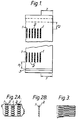
- Figure 1 shows, on scale about 1:3, an open-mouth pillow-bag, supplied with two shock-absorber-bands, one near the heat-seal at the bottom, and one at the top near the region predetermined for closing either by heat-sealing or by sewing.
- Figures 2A and B are details on about true scale of the bottom of the sack of Figure 1, A being a horizontal view of the bag, and B a longitudinal, vertical section passing through a row of indentations.
- Figure 3 is a modification of the shock-absorber-band of Figure 2A, also shown in horizontal view and on about true scale.
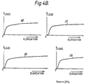
- Figure 4A are strain/stress diagrams taken on 5 specimens from the shock-absorber-band zone of a sack produced as described in Example 4.
- Figure 4B are strain/stress diagrams for comparison, taken on 5 specimens from the same sack, but outside the "shock-absorber-band" zone.
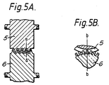
- Figures 5A and B show different sections of a set of embossment wheels (rollers) suitable for making the shock-absorber-band. Figure 5A is a section through b-b of Figure 5B, and Figure 5B is a section through a-a of Figure 5A.
-
- In Figures 1 through 3, (1) are rows of teeth-like indentations and (2) unaltered (or substantially unaltered) ribbons, (1) and (2) together forming the shock-absorber-band (hereinafter abbreviated to S-A-B). (3) is the heat-seal at the bottom. At the top, (4) indicates the zone where the bag is predetermined to become closed either by heat-sealing or by sewing. There are relatively long distances X1 and X2 from the S-A-B's to (3) and (4) respectively, the lengths of which will be discussed below.
- At each corner of the bag, a zone Y is preferably kept free of embossment. Y should be calculated so that it is sufficient to avoid any essential deformation when the filled bag is carried by the corners in the way by which it is intended to be handled.
- Edge-drop is by far the most critical kind of dropping for top - and bottom heat-seals or sewn seams in pillow bags. (For gussetted bags flat drop is more critical due to the special problem dealt with in connection with Figure 6, and for longitudinal seams bottom-drop and top-drop are most critical). When the edge of the bag filled with powder or granules hits the ground, the contents are with great force spread horizontally. At the moment the bag hits the ground, the spreading is confined to take place almost entirely perpendicularly to the length of the bag, and near top and bottom the impact on the flat surfaces of the bag then will cause a high longitudinal pull, that means strong peeling action on top and bottom seams. I have found that this peeling action is highest near the middle of the seams, or somewhat closer to the edge which hits the ground. It is very understandable that the peeling is near zero at the corners which do not hit the ground, but rather surprising that it also, is low near the corners which do hit the ground.
- The improvements achieved by use of the S-A-B are best understood by observation of the graphs in Figures 4A and B.
- The edges of each of the
specimens 11 to 14, of the invention, for the graphs in Figure 4A have been cut through the middle line of two unaltered ribbons (2) and each specimen comprises two rows of teethlike indentations (1) with an unaltered ribbon (2) between. In total therefore, each specimen consists of two rows of teethlike indentations (1) and two unaltered ribbons (2). The specimen width is 22mm. The initial distance between the jaws of the tensile testing apparatus is 50mm, and the specimen has S-A-B throughout this space. (The width of the S-A-B is also 50mm, see example 4.) The testing velocity is 500mm/min = 1000% elongation per min. In the graphs, 10mm on the abscissa corresponds to 20% elongation. - The comparative set of graphs Figure 4B was also made from 22mm
wide specimens 16 to 19 cut from parts of the sack that are free of shock absorber band. - In the range from zero to the deflexion point Y, the ribbons become elongated in elastical manner, but begin to yield at Y. In this range, comparison between the two sets of graphs shows that the slope in curves A is almost exactly half that of the curves B, in accordance with the fact that each ribbon in the S-A-B in this actual case (see example 4) has been made with the same width as each row of indentations, so that almost exactly half the width of the specimen is under load. The slope in this range is a measure of the coefficient of elasticity - for the embossed samples it is more correct to say apparent coefficient of elasticity - and the graphs demonstrate how the S-A-B makes the material appear more rubber-like.
- With the film composition used in example 4, the ratio between width of ribbon and division in the S-A-B could also have been somewhat higher than the actually used ratio 1:2 and still would have given satisfactory improvements, while it can be necessary to make the ratio much lower in case of much stiffer compositions, e.g., to make it 1:10 or even 1:20 (see example 1 in which it was necessary to use ratio 1:10).
- Between deflexion point Y and the next deflexion point A, the ribbons are yielding, while the indentations still are slack. At point A, the indentations are straightened out and begin to elongate elastically, while the ribbons continue yielding. At the last deflexion point B, the former indentations also start yielding.
- The elongation in percent at A is essentially equal to the original stretch ratio in the row of indentations, in this case about 28% equalling ratio 1.28:1.
- One important factor for the function of the S-A-B is the apparent reduction of coefficient of elasticity and yield point, dealt with above, which invites the impact to attack the S-A-B instead of attacking the seam. Another important factor is the energy absorbed by the S-A-B from zero to deflexion point B, which I call "S-A-B energy". This must be sufficiently big to "pacify" the impact caused by the edge drop, so that, after the S-A-B having been in effect, the attack on the seam will not be strong enough to ruin the latter.
- The indentations should preferably be made as deep as practically possible (i.e., the stretching ratio in the rows of indentations highest possible) so that the S-A-B energy per width of the S-A-B becomes highest possible (for any given pattern of embossment) however, there are the following practical limitations:
- (a) the limited stretchability of the film, in connection with the required high process.velocities,
- (b) the weakness of the teeth (fins) of the embossment devices.
-
- With the types of cross-laminates which are described in the examples, and which already have been stretched in both directions before the embossment in ratios between about 1.4:1 and 1.6:1, I have found it difficult to exceed ratios 1.3:1 or 1.4:1 when making the indentations, unless preheating of the film is used in the areas which are to be embossed, and normally I would avoid preheating which is a complication of the process. Stretch ratios lower than about 1.3:1 are also applicable when making the rows of indentations, provided at least 15%, but preferably more than 25% improvement in critical drop height of the bag (as this term is defined above) can be achieved.
- The optimum length of S-A-B and ratio between the width or each ribbon and the division in the S-A-B (total width of a ribbon and a row of indentations) must be established by systematical experiments or general experience, and depends, as already mentioned in the summary of the invention, on the performance requirements, the film characteristics, the dimensions of the bag, the material which will be filled into the bag, the degree of filing, the sealing or sewing process, and the temperature at which the drops are envisaged to take place. As regards performance requirements, the balance between the need for good drop performance and the need for form stability of the bag is particularly important.
- In Figures 1 to 3, the indentations are shown oblong, with their longitudinal direction perpendicular to the longitudinal direction of the ribbons (2). This structure will normally be advantageous, but it is also possible to substitute each oblong indentation with two or more generally circular indentations, although this will require more complicated apparatus for the embossment. In some cases, when only a small S-A-B effect is aimed at, single rows of generally circular indentations can be used in alternation with the ribbons (2).
- The division of the indentations in each row should preferably be as small as practically possible, the lower limit being determined by the obtainable strength of the teeth (ribs) in the apparatus for embossment and the practically obtainable accuracy of this apparatus. For bags from very thin film, this division can be down to about 1.5mm, while suitable values for heavy-duty bags generally are between about 2.0 - 4.0mm, although somewhat bigger divisions also are applicable.
- It has already been mentioned that the indentations must not start immediately adjacent to the seam (i.e., the distance x=0). In that case each ribbon (2) would pull almost with its full force on a corresponding portion of the seam, and practically no improvement would be achieved.
- In order to even out the forces on the seam, x should never be less, generally speaking, than about the same as the distance between two neighbour "ribbons", i.e., the width of each row of indentations, and preferably x should be a few times, e.g., 2 - 6 times this distance. X can also be longer, but since the tensions, when the bag hits the ground on edge, are concentrated near top and bottom, the entire S-A-B should generally be confined to a zone within a distance from the seam (or location predetermined to become seam) not exceeding 25% and preferably not exceeding 15% of the total length of the bag (or, in case the S-A-B is made for protection of the side-seam, of the width of the bag).
- In Figures 5A and B, both wheels (5) and (6) are driven with the same circumferential velocity, and the surfaces of both are formed as circular fins and grooves, the fins on one wheel fitting into the grooves of the other, with space left between for the bag material, so that the bag, when passing between the intermeshing fins, is stretched perpendicularly to the direction of advancing. While the fins on (5) are continuously circular, the fins on (6) are formed in dent-shapes as shown. All corners and edges which get into contact with the bag are carefully rounded and ground to avoid puncturing of the material.
- The bag is passed through the embossing device in a direction parallel to the top or bottom seam, whereby the top or bottom S-A-B shown in Figure 1 is formed. Both can of course be formed simultaneously by use of two sets of embossing wheels.
- At the inlet, the apparatus is preferably supplied with guide wheels (rollers) acting to keep the bag straightened out while counteracting the dragging towards the middle of the wheels (not shown).
- The set of wheels is preferably made to open and close, so that embossing can be avoided near each corner.
- The feeding of the bag into the device, and opening and closing of the wheels, can be done manually, semi-automatically or fully automatically. Immediately prior to the embossing and working in line with the wheels, there may be provided a pre-heating device which selectively heats the vicinity of the coming S-A-B. This can, e.g., be a device similar to a band-sealer, but operated at a temperature at which sealing does not occur. After the embossing, there may be a calendering step to reduce bulk.
- The device here described is the simplest and cheapest apparatus for producing the S-A-B. Alternatively, a press can be used having similar intermeshing fins, but of course in rectilinear instead of circular arrangement. This will be the apparatus normally used, if the process is carried out before bag-making.
- In the foregoing, the invention has been described with a view to sack applications, where the need is to build in shock-absorbing properties into a selected area near to a seam. However, it has been mentioned that there also can exist a need to modify a major proportion of or even the entire article, especially in connection with manufacture of parachutes. This applies in particular to cheap, disposable parachutes for parachuting of materials such as vehicles or containers. It is usually desirable that the unfolding of the parachute is postponed as much as possible, but the impact forces on the load and on the parachute itself when the parachute unfolds sets the limit for how late this can be.
- Therefore, parachutes are often supplied with shock-absorbing devices. The present invention, however, enables particularly efficient shock-absorption by simple and cheap means. Thus, the strapping can be made from film material (preferably assembled from several layers, which may be only loosely held together) which over a suitably long length is supplied with a pattern of stretched and unstretched zones according to the invention. Alternatively, the parachute cloth can be made from polymeric material which is supplied with a pattern of stretched and unstretched zones according to the invention over an essential part of its area, which may be almost the full area.
- The direction of the substantially unstretched zones in this pattern should preferably be mainly parallel to the local directions of force when the parachute unfolds and should preferably be in the form of a plurality of ribbons.
- It is well known that orientable polymers, especially the highly crystaline and stiff ones such as high density polyethylene or polypropylene, exhibit high yield point and at the same time, if drawn slowly, a high elongation at break (up to about 10 times) and a high ultimate tensile strength. Therefore, the energy absorption up to the breaking point is also very high when the polymers are slowly drawn, but during very quick drawing they may rupture almost without any permanent deformation. By application of the present invention, the physical characteristics can be changed very significantly so that, even under the worst impact conditions, a permanent deformation can start at almost zero tension and progress in predetermined way under increasing resistance to a high degree of elongation and to a force close to the ultimate tensile force obtained during slow drawing.
- Especially for these uses, the substantially unstretched ribbons should preferably be very narrow, and the degree of stretching in the individual boss on the film very smoothly varied from zero at the boundary of the ribbon to the maximum value near the middle of the boss between two ribbons.
- Material very suited for such strapping is high density polyethylene and polypropylene, which both may be used unblended. For the parachute cloth (or hood) one can use cross-laminates of the biaxially oriented type and generally similar composition as the sack material used in examples 3 and 4. Additionally, the blends can contain polypropylene.
- This example demonstrates the improvements achieved with shock-absorber-band on heat-sealed pillow-bags from polypropylene-based, biaxially oriented cross-laminates at 0°C. At this temperature, the heat-seal will act so fragile without a S-A-B, that such materials cannot be used for heavy duty bags with simple heat-seals.
- A cross-laminate based on gas-phase-type polypropylene was produced generally as in Example 2 of my U.K. patent no.1,526,722 and the corresponding U.S. patent no.4,039,364, however with the following essential differences:
- (a) 4-ply instead of 3-ply, with the angles of main direction: +45°, +30°, -30°, -45°.
- (b) Gauge 90gsm instead of 72gsm.
- (c) The admixture to the polypropylene in the middle layer of the coextruded film was 20% lineary low density polyethylene (LLDPE) instead of 14%EVA.
- (d) The surface layers of the coextruded film were blends of polypropylene and ethylene-propylene-dimer rubber (EPDM) instead of EVA.
-
- The cross-laminate was tubed by use of an extruded melt-adhesive for the side-seam, and the tube was cut into lengths of about 1.0m. Flat width: 500mm. The side-seam was positioned very close to the edge. The bottom seams for the open-mouth bags were produced manually by impulse-sealing. In order to allow shrinkage to take place in the heat-seal and thereby a growth of its thickness, the cooling period in the sealing process was set at zero, so that all cooling took place after release of the pressure on the jaws.
- The reason for placing the side-seam very close to one edge is that I have found the intersection between heat-seal and side-seam most prone to start of tearing along the heat-seal (on edge-dropping). More correctly, the weak zone is not in the side-seam itself, but immediately adjacent to the latter, where the seal is inadequate. It was hypothetically assumed that the edge drop causes only low peel-forces near the edge which hits the ground compared to the peel forces at the middle of the seal - and of course the peel forces will be nearly zero near the other edge - so it was assumed that highest "critical drop height" is achieved with the side-seam near to one of the edges. The proof hereof is given in Example 2.
- Each bag was filled with 25kg polyethylene granules, and a piece of the top was cut off to leave about 11 - 12cm free space over the evened-out level of the contents (bag standing upright, major bag faces folded over the level of the contents to the middle, free space measured hereover). The bag was closed by overtaping with reinforced adhesive tape. In practical production it should be closed either by heat-sealing or sewing, and a S-A-B provided also at the top, but it was judged that the effect of the S-A-B per se best can be determined by investigations only of such heat-seals or sewn seams which are made prior to filling.
- The drop-testing was carried out at ambient temperature 0°C, and the contents of the bags (the polyethylene granules) were precooled to this temperature.
- In a series of initial trials, the applicable ratios between widths of "unaltered ribbons" and "rows of indentations" were determined as follows: A primitive laboratory press was made for embossment of one row only of indentations, consisting of 15 single indentations, each 10mm long, with row division (distance between top of two neighbour indentations) being 3.0mm. The S-A-B was made from edge to edge by repetition of embossment, row by row. The "ribbons" were kept at constant width within each bag, but different ribbon-widths were tried. The stretching ratio, corresponding to the depth of embossment, is believed to have been about 1.20:1, and in any case was the same for all embossments. The S-A-B was started 30mm from the heat-seal.
- It was found that the width of the "ribbons" had to be down at about 2mm to give a significant improvement, and 1mm was estimated to be the optimum.
- An embossing apparatus as shown in Figures 5A and B was made for ribbon-width 1.mm, row-width 10.mm, row-length (= width of the S-A-B) is 50mm, division of each row 3.mm, and 17 indentations in each row. Start of S-A-B 30mm from the heat-seal. It extended the width of the bag.
- The embossment was carried out at room temperature, with the fins of the wheels practically in full engagement (exactly the same engagement in all trials) which is believed to have corresponded to stretch ratio about 1.2:1.
- The strength of the heat-seal with and without embossment was determined as the critical drop height, which statistically, is the limit between no-failure and failure, when one bag with the relevant contents is dropped 6 timed in the following cycle: (1) 1st flat surface, (2) 2nd flat surface, (3) 1st edge, (4) 2nd edge, (5) bottom, (6) top.
- However in order to simplify the testing work for heat-sealed pillow-bags, the determination has been modified so that only one drop is carried out per bag, namely an edge -drop on the edge closest to the side seam. The justification for this simplification is my experience (confined to the biaxially stretched type of cross-laminates) that when a bag has passed one edge-drop, the weak, disoriented line adjacent to the heat-seal will be reinforced by an orientation caused by the drop. Therefore, subsequent drops from the same height will in any case give positive results and are needless. Further, drops (1) and (2) of the above-mentioned cycle (the flat drops) have been found, practically speaking, neither to weaken nor to reinforce the heat-seal of a pillow bag. This simplification of testing procedure is not applicable to gussetted, neither to sewn bags.
- Table of results, indicating for each trial, drop height in cm, and passed = P or failed = F.
Without SAB With SAB Bag No. Drop Height Result Bag No. Drop Height Result 1 160 F 3 250 F 4 140 P 15 240 P 5 140 F 17 240 P 12 120 F 16 240 F 13 120 F 6 220 F 14 120 F 7 200 P 18 100 F 8 200 P 19 100 F 9 200 P 10 200 F 11 200 P 2 190 P - Since only one bag without S-A-B has passed, namely no. (4) from 140cm, while 3 bags from 120cm and 2 from 100cm have failed, it is believed that no.4 was not a straight edge drop but should be discarded. The critical edge drop value therefore will be lower than 100cm for the bag without S-A-B, while it is estimated to be about 220cm for the bag with S-A-B.
- The objective of this example is an elaborate drop-strength comparison at room temperature between heat-sealed bags with and without S-A-B, made from biaxially oriented cross-laminates of two different compositions, one based on polypropylene, and the other on polyethylene. In each case, drop-test comparison are also made between bags having the side-seam 15cm from an edge, and bags with the side seam adjacent to an edge. The polypropylene-based cross-laminate was a similar 4-ply as in Example 1, except that the addition to the polypropylene in the middle layer of the coextruded film now was 10% EPDM. The gauge still was 90gsm. The polyethylene-based cross-laminate was a combination of high-molecular-weight-high-density-polyethylene (HMHDPE) and lineary low density polyethylene (LLDPE), namely the 2-ply cross-laminate designated as "R1" in Example 3 of U.S. patent no.4,629,525.
- Tubing and bag making was carried out like in example 1. The bag width was 490mm for the polypropylene-based bags and 560mm for the polyethylene-based bags.
- The pattern of S-A-B, its distance from the heat-seal, the embossment apparatus and the engagement between the fins of the latter were also exactly as in Example 1. The S-A-B extended the bag width. It is believed that the stretch ratio has been about 1.20:1.
- The bags were filled with 50kg of PVC granules plus sand, and the top closure was made with a self-adhesive reinforced tape like in Example 1.
- Free space 11 - 12cm like in Example 1.
- The critical drop height was determined in the same simplified manner as in Example 1.
- In the table below:
- Film Type A is polypropylene 90 gsm
- Film Type B is polyethylene 70 gsm
- Sack Type S is a bag without SAB and side seam 15 cm from edge
- Sack Type C is a similar bag to S but with side seam at corner
- Sack Type C + SAB is a similar bag to C but with one SAB
- Sack Type C + 2SAB is a similar bag to C but with two SAB
- Edge Drop Tests recorded the height of drop and whether the sack passed P failed F, just failed (F) with a split below 10mm or split at the SAB, probably due to puncture during the embossing (F*)
-
- The seal is formed by a Star Impulse Sealer at the Weld Time and Heat Rating Settings quoted, except for the two series sealed with a Doboy Band Sealer.
- As it appears from the table, the move of the side-seam to the edge generally lead to about 50% improvement of the critical drop height, and the use of S-A-B further lead to about 50% improvement. Use of a second S-A-B close to the first one gave no significant extra improvement.

- The objective of this example is to investigate the improvements in drop-performance of gussetted bags by use of the "Gussett Embossment" alone and in combination with the S-A-B. The material for the bags investigated was the "R1" cross-laminate also used in example 2, except that the LLDPE of example 2 has been the octene copolymer of ethylene, but in this example was its copolymer with butene. The guage of the cross-laminate now was 80 gam. Tubing was carried our as in example 1, the tube width being, 56cm before gussetting. A 50mm deep gusset was folded by hand, and heat-sealed bags made by use of impulse sealing. The conditions for sealing were optimized and no cooling period applied. The sealing conditions were the same for all bags tested.
- The Gusset Embossment was carried out on the tube before gussetting, while the S-A-B pattern was embossed into the laminate after gussetting.
- For both types of embossment, the same embossment wheels, and the same pattern was used as in examples 1 and 2, with the modification that the wheels now were tightly screwed towards each other to increase the stretch ratio. A depth of embossment was measured corresponding to stretch ratio about 1.30 : 1. The heat-seal was made about 20cm from the start of the Gusset Embossment, and the S-A-B, which comprised gusset as well as outer faces of the bag, was embossed immediately adjacent to the Gusset Embossment on the side of the latter which was opposite to the heat-seal.
- It should be born in mind (see example 1) that the width of "unaltered ribbons" were 1.0mm, width of rows of indentations 10 mm, and width of the S-A-B (now also of the Gusset Embossment) 50 mm.
- The bags were filled with 50 kg salt (sodium chloride). At the top, the gusset was straightened out to give the bag its full width 56 cm, and the bag was closed with a reinforced self adhesive tape. Free space over the level of contents was 10 cm.
- The following test-cycle was applied: (1) flat drop one side, (2) flat drop on the other side, (3) drop on one edge, (4) drop on the other edge. It was considered needless to carry out bottom and top-drops, since the latter would not cause or further develop ruptures.
- The first bag tasted was without any embossment, neither Gusset Embossment nor S-A-B. It was dropped flat from 90 cm height and the first drop produced a split about 10 cm long at each of the two critical locations (the junctions between the side gusset and the seam). The drop cycle was interrupted after this first drop.
- A second bag tested was with out Gusset Embossment and S-A-B, and was tried in the above mentioned cycle of four drops from 400 cm. After the two flat drops there was observed very small tears at the two critical locations, and after the subsequent two edge-drops the length of tearing was measured to be 10mm and 12 mm.
- A third bag, also with both Gusset Embossment and S-A-B was tested in the same cycle of four drops, but from 300 cm. There occured no tearing at all.
- It is therefore judged that the Gusset Embossment and S-A-B together has improved the performance of the bag by a factor higher than four.
- A fourth bag was produced with the Gusset Embossment, but without S-A-B and was tested in one single flat drop from 400 cm. There was observed a 5mm tear at one and a 8mm tear at the other critical location which in any case is less than the damage of bag no. 1 tested from 90 cm only and also on one flat drop only.
- As an interesting further feature of the bags with Gusset Embossment, it was observed that the filled bag exhibited clearly better block shape at the bottom than the gussetted sacks with the Gusset Embossment.
- The objective of this example is to demonstrate the improvements which the S-A-B causes in a bag with sewn top and/or bottom seam.
- The bags were made from the biaxially oriented cross-laminate, which which is designated as "R2" in example 3 of U.S. patent no. 4.629.525. This is stiffer than "R1" used in examples 2 and 3, and connected with this higher stiffness exhibits a higher tear propagation resistance. For further improvements of stitching strength, the spiral cutting angle 45° used in the mentioned example of the U.S. patent, was substituted by spiral cutting angle 30°. The stretching and lamination of the plies were carried out by the improved method described in example 3 of my copending PCT application PCT/GB88/00027. The stretch ratios were 1.40 : 1 in both directions, and guage 70 gsm.
- Tubing was carried out as in example 1, to give bag width 56cm. The side seam was positioned 6-7cm from the edge, which was the closest that could be made continuously on the tubes actually used. The bottom of the bag sewn, while using over-folding of the bag material in the seam and over-taping with crepe paper. The distance between the stitches was 8 mm.
- The S-A-B was embossed in the pattern and by the apparatus described in example 1, except that the pattern was modified so that "ribbon" width equaled "indentation" length, but still giving the same total, namely 11mm (the division of the S-A-B), and the S-A-B was still 50 mm wide. This change of embossment pattern was made, not particularly because sewing should be applied, but because the other pattern, which was developed for a polypropylene composition, was considered less suitable for the polyethylene composition.
- Strain/stress diagrams taken in the S-A-B are shown in Figure 4A and similar diagrams from the unembossed cross-laminate in Figure 4B. Comparison between these diagrams and explanation of the significance are given in the description of these figures. As mentioned here, it appears from Figure 4A that the stretch ratio in the rows of indentations has been 1.28:1, a value which also with approximation is estimated from the observed shape and measured dimensions of the indentations.
- The bags were filled with 20kg polyethylene granules and closed by overtaping with reinforced seld adhesive tape. The free space between the top level and the closure, measured as indicated in example 1, was 11-12 cm.
- Four bags with, and four without, S-A-B were drop-tested around the values which beforehand were judged to be their critical drop heights. There was used the same drop-test cycle as in example 3. By these trials, the bags without S-A-B were estimated to have critical drop height 120cm and the bags with S-A-B 250 cm.
- If bags are under a particularly high pressure in a stack, the S-A-B can conceivably become stretched so much that the embossment disappears, but the latter will be to some extend revert when the pressure has been released. Further, the stretching caused by the pressure will have oriented the disoriented weak line adjacent to the heat-seal (in the case of heat-sealed bags) so that the seam in any case is reinforced. With properly selected dimensions for the S-A-B, the deformation when the embossment disappears, will not be serious for the quality of stacking. Thus, in all of the examples, full force to eliminate the embossment will cause only 20-30% elongation of a 5 cm wide S-A-B, or with one S-A-B at top and one at bottom, a total elongation of about or less than 3 cm. Since normal length for a 50 kg bag is about 1.0m or slightly less, the total elongation of the bag caused by full stretching-out of the two S-A-B's will be about 3-4% at the highest, all provided the need for S-A-B effect does not exceed the improvements which have been demonstrated by these examples.
Claims (11)
- A parachute comprising a hood and strapping for carrying a load in which the strapping or the hood is formed from oriented thermoplastic polymeric film material having a shock absorbing zone comprisingat least one stretched zone that extends in a direction parallel to local directions of force upon unfolding of the parachute in use in which the film material has been stretched substantially in that direction andat least one substantially unstretched zone adjacent to each side of and extending in substantially the same direction at the or each stretched zone, whereby the forces are transmitted away from the or each stretched zones into the unstretched zone or zones.
- A parachute according to claim 1 in which the or each stretched zone comprises a series of positions extending transversely to said direction at which the film material is longitudinally stretched.
- A parachute according to claim 2 in which the stretching is by embossing with teeth that extend transversely to the first direction.
- A parachute according to any preceding claim in which there are a plurality of stretched zones alternating with the plurality of unstretched zones.
- A parachute according to claim 4 in which the degree of longitudinal stretch varies smoothly in the transverse direction from zero at the transverse edges of the stretched zone to the maximum value near the mid-line between those edges.
- A parachute according to any preceding claim in which the said material forms strapping for said parachute.
- A parachute according to claim 6 in which the strapping is formed from several layers of said film material, which are loosely held together.
- A parachute according to claim 6 or claim 7 in which the polymeric material comprises unblended high density polyethylene or polypropylene.
- A parachute according to any preceding claim in which the said material forms the hood of the parachute and in which the unstretched and stretched zones extend substantially the entire area of the hood.
- A parachute according to any preceding claim in which the film material has a rupture zone in which rupture is liable to occur during use of the parachute, in which the film material adjacent the rupture zone includes the shock absorbing zone.
- Use of a parachute according to any of claims 1 to 10 to support a load in which the shock absorbing zone reduces the forces on the load.
Applications Claiming Priority (3)
| Application Number | Priority Date | Filing Date | Title |
|---|---|---|---|
| GB8809077 | 1988-04-18 | ||
| GB888809077A GB8809077D0 (en) | 1988-04-18 | 1988-04-18 | Polymeric bags & methods & apparatus for their production |
| EP89303774A EP0338747B1 (en) | 1988-04-18 | 1989-04-17 | Polymeric film material and its production |
Related Parent Applications (2)
| Application Number | Title | Priority Date | Filing Date |
|---|---|---|---|
| EP89303774.7 Division | 1989-04-17 | ||
| EP89303774A Division EP0338747B1 (en) | 1988-04-18 | 1989-04-17 | Polymeric film material and its production |
Publications (3)
| Publication Number | Publication Date |
|---|---|
| EP0665161A2 EP0665161A2 (en) | 1995-08-02 |
| EP0665161A3 EP0665161A3 (en) | 1995-11-15 |
| EP0665161B1 true EP0665161B1 (en) | 1999-03-10 |
Family
ID=10635358
Family Applications (3)
| Application Number | Title | Priority Date | Filing Date |
|---|---|---|---|
| EP89303774A Expired - Lifetime EP0338747B1 (en) | 1988-04-18 | 1989-04-17 | Polymeric film material and its production |
| EP95104279A Expired - Lifetime EP0665161B1 (en) | 1988-04-18 | 1989-04-17 | Parachute materials |
| EP19890904848 Pending EP0411007A1 (en) | 1988-04-18 | 1989-04-17 | Polymeric film material and its production |
Family Applications Before (1)
| Application Number | Title | Priority Date | Filing Date |
|---|---|---|---|
| EP89303774A Expired - Lifetime EP0338747B1 (en) | 1988-04-18 | 1989-04-17 | Polymeric film material and its production |
Family Applications After (1)
| Application Number | Title | Priority Date | Filing Date |
|---|---|---|---|
| EP19890904848 Pending EP0411007A1 (en) | 1988-04-18 | 1989-04-17 | Polymeric film material and its production |
Country Status (25)
| Country | Link |
|---|---|
| US (2) | US5205650A (en) |
| EP (3) | EP0338747B1 (en) |
| JP (1) | JP2632583B2 (en) |
| CN (1) | CN1032800C (en) |
| AT (2) | ATE177385T1 (en) |
| AU (1) | AU637047B2 (en) |
| BR (1) | BR8907379A (en) |
| CA (1) | CA1332024C (en) |
| DE (2) | DE68924865T2 (en) |
| DK (1) | DK174940B1 (en) |
| ES (1) | ES2082773T3 (en) |
| FI (1) | FI905114A0 (en) |
| GB (1) | GB8809077D0 (en) |
| GR (1) | GR3019032T3 (en) |
| HK (1) | HK1007543A1 (en) |
| HU (1) | HU216745B (en) |
| IE (1) | IE72159B1 (en) |
| IN (1) | IN174401B (en) |
| MX (1) | MX169245B (en) |
| MY (1) | MY104990A (en) |
| NO (1) | NO302876B1 (en) |
| PT (1) | PT90306B (en) |
| RU (2) | RU2117608C1 (en) |
| WO (1) | WO1989010312A1 (en) |
| ZA (1) | ZA892795B (en) |
Families Citing this family (95)
| Publication number | Priority date | Publication date | Assignee | Title |
|---|---|---|---|---|
| GB8809077D0 (en) * | 1988-04-18 | 1988-05-18 | Rasmussen O B | Polymeric bags & methods & apparatus for their production |
| US6358234B1 (en) | 1990-01-23 | 2002-03-19 | The Procter & Gamble Company | Absorbent article having deformed hinge and zones of extensibility |
| US9604429B2 (en) | 2010-11-16 | 2017-03-28 | The Glad Products Company | Ribbed film structures with pigment created visual characteristics |
| US9566760B2 (en) | 2010-11-16 | 2017-02-14 | The Glad Products Company | Ribbed film structures with voiding agent created visual characteristics |
| US9393757B2 (en) | 2010-11-16 | 2016-07-19 | The Glad Products Company | Discontinuously laminated film structures with improved visual characteristics |
| US5531393A (en) * | 1992-05-19 | 1996-07-02 | Salzsauler; Donald J. | Stretch film |
| US5518801A (en) * | 1993-08-03 | 1996-05-21 | The Procter & Gamble Company | Web materials exhibiting elastic-like behavior |
| US5916663A (en) * | 1993-08-03 | 1999-06-29 | Chappell; Charles W. | Web materials exhibiting elastic-like behavior |
| US5891544A (en) * | 1993-08-03 | 1999-04-06 | The Procter & Gamble Company | Web materials exhibiting elastic-like behavior |
| CZ78696A3 (en) * | 1993-09-20 | 1996-10-16 | Procter & Gamble | Absorption article |
| BR9408106A (en) * | 1993-11-19 | 1997-08-05 | Procter & Gamble | Disposable absorbent article and disposable diaper |
| US5554145A (en) * | 1994-02-28 | 1996-09-10 | The Procter & Gamble Company | Absorbent article with multiple zone structural elastic-like film web extensible waist feature |
| US6391404B1 (en) | 1995-06-07 | 2002-05-21 | Baxter International Inc. | Coextruded multilayer film materials and containers made therefrom |
| US6083584A (en) * | 1998-01-30 | 2000-07-04 | Baxter International Inc. | Perimeter seals for multi-layer materials and method |
| FR2742416B1 (en) * | 1995-12-13 | 1998-02-06 | Thimon | PRE-STRETCHED FILM, DEVICE AND METHOD FOR OVERPACKING |
| US6344258B1 (en) * | 1996-11-22 | 2002-02-05 | Ole-Bendt Rasmussen | Heat-sealing polymer films |
| JP4088354B2 (en) * | 1997-02-27 | 2008-05-21 | 株式会社日立グローバルストレージテクノロジーズ | Information recording / reproducing device |
| USH2042H1 (en) * | 1997-05-09 | 2002-08-06 | The Procter & Gamble Company | Method for forming a breathable film |
| US6056241A (en) * | 1997-08-14 | 2000-05-02 | Ballistic Recovery Systems, Inc. | Thin film parachute with continuous lateral reinforcing fibers |
| US6046521A (en) * | 1998-01-20 | 2000-04-04 | Camco International, Inc. | Electric submergible motor protector having collapse resistant ribbed elastomeric bag |
| EP0963835A1 (en) * | 1998-05-05 | 1999-12-15 | The Procter & Gamble Company | Discontinuously expandable web materials |
| US6391411B1 (en) * | 1999-06-03 | 2002-05-21 | Printpack Illinois, Inc. | Machine direction oriented high molecular weight, high density polyethylene films with enhanced water vapor transmission properties |
| US6220547B1 (en) | 1999-06-08 | 2001-04-24 | Pioneer Aerospace Corporation | Large scale parafoil apparatus with an energy attenuator for controlling initial deployment |
| US6394651B2 (en) * | 1999-06-18 | 2002-05-28 | The Procter & Gamble Company | Flexible bags having enhanced capacity and enhanced stability in use |
| US6150647A (en) * | 1999-06-18 | 2000-11-21 | The Procter & Gamble Company | Flexible, cushioned, high surface area food storage and preparation bags |
| US6394652B2 (en) | 1999-06-18 | 2002-05-28 | The Procter & Gamble Company | Flexible bags having stretch-to-fit conformity to closely accommodate contents in use |
| AU5752200A (en) * | 1999-06-18 | 2001-01-09 | Procter & Gamble Company, The | High surface area insulating films |
| AU5627400A (en) * | 1999-06-18 | 2001-01-09 | Procter & Gamble Company, The | Cushioned, stretchable packaging materials |
| CN1356949A (en) * | 1999-06-18 | 2002-07-03 | 宝洁公司 | Conformable container liners |
| US6220753B1 (en) | 1999-08-04 | 2001-04-24 | Michael A. Metzger | Plastic liner bag with mouth retaining means |
| US6513975B1 (en) * | 2000-06-19 | 2003-02-04 | The Procter & Gamble Company | Bag with extensible handles |
| GB0114691D0 (en) | 2001-06-15 | 2001-08-08 | Rasmussen O B | Laminates of films and methods and apparatus for their manufacture |
| US6966697B2 (en) * | 2002-02-22 | 2005-11-22 | Pactiv Corporation | Trash bags with narrowing seals to facilitate gripping |
| US7179344B1 (en) * | 2002-04-08 | 2007-02-20 | Lako Tool & Manufacturing, Inc. | Method and apparatus for testing the quality of crimped seals |
| US6979482B2 (en) * | 2002-11-08 | 2005-12-27 | Exopack-Technology, Llc | Multiwall bag with zipper and fin |
| US7090904B2 (en) * | 2002-11-08 | 2006-08-15 | Exopack, L.L.C. | Enhanced slider zipper multiwall bag and associated methods |
| US6938309B2 (en) * | 2002-12-13 | 2005-09-06 | 3M Innovative Properties Company | Zoned stretching of a web |
| JP5106776B2 (en) * | 2002-12-13 | 2012-12-26 | ラスムッセン・オーレ−ベント | Film laminate having improved durability against bending in all directions, and method and apparatus for manufacturing the same |
| US7938635B2 (en) | 2002-12-20 | 2011-05-10 | The Procter & Gamble Company | Apparatus for producing a web substrate having indicia disposed thereon and elastic-like behavior imparted thereto |
| NZ543147A (en) | 2003-04-24 | 2007-09-28 | Rasmussen O B | Method of manufacturing oriented films from alloyed thermoplastic polymers, apparatus for such manufacture and resulting products |
| US20050178493A1 (en) * | 2004-02-18 | 2005-08-18 | Broering Shaun T. | Method and apparatus for making flexible articles having elastic-like behavior with visually distinct regions |
| WO2006015095A2 (en) * | 2004-07-28 | 2006-02-09 | Sanford Redmond | Stress relieving indent formation for very thin thermoformed plastic films or foil/plastic laminates |
| GB0424355D0 (en) * | 2004-11-03 | 2004-12-08 | Rasmussen O B | Improved method of manufacturing an alloyed film apparatus for the method and resultant products |
| GB0426839D0 (en) * | 2004-12-07 | 2005-01-12 | Rasmussen O B | Small container made from thermoplastic sheet material |
| EP1843897B1 (en) | 2005-01-07 | 2012-03-21 | Ole-Bendt Rasmussen | Laminate of thermoplastic film materials exhibiting throughgoing porosity and process for forming it |
| US20060165319A1 (en) * | 2005-01-21 | 2006-07-27 | Pactiv Corporation | Polymeric bags with narrowing seals |
| ATE422410T1 (en) * | 2005-04-08 | 2009-02-15 | Ole-Bendt Rasmussen | METHOD AND DEVICE FOR FILM EXTRUSION |
| KR20080012351A (en) | 2005-05-11 | 2008-02-11 | 올레-벤트 라스무쎈 | Crosslaminate of oriented films and methods and apparatus for manufacturing same |
| US20070012589A1 (en) * | 2005-07-15 | 2007-01-18 | Cassoni Robert P | Process for manufacture of a flexible package |
| US7607357B2 (en) | 2006-03-02 | 2009-10-27 | Enepay Corporation | Automated test systems configured to evaluate properties of packaging film and related methods |
| WO2007106297A2 (en) * | 2006-03-02 | 2007-09-20 | Enepay Corporation | Automated packaging-film testing systems with efficient loading configurations and operation |
| FR2907116B1 (en) * | 2006-10-16 | 2008-12-19 | Saint Gobain Ct Recherches | FRITTE PRODUCT BASED ON ZIRCON + NB2O5 OR TA2O5 |
| US7942577B2 (en) | 2006-12-12 | 2011-05-17 | The Procter & Gamble Company | Flexible bag having a drawtape closure |
| US20100040875A1 (en) * | 2006-12-29 | 2010-02-18 | Dow Global Technologies Inc. | Films, articles prepared therefrom, and methods of making the same |
| US7820566B2 (en) * | 2007-05-21 | 2010-10-26 | Automotive Technologies International, Inc. | Film airbags |
| US8822357B2 (en) * | 2007-05-21 | 2014-09-02 | Automotive Technologies International, Inc. | Film airbags made from ribbons |
| US20090094943A1 (en) * | 2007-10-10 | 2009-04-16 | The Procter & Gamble Company | Absorbent article package with enhanced grip |
| GB0814308D0 (en) * | 2008-08-05 | 2008-09-10 | Rasmussen O B | Film material exhibiting textile properties, and method and apparatus for its manufacture |
| TWI499497B (en) | 2008-01-17 | 2015-09-11 | Ole-Bendt Rasmussen | Film material exhibiting textile properties, and method and apparatus for its manufacture |
| US9604760B2 (en) | 2008-08-25 | 2017-03-28 | The Glad Products Company | Bag |
| US20100098354A1 (en) * | 2008-10-20 | 2010-04-22 | Fraser Robert W | Bag and Methods of Making the Same |
| US9637278B2 (en) * | 2008-10-20 | 2017-05-02 | The Glad Products Company | Non-continuously laminated multi-layered bags with ribbed patterns and methods of forming the same |
| US8888365B2 (en) * | 2009-11-16 | 2014-11-18 | The Glad Products Company | Non-continuously laminated multi-layered bags |
| US9016945B2 (en) | 2008-10-20 | 2015-04-28 | The Glad Products Company | Bag and method of making the same |
| US10023361B2 (en) | 2009-05-26 | 2018-07-17 | The Glad Products Company | Draw tape bag |
| GB0911822D0 (en) | 2009-07-08 | 2009-08-19 | Rasmussen O B | Gas filled crosslaminate and method and apparatus for its manufacture |
| US8794835B2 (en) * | 2009-09-03 | 2014-08-05 | The Glad Products Company | Draw tape bag |
| US9522768B2 (en) | 2009-09-03 | 2016-12-20 | The Glad Products | Draw tape bag |
| US9050783B2 (en) * | 2009-11-16 | 2015-06-09 | The Glad Products Company | Multi-layered bags with shortened inner layer |
| US9114596B2 (en) | 2009-11-16 | 2015-08-25 | The Glad Products Company | Incrementally-stretched adhesively-laminated films and methods for making the same |
| US8940377B2 (en) * | 2009-11-16 | 2015-01-27 | The Glad Products Company | Multi-layered bags with discrete non-continuous lamination |
| US10293981B2 (en) | 2009-11-16 | 2019-05-21 | The Glad Products Company | Non-continuously laminated structures of thermoplastic films with differing material compositions and functional material properties |
| US9272459B2 (en) | 2010-03-10 | 2016-03-01 | The Glad Products Company | Bag |
| US9272461B2 (en) * | 2010-03-10 | 2016-03-01 | The Glad Products Company | Bag |
| EP3058878B1 (en) | 2010-09-09 | 2019-07-17 | W. L. Gore & Associates, Inc. | Method of increasing film tear strength |
| CA2832649C (en) * | 2011-04-25 | 2018-11-20 | The Glad Products Company | Thermoplastic films with visually-distinct stretched regions and methods for making the same |
| CN204222116U (en) * | 2011-04-25 | 2015-03-25 | 格拉德产品公司 | Multilayer film |
| WO2013027104A1 (en) * | 2011-08-25 | 2013-02-28 | Db Equipment As | Accessory bag having reinforced sidewalls and variable length |
| EP2639063B1 (en) * | 2012-03-15 | 2016-12-14 | pely-plastic GmbH & Co. KG | Material with embossments |
| US9707421B2 (en) | 2013-02-08 | 2017-07-18 | D B Industries, Llc | Energy absorber cover |
| CN105189089A (en) | 2013-03-13 | 2015-12-23 | 爱默思公司 | Manufacturing process for packaged pet food |
| WO2014140380A1 (en) * | 2013-03-15 | 2014-09-18 | Ole-Bendt Rasmussen | A method of manufacturing a strainable thermoplastic film material, product resulting therefrom, and apparatus to carry out the method |
| US9212520B1 (en) * | 2013-08-26 | 2015-12-15 | The United States Of America As Represented By The Secretary Of The Navy | End guide for cord attachment device |
| US9290303B2 (en) | 2013-10-24 | 2016-03-22 | Poly-America, L.P. | Thermoplastic films with enhanced resistance to puncture and tear |
| US9546277B2 (en) | 2013-10-24 | 2017-01-17 | Poly-America, L.P. | Thermoplastic films and bags |
| US9517862B2 (en) * | 2014-04-02 | 2016-12-13 | Poly-America, L.P. | Thermoplastic bag |
| US10138054B2 (en) * | 2015-03-17 | 2018-11-27 | Poly-America, L.P. | Polymeric bags |
| JP2018520038A (en) * | 2015-06-03 | 2018-07-26 | エックス デベロップメント エルエルシー | Hard point strain relief |
| US9919868B2 (en) | 2015-10-30 | 2018-03-20 | Inteplast Group Corporation | Receptacle liner |
| CN105328922A (en) * | 2015-11-23 | 2016-02-17 | 安徽国泰印务有限公司 | PETG membrane production technology |
| CA2959423A1 (en) * | 2016-03-10 | 2017-09-10 | Flexopack S.A. | Liner film |
| AU2018365773A1 (en) * | 2017-11-08 | 2020-05-21 | The Glad Products Company | Films and bags having low-force extension patterns |
| US11040778B2 (en) * | 2018-11-16 | 2021-06-22 | Goodrich Corporation | Multi-staged suspension line attenuator |
| CN110171162A (en) * | 2019-06-21 | 2019-08-27 | 山东新华医疗器械股份有限公司 | A kind of soft bag bag-making method and products thereof |
| KR20230104944A (en) * | 2020-11-12 | 2023-07-11 | 엔젤케어 캐나다 인코포레이티드 | Envelope construction for tins |
Family Cites Families (41)
| Publication number | Priority date | Publication date | Assignee | Title |
|---|---|---|---|---|
| US2083352A (en) * | 1930-12-18 | 1937-06-08 | Smithe Machine Co Inc F L | Embossing means for envelope making machines |
| FR842665A (en) * | 1938-02-18 | 1939-06-16 | Parachute training | |
| US2161820A (en) * | 1938-05-10 | 1939-06-13 | Gregory J Kessenich | Shock absorbing device |
| US2471166A (en) * | 1944-10-16 | 1949-05-24 | Edward A Neff | Shock absorber webbing |
| US2422440A (en) * | 1945-04-19 | 1947-06-17 | Stanley Switlik | Parachute and elastic suspension line |
| US2474124A (en) * | 1946-03-08 | 1949-06-21 | All American Airways Inc | Parachute leader |
| US2723936A (en) * | 1952-05-06 | 1955-11-15 | Continental Can Co | Knurled seam and method of forming the same |
| US2878013A (en) * | 1956-11-22 | 1959-03-17 | Piodi Roberto | Jerk absorber for tow ropes and similar flexible members |
| US3018015A (en) * | 1957-10-02 | 1962-01-23 | Agriss Norton | Resilient packing sheet |
| US3232516A (en) * | 1963-11-08 | 1966-02-01 | Ex Cell O Corp | Paperboard container |
| US3393861A (en) * | 1966-11-29 | 1968-07-23 | Mobil Oil Corp | Embossed thermoplastic bags |
| US3495761A (en) * | 1968-04-16 | 1970-02-17 | Hudson Pulp & Paper Corp | Embossed kraft paper and paper bags made therefrom |
| US3605374A (en) * | 1969-04-02 | 1971-09-20 | American Can Co | Method of making multi-unit packages |
| FR2080004A5 (en) * | 1970-02-19 | 1971-11-12 | Johnson & Johnson | Thermoplastic film or sheet with ribs for - container production |
| US3904465A (en) * | 1970-02-20 | 1975-09-09 | Mobil Oil Corp | Process and apparatus for the manufacture of embossed film laminations |
| SE345966B (en) * | 1970-04-23 | 1972-06-19 | Goeteborga Bandvaeveri | |
| US3743172A (en) * | 1971-03-23 | 1973-07-03 | Mobil Oil Corp | Quilted laminar films comprising at least two layers of dissimilar material |
| US3760940A (en) * | 1971-07-02 | 1973-09-25 | Mobil Oil Corp | Method of embossing thin, limp plastic film, and disposable and embossed plastic bag product |
| US4000352A (en) * | 1972-06-01 | 1976-12-28 | W. R. Grace & Co. | Battery separator |
| US3832267A (en) * | 1972-09-19 | 1974-08-27 | Hercules Inc | Embossed film |
| JPS5023456U (en) * | 1973-06-19 | 1975-03-17 | ||
| US4076121A (en) * | 1973-10-15 | 1978-02-28 | Mobil Oil Corporation | Reinforced thin wall plastic bag, and method and apparatus to make material for such bags |
| US3911187A (en) * | 1973-12-26 | 1975-10-07 | Ethyl Corp | Embossed plastic film |
| US4407877A (en) * | 1974-07-05 | 1983-10-04 | Rasmussen O B | High-strength laminate |
| US3973063A (en) * | 1974-11-21 | 1976-08-03 | Mobil Oil Corporation | Spot blocked thermoplastic film laminate |
| GB1526724A (en) * | 1975-08-27 | 1978-09-27 | Rasmussen O | Method of forming a laminate |
| NL7605878A (en) * | 1975-08-27 | 1977-03-01 | Mobil Oil Corp | THERMOPLASTIC FILM LAMINATE WITH CROSSED RIBS. |
| US4261253A (en) * | 1977-10-26 | 1981-04-14 | Drug Concentrates, Inc. | Method of making openable flexible packet |
| NL7903733A (en) * | 1979-05-11 | 1980-11-13 | Wavin Bv | METHOD FOR MANUFACTURING A TRACK OF PLASTIC BAGS WITH TWO BLOCK BOTTOMS |
| US4401427A (en) * | 1980-06-13 | 1983-08-30 | Mobil Oil Corporation | Thermoplastic bags and method of making |
| US4367572A (en) * | 1980-06-19 | 1983-01-11 | Zielenski Anthony L | Elastic clamping apparatus |
| US4343848A (en) * | 1980-12-15 | 1982-08-10 | Ethyl Corporation | Embossed thermoplastic material |
| GB2100660B (en) * | 1981-04-20 | 1985-06-12 | Nissen Kagaku Kogyo Kk | Stamped plastics sheet |
| US4465729A (en) * | 1981-08-05 | 1984-08-14 | Clopay Corporation | Cross-tearable plastic films |
| US4563374A (en) * | 1981-10-19 | 1986-01-07 | Gebr, Happich Gmbh | Blow molded decorative or protective strip with temperature compensation |
| GB2111012B (en) * | 1981-12-09 | 1985-09-18 | Secr Defence | Improvements in or relating to lines and braids |
| DK150793C (en) * | 1982-03-26 | 1988-01-04 | Rasmussen Polymer Dev Rpd | PROCEDURE AND APPARATUS FOR MANUFACTURING A SHEET OR PATH-SHAPED PLASTIC MATERIAL OF HIGH STRENGTH |
| JPS6058307A (en) * | 1983-03-18 | 1985-04-04 | 株式会社太洋商会 | Molding automatic packing method of hanging section and device thereof |
| DE3437414C2 (en) * | 1984-10-12 | 1994-08-04 | Nordenia Verpackung Gmbh | Device for processing plastic films as a film web and processed plastic films |
| DE3737968A1 (en) * | 1987-11-07 | 1989-05-18 | Kohmann Gmbh Co Maschbau | METHOD FOR THE PRODUCTION OF FILM CUTTINGS FOR FOLDING BOXES WITH ANGLE WINDOWS OR SUCH FOLDING BOXES AND CORRESPONDING DEVICE |
| GB8809077D0 (en) * | 1988-04-18 | 1988-05-18 | Rasmussen O B | Polymeric bags & methods & apparatus for their production |
-
1988
- 1988-04-18 GB GB888809077A patent/GB8809077D0/en active Pending
-
1989
- 1989-04-13 MX MX015651A patent/MX169245B/en unknown
- 1989-04-13 IN IN281MA1989 patent/IN174401B/en unknown
- 1989-04-13 MY MYPI89000467A patent/MY104990A/en unknown
- 1989-04-17 EP EP89303774A patent/EP0338747B1/en not_active Expired - Lifetime
- 1989-04-17 AT AT95104279T patent/ATE177385T1/en active
- 1989-04-17 BR BR898907379A patent/BR8907379A/en not_active IP Right Cessation
- 1989-04-17 DE DE68924865T patent/DE68924865T2/en not_active Expired - Fee Related
- 1989-04-17 ES ES89303774T patent/ES2082773T3/en not_active Expired - Lifetime
- 1989-04-17 AT AT89303774T patent/ATE130566T1/en not_active IP Right Cessation
- 1989-04-17 JP JP1504559A patent/JP2632583B2/en not_active Expired - Lifetime
- 1989-04-17 EP EP95104279A patent/EP0665161B1/en not_active Expired - Lifetime
- 1989-04-17 DE DE68928948T patent/DE68928948T2/en not_active Expired - Fee Related
- 1989-04-17 WO PCT/GB1989/000394 patent/WO1989010312A1/en not_active Application Discontinuation
- 1989-04-17 AU AU34446/89A patent/AU637047B2/en not_active Expired
- 1989-04-17 CA CA000596899A patent/CA1332024C/en not_active Expired - Lifetime
- 1989-04-17 IE IE122189A patent/IE72159B1/en not_active IP Right Cessation
- 1989-04-17 HU HU892646A patent/HU216745B/en not_active IP Right Cessation
- 1989-04-17 US US07/435,471 patent/US5205650A/en not_active Expired - Lifetime
- 1989-04-17 RU RU94040709A patent/RU2117608C1/en not_active IP Right Cessation
- 1989-04-17 EP EP19890904848 patent/EP0411007A1/en active Pending
- 1989-04-17 RU SU894894183A patent/RU2050310C1/en not_active IP Right Cessation
- 1989-04-17 ZA ZA892795A patent/ZA892795B/en unknown
- 1989-04-18 CN CN89102352A patent/CN1032800C/en not_active Expired - Lifetime
- 1989-04-18 PT PT90306A patent/PT90306B/en not_active IP Right Cessation
-
1990
- 1990-10-16 NO NO904477A patent/NO302876B1/en not_active IP Right Cessation
- 1990-10-17 FI FI905114A patent/FI905114A0/en not_active Application Discontinuation
- 1990-10-17 DK DK199002505A patent/DK174940B1/en not_active IP Right Cessation
-
1992
- 1992-12-11 US US07/989,323 patent/US5330133A/en not_active Expired - Fee Related
-
1996
- 1996-02-21 GR GR960400435T patent/GR3019032T3/en unknown
-
1998
- 1998-06-25 HK HK98106673A patent/HK1007543A1/en not_active IP Right Cessation
Also Published As
Similar Documents
| Publication | Publication Date | Title |
|---|---|---|
| EP0665161B1 (en) | Parachute materials | |
| EP1017592B1 (en) | Open mesh bag and process for making it | |
| US3990626A (en) | Gusseted pinch bottom laminated plastic valve bag | |
| EP0146270B1 (en) | Shipping bag | |
| AU2003261209B2 (en) | Isolated targeting of problem areas in hermetic seals | |
| JPH0516227A (en) | Method for manufacture of high strength sheet material | |
| NO172739B (en) | MOVIE OF POLYETHYL AND USE IT FOR SHIPS | |
| KR20030096349A (en) | Gusseted packages | |
| AU2011258454A1 (en) | Easy open bag | |
| BR0111590B1 (en) | sack provided with a peel-type thermal seal at its bottom and / or top, and method for making a sack provided with a peel-type thermal seal at its bottom and / or top. | |
| US4677007A (en) | Thermoplastic sack | |
| JP2005305998A (en) | Heat-sealable polypropylene resin-laminated film and package | |
| WO2012094773A1 (en) | Pouch with concave-curved corner. | |
| US3220601A (en) | Thermoplastic film bag | |
| WO2020263727A1 (en) | Flexible container with increased effective hoop strength | |
| JP2006150737A (en) | Heat-sealable laminate and package |
Legal Events
| Date | Code | Title | Description |
|---|---|---|---|
| PUAI | Public reference made under article 153(3) epc to a published international application that has entered the european phase |
Free format text: ORIGINAL CODE: 0009012 |
|
| AC | Divisional application: reference to earlier application |
Ref document number: 338747 Country of ref document: EP |
|
| AK | Designated contracting states |
Kind code of ref document: A2 Designated state(s): AT BE CH DE ES FR GB GR IT LI LU NL SE |
|
| PUAL | Search report despatched |
Free format text: ORIGINAL CODE: 0009013 |
|
| AK | Designated contracting states |
Kind code of ref document: A3 Designated state(s): AT BE CH DE ES FR GB GR IT LI LU NL SE |
|
| 17P | Request for examination filed |
Effective date: 19960426 |
|
| GRAG | Despatch of communication of intention to grant |
Free format text: ORIGINAL CODE: EPIDOS AGRA |
|
| 17Q | First examination report despatched |
Effective date: 19980416 |
|
| GRAG | Despatch of communication of intention to grant |
Free format text: ORIGINAL CODE: EPIDOS AGRA |
|
| GRAH | Despatch of communication of intention to grant a patent |
Free format text: ORIGINAL CODE: EPIDOS IGRA |
|
| GRAH | Despatch of communication of intention to grant a patent |
Free format text: ORIGINAL CODE: EPIDOS IGRA |
|
| GRAA | (expected) grant |
Free format text: ORIGINAL CODE: 0009210 |
|
| AC | Divisional application: reference to earlier application |
Ref document number: 338747 Country of ref document: EP |
|
| AK | Designated contracting states |
Kind code of ref document: B1 Designated state(s): AT BE CH DE ES FR GB GR IT LI LU NL SE |
|
| PG25 | Lapsed in a contracting state [announced via postgrant information from national office to epo] |
Ref country code: SE Free format text: THE PATENT HAS BEEN ANNULLED BY A DECISION OF A NATIONAL AUTHORITY Effective date: 19990310 Ref country code: NL Free format text: LAPSE BECAUSE OF FAILURE TO SUBMIT A TRANSLATION OF THE DESCRIPTION OR TO PAY THE FEE WITHIN THE PRESCRIBED TIME-LIMIT Effective date: 19990310 Ref country code: IT Free format text: LAPSE BECAUSE OF FAILURE TO SUBMIT A TRANSLATION OF THE DESCRIPTION OR TO PAY THE FEE WITHIN THE PRE;WARNING: LAPSES OF ITALIAN PATENTS WITH EFFECTIVE DATE BEFORE 2007 MAY HAVE OCCURRED AT ANY TIME BEFORE 2007. THE CORRECT EFFECTIVE DATE MAY BE DIFFERENT FROM THE ONE RECORDED.SCRIBED TIME-LIMIT Effective date: 19990310 Ref country code: GR Free format text: LAPSE BECAUSE OF NON-PAYMENT OF DUE FEES Effective date: 19990310 Ref country code: FR Free format text: LAPSE BECAUSE OF FAILURE TO SUBMIT A TRANSLATION OF THE DESCRIPTION OR TO PAY THE FEE WITHIN THE PRESCRIBED TIME-LIMIT Effective date: 19990310 Ref country code: ES Free format text: THE PATENT HAS BEEN ANNULLED BY A DECISION OF A NATIONAL AUTHORITY Effective date: 19990310 Ref country code: BE Free format text: LAPSE BECAUSE OF FAILURE TO SUBMIT A TRANSLATION OF THE DESCRIPTION OR TO PAY THE FEE WITHIN THE PRESCRIBED TIME-LIMIT Effective date: 19990310 Ref country code: AT Free format text: LAPSE BECAUSE OF FAILURE TO SUBMIT A TRANSLATION OF THE DESCRIPTION OR TO PAY THE FEE WITHIN THE PRESCRIBED TIME-LIMIT Effective date: 19990310 |
|
| REF | Corresponds to: |
Ref document number: 177385 Country of ref document: AT Date of ref document: 19990315 Kind code of ref document: T |
|
| REG | Reference to a national code |
Ref country code: CH Ref legal event code: EP |
|
| REF | Corresponds to: |
Ref document number: 68928948 Country of ref document: DE Date of ref document: 19990415 |
|
| PG25 | Lapsed in a contracting state [announced via postgrant information from national office to epo] |
Ref country code: LU Free format text: LAPSE BECAUSE OF NON-PAYMENT OF DUE FEES Effective date: 19990417 |
|
| NLV1 | Nl: lapsed or annulled due to failure to fulfill the requirements of art. 29p and 29m of the patents act | ||
| EN | Fr: translation not filed | ||
| RAP2 | Party data changed (patent owner data changed or rights of a patent transferred) |
Owner name: RASMUSSEN, OLE-BENDT |
|
| RIN2 | Information on inventor provided after grant (corrected) |
Free format text: RASMUSSEN, OLE-BENDT |
|
| PLBE | No opposition filed within time limit |
Free format text: ORIGINAL CODE: 0009261 |
|
| STAA | Information on the status of an ep patent application or granted ep patent |
Free format text: STATUS: NO OPPOSITION FILED WITHIN TIME LIMIT |
|
| 26N | No opposition filed | ||
| REG | Reference to a national code |
Ref country code: CH Ref legal event code: NV Representative=s name: HIEBSCH & PEEGE AG PATENTANWAELTE |
|
| REG | Reference to a national code |
Ref country code: GB Ref legal event code: IF02 |
|
| PGFP | Annual fee paid to national office [announced via postgrant information from national office to epo] |
Ref country code: GB Payment date: 20040414 Year of fee payment: 16 |
|
| PGFP | Annual fee paid to national office [announced via postgrant information from national office to epo] |
Ref country code: CH Payment date: 20040422 Year of fee payment: 16 |
|
| PGFP | Annual fee paid to national office [announced via postgrant information from national office to epo] |
Ref country code: DE Payment date: 20040426 Year of fee payment: 16 |
|
| PG25 | Lapsed in a contracting state [announced via postgrant information from national office to epo] |
Ref country code: GB Free format text: LAPSE BECAUSE OF NON-PAYMENT OF DUE FEES Effective date: 20050417 |
|
| PG25 | Lapsed in a contracting state [announced via postgrant information from national office to epo] |
Ref country code: LI Free format text: LAPSE BECAUSE OF NON-PAYMENT OF DUE FEES Effective date: 20050430 Ref country code: CH Free format text: LAPSE BECAUSE OF NON-PAYMENT OF DUE FEES Effective date: 20050430 |
|
| PG25 | Lapsed in a contracting state [announced via postgrant information from national office to epo] |
Ref country code: DE Free format text: LAPSE BECAUSE OF NON-PAYMENT OF DUE FEES Effective date: 20051101 |
|
| REG | Reference to a national code |
Ref country code: CH Ref legal event code: PL |
|
| GBPC | Gb: european patent ceased through non-payment of renewal fee |
Effective date: 20050417 |