EP0664845B1 - Composite masonry block - Google Patents
Composite masonry block Download PDFInfo
- Publication number
- EP0664845B1 EP0664845B1 EP93923793A EP93923793A EP0664845B1 EP 0664845 B1 EP0664845 B1 EP 0664845B1 EP 93923793 A EP93923793 A EP 93923793A EP 93923793 A EP93923793 A EP 93923793A EP 0664845 B1 EP0664845 B1 EP 0664845B1
- Authority
- EP
- European Patent Office
- Prior art keywords
- block
- blocks
- protrusion
- inset
- mold
- Prior art date
- Legal status (The legal status is an assumption and is not a legal conclusion. Google has not performed a legal analysis and makes no representation as to the accuracy of the status listed.)
- Expired - Lifetime
Links
Images


Classifications
-
- E—FIXED CONSTRUCTIONS
- E02—HYDRAULIC ENGINEERING; FOUNDATIONS; SOIL SHIFTING
- E02D—FOUNDATIONS; EXCAVATIONS; EMBANKMENTS; UNDERGROUND OR UNDERWATER STRUCTURES
- E02D29/00—Independent underground or underwater structures; Retaining walls
- E02D29/02—Retaining or protecting walls
- E02D29/025—Retaining or protecting walls made up of similar modular elements stacked without mortar
-
- B—PERFORMING OPERATIONS; TRANSPORTING
- B28—WORKING CEMENT, CLAY, OR STONE
- B28B—SHAPING CLAY OR OTHER CERAMIC COMPOSITIONS; SHAPING SLAG; SHAPING MIXTURES CONTAINING CEMENTITIOUS MATERIAL, e.g. PLASTER
- B28B17/00—Details of, or accessories for, apparatus for shaping the material; Auxiliary measures taken in connection with such shaping
- B28B17/0027—Accessories for obtaining rubblestones
-
- B—PERFORMING OPERATIONS; TRANSPORTING
- B28—WORKING CEMENT, CLAY, OR STONE
- B28B—SHAPING CLAY OR OTHER CERAMIC COMPOSITIONS; SHAPING SLAG; SHAPING MIXTURES CONTAINING CEMENTITIOUS MATERIAL, e.g. PLASTER
- B28B7/00—Moulds; Cores; Mandrels
- B28B7/0097—Press moulds; Press-mould and press-ram assemblies
-
- B—PERFORMING OPERATIONS; TRANSPORTING
- B28—WORKING CEMENT, CLAY, OR STONE
- B28B—SHAPING CLAY OR OTHER CERAMIC COMPOSITIONS; SHAPING SLAG; SHAPING MIXTURES CONTAINING CEMENTITIOUS MATERIAL, e.g. PLASTER
- B28B7/00—Moulds; Cores; Mandrels
- B28B7/10—Moulds with means incorporated therein, or carried thereby, for ejecting or detaching the moulded article
-
- B—PERFORMING OPERATIONS; TRANSPORTING
- B28—WORKING CEMENT, CLAY, OR STONE
- B28B—SHAPING CLAY OR OTHER CERAMIC COMPOSITIONS; SHAPING SLAG; SHAPING MIXTURES CONTAINING CEMENTITIOUS MATERIAL, e.g. PLASTER
- B28B7/00—Moulds; Cores; Mandrels
- B28B7/16—Moulds for making shaped articles with cavities or holes open to the surface, e.g. with blind holes
- B28B7/18—Moulds for making shaped articles with cavities or holes open to the surface, e.g. with blind holes the holes passing completely through the article
- B28B7/183—Moulds for making shaped articles with cavities or holes open to the surface, e.g. with blind holes the holes passing completely through the article for building blocks or similar block-shaped objects
-
- B—PERFORMING OPERATIONS; TRANSPORTING
- B28—WORKING CEMENT, CLAY, OR STONE
- B28B—SHAPING CLAY OR OTHER CERAMIC COMPOSITIONS; SHAPING SLAG; SHAPING MIXTURES CONTAINING CEMENTITIOUS MATERIAL, e.g. PLASTER
- B28B7/00—Moulds; Cores; Mandrels
- B28B7/40—Moulds; Cores; Mandrels characterised by means for modifying the properties of the moulding material
- B28B7/42—Moulds; Cores; Mandrels characterised by means for modifying the properties of the moulding material for heating or cooling, e.g. steam jackets, by means of treating agents acting directly on the moulding material
-
- E—FIXED CONSTRUCTIONS
- E04—BUILDING
- E04C—STRUCTURAL ELEMENTS; BUILDING MATERIALS
- E04C1/00—Building elements of block or other shape for the construction of parts of buildings
- E04C1/39—Building elements of block or other shape for the construction of parts of buildings characterised by special adaptations, e.g. serving for locating conduits, for forming soffits, cornices, or shelves, for fixing wall-plates or door-frames, for claustra
- E04C1/395—Building elements of block or other shape for the construction of parts of buildings characterised by special adaptations, e.g. serving for locating conduits, for forming soffits, cornices, or shelves, for fixing wall-plates or door-frames, for claustra for claustra, fences, planting walls, e.g. sound-absorbing
-
- E—FIXED CONSTRUCTIONS
- E04—BUILDING
- E04B—GENERAL BUILDING CONSTRUCTIONS; WALLS, e.g. PARTITIONS; ROOFS; FLOORS; CEILINGS; INSULATION OR OTHER PROTECTION OF BUILDINGS
- E04B2/00—Walls, e.g. partitions, for buildings; Wall construction with regard to insulation; Connections specially adapted to walls
- E04B2/02—Walls, e.g. partitions, for buildings; Wall construction with regard to insulation; Connections specially adapted to walls built-up from layers of building elements
- E04B2002/0202—Details of connections
- E04B2002/0204—Non-undercut connections, e.g. tongue and groove connections
- E04B2002/0215—Non-undercut connections, e.g. tongue and groove connections with separate protrusions
-
- E—FIXED CONSTRUCTIONS
- E04—BUILDING
- E04B—GENERAL BUILDING CONSTRUCTIONS; WALLS, e.g. PARTITIONS; ROOFS; FLOORS; CEILINGS; INSULATION OR OTHER PROTECTION OF BUILDINGS
- E04B2/00—Walls, e.g. partitions, for buildings; Wall construction with regard to insulation; Connections specially adapted to walls
- E04B2/02—Walls, e.g. partitions, for buildings; Wall construction with regard to insulation; Connections specially adapted to walls built-up from layers of building elements
- E04B2002/0256—Special features of building elements
- E04B2002/026—Splittable building elements
-
- E—FIXED CONSTRUCTIONS
- E04—BUILDING
- E04B—GENERAL BUILDING CONSTRUCTIONS; WALLS, e.g. PARTITIONS; ROOFS; FLOORS; CEILINGS; INSULATION OR OTHER PROTECTION OF BUILDINGS
- E04B2/00—Walls, e.g. partitions, for buildings; Wall construction with regard to insulation; Connections specially adapted to walls
- E04B2/02—Walls, e.g. partitions, for buildings; Wall construction with regard to insulation; Connections specially adapted to walls built-up from layers of building elements
- E04B2002/0256—Special features of building elements
- E04B2002/0269—Building elements with a natural stone facing
Definitions
- the invention generally relates to concrete masonry blocks. More specifically, the invention relates to concrete masonry blocks which are useful in forming various retaining structures.
- Soil retention, protection of natural and artificial structures, and increased land use are only a few reasons which motivate the use of landscape structures. For example, soil is often preserved on a hillside by maintaining the foliage across that plain. Root systems from the trees, shrubs, grass, and other naturally occurring plant life, work to hold the soil in place against the forces of wind and water. However, when reliance on natural mechanisms is not possible or practical, man often resorts to the use of artificial mechanisms such as retaining walls.
- retaining walls In constructing retaining walls, many different materials may be used depending on the given application. If a retaining wall is intended to be used to support the construction of a roadway, a steel wall or a concrete and steel wall may be appropriate. However, if the retaining wall is intended to landscape and conserve soil around a residential or commercial structure, a material may be used which compliments the architectural style of the structure such as wood timbers or concrete block.
- Blocks used for these purposes include those disclosed by Forsberg, U.S. Patent Nos. 4,802,320 and Design 296,007, among others.
- setback is generally considered the distance in which one course of a wall extends beyond the front surface of the next highest course of the same wall. Given blocks of the same proportion, setback may also be regarded as the distance which the back surface of a higher course of blocks extends backwards in relation to the back surface of a lower course of the wall.
- vertical walls may be generally held in place through the use of well known mechanisms such as pins, deadheads, tie backs or other anchoring mechanisms to maintain the vertical profile of the wall.
- anchoring mechanisms such as pin systems often rely on only one strand or section of support tether which, if broken, may completely compromise the structural integrity of the wall. Reliance on such complex fixtures often discourages the use of retaining wall systems by the everyday homeowner.
- Commercial landscapers may also avoid complex retaining wall systems as the time and expense involved in constructing these systems is not supportable given the price at which landscaping services are sold.
- retaining structures are often considered desirable in areas which require vertical wall but are not susceptible to any number of anchoring matrices or mechanisms.
- anchoring mechanisms such as a matrix web, deadheads or tie backs far enough into the retained earth to actually support the wall.
- a retaining mechanism such as a matrix web, tie-back, or dead head, many blocks may not offer the high mass per face square foot necessary for use in retaining structures which have a substantially vertical profile.
- Manufacturing processes may also present impediments to structures of adequate integrity and strength. Providing blocks which do not require elaborate pin systems or other secondary retaining and aligning means and are still suitable for constructing structures of optimal strength is often difficult.
- Two examples of block molding systems are disclosed in commonly assigned Woolford et al, US Patent No. 5062610 and Woolford, US Patent Application Serial No. 07/828031 filed January 30, 1992 which are incorporated herein by reference. In both systems, advanced design and engineering is used to provide blocks of optimal strength and, in turn, structures of optimal strength, without the requirement of other secondary systems such as pins and the like.
- the Woolford et al patent discloses a mold which, through varying fill capacities provides for the uniform application of pressure across the fill.
- the Woolford application discloses a means of forming block features through the application of heat to various portions of the fill.
- US 5044834 discloses a masonry block provided with a front surface, back surface, top surface and bottom surface, together with first and second sides each of which provide an inset.
- Through bores provided in the body of the block are used to accommodate Z-shaped pins which cooperate with similar bores in blocks in adjoining courses.
- the bore positions and the linking pins are rigidly connected to one another in use.
- a pinless composite masonry block having a high unit mass per front surface square foot.
- the block comprises a front surface, a back surface, a top surface and a bottom surface and first and second sides, said first side having a first inset wherein said first inset extends from said block top surface to said block bottom surface, said second side having a second inset wherein said second inset extends from said block top surface to said block bottom surface, said block comprising one or more protrusions on said block top and / or said block bottom surface, wherein the one or more protrusions are configured to have a portion which will interlock with the said first or second inset of a block positioned in an adjacent course, said inset(s), having a greater relative size than said interlocking portion of said protrusion to permit relative rotation of the interlocking portion of said protrusion and the inset with which it is interlocked through a range of angles, whereby serpentine walls may be contructed from a plurality of such
- the block may be made to form vertical or set back walls without pins or other securing mechanisms as a result of the high mass per front surface square foot.
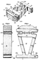
- FIGURE 1 is a perspective view of one preferred embodiment of the block in accordance with the invention.
- FIGURE 2 is a side plan view of the block of Fig. 1.
- FIGURE 3 is a top plan view of the block of Fig. 1.
- FIGURE 4 is a perspective view of an alternative preferred embodiment of the block in accordance with the invention.
- FIGURE 5 is a side plan view of the block of Fig. 4.
- FIGURE 6 is a top plan view of the block of Fig. 4.
- FIGURE 7 is a perspective view of a retaining structure constructed with one embodiment of the composite masonry block of the invention.
- FIGURE 8 is a cut away view of the wall shown in Fig. 7 showing a vertical wall taken along lines 8-8.
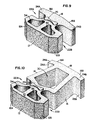
- FIGURE 9 is a perspective view of a further alternative embodiment of the block in accordance with the invention.
- FIGURE 10 is a perspective view of another further alternative embodiment of the block in accordance with the invention.
- FIGURE 11 is a top plan view of the block depicted in Fig. 10.
- FIGURE 12 is a cutaway view of a retaining structure constructed with the blocks depicted in Figs. 9 and 10.
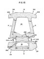
- FIGURE 13 is a top plan view of a block in accordance with a preferred alternative aspect of the invention.
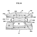
- FIGURE 14 is a top plan view of a block in accordance with a further preferred alternative aspect of the invention.
- FIGURE 15 is a side plan view of the block shown in Figure 13.
- FIGURE 16 is an enlarged side plan view of the block depicted in Figure 15 showing, in detail, aspects of protrusion 26.
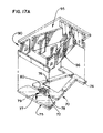
- FIGURE 17A is an exploded perspective view of the stripper shoe and head assembly of the invention.
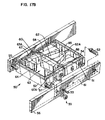
- FIGURE 17B is perspective view of the mold assembly of the invention.
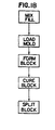
- FIGURE 18 is a schematic depiction of the molding process of the invention.
- the block generally comprises a front surface 12 and a back surface 18 adjoined by first and second side surfaces 14 and 16, respectively, as well as a top surface 10 and a bottom surface 8 each lying adjacent said front 12, back 18, and first 14 and second 16 side surfaces.
- Each of said side surfaces has an inset, 22A and 22B, spanning from the block top surface 10 to the block bottom surface 8.
- the block top surface 10 may also comprise one or more protrusions 26. Each protrusion is preferably positioned adjacent an inset 22A or 22B, on the block top surface 10.
- the block back surface 18 generally comprises first and second legs 24A and 24B, respectively.
- the first leg 24A extends from the back surface 18 beyond the plane of the block first side 14.
- the second leg 24B extends from the back surface 18 beyond the plane of the block second side 16.
- the composite masonry block of the invention generally comprises a block body.
- the block body 5 functions to retain earth without the use of secondary mechanisms such as pins, dead heads, webs and the like.
- the block body provides a retaining structure which may be manually positioned by laborers while also providing a high relative mass per square foot of face or front surface presented in the wall.
- the block may generally comprise a six-surface article.
- the most apparent surface of the block is generally the front surface 12 which functions to provide an ornamental or decorative look to the retaining structure, Figs. 1-3.
- the front surface of the block may be flat, rough, split, convex, concave, or radial. Any number of designs may be introduced into the front surface. Two preferred front surfaces may be seen in Figs. 1-3 and 4-6. Additionally, two alternative embodiments of the block of the invention may be seen in Figs. 9-11.
- the block of the invention may comprise a flat or planar front surface or a roughened front surface 12 created by splitting a portion of material from the front of the block, Fig. 1-3. In accordance with one other embodiment of the invention, the block may comprise a split or faceted front surface having three sides, Figs. 4-6.
- the block of the invention generally also comprises two side surfaces 14 and 16, Figs. 1-6. These side surfaces assist in definition of the block shape as well as in the stacked alignment of the block.
- the block of the invention may comprise side surfaces which take any number of forms including flat or planar side surfaces, angled side surfaces, or curved side surfaces.
- the side surfaces may also be notched, grooved, or otherwise patterned to accept any desired means for further aligning or securing the block during placement.
- Figs. 1-6 One preferred design for the side surfaces may be seen in Figs. 1-6. As can be seen, the side surfaces 14 and 16 are angled so as to define a block which has a greater width at the front surface 12 than at the back surface 18. Generally, the angle of the side surfaces (See Figs. 3 and 6) in relationship to the back surface as represented by alpha degrees, may range from about 70° to 90°, with an angle of about 75° to 85°, being preferred.
- the side surfaces may also comprise insets 22A and 22B for use in receiving other means which secure and align the blocks during placement.
- the insets may span from the block top surface 10 to the block bottom surface 8. Further, these insets may be angled across the height of the block to provide a structure which gradually sets back over the height of the wall. When mated with protrusions 26, the insets may also be angled to provide a retaining wall which is substantially vertical.
- the angle and size of the insets may be varied in accordance with the invention.
- the area of the inset adjacent the block bottom surface 8 should be approximately the same area as, or only slightly larger than, protrusion 26 with which it will mate.
- the area of the insets adjacent the block top surface 10 is preferably larger than the protrusion 26 by a factor of 5% or more and preferably about 1% to 2% or more. This will allow for adequate movement in the interfitting of blocks in any structure as well as allowing blocks of higher subsequent courses to setback slightly in the retaining structure. Further, by varying the size and position of the inset relative to protrusion 26, the set back of the wall may be varied.
- the set back of a retaining structure may be varied in the structure. For example, by pulling the blocks forward as far as possible a setback of about 3 mm (1/8") may be attained in the wall. By pushing the blocks backward as far as possible, a set back of up to 19 mm (3/4") may be attained.
- movement forward and backward is the movement of protrusion 26 within the confines of insets 22A and 22B.
- top 10 and bottom 8 surfaces of the block function similarly to the side surfaces of the block.
- the top 10 and bottom 8 surfaces of the block serve to define the structure of the block as well as assisting in the aligned positioning of the block in any given retaining structure.
- the top and bottom surfaces of the block are generally flat or planar surfaces.
- either the top or bottom surface comprises a protrusion 26.
- the protrusion functions in concert with the side wall insets 22A and 22B to secure the blocks in place when positioned in series or together on a retaining structure by aligning the protrusions 26 within the given insets.
- the protrusions may take any number of shapes, they preferably have a kidney or dogbone shape.
- the protrusion may comprise two circular or oblong sections which are joined across their middle by a narrower section of the same height. The central narrow portion in the protrusion 26 (Figs.
- the protrusions may comprise formed nodules or bars having a height ranging from about 10 mm (3/8 inch) to 19 mm (3/4 inch), and preferably about 13 mm (1/2 inch) to 15 mm (5/8 inch).
- the width or diameter of the protrusions may range from about 25 mm (1 inch) to 75 mm (3 inches), and preferably about 37 mm (1-1/2 inches) to 62 mm (2-1/2 inches).
- the protrusions In shipping, the protrusions may be protected by stacking the blocks in inverted fashion, thereby nesting the protrusions within opening 30.
- the protrusions 26 and insets 22A and 22B may be used with any number of other means which function to assist in securing the retaining wall against fill.
- Such devices include tie backs, deadheads, as well as web matrices such as GEOGRIDTM available from Mirafi Corp. or GEOMETTM available from Amoco.
- the back surface 18 of the block generally functions in defining the shape of the block, aligning the block as an element of any retaining structure, as well as retaining earth or fill. To this end, the back surface of the block may take any shape consistent with these functions.
- the back surface may preferably be planar and have surfaces 28A and 28B which extend beyond the side surfaces of the block.
- the block may be molded with any number of openings including central opening 30. This central opening 30 in the block allows for a reduction of weight during molding. Further, these openings allow for the block to be filled with earth or other product such as stone, gravel, rock, and the like which allows for an increase in the effective mass of the block per square foot of front surface. Openings may also be formed in the front portion of the blocks as can be seen by openings 34 and 36. Additional fill may be introduced into openings 30, 34, and 36 as well as the openings formed between surfaces 28A and 28B and adjacent side walls 14 and 16, respectively.
- a series of blocks are preferably placed adjacent each other, forming a series of fillable cavities.
- Each block preferably will have a central cavity 30 for filling as well as a second cavity formed between any two adjacently positioned blocks.
- This second cavity is formed by opposing side walls 14 and 16, and adjacently positioned back surfaces 28A and 28B.
- This second cavity formed in the retaining structure by the two adjacent blocks, holds fill and further increases the mass or actual density of any given block structure per square foot of front surface area.
- an unfilled block may weigh from about 559 to 752 kg/cm 2 (115 to 155 pounds), preferably from about 559 to 613 kg/m 2 (115 to 125 pounds per square foot) of front surface.
- the block mass will vary depending upon the fill used but preferably the block may retain a mass of about 785 to 882 (160 to 180 pounds), and preferably about 806 to 860 kg/m 2 (165 to 175 pounds per square foot) of front surface when using rock fill such as gravel or class 5 road base.
- FIG. 9 Two alternative preferred embodiments of the invention can be seen in Figs. 9-11.
- a block having cavities 34 and 36 for accepting fill.
- this block also has sidewall insets 22A and 22B and a protrusion for complimentary stacking with the blocks shown in Figs. 1-6 or Figs. 10-11. Consistent with the other embodiments of the block disclosed herein, this block allows for finishing walls having base courses of larger heavier blocks with blocks which are smaller, lighter and easier to stack on the higher or highest courses. While not required, the block depicted in Figs. 1-6 and 10-11 may be larger in dimension than the block of Fig.
- the blocks depicted in Fig. 9 may weigh from about 27 to 45 kg (60 to 100 pounds), preferably from about 34 to 43 kg (75 to 95 pounds), and most preferably from about 36 to 41 kg (80 to 90 pounds), with the filled block mass varying from about 41 to 59 kg (90 to 130 pounds), preferably from about 43 to 57 kg (95 to 125 pounds), and most preferably from about 48 to 52 kg (105 to 115 pounds) per 0,093 m 2 (square foot) of front surface using rock fill such as gravel or class 5 road base.
- FIGs. 10 and 11 Another alternative embodiment of the block of the invention can be seen in Figs. 10 and 11.
- the block depicted in Figs. 10 and 11 has angled first and second legs 24A and 24B, respectively, as well as an angled back wall sections, 18, 18A, and 18B.
- the resulting back surfaces 28A and 28B (Fig. 11), have a reduced angle alpha which increases the structural integrity of the wall by increasing the walls resistance to blow out.
- the angled back surfaces 28A and 28B provide a natural static force which resist the pressure exerted by the angle of repose of fill on any given retaining structure.
- the angled back surfaces 28A and 28B may be anchored in fill placed between adjacent blocks. Any force attempting to move this block forward, will have to also confront the resistance created by the forward angled back legs moving into adjacently positioned fill or, if the base course, the ground beneath the wall.
- angled back walls also facilitates manufacture of the blocks of the invention.
- the angled back sides 28A and 28B assist in allowing the conveying of blocks once they have been compressed and formed, and they are being transported to the curing facility.
- the proximity of the blocks on the conveyer may lead to physical contact. If this contact occurs at a high speed, the blocks may be physically damaged.
- the use of a conveyer which turns on curves in the course of transporting may naturally lead to contact between blocks and damage.
- Angling the back side legs 24A and 24B allows easier and more versatile conveyer transport and strengthens the back side legs.
- Angling the back sides of the block also assists in the formation of a cell when two blocks are placed adjacent to each other in the same plane.
- This cell may be used to contain any assortment of fill including gravel, sand, or even concrete.
- the design of the block of the invention allows the staggered or offset positioning of blocks when building a retaining wall structure.
- the internal opening 30 of the blocks depicted in Figs. 1-6 and 10-11 may be used in conjunction with the cells created by the adjacent blocks to create a network of channels for the deposition of fill.
- the opening 30 of a second course block may be placed over a cell created by two blocks positioned adjacent each other in the first course.
- opening 30 in second course block is aligned with a cell in the next lower course and this cell may be filled by introducing gravel, sand, etc. into the opening in the second course block.
- the addition of further courses allows the formation of a series of vertical channels across the retaining structure, (see Fig. 7).
- the back legs 24A and 24B may angle towards the front surface of the block ranging from about 5 degrees to 20 degrees, preferably about 7 degrees to 15 degrees, and most preferably about 10 degrees to twelve degrees.
- the angle beta may generally range from about 60 to 80 degrees, preferably about 60 to 75 degrees, and most preferably about 65 to 70 degrees. Further, this block (Figs.
- 10 and 11 may vary in weight from about 45 to 68 kg (100 to 150 pounds), preferably about 50 to 64 kg (110 to 140 pounds), and most preferably from about 52 to 57 kg (115 to 125 pounds), with the filled block mass varying from about 95 to 120 kg (210 to 265 pounds), preferably from about 100 to 116 kg (220 to 255 pounds), and most preferably from about 102 to 109 kg (225 to 240 pounds) per 0,093 m 2 (square foot) of front surface using rock fill such as gravel or class 5 road base.
- FIG. 13-16 A further preferred embodiment of the invention may be seen in Figures 13-16.
- structures such as those seen in Figures 7 and 8, as well as Figure 12, (for example a retaining wall)
- Figure 12 for example a retaining wall
- several concerns may arise depending upon the dimensions of the block, length and height of the structure, environmental conditions including the nature of the fill used behind the wall as well as the environment in which the wall is placed including landscape geography, weather, etc.
- certain concerns with the dimensions of the block as well as the various protrusions, openings, and associated block features may also be raised.
- the landscape structure such as that shown in Figure 8
- the structure is generally assembled one course at a time while the appropriate fill is placed behind the wall.
- the structural integrity of a composite masonry block structure generally comes from the coefficient of friction between the blocks of adjacent courses, the footprint of the blocks used in the structure, as well as the nature of the protrusion 26.
- the protrusion functions to secure the block on which it is placed or the blocks of the next adjacent course by interfitting with insets 22A and 22B.
- the composite masonry blocks in accordance with this aspect of the invention are generally similar to those shown in Figures 9-11.
- These blocks comprise openings 30 and 35 as well as a front face 12 which may be faceted (see Figure 13 at 12A and 12B), or unfaceted (see Figure 14).
- These blocks provide insets, 22A and 22B, as well as, a protrusion 26 which may span a portion of the upper surface 10 of the block and may boarder the insets 22A and 22B.
- the protrusion can have four sides. The angle on each of these four sides may vary in accordance with the invention to provide for a more secure placement of blocks as well as ease in processing.
- Side 26A represented by length A may generally be found adjacent opening 35.
- Protrusion side 26B spanning length B may generally be found adjacent opening 30.
- sides 26C generally span length C may be found adjacent insets 22A and 22B.
- protrusion 26 generally has visible three sidewalls, 26A and 26B which are adjoined by 26C, in this view.
- protrusion 26 sidewall 26B is a position towards the block back 18 and is angled so as to provide an adequate stopping or nesting mechanism to prevent any block, placed immediately adjacent it, from moving forward when stacked in an interlocking form, i.e. by interlocking the protrusion of one block with the insets of an immediately adjacent second block.
- protrusion surface 26A may be formed more easily during block molding. Reducing the angle of surface 26A from vertical allows the application and release of the heated stripper shoe in a manner which lowers the potential for retaining fill within the heated stripper shoe indentation, (see Figure 17A at 79).
- the positioning of protrusion surfaces 26A and 26B may depend upon how the block is to be used, with protrusion surface 26B positioned to resist the forward movement of subsequent courses of blocks and surface 26A positioned to facilitate manufacture of the block but not compromise the structural integrity of, for example, the resulting wall.
- the protrusion 26 preferably may also span the portion of the topside 10 of the block between inset 22A and 22B.
- protrusion walls 26C run a distance C as can be seen in Figures 13 and 14.
- protrusion 26 sidewalls 26C may comprise any angle in relationship to vertical which benefits ease of manufacture and the structural integrity of any structure made from the block of the invention.
- Extending the protrusion 26 across the top side 10 of a portion of the block also benefits manufacture.
- the mold will be filled with composite mix to the intended volume.
- the heated stripper shoe will then descend upon the fill, compressing the fill, and forming the block of the invention.
- the heated stripper shoe will form protrusion 26 through complementary patterning in indentation 79 in the underside of the heated stripper shoe (see Figure 17A) to form protrusion 26.
- Figure 16 shows an enlarged cross-sectional view of protrusion 26.
- protrusion surface 26B generally has an angle delta in relationship to vertical as shown by axis x-x'.
- angle delta generally ranges from about 0-10 degrees from vertical, preferably about 2-7 degrees from vertical, and most preferably about 5 degrees from vertical.
- protrusion surface 26A will generally have an angle theta which allows ease of manufacture which prevents fill from adhering from the underside of the heated stripper shoe.
- angle theta may range from 10 to 25 degrees from vertical, preferably from about 15 to 22 degrees from vertical, and preferably about 20 degrees from vertical as represented by access z-z', Figure 16.
- protrusion surfaces 26A and 26B may vary depending upon the structure of the block in the manner in which the block is used in, in overall landscape structure.
- surface 26B will preferably be used in order to retain blocks of adjacent courses in place and against forward movement resulting from the physical pressure created by fill loaded behind the structure.
- protrusion surface 26A will generally be positioned in a non-retaining area of the protrusion so as to facilitate ease and manufacture.
- protrusion surface 26C may range in angle from vertical to those limitations put forth for protrusion surface 26A. Generally, the angle of protrusion surface 26C should be adjusted to maintain the structural integrity of the block, provide the maximum resistive forces to blocks of adjacing courses, and provide ease in manufacturing.
- protrusion 26 may span from inset 22A to inset 22B across a portion of the top surface of the block.
- the protrusion will have a height ranging from 6 to 19 mm (one-quarter inch to three-quarter inches) and preferably from about 10 to 12 mm (three-eighth inches to one-half inches).
- the overall width of the protrusion from surface 26A to 26B will generally range from about 25 to 100 mm (1 inch to 4 inches), preferably about 50 to 75 mm (2 to 3 inches), and most preferably about 63 mm (2 1/2 inches) between protrusion surface 26A and 26B.
- these ranges may be changed or otherwise altered, but still within the scope of the invention.
- the composite masonry block 5 of the invention may be used to build any number of landscape structures. Examples of the structures which may be constructed with the block of the present invention are seen in Figs. 7-8. As can be seen in Fig. 7, the composite masonry block of the invention may be used to build a retaining wall 10 using individual courses or rows of blocks to construct a wall to any desired height.
- construction of a structure such as a retaining wall 10 may be undertaken by first defining a trench area beneath the plane of the ground in which to deposit the first course of blocks. Once defined, the trench is partially refilled and tamped or flattened. The first course of blocks is then laid into the trench. Successive courses of blocks are then stacked on top of preceding courses while backfilling the wall with soil.
- the blocks of the present invention also allow for the production of serpentine walls.
- the blocks may be placed at an angle in relationship to one another so as to provide a serpentine pattern having convex and concave surfaces.
- blocks of the invention may be positioned adjacent each other by reducing either surface 28A or 28B on one or both blocks. Such a reduction may be completed by striking leg 24A or 24B with a chisel adjacent deflection 19, see Figs. 1 and 4.
- Deflection 19 is preferably positioned on the block back surface 18 to allow reduction of the appropriate back surface leg (24A or 24B) while retaining enough potential open area for filling between blocks. Structures made from composite masonry blocks are disclosed in commonly assigned U.S. Patent No. 5,062,610 which is incorporated herein by reference.
- a supporting matrix may be used to anchor the blocks in the earth fill behind the wall.
- One advantage of the block of the invention is that despite the absence of pins, the distortion created by the block protrusions 26 when mated with insets 22A or 22B anchors the matrix when pressed between two adjacent blocks of different courses.
- the complementary design of the blocks of the invention allow the use of blocks 40 such as those depicted in Figs. 1-6 and 10-11 with blocks 42 which are shorter in length in the construction retaining wall structures, (Fig. 12). Tie-backs, deadheads, and web matrices may all be used to secure the retaining wall structure 46 in place.
- the generally large pound per square-foot front area of the blocks depicted herein allows blocks such as those depicted in Figs. 1-6 and 10-11 to be used in the base courses with blocks such as those depicted in Fig. 9 used in the upper courses.
- the design of all the blocks disclosed herein allows the use retaining means such as geometric matrices (i.e., webs), deadheads and tie backs without pins.
- retaining means such as geometric matrices (i.e., webs), deadheads and tie backs without pins.
- Such securing means may be useful in anchoring the smaller blocks in place when used, for example, towards the upper portion of the retaining structure.
- the invention also comprises a heated stripper shoe, a heated stripper shoe/mold assembly and a method of forming concrete masonry blocks with the shoe and mold assembly.
- the stripper shoe and mold assembly generally includes a stripper shoe plate 70, having a lower side 75 and an upper side 77, Fig. 17A.
- the stripper shoe plate 70 may have indentations to form block details such as those shown at 79 on the shoe lower side 75, (see also 26 at Figs. 1 and 4).
- Heat elements 78 may be positioned on the stripper shoe plate upper side 77.
- a heat shroud 80 Positioned over the heat elements 78 on the upper surface of the shoe plate is a heat shroud 80 (shown in outline).
- the heat shroud lower side is configured to cover the heat elements 78.
- the assembly may also comprise a standoff 90 which attaches the assembly to the block machine head 95.
- the standoff 90 is capable of spacing the stripper shoe plate 70 appropriately in the block machine and insulating the head from the heat developed at the surface of the stripper shoe plate 70.
- the assembly also comprises a mold 50 having an interior perimeter designed to complement the outer perimeter of the stripper shoe plate 70.
- the mold generally has an open center 63 bordered by the mold walls.
- a pallet Positioned beneath the mold is a pallet (not shown) used to contain the concrete fill in the mold and transport finished blocks from the molding machine.
- the stripper shoe 70 serves as a substrate on which the heat elements 78 are contained. Further, the stripper shoe plate 70 also functions to form the body of the block as well as detail in the blocks through indentations 79 in the stripper shoe lower surface 75. In use, the stripper shoe 70 functions to compress fill positioned in the mold and, once formed, push or strip the block from the mold 50.
- the stripper shoe plate 70 may take any number of designs or forms including ornamentation or structural features consistent with the block to be formed within the mold. Any number of steel alloys may be used in fabrication of the stripper shoe as long as these steel alloys have sufficient resilience and hardness to resist abrasives often used in concrete fill.
- the stripper shoe 70 is made from steel alloys which will resist continued compression and maintain machine tolerances while also transmitting heat from the heat elements through the plate 70 to the fill. In this manner, the total thermal effect of the heat elements is realized within the concrete mix.
- the stripper shoe plate 70 is made from a carbonized steel which may further be heat treated after forging.
- Preferred metals include steel alloys having a Rockwell "C"-Scale rating from about 60-65 which provide optimal wear resistance and the preferred rigidity.
- metals also found useful include high grade carbon steel of 41-40 AISI (high nickel content, prehardened steel), carbon steel 40-50 (having added nickel) and the like.
- a preferred material includes carbon steel having a structural ASTM of A36.
- Preferred steels also include A513 or A500 tubing, ASTM 42-40 (prehardened on a Rockwell C Scale to 20 thousandths of an inch).
- the stripper shoe plate 70 may be formed and attached to the head assembly by any number of processes known to those of skill in the art including the nut, washer, and bolt mechanisms known to those of skill in the art.
- the stripper shoe comprises a first section 72 and a second section 74, with the first section 74 having indentations 79 on the shoe lower side 75.
- a heat element 78 is positioned over indentation 79.
- the outer perimeter of the stripper shoe 70 may generally complement the interior outline of the mold 50.
- Heat elements 78 are preferably positioned adjacent to indentation 79 on the shoe lower side 75 to facilitate the formation of that point of detail created by the indentations 79 in the stripper shoe 70. While generally shown with one form of indentation 79, the stripper shoe plate 70 may be capable of forming any number of designs through indentations in the shoe plate lower surface 75 depending on the nature of the block to be formed.
- the invention may also comprise one or more heat elements 78.
- the heat element 78 functions to generate and transmit radiant energy to the upper surface 77 of the stripper shoe 70.
- the heat elements are preferably positioned adjacent indentation 79 in the shoe plate lower surface 75.
- any type and quantity of heat elements 78 may be used in accordance with the invention.
- preferred heat elements have been found to be those which will withstand the heavy vibration, dirt and dust common in this environment.
- Preferred heat elements are those which are easily introduced and removed from the system. This allows for easy servicing of the stripper shoe assembly without concerns for injury to the operator through thermal exposure or complete disassembly of mold 50, stripper shoe 70, shroud 80, and standoff 90.
- the heat element may comprise any number of electrical resistance elements which may be, for example, hard wired, solid state, or semiconductor circuitry, among others.
- the heat element 78 may generally be positioned over indentations 79 in the stripper shoe lower surface 75, Fig. 17A. By this positioning, the heat element 78 is able to apply heat to the stripper shoe 70 in the area where it is most needed, that is, where the block detail (in this case, protrusion 26, see Fig. 1) is formed in the concrete mix held by the mold.
- the heat element 78 may comprise any number of commercially available elements. Generally, the power provided by the heat element may range anywhere from 300 watts up to that required by the given application. Preferably, the power requirements of the heat element may range from about 400 watts to 1500 watts, more preferably 450 watts to 750 watts, and most preferably about 600 watts. Power may be provided to the heat elements by any number of power sources including for example, 110 volt sources equipped with 20 to 25 amp circuit breakers which allow the assembly to run off of normal residential current. If available, the assembly may also run off of power sources such as 3-phase, 220 volt sources equipped with 50 amp circuit breakers or other power sources known to those of skill in the art. However, the otherwise low power requirements of the assembly allow use in any environment with minimal power supplies.
- Elements found useful in the invention include cartridge heaters, available from Vulcan Electric Company, through distributor such as Granger Industrial Co. of Minnesota. These elements have all been found to provide easy assembly and disassembly in the stripper shoe of the invention as well as good tolerance to vibration, dirt, dust, and other stresses encountered in such an environment.
- the heat elements may be activated by hard wiring as well as any other variety of electrical feeds known to those of skill in the art. If hard wiring is used, provision may be made to circulate this wiring through the shroud 80 and standoff 90 by various openings 88.
- the heat element 78 may be externally controlled through any number of digital or analogue mechanisms known to those of skill in the art located at an external point on the block machine.
- Heating the stripper shoe elements 78 allows the formation of block detail such as indentations or protrusions, or combinations thereof without the fouling of the shoe plate 70. Detail is essentially formed by case hardening the concrete fill adjacent the element 78. This allows the formation of block detail which is both ornate and has a high degree of structural integrity.
- the invention may also comprise means of attaching the heat element 78 to the stripper shoe 70 such as a heat block.
- attachment means for the heat elements 76 may be seen in commonly assigned, not prepublished U.S. Patent Application No. 07/828,031, filed January 30, 1992.
- the stripper shoe may also comprise a heat shroud 80 (shown in outline), Fig. 17A, which thermally shields or insulates the heat elements 78 and molding machine.
- the heat shroud 80 also functions to focus the heat generated by the heat elements 78 back onto the stripper shoe 70.
- the heat shroud 80 may take any number of shapes of varying size in accordance with the invention.
- the heat shroud 80 should preferably contain the heat elements 78.
- the heat shroud 80 preferably has a void formed within its volume so that it may be placed over the heat elements 78 positioned on the upper surface 77 of the stripper shoe 70.
- the shroud 80 is preferably positioned flush with the stripper shoe upper surface 77.
- the heat shroud 80 there is a space between the upper surface of the heat element and the opening or void in the heat shroud 80. Air in this additional space also serves to insulate the standoff and mold machine from the heat created by the heat element 78.
- the heat shroud 80 may comprise any metal alloy insulative to heat or which is a poor conductor of thermal energy.
- Metal alloys such as brass, copper, or composites thereof are all useful in forming the heat shroud 80.
- aluminum and its oxides and alloys are also useful. Alloys and oxides of aluminum are preferred in the formation of the heat shroud 80 due to the ready commercial availability of these compounds.
- Aluminum alloys having an ASTM rating of 6061-T6 and 6063-T52 are generally preferred over elemental aluminum.
- the assembly may additionally comprise a head standoff 90, attached to the stripper shoe plate 70, to position, aid in compression, and attach the head assembly to the block machine.
- a head standoff 90 attached to the stripper shoe plate 70, to position, aid in compression, and attach the head assembly to the block machine.
- the head standoff 90 may comprise any number of designs to assist and serve this purpose.
- the head standoff may also be used to contain and store various wiring or other elements of the stripper shoe assembly which are not easily housed either on the stripper shoe 70, or the heat shroud 80.
- the head standoff 90 may comprise any number of metal alloys which will withstand the environmental stresses of block molded processes.
- Preferred metals include steel alloys having a Rockwell "C"-Scale rating from about 60-65 which provide optimal wear resistance and the preferred rigidity.
- metals found useful in the manufacture of the head standoff mold of the present invention include high grade carbon steel of 41-40 AISI (high nickel content, prehardened steel), carbon steel 40-50 (having added nickel) and the like.
- a preferred material includes carbon steel having a structural ASTM of A36.
- the head standoff 50 may be made through any number of mechanisms known to those of skill in the art.
- the assembly may also comprise a mold 50.
- the mold generally functions to facilitate the formation of the blocks.
- the mold may comprise any material which will withstand the pressure to be applied to the block filled by the head.
- metal such as steel alloys having a Rockwell "C"-Scale rating from about 60-65 which provide optimal wear resistance and the preferred rigidity.
- metals found useful in the manufacture of the mold of the present invention include high grade carbon steel of 41-40 AISI (high nickel content, prehardened steel), carbon steel 40-50 (having added nickel) and the like.
- a preferred material includes carbon steel having a structural ASTM of A36.
- Mold 50 useful in the invention may take any number of shapes depending on the shape of the block to be formed and be made by any number of means known to those of skill in the art.
- the mold is produced by cutting the steel stock, patterning the cut steel, providing an initial weld to the pattern mold pieces and heat treating the mold.
- Heat treating generally may take place at temperatures ranging from about 524 to 746°C (1000°F to about 1400°F) from 4 to 10 hours depending on the ability of the steel to withstand processing and not distort or warp. After heat treating, final welds are then applied to the pieces of the mold.
- the mold walls generally function according to their form by withstanding the pressure created by the block machine. Further, the walls measure the height and the depth of resulting blocks.
- the mold walls must be made of a thickness which will accommodate the processing parameters of the block formation given a specific mold composition.
- the mold comprises a front surface 52, back surface 54, as well as a first side surface 51, and a second side surface 58.
- each of these surfaces function to hold fill within a contained area during compression, thus resulting in the formation of a block. Accordingly, each of these mold surfaces may take a shape consistent with this function.
- the mold side walls, 51 and 58 may also take any shape in accordance with the function of the mold.
- the side walls each comprise an extension 64 which are useful in forming the insets 22A and 22B in the block of the invention, see Fig. 1.
- extension 64 may have a dimension which is fairly regular over the depth of the mold.
- insets 22A and 22B are required which have a conical shape as seen in Figs. 2 and 5, the extensions may be formed to have a width at the top of the mold which is greater than the width of the extension at the bottom of the mold. This will result in the insets 22A and 22B which are seen in the various embodiments of the block of the invention shown in Figs. 1-6 as well as Figs. 9-11 while also allowing stripping of the block from the mold 50 during processing.
- the mold may preferably also comprise one or more support bars 60 and core forms 62.
- the support bars 60 hold the core forms 62 in place within the mold cavity 63.
- the support bars may take any shape, size, or material composition which provides for these functions.
- support bar 60 is preferably long enough to span the width of the mold 50 resting on opposing side walls 51 and 59.
- the support bar 60 functions to hold the core 62 within the mold central opening 63. Complementing this function, the support bar 60 is generally positioned in the central area 63A of the opposing side walls 51 and 58.
- the core form 62 may also be held in place by an additional support 62A (shown in outline) placed between the back wall 54 of the mold 50 and the core form 62.
- Support bar 60 may also be held in place by a bracket 85 affixed above and around the outer perimeter of the mold 50 at the edges of walls 51, 52, 58, and 54. The use of these various support structures reduces core form vibration during the molding process.
- the core form 62 are supported by bar 60 which span the width of the mold 50 resting on the opposing side walls 51 and 58.
- the core forms have any number of functions.
- the core forms 62 act to form voids in the resulting composite masonry block.
- the core forms lighten the blocks, reduce the amount of fill necessary to make a block, and add to the portability and handleability of the blocks to assist in transport and placement of the blocks.
- the core form 62 is affixed to the support bar 60 at insert regions 60A. These insert regions 60A assist in positioning the core forms.
- the support bar 60 projects upwards from mold 50.
- the stripper shoe 70 and stand off 80 may be partitioned or split as can be seen by openings 76 and 96, respectively (Fig. 17A). The separate sections of the shoe 70 and stand off will allow adequate compression of the fill without obstruction by the support bar 60. In turn, the various sections of the stripper shoe 70 and stand off 90 may be held in place by the head 95.
- the mold of the invention may be assembled through any number of means, one manner is that shown in Fig. 17B.
- the mold is held in place by two outer beams 55 and 56, each of which have an interior indentation, 61 and 67 respectively.
- bolt elements 57 may be fit into the front wall 52 and back wall 54 of the mold 50.
- the side walls 51 and 58 of the mold may be held in the outer beams of the mold by nut plates 65 sized to fit in indentations 61 and 67.
- the nut plates 65 may be held within the outer beam indentations 61 by bolt means 53.
- the mold 50 may be held in place even though constructed of a number of pieces.
- An additional aspect of the present invention is the process for casting or forming the composite masonry blocks of this invention using a masonry block mold assembly, Figs. 17A and 17B.
- the process for making this invention includes block molding the composite masonry block by filling a block mold with mix and casting the block by compressing the mix in the mold through the application of pressure to the exposed mix at the open upper end of the block mold. An outline of the process can be seen in the flow chart shown in Fig. 18.
- the assembly is generally positioned in the block molding machine atop of a removable or slidable pallet (not shown).
- the mold 50 is then loaded with block mix or fill.
- the mold 50 is set to form one block. Once formed and cured, these blocks may be split along the deflections created by flanges 66 which may be positioned on the interior of sidewalls of the mold.
- the upper surface of the mold Prior to compression, the upper surface of the mold is vibrated to settle the fill and scraped or raked with the feed box drawer (not shown) to remove any excess fill.
- the mold is then subjected to compression directly by the stripper shoe 70 through head assembly.
- the stripper shoe 70 forces block fill towards either end of the mold and into the stripper shoe indentation 79 to create a protrusion 26 in the formed block, see Fig. 1.
- This indentation may range in size for example from about 25 to 75 mm (1 to 3 inches), preferably about 37 to 63 mm (1-1/2 to 2-1/2 inches), and most preferably about 44 to 50 mm (1-3/4 to 2 inches).
- this indentation 79 is heated by elements 78 so that protrusions 26 of minimal size and varying shape may be formed without the build up of fill on the stripper shoe 70 at indentation 79.
- the assembly may be used in the automatic manufacture of blocks by machine.
- Blocks may be designed around any number of different physical properties in accordance with ASTM Standards depending upon the ultimate application for the block.
- the fill may comprise from 75 to 95% aggregate being sand and gravel in varying ratios depending upon the physical characteristics which the finished block is intended to exhibit.
- the fill generally also comprises some type of cement at a concentration ranging from 4% to 10%.
- Other constituents may then be added to the fill at various trace levels in order to provide blocks having the intended physical characteristics.
- the fill constituents may be mixed by combining the aggregate, the sand and rock in the mixer followed by the cement. After one to two and one-half minutes, any plasticizers that will be used are added. Water is then introduced into the fill in pulses over a one to two minute period. The concentration of water in the mix may be monitored electrically by noting the electrical resistance of the mix at various times during the process. While the amount of water may vary from one fill formulation to another fill formulation, it generally ranges from about 1% to about 6%.
- a compression mechanism such as a head carrying the inventive assembly converges on the exposed surface of the fill.
- the stripper shoe assembly 30 acts to compress the fill within the mold for a period of time sufficient to form a solid contiguous product.
- the compression time may be anywhere from 0.5 to 4 seconds and more preferably about 1.5 to 2 seconds.
- the compression pressure applied to the head ranges from about 6,9 to 55 MN/m 2 (1000 to about 8000 psi) and preferably is about 27,6 MN/m 2 (4000 psi).
- the stripper shoe 70 in combination with the underlying pallet acts to strip the blocks from the mold 50. At this point in time the blocks are formed.
- Any block machine known to those of skill in the art may be used in accordance with the invention.
- One machine which has been found useful in the formation of blocks is a Besser V-3/12 block machine.
- the mold may be vibrated.
- the fill is transported from the mixer to a hopper which then fills the mold 50.
- the mold is then agitated for up to 2 to 3 seconds, the time necessary to ensure the fill has uniformly spread throughout the mold.
- the blocks are then formed by compressive action by the compressive action the head. Additionally, this vibrating may occur in concert with the compressive action of the head onto the fill in the mold. At this time, the mold will be vibrated for the time in which the head is compressed onto the fill.
- the blocks may be cured through any means known to those with skill in the art. Curing mechanisms such as simple air curing, autoclaving, steam curing or mist curing, are all useful methods of curing the block of the present invention.
- Air curing simply entails placing the blocks in an environment where they will be cured by open air over time.
- Autoclaving entails placing the blocks in a pressurized chamber at an elevated temperature for a certain period of time. The pressure in the chamber is then increased by creating a steady mist in the chamber. After curing is complete, the pressure is released from the chamber which in turns draws the moisture from the blocks.
- the blocks may be split to create any number of functional or aesthetic features in the blocks.
- Splitting means which may be used in the invention include manual chisel and hammer as well as machines known to those with skill in the art.
- Flanges 66 (Fig. 9) may be positioned on the interior of the mold 50 side walls to provide a natural weak point or fault which facilitates the splitting action.
- the blocks may be split in a manner which provides a front surface 12 which is smooth or coarse (Figs. 1-6 and Figs. 9-11), single faceted (Fig. 1) or multifaceted (Fig. 4), as well as planar or curved.
- the blocks may be split to provide a faceted front surface as shown in Figs. 4-6 by surfaces 12A, 12, and 12B.
- splitting will be completed by an automatic hydraulic splitter.
- the blocks may be cubed and stored.
Abstract
Description
- The invention generally relates to concrete masonry blocks. More specifically, the invention relates to concrete masonry blocks which are useful in forming various retaining structures.
- Soil retention, protection of natural and artificial structures, and increased land use are only a few reasons which motivate the use of landscape structures. For example, soil is often preserved on a hillside by maintaining the foliage across that plain. Root systems from the trees, shrubs, grass, and other naturally occurring plant life, work to hold the soil in place against the forces of wind and water. However, when reliance on natural mechanisms is not possible or practical, man often resorts to the use of artificial mechanisms such as retaining walls.
- In constructing retaining walls, many different materials may be used depending on the given application. If a retaining wall is intended to be used to support the construction of a roadway, a steel wall or a concrete and steel wall may be appropriate. However, if the retaining wall is intended to landscape and conserve soil around a residential or commercial structure, a material may be used which compliments the architectural style of the structure such as wood timbers or concrete block.
- Of all these materials, concrete block has received wide and popular acceptance for use in the construction of retaining walls and the like. Blocks used for these purposes include those disclosed by Forsberg, U.S. Patent Nos. 4,802,320 and Design 296,007, among others.
- Previously, blocks have been designed to "setback" at an angle to counter the pressure of the soil behind the wall. Setback is generally considered the distance in which one course of a wall extends beyond the front surface of the next highest course of the same wall. Given blocks of the same proportion, setback may also be regarded as the distance which the back surface of a higher course of blocks extends backwards in relation to the back surface of a lower course of the wall.
- There is often a need in the development of structures such as roadways, abutments and bridges to provide maximum usable land and a clear definition of property lines. Such definition is often not possible through use of a composite masonry block which results in a setback wall. For example, a wall which sets back by its very nature will cross a property line and may also preclude maximization of usable land in the upper or subjacent property. As a result, a substantially vertical wall is more appropriate and desirable.
- However, in such instances, vertical walls may be generally held in place through the use of well known mechanisms such as pins, deadheads, tie backs or other anchoring mechanisms to maintain the vertical profile of the wall. Besides being complex, anchoring mechanisms such as pin systems often rely on only one strand or section of support tether which, if broken, may completely compromise the structural integrity of the wall. Reliance on such complex fixtures often discourages the use of retaining wall systems by the everyday homeowner. Commercial landscapers may also avoid complex retaining wall systems as the time and expense involved in constructing these systems is not supportable given the price at which landscaping services are sold.
- Further, retaining structures are often considered desirable in areas which require vertical wall but are not susceptible to any number of anchoring matrices or mechanisms. For example, in the construction of a retaining wall adjacent a building or other structure, it may not be possible to provide anchoring mechanisms such as a matrix web, deadheads or tie backs far enough into the retained earth to actually support the wall. Without a retaining mechanism such as a matrix web, tie-back, or dead head, many blocks may not offer the high mass per face square foot necessary for use in retaining structures which have a substantially vertical profile.
- Manufacturing processes may also present impediments to structures of adequate integrity and strength. Providing blocks which do not require elaborate pin systems or other secondary retaining and aligning means and are still suitable for constructing structures of optimal strength is often difficult. Two examples of block molding systems are disclosed in commonly assigned Woolford et al, US Patent No. 5062610 and Woolford, US Patent Application Serial No. 07/828031 filed January 30, 1992 which are incorporated herein by reference. In both systems, advanced design and engineering is used to provide blocks of optimal strength and, in turn, structures of optimal strength, without the requirement of other secondary systems such as pins and the like. The Woolford et al patent discloses a mold which, through varying fill capacities provides for the uniform application of pressure across the fill. The Woolford application discloses a means of forming block features through the application of heat to various portions of the fill.
- US 5044834 discloses a masonry block provided with a front surface, back surface, top surface and bottom surface, together with first and second sides each of which provide an inset. Through bores provided in the body of the block are used to accommodate Z-shaped pins which cooperate with similar bores in blocks in adjoining courses. The bore positions and the linking pins are rigidly connected to one another in use.
- As can be seen there is a need fr a composite masonry block which is stackable to form walls of high structural integrity without the use of complex pin and connection systems and without the need for securing mechanisms such as pins, or tie backs.
- In accordance with a first aspect of the invention, there is provided a pinless composite masonry block having a high unit mass per front surface square foot. The block comprises a front surface, a back surface, a top surface and a bottom surface and first and second sides, said first side having a first inset wherein said first inset extends from said block top surface to said block bottom surface, said second side having a second inset wherein said second inset extends from said block top surface to said block bottom surface, said block comprising one or more protrusions on said block top and / or said block bottom surface, wherein the one or more protrusions are configured to have a portion which will interlock with the said first or second inset of a block positioned in an adjacent course, said inset(s), having a greater relative size than said interlocking portion of said protrusion to permit relative rotation of the interlocking portion of said protrusion and the inset with which it is interlocked through a range of angles, whereby serpentine walls may be contructed from a plurality of such interlocking blocks.
- In use, the block may be made to form vertical or set back walls without pins or other securing mechanisms as a result of the high mass per front surface square foot.
- In accordance with an additional aspect of the invention there is provided structures resulting from the blocks of the invention.
- In accordance with a further aspect of the invention there is provided a mold and method of use resulting in the block of the invention.
- FIGURE 1 is a perspective view of one preferred embodiment of the block in accordance with the invention.
- FIGURE 2 is a side plan view of the block of Fig. 1.
- FIGURE 3 is a top plan view of the block of Fig. 1.
- FIGURE 4 is a perspective view of an alternative preferred embodiment of the block in accordance with the invention.
- FIGURE 5 is a side plan view of the block of Fig. 4.
- FIGURE 6 is a top plan view of the block of Fig. 4.
- FIGURE 7 is a perspective view of a retaining structure constructed with one embodiment of the composite masonry block of the invention.
- FIGURE 8 is a cut away view of the wall shown in Fig. 7 showing a vertical wall taken along lines 8-8.
- FIGURE 9 is a perspective view of a further alternative embodiment of the block in accordance with the invention.
- FIGURE 10 is a perspective view of another further alternative embodiment of the block in accordance with the invention.
- FIGURE 11 is a top plan view of the block depicted in Fig. 10.
- FIGURE 12 is a cutaway view of a retaining structure constructed with the blocks depicted in Figs. 9 and 10.
- FIGURE 13 is a top plan view of a block in accordance with a preferred alternative aspect of the invention.
- FIGURE 14 is a top plan view of a block in accordance with a further preferred alternative aspect of the invention.
- FIGURE 15 is a side plan view of the block shown in Figure 13.
- FIGURE 16 is an enlarged side plan view of the block depicted in Figure 15 showing, in detail, aspects of
protrusion 26. - FIGURE 17A is an exploded perspective view of the stripper shoe and head assembly of the invention.
- FIGURE 17B is perspective view of the mold assembly of the invention.
- FIGURE 18 is a schematic depiction of the molding process of the invention.
- Turning to the figures wherein like parts are designated with like numerals throughout several views, there is shown a composite masonry block in Figure 1. The block generally comprises a
front surface 12 and aback surface 18 adjoined by first and second side surfaces 14 and 16, respectively, as well as atop surface 10 and abottom surface 8 each lying adjacent saidfront 12, back 18, and first 14 and second 16 side surfaces. Each of said side surfaces has an inset, 22A and 22B, spanning from the blocktop surface 10 to theblock bottom surface 8. The blocktop surface 10 may also comprise one ormore protrusions 26. Each protrusion is preferably positioned adjacent aninset top surface 10. - The block back
surface 18 generally comprises first andsecond legs first leg 24A extends from theback surface 18 beyond the plane of the blockfirst side 14. Thesecond leg 24B extends from theback surface 18 beyond the plane of the blocksecond side 16. - The composite masonry block of the invention generally comprises a block body. The
block body 5 functions to retain earth without the use of secondary mechanisms such as pins, dead heads, webs and the like. Preferably, the block body provides a retaining structure which may be manually positioned by laborers while also providing a high relative mass per square foot of face or front surface presented in the wall. To this end, the block may generally comprise a six-surface article. - The most apparent surface of the block is generally the
front surface 12 which functions to provide an ornamental or decorative look to the retaining structure, Figs. 1-3. The front surface of the block may be flat, rough, split, convex, concave, or radial. Any number of designs may be introduced into the front surface. Two preferred front surfaces may be seen in Figs. 1-3 and 4-6. Additionally, two alternative embodiments of the block of the invention may be seen in Figs. 9-11. The block of the invention may comprise a flat or planar front surface or a roughenedfront surface 12 created by splitting a portion of material from the front of the block, Fig. 1-3. In accordance with one other embodiment of the invention, the block may comprise a split or faceted front surface having three sides, Figs. 4-6. - The block of the invention generally also comprises two
side surfaces - One preferred design for the side surfaces may be seen in Figs. 1-6. As can be seen, the side surfaces 14 and 16 are angled so as to define a block which has a greater width at the
front surface 12 than at theback surface 18. Generally, the angle of the side surfaces (See Figs. 3 and 6) in relationship to the back surface as represented by alpha degrees, may range from about 70° to 90°, with an angle of about 75° to 85°, being preferred. - The side surfaces may also comprise
insets top surface 10 to theblock bottom surface 8. Further, these insets may be angled across the height of the block to provide a structure which gradually sets back over the height of the wall. When mated withprotrusions 26, the insets may also be angled to provide a retaining wall which is substantially vertical. - The angle and size of the insets may be varied in accordance with the invention. However, the area of the inset adjacent the
block bottom surface 8 should be approximately the same area as, or only slightly larger than,protrusion 26 with which it will mate. The area of the insets adjacent the blocktop surface 10 is preferably larger than theprotrusion 26 by a factor of 5% or more and preferably about 1% to 2% or more. This will allow for adequate movement in the interfitting of blocks in any structure as well as allowing blocks of higher subsequent courses to setback slightly in the retaining structure. Further, by varying the size and position of the inset relative toprotrusion 26, the set back of the wall may be varied. Further, by varying the position of the protrusion within an inset of greater relative size the set back of a retaining structure may be varied in the structure. For example, by pulling the blocks forward as far as possible a setback of about 3 mm (1/8") may be attained in the wall. By pushing the blocks backward as far as possible, a set back of up to 19 mm (3/4") may be attained. Here again, movement forward and backward is the movement ofprotrusion 26 within the confines ofinsets - Generally, the top 10 and bottom 8 surfaces of the block function similarly to the side surfaces of the block. The top 10 and bottom 8 surfaces of the block serve to define the structure of the block as well as assisting in the aligned positioning of the block in any given retaining structure. To this end, the top and bottom surfaces of the block are generally flat or planar surfaces.
- Preferably, as can be seen in Figs. 1-6, either the top or bottom surface comprises a
protrusion 26. The protrusion functions in concert with theside wall insets protrusions 26 within the given insets. While the protrusions may take any number of shapes, they preferably have a kidney or dogbone shape. As can be seen in Figs. 1-6 as well as Figs. 9-11, the protrusion may comprise two circular or oblong sections which are joined across their middle by a narrower section of the same height. The central narrow portion in the protrusion 26 (Figs. 1-6) allows for orientation of the blocks to provide inner curving and outer curving walls by the aligned seating and the relative rotation of theprotrusion 26 within, and in relationship to, anyblock inset - Generally, the protrusions may comprise formed nodules or bars having a height ranging from about 10 mm (3/8 inch) to 19 mm (3/4 inch), and preferably about 13 mm (1/2 inch) to 15 mm (5/8 inch). The width or diameter of the protrusions may range from about 25 mm (1 inch) to 75 mm (3 inches), and preferably about 37 mm (1-1/2 inches) to 62 mm (2-1/2 inches). In shipping, the protrusions may be protected by stacking the blocks in inverted fashion, thereby nesting the protrusions within
opening 30. - Generally, the
protrusions 26 andinsets - The
back surface 18 of the block generally functions in defining the shape of the block, aligning the block as an element of any retaining structure, as well as retaining earth or fill. To this end, the back surface of the block may take any shape consistent with these functions. - One preferred embodiment of the block back surface can be seen in Figs. 1-6. In accordance with the invention, the back surface may preferably be planar and have
surfaces central opening 30. Thiscentral opening 30 in the block allows for a reduction of weight during molding. Further, these openings allow for the block to be filled with earth or other product such as stone, gravel, rock, and the like which allows for an increase in the effective mass of the block per square foot of front surface. Openings may also be formed in the front portion of the blocks as can be seen byopenings openings surfaces adjacent side walls - In use, a series of blocks are preferably placed adjacent each other, forming a series of fillable cavities. Each block preferably will have a
central cavity 30 for filling as well as a second cavity formed between any two adjacently positioned blocks. This second cavity is formed by opposingside walls - Generally, an unfilled block may weigh from about 559 to 752 kg/cm2 (115 to 155 pounds), preferably from about 559 to 613 kg/m2 (115 to 125 pounds per square foot) of front surface. Once filled, the block mass will vary depending upon the fill used but preferably the block may retain a mass of about 785 to 882 (160 to 180 pounds), and preferably about 806 to 860 kg/m2 (165 to 175 pounds per square foot) of front surface when using rock fill such as gravel or
class 5 road base. - Two alternative preferred embodiments of the invention can be seen in Figs. 9-11. First, as can be seen in Fig. 9, there is depicted a
block having cavities sidewall insets protrusion 26 allows for retention of these blocks in an interlocking fashion with the blocks of lower courses to form a wall of high structural integrity, (see Fig. 12). - The blocks depicted in Fig. 9 may weigh from about 27 to 45 kg (60 to 100 pounds), preferably from about 34 to 43 kg (75 to 95 pounds), and most preferably from about 36 to 41 kg (80 to 90 pounds), with the filled block mass varying from about 41 to 59 kg (90 to 130 pounds), preferably from about 43 to 57 kg (95 to 125 pounds), and most preferably from about 48 to 52 kg (105 to 115 pounds) per 0,093 m2 (square foot) of front surface using rock fill such as gravel or
class 5 road base. - Another alternative embodiment of the block of the invention can be seen in Figs. 10 and 11. As can be seen, the block depicted in Figs. 10 and 11 has angled first and
second legs - The resulting back surfaces 28A and 28B, (Fig. 11), have a reduced angle alpha which increases the structural integrity of the wall by increasing the walls resistance to blow out. The angled back surfaces 28A and 28B provide a natural static force which resist the pressure exerted by the angle of repose of fill on any given retaining structure. The angled back surfaces 28A and 28B may be anchored in fill placed between adjacent blocks. Any force attempting to move this block forward, will have to also confront the resistance created by the forward angled back legs moving into adjacently positioned fill or, if the base course, the ground beneath the wall.
- The use of angled back walls also facilitates manufacture of the blocks of the invention. Specifically, the angled back
sides back side legs - Angling the back sides of the block also assists in the formation of a cell when two blocks are placed adjacent to each other in the same plane. This cell may be used to contain any assortment of fill including gravel, sand, or even concrete. The design of the block of the invention allows the staggered or offset positioning of blocks when building a retaining wall structure. The
internal opening 30 of the blocks depicted in Figs. 1-6 and 10-11 may be used in conjunction with the cells created by the adjacent blocks to create a network of channels for the deposition of fill. Specifically, with the offset placement blocks from one course to the next, theopening 30 of a second course block may be placed over a cell created by two blocks positioned adjacent each other in the first course. Thus, opening 30 in second course block is aligned with a cell in the next lower course and this cell may be filled by introducing gravel, sand, etc. into the opening in the second course block. The addition of further courses allows the formation of a series of vertical channels across the retaining structure, (see Fig. 7). - From the axis created by
back wall 18 theback legs class 5 road base. - A further preferred embodiment of the invention may be seen in Figures 13-16. We have discovered that when constructing structures such as those seen in Figures 7 and 8, as well as Figure 12, (for example a retaining wall), several concerns may arise depending upon the dimensions of the block, length and height of the structure, environmental conditions including the nature of the fill used behind the wall as well as the environment in which the wall is placed including landscape geography, weather, etc. Additionally, depending upon the block manufacturing process used, certain concerns with the dimensions of the block as well as the various protrusions, openings, and associated block features, may also be raised. Specifically, when constructing the landscape structure such as that shown in Figure 8, the structure is generally assembled one course at a time while the appropriate fill is placed behind the wall. Once complete, the pressure on the wall will tend to force blocks of each subsequently higher course outward towards the front of the wall. The interlocking nature of the
protrusion 26 and insets, 22A and 22B, will generally resist the movement between the blocks of any two given courses. - We have found that the structural integrity of a composite masonry block structure generally comes from the coefficient of friction between the blocks of adjacent courses, the footprint of the blocks used in the structure, as well as the nature of the
protrusion 26. Generally, the protrusion functions to secure the block on which it is placed or the blocks of the next adjacent course by interfitting withinsets - As can be seen in Figures 13 and 14, the composite masonry blocks in accordance with this aspect of the invention are generally similar to those shown in Figures 9-11. These blocks comprise
openings front face 12 which may be faceted (see Figure 13 at 12A and 12B), or unfaceted (see Figure 14). These blocks provide insets, 22A and 22B, as well as, aprotrusion 26 which may span a portion of theupper surface 10 of the block and may boarder theinsets - Generally, as can be seen in Figures 13 and 14, the protrusion can have four sides. The angle on each of these four sides may vary in accordance with the invention to provide for a more secure placement of blocks as well as ease in processing.
Side 26A represented by length A may generally be foundadjacent opening 35.Protrusion side 26B spanning length B may generally be foundadjacent opening 30. In turn, sides 26C generally span length C may be foundadjacent insets - With the understanding that the block of the invention may be used in any number of structural configurations, an additional view of the protrusion of the invention may be seen in Figure 15 in accordance with a preferred aspect of the invention. As can be seen,
protrusion 26 generally has visible three sidewalls, 26A and 26B which are adjoined by 26C, in this view. In this instance,protrusion 26sidewall 26B is a position towards the block back 18 and is angled so as to provide an adequate stopping or nesting mechanism to prevent any block, placed immediately adjacent it, from moving forward when stacked in an interlocking form, i.e. by interlocking the protrusion of one block with the insets of an immediately adjacent second block. - Further, by changing the incline of
protrusion surface 26A so as to lessen the angle between theupper surface 10 of the block andprotrusion surface 26A (or away from vertical), the protrusion may be formed more easily during block molding. Reducing the angle ofsurface 26A from vertical allows the application and release of the heated stripper shoe in a manner which lowers the potential for retaining fill within the heated stripper shoe indentation, (see Figure 17A at 79). Here again, the positioning ofprotrusion surfaces protrusion surface 26B positioned to resist the forward movement of subsequent courses of blocks andsurface 26A positioned to facilitate manufacture of the block but not compromise the structural integrity of, for example, the resulting wall. - The
protrusion 26 preferably may also span the portion of thetopside 10 of the block betweeninset protrusion walls 26C run a distance C as can be seen in Figures 13 and 14. Here again,protrusion 26sidewalls 26C may comprise any angle in relationship to vertical which benefits ease of manufacture and the structural integrity of any structure made from the block of the invention. - Extending the
protrusion 26 across thetop side 10 of a portion of the block also benefits manufacture. Generally, in the molding of the block of the invention, the mold will be filled with composite mix to the intended volume. The heated stripper shoe will then descend upon the fill, compressing the fill, and forming the block of the invention. At the same time, the heated stripper shoe will formprotrusion 26 through complementary patterning inindentation 79 in the underside of the heated stripper shoe (see Figure 17A) to formprotrusion 26. - By extending the
protrusion 26 frominset 22A throughinset 22B an opening is created on either side of the shoe, at the heated stripper shoe outer edge which spans the width of the shoe. When fill is incidentally retained within theindentation 79 used to form theprotrusion 26, it may be effectively removed by automated means such as a brush, scrapper, and the like. The exposure of theindentation 79 to the outer edge of the heated stripper shoe allows a brush to be run across the undersurface of the heated stripper shoe plate to dislodge any fill which has inadvertently found placement in this area. - In accordance with a more preferred mode of the invention, Figure 16 shows an enlarged cross-sectional view of
protrusion 26. As can be seen in Figure 16,protrusion surface 26B generally has an angle delta in relationship to vertical as shown by axis x-x'. In order to provide the greatest resistance towards displacement of a block on an adjacent course, angle delta generally ranges from about 0-10 degrees from vertical, preferably about 2-7 degrees from vertical, and most preferably about 5 degrees from vertical. - Further, in order to ease manufacture,
protrusion surface 26A will generally have an angle theta which allows ease of manufacture which prevents fill from adhering from the underside of the heated stripper shoe. Generally, angle theta may range from 10 to 25 degrees from vertical, preferably from about 15 to 22 degrees from vertical, and preferably about 20 degrees from vertical as represented by access z-z', Figure 16. - Here again, as one of skill in the art will realize from reading this application, the orientation of
protrusion surfaces surface 26B will preferably be used in order to retain blocks of adjacent courses in place and against forward movement resulting from the physical pressure created by fill loaded behind the structure. Further,protrusion surface 26A will generally be positioned in a non-retaining area of the protrusion so as to facilitate ease and manufacture. As noted earlier,protrusion surface 26C may range in angle from vertical to those limitations put forth forprotrusion surface 26A. Generally, the angle ofprotrusion surface 26C should be adjusted to maintain the structural integrity of the block, provide the maximum resistive forces to blocks of adjacing courses, and provide ease in manufacturing. - In use,
protrusion 26 may span frominset 22A to inset 22B across a portion of the top surface of the block. Generally, and according to this aspect of the invention, as shown in Figs. 13-16 the protrusion will have a height ranging from 6 to 19 mm (one-quarter inch to three-quarter inches) and preferably from about 10 to 12 mm (three-eighth inches to one-half inches). The overall width of the protrusion fromsurface 26A to 26B will generally range from about 25 to 100 mm (1 inch to 4 inches), preferably about 50 to 75 mm (2 to 3 inches), and most preferably about 63 mm (2 1/2 inches) betweenprotrusion surface - While all of the blocks depicted herein may be made in varying scales, the following table provides general guidelines on size.

- The
composite masonry block 5 of the invention may be used to build any number of landscape structures. Examples of the structures which may be constructed with the block of the present invention are seen in Figs. 7-8. As can be seen in Fig. 7, the composite masonry block of the invention may be used to build a retainingwall 10 using individual courses or rows of blocks to construct a wall to any desired height. - Generally, construction of a structure such as a retaining
wall 10 may be undertaken by first defining a trench area beneath the plane of the ground in which to deposit the first course of blocks. Once defined, the trench is partially refilled and tamped or flattened. The first course of blocks is then laid into the trench. Successive courses of blocks are then stacked on top of preceding courses while backfilling the wall with soil. - The blocks of the present invention also allow for the production of serpentine walls. The blocks may be placed at an angle in relationship to one another so as to provide a serpentine pattern having convex and concave surfaces. If the desired structure is to be inwardly curving, blocks of the invention may be positioned adjacent each other by reducing either
surface striking leg adjacent deflection 19, see Figs. 1 and 4.Deflection 19 is preferably positioned on the block backsurface 18 to allow reduction of the appropriate back surface leg (24A or 24B) while retaining enough potential open area for filling between blocks. Structures made from composite masonry blocks are disclosed in commonly assigned U.S. Patent No. 5,062,610 which is incorporated herein by reference. - While designed for use without supporting devices, a supporting matrix may be used to anchor the blocks in the earth fill behind the wall. One advantage of the block of the invention is that despite the absence of pins, the distortion created by the
block protrusions 26 when mated withinsets - Further, the complementary design of the blocks of the invention allow the use of
blocks 40 such as those depicted in Figs. 1-6 and 10-11 withblocks 42 which are shorter in length in the construction retaining wall structures, (Fig. 12). Tie-backs, deadheads, and web matrices may all be used to secure the retainingwall structure 46 in place. The generally large pound per square-foot front area of the blocks depicted herein allows blocks such as those depicted in Figs. 1-6 and 10-11 to be used in the base courses with blocks such as those depicted in Fig. 9 used in the upper courses. In turn, the design of all the blocks disclosed herein allows the use retaining means such as geometric matrices (i.e., webs), deadheads and tie backs without pins. Such securing means may be useful in anchoring the smaller blocks in place when used, for example, towards the upper portion of the retaining structure. - The invention also comprises a heated stripper shoe, a heated stripper shoe/mold assembly and a method of forming concrete masonry blocks with the shoe and mold assembly.
- The stripper shoe and mold assembly generally includes a
stripper shoe plate 70, having alower side 75 and anupper side 77, Fig. 17A. Thestripper shoe plate 70 may have indentations to form block details such as those shown at 79 on the shoelower side 75, (see also 26 at Figs. 1 and 4).Heat elements 78 may be positioned on the stripper shoe plateupper side 77. - Positioned over the
heat elements 78 on the upper surface of the shoe plate is a heat shroud 80 (shown in outline). The heat shroud lower side is configured to cover theheat elements 78. Once theheat shroud 80 is positioned over theupper surface 85 of thestripper shoe plate 70 wiring for theheat elements 78 may be passed through theheat shroud 80 and further into the head assembly. - The assembly may also comprise a
standoff 90 which attaches the assembly to theblock machine head 95. Thestandoff 90 is capable of spacing thestripper shoe plate 70 appropriately in the block machine and insulating the head from the heat developed at the surface of thestripper shoe plate 70. - The assembly also comprises a
mold 50 having an interior perimeter designed to complement the outer perimeter of thestripper shoe plate 70. The mold generally has anopen center 63 bordered by the mold walls. Positioned beneath the mold is a pallet (not shown) used to contain the concrete fill in the mold and transport finished blocks from the molding machine. - The
stripper shoe 70 serves as a substrate on which theheat elements 78 are contained. Further, thestripper shoe plate 70 also functions to form the body of the block as well as detail in the blocks throughindentations 79 in the stripper shoelower surface 75. In use, thestripper shoe 70 functions to compress fill positioned in the mold and, once formed, push or strip the block from themold 50. - The
stripper shoe plate 70 may take any number of designs or forms including ornamentation or structural features consistent with the block to be formed within the mold. Any number of steel alloys may be used in fabrication of the stripper shoe as long as these steel alloys have sufficient resilience and hardness to resist abrasives often used in concrete fill. Preferably, thestripper shoe 70 is made from steel alloys which will resist continued compression and maintain machine tolerances while also transmitting heat from the heat elements through theplate 70 to the fill. In this manner, the total thermal effect of the heat elements is realized within the concrete mix. - Preferably, the
stripper shoe plate 70 is made from a carbonized steel which may further be heat treated after forging. Preferred metals include steel alloys having a Rockwell "C"-Scale rating from about 60-65 which provide optimal wear resistance and the preferred rigidity. Generally, metals also found useful include high grade carbon steel of 41-40 AISI (high nickel content, prehardened steel), carbon steel 40-50 (having added nickel) and the like. A preferred material includes carbon steel having a structural ASTM of A36. Preferred steels also include A513 or A500 tubing, ASTM 42-40 (prehardened on a Rockwell C Scale to 20 thousandths of an inch). Thestripper shoe plate 70 may be formed and attached to the head assembly by any number of processes known to those of skill in the art including the nut, washer, and bolt mechanisms known to those of skill in the art. - One preferred heated stripper shoe design which complements the block mold is shown in Fig. 17A. The stripper shoe comprises a
first section 72 and asecond section 74, with thefirst section 74 havingindentations 79 on the shoelower side 75. Aheat element 78 is positioned overindentation 79. The outer perimeter of thestripper shoe 70 may generally complement the interior outline of themold 50.Heat elements 78 are preferably positioned adjacent to indentation 79 on the shoelower side 75 to facilitate the formation of that point of detail created by theindentations 79 in thestripper shoe 70. While generally shown with one form ofindentation 79, thestripper shoe plate 70 may be capable of forming any number of designs through indentations in the shoe platelower surface 75 depending on the nature of the block to be formed. - The invention may also comprise one or
more heat elements 78. Generally, theheat element 78 functions to generate and transmit radiant energy to theupper surface 77 of thestripper shoe 70. The heat elements are preferably positionedadjacent indentation 79 in the shoe platelower surface 75. - Generally, any type and quantity of
heat elements 78 may be used in accordance with the invention. However, preferred heat elements have been found to be those which will withstand the heavy vibration, dirt and dust common in this environment. Preferred heat elements are those which are easily introduced and removed from the system. This allows for easy servicing of the stripper shoe assembly without concerns for injury to the operator through thermal exposure or complete disassembly ofmold 50,stripper shoe 70,shroud 80, andstandoff 90. - The heat element may comprise any number of electrical resistance elements which may be, for example, hard wired, solid state, or semiconductor circuitry, among others. The
heat element 78 may generally be positioned overindentations 79 in the stripper shoelower surface 75, Fig. 17A. By this positioning, theheat element 78 is able to apply heat to thestripper shoe 70 in the area where it is most needed, that is, where the block detail (in this case,protrusion 26, see Fig. 1) is formed in the concrete mix held by the mold. - The
heat element 78 may comprise any number of commercially available elements. Generally, the power provided by the heat element may range anywhere from 300 watts up to that required by the given application. Preferably, the power requirements of the heat element may range from about 400 watts to 1500 watts, more preferably 450 watts to 750 watts, and most preferably about 600 watts. Power may be provided to the heat elements by any number of power sources including for example, 110 volt sources equipped with 20 to 25 amp circuit breakers which allow the assembly to run off of normal residential current. If available, the assembly may also run off of power sources such as 3-phase, 220 volt sources equipped with 50 amp circuit breakers or other power sources known to those of skill in the art. However, the otherwise low power requirements of the assembly allow use in any environment with minimal power supplies. - Elements found useful in the invention include cartridge heaters, available from Vulcan Electric Company, through distributor such as Granger Industrial Co. of Minnesota. These elements have all been found to provide easy assembly and disassembly in the stripper shoe of the invention as well as good tolerance to vibration, dirt, dust, and other stresses encountered in such an environment.
- Generally, the heat elements may be activated by hard wiring as well as any other variety of electrical feeds known to those of skill in the art. If hard wiring is used, provision may be made to circulate this wiring through the
shroud 80 andstandoff 90 by various openings 88. Theheat element 78 may be externally controlled through any number of digital or analogue mechanisms known to those of skill in the art located at an external point on the block machine. - Heating the
stripper shoe elements 78 allows the formation of block detail such as indentations or protrusions, or combinations thereof without the fouling of theshoe plate 70. Detail is essentially formed by case hardening the concrete fill adjacent theelement 78. This allows the formation of block detail which is both ornate and has a high degree of structural integrity. - The invention may also comprise means of attaching the
heat element 78 to thestripper shoe 70 such as a heat block. Examples of attachment means for theheat elements 76 may be seen in commonly assigned, not prepublished U.S. Patent Application No. 07/828,031, filed January 30, 1992. - The stripper shoe may also comprise a heat shroud 80 (shown in outline), Fig. 17A, which thermally shields or insulates the
heat elements 78 and molding machine. Theheat shroud 80 also functions to focus the heat generated by theheat elements 78 back onto thestripper shoe 70. - The
heat shroud 80 may take any number of shapes of varying size in accordance with the invention. Theheat shroud 80 should preferably contain theheat elements 78. To this end, theheat shroud 80 preferably has a void formed within its volume so that it may be placed over theheat elements 78 positioned on theupper surface 77 of thestripper shoe 70. At the same time, theshroud 80 is preferably positioned flush with the stripper shoeupper surface 77. - Preferably, there is a space between the upper surface of the heat element and the opening or void in the
heat shroud 80. Air in this additional space also serves to insulate the standoff and mold machine from the heat created by theheat element 78. - Generally, the
heat shroud 80 may comprise any metal alloy insulative to heat or which is a poor conductor of thermal energy. Metal alloys such as brass, copper, or composites thereof are all useful in forming theheat shroud 80. Also useful are aluminum and its oxides and alloys. Alloys and oxides of aluminum are preferred in the formation of theheat shroud 80 due to the ready commercial availability of these compounds. Aluminum alloys having an ASTM rating of 6061-T6 and 6063-T52 are generally preferred over elemental aluminum. - The assembly may additionally comprise a
head standoff 90, attached to thestripper shoe plate 70, to position, aid in compression, and attach the head assembly to the block machine. - Generally, the
head standoff 90 may comprise any number of designs to assist and serve this purpose. The head standoff may also be used to contain and store various wiring or other elements of the stripper shoe assembly which are not easily housed either on thestripper shoe 70, or theheat shroud 80. - The
head standoff 90 may comprise any number of metal alloys which will withstand the environmental stresses of block molded processes. Preferred metals include steel alloys having a Rockwell "C"-Scale rating from about 60-65 which provide optimal wear resistance and the preferred rigidity. - Generally, metals found useful in the manufacture of the head standoff mold of the present invention include high grade carbon steel of 41-40 AISI (high nickel content, prehardened steel), carbon steel 40-50 (having added nickel) and the like. A preferred material includes carbon steel having a structural ASTM of A36. Generally, the
head standoff 50 may be made through any number of mechanisms known to those of skill in the art. - The assembly may also comprise a
mold 50. The mold generally functions to facilitate the formation of the blocks. Accordingly, the mold may comprise any material which will withstand the pressure to be applied to the block filled by the head. Preferably, metal such as steel alloys having a Rockwell "C"-Scale rating from about 60-65 which provide optimal wear resistance and the preferred rigidity. - Generally, other metals found useful in the manufacture of the mold of the present invention include high grade carbon steel of 41-40 AISI (high nickel content, prehardened steel), carbon steel 40-50 (having added nickel) and the like. A preferred material includes carbon steel having a structural ASTM of A36.
-
Mold 50 useful in the invention may take any number of shapes depending on the shape of the block to be formed and be made by any number of means known to those of skill in the art. Generally, the mold is produced by cutting the steel stock, patterning the cut steel, providing an initial weld to the pattern mold pieces and heat treating the mold. Heat treating generally may take place at temperatures ranging from about 524 to 746°C (1000°F to about 1400°F) from 4 to 10 hours depending on the ability of the steel to withstand processing and not distort or warp. After heat treating, final welds are then applied to the pieces of the mold. - Turning to the individual elements of the mold, the mold walls generally function according to their form by withstanding the pressure created by the block machine. Further, the walls measure the height and the depth of resulting blocks. The mold walls must be made of a thickness which will accommodate the processing parameters of the block formation given a specific mold composition.
- Generally, as can be seen in Fig. 17B, the mold comprises a
front surface 52, backsurface 54, as well as afirst side surface 51, and asecond side surface 58. As noted, each of these surfaces function to hold fill within a contained area during compression, thus resulting in the formation of a block. Accordingly, each of these mold surfaces may take a shape consistent with this function. - The mold side walls, 51 and 58, may also take any shape in accordance with the function of the mold. Preferably, the side walls each comprise an
extension 64 which are useful in forming theinsets insets extension 64 may have a dimension which is fairly regular over the depth of the mold. - However, if
insets insets mold 50 during processing. - The mold may preferably also comprise one or more support bars 60 and core forms 62. The support bars 60 hold the core forms 62 in place within the
mold cavity 63. Here again, the support bars may take any shape, size, or material composition which provides for these functions. - As can be seen more clearly in Fig. 17B,
support bar 60 is preferably long enough to span the width of themold 50 resting on opposingside walls support bar 60 functions to hold thecore 62 within the moldcentral opening 63. Complementing this function, thesupport bar 60 is generally positioned in thecentral area 63A of the opposingside walls core form 62 may also be held in place by anadditional support 62A (shown in outline) placed between theback wall 54 of themold 50 and thecore form 62.Support bar 60 may also be held in place by abracket 85 affixed above and around the outer perimeter of themold 50 at the edges ofwalls - As can be seen in the outline on Fig. 17B, the
core form 62 are supported bybar 60 which span the width of themold 50 resting on the opposingside walls - Also preferred as can be seen in the view provided in Fig. 17B, the
core form 62 is affixed to thesupport bar 60 atinsert regions 60A. Theseinsert regions 60A assist in positioning the core forms. As can be seen, thesupport bar 60 projects upwards frommold 50. As a result, thestripper shoe 70 and stand off 80 may be partitioned or split as can be seen byopenings shoe 70 and stand off will allow adequate compression of the fill without obstruction by thesupport bar 60. In turn, the various sections of thestripper shoe 70 and stand off 90 may be held in place by thehead 95. - While the mold of the invention may be assembled through any number of means, one manner is that shown in Fig. 17B. Preferably, the mold is held in place by two
outer beams elements 57 may be fit into thefront wall 52 andback wall 54 of themold 50. Theside walls nut plates 65 sized to fit inindentations nut plates 65 may be held within theouter beam indentations 61 by bolt means 53. In this manner, themold 50 may be held in place even though constructed of a number of pieces. - An additional aspect of the present invention is the process for casting or forming the composite masonry blocks of this invention using a masonry block mold assembly, Figs. 17A and 17B. Generally, the process for making this invention includes block molding the composite masonry block by filling a block mold with mix and casting the block by compressing the mix in the mold through the application of pressure to the exposed mix at the open upper end of the block mold. An outline of the process can be seen in the flow chart shown in Fig. 18.
- In operation, the assembly is generally positioned in the block molding machine atop of a removable or slidable pallet (not shown). The
mold 50 is then loaded with block mix or fill. As configured in Figs. 17A and 17B, themold 50 is set to form one block. Once formed and cured, these blocks may be split along the deflections created byflanges 66 which may be positioned on the interior of sidewalls of the mold. Prior to compression, the upper surface of the mold is vibrated to settle the fill and scraped or raked with the feed box drawer (not shown) to remove any excess fill. The mold is then subjected to compression directly by thestripper shoe 70 through head assembly. - Upon compression, the
stripper shoe 70 forces block fill towards either end of the mold and into thestripper shoe indentation 79 to create aprotrusion 26 in the formed block, see Fig. 1. This indentation may range in size for example from about 25 to 75 mm (1 to 3 inches), preferably about 37 to 63 mm (1-1/2 to 2-1/2 inches), and most preferably about 44 to 50 mm (1-3/4 to 2 inches). - In accordance with the invention, this
indentation 79 is heated byelements 78 so thatprotrusions 26 of minimal size and varying shape may be formed without the build up of fill on thestripper shoe 70 atindentation 79. By doing so, the assembly may be used in the automatic manufacture of blocks by machine. - Blocks may be designed around any number of different physical properties in accordance with ASTM Standards depending upon the ultimate application for the block. For example, the fill may comprise from 75 to 95% aggregate being sand and gravel in varying ratios depending upon the physical characteristics which the finished block is intended to exhibit. The fill generally also comprises some type of cement at a concentration ranging from 4% to 10%. Other constituents may then be added to the fill at various trace levels in order to provide blocks having the intended physical characteristics.
- Generally, once determined the fill constituents may be mixed by combining the aggregate, the sand and rock in the mixer followed by the cement. After one to two and one-half minutes, any plasticizers that will be used are added. Water is then introduced into the fill in pulses over a one to two minute period. The concentration of water in the mix may be monitored electrically by noting the electrical resistance of the mix at various times during the process. While the amount of water may vary from one fill formulation to another fill formulation, it generally ranges from about 1% to about 6%.
- Once the mold has been filled, leveled by means such as a feed box drawer, and agitated, a compression mechanism such as a head carrying the inventive assembly converges on the exposed surface of the fill. The
stripper shoe assembly 30 acts to compress the fill within the mold for a period of time sufficient to form a solid contiguous product. Generally, the compression time may be anywhere from 0.5 to 4 seconds and more preferably about 1.5 to 2 seconds. The compression pressure applied to the head ranges from about 6,9 to 55 MN/m2 (1000 to about 8000 psi) and preferably is about 27,6 MN/m2 (4000 psi). - Once the compression period is over, the
stripper shoe 70 in combination with the underlying pallet acts to strip the blocks from themold 50. At this point in time the blocks are formed. Any block machine known to those of skill in the art may be used in accordance with the invention. One machine which has been found useful in the formation of blocks is a Besser V-3/12 block machine. - Generally, during or prior to compression the mold may be vibrated. The fill is transported from the mixer to a hopper which then fills the
mold 50. The mold is then agitated for up to 2 to 3 seconds, the time necessary to ensure the fill has uniformly spread throughout the mold. The blocks are then formed by compressive action by the compressive action the head. Additionally, this vibrating may occur in concert with the compressive action of the head onto the fill in the mold. At this time, the mold will be vibrated for the time in which the head is compressed onto the fill. - Once the blocks are formed, they may be cured through any means known to those with skill in the art. Curing mechanisms such as simple air curing, autoclaving, steam curing or mist curing, are all useful methods of curing the block of the present invention. Air curing simply entails placing the blocks in an environment where they will be cured by open air over time. Autoclaving entails placing the blocks in a pressurized chamber at an elevated temperature for a certain period of time. The pressure in the chamber is then increased by creating a steady mist in the chamber. After curing is complete, the pressure is released from the chamber which in turns draws the moisture from the blocks.
- Another means for curing blocks is by steam. The chamber temperature is slowly increased over two to three hours and then stabilized during the fourth hour. The steam is gradually shut down and the blocks are held at the eventual temperature, generally around 34 to 79°C (120 - 200°F) for two to three hours. The heat is then turned off and the blocks are allowed to cool. In all instances, the blocks are generally allowed to sit for 12 to 24 hours before being stacked or stored. Critical to curing operations is a slow increase in temperature. If the temperature is increased too quickly, the blocks may "case-harden". Case hardening occurs when the outer shell of the block hardens and cures while the inner region of the block remains uncured and moist. While any of these curing mechanisms will work, the preferred mechanism is autoclaving.
- Once cured the blocks may be split to create any number of functional or aesthetic features in the blocks. Splitting means which may be used in the invention include manual chisel and hammer as well as machines known to those with skill in the art. Flanges 66 (Fig. 9) may be positioned on the interior of the
mold 50 side walls to provide a natural weak point or fault which facilitates the splitting action. The blocks may be split in a manner which provides afront surface 12 which is smooth or coarse (Figs. 1-6 and Figs. 9-11), single faceted (Fig. 1) or multifaceted (Fig. 4), as well as planar or curved. For example, the blocks may be split to provide a faceted front surface as shown in Figs. 4-6 bysurfaces
Claims (18)
- A composite masonry block comprising a front surface (12), a back surface (18), a top surface (10) and bottom surface (8), and first and second sides (14, 16), said first side (14) having a first inset (22A) wherein said first inset (22A) extends from said block top surface (10) to said block bottom surface (8), said second side (16) having a second inset (22B) wherein said second inset (22B) extends from said block top surface (10) to said block bottom surface (8), said block comprising one or more protrusions (26) on said block top and / or said block bottom surface characterised in that the one or more protrusions (26) are configured to have a portion which will interlock with the said first or second inset (22A, 22B) of a block positioned in an adjacent course, said inset (22A, 22B) having a greater relative size than said interlocking portion of said protrusion (26) to permit relative rotation of the interlocking portion of said protrusion (26) and the inset (22A, 22B) with which it is interlocked through a range of angles, whereby serpentine walls may be constructed from a plurality of such interlocking blocks.
- The block of claim 1 in which said protrusion (26) is positioned adjacent at least one of said first and second insets (22A, 22B).
- The block of claim 1 or claim 2 additionally comprising first and second anchoring legs (24A, 24B), said first leg (24A) extending from said block first side (14) and said second leg (24B) extending from said block second side (16).
- The block of claim 3 wherein said first and second legs (24A, 24B) comprise front surfaces (28A, 28B), said leg front surfaces (28A, 28B) being configured to extend towards said block front surface (12) as said first and second legs (28A, 28B) extend away from said block.
- The block of any of the preceding claims wherein said block front surface (12) is substantially planar.
- The block of any of claims 1 to 4 wherein said block front surface (12) is faceted.
- The block of any of claims 1 to 4 wherein said block front surface (12) is outwardly curving.
- The block of any of the preceding claims wherein said block protrusion (26) comprises first and second oblong or circular sections between which is positioned a joining section, said joining section having a narrower width than either of said first and second oblong or circular sections.
- The block of any of the preceding claims wherein said protrusion (26) comprises a first side surface (26B) and a second side surface (26A).
- The block of claim 9 wherein said protrusion second side surface (26A) has an angle which ranges from about 10° to 25° from vertical.
- The block of claim 9 or claim 10 wherein said protrusion first side surface (26B) has an angle of about 5° from vertical and said protrusion second side (26A) has an angle of about 20° from vertical.
- The block of any of claims 1 to 11 wherein said protrusion spans (26) between said first and second insets (22A, 22B).
- A retaining wall structure (46), said retaining wall structure (46) comprising one or more courses, one or more of said courses comprising one or more masonry blocks of any of the preceding claims.
- The structure of claim 13 wherein said structure (46) comprises at least an upper and an adjacent lower course wherein the blocks at least one of said upper course or said lower course comprise insets (22A, 22B) which are seated on the protrusions (26) of the blocks of said adjacent course.
- The structure of claim 13 or claim 14 wherein said retaining structure (46) comprises a supporting matrix positioned between adjacent blocks of said upper and lower courses.
- The structure of claim 15 wherein said supporting matrix comprises tie backs positioned between the blocks of said upper and lower courses.
- The structure of claim 15 wherein said supporting matrix comprises a continuous webbing positioned between the blocks of said upper and lower courses.
- A block mold assembly for making a composite masonry block comprising a front surface (12), a back surface (18), a top surface (10) and a bottom surface (8), and first and second sides (14, 16), said first side (14) having a first inset (22A) wherein said first inset extends from said block top surface (10) to said block bottom surface (8), said second side (16) having a second inset (22B) wherein said second inset extends from said block top surface (10) to said block bottom surface (8), said block comprising one or more protrusions (26) on said block top (10) and / or said block bottom (8) surface and characterised in that the one or more protrusions (26) are configured to interlock with said first or second inset (22A, 22B) of a block positioned in an adjacent course, said inset (22A, 22B) having a greater relative size than said protrusion (26) to permit relative rotation of the protrusion (26) and the inset (22A, 22B) with which it is interlocked, said mold assembly comprising:(a) a stripper shoe plate having a top side and bottom side, said plate bottom side having one or more depressions; and(b) one or more heat elements positioned on said plate top side adjacent said depressions.
Applications Claiming Priority (7)
| Application Number | Priority Date | Filing Date | Title |
|---|---|---|---|
| US95759892A | 1992-10-06 | 1992-10-06 | |
| US957598 | 1992-10-06 | ||
| US5698693A | 1993-05-04 | 1993-05-04 | |
| US56986 | 1993-05-04 | ||
| US13029893A | 1993-10-01 | 1993-10-01 | |
| US130298 | 1993-10-01 | ||
| PCT/US1993/009559 WO1994008097A1 (en) | 1992-10-06 | 1993-10-05 | Composite masonry block |
Publications (2)
| Publication Number | Publication Date |
|---|---|
| EP0664845A1 EP0664845A1 (en) | 1995-08-02 |
| EP0664845B1 true EP0664845B1 (en) | 1999-08-04 |
Family
ID=27369142
Family Applications (1)
| Application Number | Title | Priority Date | Filing Date |
|---|---|---|---|
| EP93923793A Expired - Lifetime EP0664845B1 (en) | 1992-10-06 | 1993-10-05 | Composite masonry block |
Country Status (16)
| Country | Link |
|---|---|
| US (6) | US5711129A (en) |
| EP (1) | EP0664845B1 (en) |
| AT (1) | ATE182939T1 (en) |
| AU (3) | AU687761B2 (en) |
| CA (1) | CA2146345C (en) |
| DE (1) | DE69325912T2 (en) |
| DK (1) | DK0664845T3 (en) |
| ES (1) | ES2135493T3 (en) |
| FI (1) | FI951605A (en) |
| IL (1) | IL107199A (en) |
| MX (1) | MX9306226A (en) |
| NO (1) | NO309108B1 (en) |
| NZ (1) | NZ257237A (en) |
| RU (1) | RU2119993C1 (en) |
| SG (1) | SG46457A1 (en) |
| WO (1) | WO1994008097A1 (en) |
Families Citing this family (109)
| Publication number | Priority date | Publication date | Assignee | Title |
|---|---|---|---|---|
| DE69325912T2 (en) | 1992-10-06 | 1999-12-16 | Anchor Wall Syst | VERBUND WALL PLANT BLOCK |
| FR2729409B1 (en) * | 1995-01-16 | 1997-09-26 | Promo Brevet Borg Sarl | PREFABRICATED BLOCK FOR THE PRODUCTION OF RETAINING WALLS WITH INCLINED OR VERTICAL SIDING, WITH KEY ASSEMBLY |
| US5913790A (en) * | 1995-06-07 | 1999-06-22 | Keystone Retaining Wall Systems, Inc. | Plantable retaining wall block |
| TW316939B (en) * | 1995-06-07 | 1997-10-01 | Keystone Retaining Wall System | |
| US5601384A (en) * | 1995-06-07 | 1997-02-11 | Keystone Retaining Wall Systems, Inc. | Plantable retaining wall |
| US6449897B1 (en) | 1996-11-02 | 2002-09-17 | Johannes N. Gaston | Landscape edging system having adjustable blocks with recesses |
| CA2193942C (en) * | 1996-12-24 | 2001-11-06 | Frank Pacitto | Mortarless retaining wall structure with improved lateral and longitudinal reinforcement for a vertical, set forward and/or set back retaining wall in whole or in part constructedby utilizing standardized blocks |
| USD409312S (en) | 1997-02-11 | 1999-05-04 | Staten Bobby L | Decorative landscape stone |
| USD415845S (en) | 1997-02-11 | 1999-10-26 | Staten Bobby L | Decorative edging stone |
| US5822939A (en) * | 1997-02-24 | 1998-10-20 | Haener; Juan | Insulated building block system |
| US6322742B1 (en) * | 1998-07-06 | 2001-11-27 | Allan Block Corporation | Method of producing stackable concrete blocks |
| EP1153173A1 (en) * | 1999-02-12 | 2001-11-14 | Shaw Technologies Inc. | Interlocking segmental retaining wall |
| US6168354B1 (en) * | 1999-05-14 | 2001-01-02 | James S. Martin | Retaining wall block having a locking shear key for residing between respective adjacent sides of like blocks in an adjacent upper or lower course |
| US6918715B2 (en) * | 1999-06-11 | 2005-07-19 | Anchor Wall Systems, Inc. | Block splitting assembly and method |
| USD433158S (en) * | 1999-08-31 | 2000-10-31 | Westblock Systems, Inc. | Retaining wall block |
| US6527483B1 (en) | 1999-09-28 | 2003-03-04 | Frederic R. Agee | Retaining wall assembly |
| US6371700B1 (en) * | 1999-09-29 | 2002-04-16 | Reading Rock, Incorporated | Retaining wall system |
| CA2314417C (en) * | 1999-11-04 | 2003-05-20 | Gordon Graham | Concrete block for elevating and retaining surfaces |
| US6871468B2 (en) * | 2000-08-28 | 2005-03-29 | Bend Industries, Inc. | Interlocking masonry wall block |
| KR100430530B1 (en) * | 2001-02-13 | 2004-05-14 | 강용구 | Block for breast wall |
| US6651401B2 (en) * | 2001-03-02 | 2003-11-25 | Rockwood Retaining Walls Inc. | Retaining wall and method of wall construction |
| US7096635B2 (en) * | 2001-03-02 | 2006-08-29 | Rockwood Retaining Walls, Inc. | Multiuse block and retaining wall |
| US6862856B2 (en) | 2002-02-08 | 2005-03-08 | Anchor Wall Systems, Inc. | Corner block for use in forming a corner of a segmental retaining wall |
| KR100442566B1 (en) * | 2002-03-12 | 2004-07-30 | 이근희 | Ecological block and Method for constructing ecological vegetation bank protection and vegetation retaining wall using the same |
| GB2390052B (en) * | 2002-06-26 | 2006-12-20 | Poundfield Products Ltd | Method and apparatus for moulding concrete |
| US6745537B1 (en) | 2002-08-27 | 2004-06-08 | Roderick Bruce Hamilton | Modular wall or fence construction system |
| US6796094B1 (en) * | 2002-10-30 | 2004-09-28 | Dionisie Kelemen | Mortarless concrete wall system |
| US6978580B1 (en) * | 2002-11-08 | 2005-12-27 | Ryan Clark | Solid core concrete block and method of making a concrete block retaining wall |
| US20040098938A1 (en) * | 2002-11-22 | 2004-05-27 | Anchor Wall Systems, Inc. | Decorated concrete block |
| US6948282B2 (en) * | 2003-01-09 | 2005-09-27 | Allan Block Corporation | Interlocking building block |
| US20040159065A1 (en) * | 2003-02-17 | 2004-08-19 | Menard, Inc. | Retaining wall block |
| US20040218985A1 (en) * | 2003-04-30 | 2004-11-04 | Klettenberg Charles N. | Method of making a composite masonry block |
| USD501935S1 (en) * | 2003-07-21 | 2005-02-15 | Keystone Retaining Wall Systems, Inc. | Wall block |
| US20050102949A1 (en) * | 2003-09-05 | 2005-05-19 | Bend Industries, Inc. | Interlocking masonry wall block |
| CA2446523A1 (en) * | 2003-10-30 | 2005-04-30 | Dionisie Kelemen | Mortarless concrete wall system |
| US7185470B1 (en) * | 2004-03-31 | 2007-03-06 | E. Dillon & Company | Retaining wall block |
| US20050241257A1 (en) * | 2004-04-30 | 2005-11-03 | Price Raymond R | Asymmetric retaining wall block |
| US7716901B2 (en) * | 2004-05-27 | 2010-05-18 | Price Charles E | Packaging for particulate and granular materials |
| US8752345B1 (en) * | 2004-06-07 | 2014-06-17 | Athas N. Kometas | Apparatus and method for framing windows and doors |
| US7168218B2 (en) * | 2004-06-11 | 2007-01-30 | David Stalder Spratlen | Mortarless fence block system |
| US6953309B1 (en) | 2004-07-13 | 2005-10-11 | Anchor Wall Systems, Inc. | Concrete block with batter indicators |
| US7124754B2 (en) * | 2004-08-06 | 2006-10-24 | Custom Precast & Masonry, Inc. | Method and device for creating a decorative block feature |
| MX2007005699A (en) * | 2004-11-12 | 2007-07-20 | Mortarless Technologies Llc | Extended width retaining wall block. |
| WO2006053235A2 (en) * | 2004-11-12 | 2006-05-18 | Rockwood Retaining Walls Inc. | Extended width retaining wall block |
| US7497646B2 (en) * | 2004-11-12 | 2009-03-03 | Mortarless Technologies Llc | Extended width retaining wall block |
| US7037047B1 (en) | 2004-12-02 | 2006-05-02 | Anchor Wall Systems, Inc. | Retaining wall block system |
| US20060150559A1 (en) * | 2004-12-17 | 2006-07-13 | Juan Haener | Two piece interlocking block system |
| US7351015B2 (en) * | 2005-10-11 | 2008-04-01 | Mortarless Technologies, Llc | Invertible retaining wall block |
| US20070193181A1 (en) * | 2006-01-30 | 2007-08-23 | Klettenberg Charles N | Dry-cast concrete block |
| NZ544434A (en) | 2006-03-31 | 2008-09-26 | Holmes Solutions Ltd | Retaining wall and blocks for the formation thereof |
| ITMO20060129A1 (en) * | 2006-04-21 | 2007-10-22 | Geotech Lizenz A G | BUILDING ELEMENT FOR THE REALIZATION OF WALLS WITH FILLING OF REPACKING MATERIAL, PARTICULARLY EARTH OR SIMILAR |
| US7823360B1 (en) * | 2006-05-24 | 2010-11-02 | Jared Cottle | Open core building blocks system |
| US20080120931A1 (en) * | 2006-06-30 | 2008-05-29 | Mark Joslyn | Masonry block arrangements; wall units; and, methods |
| US7963727B1 (en) | 2006-09-12 | 2011-06-21 | E. Dillon & Company | Retaining wall block and retaining wall comprised of retaining wall blocks |
| US8028688B2 (en) | 2006-10-18 | 2011-10-04 | Pavestone Company, Llc | Concrete block splitting and pitching apparatus and method |
| US7766002B2 (en) | 2006-10-18 | 2010-08-03 | Pavestone Company, L.P. | Concrete block splitting and pitching apparatus |
| US7695268B2 (en) * | 2007-04-19 | 2010-04-13 | Marshall Concrete | System and method for manufacturing concrete blocks |
| US20090000234A1 (en) * | 2007-06-26 | 2009-01-01 | Bott Timothy A | Concrete blocks with non-geometric face surfaces |
| US8171693B2 (en) * | 2007-11-01 | 2012-05-08 | Aldo Banova | Interlocking masonry blocks |
| US7757451B2 (en) * | 2008-11-18 | 2010-07-20 | Lee Lum Mark E | Ventilated building block |
| US7908799B2 (en) | 2009-01-30 | 2011-03-22 | Anchor Wall Systems, Inc. | Wall blocks, wall block kits, walls resulting therefrom, and methods |
| US8141315B1 (en) | 2009-03-03 | 2012-03-27 | Ridgerock Retaining Walls, Inc. | Modular wall block with block-locating jut and shear lug |
| US20100303555A1 (en) * | 2009-06-02 | 2010-12-02 | Allan John Herse | Concrete block for wall, walls having such blocks, and methods |
| US20110316194A1 (en) * | 2010-06-23 | 2011-12-29 | Rosetta Hardscapes, Llc | Method And Apparatus For Dry Casting Concrete Blocks Having A Decorative Face |
| US8876438B2 (en) * | 2010-07-30 | 2014-11-04 | Redi-Rock International, Llc | Process for casting concrete wall blocks for use with geogrid |
| US8753103B1 (en) | 2010-12-28 | 2014-06-17 | Ryan W. Collison | Dry-cast concrete block molding machine |
| US8398391B2 (en) | 2010-12-28 | 2013-03-19 | Ryan W. Collison | Dry-cast concrete block molding machine |
| US8888481B2 (en) | 2011-01-10 | 2014-11-18 | Stable Concrete Structures, Inc. | Machine for manufacturing concrete U-wall type construction blocks by molding each concrete U-wall construction block from concrete poured about a block cage made from reinforcing material while said block cage is loaded within said machine |
| CA2730187C (en) | 2011-02-02 | 2018-01-02 | Tyler Matys | Wet cast concrete segmental retaining wall block |
| US8734060B1 (en) | 2011-02-17 | 2014-05-27 | E. Dillon & Company | Double-wall structure comprised of interconnected dry-stacked wall blocks |
| USD666741S1 (en) | 2011-06-28 | 2012-09-04 | Keystone Retaining Wall Systems Llc | Landscaping block |
| USD667139S1 (en) * | 2011-06-28 | 2012-09-11 | Keystone Retaining Wall Systems Llc | Landscaping block |
| USD667140S1 (en) * | 2011-06-28 | 2012-09-11 | Keystone Retaining Wall Systems Llc | Landscaping block |
| USD666740S1 (en) | 2011-06-28 | 2012-09-04 | Keystone Retaining Wall Systems Llc | Landscaping block |
| USD667566S1 (en) | 2011-06-28 | 2012-09-18 | Keystone Retaining Wall Systems Llc | Landscaping block |
| US20130042545A1 (en) * | 2011-08-17 | 2013-02-21 | Robin D. Andrews | Deck accessories |
| US8720130B2 (en) | 2011-08-19 | 2014-05-13 | Mark R. Weber | Leveling block for a wall construction system |
| US8739490B2 (en) | 2011-08-19 | 2014-06-03 | Mark R. Weber | Wall construction block combination for a wall construction system |
| CA2867697C (en) * | 2012-03-19 | 2022-03-29 | Paynet Payments Network, Llc | Systems and methods for real-time account access |
| USD688813S1 (en) | 2012-04-19 | 2013-08-27 | Keystone Retaining Wall Systems Llc | Landscaping block |
| US20130276401A1 (en) * | 2012-04-19 | 2013-10-24 | Keystone Retaining Wall Systems Llc | Wall block and wall block system |
| US8863464B2 (en) | 2012-10-04 | 2014-10-21 | Joe Balducci, JR. | Interlocking masonry unit |
| US9273444B2 (en) | 2013-03-04 | 2016-03-01 | Nelson Kenneth Walling | Variable retaining wall system |
| US20140263069A1 (en) * | 2013-03-15 | 2014-09-18 | Clack Corporation | Water treatment device and method for rinsing brine from a treatment medium |
| US9701046B2 (en) | 2013-06-21 | 2017-07-11 | Pavestone, LLC | Method and apparatus for dry cast facing concrete deposition |
| USD791346S1 (en) | 2015-10-21 | 2017-07-04 | Pavestone, LLC | Interlocking paver |
| US10583588B2 (en) | 2013-06-21 | 2020-03-10 | Pavestone, LLC | Manufactured retaining wall block with improved false joint |
| US9644334B2 (en) | 2013-08-19 | 2017-05-09 | Stable Concrete Structures, Inc. | Methods of and systems for controlling water flow, breaking water waves and reducing surface erosion along rivers, streams, waterways and coastal regions |
| USD737468S1 (en) | 2014-05-07 | 2015-08-25 | Pavestone, LLC | Front face of a retaining wall block |
| US9499950B1 (en) | 2015-11-06 | 2016-11-22 | Lee A. Smith | Revetment block mat with linear sides |
| AU2016335374A1 (en) * | 2015-10-09 | 2018-04-26 | Sysmex Corporation | Specimen treatment chip, specimen treatment device, and specimen treatment method |
| MX2018009419A (en) * | 2016-02-08 | 2018-12-19 | Tensar Int Corporation | Multi-oriented segmental wall blocks, soil reinforcing system, and methods. |
| US9809971B2 (en) * | 2016-02-25 | 2017-11-07 | Spherical Block LLC | Architectural building block |
| US10358817B2 (en) * | 2017-03-21 | 2019-07-23 | Anchor Wall Systems, Inc. | Building block, wall constructions made from building blocks, and methods |
| USD877653S1 (en) * | 2017-09-18 | 2020-03-10 | Keystone Retaining Wall Systems Llc | Planter block |
| US10280583B2 (en) | 2017-09-28 | 2019-05-07 | Inside Bet Llc | Multi-web counterfort wall system |
| WO2019068016A1 (en) * | 2017-09-28 | 2019-04-04 | Inside Bet Llc | Improved counterfort retaining wall |
| US10337164B2 (en) | 2017-09-28 | 2019-07-02 | Inside Bet LCC | Threadbar connections for wall systems |
| US10400418B2 (en) | 2017-09-28 | 2019-09-03 | Inside Bet Llc | Combined counterfort retaining wall and mechanically stabilized earth wall |
| US10036161B1 (en) * | 2017-11-10 | 2018-07-31 | Spherical Block LLC | Architectural building block system |
| RU183317U1 (en) * | 2018-04-11 | 2018-09-18 | Общество с ограниченной ответственностью "СтратегТехнология" | SUPPORT WALL UNIT |
| RU2681148C1 (en) * | 2018-05-21 | 2019-03-04 | Ярослав Иванович Котык | Formwork for production of concrete blocks of retaining walls |
| BE1026597B1 (en) * | 2018-09-10 | 2020-04-09 | Gab Services Sprl | Construction element |
| US10934705B2 (en) | 2018-11-20 | 2021-03-02 | Max-Block Development L.L.C. | Wall construction members and system |
| US11180898B2 (en) * | 2019-05-10 | 2021-11-23 | Ness Inventions, Inc. | Block with curved engagement surfaces for maintaining even setback |
| USD952907S1 (en) | 2020-10-09 | 2022-05-24 | Shoreline Stone Manufacturing Carib, Inc. | Masonry block |
| USD950775S1 (en) | 2020-10-09 | 2022-05-03 | Shoreloc Design Group, Inc. | Masonry block |
| US11352760B2 (en) | 2020-10-09 | 2022-06-07 | Shoreloc Design Group, Inc. | Masonry block |
| CN114233045B (en) * | 2021-12-03 | 2023-07-07 | 贵州华亿建材有限公司 | Stirrup disassembling device for concrete recycling |
Family Cites Families (232)
| Publication number | Priority date | Publication date | Assignee | Title |
|---|---|---|---|---|
| US228052A (en) * | 1880-05-25 | Building-block | ||
| CA531354A (en) | 1956-10-09 | K. Schels Carl | Building block | |
| US566924A (en) * | 1896-09-01 | Furnace for steam-generators | ||
| US468838A (en) * | 1892-02-16 | Building-brick | ||
| CA50020A (en) | 1895-09-18 | Joseph A. Howard | Churn | |
| US126547A (en) * | 1872-05-07 | Improvement in shingles for roofs and walls of buildings | ||
| CA338139A (en) | 1933-12-26 | Slidell Kemper | Cellular building material | |
| CA51160A (en) | 1895-08-13 | 1896-01-28 | Adolphe Bowvier | Method of testing gas mains |
| US786272A (en) | 1904-06-06 | 1905-04-04 | Wallace L Dow | Machine for molding concrete building-blocks. |
| US804240A (en) | 1904-08-20 | 1905-11-14 | Nels W Nelson | Flask for molding concrete blocks. |
| US810748A (en) * | 1905-02-21 | 1906-01-23 | Edwin N Sanderson | Concrete building-block. |
| US811534A (en) | 1905-07-21 | 1906-02-06 | William M Akers | Building-wall construction. |
| US831077A (en) * | 1905-12-02 | 1906-09-18 | Olof Johnson | Cement-block machine. |
| US847476A (en) * | 1906-01-31 | 1907-03-19 | Emery C Hodges | Building-block. |
| US884354A (en) * | 1907-07-12 | 1908-04-14 | Joseph Tetu Bertrand | Marine concrete construction. |
| US916756A (en) * | 1907-12-06 | 1909-03-30 | Charlie Mosstman | Building block. |
| FR392474A (en) | 1908-07-20 | 1908-11-27 | Alphonse Richard | Interlocking bricks |
| US1002161A (en) * | 1910-10-07 | 1911-08-29 | George W Lambert | Sea-wall construction. |
| US1092621A (en) * | 1911-05-17 | 1914-04-07 | Frederick A Bach | Shaped or molded block for making ceilings. |
| US1222061A (en) * | 1916-01-10 | 1917-04-10 | Pacific Creosoting Company | Paving-block. |
| US1219127A (en) * | 1916-02-28 | 1917-03-13 | George Miller Marshall | Mold for building-blocks. |
| US1248070A (en) * | 1916-06-07 | 1917-11-27 | Concrete Products Company Of Pittsburgh | Reinforced-concrete cribbing. |
| GB107338A (en) * | 1916-12-05 | 1917-06-28 | Arthur Tuck | Improvements in and relating to Bricks, Building Blocks and the like. |
| US1330884A (en) * | 1917-05-04 | 1920-02-17 | Thomas C Mcdermott | Brick and wall construction |
| US1287055A (en) * | 1918-03-15 | 1918-12-10 | Arthur H Lehman | Building-block machine. |
| US1285458A (en) * | 1918-03-25 | 1918-11-19 | Joseph B Strunk | Self-draining joint for silo-staves. |
| GB154397A (en) | 1919-10-07 | 1920-12-02 | Sydney Charles Caddy | Improvements in ball or marble game apparatus |
| US1419805A (en) * | 1920-03-03 | 1922-06-13 | Albert D Bigler | Brick wall construction |
| US1414444A (en) * | 1920-06-10 | 1922-05-02 | Halver R Straight | Building tile |
| US1456498A (en) * | 1921-07-18 | 1923-05-29 | Charles F Binns | Brick or tile for furnace construction |
| US1465608A (en) * | 1922-03-18 | 1923-08-21 | Mccoy Elizabeth | Header-brick mold |
| US1472917A (en) * | 1922-11-08 | 1923-11-06 | Laird Albert Norman | Precast reenforced concrete construction |
| US1557946A (en) * | 1925-03-07 | 1925-10-20 | Smith Lewis | Monument mold |
| US1733790A (en) * | 1925-03-16 | 1929-10-29 | Massey Concrete Products Corp | Concrete cribbing |
| US1695997A (en) * | 1925-04-02 | 1928-12-18 | R C Products Company | Retaining-wall structure |
| US1773579A (en) * | 1926-11-18 | 1930-08-19 | Otto S Flath | Cribbing |
| US1751028A (en) * | 1928-01-23 | 1930-03-18 | Kelly | Method of and apparatus for manufacturing concrete header blocks |
| US1727363A (en) * | 1928-04-25 | 1929-09-10 | Bone Russell Glenn | Horizontally-cored building block |
| US1907053A (en) * | 1931-05-07 | 1933-05-02 | Otto S Flath | Retaining wall |
| US2011531A (en) * | 1931-08-28 | 1935-08-13 | Highway Form Company | Tile or block |
| US1993291A (en) * | 1933-05-06 | 1935-03-05 | Vermont Cornelius | Retaining wall |
| US2113076A (en) * | 1933-06-07 | 1938-04-05 | Bruce E L Co | Wood block flooring |
| US2034851A (en) * | 1934-07-19 | 1936-03-24 | Preplan Inc | Precast concrete cribbing |
| US2121450A (en) * | 1936-02-28 | 1938-06-21 | Johannes T Sentrop | Mold structure |
| US2094167A (en) * | 1936-08-14 | 1937-09-28 | Preplan Inc | Revetment |
| US2112450A (en) * | 1936-12-12 | 1938-03-29 | Lubrication Corp | Lubricating device |
| US2235646A (en) * | 1937-12-23 | 1941-03-18 | Schaffer Max Dimant | Masonry |
| US2149957A (en) * | 1938-05-16 | 1939-03-07 | Orley H Dawson | Cribbing |
| US2197960A (en) * | 1938-06-08 | 1940-04-23 | Massey Concrete Products Corp | Cribbing |
| CH205452A (en) | 1938-07-21 | 1939-06-30 | Schaeffer Max | Masonry. |
| US2219606A (en) * | 1939-03-13 | 1940-10-29 | Chicago Retort & Fire Brick Co | Firebrick and method of making same |
| GB536434A (en) | 1939-12-14 | 1941-05-14 | Tom Pickles | An improvement in or relating to the protection and/or erection of buildings |
| GB537153A (en) | 1940-03-21 | 1941-06-11 | Alfred George Story | Improvements in or relating to slabs for building |
| US2313363A (en) * | 1940-07-02 | 1943-03-09 | George H Schmitt | Retaining wall and block for the same |
| US2371201A (en) * | 1941-03-08 | 1945-03-13 | Wells Company Inc | Wall construction |
| US2570384A (en) * | 1948-08-16 | 1951-10-09 | Russell Titus | Mold for concrete blocks and the like |
| US2882689A (en) * | 1953-12-18 | 1959-04-21 | Carl W Huch | Dry wall of bricks |
| US2963828A (en) * | 1957-06-13 | 1960-12-13 | Philip J Belliveau | Building blocks and means for assembling same |
| US3036407A (en) * | 1957-11-12 | 1962-05-29 | Daniel R Dixon | Building block assembly |
| US3378885A (en) * | 1959-11-27 | 1968-04-23 | Dart Mfg Company | Apparatus for forming thin wall cellular plastic containers |
| DE1811932U (en) | 1960-03-21 | 1960-05-25 | Gold Pfeil Kofferfabrik G M B | DEVICE FOR PACKING SUITS OR. DGL. IN HAND SUITCASE. |
| US3127459A (en) * | 1962-01-11 | 1964-03-31 | Harbison Walker Refractories | Process and apparatus for making perforated bricks |
| US3204316A (en) * | 1962-10-05 | 1965-09-07 | Rex Chainbelt Inc | Self-releasing form for casting concrete slabs |
| US3274742A (en) * | 1963-02-07 | 1966-09-27 | Gen Refractories Co | Refractory wall construction |
| BE646040A (en) | 1963-04-05 | |||
| US3390502A (en) * | 1966-07-15 | 1968-07-02 | William E. Carroll | Brick and wall construction |
| US3430404A (en) * | 1967-03-20 | 1969-03-04 | George B Muse | Apertured wall construction |
| US3488964A (en) * | 1967-11-27 | 1970-01-13 | Giken Kogyo Kk | Concrete block |
| US3557505A (en) * | 1968-08-12 | 1971-01-26 | Arthur A Kaul | Wall construction |
| NL144008B (en) * | 1969-08-16 | 1974-11-15 | Shoji Kato | CONNECTION CONSTRUCTION. |
| US3631682A (en) * | 1970-01-26 | 1972-01-04 | Hilfiker Pipe Co | Reinforced concrete cribbing |
| CA941626A (en) | 1971-04-01 | 1974-02-12 | Giuseppe Risi | Concrete retaining block and wall |
| US3754499A (en) * | 1971-09-27 | 1973-08-28 | North American Rockwell | High temperature platens |
| GB1386088A (en) | 1971-12-17 | 1975-03-05 | Anthony T H | Building blocks |
| GB1385207A (en) | 1972-05-09 | 1975-02-26 | Dytap Constr Holding | Masonry block |
| US3783566A (en) * | 1972-08-10 | 1974-01-08 | R Nielson | Wall construction blocks and mortarless method of construction |
| DE2259654C3 (en) | 1972-12-06 | 1978-07-27 | Peter Jul. Dipl.-Chem. 3320 Salzgitter Springer | Process for / production of ornamental masonry |
| CH545892A (en) | 1973-05-08 | 1974-02-15 | ||
| SE389358B (en) * | 1973-06-21 | 1976-11-01 | Fodervaevnader Ab | GROUND REINFORCEMENT DEVICE. |
| DE2345436A1 (en) | 1973-09-08 | 1975-03-27 | Rudolf Peter | CONCRETE ELEMENT |
| JPS5056004A (en) * | 1973-09-14 | 1975-05-16 | ||
| JPS5119344A (en) * | 1974-08-08 | 1976-02-16 | Nippon Tetrapod Co | Shohayoganpeki |
| GB1477139A (en) | 1974-10-15 | 1977-06-22 | Roudette C | Building block and a method of building |
| US3932098A (en) * | 1974-12-18 | 1976-01-13 | Spartek Inc. | Case assembly with tungsten carbide inserts for ceramic tile die |
| US4001988A (en) * | 1975-01-09 | 1977-01-11 | Monte Riefler | Concrete block panel |
| US3936987A (en) * | 1975-01-13 | 1976-02-10 | Edward L Calvin | Interlocking brick or building block and walls constructed therefrom |
| US3936989A (en) | 1975-02-10 | 1976-02-10 | Norman Lee Hancock | Interlocking building block |
| US4190384A (en) * | 1975-04-30 | 1980-02-26 | Herwig Neumann | Concrete construction element system for erecting plant accommodating walls |
| US4186540A (en) * | 1975-04-30 | 1980-02-05 | Mullins Wayne L | Interlocking cementitious building blocks |
| US4067166A (en) * | 1975-06-12 | 1978-01-10 | Sheahan Edmund C | Retaining block |
| US3981038A (en) * | 1975-06-26 | 1976-09-21 | Vidal Henri C | Bridge and abutment therefor |
| US4016693A (en) * | 1975-08-22 | 1977-04-12 | Warren Insulated Bloc, Inc. | Insulated masonry block |
| CH597460A5 (en) | 1976-03-11 | 1978-04-14 | Jose Granges | |
| US4023767A (en) * | 1976-06-15 | 1977-05-17 | Fontana Joseph R | Mold box and mold head |
| GB1559636A (en) * | 1976-07-05 | 1980-01-23 | Baupres Ag | Building block |
| US4107894A (en) * | 1976-10-29 | 1978-08-22 | Mullins Wayne L | Interlocking cementitious building blocks |
| DE2651182A1 (en) * | 1976-11-10 | 1978-05-18 | Geb Jordan Kriemhild Schlomann | WALL CONNECTION WITH MOLDED CONNECTIONS |
| FR2374478A1 (en) | 1976-12-16 | 1978-07-13 | Famy Jean | Embankment slope reinforcing system - used concrete blocks with triangular section grooves in upper and lower surfaces which receive wedge keys |
| US4051570A (en) * | 1976-12-27 | 1977-10-04 | Hilfiker Pipe Co. | Road bridge construction with precast concrete modules |
| DE2719107A1 (en) | 1977-04-29 | 1978-11-16 | Carl Habegger | Vertically interlocking masonry building block - has edge ribs and centre recess matching grooves and centre protrusion, ribs having triangular cross-section |
| CA1065154A (en) | 1977-06-10 | 1979-10-30 | Carl Habegger | Building brick |
| US4124961A (en) * | 1977-06-14 | 1978-11-14 | Lock Brick Limited | Building brick |
| FR2396135A1 (en) * | 1977-06-27 | 1979-01-26 | Hapel Et Cie Bureau Etudes Tec | ASSEMBLABLE AGGLOMERS BY SNAP |
| DE2731228C2 (en) * | 1977-07-11 | 1983-02-03 | Sf-Vollverbundstein-Kooperation Gmbh, 2820 Bremen | Concrete shaped stone for the production of a retaining wall and retaining wall made of such shaped stones |
| US4288960A (en) * | 1977-08-01 | 1981-09-15 | Auras Olivier W | Interlocking building block |
| US4126979A (en) * | 1977-08-04 | 1978-11-28 | Hancock Norman L | Interlocking building block |
| FR2409351A1 (en) | 1977-11-16 | 1979-06-15 | Olivier Jean | Precast concrete unit for retaining wall - has square winged U=section in plan, which is built up in courses with web external |
| DE2753243A1 (en) | 1977-11-29 | 1979-06-07 | Bayer Ag | REINFORCEMENT OF REINFORCED EARTH STRUCTURES |
| US4214655A (en) * | 1977-12-09 | 1980-07-29 | George R. Cogar | Article handling apparatus especially useful for handling concrete blocks |
| SU678160A1 (en) | 1977-12-28 | 1979-08-05 | Главное Управление По Строительству Мостов (Главмосстрой) Министерства Транспортного Строительства | Construction block |
| CH612233A5 (en) * | 1978-01-18 | 1979-07-13 | Heinzmann Marmor Und Kunststei | |
| JPS54107106A (en) | 1978-02-08 | 1979-08-22 | Shimizu Construction Co Ltd | Method of steel pipe driving construction and its device |
| US4132492A (en) * | 1978-02-13 | 1979-01-02 | Jenkins George P | Concrete screed machine |
| US4196161A (en) | 1978-03-01 | 1980-04-01 | Atlantic Pipe Construction | Method for precasting concrete products |
| US4208850A (en) * | 1978-05-11 | 1980-06-24 | Collier David L | Connector for knock-down cabinet |
| US4207718A (en) * | 1978-05-15 | 1980-06-17 | Paul A. Kakuris | Concrete block wall |
| US4175888A (en) * | 1978-06-12 | 1979-11-27 | Iida Kensetsu Co., Ltd. | Block for constructing breakwater |
| DE2841001A1 (en) | 1978-09-21 | 1980-04-03 | Stetzler Kg Betonwerk | Stable L=shaped concrete slab for retaining wall - has base panel on base slab protruding rearward and form locked to it |
| US4218206A (en) * | 1978-10-02 | 1980-08-19 | Mullins Wayne L | Mold box apparatus |
| US4187069A (en) * | 1978-10-02 | 1980-02-05 | Mullins Wayne L | Combination die and pallet assembly |
| FR2422780A1 (en) | 1978-12-01 | 1979-11-09 | Denereaz Hildegarde | Constructional block esp. for earth retaining wall - is of V=section extended by horizontal feet whose sides form wall faces |
| FR2463237A1 (en) | 1979-08-09 | 1981-02-20 | Gruzinsk Polt Inst | Monolithic wall building unit - has track guided concrete supply unit with electric vat hoist, and swivelling form jaws on discharge belt |
| US4324505A (en) * | 1979-09-07 | 1982-04-13 | Hammett Dillard S | Subsea blowout containment method and apparatus |
| FR2465032A1 (en) | 1979-09-07 | 1981-03-20 | Vastel Felix | Retaining wall for earthworks - is made up of hollow elements stacked one on another and filled with ballast |
| FR2465035A1 (en) | 1979-09-12 | 1981-03-20 | Bergerat Monnoyeur Sa Hy | Building construction for store - has flexible interior space adaptable to stores using notched horizontal beams |
| US4426815A (en) * | 1979-12-10 | 1984-01-24 | Sam Brown | Mortarless concrete block system having reinforcing bond beam courses |
| US4314431A (en) * | 1979-12-31 | 1982-02-09 | S & M Block System Of U.S. Corporation | Mortar-less interlocking building block system |
| FR2476179A1 (en) * | 1980-02-19 | 1981-08-21 | Lena Alex Di | Precast concrete section for retaining wall - uses two rectangular modules with one twice depth of other with mortice and tenon interlock |
| AU548462B2 (en) * | 1980-02-25 | 1985-12-12 | Samuel Alfred Cant | Building block |
| US4312606A (en) * | 1980-03-21 | 1982-01-26 | Simsek Sarikelle | Interlocking prefabricated retaining wall system |
| DE3017064C2 (en) | 1980-05-03 | 1984-04-05 | Gimmler, Luise Maria, 6618 Wadern-Bardenbach | Embankment block |
| DE3019675A1 (en) * | 1980-05-23 | 1981-12-03 | Herwig 7031 Hildrizhausen Neumann | LATCH BARS FOR THE FORMATION OF A SPACE GRID IN A COMPONENT SYSTEM FOR THE CREATION OF PLANTABLE SUPPORT WALLS |
| US4337605A (en) * | 1980-07-18 | 1982-07-06 | Tudek Arthur L | Concrete building blocks with looped securing rods for mortarless wall construction |
| US4335549A (en) * | 1980-12-01 | 1982-06-22 | Designer Blocks, Inc. | Method, building structure and side-split block therefore |
| GB2091775A (en) | 1981-01-27 | 1982-08-04 | Visram Rostamali Gulamali | Building block |
| ATE7523T1 (en) | 1981-03-10 | 1984-06-15 | Rolf Scheiwiller | WALL CREATION KIT. |
| GB2100325B (en) * | 1981-06-11 | 1984-10-10 | West Yorkshire Metropolitan Co | Reinforced earth structures and facing units therefor |
| US4426176A (en) * | 1981-08-10 | 1984-01-17 | Tokuyama Soda Co., Ltd. | L-Shaped concrete block and method for constructing a retaining wall by such L-shaped concrete blocks |
| US4380409A (en) * | 1981-08-17 | 1983-04-19 | Neill Raymond J O | Crib block for erecting bin walls |
| US4512685A (en) | 1981-09-08 | 1985-04-23 | Ameron, Inc. | Mortarless retaining-wall system and components thereof |
| US4449857A (en) * | 1981-10-26 | 1984-05-22 | Vsl Corporation | Retained earth system with threaded connection between a retaining wall and soil reinforcement panels |
| DE3151876A1 (en) | 1981-12-30 | 1983-07-07 | Kronimus & Sohn Betonsteinwerk und Baugeschäft GmbH & Co KG, 7551 Iffezheim | ARCHED PAVING ELEMENT FOR LAYING ARCH PAVING |
| US4454699A (en) * | 1982-03-15 | 1984-06-19 | Fred Strobl | Brick fastening device |
| SU1145106A1 (en) | 1982-05-18 | 1985-03-15 | Кишиневский политехнический институт им.С.Лазо | Wall block |
| USD279030S (en) | 1982-06-24 | 1985-05-28 | Angelo Risi | Header for cribbing |
| USD280024S (en) | 1982-06-24 | 1985-08-06 | Angelo Risi | Stretcher for cribbing |
| CH657172A5 (en) | 1982-08-05 | 1986-08-15 | Tobag Baustein Ag | Retaining-wall block |
| US4815897A (en) | 1982-08-16 | 1989-03-28 | Rothbury Investments Limited | Retaining wall system |
| CA1182295A (en) | 1982-08-16 | 1985-02-12 | Angelo Risi | Retaining wall system |
| GB2127872B (en) | 1982-09-02 | 1985-10-16 | William Mcmullan Hawthorne | Paving or building block |
| EP0114263B1 (en) | 1982-12-18 | 1987-03-11 | Hans Rinninger u. Sohn GmbH u. Co. | Paving block |
| AT391507B (en) | 1983-01-24 | 1990-10-25 | Rausch Peter | BLOCK |
| JPS59167842A (en) | 1983-03-12 | 1984-09-21 | Ricoh Co Ltd | Vertical magnetic recording medium |
| USD284109S (en) | 1983-04-11 | 1986-06-03 | Seal Jr Galen E | Indirect lighting fixture for an office furniture system |
| CA1197391A (en) | 1983-05-06 | 1985-12-03 | Murray F. Dietrich | Building brick and method and apparatus for motaring |
| CA1188116A (en) | 1983-05-13 | 1985-06-04 | Evercrete Limited | Component for retaining walls and the like |
| CA1194703A (en) | 1983-06-14 | 1985-10-08 | Andre Hamel | Block for the construction of retaining walls |
| FR2548713B1 (en) | 1983-07-05 | 1986-06-20 | Saint Gobain Isover | CARRIER COMPOSITE PANEL |
| DE3344974A1 (en) | 1983-12-13 | 1985-06-20 | Kronimus & Sohn Betonsteinwerk und Baugeschäft GmbH & Co KG, 7551 Iffezheim | BOOTHING STONE AND METHOD FOR BUILDING UP A HANGING FASTENING THEREFORE |
| FR2561684B1 (en) | 1984-03-23 | 1986-12-26 | Rossi Jean Louis | CONSTRUCTION ELEMENT FOR RETAINING WALLS TO BE FILLED WITH VEGETATION |
| EP0170113B1 (en) | 1984-07-23 | 1988-09-28 | Peter Rausch | Building block |
| GB2213095B (en) | 1985-02-04 | 1989-12-28 | Nat Concrete Masonry Ass | Biaxial concrete masonry casting method and apparatus |
| US4909717A (en) | 1985-02-04 | 1990-03-20 | National Concrete Masonry Association | Biaxial concrete masonry casting apparatus |
| ATE54694T1 (en) | 1985-02-18 | 1990-08-15 | Sf Vollverbundstein | RETAINING WALL. |
| DE3505530A1 (en) | 1985-02-18 | 1986-08-21 | Sf-Vollverbundstein-Kooperation Gmbh, 2820 Bremen | (CONCRETE) MOLDED STONE FOR SUPPORT WALLS AND SUPPORT WALL |
| US4616959A (en) | 1985-03-25 | 1986-10-14 | Hilfiker Pipe Co. | Seawall using earth reinforcing mats |
| US4640071A (en) | 1985-07-12 | 1987-02-03 | Juan Haener | Interlocking building block |
| US4651485A (en) | 1985-09-11 | 1987-03-24 | Osborne Ronald P | Interlocking building block system |
| US4660342A (en) | 1985-10-04 | 1987-04-28 | Jeffery Salisbury | Anchor for mortarless block wall system |
| CA1247870A (en) | 1985-10-17 | 1989-01-03 | Arnaldo Giardini | Concrete retaining wall block |
| USD311444S (en) | 1985-11-08 | 1990-10-16 | Forsberg Paul J | Wall block |
| US4661023A (en) | 1985-12-30 | 1987-04-28 | Hilfiker Pipe Co. | Riveted plate connector for retaining wall face panels |
| USD299069S (en) | 1986-01-13 | 1988-12-20 | Rothbury Investments Limited | Reversible modular coping block |
| US4684294A (en) | 1986-01-15 | 1987-08-04 | Neill Raymond J O | Retaining wall construction element |
| CA1243497A (en) | 1986-01-15 | 1988-10-25 | Hugh G. Wilson | Retaining wall structure |
| GB2185512B (en) | 1986-01-21 | 1989-11-01 | Mccauley Corp Ltd | Retaining wall system |
| US4658541A (en) | 1986-02-05 | 1987-04-21 | Ernest Haile | Interlocking planters, for use in erecting decorative walls or the like |
| USD301064S (en) | 1986-05-14 | 1989-05-09 | Keystone Retaining Wall Systems, Inc. | Convex block |
| USD296007S (en) | 1986-05-27 | 1988-05-31 | Keystone Retaining Wall Systems, Inc. | Wall block |
| USD297574S (en) | 1986-06-02 | 1988-09-06 | Keystone Retaining Wall Systems, Inc. | Wall block |
| USD297464S (en) | 1986-06-02 | 1988-08-30 | Keystone Retaining Wall Systems, Inc. | Wall block |
| FR2600581B1 (en) | 1986-06-30 | 1991-04-12 | Dory Leopold | PROCESS AND INSTALLATION FOR THE MANUFACTURE OF A CONSTRUCTION ELEMENT IMITATING A STACK OF DRY STONES |
| US4914876A (en) | 1986-09-15 | 1990-04-10 | Keystone Retaining Wall Systems, Inc. | Retaining wall with flexible mechanical soil stabilizing sheet |
| US4802320A (en) | 1986-09-15 | 1989-02-07 | Keystone Retaining Wall Systems, Inc. | Retaining wall block |
| US4825619A (en) | 1986-09-15 | 1989-05-02 | Keystone Retaining Wall Systems, Inc. | Block wall |
| USRE34314E (en) * | 1986-09-15 | 1993-07-20 | Keystone Retaining Wall Systems, Inc. | Block wall |
| US4726567A (en) | 1986-09-16 | 1988-02-23 | Greenberg Harold H | Masonry fence system |
| USD296365S (en) | 1986-09-18 | 1988-06-21 | Keystone Retaining Wall Systems, Inc. | Construction block |
| USD295790S (en) | 1986-10-01 | 1988-05-17 | Keystone Retaining Wall Systems, Inc. | Starter wall block |
| NZ218330A (en) | 1986-11-19 | 1989-09-27 | Juan Haener | Building block with tapered webs |
| NZ218830A (en) | 1987-01-06 | 1989-02-24 | Du Pont | Ungelled acrylourethane reaction product |
| USD295788S (en) | 1987-02-11 | 1988-05-17 | Keystone Retaining Wall Systems, Inc. | Wall block |
| USD299067S (en) | 1987-04-02 | 1988-12-20 | Keystone Retaining Wall Systems, Inc. | Modular block wall |
| US4824293A (en) | 1987-04-06 | 1989-04-25 | Brown Richard L | Retaining wall structure |
| USD297767S (en) | 1987-05-11 | 1988-09-20 | Keystone Retaining Wall Systems, Inc. | Block wall |
| USD298463S (en) | 1987-06-08 | 1988-11-08 | Keystone Retaining Wall Systems, Inc. | Retaining wall block |
| US4802836A (en) | 1987-07-13 | 1989-02-07 | Gilles Whissell | Compaction device for concrete block molding machine |
| FR2622227B1 (en) | 1987-10-23 | 1991-01-11 | Manent Vincent | CONSTRUCTION ELEMENT FOR THE REALIZATION OF RETAINING WALLS |
| DE3740646A1 (en) | 1987-12-01 | 1989-06-15 | Willi Ruckstuhl | CONCRETE BRICK TO CREATE A DRY WALL |
| US4909010A (en) | 1987-12-17 | 1990-03-20 | Allan Block Corporation | Concrete block for retaining walls |
| CH682164A5 (en) | 1987-12-31 | 1993-07-30 | Otto Kalbermatten | |
| CA1298982C (en) | 1988-02-25 | 1992-04-21 | Eugene M. Bender | Retaining wall construction and blocks therefore |
| US4860505A (en) | 1988-05-26 | 1989-08-29 | Bender David C | Construction block |
| USD300254S (en) | 1988-06-06 | 1989-03-14 | Keystone Retaining Wall Systems, Inc. | Retaining wall block |
| USD300253S (en) | 1988-06-06 | 1989-03-14 | Keystone Retaining Wall Systems, Inc. | Retaining wall block |
| DE8809862U1 (en) * | 1988-08-02 | 1988-11-24 | Boekeler, Hans-Joerg, Dipl.-Ing., 7255 Rutesheim, De | |
| US4884921A (en) | 1988-09-15 | 1989-12-05 | Fomico International, Inc. | Retaining wall module having face panel and T-stem with means for receiving transverse stabilizing web |
| DE68910631T2 (en) | 1988-09-30 | 1994-05-19 | Jean Louis Rossi | Plantable retaining wall with niches, which can be used as lost formwork. |
| USD316904S (en) | 1988-11-21 | 1991-05-14 | Forsberg Paul J | Convex block |
| USD317048S (en) | 1988-11-21 | 1991-05-21 | Keystone Retaining Wall Systems, Inc. | Wall block |
| USD317209S (en) | 1988-12-05 | 1991-05-28 | Forsberg Paul J | Corner wall block |
| US4920712A (en) * | 1989-01-31 | 1990-05-01 | Stonewall Landscape Systems, Inc. | Concrete retaining wall block, retaining wall and method of construction therefore |
| FR2646579A1 (en) | 1989-03-20 | 1990-11-02 | Guillemot Gerard | ELECTRICALLY HIGH TEMPERATURE HEATING EQUIPMENT BY REGULATED AREAS FOR THE USE OF COMPOSITE MATERIAL PRODUCTS |
| US5294216A (en) | 1989-09-28 | 1994-03-15 | Anchor Wall Systems, Inc. | Composite masonry block |
| US5062610A (en) * | 1989-09-28 | 1991-11-05 | Block Systems Inc. | Composite masonry block mold for use in block molding machines |
| US4990032A (en) * | 1990-01-30 | 1991-02-05 | Fomico International, Inc. | Retaining wall module with asymmetrical anchor |
| US5017049A (en) | 1990-03-15 | 1991-05-21 | Block Systems Inc. | Composite masonry block |
| US5163261A (en) | 1990-03-21 | 1992-11-17 | Neill Raymond J O | Retaining wall and soil reinforcement subsystems and construction elements for use therein |
| US5257880A (en) * | 1990-07-26 | 1993-11-02 | Graystone Block Co. | Retaining wall construction and blocks therefor |
| US5044834A (en) * | 1990-07-26 | 1991-09-03 | Graystone Block Co., Inc. | Retaining wall construction and blocks therefor |
| DE9015196U1 (en) * | 1990-10-08 | 1991-02-21 | Sf-Vollverbundstein-Kooperation Gmbh, 2820 Bremen, De | |
| GB9026631D0 (en) * | 1990-12-07 | 1991-01-23 | Costain Building Prod | Improvements in or relating to moulds for casting concrete or other cementitious components |
| US5350256A (en) | 1991-11-26 | 1994-09-27 | Westblock Products, Inc. | Interlocking retaining walls blocks and system |
| US5249950B1 (en) | 1992-01-30 | 1997-05-13 | Anchor Wall Syst | Heated stripper shoe assembly |
| CA2073638C (en) | 1992-07-10 | 1995-01-10 | Jacques Rodrigue | Construction block with guiding system for walls |
| US5490363A (en) | 1992-10-06 | 1996-02-13 | Anchor Wall Sytems, Inc. | Composite masonry block |
| US5704183A (en) | 1992-10-06 | 1998-01-06 | Anchor Wall Systems, Inc. | Composite masonry block |
| DE69325912T2 (en) | 1992-10-06 | 1999-12-16 | Anchor Wall Syst | VERBUND WALL PLANT BLOCK |
| US5337527A (en) | 1993-02-09 | 1994-08-16 | Jack Wagenaar | Building block |
| US5537796A (en) | 1993-02-22 | 1996-07-23 | Kliethermes, Jr.; John C. | Retaining wall block and system |
| US5505034A (en) | 1993-11-02 | 1996-04-09 | Pacific Pre-Cast Products, Ltd. | Retaining wall block |
| US5425600A (en) | 1994-01-21 | 1995-06-20 | Gordon; Bradford C. | Drainage block feedthrough for assembly of walls constructed of specialized retaining blocks |
-
1993
- 1993-10-05 DE DE69325912T patent/DE69325912T2/en not_active Expired - Lifetime
- 1993-10-05 ES ES93923793T patent/ES2135493T3/en not_active Expired - Lifetime
- 1993-10-05 SG SG1996004872A patent/SG46457A1/en unknown
- 1993-10-05 DK DK93923793T patent/DK0664845T3/en active
- 1993-10-05 RU RU95112563A patent/RU2119993C1/en not_active IP Right Cessation
- 1993-10-05 EP EP93923793A patent/EP0664845B1/en not_active Expired - Lifetime
- 1993-10-05 AT AT93923793T patent/ATE182939T1/en not_active IP Right Cessation
- 1993-10-05 AU AU53534/94A patent/AU687761B2/en not_active Expired
- 1993-10-05 CA CA002146345A patent/CA2146345C/en not_active Expired - Lifetime
- 1993-10-05 NZ NZ257237A patent/NZ257237A/en not_active IP Right Cessation
- 1993-10-05 WO PCT/US1993/009559 patent/WO1994008097A1/en active IP Right Grant
- 1993-10-06 IL IL10719993A patent/IL107199A/en not_active IP Right Cessation
- 1993-10-06 AU AU48852/93A patent/AU647368B3/en not_active Ceased
- 1993-10-06 MX MX9306226A patent/MX9306226A/en unknown
-
1995
- 1995-04-04 FI FI951605A patent/FI951605A/en unknown
- 1995-04-04 NO NO951310A patent/NO309108B1/en not_active IP Right Cessation
- 1995-05-04 US US08/434,779 patent/US5711129A/en not_active Expired - Lifetime
- 1995-06-07 US US08/474,097 patent/US5795105A/en not_active Expired - Lifetime
-
1996
- 1996-07-15 US US08/680,919 patent/US5709062A/en not_active Expired - Lifetime
-
1998
- 1998-06-04 AU AU69878/98A patent/AU6987898A/en not_active Abandoned
- 1998-08-07 US US09/131,084 patent/US6113318A/en not_active Expired - Fee Related
-
2001
- 2001-11-19 US US09/988,983 patent/US6641334B2/en not_active Expired - Fee Related
-
2003
- 2003-08-05 US US10/634,275 patent/US7384215B2/en not_active Expired - Fee Related
Also Published As
| Publication number | Publication date |
|---|---|
| AU647368B3 (en) | 1994-03-17 |
| DK0664845T3 (en) | 2000-03-06 |
| US7384215B2 (en) | 2008-06-10 |
| IL107199A (en) | 1997-01-10 |
| DE69325912T2 (en) | 1999-12-16 |
| AU6987898A (en) | 1998-07-16 |
| US20040028484A1 (en) | 2004-02-12 |
| US5795105A (en) | 1998-08-18 |
| WO1994008097A1 (en) | 1994-04-14 |
| US6641334B2 (en) | 2003-11-04 |
| ES2135493T3 (en) | 1999-11-01 |
| MX9306226A (en) | 1994-06-30 |
| NZ257237A (en) | 1997-05-26 |
| US6113318A (en) | 2000-09-05 |
| ATE182939T1 (en) | 1999-08-15 |
| IL107199A0 (en) | 1994-08-26 |
| DE69325912D1 (en) | 1999-09-09 |
| US5711129A (en) | 1998-01-27 |
| NO951310L (en) | 1995-06-06 |
| US5709062A (en) | 1998-01-20 |
| NO951310D0 (en) | 1995-04-04 |
| CA2146345C (en) | 2001-01-09 |
| AU5353494A (en) | 1994-04-26 |
| RU2119993C1 (en) | 1998-10-10 |
| CA2146345A1 (en) | 1994-04-14 |
| US20030012609A1 (en) | 2003-01-16 |
| EP0664845A1 (en) | 1995-08-02 |
| FI951605A (en) | 1995-05-19 |
| AU687761B2 (en) | 1998-03-05 |
| FI951605A0 (en) | 1995-04-04 |
| SG46457A1 (en) | 1998-02-20 |
| NO309108B1 (en) | 2000-12-11 |
Similar Documents
| Publication | Publication Date | Title |
|---|---|---|
| EP0664845B1 (en) | Composite masonry block | |
| US5704183A (en) | Composite masonry block | |
| US5490363A (en) | Composite masonry block | |
| US6183168B1 (en) | Composite masonry block | |
| US5062610A (en) | Composite masonry block mold for use in block molding machines | |
| US5017049A (en) | Composite masonry block | |
| AU2009201036B2 (en) | Multi-component retaining wall block | |
| US5163261A (en) | Retaining wall and soil reinforcement subsystems and construction elements for use therein | |
| IL136657A (en) | Retaining wall block | |
| US6543969B1 (en) | Modular block | |
| AU2003241633B2 (en) | Composite masonry block | |
| AU762272B2 (en) | Composite masonry block | |
| AU702985B2 (en) | Mold assembly for composite masonry block | |
| CA2019033C (en) | Composite masonry block | |
| AU635397B2 (en) | Composite masonry block | |
| GB2302703A (en) | Enclosure | |
| JPS61176720A (en) | Wood block |
Legal Events
| Date | Code | Title | Description |
|---|---|---|---|
| PUAI | Public reference made under article 153(3) epc to a published international application that has entered the european phase |
Free format text: ORIGINAL CODE: 0009012 |
|
| 17P | Request for examination filed |
Effective date: 19950427 |
|
| AK | Designated contracting states |
Kind code of ref document: A1 Designated state(s): AT BE CH DE DK ES FR GB GR IE IT LI LU MC NL PT SE |
|
| 17Q | First examination report despatched |
Effective date: 19960606 |
|
| GRAG | Despatch of communication of intention to grant |
Free format text: ORIGINAL CODE: EPIDOS AGRA |
|
| GRAG | Despatch of communication of intention to grant |
Free format text: ORIGINAL CODE: EPIDOS AGRA |
|
| GRAG | Despatch of communication of intention to grant |
Free format text: ORIGINAL CODE: EPIDOS AGRA |
|
| GRAH | Despatch of communication of intention to grant a patent |
Free format text: ORIGINAL CODE: EPIDOS IGRA |
|
| GRAH | Despatch of communication of intention to grant a patent |
Free format text: ORIGINAL CODE: EPIDOS IGRA |
|
| GRAA | (expected) grant |
Free format text: ORIGINAL CODE: 0009210 |
|
| AK | Designated contracting states |
Kind code of ref document: B1 Designated state(s): AT BE CH DE DK ES FR GB GR IE IT LI LU MC NL PT SE |
|
| PG25 | Lapsed in a contracting state [announced via postgrant information from national office to epo] |
Ref country code: LI Free format text: LAPSE BECAUSE OF FAILURE TO SUBMIT A TRANSLATION OF THE DESCRIPTION OR TO PAY THE FEE WITHIN THE PRESCRIBED TIME-LIMIT Effective date: 19990804 Ref country code: GR Free format text: LAPSE BECAUSE OF NON-PAYMENT OF DUE FEES Effective date: 19990804 Ref country code: CH Free format text: LAPSE BECAUSE OF FAILURE TO SUBMIT A TRANSLATION OF THE DESCRIPTION OR TO PAY THE FEE WITHIN THE PRESCRIBED TIME-LIMIT Effective date: 19990804 Ref country code: BE Free format text: LAPSE BECAUSE OF FAILURE TO SUBMIT A TRANSLATION OF THE DESCRIPTION OR TO PAY THE FEE WITHIN THE PRESCRIBED TIME-LIMIT Effective date: 19990804 |
|
| REF | Corresponds to: |
Ref document number: 182939 Country of ref document: AT Date of ref document: 19990815 Kind code of ref document: T |
|
| ITF | It: translation for a ep patent filed |
Owner name: JACOBACCI & PERANI S.P.A. |
|
| REG | Reference to a national code |
Ref country code: CH Ref legal event code: EP |
|
| REF | Corresponds to: |
Ref document number: 69325912 Country of ref document: DE Date of ref document: 19990909 |
|
| PG25 | Lapsed in a contracting state [announced via postgrant information from national office to epo] |
Ref country code: LU Free format text: LAPSE BECAUSE OF NON-PAYMENT OF DUE FEES Effective date: 19991005 |
|
| RAP2 | Party data changed (patent owner data changed or rights of a patent transferred) |
Owner name: ANCHOR WALL SYSTEMS, INC. |
|
| REG | Reference to a national code |
Ref country code: IE Ref legal event code: FG4D |
|
| ET | Fr: translation filed | ||
| REG | Reference to a national code |
Ref country code: ES Ref legal event code: FG2A Ref document number: 2135493 Country of ref document: ES Kind code of ref document: T3 |
|
| PG25 | Lapsed in a contracting state [announced via postgrant information from national office to epo] |
Ref country code: PT Free format text: LAPSE BECAUSE OF FAILURE TO SUBMIT A TRANSLATION OF THE DESCRIPTION OR TO PAY THE FEE WITHIN THE PRESCRIBED TIME-LIMIT Effective date: 19991104 |
|
| NLT2 | Nl: modifications (of names), taken from the european patent patent bulletin |
Owner name: ANCHOR WALL SYSTEMS, INC. |
|
| REG | Reference to a national code |
Ref country code: CH Ref legal event code: PL |
|
| REG | Reference to a national code |
Ref country code: DK Ref legal event code: T3 |
|
| PG25 | Lapsed in a contracting state [announced via postgrant information from national office to epo] |
Ref country code: MC Free format text: LAPSE BECAUSE OF NON-PAYMENT OF DUE FEES Effective date: 20000430 |
|
| PLBE | No opposition filed within time limit |
Free format text: ORIGINAL CODE: 0009261 |
|
| STAA | Information on the status of an ep patent application or granted ep patent |
Free format text: STATUS: NO OPPOSITION FILED WITHIN TIME LIMIT |
|
| 26N | No opposition filed | ||
| REG | Reference to a national code |
Ref country code: GB Ref legal event code: IF02 |
|
| PGFP | Annual fee paid to national office [announced via postgrant information from national office to epo] |
Ref country code: AT Payment date: 20080915 Year of fee payment: 16 |
|
| PGFP | Annual fee paid to national office [announced via postgrant information from national office to epo] |
Ref country code: DK Payment date: 20090916 Year of fee payment: 17 |
|
| PGFP | Annual fee paid to national office [announced via postgrant information from national office to epo] |
Ref country code: NL Payment date: 20091009 Year of fee payment: 17 |
|
| PG25 | Lapsed in a contracting state [announced via postgrant information from national office to epo] |
Ref country code: AT Free format text: LAPSE BECAUSE OF NON-PAYMENT OF DUE FEES Effective date: 20091005 |
|
| PGFP | Annual fee paid to national office [announced via postgrant information from national office to epo] |
Ref country code: FR Payment date: 20101004 Year of fee payment: 18 |
|
| REG | Reference to a national code |
Ref country code: NL Ref legal event code: V1 Effective date: 20110501 |
|
| REG | Reference to a national code |
Ref country code: DK Ref legal event code: EBP |
|
| PG25 | Lapsed in a contracting state [announced via postgrant information from national office to epo] |
Ref country code: NL Free format text: LAPSE BECAUSE OF NON-PAYMENT OF DUE FEES Effective date: 20110501 |
|
| PG25 | Lapsed in a contracting state [announced via postgrant information from national office to epo] |
Ref country code: DK Free format text: LAPSE BECAUSE OF NON-PAYMENT OF DUE FEES Effective date: 20101031 |
|
| REG | Reference to a national code |
Ref country code: FR Ref legal event code: ST Effective date: 20120629 |
|
| PG25 | Lapsed in a contracting state [announced via postgrant information from national office to epo] |
Ref country code: FR Free format text: LAPSE BECAUSE OF NON-PAYMENT OF DUE FEES Effective date: 20111102 |
|
| PGFP | Annual fee paid to national office [announced via postgrant information from national office to epo] |
Ref country code: GB Payment date: 20120925 Year of fee payment: 20 Ref country code: IE Payment date: 20120926 Year of fee payment: 20 |
|
| PGFP | Annual fee paid to national office [announced via postgrant information from national office to epo] |
Ref country code: DE Payment date: 20121031 Year of fee payment: 20 |
|
| PGFP | Annual fee paid to national office [announced via postgrant information from national office to epo] |
Ref country code: IT Payment date: 20121018 Year of fee payment: 20 Ref country code: SE Payment date: 20121005 Year of fee payment: 20 Ref country code: ES Payment date: 20121023 Year of fee payment: 20 |
|
| REG | Reference to a national code |
Ref country code: DE Ref legal event code: R071 Ref document number: 69325912 Country of ref document: DE |
|
| REG | Reference to a national code |
Ref country code: DE Ref legal event code: R071 Ref document number: 69325912 Country of ref document: DE |
|
| REG | Reference to a national code |
Ref country code: GB Ref legal event code: PE20 Expiry date: 20131004 |
|
| REG | Reference to a national code |
Ref country code: SE Ref legal event code: EUG |
|
| REG | Reference to a national code |
Ref country code: IE Ref legal event code: MK9A |
|
| PG25 | Lapsed in a contracting state [announced via postgrant information from national office to epo] |
Ref country code: DE Free format text: LAPSE BECAUSE OF EXPIRATION OF PROTECTION Effective date: 20131008 Ref country code: GB Free format text: LAPSE BECAUSE OF EXPIRATION OF PROTECTION Effective date: 20131004 Ref country code: IE Free format text: LAPSE BECAUSE OF EXPIRATION OF PROTECTION Effective date: 20131005 |
|
| REG | Reference to a national code |
Ref country code: ES Ref legal event code: FD2A Effective date: 20140925 |
|
| PG25 | Lapsed in a contracting state [announced via postgrant information from national office to epo] |
Ref country code: ES Free format text: LAPSE BECAUSE OF EXPIRATION OF PROTECTION Effective date: 20131006 |