EP0664206A2 - Method and apparatus for forming polyurethane cover on golf ball core - Google Patents
Method and apparatus for forming polyurethane cover on golf ball core Download PDFInfo
- Publication number
- EP0664206A2 EP0664206A2 EP95100257A EP95100257A EP0664206A2 EP 0664206 A2 EP0664206 A2 EP 0664206A2 EP 95100257 A EP95100257 A EP 95100257A EP 95100257 A EP95100257 A EP 95100257A EP 0664206 A2 EP0664206 A2 EP 0664206A2
- Authority
- EP
- European Patent Office
- Prior art keywords
- core
- polyurethane
- mold
- mold half
- fixture
- Prior art date
- Legal status (The legal status is an assumption and is not a legal conclusion. Google has not performed a legal analysis and makes no representation as to the accuracy of the status listed.)
- Withdrawn
Links
Images


Classifications
-
- B—PERFORMING OPERATIONS; TRANSPORTING
- B29—WORKING OF PLASTICS; WORKING OF SUBSTANCES IN A PLASTIC STATE IN GENERAL
- B29C—SHAPING OR JOINING OF PLASTICS; SHAPING OF MATERIAL IN A PLASTIC STATE, NOT OTHERWISE PROVIDED FOR; AFTER-TREATMENT OF THE SHAPED PRODUCTS, e.g. REPAIRING
- B29C70/00—Shaping composites, i.e. plastics material comprising reinforcements, fillers or preformed parts, e.g. inserts
- B29C70/68—Shaping composites, i.e. plastics material comprising reinforcements, fillers or preformed parts, e.g. inserts by incorporating or moulding on preformed parts, e.g. inserts or layers, e.g. foam blocks
- B29C70/70—Completely encapsulating inserts
-
- B—PERFORMING OPERATIONS; TRANSPORTING
- B29—WORKING OF PLASTICS; WORKING OF SUBSTANCES IN A PLASTIC STATE IN GENERAL
- B29C—SHAPING OR JOINING OF PLASTICS; SHAPING OF MATERIAL IN A PLASTIC STATE, NOT OTHERWISE PROVIDED FOR; AFTER-TREATMENT OF THE SHAPED PRODUCTS, e.g. REPAIRING
- B29C39/00—Shaping by casting, i.e. introducing the moulding material into a mould or between confining surfaces without significant moulding pressure; Apparatus therefor
- B29C39/02—Shaping by casting, i.e. introducing the moulding material into a mould or between confining surfaces without significant moulding pressure; Apparatus therefor for making articles of definite length, i.e. discrete articles
- B29C39/021—Shaping by casting, i.e. introducing the moulding material into a mould or between confining surfaces without significant moulding pressure; Apparatus therefor for making articles of definite length, i.e. discrete articles by casting in several steps
-
- B—PERFORMING OPERATIONS; TRANSPORTING
- B29—WORKING OF PLASTICS; WORKING OF SUBSTANCES IN A PLASTIC STATE IN GENERAL
- B29C—SHAPING OR JOINING OF PLASTICS; SHAPING OF MATERIAL IN A PLASTIC STATE, NOT OTHERWISE PROVIDED FOR; AFTER-TREATMENT OF THE SHAPED PRODUCTS, e.g. REPAIRING
- B29C39/00—Shaping by casting, i.e. introducing the moulding material into a mould or between confining surfaces without significant moulding pressure; Apparatus therefor
- B29C39/02—Shaping by casting, i.e. introducing the moulding material into a mould or between confining surfaces without significant moulding pressure; Apparatus therefor for making articles of definite length, i.e. discrete articles
- B29C39/10—Shaping by casting, i.e. introducing the moulding material into a mould or between confining surfaces without significant moulding pressure; Apparatus therefor for making articles of definite length, i.e. discrete articles incorporating preformed parts or layers, e.g. casting around inserts or for coating articles
-
- B—PERFORMING OPERATIONS; TRANSPORTING
- B29—WORKING OF PLASTICS; WORKING OF SUBSTANCES IN A PLASTIC STATE IN GENERAL
- B29C—SHAPING OR JOINING OF PLASTICS; SHAPING OF MATERIAL IN A PLASTIC STATE, NOT OTHERWISE PROVIDED FOR; AFTER-TREATMENT OF THE SHAPED PRODUCTS, e.g. REPAIRING
- B29C43/00—Compression moulding, i.e. applying external pressure to flow the moulding material; Apparatus therefor
- B29C43/02—Compression moulding, i.e. applying external pressure to flow the moulding material; Apparatus therefor of articles of definite length, i.e. discrete articles
- B29C43/18—Compression moulding, i.e. applying external pressure to flow the moulding material; Apparatus therefor of articles of definite length, i.e. discrete articles incorporating preformed parts or layers, e.g. compression moulding around inserts or for coating articles
-
- B—PERFORMING OPERATIONS; TRANSPORTING
- B29—WORKING OF PLASTICS; WORKING OF SUBSTANCES IN A PLASTIC STATE IN GENERAL
- B29D—PRODUCING PARTICULAR ARTICLES FROM PLASTICS OR FROM SUBSTANCES IN A PLASTIC STATE
- B29D11/00—Producing optical elements, e.g. lenses or prisms
- B29D11/00663—Production of light guides
-
- B—PERFORMING OPERATIONS; TRANSPORTING
- B29—WORKING OF PLASTICS; WORKING OF SUBSTANCES IN A PLASTIC STATE IN GENERAL
- B29D—PRODUCING PARTICULAR ARTICLES FROM PLASTICS OR FROM SUBSTANCES IN A PLASTIC STATE
- B29D99/00—Subject matter not provided for in other groups of this subclass
- B29D99/0042—Producing plain balls
-
- B—PERFORMING OPERATIONS; TRANSPORTING
- B29—WORKING OF PLASTICS; WORKING OF SUBSTANCES IN A PLASTIC STATE IN GENERAL
- B29C—SHAPING OR JOINING OF PLASTICS; SHAPING OF MATERIAL IN A PLASTIC STATE, NOT OTHERWISE PROVIDED FOR; AFTER-TREATMENT OF THE SHAPED PRODUCTS, e.g. REPAIRING
- B29C2791/00—Shaping characteristics in general
- B29C2791/001—Shaping in several steps
-
- B—PERFORMING OPERATIONS; TRANSPORTING
- B29—WORKING OF PLASTICS; WORKING OF SUBSTANCES IN A PLASTIC STATE IN GENERAL
- B29C—SHAPING OR JOINING OF PLASTICS; SHAPING OF MATERIAL IN A PLASTIC STATE, NOT OTHERWISE PROVIDED FOR; AFTER-TREATMENT OF THE SHAPED PRODUCTS, e.g. REPAIRING
- B29C33/00—Moulds or cores; Details thereof or accessories therefor
- B29C33/34—Moulds or cores; Details thereof or accessories therefor movable, e.g. to or from the moulding station
- B29C33/36—Moulds or cores; Details thereof or accessories therefor movable, e.g. to or from the moulding station continuously movable in one direction, e.g. in a closed circuit
-
- B—PERFORMING OPERATIONS; TRANSPORTING
- B29—WORKING OF PLASTICS; WORKING OF SUBSTANCES IN A PLASTIC STATE IN GENERAL
- B29C—SHAPING OR JOINING OF PLASTICS; SHAPING OF MATERIAL IN A PLASTIC STATE, NOT OTHERWISE PROVIDED FOR; AFTER-TREATMENT OF THE SHAPED PRODUCTS, e.g. REPAIRING
- B29C41/00—Shaping by coating a mould, core or other substrate, i.e. by depositing material and stripping-off the shaped article; Apparatus therefor
- B29C41/02—Shaping by coating a mould, core or other substrate, i.e. by depositing material and stripping-off the shaped article; Apparatus therefor for making articles of definite length, i.e. discrete articles
- B29C41/14—Dipping a core
-
- B—PERFORMING OPERATIONS; TRANSPORTING
- B29—WORKING OF PLASTICS; WORKING OF SUBSTANCES IN A PLASTIC STATE IN GENERAL
- B29K—INDEXING SCHEME ASSOCIATED WITH SUBCLASSES B29B, B29C OR B29D, RELATING TO MOULDING MATERIALS OR TO MATERIALS FOR MOULDS, REINFORCEMENTS, FILLERS OR PREFORMED PARTS, e.g. INSERTS
- B29K2075/00—Use of PU, i.e. polyureas or polyurethanes or derivatives thereof, as moulding material
-
- B—PERFORMING OPERATIONS; TRANSPORTING
- B29—WORKING OF PLASTICS; WORKING OF SUBSTANCES IN A PLASTIC STATE IN GENERAL
- B29L—INDEXING SCHEME ASSOCIATED WITH SUBCLASS B29C, RELATING TO PARTICULAR ARTICLES
- B29L2031/00—Other particular articles
- B29L2031/54—Balls
Definitions
- urethane polymers have been proposed for golf ball cover compositions.
- One patent teaches initially forming two urethane shell blanks from which cover halves are made (U. S. Patent No. 3,989,568).
- Another patent suggests forming a smooth cover and thereafter impressing dimples in the smooth cover (U.S. Patent No. 5,006,297).
- Still another patent describes a sequence of filling first half of a mold with urethane, inserting a ball center therein and later adding more urethane to a second half and uniting the second with the first half (U. S. Patent No. 3,147,324).
- the present invention is a method and apparatus for making a golf ball comprising treating a core as described herein, placing a polyurethane cover of selected composition thereon in which the treated core is positioned in a mold using a controlled alignment device for centering the core during cover formation.
- dipping apparatus 10 includes a dip tank 12 filled to level 12a and agitated by electric mixer 12m.
- Apparatus 10 also includes oval conveying rack 13 with ball core carriers 16.
- Dip tank 12 is filled with latex bath 12b to level 12a and, if latex has been in tank 12 for a substantial length of time, initial mixing of bath 12b in tank 12 should be carried out until uniformity of bath 12b is reached.
- golf ball cores 14 are loaded at loading station 15 into holding carriers 16 each comprising a stem 16a and a holder ring 16b.
- tank 12 is agitated by electric mixer 12m.
- Loaded carriers 16 are carried by conveying rack 13 along and down to dip cores 14 for 1 to 60 seconds into latex bath 12b.
- Rack 13 moves through a descending portion 20, dipping portion 22 and ascending portion 24 of the carrier circuit to accomplish the latex dip core treatment.
- the latex encapsulates the core with penetrate to a depth of about 0.050 inch and in solid cores the latex forms an encapsulating coating on the core of 0.001-0.010 inches thick.
- the ball cores 14 After the ball cores 14 exit dip tank 12, they pass into a curing chamber 25 in which heat, ultraviolet rays, or other means for accelerating cure may be applied. It will be understood that some latex bath materials cure sufficiently under ambient conditions that curing chamber 25 is not required. Cores are unloaded at unload station 21.
- wound cores 14 preferably are latex dipped while dipping of solid cores 14 is optional.
- the golf ball dip-treated cores 14 can then be stored for a period of time for additional cure, or, if the latex material is sufficiently cured at this point, the wound cores with the latex dip encapsulate can be transported directly to the molding area for molding of the cover material.
- the latex material Since the latex material generates low levels of ammonia fumes in the dip tank 12, it is preferred to have a vacuum hood 23 positioned above the dip tank 12.
- the vacuum hood 23 is preferably provided with means (not shown) for generating a clean air curtain about the periphery of the dip tank 12 to prevent escape of undesirable gasses.
- the curing chamber 25 can also be provided with suitable gas removal means.
- the initial step of the process of the present invention is the dipping of the core in a latex bath.
- the preferred core is a wound core but any core, molded or wound, may be treated by the present process.
- a molded core the advantage of such latex dip treatment is the increased velocity attainable to golf balls made with such cores.
- a wound core With a wound core the advantages are increased velocity, reduction of flow of air into the cover material during cover formation and prevention of rubber strand unravelling.
- thermosetting, not a thermoplastic, latex be employed so that the arrangement of the cover material to the core encapsulated will not soften the encapsulating envelope and permit air to pass through it into the interstices in the windings of the wound core or allow the rubber strands to unravel.
- thermosetting latex materials which are useful in the present invention are any materials which will withstand the temperatures at which the cover material is to be applied. This temperature will, of course, depend upon the particular fluidization temperature of the selected cover material. Typical thermosetting latex materials which can be used are: low ammonia, natural latex or pre-vulcanized natural latex with or without penetrant. When using a polyurethane cover material, it has been found that pre-vulcanized natural latex is particularly suitable.
- the preferred latex material Heveatex brand Model H1704 pre-vulcanized natural latex, is a partially pre-vulcanized material which has a 60%-30% water dilution solids content.
- the preferred penetrant material is Niaproof #4 (tetra decyl sulfate) sold by Niacet Corp. It is understood that non-latex encapsulating materials may also be used.
- the cover is formed around the coated core by mixing and introducing the material in mold halves. Once mixed, an exothermic reaction commences and continues. It is important that the viscosity be measured over time, so that the subsequent steps of filling each mold half, introducing the core into one half and closing the mold can be properly timed for accomplishing centering of the core cover halves fusion and achieving overall uniformity.
- Vibrating Needle Curemeter manufactured by Rapra Technology Limited. It is achieved by suspending a steel needle in the curing formulation. The needle is vibrated vertically by a small electrodynamic vibrator driven by a signal generator. Resistance to its movement is ultimately recorded as the voltage output.
- Suitable viscosity range of the curing urethane mix for introducing cores 14 into the mold halves 51, 59 is determined to be approximately between 2,000 cps - 30,000 cps or between 60 mv - 98 mv voltage output with the preferred range of 8,000 to 15,000 cps (see Fig. 8).
- the time (gel time) at which the desired viscosity range occurs for mold mating is measured from first introduction of mix into the top half mold 51a.
- the dip coating of latex penetrates the interstices, crevices and openings between the wound core threads to a depth of a fraction of an inch preferable about 0.050 inches and, as solidified, prevents a substantial quantity of air from flowing from the interior of the core into the cover during its formation. A negligible amount of the latex remains on the outside of the wound core. With solid cores about 0.001-0.010 inches is coated on the surface thus reducing the cover thickness by that amount. Small amounts of air passing through or around the latex coating are not large enough to create noticeable imperfections in the cover as determined by visual inspection.
- Fixture unit 30 includes box frame 32, stationary central guide mount 34 comprising fixed cylinder 35 and stationary guide block 37.
- Guide block 37 has two (2) parallel passageways 37a, 37b therethrough for receiving movable rods 41, 42 in sliding vertical movement.
- Rods 41, 42 are fixed to slide ball cup frame unit 44, through back piece 40, which unit 44 carries ball cup 46 mounted on cup plate 44b as described (see Fig. 3a).
- Ball cup 46 holds ball core 14 through reduced pressure (or partial vacuum) in hose 46a.
- Ball cup frame unit 44 includes base plate 44b, central opening 44a and upstanding back plate 44c.
- Back support 40 is secured to back plate 44c.
- Ball cup 46 is adjustably secured to cup plate 44b through adjustable fasteners 49a, b which ride in slots 44s and 44t (Fig. 4). Cup 46 can be adjusted vis-a-vis plate 44b front and back along arrow A (Fig. 4).
- a machined metal set-up mold 50 is used to initially align ball core cup 46 in the proper position for molding of cover material.
- Set-up mold 50 is positioned by lowering unit 44 to permit pins 72, 73 to pass through alignment holes 71a, 71b in mold 50.
- Rails 53 and 56 serve only to assist in placing the mold 50 under unit 44 and after mold 50 is properly aligned it is spaced a few thousandths of an inch from each rail 53, 56 (Fig. 7).
- More than one fixture unit 30 is used in the practice of this invention. With fixture unit 30 so aligned, the set-up mold 50 is removed and is ready to be replaced with a ball core 14 and a series of regular mold halves 51b, 51c, etc.
- the core is centered by fixture unit 30 in the top mold half, as then inverted, to a tolerance of about 0.010 of an inch.
- tolerance is described by determining the theoretical center of the core in the mold half and tolerating the actual core center, as fixtured, to be located up to .005 of an inch in any direction for the theoretical center. Since the actual center is tolerated to move .005 inch in any direction from the theoretical center, it can move over a range of 0.010 of an inch.
- FIG. 13-15 prime numbered elements correspond to elements on Figs. 3-5.
- This alternative embodiment aligns each mold half 51, 59 with respect to the fixture frame base 30b of frame 30' using a horizontal rail alignment unit 66 which includes stationary mount block 66m, positioned on fixture base 30b, a raised horizontal cross piece 66c which carries two (2) parallel alignment rails 66a, 66b having square cross sections which rails 66a, 66b lie in mold end-to-end indentations 67, 68.
- Each mold indentation 67 and 68 includes a horizontal wall 67a, 68a and a vertical wall 67b, 68b.
- Rails 66a, 66b have tapered tips 66d, 66e to assist in guiding and positioning mold halves 51', as each is slid in direction D to the position of Fig. 15.
- a mold half 51' is moved back against block 66m it is aligned and the mold half 51' is thereafter accurately positioned as pins 72' and 73' engage and move, as necessary, the mold half 51' during fixture descent.
- the spacings between block 66m and rails 66a, 66b and mold 51 are exaggerated in Fig. 15. These tolerances are small enough to achieve the centering tolerances set out below.
- core 14 can, using this embodiment, be located up to .005 of an inch in any direction from the theoretical center.
- the cover material used in the present method is polyurethane which is the product of a reaction between a polyurethane prepolymer and a curing agent.
- the polyurethane prepolymer is a product formed by a reaction between a polyol and a diisocyanate.
- the curing agent is either a polyamine or glycol.
- a catalyst may be employed to promote the reaction between the curing agent and the polyurethane prepolymer.
- Suitable polyurethane prepolymers for use in the present invention are made from a polyol, such as polyether, polyester or polylactone, and a diisocyanate.
- Suitable diisocyanates for use in the present invention include 4,4'-diphenylmethane diisocyanate (MDI) and 3,3'-dimethyl-4,4'-biphenylene diisocyanate (TODI) and toluene diisocyanate (TDI).
- Suitable polyether polyols include polytetramethylene ether glycol; poly(oxypropylene) glycol; and polybutadiene glycol.
- Suitable polyester polyols include polyethylene adipate glycol; polyethylene propylene adipate glycol; and polybutylene adipate glycol.
- Suitable polylactone polyols include diethylene glycol initiated caprolactone; 1,4-butanediol initiated caprolactone; trimethylol propane initiated caprolactone; and neopentyl glycol initiated caprolactone.
- the preferred polyols are polytetramethylene ether glycol; polyethylene adipate glycol; polybutylene adipate glycol; and diethylene glycol initiated caprolactone.
- Suitable curatives for use in the present invention are selected from the slow-reacting polyamine group consisting of 3,5-dimethylthio-2,4-toluenediamine; 3,5-dimethylthio-2,6-toluenediamine; N,N'-dialkyldiamino diphenyl methane; trimethylene-glycol-di-p-aminobenzoate; polytetramethyleneoxide-di-p-aminobenzoate; or a difunctional glycol; and mixtures thereof.
- 3,5-dimethylthio-2,4-toluenediamine and 3,5-dimethylthio-2,6-toluenediamine are isomers and are sold under the trade name ETHACURE® 300 by Ethyl Corporation.
- Trimethylene glycol-di-p-aminobenzoate is sold under the trade name POLACURE 740M and polytetramethyleneoxide-di-p-aminobenzoates are sold under the trade name Polamine by Polaroid Corporation.
- N,N'-dialkyldiamino diphenyl methane is sold under the trade name UNILINK® by UOP.
- Suitable difunctional glycols are 1,4-butanediol; 1,3-butanediol; 2,3-butanediol; 2,3-dimethyl-2,3-butanediol; dipropylene glycol; and ethylene glycol.
- Difunctional glycols are inherently slow-reacting.
- mixing of the prepolymer and curative is accomplished in motorized mixer 60 (Fig. 6) including mixing head 61 by feeding through lines 63 and 64 metered amounts of curative and prepolymer.
- the mixer 60 is cooled by cooling jacket 66. Due to the exothermic reaction of prepolymer and curative as mixed, the mixing head temperature will tend to rise. To control such a rise, the mixing head temperature is maintained by cooling in a range appropriate for the specific urethane material and to attain a workable gel time. From the time mixing commences until the reacting material is fed into each top mold 51a, b, c, etc. or bottom mold half 59a, b, c etc. is about 4-7 seconds.
- Top preheated mold halves 51a, b, c etc. are filled and placed in fixture unit 30 using pins 72, 73 moving into holes 71a, 71b in each mold 51a, b, c etc.
- a core 14 is lowered at a controlled speed into the gelling reacting mixture by lowering frame unit 44 using an pneumatic powered arrangement not shown.
- pneumatic powered arrangement not shown.
- Electric or hydraulic systems may be used. Controlled lowering is accomplished by adjustment of the powered arrangement and by use of pneumatic controls not shown to lessen and preferably prevent air bubbles. Stop 39b limits movement downward.
- the amount of mixture introduced into each mold half 51a is 5.4-5.7 g.
- a bottom mold half 59 of a series of bottom mold halves 59a, 59b, etc. has similar mixture amounts introduced into its cavity 58 (Fig. 6).
- mold halves 51a, b, c Upon location of the coated core 14 in halves mold 51a, b, c after gelling for 50-80 seconds, the vacuum is released in line 46a allowing core 14 to be released. Mold halves 51a, b, c with core 14 and solidified cover half 80 thereon is removed from the centering fixture unit 30, inverted (see Fig. 6) and mated with other mold halves 59a, b, c which, at an appropriate time earlier have had a selected quantity of reacting polyurethane prepolymer and curing agent introduced therein to commence gelling.
- the sequence of introducing the polyurethane mix into the top mold half 51a (1T) and its mate the bottom mold half 59a (1B) is as follows: Introduction of the mixed prepolymer and curative into the top mold 51a starts the time sequence which start is referred to herein as time zero.
- the top half mold 51a receives the mix first at time zero and shortly mold half is placed in fixture unit 30.
- the core is initially inserted in the mix located in top mold 51a at time 60 seconds (see Fig. 10).
- bottom mold half 59a (1B) is filled and at time 132 seconds, the mold halves 51a, 59a (1T-1B) are mated and clamped.
- Mold halves 51, 53 are pre-heated to 160-190°F.
- the core is held in its fully-down position for 30-40 seconds and the vacuum is then released.
- the clamped mold is put in a curing oven for approximately 10 minutes to reach a mold temperature of 140-180°F followed by cooling for approximately 10 minutes to reach a mold temperature of 50-70°F.
- the mold halves are clamped together under 400-600 psi pressure.
- the mold halves each contains sufficient reacting material to form hemispherical portions of the cover. Mold halves are held together for 10-15 minutes and thereafter cooled from 140°F-180°F to 50°F-70°F and then opened to demold the ball. Excess polyurethane is extruded from the mold cavity into sprue channels 51s forming solidified sprues not shown.
- a wound center was dipped in a 30% pre-vulcanized latex solution, drained and partially dried in a current of warm air. Remainder of drying was accomplished at room temperature. Latex penetration was approximately 50 mils. A mold half was preheated to approximately 160°F.
- a mixture of 100 parts of Betathane 23.711, an MDI-based polyether prepolymer, 5.19 parts of titanium dioxide dispersion and 48.27 parts of Polamine 250 was prepared. Approximately 5.6g of this mixture was dispensed into a heated mold cavity and allowed to thicken for approximately one minute. A dipped wound core with a diameter of 1.580" was placed in the bottom mold cavity by means of the centering fixture shown in Figure 3. The core was held in a concentric position for approximately 40 seconds to allow the material to thicken further to support the core. The top heated mold half was then filled and the material allowed to thicken for approximately 1 minute. The top and bottom mold halves were then assembled and clamped by bolts or any conventional manner. The assembled mold was introduced into a curing oven and cured for 10 minutes at approximately 160°F. The assembled mold was then introduced into a cooling chamber for approximately 10 minutes to reach a mold temperature of 50-70°F.
- the resulting cover was approximately 50 mils thick on a side and had a Shore D durometer of approximately 58-60 when measured after a two-day waiting period. Subsequently, the ball was painted and the cover was observed to be highly abrasion and cut resistant. Spin rate of this ball was approximately 100-200 rpm lower than a balata covered ball(Tour 100) with an acceptable velocity of 252.7 ft/sec.
- Example I The steps of Example I were carried out except that the wound core was not dipped in a latex solution.
- Example I The steps of Example I were carried out except that a solid core was used.
- Example I The steps of Example I were carried out with a solid core without a latex dip.
- a range of core sizes that can be employed in this invention, whether dipped or non-dipped, is 1.560" to 1.610" was determined by previous testing that as core size of the ball increases, ball velocity increases (Fig. 11). However, if the durometer of the cover remains the same, spin rate of the ball was materially unaffected. Spin rate can be changed by modifying the durometer of the cover by selecting different ratios of materials or combining other materials. Cover durometers of 48 Shore D to 72 Shore D are attainable with the preferred range of 58-62 for this type of ball.
Abstract
Description
- The use of urethane polymers has been proposed for golf ball cover compositions. One patent teaches initially forming two urethane shell blanks from which cover halves are made (U. S. Patent No. 3,989,568). Another patent suggests forming a smooth cover and thereafter impressing dimples in the smooth cover (U.S. Patent No. 5,006,297). Still another patent describes a sequence of filling first half of a mold with urethane, inserting a ball center therein and later adding more urethane to a second half and uniting the second with the first half (U. S. Patent No. 3,147,324).
- Broadly, the present invention is a method and apparatus for making a golf ball comprising treating a core as described herein, placing a polyurethane cover of selected composition thereon in which the treated core is positioned in a mold using a controlled alignment device for centering the core during cover formation.
-
- Figure 1 is plan view of the core treating apparatus;
- Figure 2 is an elevational view of such apparatus;
- Figure 3 is an elevational view of alignable device for placing a treated core in a mold half;
- Figure 3a is a partial side elevational view of the alignable device;
- Figure 4 is a sectional view along line 4-4 of Figure 3;
- Figure 5 is a plan view showing a mold being positioned in the alignment device;
- Figure 6 shows apparatus for mixing polyurethane, dispensing it in a mold half and shows one mold half being inverted before mating with a second mold half.
- Figure 7 shows a plan view of set-up mold;
- Figure 7a shows a side view of set-up core with alignment holes;
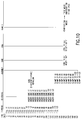
- Figure 8 is a graph plotting voltage vs. cps;
- Figure 9 is a graph plotting voltage vs. time;
- Figure 10 is a table of process steps in a timed sequence;
- Figure 11 is a graph plotting hardness vs. spin rate;
- Figure 12 is a graph plotting initial velocity vs. wound ball size;
- Fig. 13 is a front elevational view of an alternative embodiment of the core alignment device;
- Fig. 13a is a side elevational view of the alignment device;
- Fig. 14 is a sectional view along line 14-14 of Fig. 3; and
- Fig. 15 is a plan view of a mold half with a horizontal aligning rail unit.
- Turning to the Figures, and in particular to Figures 1 and 2, dipping
apparatus 10 includes adip tank 12 filled tolevel 12a and agitated byelectric mixer 12m.Apparatus 10 also includesoval conveying rack 13 withball core carriers 16.Dip tank 12 is filled withlatex bath 12b tolevel 12a and, if latex has been intank 12 for a substantial length of time, initial mixing ofbath 12b intank 12 should be carried out until uniformity ofbath 12b is reached. After such mixinggolf ball cores 14 are loaded atloading station 15 intoholding carriers 16 each comprising astem 16a and aholder ring 16b. Duringnormal operation tank 12 is agitated byelectric mixer 12m. Loadedcarriers 16 are carried by conveyingrack 13 along and down to dipcores 14 for 1 to 60 seconds intolatex bath 12b.Rack 13 moves through a descendingportion 20, dippingportion 22 and ascendingportion 24 of the carrier circuit to accomplish the latex dip core treatment. In wound cores the latex encapsulates the core with penetrate to a depth of about 0.050 inch and in solid cores the latex forms an encapsulating coating on the core of 0.001-0.010 inches thick. - After the
ball cores 14exit dip tank 12, they pass into acuring chamber 25 in which heat, ultraviolet rays, or other means for accelerating cure may be applied. It will be understood that some latex bath materials cure sufficiently under ambient conditions that curingchamber 25 is not required. Cores are unloaded atunload station 21. - In accordance with this invention,
wound cores 14 preferably are latex dipped while dipping ofsolid cores 14 is optional. Depending on the nature of the latex material applied, the golf ball dip-treatedcores 14 can then be stored for a period of time for additional cure, or, if the latex material is sufficiently cured at this point, the wound cores with the latex dip encapsulate can be transported directly to the molding area for molding of the cover material. - Since the latex material generates low levels of ammonia fumes in the
dip tank 12, it is preferred to have avacuum hood 23 positioned above thedip tank 12. Thevacuum hood 23 is preferably provided with means (not shown) for generating a clean air curtain about the periphery of thedip tank 12 to prevent escape of undesirable gasses. Thecuring chamber 25 can also be provided with suitable gas removal means. - As described above, the initial step of the process of the present invention is the dipping of the core in a latex bath. The preferred core is a wound core but any core, molded or wound, may be treated by the present process. With a molded core the advantage of such latex dip treatment is the increased velocity attainable to golf balls made with such cores. With a wound core the advantages are increased velocity, reduction of flow of air into the cover material during cover formation and prevention of rubber strand unravelling.
- It is important that a thermosetting, not a thermoplastic, latex be employed so that the arrangement of the cover material to the core encapsulated will not soften the encapsulating envelope and permit air to pass through it into the interstices in the windings of the wound core or allow the rubber strands to unravel.
- The thermosetting latex materials which are useful in the present invention are any materials which will withstand the temperatures at which the cover material is to be applied. This temperature will, of course, depend upon the particular fluidization temperature of the selected cover material. Typical thermosetting latex materials which can be used are: low ammonia, natural latex or pre-vulcanized natural latex with or without penetrant. When using a polyurethane cover material, it has been found that pre-vulcanized natural latex is particularly suitable.
- The preferred latex material, Heveatex brand Model H1704 pre-vulcanized natural latex, is a partially pre-vulcanized material which has a 60%-30% water dilution solids content. The preferred penetrant material is Niaproof #4 (tetra decyl sulfate) sold by Niacet Corp. It is understood that non-latex encapsulating materials may also be used.
- After latex coating, the cover is formed around the coated core by mixing and introducing the material in mold halves. Once mixed, an exothermic reaction commences and continues. It is important that the viscosity be measured over time, so that the subsequent steps of filling each mold half, introducing the core into one half and closing the mold can be properly timed for accomplishing centering of the core cover halves fusion and achieving overall uniformity.
- The increase in the viscosity of the urethane mix over time is measured by Vibrating Needle Curemeter (VNC) manufactured by Rapra Technology Limited. It is achieved by suspending a steel needle in the curing formulation. The needle is vibrated vertically by a small electrodynamic vibrator driven by a signal generator. Resistance to its movement is ultimately recorded as the voltage output. Suitable viscosity range of the curing urethane mix for introducing
cores 14 into the mold halves 51, 59 is determined to be approximately between 2,000 cps - 30,000 cps or between 60 mv - 98 mv voltage output with the preferred range of 8,000 to 15,000 cps (see Fig. 8). The time (gel time) at which the desired viscosity range occurs for mold mating is measured from first introduction of mix into the tophalf mold 51a. - The dip coating of latex penetrates the interstices, crevices and openings between the wound core threads to a depth of a fraction of an inch preferable about 0.050 inches and, as solidified, prevents a substantial quantity of air from flowing from the interior of the core into the cover during its formation. A negligible amount of the latex remains on the outside of the wound core. With solid cores about 0.001-0.010 inches is coated on the surface thus reducing the cover thickness by that amount. Small amounts of air passing through or around the latex coating are not large enough to create noticeable imperfections in the cover as determined by visual inspection.
- Turning to Fig. 3 and 3a, another step of the process is the formation of the cover on the
wound core 12. To accomplish this step a centering fixture is used.Fixture unit 30 includesbox frame 32, stationarycentral guide mount 34 comprising fixedcylinder 35 andstationary guide block 37.Guide block 37 has two (2)parallel passageways movable rods Rods cup frame unit 44, throughback piece 40, whichunit 44 carriesball cup 46 mounted oncup plate 44b as described (see Fig. 3a).Ball cup 46 holdsball core 14 through reduced pressure (or partial vacuum) inhose 46a. Ballcup frame unit 44 includesbase plate 44b,central opening 44a andupstanding back plate 44c.Back support 40 is secured to backplate 44c.Ball cup 46 is adjustably secured tocup plate 44b throughadjustable fasteners 49a, b which ride inslots Cup 46 can be adjusted vis-a-vis plate 44b front and back along arrow A (Fig. 4). - To initially align
ball core cup 46 in the proper position for molding of cover material, a machined metal set-upmold 50 is used. Set-upmold 50 is positioned by loweringunit 44 to permitpins alignment holes mold 50.Rails mold 50 underunit 44 and aftermold 50 is properly aligned it is spaced a few thousandths of an inch from eachrail 53, 56 (Fig. 7). Withball cup 46 free through loosenedfasteners 49a, b, alignment ofcup 46 is accomplished by loweringball cup 46 until it sits on and contacts set-up core 70.Fasteners 49a, b are tightened when flush contact withball cup 46 and set-up core 70 has been made. Next,mechanical stop 39b is tightened in this position.Frame unit 44 is then raised from set-upmold 50 and set-upmold 50 is removed fromfixture 30. - More than one
fixture unit 30 is used in the practice of this invention. Withfixture unit 30 so aligned, the set-upmold 50 is removed and is ready to be replaced with aball core 14 and a series of regular mold halves 51b, 51c, etc. - The core is centered by
fixture unit 30 in the top mold half, as then inverted, to a tolerance of about 0.010 of an inch. Such tolerance is described by determining the theoretical center of the core in the mold half and tolerating the actual core center, as fixtured, to be located up to .005 of an inch in any direction for the theoretical center. Since the actual center is tolerated to move .005 inch in any direction from the theoretical center, it can move over a range of 0.010 of an inch. - Turning to Figs. 13-15, prime numbered elements correspond to elements on Figs. 3-5. This alternative embodiment aligns each
mold half fixture frame base 30b of frame 30' using a horizontalrail alignment unit 66 which includesstationary mount block 66m, positioned onfixture base 30b, a raisedhorizontal cross piece 66c which carries two (2)parallel alignment rails end indentations mold indentation horizontal wall vertical wall Rails tips block 66m it is aligned and the mold half 51' is thereafter accurately positioned as pins 72' and 73' engage and move, as necessary, the mold half 51' during fixture descent. The spacings betweenblock 66m andrails mold 51 are exaggerated in Fig. 15. These tolerances are small enough to achieve the centering tolerances set out below. - Vertical position of
core 14 in ball cup 46' is accomplished usingmachined collars collars collars cup plate 44b and mold halves 51', 59' and thereafter the position of core 14 (not shown) in cup 46'. Cup 46' is not adjustable in this embodiment but is held in fixed relationship toplate 44b' withfasteners 83a-c. - As in the other fixture embodiment,
core 14 can, using this embodiment, be located up to .005 of an inch in any direction from the theoretical center. - Prior to proceeding with cover formation regular mold halves 51b, 51c are preheated to 140-180°F, the prepolymer is preheated and degassed at 140-160°F and the curative is also preheated and degassed at a temperature of 140-160°F. As so preheated, the prepolymer and curative both have approximately viscosities of 2000 cps.
- The cover material used in the present method is polyurethane which is the product of a reaction between a polyurethane prepolymer and a curing agent. The polyurethane prepolymer is a product formed by a reaction between a polyol and a diisocyanate. The curing agent is either a polyamine or glycol. A catalyst may be employed to promote the reaction between the curing agent and the polyurethane prepolymer.
- Suitable polyurethane prepolymers for use in the present invention are made from a polyol, such as polyether, polyester or polylactone, and a diisocyanate. Suitable diisocyanates for use in the present invention include 4,4'-diphenylmethane diisocyanate (MDI) and 3,3'-dimethyl-4,4'-biphenylene diisocyanate (TODI) and toluene diisocyanate (TDI).
- Suitable polyether polyols include polytetramethylene ether glycol; poly(oxypropylene) glycol; and polybutadiene glycol. Suitable polyester polyols include polyethylene adipate glycol; polyethylene propylene adipate glycol; and polybutylene adipate glycol. Suitable polylactone polyols include diethylene glycol initiated caprolactone; 1,4-butanediol initiated caprolactone; trimethylol propane initiated caprolactone; and neopentyl glycol initiated caprolactone. The preferred polyols are polytetramethylene ether glycol; polyethylene adipate glycol; polybutylene adipate glycol; and diethylene glycol initiated caprolactone.
- Suitable curatives for use in the present invention are selected from the slow-reacting polyamine group consisting of 3,5-dimethylthio-2,4-toluenediamine; 3,5-dimethylthio-2,6-toluenediamine; N,N'-dialkyldiamino diphenyl methane; trimethylene-glycol-di-p-aminobenzoate; polytetramethyleneoxide-di-p-aminobenzoate; or a difunctional glycol; and mixtures thereof. 3,5-dimethylthio-2,4-toluenediamine and 3,5-dimethylthio-2,6-toluenediamine are isomers and are sold under the trade name ETHACURE® 300 by Ethyl Corporation. Trimethylene glycol-di-p-aminobenzoate is sold under the trade name POLACURE 740M and polytetramethyleneoxide-di-p-aminobenzoates are sold under the trade name Polamine by Polaroid Corporation. N,N'-dialkyldiamino diphenyl methane is sold under the trade name UNILINK® by UOP.
- Suitable difunctional glycols are 1,4-butanediol; 1,3-butanediol; 2,3-butanediol; 2,3-dimethyl-2,3-butanediol; dipropylene glycol; and ethylene glycol. Difunctional glycols are inherently slow-reacting.
- To start the cover formation, mixing of the prepolymer and curative is accomplished in motorized mixer 60 (Fig. 6) including mixing
head 61 by feeding throughlines mixer 60 is cooled by coolingjacket 66. Due to the exothermic reaction of prepolymer and curative as mixed, the mixing head temperature will tend to rise. To control such a rise, the mixing head temperature is maintained by cooling in a range appropriate for the specific urethane material and to attain a workable gel time. From the time mixing commences until the reacting material is fed into eachtop mold 51a, b, c, etc. orbottom mold half 59a, b, c etc. is about 4-7 seconds. Toppreheated mold halves 51a, b, c etc. are filled and placed infixture unit 30 usingpins holes mold 51a, b, c etc. After the reacting materials have resided intop mold halves 51a, b, c, etc. for about 50-80 seconds, acore 14 is lowered at a controlled speed into the gelling reacting mixture by loweringframe unit 44 using an pneumatic powered arrangement not shown. Alternatively, electric or hydraulic systems may be used. Controlled lowering is accomplished by adjustment of the powered arrangement and by use of pneumatic controls not shown to lessen and preferably prevent air bubbles. Stop 39b limits movement downward. The amount of mixture introduced into eachmold half 51a is 5.4-5.7 g. At a later time abottom mold half 59 of a series ofbottom mold halves 59a, 59b, etc. has similar mixture amounts introduced into its cavity 58 (Fig. 6). - Upon location of the
coated core 14 inhalves mold 51a, b, c after gelling for 50-80 seconds, the vacuum is released inline 46a allowing core 14 to be released.Mold halves 51a, b, c withcore 14 and solidifiedcover half 80 thereon is removed from the centeringfixture unit 30, inverted (see Fig. 6) and mated withother mold halves 59a, b, c which, at an appropriate time earlier have had a selected quantity of reacting polyurethane prepolymer and curing agent introduced therein to commence gelling. - When a plurality of
mold halves 51a, b, c etc. and 59a, b, c etc. are filled and clamped at one time, the following time sequence is preferred. - The sequence of introducing the polyurethane mix into the
top mold half 51a (1T) and its mate thebottom mold half 59a (1B) is as follows: Introduction of the mixed prepolymer and curative into thetop mold 51a starts the time sequence which start is referred to herein as time zero. The tophalf mold 51a receives the mix first at time zero and shortly mold half is placed infixture unit 30. The core is initially inserted in the mix located intop mold 51a attime 60 seconds (see Fig. 10). Attime 72 seconds,bottom mold half 59a (1B) is filled and attime 132 seconds, themold halves time 126 seconds, the mix has been intop half 51a - The thorough mixing that takes place in
mixer 60 for the period of time described provides an improved cover material. Mold halves 51, 53 are pre-heated to 160-190°F. The core is held in its fully-down position for 30-40 seconds and the vacuum is then released. Following clamping of mold halves, the clamped mold is put in a curing oven for approximately 10 minutes to reach a mold temperature of 140-180°F followed by cooling for approximately 10 minutes to reach a mold temperature of 50-70°F. - The mold halves are clamped together under 400-600 psi pressure. The mold halves each contains sufficient reacting material to form hemispherical portions of the cover. Mold halves are held together for 10-15 minutes and thereafter cooled from 140°F-180°F to 50°F-70°F and then opened to demold the ball. Excess polyurethane is extruded from the mold cavity into sprue channels 51s forming solidified sprues not shown.
- A wound center was dipped in a 30% pre-vulcanized latex solution, drained and partially dried in a current of warm air. Remainder of drying was accomplished at room temperature. Latex penetration was approximately 50 mils. A mold half was preheated to approximately 160°F.
- A mixture of 100 parts of Betathane 23.711, an MDI-based polyether prepolymer, 5.19 parts of titanium dioxide dispersion and 48.27 parts of Polamine 250 was prepared. Approximately 5.6g of this mixture was dispensed into a heated mold cavity and allowed to thicken for approximately one minute. A dipped wound core with a diameter of 1.580" was placed in the bottom mold cavity by means of the centering fixture shown in Figure 3. The core was held in a concentric position for approximately 40 seconds to allow the material to thicken further to support the core. The top heated mold half was then filled and the material allowed to thicken for approximately 1 minute. The top and bottom mold halves were then assembled and clamped by bolts or any conventional manner. The assembled mold was introduced into a curing oven and cured for 10 minutes at approximately 160°F. The assembled mold was then introduced into a cooling chamber for approximately 10 minutes to reach a mold temperature of 50-70°F.
- The resulting cover was approximately 50 mils thick on a side and had a Shore D durometer of approximately 58-60 when measured after a two-day waiting period. Subsequently, the ball was painted and the cover was observed to be highly abrasion and cut resistant. Spin rate of this ball was approximately 100-200 rpm lower than a balata covered ball(Tour 100) with an acceptable velocity of 252.7 ft/sec.
- The steps of Example I were carried out except that the wound core was not dipped in a latex solution.
- The steps of Example I were carried out except that a solid core was used.
- The steps of Example I were carried out with a solid core without a latex dip.
- A range of core sizes that can be employed in this invention, whether dipped or non-dipped, is 1.560" to 1.610" was determined by previous testing that as core size of the ball increases, ball velocity increases (Fig. 11). However, if the durometer of the cover remains the same, spin rate of the ball was materially unaffected. Spin rate can be changed by modifying the durometer of the cover by selecting different ratios of materials or combining other materials. Cover durometers of 48 Shore D to 72 Shore D are attainable with the preferred range of 58-62 for this type of ball.
- The relationship between durometer and spin rate was determined to be linear with harder durometer covers producing lower spin rates (Fig. 12).
Claims (29)
- In a method of making a golf ball using a core holder and first and second mold halves with the first mold half positioned below such core holder, the improvement comprisinga) placing a core in a movable fixture;b) placing polyurethane in a selected state of gel in the first mold half;c) causing the fixture means with the core holder to descend against such polyurethane and causing thereafter the fixture means to move at a controlled rate against the polyurethane toward the first mold half;d) as core downward movement continues, molding a quantity of partially gelled polyurethane around one half of the core in such first mold half;e) disengaging the core from the core holder;f) thereafter placing such core with its partially cured polyurethane cover while still in said first mold half against a second mold half having polyurethane at a selected state of gel therein and mating the two half molds together; andg) heating the mated halves to further cure the polyurethane, cooling the mated halves and thereafter opening the mold.
- In a method of making a golf ball using a core holder and first and second mold halves with the first mold half positioned below such core holder, the improvement comprisinga) encapsulating the core with an encapsulating material;b) placing the encapsulated core in a movable fixture;c) placing polyurethane in a selected state of gel in the first mold half;d) causing the fixture means with the core holder to descend against such polyurethane and causing thereafter the fixture means to move at a controlled rate against the polyurethane toward the first mold half;e) as core downward movement continues, molding a quantity of partially gelled polyurethane around one half of the core in such first mold half;f) disengaging the core from the core holder;g) thereafter placing such core with its partially cured polyurethane cover while still in said first mold half against a second mold half having polyurethane at a selected state of gel therein and mating the two half molds together; andh) heating the mated halves to further cure the polyurethane, cooling the mated halves and thereafter opening the mold.
- The method of claim 2 in which a solid core is covered with a layer of latex about 0.001-0.010 inch thick.
- The method of claim 2 in which a wound core is impregnated with a layer of latex which penetrates into the core to a depth of about 0.050 inch.
- The method of claim 1 in which the first mold half is held by mold holding means preadjusted prior to descent of the fixture means.
- The method of claim 1 in which the core diameter is in the range of 1.560-1.610 inches.
- The method of claim 1 in which the polyurethane includes polyether polyols and polyamines.
- The method of claim 1 in which the rate of descent of the core on the fixture is such that no air bubbles are created as the core enters the polyurethane in the mold.
- Apparatus for molding a golf ball cover around a core comprising a fixture, a mold half and adjustable mold holding means in turn comprisinga) a guide frame;b) a holder frame movable up and down on a guide frame;c) a ball core holder adjustably mounted on the holder frame;d) alignment means for initially aligning the holder frame and the core ball holder prior to molding including a set mold half, mold guide rails, alignment pins and adjustment fasteners; f) limit means on the core frame to limit the downward travel of the core frame; andg) lowering means controlling the descent of portions of the core frame carrying the core ball holder to control the movement of the core into the mold.
- A golf ball having improved shear resistance, cut resistance and improved initial velocity comprising a core, and a molded polyurethane cover which ball is formed by the steps ofa) placing the core in a movable fixture;b) placing polyurethane in a selected state of gel in the first mold half and allowing gelling to continue;c) causing at a predetermined time the fixture means with the core holder to descend against such polyurethane and causing thereafter the fixture means to move at a controlled rate against the polyurethane toward the first mold half;d) as core downward movement continues molding a quantity of partially gelled polyurethane around one half of the core in such first mold half;e) disengaging the core from the core holder;f) thereafter placing such core with its partially cured polyurethane cover while still in said first mold half against a second mold half having polyurethane at a selected state of gel therein and mating with force the two half molds together; andg) heating the mated halves and further curing the polyurethane and thereafter opening the mold.
- A golf ball having improved shear resistance, cut resistance and improved initial velocity comprising a core, a layer of latex on or within the core and a molded polyurethane cover which ball is formed by the steps ofa) encapsulating the core in liquid latex;b) placing the encapsulated core in a movable fixture;c) placing polyurethane in a selected state of gel in the first mold half and allowing gelling to continue;d) causing at a predetermined time the fixture means with the core holder to descend against such polyurethane and causing thereafter the fixture means to move at a controlled rate against the polyurethane toward the first mold half;e) as core downward movement continues molding a quantity of partially gelled polyurethane around one half of the core in such first mold half;f) disengaging the core from the core holder;g) thereafter placing such core with its partially cured polyurethane cover while still in said first mold half against a second mold half having polyurethane at a selected state of gel therein and mating with force the two half molds together; andh) heating the mated halves and further curing the polyurethane and thereafter opening the mold.
- The golf ball of claim 11 having a wound core is penetrated with a layer of latex about 0.050 inch thick.
- The golf ball of claim 11 having a solid core is covered with a layer of latex about 0.001-0.010 inch thick.
- The golf ball of claim 10 in which the first mold half is held by mold holding means preadjusted for core centering prior to descent of the fixture means.
- The golf ball of claim 10 in which the polyurethane includes polyether polyols and polyamines.
- The golf ball of claim 10 in which the mix has resided in the first half mold for about 60 seconds when the core is introduced and resided in the second half mold about 55 seconds when the mold halves are clamped.
- The golf ball of claim 10 in which the core diameter is in the range of 1.560-1.610 inches.
- The method of claim 1 in which the mold halves are preheated.
- The method of claim 2 in which polyurethane includes a polyurethane prepolymer and a curing agent which are mixed and thereafter gel for 50-80 seconds before the step of disengaging the core from the core holder.
- The method of claim 5 in which molding means is preadjusted by the steps of releasing the mold holding means, causing a set-up core attached to the movable fixture to descend into the first mold half to move the mold holding means and thereafter securing the mold holding means in a fixed place.
- The method of claim 18 in which the preheating temperature is in the range of 140°F to 180°F range.
- The method of claim 2 in which the first and second quantity of polyurethane each are composed of a prepolymer and a curative and in which the first quantity is mixed and has cured for substantially the same length of time as the second quantity when the first and second molds are finally engaged with the core.
- The method of claim 1 in which the quantity of polyurethane including prepolymer and curing agent in the first half mold is allowed to thicken after mixing of the prepolymer and curing agent about one hundred seconds prior to release of the core by the core holder and in which the quantity of polyurethane in the second mold half thickens for sixty seconds prior to mating of the halves.
- The method of claim 1 in which the core diameter is in the range of 1.560-1.610 inches.
- The method of claim 1 in which the polyurethane is a product of the reaction between a polyurethane prepolymer and a curing agent with the polyurethane prepolymer being a product formed by a reaction between a polyol and a diisocyanate.
- The method of claim 25 in which the prepolymer is a 4,4'-diphenylmethane diisocyanate and a polyether type polyol.
- The method of claim 25 in which the curing agent is polytetramethyleneoxide-di-p-amino benzoate.
- In a method of making a golf ball using a core holder and first and second mold halves with the first mold half positioned below such core holder, the improvement comprisinga) placing a core in such core holder which in turn is held by a movable fixture;b) placing polyurethane in the first mold half;c) holding the first mold half by mold holding means prior to the movement of said movable fixture, which mold holding means is accomplished by steps ofi) releasing the mold holding means;ii) causing pins with collar means thereon attached to the movable fixture to engage the first mold half bushing means to align the first half mold to control the positions in horizontal directions and the depth of core insertion into the polyurethane;d) causing the movable fixture means with the core holder to descend against such polyurethane when such polyurethane is in a selected state of gel and causing thereafter the movable fixture to move at a controlled rate against the polyurethane toward the first mold half;e) as core downward movement continues, molding a quantity of partially gelled polyurethane around one half of the core in such first mold half;f) disengaging the core from the core holder after a selected period of time;g) thereafter placing such core with its partially cured polyurethane cover while still in said first mold half against a second mold half having polyurethane at a selected state of gel therein and mating the two half molds together; andh) heating the mated halves to further cure the polyurethane cooling the mated halves and thereafter opening the mold.
- A method of claim 1 in which the movable fixture is first mounted on frame means for reciprocal movement thereon and in which each first mold half is positioned with respect to said fixture between guide means affixed to said frame means and collared pin means on the movable fixture accurately locate the mold half as the fixture descends whereby the core on the movable fixture is locatable with respect to the first mold half.
Priority Applications (1)
| Application Number | Priority Date | Filing Date | Title |
|---|---|---|---|
| EP99121575A EP0978362A3 (en) | 1994-01-21 | 1995-01-10 | Method and apparatus for forming polyurethane cover on golf ball core |
Applications Claiming Priority (2)
| Application Number | Priority Date | Filing Date | Title |
|---|---|---|---|
| US185667 | 1988-04-25 | ||
| US18566794A | 1994-01-21 | 1994-01-21 |
Related Child Applications (1)
| Application Number | Title | Priority Date | Filing Date |
|---|---|---|---|
| EP99121575A Division EP0978362A3 (en) | 1994-01-21 | 1995-01-10 | Method and apparatus for forming polyurethane cover on golf ball core |
Publications (2)
| Publication Number | Publication Date |
|---|---|
| EP0664206A2 true EP0664206A2 (en) | 1995-07-26 |
| EP0664206A3 EP0664206A3 (en) | 1997-06-04 |
Family
ID=22681960
Family Applications (2)
| Application Number | Title | Priority Date | Filing Date |
|---|---|---|---|
| EP99121575A Withdrawn EP0978362A3 (en) | 1994-01-21 | 1995-01-10 | Method and apparatus for forming polyurethane cover on golf ball core |
| EP95100257A Withdrawn EP0664206A3 (en) | 1994-01-21 | 1995-01-10 | Method and apparatus for forming polyurethane cover on golf ball core. |
Family Applications Before (1)
| Application Number | Title | Priority Date | Filing Date |
|---|---|---|---|
| EP99121575A Withdrawn EP0978362A3 (en) | 1994-01-21 | 1995-01-10 | Method and apparatus for forming polyurethane cover on golf ball core |
Country Status (5)
| Country | Link |
|---|---|
| EP (2) | EP0978362A3 (en) |
| JP (1) | JPH0847553A (en) |
| AU (1) | AU1012295A (en) |
| CA (1) | CA2140169A1 (en) |
| ZA (1) | ZA95216B (en) |
Cited By (6)
| Publication number | Priority date | Publication date | Assignee | Title |
|---|---|---|---|---|
| EP0977617A4 (en) * | 1998-02-25 | 2000-02-09 | Dunlop Maxfli Sports Corp | Polyurethane material for two and three piece golf balls and method |
| US6713007B2 (en) | 2000-11-27 | 2004-03-30 | Sumitomo Rubber Industries, Ltd. | Method of making a golf ball |
| US6719646B2 (en) | 2000-01-25 | 2004-04-13 | Dunlop Slazenger Sports | Polyurethane covered three-piece golf ball |
| US7244384B1 (en) | 1998-02-04 | 2007-07-17 | Taylormade-Adidas Golf Company | Method for manufacturing two and three piece golf balls constructed from polyurethane material |
| WO2008023118A2 (en) * | 2006-08-22 | 2008-02-28 | Societe Nationale Des Chemins De Fer Francais - Sncf - Ids-J | Protection module for removable data storage medium and a production method thereof |
| KR101778001B1 (en) | 2016-03-16 | 2017-09-14 | 경상대학교산학협력단 | Movable mold and Method for rapid heating and cooling |
Families Citing this family (6)
| Publication number | Priority date | Publication date | Assignee | Title |
|---|---|---|---|---|
| WO1998028048A1 (en) * | 1996-12-24 | 1998-07-02 | Bridgestone Sports Co., Ltd. | Process for producing golf ball |
| US6213892B1 (en) * | 1999-07-27 | 2001-04-10 | Callaway Golf Company | Multi-layer golf ball |
| US6290615B1 (en) | 1999-11-18 | 2001-09-18 | Callaway Golf Company | Golf ball having a tubular lattice pattern |
| JP4562933B2 (en) * | 2001-03-15 | 2010-10-13 | Sriスポーツ株式会社 | Golf ball having a urethane cover |
| JP4531313B2 (en) * | 2001-09-26 | 2010-08-25 | Sriスポーツ株式会社 | Golf ball having a urethane cover |
| US7163471B2 (en) | 2003-01-10 | 2007-01-16 | Taylor Made Golf Company, Inc. | Golf balls having sound-altered layers and methods for making them |
Citations (5)
| Publication number | Priority date | Publication date | Assignee | Title |
|---|---|---|---|---|
| US2361348A (en) * | 1939-10-12 | 1944-10-24 | Spalding A G & Bros Inc | Process and apparatus for making balls |
| US3068522A (en) * | 1960-07-19 | 1962-12-18 | David L Nickerson | Method and apparatus for molding covers on spherical bodies |
| WO1987001673A1 (en) * | 1985-09-18 | 1987-03-26 | Packaging Corporation International | Cannular feeding apparatus |
| EP0241009A2 (en) * | 1986-04-08 | 1987-10-14 | Zenhäusern, Heinrich Stephan | Method and moulding device for producing climbing-irons for insertion into masonry work |
| EP0578466A1 (en) * | 1992-07-06 | 1994-01-12 | Acushnet Company | Method and apparatus for forming polyurethane cover on golf ball core |
Family Cites Families (3)
| Publication number | Priority date | Publication date | Assignee | Title |
|---|---|---|---|---|
| US2376085A (en) * | 1939-10-11 | 1945-05-15 | Spalding A G & Bros Inc | Process and apparatus for making balls and improved balls |
| US2329839A (en) * | 1940-04-15 | 1943-09-21 | Erwin Huebsch | Apparatus for making golf balls |
| IT1238414B (en) * | 1989-12-19 | 1993-07-26 | PLANT AND PROCESS FOR THE FORMING OF ELASTOMERS. |
-
1995
- 1995-01-10 EP EP99121575A patent/EP0978362A3/en not_active Withdrawn
- 1995-01-10 EP EP95100257A patent/EP0664206A3/en not_active Withdrawn
- 1995-01-11 AU AU10122/95A patent/AU1012295A/en not_active Abandoned
- 1995-01-12 ZA ZA95216A patent/ZA95216B/en unknown
- 1995-01-13 CA CA002140169A patent/CA2140169A1/en not_active Abandoned
- 1995-01-23 JP JP7007972A patent/JPH0847553A/en active Pending
Patent Citations (5)
| Publication number | Priority date | Publication date | Assignee | Title |
|---|---|---|---|---|
| US2361348A (en) * | 1939-10-12 | 1944-10-24 | Spalding A G & Bros Inc | Process and apparatus for making balls |
| US3068522A (en) * | 1960-07-19 | 1962-12-18 | David L Nickerson | Method and apparatus for molding covers on spherical bodies |
| WO1987001673A1 (en) * | 1985-09-18 | 1987-03-26 | Packaging Corporation International | Cannular feeding apparatus |
| EP0241009A2 (en) * | 1986-04-08 | 1987-10-14 | Zenhäusern, Heinrich Stephan | Method and moulding device for producing climbing-irons for insertion into masonry work |
| EP0578466A1 (en) * | 1992-07-06 | 1994-01-12 | Acushnet Company | Method and apparatus for forming polyurethane cover on golf ball core |
Cited By (9)
| Publication number | Priority date | Publication date | Assignee | Title |
|---|---|---|---|---|
| US7244384B1 (en) | 1998-02-04 | 2007-07-17 | Taylormade-Adidas Golf Company | Method for manufacturing two and three piece golf balls constructed from polyurethane material |
| EP0977617A4 (en) * | 1998-02-25 | 2000-02-09 | Dunlop Maxfli Sports Corp | Polyurethane material for two and three piece golf balls and method |
| EP0977617A1 (en) * | 1998-02-25 | 2000-02-09 | Dunlop Slazenger Group Americas Inc | Polyurethane based two and three piece golf balls |
| US6719646B2 (en) | 2000-01-25 | 2004-04-13 | Dunlop Slazenger Sports | Polyurethane covered three-piece golf ball |
| US6713007B2 (en) | 2000-11-27 | 2004-03-30 | Sumitomo Rubber Industries, Ltd. | Method of making a golf ball |
| WO2008023118A2 (en) * | 2006-08-22 | 2008-02-28 | Societe Nationale Des Chemins De Fer Francais - Sncf - Ids-J | Protection module for removable data storage medium and a production method thereof |
| FR2905224A1 (en) * | 2006-08-22 | 2008-02-29 | Sncf | PROTECTIVE MOLD FOR REMOVABLE MEMORY HOLDER AND METHOD FOR MAKING SAME |
| WO2008023118A3 (en) * | 2006-08-22 | 2008-04-10 | Chemins De Fer Francais Sncf I | Protection module for removable data storage medium and a production method thereof |
| KR101778001B1 (en) | 2016-03-16 | 2017-09-14 | 경상대학교산학협력단 | Movable mold and Method for rapid heating and cooling |
Also Published As
| Publication number | Publication date |
|---|---|
| AU1012295A (en) | 1995-08-03 |
| EP0664206A3 (en) | 1997-06-04 |
| CA2140169A1 (en) | 1995-07-22 |
| ZA95216B (en) | 1995-09-08 |
| EP0978362A3 (en) | 2000-09-20 |
| JPH0847553A (en) | 1996-02-20 |
| EP0978362A2 (en) | 2000-02-09 |
Similar Documents
| Publication | Publication Date | Title |
|---|---|---|
| US5733428A (en) | Method for forming polyurethane cover on golf ball core | |
| US6371870B1 (en) | Solid golf ball with cast cover | |
| EP0578466B1 (en) | Method and apparatus for forming polyurethane cover on golf ball core | |
| US3177280A (en) | Process for the manufacture of polyurethane coated balls | |
| EP0664206A2 (en) | Method and apparatus for forming polyurethane cover on golf ball core | |
| US6685455B2 (en) | Golf ball casting mold | |
| US6936205B2 (en) | Method of making golf balls | |
| US6787091B2 (en) | Reaction injection and compression molding of a golf ball | |
| US3981955A (en) | Method of rotational molding reinforcer-incorporated plastics | |
| US4123307A (en) | Method for forming hollow shells by rotational casting and winding thereon | |
| JP3937044B2 (en) | Polyurethane material for two-piece and three-piece golf balls and manufacturing method | |
| US2958907A (en) | Method of producing insulating containers | |
| GB2144073A (en) | Stretching and blow molding apparatus | |
| WO2001056765A1 (en) | A golf ball casting mold assembly | |
| US4206170A (en) | Method of molding a torus shaped article | |
| CA2199602A1 (en) | Method and device for producing pipes or tubular moulded bodies from polymer concrete | |
| US3932107A (en) | Apparatus for forming composite articles | |
| JP2002535160A (en) | Method for producing glass fiber reinforced synthetic material tube by centrifugation | |
| US7214338B2 (en) | Method and device for producing an electric insulator made from plastic | |
| EP4003752A1 (en) | Method of assembling a bicycle rim, bicycle rim | |
| JPH04500432A (en) | A method and apparatus for embedding the inside of an indoor electrical appliance, such as a proximity detector, in a resin, and a container for the electrical appliance and appliance related thereto. | |
| EP0561414B1 (en) | Casting method for forming a resin molding | |
| JPS6372448A (en) | Method and device for forming part | |
| JP3083751B2 (en) | Resin molding method and molding apparatus therefor | |
| GB2034239A (en) | Process for the Production of Low Weight Synthetic Plastics Bodies |
Legal Events
| Date | Code | Title | Description |
|---|---|---|---|
| PUAI | Public reference made under article 153(3) epc to a published international application that has entered the european phase |
Free format text: ORIGINAL CODE: 0009012 |
|
| AK | Designated contracting states |
Kind code of ref document: A2 Designated state(s): FR GB SE |
|
| PUAL | Search report despatched |
Free format text: ORIGINAL CODE: 0009013 |
|
| AK | Designated contracting states |
Kind code of ref document: A3 Designated state(s): FR GB SE |
|
| 17P | Request for examination filed |
Effective date: 19971203 |
|
| 17Q | First examination report despatched |
Effective date: 19990415 |
|
| GRAG | Despatch of communication of intention to grant |
Free format text: ORIGINAL CODE: EPIDOS AGRA |
|
| GRAG | Despatch of communication of intention to grant |
Free format text: ORIGINAL CODE: EPIDOS AGRA |
|
| GRAH | Despatch of communication of intention to grant a patent |
Free format text: ORIGINAL CODE: EPIDOS IGRA |
|
| STAA | Information on the status of an ep patent application or granted ep patent |
Free format text: STATUS: THE APPLICATION IS DEEMED TO BE WITHDRAWN |
|
| 18D | Application deemed to be withdrawn |
Effective date: 20010512 |