EP0661446B1 - A fuel injector with an integrated spark plug for a direct injection type engine - Google Patents
A fuel injector with an integrated spark plug for a direct injection type engine Download PDFInfo
- Publication number
- EP0661446B1 EP0661446B1 EP94118724A EP94118724A EP0661446B1 EP 0661446 B1 EP0661446 B1 EP 0661446B1 EP 94118724 A EP94118724 A EP 94118724A EP 94118724 A EP94118724 A EP 94118724A EP 0661446 B1 EP0661446 B1 EP 0661446B1
- Authority
- EP
- European Patent Office
- Prior art keywords
- insulator
- spark plug
- fuel injector
- fuel
- direct injection
- Prior art date
- Legal status (The legal status is an assumption and is not a legal conclusion. Google has not performed a legal analysis and makes no representation as to the accuracy of the status listed.)
- Expired - Lifetime
Links
Images


Classifications
-
- F—MECHANICAL ENGINEERING; LIGHTING; HEATING; WEAPONS; BLASTING
- F02—COMBUSTION ENGINES; HOT-GAS OR COMBUSTION-PRODUCT ENGINE PLANTS
- F02M—SUPPLYING COMBUSTION ENGINES IN GENERAL WITH COMBUSTIBLE MIXTURES OR CONSTITUENTS THEREOF
- F02M51/00—Fuel-injection apparatus characterised by being operated electrically
- F02M51/06—Injectors peculiar thereto with means directly operating the valve needle
- F02M51/061—Injectors peculiar thereto with means directly operating the valve needle using electromagnetic operating means
- F02M51/0625—Injectors peculiar thereto with means directly operating the valve needle using electromagnetic operating means characterised by arrangement of mobile armatures
- F02M51/0664—Injectors peculiar thereto with means directly operating the valve needle using electromagnetic operating means characterised by arrangement of mobile armatures having a cylindrically or partly cylindrically shaped armature, e.g. entering the winding; having a plate-shaped or undulated armature entering the winding
- F02M51/0671—Injectors peculiar thereto with means directly operating the valve needle using electromagnetic operating means characterised by arrangement of mobile armatures having a cylindrically or partly cylindrically shaped armature, e.g. entering the winding; having a plate-shaped or undulated armature entering the winding the armature having an elongated valve body attached thereto
- F02M51/0675—Injectors peculiar thereto with means directly operating the valve needle using electromagnetic operating means characterised by arrangement of mobile armatures having a cylindrically or partly cylindrically shaped armature, e.g. entering the winding; having a plate-shaped or undulated armature entering the winding the armature having an elongated valve body attached thereto the valve body having cylindrical guiding or metering portions, e.g. with fuel passages
- F02M51/0678—Injectors peculiar thereto with means directly operating the valve needle using electromagnetic operating means characterised by arrangement of mobile armatures having a cylindrically or partly cylindrically shaped armature, e.g. entering the winding; having a plate-shaped or undulated armature entering the winding the armature having an elongated valve body attached thereto the valve body having cylindrical guiding or metering portions, e.g. with fuel passages all portions having fuel passages, e.g. flats, grooves, diameter reductions
-
- F—MECHANICAL ENGINEERING; LIGHTING; HEATING; WEAPONS; BLASTING
- F02—COMBUSTION ENGINES; HOT-GAS OR COMBUSTION-PRODUCT ENGINE PLANTS
- F02M—SUPPLYING COMBUSTION ENGINES IN GENERAL WITH COMBUSTIBLE MIXTURES OR CONSTITUENTS THEREOF
- F02M51/00—Fuel-injection apparatus characterised by being operated electrically
- F02M51/005—Arrangement of electrical wires and connections, e.g. wire harness, sockets, plugs; Arrangement of electronic control circuits in or on fuel injection apparatus
-
- F—MECHANICAL ENGINEERING; LIGHTING; HEATING; WEAPONS; BLASTING
- F02—COMBUSTION ENGINES; HOT-GAS OR COMBUSTION-PRODUCT ENGINE PLANTS
- F02M—SUPPLYING COMBUSTION ENGINES IN GENERAL WITH COMBUSTIBLE MIXTURES OR CONSTITUENTS THEREOF
- F02M51/00—Fuel-injection apparatus characterised by being operated electrically
- F02M51/06—Injectors peculiar thereto with means directly operating the valve needle
- F02M51/061—Injectors peculiar thereto with means directly operating the valve needle using electromagnetic operating means
- F02M51/0625—Injectors peculiar thereto with means directly operating the valve needle using electromagnetic operating means characterised by arrangement of mobile armatures
-
- F—MECHANICAL ENGINEERING; LIGHTING; HEATING; WEAPONS; BLASTING
- F02—COMBUSTION ENGINES; HOT-GAS OR COMBUSTION-PRODUCT ENGINE PLANTS
- F02M—SUPPLYING COMBUSTION ENGINES IN GENERAL WITH COMBUSTIBLE MIXTURES OR CONSTITUENTS THEREOF
- F02M57/00—Fuel-injectors combined or associated with other devices
- F02M57/06—Fuel-injectors combined or associated with other devices the devices being sparking plugs
-
- F—MECHANICAL ENGINEERING; LIGHTING; HEATING; WEAPONS; BLASTING
- F02—COMBUSTION ENGINES; HOT-GAS OR COMBUSTION-PRODUCT ENGINE PLANTS
- F02M—SUPPLYING COMBUSTION ENGINES IN GENERAL WITH COMBUSTIBLE MIXTURES OR CONSTITUENTS THEREOF
- F02M61/00—Fuel-injectors not provided for in groups F02M39/00 - F02M57/00 or F02M67/00
- F02M61/16—Details not provided for in, or of interest apart from, the apparatus of groups F02M61/02 - F02M61/14
- F02M61/168—Assembling; Disassembling; Manufacturing; Adjusting
-
- F—MECHANICAL ENGINEERING; LIGHTING; HEATING; WEAPONS; BLASTING
- F02—COMBUSTION ENGINES; HOT-GAS OR COMBUSTION-PRODUCT ENGINE PLANTS
- F02B—INTERNAL-COMBUSTION PISTON ENGINES; COMBUSTION ENGINES IN GENERAL
- F02B2275/00—Other engines, components or details, not provided for in other groups of this subclass
- F02B2275/14—Direct injection into combustion chamber
-
- Y—GENERAL TAGGING OF NEW TECHNOLOGICAL DEVELOPMENTS; GENERAL TAGGING OF CROSS-SECTIONAL TECHNOLOGIES SPANNING OVER SEVERAL SECTIONS OF THE IPC; TECHNICAL SUBJECTS COVERED BY FORMER USPC CROSS-REFERENCE ART COLLECTIONS [XRACs] AND DIGESTS
- Y02—TECHNOLOGIES OR APPLICATIONS FOR MITIGATION OR ADAPTATION AGAINST CLIMATE CHANGE
- Y02T—CLIMATE CHANGE MITIGATION TECHNOLOGIES RELATED TO TRANSPORTATION
- Y02T10/00—Road transport of goods or passengers
- Y02T10/10—Internal combustion engine [ICE] based vehicles
- Y02T10/12—Improving ICE efficiencies
Description
Claims (10)
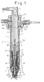
- A fuel injector with an integrated spark plug for a direct injection type engine, comprising:characterized in thatan electric conductor (3, 4, 5) disposed along the central axis, said electric conductor (3, 4, 5) being electrically coupled with a cable (2) for supplying electric current for a spark discharge;a needle valve (7) made of conductive material, said needle valve (7) being electrically coupled to said electric conductor (3, 4, 5) through a return spring (6) made of conductive material, said needle valve (7) being reciprocally moved by a solenoid (30);a needle housing (8) made of conductive material, said needle housing (8) receiving said needle valve (7) and having a center electrode (9) at its end;a grounding electrode (10) disposed to oppose said center electrode (9);an insulator (11, 12, 13, 14, 15) disposed outside of said electric conductor (3, 4, 5);an outer cylinder (21, 22, 26) disposed outside of said insulator (11, 12, 13, 14, 15), said outer cylinder (21, 22, 26) forming a uniform clearance which is used as a fuel passage; anda connector assembly (40) for connecting a fuel line and an electric cable (31) for supplying an electric current to said solenoid (30),
an inner wall of said outer cylinder (21, 22, 26) adheres to said insulator (11, 12, 13, 14, 15) so that said clearance is formed around an outer wall of said outer cylinder (21, 22, 26), and said needle housing (8) has a nozzle (9a) for injecting fuel and slidably receives said needle valve (7) so that a high voltage electric current passes from said needle valve (7) to said needle housing (8) irrespective of their relative positions. - A fuel injector with an integrated spark plug for a direct injection type engine according to claim 1,
characterized in that
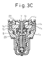
said center electrode (9) disposed at the end of said needle housing (8) projects beyond the needle seat portion of said needle housing (8), and said grounding electrode (10) is disposed radially outside the outside surface of said center electrode (9). - A fuel injector with an integrated spark plug for a direct injection type engine according to claim 1,
characterized in that
said insulator (15) is disposed around said needle housing (8) and is kept a predetermined distance away from the outer surface of said needle housing (8) for a predetermined distance from the end of said insulator (15). - A fuel injector with an integrated spark plug for a direct injection type engine according to claim 1,
characterized in that
said insulator (11, 12, 13, 14, 15) is axially separated into several pieces. - A fuel injector with an integrated spark plug for a direct injection type engine according to claim 4,
characterized in that
at their junction, two of said separated insulators (11, 12; 12, 13; 13, 14; 14, 15) are connected to each other in a nested relationship, the axial end of the outer portion of one (11, 12, 13, 14, 15) of said two of said separated insulators (11, 12; 12, 13; 13, 14; 14, 15) having a different axial position compared to the position of the axial end of the inner portion, said axial end of the outer portion which is contiguous at an edge with the outer surface of said insulator (11, 12, 13, 14, 15) which contacts with the inner wall of the outer cylinder (22, 25, 27, 29) being continuous in a stepped configuration with said axial end of the inner portion which is contiguous at an edge with the inner surface of said insulator (11, 12, 13, 14, 15) which contacts the centrally located conductor (4, 5, 6, 7) at an edge. - A fuel injector with an integrated spark plug for a direct injection type engine according to claim 1,
characterized in that
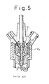
said solenoid (30) is surrounded with a ferrous magnetic material (22, 25, 26) so as to make a closed magnetic circuit. - A fuel injector with an integrated spark plug for a direct injection type engine according to claim 6,
characterized in that
the parts (21, 27) which connect to the said ferrous magnetic material (22, 25, 26) are made of non-magnetic materials so as to prevent the magnetism from leaking. - A fuel injector with an integrated spark plug for a direct injection type engine according to claim 1,
characterized in that
said needle housing (8) is connected to the outer insulator (15) by a threaded portion and adhesives are inserted into the clearance in the threaded portion. - A fuel injector with an integrated spark plug for a direct injection type engine according to claim 1,
characterized in that
said electric conductor (3, 4, 5) is made of an outer pipe (4) and an inner bar (5, 5a) which are fixed to each other by caulking after being positioned to attain predetermined bias force of said spring (6). - A fuel injector with an integrated spark plug for a direct injection type engine according to claim 1,
characterized in that
said connector assembly (40) for connecting said fuel line and said electric cable (2) can be attached to said outer cylinder (21, 22, 26) regardless of the radial direction.
Applications Claiming Priority (4)
| Application Number | Priority Date | Filing Date | Title |
|---|---|---|---|
| JP05298164A JP3082543B2 (en) | 1993-11-29 | 1993-11-29 | In-cylinder direct injection injector with integrated spark plug |
| JP5298080A JP2897620B2 (en) | 1993-11-29 | 1993-11-29 | In-cylinder direct injection injector with integrated spark plug |
| JP298080/93 | 1993-11-29 | ||
| JP298164/93 | 1993-11-29 |
Publications (2)
| Publication Number | Publication Date |
|---|---|
| EP0661446A1 EP0661446A1 (en) | 1995-07-05 |
| EP0661446B1 true EP0661446B1 (en) | 1998-05-27 |
Family
ID=26561370
Family Applications (1)
| Application Number | Title | Priority Date | Filing Date |
|---|---|---|---|
| EP94118724A Expired - Lifetime EP0661446B1 (en) | 1993-11-29 | 1994-11-28 | A fuel injector with an integrated spark plug for a direct injection type engine |
Country Status (3)
| Country | Link |
|---|---|
| US (1) | US5497744A (en) |
| EP (1) | EP0661446B1 (en) |
| DE (1) | DE69410582T2 (en) |
Cited By (5)
| Publication number | Priority date | Publication date | Assignee | Title |
|---|---|---|---|---|
| US5983855A (en) * | 1996-09-18 | 1999-11-16 | Robert Bosch Gmbh | Fuel injection valve with integrated spark plug |
| US6340015B1 (en) | 1998-06-27 | 2002-01-22 | Robert Bosch Gmbh | Fuel injection valve with integrated spark plug |
| US6536405B1 (en) | 1998-06-27 | 2003-03-25 | Robert Bosch Gmbh | Fuel injection valve with integrated spark plug |
| EP1439302A1 (en) | 2003-01-17 | 2004-07-21 | Ford Global Technologies, Inc., A subsidiary of Ford Motor Company | Fuel injector and ignition device for an internal combustion engine |
| US9562500B2 (en) | 2013-03-15 | 2017-02-07 | Mcalister Technologies, Llc | Injector-igniter with fuel characterization |
Families Citing this family (68)
| Publication number | Priority date | Publication date | Assignee | Title |
|---|---|---|---|---|
| US6446597B1 (en) * | 2000-11-20 | 2002-09-10 | Mcalister Roy E. | Fuel delivery and ignition system for operation of energy conversion systems |
| US20030012985A1 (en) | 1998-08-03 | 2003-01-16 | Mcalister Roy E. | Pressure energy conversion systems |
| KR19990044524A (en) * | 1996-07-08 | 1999-06-25 | 스벤 코니어 | Integrated injection and ignition of internal combustion engines |
| US5715788A (en) * | 1996-07-29 | 1998-02-10 | Cummins Engine Company, Inc. | Integrated fuel injector and ignitor assembly |
| US6073607A (en) * | 1998-08-18 | 2000-06-13 | Bbl Technologies, Inc. | Spark plug |
| SE9902018L (en) * | 1999-06-01 | 2000-12-02 | Saab Automobile | Arrangements for fuel injection and ignition of fuel-air mixture in an internal combustion engine cylinder |
| DE19939546A1 (en) * | 1999-08-20 | 2001-02-22 | Volkswagen Ag | Fuel injection valve has integral ignition plug, axial through bore that passes into section of essentially smaller diameter combustion chamber end, with transition region acting as valve seat |
| TW504543B (en) * | 1999-10-18 | 2002-10-01 | Orbital Eng Pty | Direct injection of fuels in internal combustion engines |
| US6289868B1 (en) * | 2000-02-11 | 2001-09-18 | Michael E. Jayne | Plasma ignition for direct injected internal combustion engines |
| CN100595425C (en) * | 2000-06-08 | 2010-03-24 | 奈特公司 | Combustion enhancement system and method |
| DE10159910A1 (en) | 2001-12-06 | 2003-06-18 | Bosch Gmbh Robert | The fuel injector-spark plug combination |
| DE10159909A1 (en) * | 2001-12-06 | 2003-06-18 | Bosch Gmbh Robert | The fuel injector-spark plug combination |
| DE10159908A1 (en) | 2001-12-06 | 2003-06-18 | Bosch Gmbh Robert | Fuel injection valve ignition plug combination for direct injection into an IC engine, has injection valve and plug insulator fixed in common connecting body arranged outside cylinder head |
| DE10214167A1 (en) * | 2002-03-28 | 2003-10-09 | Bosch Gmbh Robert | The fuel injector-spark plug combination |
| US6955154B1 (en) * | 2004-08-26 | 2005-10-18 | Denis Douglas | Fuel injector spark plug |
| US8353269B2 (en) * | 2004-11-18 | 2013-01-15 | Massachusetts Institute Of Technology | Spark ignition engine that uses intake port injection of alcohol to extend knock limits |
| US8082735B2 (en) * | 2005-04-06 | 2011-12-27 | Massachusetts Institute Of Technology | Optimized fuel management system for direct injection ethanol enhancement of gasoline engines |
| US20080060627A1 (en) * | 2004-11-18 | 2008-03-13 | Massachusetts Institute Of Technology | Optimized fuel management system for direct injection ethanol enhancement of gasoline engines |
| US7314033B2 (en) | 2004-11-18 | 2008-01-01 | Massachusetts Institute Of Technology | Fuel management system for variable ethanol octane enhancement of gasoline engines |
| DE102005017424B4 (en) * | 2005-04-15 | 2015-10-15 | Robert Bosch Gmbh | Continuation of the electric current in fuel injectors |
| US7497203B2 (en) * | 2005-08-03 | 2009-03-03 | Caterpillar Inc. | Avoidance of spark damage on valve members |
| US7470875B1 (en) | 2005-12-16 | 2008-12-30 | Locust Usa, Inc. | Ignitor plug |
| WO2008050192A2 (en) * | 2006-03-08 | 2008-05-02 | Ethanol Boosting Systems, Llc | Single nozzle injection of gasoline and anti-knock fuel |
| US7726265B2 (en) * | 2006-03-10 | 2010-06-01 | Ethanol Boosting Systems, Llc | Fuel tank system for direct ethanol injection octane boosted gasoline engine |
| US7650873B2 (en) | 2006-07-05 | 2010-01-26 | Advanced Propulsion Technologies, Inc. | Spark ignition and fuel injector system for an internal combustion engine |
| WO2008014265A2 (en) * | 2006-07-24 | 2008-01-31 | Ethanol Boosting Systems, Llc | Single nozzle direct injection system for rapidly variable gasoline/anti-knock agent mixtures |
| KR101319491B1 (en) * | 2006-09-21 | 2013-10-17 | 삼성전자주식회사 | Apparatus and method for setting up domain information |
| US8002206B2 (en) | 2006-12-29 | 2011-08-23 | Caterpillar Inc. | Avoidance of spark damage on valve members |
| US7628137B1 (en) | 2008-01-07 | 2009-12-08 | Mcalister Roy E | Multifuel storage, metering and ignition system |
| US8387599B2 (en) | 2008-01-07 | 2013-03-05 | Mcalister Technologies, Llc | Methods and systems for reducing the formation of oxides of nitrogen during combustion in engines |
| US8413634B2 (en) | 2008-01-07 | 2013-04-09 | Mcalister Technologies, Llc | Integrated fuel injector igniters with conductive cable assemblies |
| US8561598B2 (en) * | 2008-01-07 | 2013-10-22 | Mcalister Technologies, Llc | Method and system of thermochemical regeneration to provide oxygenated fuel, for example, with fuel-cooled fuel injectors |
| US8365700B2 (en) * | 2008-01-07 | 2013-02-05 | Mcalister Technologies, Llc | Shaping a fuel charge in a combustion chamber with multiple drivers and/or ionization control |
| US8074625B2 (en) | 2008-01-07 | 2011-12-13 | Mcalister Technologies, Llc | Fuel injector actuator assemblies and associated methods of use and manufacture |
| US8635985B2 (en) | 2008-01-07 | 2014-01-28 | Mcalister Technologies, Llc | Integrated fuel injectors and igniters and associated methods of use and manufacture |
| US8022337B2 (en) * | 2008-06-10 | 2011-09-20 | Locust, Usa, Inc. | Ignitor plug assembly |
| US8522758B2 (en) | 2008-09-12 | 2013-09-03 | Ethanol Boosting Systems, Llc | Minimizing alcohol use in high efficiency alcohol boosted gasoline engines |
| JP5718921B2 (en) | 2009-08-27 | 2015-05-13 | マクアリスター テクノロジーズ エルエルシー | Configuration of fuel charge in a combustion chamber with multiple drivers and / or ionization control |
| SG181518A1 (en) * | 2009-12-07 | 2012-07-30 | Mcalister Technologies Llc | Adaptive control system for fuel injectors and igniters |
| CA2779568C (en) | 2009-12-07 | 2013-05-14 | Mcalister Technologies, Llc | Integrated fuel injector igniters suitable for large engine applications and associated methods of use and manufacture |
| US20110297753A1 (en) | 2010-12-06 | 2011-12-08 | Mcalister Roy E | Integrated fuel injector igniters configured to inject multiple fuels and/or coolants and associated methods of use and manufacture |
| CN102906413B (en) | 2010-02-13 | 2014-09-10 | 麦卡利斯特技术有限责任公司 | Fuel injector assemblies having acoustical force modifiers and associated methods of use and manufacture |
| WO2011100717A2 (en) | 2010-02-13 | 2011-08-18 | Mcalister Roy E | Methods and systems for adaptively cooling combustion chambers in engines |
| US8528519B2 (en) | 2010-10-27 | 2013-09-10 | Mcalister Technologies, Llc | Integrated fuel injector igniters suitable for large engine applications and associated methods of use and manufacture |
| EP2649296A4 (en) * | 2010-12-06 | 2015-11-11 | Mcalister Technologies Llc | Integrated fuel injector igniters having force generating assemblies for injecting and igniting fuel and asscociated methods of use and manufacture |
| US8091528B2 (en) | 2010-12-06 | 2012-01-10 | Mcalister Technologies, Llc | Integrated fuel injector igniters having force generating assemblies for injecting and igniting fuel and associated methods of use and manufacture |
| WO2012112615A1 (en) | 2011-02-14 | 2012-08-23 | Mcalister Technologies, Llc | Torque multiplier engines |
| CN103890343B (en) | 2011-08-12 | 2015-07-15 | 麦卡利斯特技术有限责任公司 | Systems and methods for improved engine cooling and energy generation |
| US8919377B2 (en) | 2011-08-12 | 2014-12-30 | Mcalister Technologies, Llc | Acoustically actuated flow valve assembly including a plurality of reed valves |
| US8851047B2 (en) | 2012-08-13 | 2014-10-07 | Mcallister Technologies, Llc | Injector-igniters with variable gap electrode |
| US9169814B2 (en) | 2012-11-02 | 2015-10-27 | Mcalister Technologies, Llc | Systems, methods, and devices with enhanced lorentz thrust |
| US8752524B2 (en) | 2012-11-02 | 2014-06-17 | Mcalister Technologies, Llc | Fuel injection systems with enhanced thrust |
| US9169821B2 (en) | 2012-11-02 | 2015-10-27 | Mcalister Technologies, Llc | Fuel injection systems with enhanced corona burst |
| US9115325B2 (en) | 2012-11-12 | 2015-08-25 | Mcalister Technologies, Llc | Systems and methods for utilizing alcohol fuels |
| US9309846B2 (en) | 2012-11-12 | 2016-04-12 | Mcalister Technologies, Llc | Motion modifiers for fuel injection systems |
| US9091238B2 (en) | 2012-11-12 | 2015-07-28 | Advanced Green Technologies, Llc | Systems and methods for providing motion amplification and compensation by fluid displacement |
| US9200561B2 (en) | 2012-11-12 | 2015-12-01 | Mcalister Technologies, Llc | Chemical fuel conditioning and activation |
| US8800527B2 (en) * | 2012-11-19 | 2014-08-12 | Mcalister Technologies, Llc | Method and apparatus for providing adaptive swirl injection and ignition |
| US9021781B2 (en) | 2013-01-04 | 2015-05-05 | General Electric Company | Fuel injector having an ignitor for igniting a combustor of a gas turbine |
| US8838367B1 (en) | 2013-03-12 | 2014-09-16 | Mcalister Technologies, Llc | Rotational sensor and controller |
| US9377105B2 (en) | 2013-03-12 | 2016-06-28 | Mcalister Technologies, Llc | Insert kits for multi-stage compressors and associated systems, processes and methods |
| US9194337B2 (en) | 2013-03-14 | 2015-11-24 | Advanced Green Innovations, LLC | High pressure direct injected gaseous fuel system and retrofit kit incorporating the same |
| US9255560B2 (en) | 2013-03-15 | 2016-02-09 | Mcalister Technologies, Llc | Regenerative intensifier and associated systems and methods |
| US8820293B1 (en) | 2013-03-15 | 2014-09-02 | Mcalister Technologies, Llc | Injector-igniter with thermochemical regeneration |
| US10941746B2 (en) * | 2013-03-15 | 2021-03-09 | Alfred Anthony Black | I.C.E., igniter adapted for optional placement of an integral fuel injector in direct fuel injection mode |
| WO2014144581A1 (en) | 2013-03-15 | 2014-09-18 | Mcalister Technologies, Llc | Internal combustion engine and associated systems and methods |
| GB201521184D0 (en) * | 2015-12-01 | 2016-01-13 | Delphi Internat Operations Luxembourg S À R L | Gaseous fuel injectors |
| DE102017129056B4 (en) * | 2017-12-06 | 2019-12-19 | Federal-Mogul Ignition Gmbh | Spark plug with a fuel supply channel |
Family Cites Families (13)
| Publication number | Priority date | Publication date | Assignee | Title |
|---|---|---|---|---|
| US2255203A (en) * | 1940-02-28 | 1941-09-09 | Wright Aeronautical Corp | Fuel injection spark plug |
| US2391220A (en) * | 1944-06-07 | 1945-12-18 | Beeh Louis | Injection valve spark plug |
| US2441277A (en) * | 1945-10-13 | 1948-05-11 | American Bosch Corp | Combined injector nozzle and spark plug |
| NL275644A (en) * | 1961-03-07 | 1900-01-01 | ||
| US3830204A (en) * | 1972-03-07 | 1974-08-20 | Alister R Mc | Fuel injection-spark ignition system for an internal combustion engine |
| US4319552A (en) * | 1980-03-03 | 1982-03-16 | Sauer Fred N | Pre-combustion system for internal combustion engines |
| US4448160A (en) * | 1982-03-15 | 1984-05-15 | Vosper George W | Fuel injector |
| US4700678A (en) * | 1986-09-08 | 1987-10-20 | Elliott George D | Fuel injector |
| US4955340A (en) * | 1986-09-08 | 1990-09-11 | Elliott George D | Electronic controller for compression-actuated fuel injector system |
| JPS63154760A (en) * | 1986-12-19 | 1988-06-28 | Furukawa Electric Co Ltd:The | Fire-retardant ethylenic resin composition |
| DE3731211A1 (en) * | 1987-09-17 | 1989-03-30 | Bosch Gmbh Robert | FUEL INJECTION VALVE |
| JPH01232161A (en) * | 1988-03-14 | 1989-09-18 | Yamaha Motor Co Ltd | High pressure fuel injection device for engine |
| DE4140962A1 (en) * | 1991-12-12 | 1993-01-21 | Bosch Gmbh Robert | Blowing in air=fuel mixt. in IC engine combustion chamber - increasing ratio lambda during blow in phase from blow in start to blow in end of mixt. |
-
1994
- 1994-11-28 EP EP94118724A patent/EP0661446B1/en not_active Expired - Lifetime
- 1994-11-28 US US08/345,186 patent/US5497744A/en not_active Expired - Fee Related
- 1994-11-28 DE DE69410582T patent/DE69410582T2/en not_active Expired - Fee Related
Cited By (6)
| Publication number | Priority date | Publication date | Assignee | Title |
|---|---|---|---|---|
| US5983855A (en) * | 1996-09-18 | 1999-11-16 | Robert Bosch Gmbh | Fuel injection valve with integrated spark plug |
| US6340015B1 (en) | 1998-06-27 | 2002-01-22 | Robert Bosch Gmbh | Fuel injection valve with integrated spark plug |
| US6536405B1 (en) | 1998-06-27 | 2003-03-25 | Robert Bosch Gmbh | Fuel injection valve with integrated spark plug |
| US6748918B2 (en) | 1998-06-27 | 2004-06-15 | Robert Bosch Gmbh | Fuel injector having integrated spark plug |
| EP1439302A1 (en) | 2003-01-17 | 2004-07-21 | Ford Global Technologies, Inc., A subsidiary of Ford Motor Company | Fuel injector and ignition device for an internal combustion engine |
| US9562500B2 (en) | 2013-03-15 | 2017-02-07 | Mcalister Technologies, Llc | Injector-igniter with fuel characterization |
Also Published As
| Publication number | Publication date |
|---|---|
| US5497744A (en) | 1996-03-12 |
| EP0661446A1 (en) | 1995-07-05 |
| DE69410582T2 (en) | 1998-11-26 |
| DE69410582D1 (en) | 1998-07-02 |
Similar Documents
| Publication | Publication Date | Title |
|---|---|---|
| EP0661446B1 (en) | A fuel injector with an integrated spark plug for a direct injection type engine | |
| RU2076940C1 (en) | Electromagnetic valve | |
| US6340015B1 (en) | Fuel injection valve with integrated spark plug | |
| US5069834A (en) | Method of manufacturing an electromagnetically actuatable valve | |
| DE112013002847B4 (en) | Fuel injection system | |
| US6062200A (en) | Motor fuel dispenser | |
| JP2002519571A (en) | Fuel injection valve with integrated spark plug | |
| US9065256B2 (en) | Short-circuit prevention in an RF spark plug | |
| US6409102B1 (en) | Fuel injector assembly | |
| WO2001029398A1 (en) | Direct injection of fuels in internal combustion engines | |
| US5730100A (en) | Fuel injection arrangement with ignition plug function | |
| RU97113055A (en) | FUEL INJECTOR FOR INTERNAL COMBUSTION ENGINES | |
| EP0632198B1 (en) | A spark plug having a fuel injector valve | |
| KR930011563B1 (en) | Fuel injection nozzle for internal combustion engine | |
| US9923300B2 (en) | Semi-rigid high-voltage extender | |
| US5577921A (en) | Electrical connector system for electrically connecting a voltage source to a spark plug terminal | |
| US10008830B2 (en) | High-voltage extender for connecting a spark plug to a high-voltage source | |
| US6012418A (en) | Distributor device for fuel injection systems | |
| US6694958B2 (en) | Ignition device for internal combustion engine | |
| JP2897620B2 (en) | In-cylinder direct injection injector with integrated spark plug | |
| JPS60187756A (en) | Fuel jet apparatus | |
| GB2051230A (en) | Ignition System for an Internal Combustion Engine Employing Fuel Injection | |
| CA1161708A (en) | Fuel injection needle valve with improvement | |
| JP3082543B2 (en) | In-cylinder direct injection injector with integrated spark plug | |
| US6848634B1 (en) | Fuel injector with thermally isolated seat |
Legal Events
| Date | Code | Title | Description |
|---|---|---|---|
| PUAI | Public reference made under article 153(3) epc to a published international application that has entered the european phase |
Free format text: ORIGINAL CODE: 0009012 |
|
| 17P | Request for examination filed |
Effective date: 19941128 |
|
| AK | Designated contracting states |
Kind code of ref document: A1 Designated state(s): DE FR GB |
|
| 17Q | First examination report despatched |
Effective date: 19961002 |
|
| GRAG | Despatch of communication of intention to grant |
Free format text: ORIGINAL CODE: EPIDOS AGRA |
|
| GRAG | Despatch of communication of intention to grant |
Free format text: ORIGINAL CODE: EPIDOS AGRA |
|
| GRAG | Despatch of communication of intention to grant |
Free format text: ORIGINAL CODE: EPIDOS AGRA |
|
| GRAH | Despatch of communication of intention to grant a patent |
Free format text: ORIGINAL CODE: EPIDOS IGRA |
|
| GRAH | Despatch of communication of intention to grant a patent |
Free format text: ORIGINAL CODE: EPIDOS IGRA |
|
| GRAA | (expected) grant |
Free format text: ORIGINAL CODE: 0009210 |
|
| AK | Designated contracting states |
Kind code of ref document: B1 Designated state(s): DE FR GB |
|
| REF | Corresponds to: |
Ref document number: 69410582 Country of ref document: DE Date of ref document: 19980702 |
|
| ET | Fr: translation filed | ||
| PLBE | No opposition filed within time limit |
Free format text: ORIGINAL CODE: 0009261 |
|
| STAA | Information on the status of an ep patent application or granted ep patent |
Free format text: STATUS: NO OPPOSITION FILED WITHIN TIME LIMIT |
|
| 26N | No opposition filed | ||
| PGFP | Annual fee paid to national office [announced via postgrant information from national office to epo] |
Ref country code: FR Payment date: 20011113 Year of fee payment: 8 |
|
| PGFP | Annual fee paid to national office [announced via postgrant information from national office to epo] |
Ref country code: GB Payment date: 20011128 Year of fee payment: 8 |
|
| PGFP | Annual fee paid to national office [announced via postgrant information from national office to epo] |
Ref country code: DE Payment date: 20011210 Year of fee payment: 8 |
|
| REG | Reference to a national code |
Ref country code: GB Ref legal event code: IF02 |
|
| PG25 | Lapsed in a contracting state [announced via postgrant information from national office to epo] |
Ref country code: GB Free format text: LAPSE BECAUSE OF NON-PAYMENT OF DUE FEES Effective date: 20021128 |
|
| PG25 | Lapsed in a contracting state [announced via postgrant information from national office to epo] |
Ref country code: DE Free format text: LAPSE BECAUSE OF NON-PAYMENT OF DUE FEES Effective date: 20030603 |
|
| GBPC | Gb: european patent ceased through non-payment of renewal fee | ||
| PG25 | Lapsed in a contracting state [announced via postgrant information from national office to epo] |
Ref country code: FR Free format text: LAPSE BECAUSE OF NON-PAYMENT OF DUE FEES Effective date: 20030731 |
|
| REG | Reference to a national code |
Ref country code: FR Ref legal event code: ST |