EP0659975A2 - Well screen having a uniform outer diameter - Google Patents
Well screen having a uniform outer diameter Download PDFInfo
- Publication number
- EP0659975A2 EP0659975A2 EP94118818A EP94118818A EP0659975A2 EP 0659975 A2 EP0659975 A2 EP 0659975A2 EP 94118818 A EP94118818 A EP 94118818A EP 94118818 A EP94118818 A EP 94118818A EP 0659975 A2 EP0659975 A2 EP 0659975A2
- Authority
- EP
- European Patent Office
- Prior art keywords
- screen
- well
- connecting section
- portions
- outer diameter
- Prior art date
- Legal status (The legal status is an assumption and is not a legal conclusion. Google has not performed a legal analysis and makes no representation as to the accuracy of the status listed.)
- Granted
Links
Images


Classifications
-
- E—FIXED CONSTRUCTIONS
- E21—EARTH DRILLING; MINING
- E21B—EARTH DRILLING, e.g. DEEP DRILLING; OBTAINING OIL, GAS, WATER, SOLUBLE OR MELTABLE MATERIALS OR A SLURRY OF MINERALS FROM WELLS
- E21B43/00—Methods or apparatus for obtaining oil, gas, water, soluble or meltable materials or a slurry of minerals from wells
- E21B43/02—Subsoil filtering
- E21B43/08—Screens or liners
- E21B43/088—Wire screens
Definitions
- This invention relates generally to the field of oil well, gas well, water well and subterranean pollution remediation well equipment.
- Screens and well liners are often surrounded by filter aids.
- the filter aids consist commonly of gravel.
- the openings in the screens and liners are designed to stop, or bridge, the filter aid and the filter aid is designed to stop or bridge the undesirable solids contained in the produced fluids or gases.
- Prepacked screens, porous material filter devices and such are examples of devices that incorporate a filter medial in the screen body. These devices are used for the same purpose and these filter aids commonly consist of gravel.
- Multiple wrapped screens provide two or more concentric wire wrappings which act as multiple filters in one device to prevent invention of undesirable solids and are often used with filter aids, such as gravel, in the well bore.
- screen units of conventional well screens usually consist of lengths (joints) of from 5 to 10 meters with short lengths of blank (non-screen) pipe at each end.
- the purposes of the short lengths of blank pipe at each end are (1) to provide a means of connecting the joints together at a well site and (2) to facilitate holding each screen joint in a well-head as the joints are assembled for lowering into the well.
- a screen consisting of screen units which are connected together is commonly lowered, and centrallized, in a well bore to a position adjacent to a fluid or gas productive subterranian formation, wherefrom the fluid or gas can flow radially through the screen.
- the screen prevents entrance of undesirable solid particles and allows flow of fluid or gas inside the screen to be produced to the surface.
- Another problem arising from a high angle wellbore is that gravel is not packed uniformly due to existence of the blank portion in the screen.
- Gravel is normally packed most tightly in a location in an annulus between the screen and the wellbore where fluid carring the gravel circulates through the screen. Therefore, gravel cannot be packed so tightly in an annulus about the blank portion as in an annulus about the screen portion.
- gravel can be packed to some degree about the blank portion due to gravity but, in a high angle wellbore, as shown in Fig. 15, gravel h moves toward the bottom side of a wellbore w due to gravity and cannot be packed in a space about a blank portion b, so that a space i which is not packed with gravel is generated in the vicinity of the blank portion b.
- U.S. Patent No. 4,945,991, Jones, L.G., "Methods for Gravel Packing Wells” discloses a screen with substantially rectangular perforated shunt tubes attached to the outside of a screen longitudinally over the entire length of the screen, and connected between all sectional lengths of screens attached together to provide flow paths for the gravel laden fluid to flow into and pack voids or unpacked areas of the screen/wellbore annulus. This device allows the gravel/fluid slurry to enter and flow through multiple flow paths near or above the screen and to thereafter flow both down the screen/wellbore annulus or down one or more of the appendaged perforated shunt tubes.
- a first object of the invention to provide an improved well screen suitable for use in a high angle wellbore which is capable of preventing earth from being heaped up in front of a connecting section of the screen by scraping of earth of the bottom surface of the wellbore by the lower edge portion of the advancing screen.
- the improvement comprises outer diameter equalizing means provided about adjacent ones of the connecting sections of two of the screen units connected to each other for substantially equalizing the outer diameter of said connecting sections to the outer diameter of sections other than the connecting sections.
- the outer diameter equalizing means about adjacent ones of the connecting sections of two of the screen units connected to each other for substantially equalizing the outer diameter of the connecting sections to the outer diameter of sections other than the connecting sections, the surfaces of the adjacent screen units become continuously flush with each other without producing any step in the connecting sections. Accordingly, in inserting the screen into a high angle wellbore, the foremost lower edge portion of each screen unit of the advancing screen does not scrape up the earth of the bottom surface of the wellbore and, therefore, heaping of earth in front of the connecting section of the screen unit can be effectively prevented.
- the outer diameter equalizing means comprises a plurality of support members extending in the axial direction of screen disposed cylindrically at a predetermined interval in the circumferential direction of the screen about at least said one conecting section of at least one of the screen units, and wire means wound on the outer periphery of said support members so as to form slits of a predetermined width, said connecting section being formed with openings which allow flow of fluid between the inside and the outside of said screen unit through the slits of said wire means.
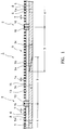
- Figs. 1 to 7 show an embodiment of the well screen according to the invention.
- the outer diameter equalizing means is constructed as a screen jacket which is made of two screen portions each of which includes a plurality of support rods and a wire wound on the outer periphery of the support rods.
- a well screen 1 is made of a plurality of screen units 2 connected in series.
- Each of the screen units 2 has connecting sections 3 provided at both ends and a screen section 4 between the connecting sections 3.
- the screen section 4 of each screen unit 2 includes a pipe 5 formed with fluid intake perforations 5a at a predetermined interval, support rods 6 extending in the axial direction of the screen 1 disposed cylindrically at a predetermined interval in the circumferential direction of the screen 1 and a wire 8 such as a wedge wire wound on the outer periphery of the support rods 6 so as to form slits 7 of a predetermined width.
- the support rods 6 are made of plate-like members which have a predetermined height in the radial direction of the screen 1 and have a substantially triangular cross section at one end.
- the wire 8 is welded to the support rods 6 at respective crossing points between the wire 8 and the support rods 6.
- the connecting section 4 is formed by extending the pipe 5 of the screen section 4 with its diameter being maintained unchanged.
- a male screw 3a is formed on one connecting section 3 of one of the screen units 2 and a female screw 3b is formed on the other connecting section 3 of the screen unit 2.
- the male screw 3a and the female screw 3b of opposite connecting sections of two adjacent screen units 2 are threaded together to connect the screen units 2.
- the connecting section 3 is formed with perforations 3c to allow flow of fluid between the outside and the inside of the screen unit 2 through the slits 14 of the wire 15 in the connecting section 3.
- the upper connecting section 3 of a preceding screen unit 2 which is suspended in the wellbore is threaded with the lower connecting section of a following screen unit 2.
- the screen portions 9a, 9b of the screen jacket 9 are mounted on the connecting sections 3 and the screen portions 9a and 9b are welded together at the straight frames 11.
- the screen portions 9a, 9b are also welded at the semi-circular flanges 10 to flanges 16 of adjacent screen sections 4 to seal the screen jacket 9 against invasion of sands from outside.
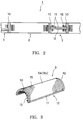
- Fig. 4 shows another example of connecting two screen portions of the screen jacket 9.
- two screen portions 9a, 9b are connected to each other by means of a hinge 17 at one end in the circumferential direction so that the two screen portions 9a, 9b are openable from a closed state.
- the same components as those in Fig. 1 are designated by the same reference characters and description thereof will be omitted.
- the two screen portions 9a, 9b may be connected to each other by means of bolts and nuts at the straight frame bars 11.
- Fig. 5 shows another example of sealing of the screen jacket 9 mounted on the connecting section 3.
- a small gap is provided between the flanges 10 of the screen portions 9a, 9b of the screen jacket 9 and the flanges 16 of the screen sections 4 and a seal member 18 made of rubber, sealant or the like material is filled in this gap to seal the screen jacket 9 from the outside.
- Fig. 6 shows another example of sealing of the screen jacket 9 mounted on the connecting section 3.
- the flanges 10 of the screen portions 9a, 9b are in abutting engagement with the flanges 16 of the screen sections 4 and the flanges 10 and 16 which are thus in abutting engagement with each other are bound by annular steel bands 19 which is fastened tightly about the flanges 10 and 16 by means of an unillustrated fastening means to provide a seal of the screen jacket 4 from the outside.
- the support rods and the wire wound about these support rods in the connecting section of the screen unit are constructed in the form of the screen jacket consisting of plural screen portions divided circumferentially.
- these support rods and the wire in the connecting section may be constructed as a single cylindrical screen jacket which is not divided circumferentially in plural portions and this screen jacket may be slipped on the connecting sections of two adjacent screen units.
- a gap produced between the screen jacket and the adjacent screen units should desirably be sealed by means of O-rings or other sealing means.
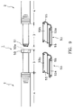
- Fig. 8 shows another embodiment of the well screen made according to the invention.
- support rods 36 and a wire 38 provided in a connecting section 33 of an upper screen unit 30 are formed by extending support rods 36 and a wire 38 wound thereon in a portion other than the connecting section 33, that is, a screen section 34 integrally and continuously over the outer periphery of the connecting section 33 to the end of the connecting section 33.
- the screen unit 30 of which one end has the above described structure has, at the other end, no support rods or screen wire in a connecting section 31 adjacent to the screen section 34 and has no fluid intake perforations as shown in a lower screen unit 30 of Fig. 8.
- This connecting section 31 is formed with a diametrically opposed pair of perforations 31b for inserting a support member 40 therethrough for suspending the screen unit 30 from the peripheral edge portion of the wellhead.
- the support member 40 is previously inserted through the perforations 31b of the connecting section 31 of the lower screen unit 30 and this screen unit 30 is suspended in the wellbore with the support member 40 crossing the wellbore and supported at the peripheral edge of the wellhead.
- a male screw 33a of the upper screen unit 30 is threaded with a female screw 31a of the lower screen unit 30 until a flange 37 of the upper screen unit 30 is lowered to a position shown by a dotted line in the figure.
- the support member 40 is pulled off the perforations 31b and a gap between flanges 37 and 38 including the perforations 31b is sealed by means of a sealant or the like material.
- Figs. 9 to 12 show another embodiment of the invention.
- the outer diameter equalizing means consists of a cylindrical cover plate which is composed of portions having a form obtained by dividing a cylinder in the circumferential direction.
- the cover plate has an outer diameter which is substantially equal to the outer diameter of a screen portion other than the connecting section.
- the same components as those in the embodiment of Figs. 1 to 8 are designated by the same reference characters and description thereof is omitted.
- annular coupling 50 for enlarging the diameter is mounted on one end of a connecting section of a lower screen unit 2.
- the coupling 50 is formed with a female screw 50a on the inner peripheral surface thereof.
- a connecting portion 3 of an upper screen unit 2 is formed with a male screw 51 which can be threaded with the female screw 50a.
- Cylindrical cover plates 53, 53 each of which is made of two plate portions 53a, 53a of a semi-circular cross section which are hingedly connected to each other by means of a hinge 54 are disposed about the mutually connected connecting sections 3, 3 of the upper and lower screen units 2, 2 so as to embrace the connecting sections 3, 3.
- Each of the cover plates 53, 53 is formed at end portions thereof with screw insertion holes 55 and a pipe 5 in the connecting sections 3, 3 is formed at corresponding positions with screw holes 56 (Fig. 12).
- the manner of fixing the cylindrical cover plates 53 is not limited to the above described manner but various other means including those used for fixing the screen jacket in the embodiment of Figs. 1 to 7 may be employed.
- cylindrical cover plates 60, 61 which constitute the outer diameter equalizing means are welded to end portions of support rods 6 to embrace connecting sections 3, 3 of adjacent screen units 2, 2.
- the cover plates 60, 61 are disposed at such location that, when the connecting sections 3, 3 are connected to each other, a part of the outer peripheral surface of the cover plate 60 is in contact with a part of the inner peripheral surface of the cover plate 61.
- one connecting section 3 is rotated for threaded engagement with the other connecting section 3
- one of the cover plates 60, 61 of the rotating connecting section 3 comes into engagement with the other to achieve the structure in which the outer surfaces of the adjacent screen units 2, 2 become flush with respect to each other as shown in Fig. 16.
- cover plates 60, 61 may be replaced by cylindrical screens and the connecting sections 3, 3 may be formed with fluid intake perforations.
- the inner peripheral surface of the cover plate 61 and the outer peripheral surface of the cover plate 60 need not necessarily be in contact with each other but there may be formed a gap between these surfaces.
- This invention is applicable to the well screens having a perforated pipe base as described above and also to a selective isolation type screen disclosed in U.S. Patent No. 4,771,829.
- a spiral wire or a plurality of rings arranged with a predetermined interval in the axial direction of the screen as disclosed in U.S. Patent No. 4,657,079 may be used.
- This invention is also applicable to all types of well screens including a well screen having shunt tubes as disclosed in U.S. Patent No. 4,945,991 and a dual cylinder screen as disclosed in Japanese Patent Application Laid-open No. Hei-5-44386.
Abstract
Description
- This invention relates generally to the field of oil well, gas well, water well and subterranean pollution remediation well equipment.
- Many types of screens and filtering devices are known in the art that are designed to exclude sand and other solids from fluids and gases produced from oil gas, water and pollution remediation wells without undue restriction of the production rate of fluids or gases. These devices are often used with filter aids, such as gravel and/or sand, which are either incorporated within the device or separately placed surrounding the device.
- Wire wrapped screens and prepacked screens are examples of devices used inside a drilled hole. The drilled hole may be left open or may have a casing or liner cemented and perforated prior to positioning such a device. Openings in such screens may be designed to stop, or bridge undesirable solids contained in fluids or gases.
- Screens and well liners are often surrounded by filter aids. The filter aids consist commonly of gravel. When used with filter aids or gravel, the openings in the screens and liners are designed to stop, or bridge, the filter aid and the filter aid is designed to stop or bridge the undesirable solids contained in the produced fluids or gases.
- Prepacked screens, porous material filter devices and such are examples of devices that incorporate a filter medial in the screen body. These devices are used for the same purpose and these filter aids commonly consist of gravel.
- Multiple wrapped screens provide two or more concentric wire wrappings which act as multiple filters in one device to prevent invention of undesirable solids and are often used with filter aids, such as gravel, in the well bore.
- As shown in Fig. 13, screen units of conventional well screens usually consist of lengths (joints) of from 5 to 10 meters with short lengths of blank (non-screen) pipe at each end. The purposes of the short length of blank pipe at each end. The purposes of the short lengths of blank pipe at each end are (1) to provide a means of connecting the joints together at a well site and (2) to facilitate holding each screen joint in a well-head as the joints are assembled for lowering into the well.
- The length of blank sections at the ends of each joint of screen must be long enough to allow for threads required for connecting the joints, and must be long enough to allow room to hang each joint in the well-head while joints are connected together. The total blank length is commonly 0.5 to 1 meter, after two joints have been connected together.
- A screen consisting of screen units which are connected together is commonly lowered, and centrallized, in a well bore to a position adjacent to a fluid or gas productive subterranian formation, wherefrom the fluid or gas can flow radially through the screen. The screen prevents entrance of undesirable solid particles and allows flow of fluid or gas inside the screen to be produced to the surface.
- For improving efficiency of production of oil from an oil well, there is an increasing tendency to producing oil from high angle well which is deviating from the vertical by 45 degrees to 90 degrees plus by passing a well screen into this high angle well.
- A problem which arises from the conventional type of well screen installed in such a high angle well is that, in inserting a screen in a wellbore, the screen is not centrallized as in the case of a screen in a vertical wellbore but the screen is inserted with a side thereof coming into contact with the bottom surface of the wellbore. Therefore, as shown in Fig. 14 which shows a wellbore extending horizontally, the foremost lower edge portion of a screen portion d of a screen s which advances in the direction X in a wellbore w and the foremost lower edge portion of a threaded coupling e of a blank portion b scrape up earth g of a bottom surface f of the wellbore w, and this earth g is heaped up in front of the lower edge portion of the screen portion d and the coupling e of the blank portion b and thereby prevents the advancement of the screen s in the direction X.
- Another problem arising from a high angle wellbore is that gravel is not packed uniformly due to existence of the blank portion in the screen.
- Gravel is normally packed most tightly in a location in an annulus between the screen and the wellbore where fluid carring the gravel circulates through the screen. Therefore, gravel cannot be packed so tightly in an annulus about the blank portion as in an annulus about the screen portion. In a vertical wellbore, gravel can be packed to some degree about the blank portion due to gravity but, in a high angle wellbore, as shown in Fig. 15, gravel h moves toward the bottom side of a wellbore w due to gravity and cannot be packed in a space about a blank portion b, so that a space i which is not packed with gravel is generated in the vicinity of the blank portion b.
- Gravel in the screen/wellbore annulus can then shift and slump after the well is put on production and this can form voids or unpacked annulus areas. Annulus areas where gravel is not tightly packed form paths for undesirable sand or solids from an unconsolidated sand formation to enter the wellbore and erode the screen, clog the screen openings, and/or to fill the inside of the wellbore with unwanted solids.
- U.S. Patent No. 4,945,991, Jones, L.G., "Methods for Gravel Packing Wells" discloses a screen with substantially rectangular perforated shunt tubes attached to the outside of a screen longitudinally over the entire length of the screen, and connected between all sectional lengths of screens attached together to provide flow paths for the gravel laden fluid to flow into and pack voids or unpacked areas of the screen/wellbore annulus. This device allows the gravel/fluid slurry to enter and flow through multiple flow paths near or above the screen and to thereafter flow both down the screen/wellbore annulus or down one or more of the appendaged perforated shunt tubes. Dehydration of the slurry in the perforated shunt tubes is inhibited by combination of limited area of perforations in the tubes and by the flow of gravel slurry down the screen/wellbore annulus, thus gravel slurry in the perforated shunt tubes is much less likely to be dehydrated and is most likely to flow continuously through the shunt tubes until it reaches the vicinity of a portion of the screen/wellbore annulus that is void of gravel or is not fully packed with gravel, then the gravel slurry in the perforated shunt tubes will flow into the inadequately gravel packed annulus.
- A problem with the device of U.S. Patent No. 4,945,991 is that the blank sections at the ends of each screen section has no screen through which fluid can flow during gravel packing or after the well is put on production.
- It is, therefore, a first object of the invention to provide an improved well screen suitable for use in a high angle wellbore which is capable of preventing earth from being heaped up in front of a connecting section of the screen by scraping of earth of the bottom surface of the wellbore by the lower edge portion of the advancing screen.
- It is a second object of the invention to provide a well screen which enables packing of gravel efficiently in the entire annulus between the screen and the wellbore.
- For achieving these objects of the invention, in a well screen composed of a plurality of screen units connected in series, each of said screen units having a cylindrical connecting section at least at one end thereof and including a plurality of support members extending in the axial direction of the screen disposed cylindrically about a section of the screen other than the connecting section at a predetermined interval in the circumferential direction of the screen, and wire means wound on the outer periphery of said support members so as to form slits of a predetermined width, the improvement comprises outer diameter equalizing means provided about adjacent ones of the connecting sections of two of the screen units connected to each other for substantially equalizing the outer diameter of said connecting sections to the outer diameter of sections other than the connecting sections.
- In the claims and specification of this application, the term "connecting section" means a threaded tube section provided at an end of each screen unit for connection with an adjacent screen unit and a blank section adjacent to this threaded tube section which has been provided in the screen unit of the conventional well screen for hanging the screen unit at the well head.
- According to the invention, by providing the outer diameter equalizing means about adjacent ones of the connecting sections of two of the screen units connected to each other for substantially equalizing the outer diameter of the connecting sections to the outer diameter of sections other than the connecting sections, the surfaces of the adjacent screen units become continuously flush with each other without producing any step in the connecting sections. Accordingly, in inserting the screen into a high angle wellbore, the foremost lower edge portion of each screen unit of the advancing screen does not scrape up the earth of the bottom surface of the wellbore and, therefore, heaping of earth in front of the connecting section of the screen unit can be effectively prevented.
- In one aspect of the invention, the outer diameter equalizing means comprises a plurality of support members extending in the axial direction of screen disposed cylindrically at a predetermined interval in the circumferential direction of the screen about at least said one conecting section of at least one of the screen units, and wire means wound on the outer periphery of said support members so as to form slits of a predetermined width, said connecting section being formed with openings which allow flow of fluid between the inside and the outside of said screen unit through the slits of said wire means.
- According to this aspect of the invention, since fluid flows from the outside of the screen to the inside thereof through the screen composed of the support members and wire means provided about the connecting section of each screen unit and the openings formed in the connecting section, this enables intake of fluid from the connecting section of the screen unit which has not been used for intake of fluid in the conventional well screen. As a result, potential production efficiency of the screen increases and hence the efficiency of fluid production from the well is improved.
- Embodiments of the invention will be described below with reference to the accompanying drawings.
- In the drawings,
- Fig. 1 is a partial sectional view of an embodiment of a screen made according to the invention;
- Fig. 2 is a side view of a part of this embodiment;
- Fig. 3 is a perspective view showing a part of a screen jacket disposed at the connecting section;
- Fig. 4 is a perspective view showing two screen sections of a screen jacket being hingedly connected to each other;
- Fig. 5 is a partial sectional view showing another example of connection of the screen jacket;
- Fig. 6 is a partial sectional view showing another example of connection of the screen jacket;
- Fig. 7 is a perspective view showing an arrangement of wires and support rods;
- Fig. 8 is a partial sectional view showing another embodiment of the invention;
- Fig. 9 is a view schematically showing another embodiment of the invention;
- Fig. 10 is a perspective view showing a cover plate of this embodiment;
- Fig. 11 is a side view showing mounting of the cover plates on the connecting sections;
- Fig. 12 is a partial sectional view showing the connecting section of this embodiment;
- Fig. 13 is a side view showing a prior art well screen:
- Fig. 14 is a view showing the state of advancing of a prior art screen through a high angle wellbore;
- Fig. 15 is a view showing a state of packing of gravel about a prior art screen in a high angle wellbore; and
- Fig. 16 is a partial sectional view showing another embodiment of the invention.
- Figs. 1 to 7 show an embodiment of the well screen according to the invention. In this embodiment, the outer diameter equalizing means is constructed as a screen jacket which is made of two screen portions each of which includes a plurality of support rods and a wire wound on the outer periphery of the support rods.
- A well
screen 1 is made of a plurality ofscreen units 2 connected in series. Each of thescreen units 2 has connectingsections 3 provided at both ends and ascreen section 4 between the connectingsections 3. - In the present embodiment, the
screen section 4 of eachscreen unit 2 includes apipe 5 formed withfluid intake perforations 5a at a predetermined interval,support rods 6 extending in the axial direction of thescreen 1 disposed cylindrically at a predetermined interval in the circumferential direction of thescreen 1 and awire 8 such as a wedge wire wound on the outer periphery of thesupport rods 6 so as to formslits 7 of a predetermined width. - As shown in Fig. 7, the
support rods 6 are made of plate-like members which have a predetermined height in the radial direction of thescreen 1 and have a substantially triangular cross section at one end. Thewire 8 is welded to thesupport rods 6 at respective crossing points between thewire 8 and thesupport rods 6. - In the present embodiment, the connecting
section 4 is formed by extending thepipe 5 of thescreen section 4 with its diameter being maintained unchanged. Amale screw 3a is formed on one connectingsection 3 of one of thescreen units 2 and afemale screw 3b is formed on the other connectingsection 3 of thescreen unit 2. Themale screw 3a and thefemale screw 3b of opposite connecting sections of twoadjacent screen units 2 are threaded together to connect thescreen units 2. - A
screen jacket 9 consisting of twoscreen portions sections 3. Each of thesescreen portions frame 12 consisting ofsemi-circular flanges screen portion 9a (9b) in the axial direction and straight frame bars 11, 11 provided at both ends of thescreen portion 9a (9b) in the circumferential direction,support rods 13 welded to thisframe 12, extending in the axial direction and disposed at predetermined interval in the circumferential direction, and awire 15 wound on the outer periphery of thesupport rods 13 to formslits 14 of a predetermined width. - The connecting
section 3 is formed withperforations 3c to allow flow of fluid between the outside and the inside of thescreen unit 2 through theslits 14 of thewire 15 in the connectingsection 3. - For installing this
screen 1, the upper connectingsection 3 of apreceding screen unit 2 which is suspended in the wellbore is threaded with the lower connecting section of a followingscreen unit 2. Then, thescreen portions screen jacket 9 are mounted on the connectingsections 3 and thescreen portions screen portions semi-circular flanges 10 toflanges 16 ofadjacent screen sections 4 to seal thescreen jacket 9 against invasion of sands from outside. Fig. 4 shows another example of connecting two screen portions of thescreen jacket 9. In this example, twoscreen portions hinge 17 at one end in the circumferential direction so that the twoscreen portions - Alternatively, the two
screen portions - Fig. 5 shows another example of sealing of the
screen jacket 9 mounted on the connectingsection 3. In this example, a small gap is provided between theflanges 10 of thescreen portions screen jacket 9 and theflanges 16 of thescreen sections 4 and aseal member 18 made of rubber, sealant or the like material is filled in this gap to seal thescreen jacket 9 from the outside. - Fig. 6 shows another example of sealing of the
screen jacket 9 mounted on the connectingsection 3. In this example, theflanges 10 of thescreen portions flanges 16 of thescreen sections 4 and theflanges annular steel bands 19 which is fastened tightly about theflanges screen jacket 4 from the outside. - In the embodiments shown in Figs. 1 to 7, the support rods and the wire wound about these support rods in the connecting section of the screen unit are constructed in the form of the screen jacket consisting of plural screen portions divided circumferentially. Alternatively, these support rods and the wire in the connecting section may be constructed as a single cylindrical screen jacket which is not divided circumferentially in plural portions and this screen jacket may be slipped on the connecting sections of two adjacent screen units. In this case also, a gap produced between the screen jacket and the adjacent screen units should desirably be sealed by means of O-rings or other sealing means.
- Fig. 8 shows another embodiment of the well screen made according to the invention.
- In this embodiment,
support rods 36 and awire 38 provided in a connectingsection 33 of anupper screen unit 30 are formed by extendingsupport rods 36 and awire 38 wound thereon in a portion other than the connectingsection 33, that is, ascreen section 34 integrally and continuously over the outer periphery of the connectingsection 33 to the end of the connectingsection 33. - A
pipe 5 in the connectingsection 33 is formed withfluid intake perforations 33c. - The
screen unit 30 of which one end has the above described structure has, at the other end, no support rods or screen wire in a connectingsection 31 adjacent to thescreen section 34 and has no fluid intake perforations as shown in alower screen unit 30 of Fig. 8. - This connecting
section 31 is formed with a diametrically opposed pair ofperforations 31b for inserting asupport member 40 therethrough for suspending thescreen unit 30 from the peripheral edge portion of the wellhead. - For installing this well screen, as shown in Fig. 8, the
support member 40 is previously inserted through theperforations 31b of the connectingsection 31 of thelower screen unit 30 and thisscreen unit 30 is suspended in the wellbore with thesupport member 40 crossing the wellbore and supported at the peripheral edge of the wellhead. - Then, a
male screw 33a of theupper screen unit 30 is threaded with afemale screw 31a of thelower screen unit 30 until aflange 37 of theupper screen unit 30 is lowered to a position shown by a dotted line in the figure. Then thesupport member 40 is pulled off theperforations 31b and a gap betweenflanges perforations 31b is sealed by means of a sealant or the like material. - Figs. 9 to 12 show another embodiment of the invention. In this embodiment, the outer diameter equalizing means consists of a cylindrical cover plate which is composed of portions having a form obtained by dividing a cylinder in the circumferential direction. The cover plate has an outer diameter which is substantially equal to the outer diameter of a screen portion other than the connecting section. In the embodiment of Figs. 9 to 12, the same components as those in the embodiment of Figs. 1 to 8 are designated by the same reference characters and description thereof is omitted.
- In this embodiment, an
annular coupling 50 for enlarging the diameter is mounted on one end of a connecting section of alower screen unit 2. Thecoupling 50 is formed with afemale screw 50a on the inner peripheral surface thereof. A connectingportion 3 of anupper screen unit 2 is formed with amale screw 51 which can be threaded with thefemale screw 50a. -
Cylindrical cover plates plate portions hinge 54 are disposed about the mutually connected connectingsections lower screen units sections cover plates pipe 5 in the connectingsections cylindrical cover plates sections cover plates pipe 5 in the connectingsections - The manner of fixing the
cylindrical cover plates 53 is not limited to the above described manner but various other means including those used for fixing the screen jacket in the embodiment of Figs. 1 to 7 may be employed. - Fig. 16 shows a still another embodiment of the invention. In this embodiment, the same components as those in the embodiment of Figs. 1 to 7 are designated by the same reference characters and description thereof is omitted.
- In this embodiment,
cylindrical cover plates support rods 6 to embrace connectingsections adjacent screen units cover plates sections cover plate 60 is in contact with a part of the inner peripheral surface of thecover plate 61. In this embodiment, when one connectingsection 3 is rotated for threaded engagement with the other connectingsection 3, one of thecover plates section 3 comes into engagement with the other to achieve the structure in which the outer surfaces of theadjacent screen units cover plates sections cover plate 61 and the outer peripheral surface of thecover plate 60 need not necessarily be in contact with each other but there may be formed a gap between these surfaces. - This invention is applicable to the well screens having a perforated pipe base as described above and also to a selective isolation type screen disclosed in U.S. Patent No. 4,771,829. As the base of the well screen, not only a perforated pipe, a spiral wire or a plurality of rings arranged with a predetermined interval in the axial direction of the screen as disclosed in U.S. Patent No. 4,657,079 may be used. This invention is also applicable to all types of well screens including a well screen having shunt tubes as disclosed in U.S. Patent No. 4,945,991 and a dual cylinder screen as disclosed in Japanese Patent Application Laid-open No. Hei-5-44386.
Claims (16)
- In a well screen composed of a plurality of screen units connected in series, each of said screen units having a cylindrical connecting section at least at one end thereof and including a plurality of support members extending in the axial direction of the screen disposed cylindrically about a section of the screen other than the connecting section at a predetermined interval in the circumferential direction of the screen, and wire means wound on the outer periphery of said support members so as to form slits of a predetermined width, the improvement comprising outer diameter equalizing means provided about adjacent ones of the connecting sections of two of the screen units connected to each other for substantially equalizing the outer diameter of said connecting sections to the outer diameter of sections other than the connecting sections.
- A well screen as defined in claim 1 wherein said outer diameter equalizing means comprises:
a plurality of support members extending in the axial direction of screen disposed cylindrically at a predetermined interval in the circumferential direction of the screen about at least said one connecting section of at least one of the screen units; and
wire means wound on the outer periphery of said support members so as to form slits of a predetermined width,
said connecting section being formed with openings which allow flow of fluid between the inside and the outside of said screen unit through the slits of said wire means. - A well screen as defined in claim 2 wherein said support members disposed in the connecting section and said wire means wound on the outer periphery of said support members are constructed as a screen jacket consisting of screen portions obtained by dividing a cylindrical screen in the circumferential direction, said screen portions being connected to each other.
- A well screen as defined in claim 3 wherein the screen portions of the screen jacket are hingedly connected to each other.
- A well screen as defined in claim 3 wherein the screen portions of the screen jacket are welded to each other.
- A well screen as defined in claim 3 wherein the screen portions of the screen jacket are connected to each other by means of bolts.
- A well screen as defined in claim 3 wherein the screen portions of the screen jacket are connected to each other by binding them by a belt.
- A well screen as defined in claim 2 wherein said support members disposed in the connecting section and said wire means wound on the outer periphery of said support members are formed by extending integrally and continuously support members disposed in the section of the screen other than the connecting section and the wire means wound on the outer periphery thereof to the outer periphery of said connecting section.
- A well screen as defined in claim 8 wherein a connecting section of an adjacent screen unit to which said connecting section in which said support members and said wire means are formed by extending the support members and wire means of the section of the screen other than the connecting section has a portion in which support members and wire means do not exist and which is formed with a pair of diametrically opposed perforations for inserting a support member used for suspending the adjacent screen unit at a peripheral edge portion of a wellhead.
- A well screen as defined in claim 1 wherein said outer diameter equalizing means comprises a cylindrical cover plate which consists of portions obtained by a cylinder in the circumferential direction, the outer diameter of said cover plate being substantially equal to the outer diameter of the section of the screen unit other than the connecting section.
- A well screen as defined in claim 10 wherein the portions of the cover plate are hingedly connected to each other.
- A well screen as defined in claim 10 wherein the portions of the cover plate are welded to each other.
- A well screen as defined in claim 10 wherein the portions of the cover plate are connected to each other by means of bolts.
- A well screen as defined in claim 10 wherein the portions of the cover plate are connected to each other by binding them by a belt.
- A well screen as defined in claim 1 wherein said outer diameter equalizing means comprises a pair of cylindrical cover plates fixed to end portions of two adjacent screen units, one of said cover plates being disposed at such a location that, when said connecting sections are connected to each other, one of said cover plates is partially located inside of the other cover plate.
- A well screen as defined in claim 1 wherein said outer diameter equalizing means comprises a pair of cylindrical screens fixed to end portions of two adjacent screen units, said cylindrical screens being disposed at such a location that, when said connecting sections are connected to each other, one of said cylindrical screens is partially located inside of the other cylindrical screen.
Applications Claiming Priority (3)
| Application Number | Priority Date | Filing Date | Title |
|---|---|---|---|
| JP5338870A JPH07158124A (en) | 1993-12-02 | 1993-12-02 | Screen for well having uniform outside diameter |
| JP338870/93 | 1993-12-02 | ||
| JP33887093 | 1993-12-02 |
Publications (3)
| Publication Number | Publication Date |
|---|---|
| EP0659975A2 true EP0659975A2 (en) | 1995-06-28 |
| EP0659975A3 EP0659975A3 (en) | 1997-03-12 |
| EP0659975B1 EP0659975B1 (en) | 2001-05-30 |
Family
ID=18322172
Family Applications (1)
| Application Number | Title | Priority Date | Filing Date |
|---|---|---|---|
| EP94118818A Expired - Lifetime EP0659975B1 (en) | 1993-12-02 | 1994-11-30 | Well screen having a uniform outer diameter |
Country Status (9)
| Country | Link |
|---|---|
| US (1) | US5787980A (en) |
| EP (1) | EP0659975B1 (en) |
| JP (1) | JPH07158124A (en) |
| CN (1) | CN1109548A (en) |
| AU (1) | AU7906994A (en) |
| BR (1) | BR9404805A (en) |
| CA (1) | CA2136694A1 (en) |
| DE (1) | DE69427338T2 (en) |
| RU (1) | RU94042229A (en) |
Cited By (15)
| Publication number | Priority date | Publication date | Assignee | Title |
|---|---|---|---|---|
| WO2000008301A2 (en) * | 1998-08-08 | 2000-02-17 | Weatherford/Lamb, Inc. | Connector for expandable well screen |
| US6527047B1 (en) | 1998-08-24 | 2003-03-04 | Weatherford/Lamb, Inc. | Method and apparatus for connecting tubulars using a top drive |
| US6622796B1 (en) | 1998-12-24 | 2003-09-23 | Weatherford/Lamb, Inc. | Apparatus and method for facilitating the connection of tubulars using a top drive |
| WO2003091536A1 (en) * | 2002-04-26 | 2003-11-06 | Tadayoshi Nagaoka | Cylindrical well screen having longitudinal skid rods |
| US6705405B1 (en) | 1998-08-24 | 2004-03-16 | Weatherford/Lamb, Inc. | Apparatus and method for connecting tubulars using a top drive |
| US6725938B1 (en) | 1998-12-24 | 2004-04-27 | Weatherford/Lamb, Inc. | Apparatus and method for facilitating the connection of tubulars using a top drive |
| US6742596B2 (en) | 2001-05-17 | 2004-06-01 | Weatherford/Lamb, Inc. | Apparatus and methods for tubular makeup interlock |
| US6976298B1 (en) | 1998-08-24 | 2005-12-20 | Weatherford/Lamb, Inc. | Methods and apparatus for connecting tubulars using a top drive |
| US6981547B2 (en) | 2002-12-06 | 2006-01-03 | Weatherford/Lamb, Inc. | Wire lock expandable connection |
| US7025135B2 (en) | 2003-05-22 | 2006-04-11 | Weatherford/Lamb, Inc. | Thread integrity feature for expandable connections |
| EP1690580A1 (en) * | 2005-02-14 | 2006-08-16 | TPR Fiberdur GmbH & Co. KG | Filter tube |
| US7107663B2 (en) | 2002-09-13 | 2006-09-19 | Weatherford/Lamb, Inc. | Expandable coupling |
| US7225523B2 (en) | 1997-03-21 | 2007-06-05 | Weatherford/Lamb, Inc. | Method for coupling and expanding tubing |
| US7240928B2 (en) | 2002-09-17 | 2007-07-10 | Weatherford/Lamb, Inc. | Tubing connection arrangement |
| ES2355673A1 (en) * | 2010-10-14 | 2011-03-30 | Fundacion Accion Contra El Hambre | Light structure for water wells. (Machine-translation by Google Translate, not legally binding) |
Families Citing this family (41)
| Publication number | Priority date | Publication date | Assignee | Title |
|---|---|---|---|---|
| US6536520B1 (en) | 2000-04-17 | 2003-03-25 | Weatherford/Lamb, Inc. | Top drive casing system |
| US6644406B1 (en) | 2000-07-31 | 2003-11-11 | Mobil Oil Corporation | Fracturing different levels within a completion interval of a well |
| US6464007B1 (en) | 2000-08-22 | 2002-10-15 | Exxonmobil Oil Corporation | Method and well tool for gravel packing a long well interval using low viscosity fluids |
| GB0021212D0 (en) | 2000-08-29 | 2000-10-18 | Kier Construction Ltd | Screen assembly for combined sewer overflow weir |
| GB2371319B (en) | 2001-01-23 | 2003-08-13 | Schlumberger Holdings | Completion Assemblies |
| US6644412B2 (en) * | 2001-04-25 | 2003-11-11 | Weatherford/Lamb, Inc. | Flow control apparatus for use in a wellbore |
| US6588506B2 (en) | 2001-05-25 | 2003-07-08 | Exxonmobil Corporation | Method and apparatus for gravel packing a well |
| GB0215668D0 (en) * | 2002-07-06 | 2002-08-14 | Weatherford Lamb | Coupling tubulars |
| US7730965B2 (en) | 2002-12-13 | 2010-06-08 | Weatherford/Lamb, Inc. | Retractable joint and cementing shoe for use in completing a wellbore |
| GB0222321D0 (en) * | 2002-09-25 | 2002-10-30 | Weatherford Lamb | Expandable connection |
| USRE42877E1 (en) | 2003-02-07 | 2011-11-01 | Weatherford/Lamb, Inc. | Methods and apparatus for wellbore construction and completion |
| US7870898B2 (en) * | 2003-03-31 | 2011-01-18 | Exxonmobil Upstream Research Company | Well flow control systems and methods |
| US7464752B2 (en) * | 2003-03-31 | 2008-12-16 | Exxonmobil Upstream Research Company | Wellbore apparatus and method for completion, production and injection |
| GB0311721D0 (en) * | 2003-05-22 | 2003-06-25 | Weatherford Lamb | Tubing connector |
| US7887103B2 (en) | 2003-05-22 | 2011-02-15 | Watherford/Lamb, Inc. | Energizing seal for expandable connections |
| US7650944B1 (en) | 2003-07-11 | 2010-01-26 | Weatherford/Lamb, Inc. | Vessel for well intervention |
| US7281319B1 (en) | 2004-04-30 | 2007-10-16 | Daniel Allford | Apparatus for manufacturing wire wound filter screens |
| WO2006063207A2 (en) * | 2004-12-09 | 2006-06-15 | Purolator Facet, Inc. | Unsintered mesh sand control screen |
| CA2538196C (en) | 2005-02-28 | 2011-10-11 | Weatherford/Lamb, Inc. | Deep water drilling with casing |
| EP2089579A1 (en) * | 2006-12-04 | 2009-08-19 | Pall Corporation | Filtering device, especially for use as a well screen filter |
| US8511380B2 (en) * | 2007-10-10 | 2013-08-20 | Schlumberger Technology Corporation | Multi-zone gravel pack system with pipe coupling and integrated valve |
| CA2742365C (en) * | 2008-11-03 | 2014-03-18 | Exxonmobil Upstream Research Company | Well flow control systems and methods |
| US20100122810A1 (en) * | 2008-11-19 | 2010-05-20 | Langlais Michael D | Well screens and method of making well screens |
| US8146662B2 (en) * | 2009-04-08 | 2012-04-03 | Halliburton Energy Services, Inc. | Well screen assembly with multi-gage wire wrapped layer |
| US20100258302A1 (en) * | 2009-04-08 | 2010-10-14 | Halliburton Energy Services, Inc. | Well Screen With Drainage Assembly |
| US8251138B2 (en) * | 2009-04-09 | 2012-08-28 | Halliburton Energy Services, Inc. | Securing layers in a well screen assembly |
| US8291971B2 (en) | 2010-08-13 | 2012-10-23 | Halliburton Energy Services, Inc. | Crimped end wrapped on pipe well screen |
| US9593559B2 (en) | 2011-10-12 | 2017-03-14 | Exxonmobil Upstream Research Company | Fluid filtering device for a wellbore and method for completing a wellbore |
| CN103084000A (en) * | 2011-11-08 | 2013-05-08 | 罗菁 | Combined tube well filter |
| JP5920562B2 (en) * | 2011-11-11 | 2016-05-18 | 株式会社ナガオカ | Intake well intake structure |
| US9010417B2 (en) | 2012-02-09 | 2015-04-21 | Baker Hughes Incorporated | Downhole screen with exterior bypass tubes and fluid interconnections at tubular joints therefore |
| US9725989B2 (en) | 2013-03-15 | 2017-08-08 | Exxonmobil Upstream Research Company | Sand control screen having improved reliability |
| WO2014149396A2 (en) | 2013-03-15 | 2014-09-25 | Exxonmobil Upstream Research Company | Apparatus and methods for well control |
| US9580999B2 (en) * | 2013-05-20 | 2017-02-28 | Halliburton Energy Services, Inc. | Gravel packing apparatus having a jumper tube protection assembly |
| US10145222B2 (en) | 2014-05-02 | 2018-12-04 | Superior Energy Services, Llc | Over-coupling screen communication system |
| US10358897B2 (en) | 2014-05-02 | 2019-07-23 | Superior Energy Services, Llc | Over-coupling screen communication system |
| MY188272A (en) * | 2014-09-16 | 2021-11-24 | Halliburton Energy Services Inc | Screened communication connector for a production tubing joint |
| US10358898B2 (en) * | 2015-02-13 | 2019-07-23 | Halliburton Energy Services, Inc. | Sand control screen assemblies with erosion-resistant flow paths |
| US9988884B2 (en) * | 2015-06-29 | 2018-06-05 | Baker Hughes, A Ge Company, Llc | Annular screen communication system |
| US10422203B2 (en) * | 2017-03-22 | 2019-09-24 | Baker Hughes, A Ge Company, Llc | Screen connection area assembly for gravel pack and method |
| EP3604734B1 (en) * | 2018-08-01 | 2021-10-20 | 3M Innovative Properties Company | Separating device and use of a separating device |
Citations (3)
| Publication number | Priority date | Publication date | Assignee | Title |
|---|---|---|---|---|
| US1367406A (en) * | 1920-03-01 | 1921-02-01 | Mclean Marrs | Well-screen |
| US4388968A (en) * | 1981-04-17 | 1983-06-21 | Halliburton Company | Downhole tool suction screen assembly |
| WO1993004257A2 (en) * | 1991-08-17 | 1993-03-04 | Gd-Anker Gmbh | Drilling pipe |
Family Cites Families (5)
| Publication number | Priority date | Publication date | Assignee | Title |
|---|---|---|---|---|
| US725117A (en) * | 1903-01-08 | 1903-04-14 | John Morris | Well-strainer. |
| US2353881A (en) * | 1942-12-07 | 1944-07-18 | Shell Dev | Oil well liner screen |
| JPS5832275B2 (en) * | 1980-12-11 | 1983-07-12 | 永岡金網株式会社 | screen |
| US4771829A (en) * | 1987-12-30 | 1988-09-20 | Sparlin Derry D | Well liner with selective isolation screen |
| US4945991A (en) * | 1989-08-23 | 1990-08-07 | Mobile Oil Corporation | Method for gravel packing wells |
-
1993
- 1993-12-02 JP JP5338870A patent/JPH07158124A/en not_active Withdrawn
-
1994
- 1994-11-25 CA CA002136694A patent/CA2136694A1/en not_active Abandoned
- 1994-11-28 AU AU79069/94A patent/AU7906994A/en not_active Abandoned
- 1994-11-28 US US08/345,613 patent/US5787980A/en not_active Expired - Fee Related
- 1994-11-30 DE DE69427338T patent/DE69427338T2/en not_active Expired - Fee Related
- 1994-11-30 EP EP94118818A patent/EP0659975B1/en not_active Expired - Lifetime
- 1994-12-01 RU RU94042229/03A patent/RU94042229A/en unknown
- 1994-12-01 CN CN94114083A patent/CN1109548A/en active Pending
- 1994-12-01 BR BR9404805A patent/BR9404805A/en not_active Application Discontinuation
Patent Citations (3)
| Publication number | Priority date | Publication date | Assignee | Title |
|---|---|---|---|---|
| US1367406A (en) * | 1920-03-01 | 1921-02-01 | Mclean Marrs | Well-screen |
| US4388968A (en) * | 1981-04-17 | 1983-06-21 | Halliburton Company | Downhole tool suction screen assembly |
| WO1993004257A2 (en) * | 1991-08-17 | 1993-03-04 | Gd-Anker Gmbh | Drilling pipe |
Cited By (21)
| Publication number | Priority date | Publication date | Assignee | Title |
|---|---|---|---|---|
| US7225523B2 (en) | 1997-03-21 | 2007-06-05 | Weatherford/Lamb, Inc. | Method for coupling and expanding tubing |
| US6722443B1 (en) | 1998-08-08 | 2004-04-20 | Weatherford/Lamb, Inc. | Connector for expandable well screen |
| WO2000008301A3 (en) * | 1998-08-08 | 2000-06-02 | Petroline Wellsystems Ltd | Connector for expandable well screen |
| US7140446B2 (en) | 1998-08-08 | 2006-11-28 | Weatherford/ Lamb, Inc. | Connector for expandable well screen |
| WO2000008301A2 (en) * | 1998-08-08 | 2000-02-17 | Weatherford/Lamb, Inc. | Connector for expandable well screen |
| US6896057B2 (en) | 1998-08-08 | 2005-05-24 | Weatherford/Lamb, Inc. | Connector for expandable well screen |
| US6976298B1 (en) | 1998-08-24 | 2005-12-20 | Weatherford/Lamb, Inc. | Methods and apparatus for connecting tubulars using a top drive |
| US6705405B1 (en) | 1998-08-24 | 2004-03-16 | Weatherford/Lamb, Inc. | Apparatus and method for connecting tubulars using a top drive |
| US6527047B1 (en) | 1998-08-24 | 2003-03-04 | Weatherford/Lamb, Inc. | Method and apparatus for connecting tubulars using a top drive |
| US7021374B2 (en) | 1998-08-24 | 2006-04-04 | Weatherford/Lamb, Inc. | Method and apparatus for connecting tubulars using a top drive |
| US6622796B1 (en) | 1998-12-24 | 2003-09-23 | Weatherford/Lamb, Inc. | Apparatus and method for facilitating the connection of tubulars using a top drive |
| US6725938B1 (en) | 1998-12-24 | 2004-04-27 | Weatherford/Lamb, Inc. | Apparatus and method for facilitating the connection of tubulars using a top drive |
| US6742596B2 (en) | 2001-05-17 | 2004-06-01 | Weatherford/Lamb, Inc. | Apparatus and methods for tubular makeup interlock |
| WO2003091536A1 (en) * | 2002-04-26 | 2003-11-06 | Tadayoshi Nagaoka | Cylindrical well screen having longitudinal skid rods |
| US7107663B2 (en) | 2002-09-13 | 2006-09-19 | Weatherford/Lamb, Inc. | Expandable coupling |
| US7240928B2 (en) | 2002-09-17 | 2007-07-10 | Weatherford/Lamb, Inc. | Tubing connection arrangement |
| US8136216B2 (en) | 2002-09-17 | 2012-03-20 | Weatherford/Lamb, Inc. | Method of coupling expandable tubing sections |
| US6981547B2 (en) | 2002-12-06 | 2006-01-03 | Weatherford/Lamb, Inc. | Wire lock expandable connection |
| US7025135B2 (en) | 2003-05-22 | 2006-04-11 | Weatherford/Lamb, Inc. | Thread integrity feature for expandable connections |
| EP1690580A1 (en) * | 2005-02-14 | 2006-08-16 | TPR Fiberdur GmbH & Co. KG | Filter tube |
| ES2355673A1 (en) * | 2010-10-14 | 2011-03-30 | Fundacion Accion Contra El Hambre | Light structure for water wells. (Machine-translation by Google Translate, not legally binding) |
Also Published As
| Publication number | Publication date |
|---|---|
| AU7906994A (en) | 1995-06-08 |
| BR9404805A (en) | 1995-08-08 |
| EP0659975B1 (en) | 2001-05-30 |
| DE69427338T2 (en) | 2002-04-25 |
| CA2136694A1 (en) | 1995-06-03 |
| JPH07158124A (en) | 1995-06-20 |
| DE69427338D1 (en) | 2001-07-05 |
| CN1109548A (en) | 1995-10-04 |
| US5787980A (en) | 1998-08-04 |
| RU94042229A (en) | 1996-10-10 |
| EP0659975A3 (en) | 1997-03-12 |
Similar Documents
| Publication | Publication Date | Title |
|---|---|---|
| US5787980A (en) | Well screen having a uniform outer diameter | |
| US5476143A (en) | Well screen having slurry flow paths | |
| US5355948A (en) | Permeable isolation sectioned screen | |
| US5355949A (en) | Well liner with dual concentric half screens | |
| CA2366000C (en) | Well screen having an internal alternate flowpath | |
| US5004049A (en) | Low profile dual screen prepack | |
| RU2114285C1 (en) | Hole filter | |
| RU2079638C1 (en) | Well screen (versions) | |
| US10072482B2 (en) | Leak-off assembly for gravel pack system | |
| US6125932A (en) | Tortuous path sand control screen and method for use of same | |
| EP0634561A1 (en) | Sand screen for use in wells | |
| US5083614A (en) | Flexible gravel prepack production system for wells having high dog-leg severity | |
| BR112013003036B1 (en) | WELL SCREEN SET AND METHOD FOR BUILDING A WELL SCREEN | |
| CA2879153C (en) | Leak-off assembly for gravel pack system | |
| AU2004304246B2 (en) | Wellbore gravel packing apparatus and method | |
| EP3388618B1 (en) | Exterior drain tube for well screen assemblies | |
| RU2141028C1 (en) | Well strainer with alternative ways of flow | |
| MXPA06006226A (en) | Wellbore gravel packing apparatus and method |
Legal Events
| Date | Code | Title | Description |
|---|---|---|---|
| PUAI | Public reference made under article 153(3) epc to a published international application that has entered the european phase |
Free format text: ORIGINAL CODE: 0009012 |
|
| 17P | Request for examination filed |
Effective date: 19941130 |
|
| AK | Designated contracting states |
Kind code of ref document: A2 Designated state(s): CH DE FR GB LI NL |
|
| PUAL | Search report despatched |
Free format text: ORIGINAL CODE: 0009013 |
|
| AK | Designated contracting states |
Kind code of ref document: A3 Designated state(s): CH DE FR GB LI NL |
|
| 17Q | First examination report despatched |
Effective date: 19990415 |
|
| GRAG | Despatch of communication of intention to grant |
Free format text: ORIGINAL CODE: EPIDOS AGRA |
|
| GRAG | Despatch of communication of intention to grant |
Free format text: ORIGINAL CODE: EPIDOS AGRA |
|
| GRAH | Despatch of communication of intention to grant a patent |
Free format text: ORIGINAL CODE: EPIDOS IGRA |
|
| GRAH | Despatch of communication of intention to grant a patent |
Free format text: ORIGINAL CODE: EPIDOS IGRA |
|
| GRAA | (expected) grant |
Free format text: ORIGINAL CODE: 0009210 |
|
| AK | Designated contracting states |
Kind code of ref document: B1 Designated state(s): CH DE FR GB LI NL |
|
| REG | Reference to a national code |
Ref country code: CH Ref legal event code: EP |
|
| REF | Corresponds to: |
Ref document number: 69427338 Country of ref document: DE Date of ref document: 20010705 |
|
| ET | Fr: translation filed | ||
| REG | Reference to a national code |
Ref country code: CH Ref legal event code: NV Representative=s name: TROESCH SCHEIDEGGER WERNER AG |
|
| REG | Reference to a national code |
Ref country code: GB Ref legal event code: IF02 |
|
| PLBE | No opposition filed within time limit |
Free format text: ORIGINAL CODE: 0009261 |
|
| STAA | Information on the status of an ep patent application or granted ep patent |
Free format text: STATUS: NO OPPOSITION FILED WITHIN TIME LIMIT |
|
| 26N | No opposition filed | ||
| PGFP | Annual fee paid to national office [announced via postgrant information from national office to epo] |
Ref country code: NL Payment date: 20021118 Year of fee payment: 9 |
|
| PGFP | Annual fee paid to national office [announced via postgrant information from national office to epo] |
Ref country code: CH Payment date: 20021122 Year of fee payment: 9 |
|
| PGFP | Annual fee paid to national office [announced via postgrant information from national office to epo] |
Ref country code: DE Payment date: 20021223 Year of fee payment: 9 |
|
| PG25 | Lapsed in a contracting state [announced via postgrant information from national office to epo] |
Ref country code: LI Free format text: LAPSE BECAUSE OF NON-PAYMENT OF DUE FEES Effective date: 20031130 Ref country code: CH Free format text: LAPSE BECAUSE OF NON-PAYMENT OF DUE FEES Effective date: 20031130 |
|
| PG25 | Lapsed in a contracting state [announced via postgrant information from national office to epo] |
Ref country code: NL Free format text: LAPSE BECAUSE OF NON-PAYMENT OF DUE FEES Effective date: 20040601 |
|
| PG25 | Lapsed in a contracting state [announced via postgrant information from national office to epo] |
Ref country code: DE Free format text: LAPSE BECAUSE OF NON-PAYMENT OF DUE FEES Effective date: 20040602 |
|
| REG | Reference to a national code |
Ref country code: CH Ref legal event code: PL |
|
| NLV4 | Nl: lapsed or anulled due to non-payment of the annual fee |
Effective date: 20040601 |
|
| PGFP | Annual fee paid to national office [announced via postgrant information from national office to epo] |
Ref country code: GB Payment date: 20041221 Year of fee payment: 11 Ref country code: FR Payment date: 20041221 Year of fee payment: 11 |
|
| PG25 | Lapsed in a contracting state [announced via postgrant information from national office to epo] |
Ref country code: GB Free format text: LAPSE BECAUSE OF NON-PAYMENT OF DUE FEES Effective date: 20051130 |
|
| GBPC | Gb: european patent ceased through non-payment of renewal fee |
Effective date: 20051130 |
|
| PG25 | Lapsed in a contracting state [announced via postgrant information from national office to epo] |
Ref country code: FR Free format text: LAPSE BECAUSE OF NON-PAYMENT OF DUE FEES Effective date: 20060731 |
|
| REG | Reference to a national code |
Ref country code: FR Ref legal event code: ST Effective date: 20060731 |