EP0656262A1 - Tape cassette and tape printer for use therewith - Google Patents
Tape cassette and tape printer for use therewith Download PDFInfo
- Publication number
- EP0656262A1 EP0656262A1 EP95101056A EP95101056A EP0656262A1 EP 0656262 A1 EP0656262 A1 EP 0656262A1 EP 95101056 A EP95101056 A EP 95101056A EP 95101056 A EP95101056 A EP 95101056A EP 0656262 A1 EP0656262 A1 EP 0656262A1
- Authority
- EP
- European Patent Office
- Prior art keywords
- tape
- cassette
- printing
- printer
- platen
- Prior art date
- Legal status (The legal status is an assumption and is not a legal conclusion. Google has not performed a legal analysis and makes no representation as to the accuracy of the status listed.)
- Withdrawn
Links
Images


Classifications
-
- B—PERFORMING OPERATIONS; TRANSPORTING
- B41—PRINTING; LINING MACHINES; TYPEWRITERS; STAMPS
- B41J—TYPEWRITERS; SELECTIVE PRINTING MECHANISMS, i.e. MECHANISMS PRINTING OTHERWISE THAN FROM A FORME; CORRECTION OF TYPOGRAPHICAL ERRORS
- B41J11/00—Devices or arrangements of selective printing mechanisms, e.g. ink-jet printers or thermal printers, for supporting or handling copy material in sheet or web form
- B41J11/66—Applications of cutting devices
- B41J11/70—Applications of cutting devices cutting perpendicular to the direction of paper feed
- B41J11/703—Cutting of tape
-
- B—PERFORMING OPERATIONS; TRANSPORTING
- B41—PRINTING; LINING MACHINES; TYPEWRITERS; STAMPS
- B41J—TYPEWRITERS; SELECTIVE PRINTING MECHANISMS, i.e. MECHANISMS PRINTING OTHERWISE THAN FROM A FORME; CORRECTION OF TYPOGRAPHICAL ERRORS
- B41J15/00—Devices or arrangements of selective printing mechanisms, e.g. ink-jet printers or thermal printers, specially adapted for supporting or handling copy material in continuous form, e.g. webs
- B41J15/04—Supporting, feeding, or guiding devices; Mountings for web rolls or spindles
- B41J15/044—Cassettes or cartridges containing continuous copy material, tape, for setting into printing devices
-
- B—PERFORMING OPERATIONS; TRANSPORTING
- B41—PRINTING; LINING MACHINES; TYPEWRITERS; STAMPS
- B41J—TYPEWRITERS; SELECTIVE PRINTING MECHANISMS, i.e. MECHANISMS PRINTING OTHERWISE THAN FROM A FORME; CORRECTION OF TYPOGRAPHICAL ERRORS
- B41J25/00—Actions or mechanisms not otherwise provided for
- B41J25/304—Bodily-movable mechanisms for print heads or carriages movable towards or from paper surface
-
- B—PERFORMING OPERATIONS; TRANSPORTING
- B41—PRINTING; LINING MACHINES; TYPEWRITERS; STAMPS
- B41J—TYPEWRITERS; SELECTIVE PRINTING MECHANISMS, i.e. MECHANISMS PRINTING OTHERWISE THAN FROM A FORME; CORRECTION OF TYPOGRAPHICAL ERRORS
- B41J3/00—Typewriters or selective printing or marking mechanisms characterised by the purpose for which they are constructed
- B41J3/407—Typewriters or selective printing or marking mechanisms characterised by the purpose for which they are constructed for marking on special material
- B41J3/4075—Tape printers; Label printers
-
- B—PERFORMING OPERATIONS; TRANSPORTING
- B41—PRINTING; LINING MACHINES; TYPEWRITERS; STAMPS
- B41J—TYPEWRITERS; SELECTIVE PRINTING MECHANISMS, i.e. MECHANISMS PRINTING OTHERWISE THAN FROM A FORME; CORRECTION OF TYPOGRAPHICAL ERRORS
- B41J32/00—Ink-ribbon cartridges
Definitions
- This invention relates to a tape cassette provided with an image source tape such as ink ribbon and an image receiving tape and also to a tape printer for use with such a tape cassette, the tape printer having a printing head and a platen disposed in a face-to-face relation to each other such that the two tapes in the tape cassette are driven through a printing area between the printing head and platen for printing an image from the printing head onto the image receiving tape via the image source tape by, for instance, a thermal printing process or a thermal transfer process, the image receiving tape after the printing being used as label or the like.
- the printing is done on the non-adhesive surface of the single-side adhesive tape when obtaining a tape for general display or as a label. Therefore, after the tape is applied at an intended position or to an intended object by separating the separable sheet, the printed image is liable to become blurred by being touched by an object. To prevent this, it is necessary to cover the printing surface by applying a transparent sheet or the like thereto, which is cumbersome. Further, peel-off of the print is liable to result due to direct contact of the printing surface with a feed roller when the tape is fed out of the tape printer after printing.
- tape printer of the type described is mostly used to produce tapes for general display or serving as labels.
- the present invention has in the light of the above problems inherent in the prior art, as its object to provide a tape cassette, which is richly versatile and permits production of a tape for general display or serving as a label and with the printing surface protected to prevent direct contact while also permitting production of a tape (hereinafter referred to as a lettering tape) used to obtain an instant lettering image on a separate sheet by pushing the printing surface thereon, and also a tape printer, which is used with such a tape cassette, simple in construction and operation and inexpensive.
- a tape cassette which has a housing formed with first to third accommodation sections, the first and second accommodation sections respectively accommodating an image source tape and a substantially transparent image receiving tape, the third accommodation section accommodating an adhesive tape having an adhesive surface to be applied to the printing surface of the image receiving tape after printing thereon of an image.
- the printing surface is protected by the adhesive tape, so that the printed image will never be damaged with rubbing of the printing surface while or after the produced tape is fed out of the tape printer.
- a durable tape may be produced, which can be used for general display or as a label such that the printing surface of a transparent image receiving tape is seen from the back side opposite the printing surface.
- one of first and second feed roller means for feeding out the image receiving tape after printing together with the adhesive tape is disposed in the tape cassette, and with the loading of the tape cassette in the tape printer frame the other feed roller means provided in the tape printer frame is urged against the aforesaid one feed roller means so that the tapes are fed out in a state clamped between the two feed roller means.
- the first to third accommodation sections are juxtaposed side by side substantially in the same plane in the tape cassette housing, and the third accommodation section which accommodates the adhesive tape is disposed closer to the tape outlet than the other accommodation sections.
- the adhesive tape is a double-sided adhesive tape having one adhesive surface applied to the printing surface of the image receiving tape and the other adhesive surface, to which a separable sheet is applied.
- the produced tape may be applied after separation of the separable sheet at an intended position or to an intended object for general display or as a label such that the surface of the image receiving tape, which is transparent, opposite the printing surface is seen.
- a thermal transfer type image source tape and a thermal transfer type image receiving tape are accommodated in the respective first and second accommodation sections, while an adhesive tape is accommodated in the third accommodation section.
- a thermal transfer type image source tape and a thermal transfer type image receiving tape are accommodated in the respective first and second accommodation sections, while nothing is accommodated in the third accommodation section.
- tape production cassettes having different purposes can be constructed by using a common cassette housing, and a cassette housing which is rich in versatility can be provided.
- the tape printer of the present invention can be adopted to produce various tapes of the different purposes noted above in a mirror image transfer mode. That is, there is no cumbersomeness of transfer mode switching, and there is no need of providing a control mechanism to such an end.
- Figs. 1 and 2 show the overall structure of a tape printer as a first embodiment of the invention.
- the tape printer 1 has a frame 3, on top of which a rotary character selection dial 5 is provided.
- the character selection dial 5 has an annular shape, and on its annular dial surface 7 impressions of alphabet letters, symbols and other characters (hereinafter collectively referred to as characters) are provided at a uniform interval.
- a pointer 9 On top of the frame 3 is also provided adjacent to the character selection dial 5 a pointer 9 which determines a character selection position of the dial 5.
- a determination key 11 On the inner side of the dial 5, a determination key 11 is provided concentrically. By depressing the determination key 11 after manipulating the character selection dial 5 for character selection, a character at the position corresponding to the pointer 9 is determined as input character. Characters which are consecutively set to the position corresponding to the pointer are displayed in the same order on a liquid crystal display 13 on top of the frame 3 from the lowest place by a character selection mechanism and control means provided on top of the frame 3. Every time a character determination process is done by the determination key 11, the displayed characters are scrolled to higher places by one place. The input characters are consecutively stored in an internal memory.
- a print key 17 and a plurality of function keys 19 which are operable for controlling the tape printer 1.
- a label tape 21 is produced.
- the label tape 21 thus produced bears an impression or image of characters displayed on the liquid crystal display 13 and stored in the internal memory. It is fed out of the frame 3 through a tape outlet 23 provided on one side of the frame 3. It is cut to a suitable length, the cut tape being used for general display or applied for use as a label to a sheet or other object.
- Fig. 3 shows the structure of the label tape produced by the tape printer 1 in the manner as described above.
- the tape 21 consists of a transparent tape 25 as printing tape or image receiving tape and a double-sided adhesive tape 27 applied to the transparent tape 25.
- the double-sided adhesive tape 27 has a transparent base 27a with opposite side, i.e., first and second adhesive surfaces 27b and 27c and a separable sheet 27d applied to the second adhesive surface 27c.
- a character image impression 29 is formed by the tape printer 1 such that it is a positive image when viewed from the front surface side of the transparent tape 25.
- the back surface of the transparent tape 25 and the first adhesive surface 27b of the double-sided adhesive tape 27 are applied together. That is, the back surface of the tape 25 serves as the printing surface.
- the print image 29 thus is sandwiched between the transparent tape 25 and double-sided adhesive tape 27 and will never be contaminated or become blurred due to friction.
- the tape 21 is cut to a suitable length, and then by separating the separable sheet 27 it is applied to an intended sheet or other object by the adhesive force of the exposed second adhesive surface 27c.
- Fig. 2 shows the tape printer 1 viewed from the back side.
- the back side of the frame 3 is formed with a cassette accommodation recess 31, and a cassette cover 33 is mounted to close the opening of the recess 31.
- a release lever 34a is slidably provided on the frame 3.
- a platen holder 59 to be described later is raised by a mechanism 34 (Figs. 4 and 5) to bring thermal head 83 and platen 75 to their inoperative position.
- the mechanism 34 uses suitable cam means.
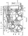
- Figs. 4 and 5 are sections taken in a plane through the tape outlet 23 of the frame 3 and also show part of the tape cassette 35 in a broken form.
- a side frame 37 is provided in the frame 3 adjacent to the tape outlet 23.
- the side frame 37 is formed adjacent to its lower end with a hole 39, in which is rotatably mounted a cam shaft 43 having a cam 41 provided at one end.
- a cutter lever 45 is secured to the other end of the cam shaft 43 extending outwardly from the frame 3.
- the side frame 37 is formed with two, vertically aligned, vertically elongated slots 47.
- a cutter holder 51 having a cutter 49 provided at the upper end is mounted on the side frame 37 by two flat screws 53 passed through the respective slots 47 such that it is vertically movable along the side frame 37 in a range corresponding to the vertical dimension of the slots 47.
- the cutter holder 51 is downwardly biased by a tension spring (not shown), and its downward movement is limited as its lower end strikes the cam 41 of the cam shaft 43.
- the cutter holder 51 is movable vertically as the position of contact between the cam 41 and its lower end is changed with the rotation of the cutter lever 45.
- a tape path 55, along which the label tape 21 is driven, is formed above the side frame 37 such that it extends to the tape outlet 23.
- a support shaft 57 is provided above the tape path 55.
- the platen holder 59 noted above is mounted on the support shaft 57 such that it is rotatable between a release or inoperative position as shown in Fig. 4 and a contact or operative position as shown in Fig. 5.
- the platen holder 59 is biased downwardly, i.e., toward the operative position, by the restoring force of a curved leaf spring 61 having one end secured to the side frame 37.
- Fig. 4 shows the platen holder 59 having been raised by the mechanism 34 against the biasing force of the leaf spring 61 caused by rightward movement of the release lever 34a as shown by arrow in Fig. 4.
- the platen holder 59 has a top portion 59a and a pair of depending portions 59b and 59c depending from the opposite sides of the top portion 59a.
- the depending portions 59b and 59c are each formed with a hole 63 receiving the support shaft 57 of the side frame 37, a hole 65 receiving a feed roller shaft and a vertically elongated hole 67 receiving a platen shaft 75b.
- a feed roller assembly 73 having a driven feed roller 69 and a driven gear 71 is rotatably mounted in the holes 65.
- the corresponding platen shafts 75b supporting the platen 75 such that it is capable of slight vertical movement in a range corresponding to the vertical dimension of the holes 67 relative to the platen holder 59.
- Opposed short pins 77 project from the respective opposed surfaces of free ends of the depending portions 59b and 59c of the platen holder 59.
- a platen bias spring 79 is mounted in the short pins 77.
- This platen bias spring 79 has two coil spring portions 79a connected to each other by a connecting portion 79b and arm portions 79c each extending from the free end of each coil spring portion 79a.
- the platen bias spring 79, holes 67 and platen shaft 75b constitute elastic biasing means for supporting the platen 75 such that it is slightly movable vertically with respect to the platen holder 75.
- the platen bias spring 79 is mounted such that the coil spring portions 79a are fitted on the short pins 77, that the connecting portion 79b is in contact with the underside of the top portion 59a of the platen holder 59 and that the arm portions 79c are engaged with shoulders 75a formed at the opposite ends of the platen 75.
- the platen 75 thus is biased downwardly with a predetermined spring force provided by the elastic restoring force of the coil spring portions 79a of the platen bias spring 79.
- the spring force, with which the platen bias spring 79 biases the platen 75 is set to be weaker than the force, with which the leaf spring 61 biases the platen holder 59.
- the free end of the depending portion 59b of the platen holder 59 is provided with an integral spring pushing piece 81 extending downwardly.
- a thermal head 83 serving as a printing head is secured to the tape printer frame below the platen holder 59.
- the thermal head 83 has a printing element 83a consisting of a large number of heat-emitting resistors arranged in a row It is positioned such that the printing element 83a is found on an orbit of movement of the platen 75 caused with the rotation of the platen holder 59.
- a take-up drive member 85 and a tape feeder 87 which can be reversibly driven by a stepping motor and a power transmission mechanism (both being not shown) are provided at predetermined positions such that they extend into the cassette accommodation recess 31.
- the power transmission mechanism for the take-up drive member 85 includes a slip mechanism, which provides a function such that the rate of take-up of tape on the take-up drive member 85 is varied according to the load on the drive member 85.
- the tape feeder 87 has an integral drive gear (not shown) meshed with the driven gear 71 of the feed roller assembly 73.
- the tape cassette has a housing 90, in which reels 89, 93, 95 and 97 are rotatably provided at predetermined positions as shown in Fig. 4.
- the transparent tape 25 is wound on the reel 89.
- a thermal transfer ribbon 91 as an image source tape, is wound with its ink surface inside on the reel 93 to be paid off this reel 93 and taken up on the reel 95.
- the double-sided adhesive tape 27 is wound with its separable sheet 27d outside on the reel 97.
- the reel 95 has six pawls 95a formed on the inner periphery for engagement with the take-up drive member 85.
- the housing 90 of the tape cassette 35 has an opening 99 serving as tape outlet, through which the tape 21 can be passed.
- the opening 99 is aligned to the tape path 55 when the tape cassette 35 is loaded in the tape printer 1.
- a cylindrical drive feed roller 101 is rotatably supported.
- the drive feed roller 101 has opposite side flanges and is capable of engaging with the tape feeder 87.
- the cylindrical portion of the drive feed roller 101 has substantially the same length as the width of the transparent tape 25 and double-sided adhesive tape 27.
- the bottom of the housing 90 of the tape cassette 35 has a recess 103, into and out of which the thermal head 83 can be advanced and retreated.
- first and second guides 105 and 107 are provided integrally with the housing 90 such that they extend substantially parallel to the thermal head 83.
- a support pin 109 is provided below the first guide 105, and a coil spring 111 is mounted thereon.
- the coil spring 111 has two arms, one of which engages with the reel 95 to provide a rotational load thereto so that the taken-up thermal transfer ribbon 91 will not be occasionally re-paid-off.
- the other arm of the coil spring 111 has a bent portion 111a, as shown in Fig.
- the bent portion 111a is located on the orbit of the spring pushing piece 81 moved with the rotation of the platen holder 59 when the tape cassette 35 is loaded in the tape printer 1.
- the thermal transfer ribbon 91 paid off the reel 93 is guided by the guide pin 113, first guide. 105, guide arm 111b and second guide 107 provided in the tape cassette 35 to be taken up on the reel 95.
- a support 115 is provided, near the reel 93, and one end of a silicone-coated separator film 117 is secured to the support 115. The other end portion of the separator film 117 extends beyond the guide pin 113 as shown to an enlarged scale in Fig. 8.
- the transparent tape 25 paid off the reel 89 is overlapped over the thermal transfer ribbon 91 via the separator film 117 at the guide pin 113. The direct contact of the two tapes is thus prevented by the separator film 117, and contamination of the tape 25 can be avoided.
- the tape 25, as shown in Fig. 5, is guided by the first guide 105 to proceed above the thermal head 83 toward the opening 99.
- the tape 25 reaches the feed roller 101, it is applied to the double-sided adhesive tape 27 paid off the reel 97, so that it is fed out of the tape cassette 35 in the form of the label tape 21.
- ribs 119 extend from a side wall of the housing 90 on the left side of the reel 93. These ribs 119 support a stem portion of a back tension spring 121.
- the back tension spring as shown in Fig. 7, is formed from a single plate, and it has a pair of urging portions 121a extending from the stem portion and parallel to the tape running direction and a contact arm portion 121b also extending from the stem portion but intermediate between and independently of the urging portions 121a.
- the contact arm portion 121b is bent at a longitudinally intermediate position, and its fee end portion is in contact with the transparent tape 25.
- the pair urging portions 121a are in contact with the tape at different positions in the width direction of the tape, so that a uniform biasing force can be applied over the width of the tape, so that it is possible to ensure uniform and stable running of tape without being influenced by tape thickness fluctuations or accuracy errors of related components.
- the cassette cover 33 is removed, and then the release lever 34a (Fig. 2) is moved to the right to bring the platen holder 59 to the raised position, at which the platen 75 and driven feed roller 69 are separated from the thermal head 83 and drive feed roller 101, respectively.
- the tape cassette 35 is loaded in the cassette accommodation recess 31.
- the reel 95 is engaged with the take-up reel 85, and the drive reed roller 101 is engaged with the tape feeder 87.
- an end portion of the thermal head 83 is found on the outer side of the cassette 35 with respect to a line connecting right ends 105a and 107a of the first and second guides 105 and 107.
- the guide arm 111b of the coil spring 111 urges portions of the thermal transfer ribbon 91 and transparent tape 25 extending between the right end 105a of the first guide 105 and right end 107a of the second guide 107 outwardly of the line connecting these right ends 105a and 107a, so that a sufficient space for the advancement and retreat of the thermal head 83 into and out of the recess 103 is ensured.
- the tape cassette 35 can be loaded without possibility for the thermal head 83 to be caught by the thermal transfer ribbon 91 or transparent tape 25, thus eliminating the possibility of damage to or meandering of these tapes.
- the release lever 34a When the tape cassette 35 is loaded, the release lever 34a is moved to the left as shown by the arrow in Fig. 5. As a result, the function of the mechanism 34 is released, so that the platen holder 59 is moved to the operative position as shown in Fig. 5 by the biasing force of the leaf spring 61. At this time, the driven feed roller 69 is strongly urged against the drive feed roller 101 via the transparent tape 25 and double-sided adhesive tape 27. At the same time, the driven gear 71 (Fig. 6) of the feed roller assembly 73 is meshed with a drive gear (not shown) of the drive feed roller 101. Further, the platen 75 is urged against the thermal head 83 via the transparent tape 25 and thermal transfer ribbon 91.
- the platen bias spring 79 has an effect of establishing a timing relation that the platen 75 located at the lower end of the holes 67 turns to be urged against the thermal head 83 prior to the effecting of the forced contact between the driven and drive feed rollers 69 and 101.
- the platen bias spring 79 since the biasing force of the platen bias spring 79 is set to be weaker than that of the leaf spring 61, the platen bias spring 79 is elastically deformed, and the shaft 75b of the platen 75 is retreated along the holes 67 to realize the forced contact between the two rollers 69 and 101 and the forced contact between the platen 75 and thermal head 83. Further, as it is elastically deformed according to the retreat of the platen 75, the platen bias spring 79 provides a biasing force to set up a constant spring contact force between the platen 75 and thermal head 83.
- the platen 75 has its opposite ends biased independently by the respective arm portions 79c of the platen bias spring 79, an error that may be produced in the parallelness of the axis of rotation of the platen holder 59 and contact surface of the thermal head 83 (i.e., printing element 83a) can be compensated, so that the platen 75 is urged against the thermal head 83 reliably uniformly.
- Stable and uniform printing thus can be obtained without being adversely affected by accuracy errors of the printing head 83, platen holder 59 and related components.
- the bent portion 111a of the coil spring 111 is pushed down to the position shown in Fig. 5 in contact with the spring pushing piece 81.
- the ribbon guide arm 111b is brought to a position on the inner side of the line connecting the right ends of the first and second guides 105 and 107, so that it is no longer effective. That is, it will never interfere with the operation of urging the platen 75 against the thermal head 83 or have any adverse effect on the running of the thermal transfer ribbon 91, while the contact of the tapes 91 and 25 with the head 83 is permitted.
- the tape printer 1 is rendered ready for printing.
- the tape feeder 87 When the stepping motor is driven, the tape feeder 87 is rotated in the clockwise direction in Fig. 5. As a result, the drive feed roller 101 is rotated in the clockwise direction to cause rotation of the driven feed roller 69 in the counterclockwise direction via the drive and driven gears.
- the transparent tape 25 and double-sided adhesive tape 27 between the two rollers 69 and 101 are thus fed out of the opening 99 (i.e., to the right in Fig. 5) while they are applied to each other.
- the take-up reel 85 is rotated in the counterclockwise direction in Fig. 5. While the thermal transfer ribbon 91 and transparent tape 25 are pinched between the platen 75 and thermal head 83, the frictional force acting between the ribbon 91 and tape 25 at this position is greater than the take-up force of reel 95, to which the rotation of the stepping motor is transmitted through the slip mechanism.
- the amount of thermal transfer ribbon 91 taken up on the reel 95 is limited by the frictional force noted above, and it is equal to the amount of the transparent tape 25 fed by the drive and driven feed rollers 101 and 69 and passing through between the thermal head 83 and platen 75.
- the amount of feed of the transparent tape 25, thermal transfer ribbon 91 and double-sided adhesive tape 27 is governed by the amount of rotation of the two feed rollers 101 and 69.
- the print image 29 is formed on the transparent tape 25 via the thermal transfer ribbon 91 fed in this way, as shown in Fig. 3.
- the printing process is the same as in the well-known thermal printer except that the printed pattern is reversed left to right, so it is not described in detail.
- the transparent tape 25 and thermal transfer ribbon 91 fed by the two rollers 101 and 69 are given back tension by the action of the pair urging portions 121a of the back tension spring 121.
- the tape 25 and ribbon 91 are not excessively paid off.
- the meandering of the tape 25 and ribbon 91 is prevented with the displacement of the contact arm 121b according to the back tension.
- the tape 21, which has been produced with formation of a print image on the transparent tape 25 and subsequent application there to of the double-side adhesive tape 27, is fed to an extent necessary for the cutter 49 to pass above the finally printed character image, and then the cutter lever 45 is turned to cut the tape with the cutter 49.
- the cut tape is taken out and used for general display or as a label.
- the release lever 34 For unloading the tape cassette after printing, the release lever 34 is moved to the right in Fig. 5. As a result, the platen holder 59 is moved to the inoperative position shown in Fig. 4, thus causing elastic restoration of the coil spring 111.
- the ribbon guide arm 111b thus urges the tape 91 outwardly of the recess 103 to ensure the space, into and out of which the thermal head 83 is advanced and retreated. Thus, the tape cassette 35 can be smoothly removed.
- the transparent tape 25 is with the double-sided adhesive tape 27 applied to it in its portion from the position cut by the cutter 49 to the position corresponding to the drive feed roller 101.
- the tape cassette 35 can be loaded and unloaded without need of any cumbersome operation of passing the tape lamination through the feed roller means. This embodiment of the tape cassette 35 thus can be handled very easily.
- the tape printer has the same appearance as that of the first embodiment shown in Figs. 1 and 2, so it will not be shown.
- Fig. 9 shows a tape cassette in this embodiment.
- a reel 138 for supplying a printing tape 137 as an image receiving tape and a reel 140 for supplying an ink ribbon 139 as an image source tape are rotatably supported by respective reel holders provided in the cassette housing 136.
- a guide roller 141 for guiding the tape and ribbon is provided rotatably ahead of the two reels in the path of running of the tape and ribbon.
- a recess 143 is provided ahead of the guide roller 141 in the running path such that a thermal head 142 secured to the frame of the tape printer 130 can be advanced into it when loading the tape cassette 135.
- the recess 143 is defined by a J-shaped wall 144 of the tape cassette 135.
- the J-shaped wall 144 has one end 144a for guiding both the printing tape 137 and ink ribbon 139 and the other end 144b for guiding the ink ribbon 139.
- a feed roller 145 is provided rotatably ahead of the J-shaped wall 144 in the path of running, of the printing tape 137.
- the feed roller 145 is capable of being engaged with a roller driver 162, to be described later, provided in the tape printer 130 at a predetermined position.
- the torque of the roller driver 162 is transmitted to the feed roller 145.
- the feed roller 145 and pinch roller 155, to be described later, provided in the tape printer 130 are rotated, the printing tape 137 pinched between these rollers is fed toward a tape outlet 146.
- a take-up reel 147 for taking up the ink ribbon 139 thereon is provided ahead of the rollers 145 and 155 in the path of running of the ink ribbon 139 guided by the end 144b.
- the take-up reel 147 is engaged with a reel driver 161, to be described later, provided in the tape printer 130 at a predetermined position thereof and receives torque of the reel driver 161.
- a reel driver 161 to be described later
- the ink ribbon 139 paid off the reel 140 is caused to run along a predetermined path and be taken up on the reel 147.
- a leaf spring 150 is mounted on the J-shaped wall 144 at a predetermined position thereof.
- Fig. 10 is a plan view showing a leaf spring member 150
- Fig. 11 is a perspective view thereof.
- the leaf spring member 150 has a first spring portion 151, a second spring portion 152 and a mounting portion 153, these portions being elastically deformable.
- the first portion 151 has an intermediate portion 151a and opposite wing portions 151b.
- the leaf spring member 150 is mounted in the tape cassette 135 by securing the mounting portion 153 to the J-shaped wall 144 as shown in Fig. 9, the first spring portion 151 is disposed in the recess 143, and the second spring member 152 is engaged with the take-up reel 147 and located at a position to provide a back tension in the take-up operation.
- the ink ribbon 139 guided by the ends 144a and 144b of the J-shaped wall 144 is also guided by the intermediate portion 151a of the first spring portion 151 of the leaf spring member 150. Therefore, when the tape cassete 135 is removed from the tape printer 130, it is held in the running path so that it will not interfere with the advancement of the thermal head 142.
- Fig. 12 shows the tape cassette 135 shown in Fig. 9 mounted in the cassette accommodation recess 131 of the tape printer 130.
- the thermal head 142 is disposed at a position corresponding to the recess 143 of the tape cassette 135.
- a platen holder 157 is provided to rotatably support the platen holder 156.
- a platen 154 and a pinch roller 155 are rotatably supported.
- the platen 154 is urged against the thermal head 142 via the printing tape 137 and ink ribbon 139.
- the pinch roller 155 is urged against the feed roller 145 via the printing tape 137.
- the rollers 154 and 155 are brought into contact with each other and separated from each other by sliding of a release lever, which is not shown but is similar to the release lever 34a in the first embodiment.
- the release lever When the release lever is operated, the platen holder 156 is rotated in either of the directions of arrows via a drive mechanism (not shown) to bring the platen 154 and pinch roller 155 into contact with each other or separate the two from each other.
- a cutter for cutting a printed tape is supported by a cutter support 160 near the tape outlet 146, of the tape cassette 135.
- the cutter support 160 is operatively coupled to a cutter lever (not shown) similar to the cutter lever 45 of the first embodiment.
- a reel driver 161 and a roller driver 162 are disposed at positions corresponding to the take-up reel 147 and feed roller 145, respectively. These drivers 161 and 162 are coupled to drive motors (not shown) provided in the tape printer 130, and the torques of the drive motors are transmitted to the take-up reel 147 and feed roller 145.
- the leaf spring member 150 Before the leaf spring member 150 is mounted in the tape printer 130, it has a shape as shown in Fig. 9, with the intermediate portion 151a of the first portion 151 is located at an operative position, i.e., a position, at which the ink ribbon 139 can be guided by the intermediate portion 151a to a path not interfering with the advancement of the thermal head 142.
- the thermal head 142 begins to advance into the recess 143 of the tape cassette 135. At this time, a portion of a member supporting the heat emitting element of the thermal head 142 is brought into engagement with the inclined surface of one of the wings 151b of the first spring portion 151 of the leaf spring member 150 disposed in the recess 143 of the tape cassette 135. As the thermal head 142 is further advanced after this engagement is obtained, the first spring portion 151 of the leaf spring member 150 is elastically deformed by the thermal head 142.
- the inclined surfaces of the two wings 151b are pushed away from each other as shown by arrows in with the advancement of the thermal head 142, thus reducing the level of the intermediate portion 151a from the J-shaped wall 144 as shown in Fig. 9.
- the inoperative position is one, at which the intermediate portion 151a has no guiding function with respect to the ink ribbon 139 at all.
- the thermal head 142 is brought to a position between the intermediate portion 151a and the path of the ink ribbon 139.
- the path of the ink ribbon 139 is found on the outer side of the thermal head 142, i.e., on the side of the platen 154, as shown in Fig. 12.
- the ink ribbon 139 and printing tape 137 are pinched between the thermal head 142 and platen 154 to be ready for thermal transfer printing.
- the leaf spring member 150 serves to guide the path of the ink ribbon 139 and facilitates advancement of the thermal head 142. With the engagement of the second spring portion 152 of the leaf spring member 150 with the reel 147, on which the ink ribbon 139 is taken up, a back tension is given to the running of the ink ribbon 139. Thus, there is no need of providing any particular member for providing back tension, and it is possible to reduce the number of components used.
- the tape cassette of this embodiment accommodates the printing tape 137 as image receiving tape and ink ribbon 139 as image source tape
- the invention is also applicable to an ink ribbon cassette, which accommodates a sole ink ribbon.
- Figs. 13 to 16 show a label tape cassette 201
- Fig. 17 shows a tape printer 200 with the tape cassette 201 loaded therein.
- a cassette housing 202 in a cassette housing 202 three cylindrical posts 203, 205 and 207 extend upright from the bottom.
- Reels 209, 211 and 213 are rotatably supported on the respective posts 203, 205 and 207.
- On the reel 209 a thermal transfer ink ribbon 215 before printing is wound with the ink surface on the inner side.
- On the reel 211 a transparent printing tape 217 is wound
- On the reel 213 is wound a double-sided adhesive tape 219, on one surface of which a separable sheet is wound, with the separable sheet on the outer side.
- the bottom of the cassette housing 202 is formed with holes 221 and 223, in which ends of a ribbon take-up reel 225 and a tape feed foller 227 are rotatably supported.
- the cylindrical post 203 and bearing hole 221 constitute an ink ribbon accommodation section
- the cylindrical post 205 constitutes a printing tape accommodations section
- the cylindrical post 207 constitutes an adhesive tape accommodation section.
- the neighborhood of the bearing hole 223 has the following arrangement.
- the casing 202 has a roller entrance 233 formed by forming a notch in the peripheral wall 202a.
- a roller part, to be described later, of the tape printer 200 can enter the cassette housing 202 through the roller entrance 233.
- the inner side of the roller entrance 233 corresponds to a printing section.
- a substantially J-shaped wall 235 is provided in the depth of the roller entrance 233.
- the wall 235 defines a recess 237, into which the printing head 341 secured to the tape printer 200 can enter.
- the recess 237 has an open bottom so that the head 341 can enter it.
- a partition wall 239 is provided between the wall 235 and support shaft 229. The partition wall 239 serves to prevent direct contact of the ink ribbon 215, which can be readily bent, and the adhesive surface of the double-sided adhesive tape 219 with each other.
- an arcuate printing tape accommodation wall 241 is provided to surround the printing tape accommodation section.
- a stem of a separator film 243 is secured to an end 241a of the wall 241.
- the separator film 243 is guided by a guide shaft 245 provided near the cylindrical shaft 203, and its end portion slightly extends in the roller entrance 233, which constitutes a printing area.
- a back tension spring 247 is provided on a peripheral wall portion 202a of the housing near the roller entrance 233. The back tension spring 247 provides an urging force toward a guide pin 245 to let the ink ribbon 215, separator tape 243 and printing tape 217 be pinched between it and the guide pin 245, thus providing independent back tensions to the ink ribbon 215 and printing tape 217.
- Another back tension spring 249 is provided on the outer surface of the peripheral wall 235 to provide a back tension to the ink ribbon 215 wound on the reel 225, thus preventing the loosening of the ink ribbon 215 prior to the loading in the tape printer 200 in co-operation with the back tension spring 215.
- a ribbon tension spring 251 is provided as tape-biasing means integrally with the spring 247.
- This spring is similar in function as that described before in connection with the previous embodiment with reference to Figs. 10 and 11.
- a tape retainer 253 is provided on the outer surface of the peripheral wall 202a near the tape feed roller 227, forming with the peripheral wall 202a a slit 253a, through which the tape can pass.
- the path of the ink ribbon 215 extends from the reel 209 through between the separator 243 and guide pin 245 and between the peripheral wall 202a and wall 235 to the roller entrance 233. At this point, its direction is changed by about 180 via the ribbon tension spring 251, and it extends through between the peripheral wall 235 and partition wall 239 to the take-up reel 225.
- the path of the printing tape 217 extends from the reel 211 through between the separator 243 and spring 247 and between the peripheral wall 202a and wall 235 to reach the roller entrance 233. From this point, it extends round the tape feed roller 227 and through the slit 253a to the outside.
- the printing tape 217 passes round the feed roller 227, it is applied to the adhesive surface of the double-side adhesive tape 219 paid off the reel 213, so that a label tape 255 is produced, which is fed out to the outside.
- a cassette cover 204 is mounted on the cassette housing 202, which has the above structure and accommodates the various components as described above.
- the cassette cover 204 has a plurality of legs 261, which are fitted in respective holes 262 formed in the cassette housing 202, whereby the cassette cover and housing 204 and 202 are secured to each other. At this time, a plurality of plate-like projections 277 depending from the cassette cover 204 are urged against the inner surface of the peripheral wall 202a of the housing 202 to ensure reliable securement of the cover 204 and housing 202 to each other.
- cylindrical posts 291 of the cover 204 are fitted in the respective cylindrical posts 203, 205 and 207 of the housing 202.
- the reel 225 has its upper end supported in a bearing hole 297 of the cover 204, and the feed roller 227 has an upper end rotatably supported in a bearing hole 299 of the cover 204.
- the cover 204 has a window 301, through which the residual amounts of the printing tape 217 and ink ribbon 215 can be confirmed.
- the bottom of the housing 202 has slots 303 and 305 for the purpose of positioning the tape cassette 201 when the same is loaded in the tape printer 200.
- the feed roller drive shaft 333 on the side of the tape printer 200 is fitted in the tape feed roller 227 on the side of the tape cassette 201
- the ribbon take-up reel drive shaft 335 on the tape printer side is fitted in the ribbon take-up reel 225 on the tape cassette side
- the positioning projections 337 and 339 on the tape printer side are received in the slots 303 and 305.
- the printing head 341 secured to the tape printer 200 at a predetermined position thereof is advanced into the head insertion recess 237 from the back side of the tape cassette 201.
- the printing head 341 When the printing head 341 is advanced into the recess 237, its end strikes the inclined surfaces 251a of the ribbon tension spring 251 to cause deformation thereof to the side opposite the ink ribbon. After the head 341 is sufficiently advanced into the recess 237, a portion 215a of the ink ribbon 215 that faces the platen 347 is separated from the spring 251. Thus, the head 341 is advanced into the recess without possibility for the ink ribbon 215 to be caught by its end.
- the platen holder 345 is turned about its support shaft 343 via the drive mechanism to be described later provided on the tape printer 200.
- the platen 347 and feed roller 349 are partly advanced into the roller entrance 233 as shown in Fig. 17.
- the platen 347 advanced into the tape cassette 201 overlaps the printing tape 217 and ink ribbon 215 found in the roller entrance 233 and urges then against the end of the printing head 341, in which there is the heat-emitting element.
- the feed roller 349 is urged against the feed roller 277 on the side of the tape cassette 201 to cause the printing tape 217 to be overlapped over and applied to the double-sided adhesive tape 219 in co-operation with the feed roller 227.
- a printing operation is executed by operating the tape printer 200.
- a drive mechanism (not shown) on the side of the tape printer 200 is operated to cause rotation of the drive shafts 333 and 335.
- a print drive circuit (not shown) causes the heat-emitting element of the printing head 341 to emit heat according to a printing pattern.
- the heat-emitting element of the printing head 341 consists of a plurality of elements arranged in a row extending perpendicular to the direction of feed of the printing tape 217.
- the print drive circuit like the ordinary thermal printer, gives the heat-emitting element a printing pattern sequentially from the left end of a vertical dot row in a matrix pattern just like the order of printing a positive image
- the printing pattern that is formed is a mirror image when the printing tape 217 is viewed from the side of the printing surface.
- the feed roller 227 co-operates with the drive feed roller 349 to bond together the printing tape 217 and double-sided adhesive tape 219 to discharge the resultant lamination as label tape 255 to the outside of the tape printer 200 as shown by a phantom line.
- the printing tape 217 and double-sided adhesive tape 219 are simultaneously paid off the respective reels 211 and 213. The operator can see the printing tape 217 of the label tape 255 as shown by arrow E.
- the ribbon take-up reel 225 takes up the ink ribbon 215, whereby the ink ribbon 215 is paid off the reel 209 substantially at the same speed as the speed of the printing tape 217.
- ink of the ink ribbon 215 is attached to the printing tape 217 in accordance with a heat generation pattern of the heat-emitting element.
- the printing tape 217 is laminated with the double-sided adhesive tape 219.
- the double-sided adhesive tape 219 is applied to the side of the printing tape 217 with the printing pattern.
- the discharged label tape 255 has a structure as shown in Fig. 2.
- the bottom of the printing tape 217 is formed with a mirror image printing pattern 255a of the ink of the ink ribbon 215.
- the adhesive layer 219a of the double-sided adhesive tape 219 is applied, and the lowermost layer of the label tape is constituted by the separable sheet 219b of the double-sided adhesive tape 219.
- the cutter lever 351 provided in the tape printer 200 is turned in the direction of the arrow in Fig. 17 to cause rotation of the rotary cutter 353 in the interlocked relation.
- the cutter 353a cuts the discharged label tape 255 by urging the tape 255 against the outer surface of the peripheral wall 202 of the tape cassette 201.
- the print is not on the front side but on the back side. Since the printing pattern is a mirror image, it is a positive image when viewed from the front side. In addition, the printing surface is protected by the printing tape 217, so that it is possible to obtain a highly durable label display.
- the mechanism 360 is rotatably supported on the tape printer frame 362 via a support shaft 364 and can drive the platen holder 345 carrying the platen 347 and feed roller 349 between the inoperative position shown by solid line, at which it is held by the spring 365 wound on the support shaft 364, and the operative position shown by the phantom line.
- a slider 366 is provided, which is movable in the direction of arrow from the position of the solid line to the position of the phantom line and in the opposite direction, and its engagement end 366a faces a tapered cam surface 368 of the platen holder 366.
- the slider 366 is slidably guided along the top surface 362a of the frame 362.
- the slider 366 has a stem 366b pivoted by a pivot 374 to the operating lever 372 rotatably mounted on a support shaft 370 on the frame 362 as shown in Fig. 19.
- the lever 372 like the lever 34a in the previous embodiment, projects to the outside of the tape printer so that it is operable by the operator.
- a click mechanism or like means is desirably provided to hold the lever 372 at the two switchable positions with frictional force.
- Fig. 20 shows a modification of tape cassette 320, which is constructed for lettering by using the same cassette housing 202 and cover 204.
- This tape cassette is different from the preceding label tape cassette 201 as follows. (1) it uses a lettering ink ribbon 322 and a printing tape 324. (2) Neither double-sided adhesive tape 219 nor reel 213 therefor is provided on the cylindrical post 207. (3) The feed roller 326 has a convex axial sectional profile, so that it leads the printing tape 324 to the outside in contact not with the printing surface but with the edges.
- the same cassette housing structure consisting of the cassette housing 202 and cover 204 may be used for the label tape cassette 201 and also for the lettering tape cassette 320.
- a lettering transfer tape 328 is produced and fed to the outside through a slit-like tape outlet 328.
- the print pattern formed on the printing tapes 217 and 324 is displayed as a converse display on the object, to which the pattern is applied and transferred.
- the printing mode of the tape printer 200 for the two different types of tape cassettes. In other words, it is possible to eliminate the waste in material and operation that might otherwise result from effecting printing by neglecting the switching and subsequently performing the printing operation afresh by switching modes.
Abstract
The invention is directed to a tape cassette detachably loaded in a tape printer and to a tape printer with such a tape cassette. In order to improve such a tape cassette and tape printer first and second feed roller means (101, 227; 69, 349) are provided in the vicinity of the tape outlet of the cassette for performing a tape feed operation in co-operation with said feed roller means.
Description
- This invention relates to a tape cassette provided with an image source tape such as ink ribbon and an image receiving tape and also to a tape printer for use with such a tape cassette, the tape printer having a printing head and a platen disposed in a face-to-face relation to each other such that the two tapes in the tape cassette are driven through a printing area between the printing head and platen for printing an image from the printing head onto the image receiving tape via the image source tape by, for instance, a thermal printing process or a thermal transfer process, the image receiving tape after the printing being used as label or the like.
- In the prior art tape printer, however, the printing is done on the non-adhesive surface of the single-side adhesive tape when obtaining a tape for general display or as a label. Therefore, after the tape is applied at an intended position or to an intended object by separating the separable sheet, the printed image is liable to become blurred by being touched by an object. To prevent this, it is necessary to cover the printing surface by applying a transparent sheet or the like thereto, which is cumbersome. Further, peel-off of the print is liable to result due to direct contact of the printing surface with a feed roller when the tape is fed out of the tape printer after printing.
- Further, the tape printer of the type described is mostly used to produce tapes for general display or serving as labels.
- In other words, there has been no tape printer to produce a tape, which is used to obtain a lettering image by pushing a print on its image receiving tape on a separate sheet.
- The present invention has in the light of the above problems inherent in the prior art, as its object to provide a tape cassette, which is richly versatile and permits production of a tape for general display or serving as a label and with the printing surface protected to prevent direct contact while also permitting production of a tape (hereinafter referred to as a lettering tape) used to obtain an instant lettering image on a separate sheet by pushing the printing surface thereon, and also a tape printer, which is used with such a tape cassette, simple in construction and operation and inexpensive.
- To attain the above object of the invention, there is basically provided a tape cassette, which has a housing formed with first to third accommodation sections, the first and second accommodation sections respectively accommodating an image source tape and a substantially transparent image receiving tape, the third accommodation section accommodating an adhesive tape having an adhesive surface to be applied to the printing surface of the image receiving tape after printing thereon of an image.
- With this structure, the printing surface is protected by the adhesive tape, so that the printed image will never be damaged with rubbing of the printing surface while or after the produced tape is fed out of the tape printer. Further, it is arranged such that a transferred image is a mirror image, a durable tape may be produced, which can be used for general display or as a label such that the printing surface of a transparent image receiving tape is seen from the back side opposite the printing surface.
- In a preferred structure according to the invention, one of first and second feed roller means for feeding out the image receiving tape after printing together with the adhesive tape is disposed in the tape cassette, and with the loading of the tape cassette in the tape printer frame the other feed roller means provided in the tape printer frame is urged against the aforesaid one feed roller means so that the tapes are fed out in a state clamped between the two feed roller means.
- With this structure, when the tape cassette is loaded and unloaded, the image receiving tape and adhesive tape can be held applied to each other on the aforesaid one feed roller means. In other words, such a cumbersome operation of passing the free end of the tape through a narrow slit at the time of setting the tape is unnecessary.
- In a further preferred structure according to the invention, the first to third accommodation sections are juxtaposed side by side substantially in the same plane in the tape cassette housing, and the third accommodation section which accommodates the adhesive tape is disposed closer to the tape outlet than the other accommodation sections.
- With this section, the path of transport of the adhesive tape up to the tape outlet can be reduced, which is desired for avoiding occasional contact of the adhesive tape with peripheral components in the tape cassette.
- In a still further preferred structure according to the invention, the adhesive tape is a double-sided adhesive tape having one adhesive surface applied to the printing surface of the image receiving tape and the other adhesive surface, to which a separable sheet is applied.
- With this structure, the produced tape may be applied after separation of the separable sheet at an intended position or to an intended object for general display or as a label such that the surface of the image receiving tape, which is transparent, opposite the printing surface is seen.
- In a yet further preferred structure according to the invention, when assembling the tape cassette, which has the cassette housing with the first to third accommodation sections, for producing label tapes, a thermal transfer type image source tape and a thermal transfer type image receiving tape are accommodated in the respective first and second accommodation sections, while an adhesive tape is accommodated in the third accommodation section. On the other hand, when assembling the tape cassette for the production of lettering tapes, a thermal transfer type image source tape and a thermal transfer type image receiving tape are accommodated in the respective first and second accommodation sections, while nothing is accommodated in the third accommodation section.
- With this structure, tape production cassettes having different purposes can be constructed by using a common cassette housing, and a cassette housing which is rich in versatility can be provided.
- Further, with the above structure, the tape printer of the present invention can be adopted to produce various tapes of the different purposes noted above in a mirror image transfer mode. That is, there is no cumbersomeness of transfer mode switching, and there is no need of providing a control mechanism to such an end.
- The above and other objects, features and advantages of the prevent invention will be more completely apparent from the following description with reference to the accompanying drawings.
- Fig. 1 is a perspective view showing a tape printer as a first embodiment of the invention viewed from the front side;
- Fig. 2 is a perspective view showing the tape printer of Fig. 1 with a cassette cover removed and viewed from the back side;
- Fig. 3 is a fragmentary perspective view, to an enlarged scale, showing a label tape formed by the same tape printer;
- Fig. 4 is a sectional view showing the same tape printer with a frame and a tape cassette shown partly broken apart;
- Fig. 5 is a view corresponding to Fig. 4 but showing the tape printer in a printing operation;
- Fig. 6 is an exploded perspective view showing a platen holder, a printing head and neighboring components in the same tape printer;
- Fig. 7 is a perspective view, to an enlarged scale, showing a tape guide structure including a back tension spring in the same tape printer;
- Fig. 8 is a plan view, to an enlarged scale, showing a main part of the structure shown in Fig. 7;
- Fig. 9 is a sectional view showing a tape cassette as a second embodiment of the invention;
- Figs. 10 and 11 are respectively a plan view and a perspective view, to an enlarged scale, showing a leaf spring member in the same tape cassette;
- Fig. 12 is a sectional view showing the same tape cassette together with a tape printer in a state corresponding to Fig. 2;
- Fig. 13 is an exploded perspective view showing a label tape cassette as a third embodiment of the invention;
- Fig. 14 is a sectional plan view showing the same label tape cassette with a housing cover removed;
- Fig. 15 is an exploded perspective view showing the same label tape cassette viewed from the side opposite the side of Fig. 13;
- Figs. 16(A), 16(B) and 16(C) are respectively a plan view, a front view and a bottom view showing the same label tape cassette;
- Fig. 17 is a sectional view showing the same label tape cassette together with a tape printer in a state corresponding to Fig. 2;
- Figs. 18 and 19 are fragmentary views, to an enlarged scale, showing a mechanism for operating a platen holder in the tape printer shown in Fig. 17;
- Fig. 20 is a sectional view showing a lettering tape cassette using the same cassette housing shown in Figs. 13 to 16 in a state corresponding to Fig. 14;
- Fig. 21 is a fragmentary perspective view, to an enlarged scale, showing a label tape; and
- Fig. 22 is a fragmentary perspective view, to an enlarged scale, showing a lettering tape.
- Figs. 1 and 2 show the overall structure of a tape printer as a first embodiment of the invention. The tape printer 1 has a
frame 3, on top of which a rotary character selection dial 5 is provided. The character selection dial 5 has an annular shape, and on its annular dial surface 7 impressions of alphabet letters, symbols and other characters (hereinafter collectively referred to as characters) are provided at a uniform interval. - On top of the
frame 3 is also provided adjacent to the character selection dial 5 a pointer 9 which determines a character selection position of the dial 5. On the inner side of the dial 5, adetermination key 11 is provided concentrically. By depressing thedetermination key 11 after manipulating the character selection dial 5 for character selection, a character at the position corresponding to the pointer 9 is determined as input character. Characters which are consecutively set to the position corresponding to the pointer are displayed in the same order on aliquid crystal display 13 on top of theframe 3 from the lowest place by a character selection mechanism and control means provided on top of theframe 3. Every time a character determination process is done by thedetermination key 11, the displayed characters are scrolled to higher places by one place. The input characters are consecutively stored in an internal memory. - On top of the
frame 3 and adjacent to the character selection dial 5 there are further provided aprint key 17 and a plurality offunction keys 19 which are operable for controlling the tape printer 1. When theprint key 17 is operated, alabel tape 21 is produced. Thelabel tape 21 thus produced bears an impression or image of characters displayed on theliquid crystal display 13 and stored in the internal memory. It is fed out of theframe 3 through atape outlet 23 provided on one side of theframe 3. It is cut to a suitable length, the cut tape being used for general display or applied for use as a label to a sheet or other object. - Fig. 3 shows the structure of the label tape produced by the tape printer 1 in the manner as described above.
- The
tape 21 consists of atransparent tape 25 as printing tape or image receiving tape and a double-sidedadhesive tape 27 applied to thetransparent tape 25. The double-sidedadhesive tape 27 has atransparent base 27a with opposite side, i.e., first and second adhesive surfaces 27b and 27c and a separable sheet 27d applied to the second adhesive surface 27c. On the back side of thetransparent tape 25, acharacter image impression 29 is formed by the tape printer 1 such that it is a positive image when viewed from the front surface side of thetransparent tape 25. The back surface of thetransparent tape 25 and the first adhesive surface 27b of the double-sidedadhesive tape 27 are applied together. That is, the back surface of thetape 25 serves as the printing surface. Theprint image 29 thus is sandwiched between thetransparent tape 25 and double-sidedadhesive tape 27 and will never be contaminated or become blurred due to friction. Thetape 21 is cut to a suitable length, and then by separating theseparable sheet 27 it is applied to an intended sheet or other object by the adhesive force of the exposed second adhesive surface 27c. - Fig. 2 shows the tape printer 1 viewed from the back side. As is shown, the back side of the
frame 3 is formed with acassette accommodation recess 31, and acassette cover 33 is mounted to close the opening of therecess 31. Above thecassette accommodation recess 31, arelease lever 34a is slidably provided on theframe 3. When thelever 34a is moved to the right in Fig. 2, aplaten holder 59 to be described later is raised by a mechanism 34 (Figs. 4 and 5) to bringthermal head 83 andplaten 75 to their inoperative position. Themechanism 34 uses suitable cam means. Although it is not described in detail in connection with this embodiment, an example of the mechanism is shown in Figs. 18 and 19 and described in connection with a subsequent embodiment. - Now, a
tape cassette 35 which is loaded in thecassette accommodation recess 31 and a printing mechanism of the tape printer 1 will be described. - Figs. 4 and 5 are sections taken in a plane through the
tape outlet 23 of theframe 3 and also show part of thetape cassette 35 in a broken form. As shown in these Figures, aside frame 37 is provided in theframe 3 adjacent to thetape outlet 23. Theside frame 37 is formed adjacent to its lower end with ahole 39, in which is rotatably mounted acam shaft 43 having acam 41 provided at one end. Acutter lever 45 is secured to the other end of thecam shaft 43 extending outwardly from theframe 3. Theside frame 37 is formed with two, vertically aligned, verticallyelongated slots 47. Acutter holder 51 having acutter 49 provided at the upper end is mounted on theside frame 37 by twoflat screws 53 passed through therespective slots 47 such that it is vertically movable along theside frame 37 in a range corresponding to the vertical dimension of theslots 47. Thecutter holder 51 is downwardly biased by a tension spring (not shown), and its downward movement is limited as its lower end strikes thecam 41 of thecam shaft 43. Thecutter holder 51 is movable vertically as the position of contact between thecam 41 and its lower end is changed with the rotation of thecutter lever 45. - A
tape path 55, along which thelabel tape 21 is driven, is formed above theside frame 37 such that it extends to thetape outlet 23. Asupport shaft 57 is provided above thetape path 55. Theplaten holder 59 noted above is mounted on thesupport shaft 57 such that it is rotatable between a release or inoperative position as shown in Fig. 4 and a contact or operative position as shown in Fig. 5. Theplaten holder 59 is biased downwardly, i.e., toward the operative position, by the restoring force of acurved leaf spring 61 having one end secured to theside frame 37. Fig. 4 shows theplaten holder 59 having been raised by themechanism 34 against the biasing force of theleaf spring 61 caused by rightward movement of therelease lever 34a as shown by arrow in Fig. 4. - The
platen holder 59, as shown in Fig. 6, has atop portion 59a and a pair of dependingportions 59b and 59c depending from the opposite sides of thetop portion 59a. The dependingportions 59b and 59c are each formed with ahole 63 receiving thesupport shaft 57 of theside frame 37, ahole 65 receiving a feed roller shaft and a verticallyelongated hole 67 receiving aplaten shaft 75b. Afeed roller assembly 73 having a drivenfeed roller 69 and a drivengear 71 is rotatably mounted in theholes 65. In theholes 67 are rotatably mounted thecorresponding platen shafts 75b supporting theplaten 75 such that it is capable of slight vertical movement in a range corresponding to the vertical dimension of theholes 67 relative to theplaten holder 59. Opposedshort pins 77 project from the respective opposed surfaces of free ends of the dependingportions 59b and 59c of theplaten holder 59. Aplaten bias spring 79 is mounted in the short pins 77. Thisplaten bias spring 79 has twocoil spring portions 79a connected to each other by a connectingportion 79b andarm portions 79c each extending from the free end of eachcoil spring portion 79a. Theplaten bias spring 79, holes 67 andplaten shaft 75b constitute elastic biasing means for supporting theplaten 75 such that it is slightly movable vertically with respect to theplaten holder 75. - More specifically, the
platen bias spring 79 is mounted such that thecoil spring portions 79a are fitted on theshort pins 77, that the connectingportion 79b is in contact with the underside of thetop portion 59a of theplaten holder 59 and that thearm portions 79c are engaged withshoulders 75a formed at the opposite ends of theplaten 75. Theplaten 75 thus is biased downwardly with a predetermined spring force provided by the elastic restoring force of thecoil spring portions 79a of theplaten bias spring 79. The spring force, with which theplaten bias spring 79 biases theplaten 75 is set to be weaker than the force, with which theleaf spring 61 biases theplaten holder 59. - The free end of the depending
portion 59b of theplaten holder 59 is provided with an integralspring pushing piece 81 extending downwardly. - As shown in Figs. 4 to 6, a
thermal head 83 serving as a printing head is secured to the tape printer frame below theplaten holder 59. Thethermal head 83 has aprinting element 83a consisting of a large number of heat-emitting resistors arranged in a row It is positioned such that theprinting element 83a is found on an orbit of movement of theplaten 75 caused with the rotation of theplaten holder 59. A take-updrive member 85 and atape feeder 87, which can be reversibly driven by a stepping motor and a power transmission mechanism (both being not shown) are provided at predetermined positions such that they extend into thecassette accommodation recess 31. The power transmission mechanism for the take-updrive member 85 includes a slip mechanism, which provides a function such that the rate of take-up of tape on the take-updrive member 85 is varied according to the load on thedrive member 85. Thetape feeder 87 has an integral drive gear (not shown) meshed with the drivengear 71 of thefeed roller assembly 73. - The tape cassette has a
housing 90, in whichreels transparent tape 25 is wound on thereel 89. Athermal transfer ribbon 91, as an image source tape, is wound with its ink surface inside on thereel 93 to be paid off thisreel 93 and taken up on thereel 95. The double-sidedadhesive tape 27 is wound with its separable sheet 27d outside on thereel 97. Thereel 95 has sixpawls 95a formed on the inner periphery for engagement with the take-updrive member 85. Thehousing 90 of thetape cassette 35 has anopening 99 serving as tape outlet, through which thetape 21 can be passed. Theopening 99 is aligned to thetape path 55 when thetape cassette 35 is loaded in the tape printer 1. Near theopening 99, a cylindricaldrive feed roller 101 is rotatably supported. Thedrive feed roller 101 has opposite side flanges and is capable of engaging with thetape feeder 87. The cylindrical portion of thedrive feed roller 101 has substantially the same length as the width of thetransparent tape 25 and double-sidedadhesive tape 27. - The bottom of the
housing 90 of thetape cassette 35 has arecess 103, into and out of which thethermal head 83 can be advanced and retreated. Along the edges of therecess 103, first andsecond guides housing 90 such that they extend substantially parallel to thethermal head 83. Below thefirst guide 105, asupport pin 109 is provided, and acoil spring 111 is mounted thereon. Thecoil spring 111 has two arms, one of which engages with thereel 95 to provide a rotational load thereto so that the taken-upthermal transfer ribbon 91 will not be occasionally re-paid-off. The other arm of thecoil spring 111 has abent portion 111a, as shown in Fig. 6, extending beyond theprinting element 83a of thethermal head 83 and terminating in aribbon guide arm 111b extending parallel to theprinting element 83a. Thebent portion 111a is located on the orbit of thespring pushing piece 81 moved with the rotation of theplaten holder 59 when thetape cassette 35 is loaded in the tape printer 1. - As shown in Fig. 4, the
thermal transfer ribbon 91 paid off thereel 93 is guided by theguide pin 113, first guide. 105,guide arm 111b andsecond guide 107 provided in thetape cassette 35 to be taken up on thereel 95. Asupport 115 is provided, near thereel 93, and one end of a silicone-coatedseparator film 117 is secured to thesupport 115. The other end portion of theseparator film 117 extends beyond theguide pin 113 as shown to an enlarged scale in Fig. 8. Thetransparent tape 25 paid off thereel 89 is overlapped over thethermal transfer ribbon 91 via theseparator film 117 at theguide pin 113. The direct contact of the two tapes is thus prevented by theseparator film 117, and contamination of thetape 25 can be avoided. Thetape 25, as shown in Fig. 5, is guided by thefirst guide 105 to proceed above thethermal head 83 toward theopening 99. When thetape 25 reaches thefeed roller 101, it is applied to the double-sidedadhesive tape 27 paid off thereel 97, so that it is fed out of thetape cassette 35 in the form of thelabel tape 21. - In the
tape cassette 35, as shown in Fig. 4, threeribs 119 extend from a side wall of thehousing 90 on the left side of thereel 93. Theseribs 119 support a stem portion of aback tension spring 121. The back tension spring, as shown in Fig. 7, is formed from a single plate, and it has a pair of urgingportions 121a extending from the stem portion and parallel to the tape running direction and acontact arm portion 121b also extending from the stem portion but intermediate between and independently of the urgingportions 121a. Thecontact arm portion 121b is bent at a longitudinally intermediate position, and its fee end portion is in contact with thetransparent tape 25. It biases thetransparent tape 25 andthermal transfer ribbon 91 overlapped over each other against theguide pin 113 and a left end portion of thefirst guide 105. Further, its free end portion has a pair ofear portions 121c having bend end portions. Theseear portions 121c have an effect of restricting the movement of the tapes in the width direction thereof, thus preventing the meandering of the tapes. This action can be provided at all time for thecontact arm portion 121b can be displaced according to the tension in the portions oftape 25 andribbon 91 in contact with thecontact arm portion 121b. Further, thepair urging portions 121a are in contact with the tape at different positions in the width direction of the tape, so that a uniform biasing force can be applied over the width of the tape, so that it is possible to ensure uniform and stable running of tape without being influenced by tape thickness fluctuations or accuracy errors of related components. - Now, the operation and function of the tape printer 1 having the above construction will be described.
- First, the
cassette cover 33 is removed, and then therelease lever 34a (Fig. 2) is moved to the right to bring theplaten holder 59 to the raised position, at which theplaten 75 and drivenfeed roller 69 are separated from thethermal head 83 and drivefeed roller 101, respectively. In this state, thetape cassette 35 is loaded in thecassette accommodation recess 31. As a result, thereel 95 is engaged with the take-up reel 85, and thedrive reed roller 101 is engaged with thetape feeder 87. When thetape cassette 35 is loaded, an end portion of thethermal head 83 is found on the outer side of thecassette 35 with respect to a line connecting right ends 105a and 107a of the first andsecond guides ribbon 91 facing theplaten 75 partly extends in therecess 103. However, when loading thetape cassette 35, theguide arm 111b of thecoil spring 111 urges portions of thethermal transfer ribbon 91 andtransparent tape 25 extending between theright end 105a of thefirst guide 105 andright end 107a of thesecond guide 107 outwardly of the line connecting these right ends 105a and 107a, so that a sufficient space for the advancement and retreat of thethermal head 83 into and out of therecess 103 is ensured. Thus, it is possible to prevent reliably the interference between thehead 83 andtapes - Thus, the
tape cassette 35 can be loaded without possibility for thethermal head 83 to be caught by thethermal transfer ribbon 91 ortransparent tape 25, thus eliminating the possibility of damage to or meandering of these tapes. - When the
tape cassette 35 is loaded, therelease lever 34a is moved to the left as shown by the arrow in Fig. 5. As a result, the function of themechanism 34 is released, so that theplaten holder 59 is moved to the operative position as shown in Fig. 5 by the biasing force of theleaf spring 61. At this time, the drivenfeed roller 69 is strongly urged against thedrive feed roller 101 via thetransparent tape 25 and double-sidedadhesive tape 27. At the same time, the driven gear 71 (Fig. 6) of thefeed roller assembly 73 is meshed with a drive gear (not shown) of thedrive feed roller 101. Further, theplaten 75 is urged against thethermal head 83 via thetransparent tape 25 andthermal transfer ribbon 91. Theplaten bias spring 79 has an effect of establishing a timing relation that theplaten 75 located at the lower end of theholes 67 turns to be urged against thethermal head 83 prior to the effecting of the forced contact between the driven and drivefeed rollers - However, since the biasing force of the
platen bias spring 79 is set to be weaker than that of theleaf spring 61, theplaten bias spring 79 is elastically deformed, and theshaft 75b of theplaten 75 is retreated along theholes 67 to realize the forced contact between the tworollers platen 75 andthermal head 83. Further, as it is elastically deformed according to the retreat of theplaten 75, theplaten bias spring 79 provides a biasing force to set up a constant spring contact force between theplaten 75 andthermal head 83. Further, theplaten 75 has its opposite ends biased independently by therespective arm portions 79c of theplaten bias spring 79, an error that may be produced in the parallelness of the axis of rotation of theplaten holder 59 and contact surface of the thermal head 83 (i.e.,printing element 83a) can be compensated, so that theplaten 75 is urged against thethermal head 83 reliably uniformly. - Stable and uniform printing thus can be obtained without being adversely affected by accuracy errors of the
printing head 83,platen holder 59 and related components. - Further, with the movement of the
platen holder 59 to the operative position, thebent portion 111a of thecoil spring 111 is pushed down to the position shown in Fig. 5 in contact with thespring pushing piece 81. As a result, theribbon guide arm 111b is brought to a position on the inner side of the line connecting the right ends of the first andsecond guides platen 75 against thethermal head 83 or have any adverse effect on the running of thethermal transfer ribbon 91, while the contact of thetapes head 83 is permitted. - By the above function, the tape printer 1 is rendered ready for printing.
- In this state, input characters are stored in the internal memory by operating the character selection dial 5 and determination key 7, and the
print key 17 is operated. As a result, the stepping motor is rotated, and theprinting element 83a is driven to emit heat to effect printing. - When the stepping motor is driven, the
tape feeder 87 is rotated in the clockwise direction in Fig. 5. As a result, thedrive feed roller 101 is rotated in the clockwise direction to cause rotation of the drivenfeed roller 69 in the counterclockwise direction via the drive and driven gears. Thetransparent tape 25 and double-sidedadhesive tape 27 between the tworollers - When the stepping motor is driven the take-
up reel 85 is rotated in the counterclockwise direction in Fig. 5. While thethermal transfer ribbon 91 andtransparent tape 25 are pinched between theplaten 75 andthermal head 83, the frictional force acting between theribbon 91 andtape 25 at this position is greater than the take-up force ofreel 95, to which the rotation of the stepping motor is transmitted through the slip mechanism. Thus, the amount ofthermal transfer ribbon 91 taken up on thereel 95 is limited by the frictional force noted above, and it is equal to the amount of thetransparent tape 25 fed by the drive and drivenfeed rollers thermal head 83 andplaten 75. In other words, the amount of feed of thetransparent tape 25,thermal transfer ribbon 91 and double-sidedadhesive tape 27 is governed by the amount of rotation of the twofeed rollers - The
print image 29 is formed on thetransparent tape 25 via thethermal transfer ribbon 91 fed in this way, as shown in Fig. 3. The printing process is the same as in the well-known thermal printer except that the printed pattern is reversed left to right, so it is not described in detail. - The
transparent tape 25 andthermal transfer ribbon 91 fed by the tworollers pair urging portions 121a of theback tension spring 121. Thus, thetape 25 andribbon 91 are not excessively paid off. Also, the meandering of thetape 25 andribbon 91 is prevented with the displacement of thecontact arm 121b according to the back tension. - The
tape 21, which has been produced with formation of a print image on thetransparent tape 25 and subsequent application there to of the double-sideadhesive tape 27, is fed to an extent necessary for thecutter 49 to pass above the finally printed character image, and then thecutter lever 45 is turned to cut the tape with thecutter 49. The cut tape is taken out and used for general display or as a label. - For unloading the tape cassette after printing, the
release lever 34 is moved to the right in Fig. 5. As a result, theplaten holder 59 is moved to the inoperative position shown in Fig. 4, thus causing elastic restoration of thecoil spring 111. Theribbon guide arm 111b thus urges thetape 91 outwardly of therecess 103 to ensure the space, into and out of which thethermal head 83 is advanced and retreated. Thus, thetape cassette 35 can be smoothly removed. - As is apparent from the above description, the
transparent tape 25 is with the double-sidedadhesive tape 27 applied to it in its portion from the position cut by thecutter 49 to the position corresponding to thedrive feed roller 101. However, since one of the two feed rollers as feed roller means is provided in thetape cassette 35, thetape cassette 35 can be loaded and unloaded without need of any cumbersome operation of passing the tape lamination through the feed roller means. This embodiment of thetape cassette 35 thus can be handled very easily. - Further, if different amounts of sagging of the
transparent tape 25 andthermal transfer ribbon 91 are produced due to some cause so that it becomes necessary to pull out thetape 25 andribbon 91 independently, the necessity can be fulfilled without causing contamination of these tapes by virtue of the presence of theseparator film 117. Particularly, while an urging force is applied to thetransparent tape 25 andthermal transfer ribbon 91 at theguide pin 113 by the urgingportions 121a of theback tension spring 121, occasional transfer of the ink of thethermal transfer ribbon 91 to thetransparent tape 25 is prevented by theseparator film 117 even if the tape cassette is stored at a high temperature for long time. - Second embodiment of the invention will now be described with reference to Figs. 9 to 12.
- In this embodiment, the tape printer has the same appearance as that of the first embodiment shown in Figs. 1 and 2, so it will not be shown.
- Fig. 9 shows a tape cassette in this embodiment. In the
tape cassette 135, areel 138 for supplying aprinting tape 137 as an image receiving tape and areel 140 for supplying anink ribbon 139 as an image source tape are rotatably supported by respective reel holders provided in thecassette housing 136. Aguide roller 141 for guiding the tape and ribbon is provided rotatably ahead of the two reels in the path of running of the tape and ribbon. Arecess 143 is provided ahead of theguide roller 141 in the running path such that athermal head 142 secured to the frame of the tape printer 130 can be advanced into it when loading thetape cassette 135. Therecess 143 is defined by a J-shapedwall 144 of thetape cassette 135. The J-shapedwall 144 has oneend 144a for guiding both theprinting tape 137 andink ribbon 139 and theother end 144b for guiding theink ribbon 139. - A
feed roller 145 is provided rotatably ahead of the J-shapedwall 144 in the path of running, of theprinting tape 137. Thefeed roller 145 is capable of being engaged with aroller driver 162, to be described later, provided in the tape printer 130 at a predetermined position. The torque of theroller driver 162 is transmitted to thefeed roller 145. As thefeed roller 145 andpinch roller 155, to be described later, provided in the tape printer 130 are rotated, theprinting tape 137 pinched between these rollers is fed toward atape outlet 146. - A take-up
reel 147 for taking up theink ribbon 139 thereon is provided ahead of therollers ink ribbon 139 guided by theend 144b. The take-upreel 147 is engaged with areel driver 161, to be described later, provided in the tape printer 130 at a predetermined position thereof and receives torque of thereel driver 161. As the take-upreel 147 is rotated, theink ribbon 139 paid off thereel 140 is caused to run along a predetermined path and be taken up on thereel 147. Aleaf spring 150 is mounted on the J-shapedwall 144 at a predetermined position thereof. Fig. 10 is a plan view showing aleaf spring member 150, and Fig. 11 is a perspective view thereof. As is obvious from Figs. 10 and 11, theleaf spring member 150 has afirst spring portion 151, asecond spring portion 152 and a mountingportion 153, these portions being elastically deformable. Thefirst portion 151 has anintermediate portion 151a andopposite wing portions 151b. Theleaf spring member 150 is mounted in thetape cassette 135 by securing the mountingportion 153 to the J-shapedwall 144 as shown in Fig. 9, thefirst spring portion 151 is disposed in therecess 143, and thesecond spring member 152 is engaged with the take-upreel 147 and located at a position to provide a back tension in the take-up operation. As a result, theink ribbon 139 guided by theends wall 144 is also guided by theintermediate portion 151a of thefirst spring portion 151 of theleaf spring member 150. Therefore, when thetape cassete 135 is removed from the tape printer 130, it is held in the running path so that it will not interfere with the advancement of thethermal head 142. - Now, the construction of the printing mechanism of the tape printer 130 will be described with reference to Fig. 12.
- Fig. 12 shows the
tape cassette 135 shown in Fig. 9 mounted in thecassette accommodation recess 131 of the tape printer 130. In thecassette accommodation recess 131 of the tape printer 130, thethermal head 142 is disposed at a position corresponding to therecess 143 of thetape cassette 135. Near thecassette accommodation recess 131, aplaten holder 157 is provided to rotatably support theplaten holder 156. In theplaten holder 156, aplaten 154 and apinch roller 155 are rotatably supported. Theplaten 154 is urged against thethermal head 142 via theprinting tape 137 andink ribbon 139. Thepinch roller 155 is urged against thefeed roller 145 via theprinting tape 137. - The
rollers release lever 34a in the first embodiment. When the release lever is operated, theplaten holder 156 is rotated in either of the directions of arrows via a drive mechanism (not shown) to bring theplaten 154 andpinch roller 155 into contact with each other or separate the two from each other. - In the tape printer 130, a cutter for cutting a printed tape is supported by a
cutter support 160 near thetape outlet 146, of thetape cassette 135. Thecutter support 160 is operatively coupled to a cutter lever (not shown) similar to thecutter lever 45 of the first embodiment. - In the cassette accommodation recess 131 a
reel driver 161 and aroller driver 162 are disposed at positions corresponding to the take-upreel 147 andfeed roller 145, respectively. Thesedrivers reel 147 andfeed roller 145. - The printing operation performed by loading the tape cassette in the tape printer having the above construction is like that described before in connection with the first embodiment, so its description is not given.
- Now, the function of the
leaf spring member 150 when loading thetape cassette 135 in the tape printer 130 will be described. - Before the
leaf spring member 150 is mounted in the tape printer 130, it has a shape as shown in Fig. 9, with theintermediate portion 151a of thefirst portion 151 is located at an operative position, i.e., a position, at which theink ribbon 139 can be guided by theintermediate portion 151a to a path not interfering with the advancement of thethermal head 142. - When the
tape cassette 135 is loaded in the tape printer 130, thethermal head 142 begins to advance into therecess 143 of thetape cassette 135. At this time, a portion of a member supporting the heat emitting element of thethermal head 142 is brought into engagement with the inclined surface of one of thewings 151b of thefirst spring portion 151 of theleaf spring member 150 disposed in therecess 143 of thetape cassette 135. As thethermal head 142 is further advanced after this engagement is obtained, thefirst spring portion 151 of theleaf spring member 150 is elastically deformed by thethermal head 142. - More specifically, the inclined surfaces of the two
wings 151b are pushed away from each other as shown by arrows in with the advancement of thethermal head 142, thus reducing the level of theintermediate portion 151a from the J-shapedwall 144 as shown in Fig. 9. With this elastic deformation, theintermediate portion 151a is brought to an inoperative position retreated from the operative position noted above. The inoperative position is one, at which theintermediate portion 151a has no guiding function with respect to theink ribbon 139 at all. - During the displacement of the
first spring portion 151 from the operative position to the inoperative position, thethermal head 142 is brought to a position between theintermediate portion 151a and the path of theink ribbon 139. As a result, the path of theink ribbon 139 is found on the outer side of thethermal head 142, i.e., on the side of theplaten 154, as shown in Fig. 12. Further, with theplaten 154 urged against thethermal head 142, theink ribbon 139 andprinting tape 137 are pinched between thethermal head 142 andplaten 154 to be ready for thermal transfer printing. - The
leaf spring member 150 serves to guide the path of theink ribbon 139 and facilitates advancement of thethermal head 142. With the engagement of thesecond spring portion 152 of theleaf spring member 150 with thereel 147, on which theink ribbon 139 is taken up, a back tension is given to the running of theink ribbon 139. Thus, there is no need of providing any particular member for providing back tension, and it is possible to reduce the number of components used. - While the tape cassette of this embodiment accommodates the
printing tape 137 as image receiving tape andink ribbon 139 as image source tape, the invention is also applicable to an ink ribbon cassette, which accommodates a sole ink ribbon. - Now a tape cassette and a tape printer as a third embodiment of the invention and their modifications will be described with reference to Figs. 13 to 22.
- Figs. 13 to 16 show a
label tape cassette 201, and Fig. 17 shows atape printer 200 with thetape cassette 201 loaded therein. Referring to Figs. 13 to 16, in acassette housing 202 threecylindrical posts Reels respective posts transfer ink ribbon 215 before printing is wound with the ink surface on the inner side. On the reel 211 atransparent printing tape 217 is wound, On thereel 213 is wound a double-sidedadhesive tape 219, on one surface of which a separable sheet is wound, with the separable sheet on the outer side. The bottom of thecassette housing 202 is formed withholes reel 225 and atape feed foller 227 are rotatably supported. - The
cylindrical post 203 and bearinghole 221 constitute an ink ribbon accommodation section, thecylindrical post 205 constitutes a printing tape accommodations section, and thecylindrical post 207 constitutes an adhesive tape accommodation section. - The neighborhood of the
bearing hole 223 has the following arrangement. On asupport shaft 229 anadhesive tape roller 231 consisting of silicone rubber is rotatably supported. Thecasing 202 has aroller entrance 233 formed by forming a notch in theperipheral wall 202a. A roller part, to be described later, of thetape printer 200 can enter thecassette housing 202 through theroller entrance 233. The inner side of theroller entrance 233 corresponds to a printing section. A substantially J-shapedwall 235 is provided in the depth of theroller entrance 233. Thewall 235 defines arecess 237, into which theprinting head 341 secured to thetape printer 200 can enter. Therecess 237 has an open bottom so that thehead 341 can enter it. Apartition wall 239 is provided between thewall 235 andsupport shaft 229. Thepartition wall 239 serves to prevent direct contact of theink ribbon 215, which can be readily bent, and the adhesive surface of the double-sidedadhesive tape 219 with each other. - Around the
cylindrical post 205, an arcuate printingtape accommodation wall 241 is provided to surround the printing tape accommodation section. A stem of aseparator film 243 is secured to an end 241a of thewall 241. Theseparator film 243 is guided by aguide shaft 245 provided near thecylindrical shaft 203, and its end portion slightly extends in theroller entrance 233, which constitutes a printing area. Aback tension spring 247 is provided on aperipheral wall portion 202a of the housing near theroller entrance 233. Theback tension spring 247 provides an urging force toward aguide pin 245 to let theink ribbon 215,separator tape 243 andprinting tape 217 be pinched between it and theguide pin 245, thus providing independent back tensions to theink ribbon 215 andprinting tape 217. - The construction and function of the
back tension spring 247 are substantially as described in connection with the previous embodiment with reference to Fig. 7. - Another
back tension spring 249 is provided on the outer surface of theperipheral wall 235 to provide a back tension to theink ribbon 215 wound on thereel 225, thus preventing the loosening of theink ribbon 215 prior to the loading in thetape printer 200 in co-operation with theback tension spring 215. On the inner surface of the peripheral wall 235 aribbon tension spring 251 is provided as tape-biasing means integrally with thespring 247. Thus, prior to the loading of thetape cassette 201 in thetape printer 200 theink ribbon 215 is held in a raised position so that it will not interfere with the insertion of the printing head. This spring is similar in function as that described before in connection with the previous embodiment with reference to Figs. 10 and 11. Atape retainer 253 is provided on the outer surface of theperipheral wall 202a near thetape feed roller 227, forming with theperipheral wall 202a aslit 253a, through which the tape can pass. - The path of the
ink ribbon 215 extends from thereel 209 through between theseparator 243 andguide pin 245 and between theperipheral wall 202a andwall 235 to theroller entrance 233. At this point, its direction is changed by about 180 via theribbon tension spring 251, and it extends through between theperipheral wall 235 andpartition wall 239 to the take-upreel 225. - The path of the
printing tape 217 extends from thereel 211 through between theseparator 243 andspring 247 and between theperipheral wall 202a andwall 235 to reach theroller entrance 233. From this point, it extends round thetape feed roller 227 and through theslit 253a to the outside. When theprinting tape 217 passes round thefeed roller 227, it is applied to the adhesive surface of the double-sideadhesive tape 219 paid off thereel 213, so that alabel tape 255 is produced, which is fed out to the outside. As shown in Fig. 15, acassette cover 204 is mounted on thecassette housing 202, which has the above structure and accommodates the various components as described above. Thecassette cover 204 has a plurality oflegs 261, which are fitted inrespective holes 262 formed in thecassette housing 202, whereby the cassette cover andhousing like projections 277 depending from thecassette cover 204 are urged against the inner surface of theperipheral wall 202a of thehousing 202 to ensure reliable securement of thecover 204 andhousing 202 to each other. - Further,
cylindrical posts 291 of thecover 204 are fitted in the respectivecylindrical posts housing 202. Thereel 225 has its upper end supported in abearing hole 297 of thecover 204, and thefeed roller 227 has an upper end rotatably supported in abearing hole 299 of thecover 204. - The
cover 204 has awindow 301, through which the residual amounts of theprinting tape 217 andink ribbon 215 can be confirmed. The bottom of thehousing 202 hasslots tape cassette 201 when the same is loaded in thetape printer 200. - The loading of the
tape cassette 201 in thetape printer 200 and operation thereof will now be described with reference to Fig. 17. - When loading the
tape cassette 201, the feedroller drive shaft 333 on the side of thetape printer 200 is fitted in thetape feed roller 227 on the side of thetape cassette 201, the ribbon take-upreel drive shaft 335 on the tape printer side is fitted in the ribbon take-upreel 225 on the tape cassette side, and thepositioning projections slots printing head 341 secured to thetape printer 200 at a predetermined position thereof is advanced into thehead insertion recess 237 from the back side of thetape cassette 201. - When the
printing head 341 is advanced into therecess 237, its end strikes theinclined surfaces 251a of theribbon tension spring 251 to cause deformation thereof to the side opposite the ink ribbon. After thehead 341 is sufficiently advanced into therecess 237, aportion 215a of theink ribbon 215 that faces theplaten 347 is separated from thespring 251. Thus, thehead 341 is advanced into the recess without possibility for theink ribbon 215 to be caught by its end. - Then, the
platen holder 345 is turned about its support shaft 343 via the drive mechanism to be described later provided on thetape printer 200. In consequence, theplaten 347 andfeed roller 349 are partly advanced into theroller entrance 233 as shown in Fig. 17. - The
platen 347 advanced into thetape cassette 201 overlaps theprinting tape 217 andink ribbon 215 found in theroller entrance 233 and urges then against the end of theprinting head 341, in which there is the heat-emitting element. - On the left side, the
feed roller 349 is urged against thefeed roller 277 on the side of thetape cassette 201 to cause theprinting tape 217 to be overlapped over and applied to the double-sidedadhesive tape 219 in co-operation with thefeed roller 227. - In this state, a printing operation is executed by operating the
tape printer 200. At this time, a drive mechanism (not shown) on the side of thetape printer 200 is operated to cause rotation of thedrive shafts printing head 341 to emit heat according to a printing pattern. - The heat-emitting element of the
printing head 341 consists of a plurality of elements arranged in a row extending perpendicular to the direction of feed of theprinting tape 217. The print drive circuit like the ordinary thermal printer, gives the heat-emitting element a printing pattern sequentially from the left end of a vertical dot row in a matrix pattern just like the order of printing a positive image However, since the relative scanning direction between theprinting head 341 in thetape printer 200 andprinting tape 217 is converse to the scanning direction of the ordinary thermal printer, the printing pattern that is formed is a mirror image when theprinting tape 217 is viewed from the side of the printing surface. - When the
drive shaft 333 is driven, thefeed roller 227 co-operates with thedrive feed roller 349 to bond together theprinting tape 217 and double-sidedadhesive tape 219 to discharge the resultant lamination aslabel tape 255 to the outside of thetape printer 200 as shown by a phantom line. At this time, theprinting tape 217 and double-sidedadhesive tape 219 are simultaneously paid off therespective reels printing tape 217 of thelabel tape 255 as shown by arrow E. - Meanwhile, with the rotation of the
drive shaft 335 the ribbon take-upreel 225 takes up theink ribbon 215, whereby theink ribbon 215 is paid off thereel 209 substantially at the same speed as the speed of theprinting tape 217. - With the above operation of the
above drive shafts printing tape 217 andink ribbon 215 are run in the overlapped state past the pinching position between theplaten 347 andprinting head 341. - Thus, at the pinching position ink of the
ink ribbon 215 is attached to theprinting tape 217 in accordance with a heat generation pattern of the heat-emitting element. In this state, theprinting tape 217 is laminated with the double-sidedadhesive tape 219. The double-sidedadhesive tape 219 is applied to the side of theprinting tape 217 with the printing pattern. Thus, the dischargedlabel tape 255 has a structure as shown in Fig. 2. The bottom of theprinting tape 217 is formed with a mirrorimage printing pattern 255a of the ink of theink ribbon 215. On this surface theadhesive layer 219a of the double-sidedadhesive tape 219 is applied, and the lowermost layer of the label tape is constituted by the separable sheet 219b of the double-sidedadhesive tape 219. - After the printing is completed, the
cutter lever 351 provided in thetape printer 200 is turned in the direction of the arrow in Fig. 17 to cause rotation of therotary cutter 353 in the interlocked relation. As a result, the cutter 353a cuts the dischargedlabel tape 255 by urging thetape 255 against the outer surface of theperipheral wall 202 of thetape cassette 201. - When the
label tape 255 thus produced is applied to an intended place by separating the separable sheet 219b, the print is not on the front side but on the back side. Since the printing pattern is a mirror image, it is a positive image when viewed from the front side. In addition, the printing surface is protected by theprinting tape 217, so that it is possible to obtain a highly durable label display. - Now, the
mechanism 360 of moving theplaten holder 345 between the operative position shown by solid line in Fig. 17 and inoperative position above the operative position will be described with reference to Figs. 18 and 19. - The
mechanism 360 is rotatably supported on thetape printer frame 362 via asupport shaft 364 and can drive theplaten holder 345 carrying theplaten 347 andfeed roller 349 between the inoperative position shown by solid line, at which it is held by thespring 365 wound on thesupport shaft 364, and the operative position shown by the phantom line. To this end, aslider 366 is provided, which is movable in the direction of arrow from the position of the solid line to the position of the phantom line and in the opposite direction, and itsengagement end 366a faces a taperedcam surface 368 of theplaten holder 366. Theslider 366 is slidably guided along thetop surface 362a of theframe 362. - The
slider 366 has astem 366b pivoted by apivot 374 to the operatinglever 372 rotatably mounted on asupport shaft 370 on theframe 362 as shown in Fig. 19. Thelever 372, like thelever 34a in the previous embodiment, projects to the outside of the tape printer so that it is operable by the operator. - When the
lever 372 is operated from the position of the solid line to the position of the phantom line in the direction of the arrow in Fig. 19, theslider 366 is moved to the left as shown by the arrow. Theslider 366 thus is moved to the left from the position of the solid line to the position of the phantom line in Fig. 18, so that theengagement end 366a is brought into contact with the taper can surface 368 of theplaten holder 345. With the action of this cam theplaten holder 345 is turned to the operative position shown by the phantom line against the spring force of thespring 365. - When the
lever 372 is switched to the position of the solid line in Fig. 19, theslider 366 is also returned, so that theplaten holder 345 is returned by thespring 365 to the inoperative position shown by the solid line. - Although not shown, a click mechanism or like means is desirably provided to hold the
lever 372 at the two switchable positions with frictional force. - Fig. 20 shows a modification of
tape cassette 320, which is constructed for lettering by using thesame cassette housing 202 andcover 204. This tape cassette is different from the precedinglabel tape cassette 201 as follows. (1) it uses alettering ink ribbon 322 and aprinting tape 324. (2) Neither double-sidedadhesive tape 219 nor reel 213 therefor is provided on thecylindrical post 207. (3) Thefeed roller 326 has a convex axial sectional profile, so that it leads theprinting tape 324 to the outside in contact not with the printing surface but with the edges. Thus, the same cassette housing structure consisting of thecassette housing 202 and cover 204 may be used for thelabel tape cassette 201 and also for thelettering tape cassette 320. - With this structure, a
lettering transfer tape 328 is produced and fed to the outside through a slit-like tape outlet 328. - The difference when the
lettering tape cassette 320 is loaded in thetape printer 200 shown in Fig. 20 are (1) that the double-sidedadhesive tape 219 andprinting tape 217 are not laminated at the pinching position between thefeed roller 227 and drivefeed roller 349 and (2) that alettering transfer tape 328 that is produced has a structure as shown in Fig. 22. The other construction and function are the same as in the previous case of the label tape cassette. Therefore, detailed description is omitted, and like parts are designated by like reference numerals. In the producedlettering transfer tape 328, a mirrorimage printing pattern 328a of transfer ink is formed on the back side of theprinting tape 324. Thus, a positive image printing pattern can be transferred to an intended plate by holding the side of theprinting pattern 328a against the place and rubbing thetape 328 from above. - In the case of the
label tape 255 produced with thelabel tape cassette 201 and also in the case of thelettering transfer tape 328 produced with thelettering tape cassette 320, the print pattern formed on theprinting tapes tape printer 200 for the two different types of tape cassettes. In other words, it is possible to eliminate the waste in material and operation that might otherwise result from effecting printing by neglecting the switching and subsequently performing the printing operation afresh by switching modes.
Claims (10)
- A tape cassette detachably loaded in a tape printer.
- The tape cassette (35, 201) according to claim 1, characterized in that an image source tape (91, 215) and another tape (25, 217, 219) are accommodated in a housing (90, 202) of the cassette, and that a separator (117, 239, 241, 243) is provided on the housing such that the separator extends between said two tapes (91, 25; 215, 217, 219) to prevent direct contact thereof before a printing operation.
- The tape cassette (35, 201) according to claim 2, characterized in that the another tape is an image receiving tape (25, 217).
- The tape cassette (35, 201) according to claim 1, characterized by
an image source tape (91, 215) and an image receiving tape (25, 217) driven in an overlapped state over each other along a common path in a path leading to a printing area, and a separator (117, 243) provided along said common path such that the separator extends between said two tapes (91, 25; 215, 217) to prevent direct contact thereof. - The tape cassette (35, 201) according to one of claims 2 to 4, characterized in that
a coil spring (111) is provided having two arms, one of which is in contact with a reel (95) of the image source tape (91) for avoiding occasionally re-paid-off of the said image source tape (91). - The tape cassette (35, 201) according to one of claims 2 to 5, characterized in that said separator (117, 243) is a separator film.
- The tape cassette (35, 201) according to one of claims 2 to 6, characterized in that the separator is supported by the housing (90, 202) of the cassette.
- The tape cassette (135) according to claim 1, characterized in that a leaf spring member (150) is provided.
- The tape cassette (135) according to claim 8, characterized in that the said spring member (150) is located such that the image source tape (139) is guided not interfering with the advancement of a thermal head (142) of the tape printer.
- A tape printer comprising the cassette according to one of claims 1 to 9, detachably loaded in the printer.
Applications Claiming Priority (7)
| Application Number | Priority Date | Filing Date | Title |
|---|---|---|---|
| JP199662/87U | 1987-12-29 | ||
| JP19966287U JPH01104359U (en) | 1987-12-29 | 1987-12-29 | |
| JP13523088U JPH074934Y2 (en) | 1988-10-17 | 1988-10-17 | Ribbon cassette |
| JP13527788U JPH0730374Y2 (en) | 1988-10-17 | 1988-10-17 | Shared ribbon cassette |
| JP135230/88U | 1988-10-17 | ||
| JP135277/88U | 1988-10-17 | ||
| EP91116852A EP0470648B1 (en) | 1987-12-29 | 1988-12-29 | Tape cassette and tape printer for use therewith |
Related Parent Applications (2)
| Application Number | Title | Priority Date | Filing Date |
|---|---|---|---|
| EP91116852A Division EP0470648B1 (en) | 1987-12-29 | 1988-12-29 | Tape cassette and tape printer for use therewith |
| EP91116852.4 Division | 1988-12-29 |
Publications (1)
| Publication Number | Publication Date |
|---|---|
| EP0656262A1 true EP0656262A1 (en) | 1995-06-07 |
Family
ID=27317043
Family Applications (7)
| Application Number | Title | Priority Date | Filing Date |
|---|---|---|---|
| EP88121863A Expired EP0322919B1 (en) | 1987-12-29 | 1988-12-29 | Tape printer |
| EP95101056A Withdrawn EP0656262A1 (en) | 1987-12-29 | 1988-12-29 | Tape cassette and tape printer for use therewith |
| EP91112453A Expired - Lifetime EP0456284B1 (en) | 1987-12-29 | 1988-12-29 | Tape printer with a supply mechanism |
| EP91116852A Expired - Lifetime EP0470648B1 (en) | 1987-12-29 | 1988-12-29 | Tape cassette and tape printer for use therewith |
| EP91112719A Expired - Lifetime EP0467414B1 (en) | 1987-12-29 | 1988-12-29 | Tape cassette housing for a tape cassette and tape printer for use therewith |
| EP88121862A Expired - Lifetime EP0322918B1 (en) | 1987-12-29 | 1988-12-29 | Tape cassette and tape printer for use therewith |
| EP94111886A Revoked EP0627320B1 (en) | 1987-12-29 | 1988-12-29 | Tape printer for use with a tape cassette |
Family Applications Before (1)
| Application Number | Title | Priority Date | Filing Date |
|---|---|---|---|
| EP88121863A Expired EP0322919B1 (en) | 1987-12-29 | 1988-12-29 | Tape printer |
Family Applications After (5)
| Application Number | Title | Priority Date | Filing Date |
|---|---|---|---|
| EP91112453A Expired - Lifetime EP0456284B1 (en) | 1987-12-29 | 1988-12-29 | Tape printer with a supply mechanism |
| EP91116852A Expired - Lifetime EP0470648B1 (en) | 1987-12-29 | 1988-12-29 | Tape cassette and tape printer for use therewith |
| EP91112719A Expired - Lifetime EP0467414B1 (en) | 1987-12-29 | 1988-12-29 | Tape cassette housing for a tape cassette and tape printer for use therewith |
| EP88121862A Expired - Lifetime EP0322918B1 (en) | 1987-12-29 | 1988-12-29 | Tape cassette and tape printer for use therewith |
| EP94111886A Revoked EP0627320B1 (en) | 1987-12-29 | 1988-12-29 | Tape printer for use with a tape cassette |
Country Status (3)
| Country | Link |
|---|---|
| US (2) | US4927278A (en) |
| EP (7) | EP0322919B1 (en) |
| DE (9) | DE8817032U1 (en) |
Cited By (2)
| Publication number | Priority date | Publication date | Assignee | Title |
|---|---|---|---|---|
| WO2001060624A2 (en) * | 2000-02-18 | 2001-08-23 | Premark Feg L.L.C. | Improved printer cassette and associated printer |
| EP1176026A1 (en) * | 1996-03-13 | 2002-01-30 | Esselte N.V. | Tape printing apparatus and tape holding case |
Families Citing this family (162)
| Publication number | Priority date | Publication date | Assignee | Title |
|---|---|---|---|---|
| US5267803A (en) * | 1987-11-30 | 1993-12-07 | Smith Corona Corporation | Cassette having compatibility arrangement |
| US5188469A (en) * | 1988-10-14 | 1993-02-23 | Brother Kogyo Kabushiki Kaisha | Tape feed cassette with tape cutter and guide |
| JPH02106555A (en) * | 1988-10-14 | 1990-04-18 | Brother Ind Ltd | Tape containing cassette |
| JPH0743079Y2 (en) * | 1988-10-19 | 1995-10-04 | ブラザー工業株式会社 | Tape matching and crimping device |
| US5120147A (en) * | 1989-06-09 | 1992-06-09 | Brother Kogyo Kabushiki Kaisha | Printing device |
| US5022771A (en) * | 1989-07-17 | 1991-06-11 | Kroy Inc. | Thermal printing apparatus and tape supply cartridge therefor |
| US5193919A (en) * | 1989-11-09 | 1993-03-16 | Seiko Epson Corporation | Tape printer |
| US5556693A (en) * | 1989-12-06 | 1996-09-17 | Brother Kogyo Kabushiki Kaisha | Image-retransferable sheet for a dry image-transferring material |
| US5217793A (en) * | 1989-12-06 | 1993-06-08 | Brother Kogyo Kabushiki Kaisha | Image retransferable sheet for a dry image-transferring material |
| JPH07119136B2 (en) * | 1990-03-28 | 1995-12-20 | ブラザー工業株式会社 | Tape edge processing equipment |
| US5224786A (en) * | 1990-03-29 | 1993-07-06 | Brother Kogyo Kabushiki Kaisha | Tape printer with end trimming cutter |
| US5174670A (en) * | 1990-03-29 | 1992-12-29 | Brother Kogyo Kabushiki Kaisha | Tape printer with end trimming cutter |
| US5163349A (en) * | 1990-04-04 | 1992-11-17 | Brother Kogyo Kabushiki Kaisha | Tape cutting apparatus |
| US5244524A (en) * | 1990-04-09 | 1993-09-14 | Brother Kogyo Kabushiki Kaisha | Printing method for thermally transferring image section of print sheet to image receiving member |
| EP0457309B1 (en) * | 1990-05-17 | 1995-03-29 | Seiko Epson Corporation | Tape printing device |
| JP2643569B2 (en) * | 1990-09-12 | 1997-08-20 | ブラザー工業株式会社 | Tape printer |
| JPH07119135B2 (en) * | 1990-10-03 | 1995-12-20 | ブラザー工業株式会社 | Tape edge processing equipment |
| GB2250716A (en) * | 1990-11-20 | 1992-06-17 | Esselte Dymo Nv | Lid-responsive release of thermal printhead in printer using cassetted ink-ribbon. |
| JP2532387Y2 (en) * | 1990-12-06 | 1997-04-16 | ブラザー工業株式会社 | Tape cutting device |
| US5253334A (en) * | 1991-01-31 | 1993-10-12 | Casio Computer Co., Ltd. | Tape printer |
| MY124305A (en) * | 1991-01-31 | 2006-06-30 | Casio Computer Co Ltd | Tape printer. |
| JP2591355B2 (en) * | 1991-03-12 | 1997-03-19 | ブラザー工業株式会社 | Release paper release method |
| JP2536322B2 (en) * | 1991-03-28 | 1996-09-18 | ブラザー工業株式会社 | Tape printing device |
| JP2508933B2 (en) * | 1991-03-28 | 1996-06-19 | ブラザー工業株式会社 | Tape printing device |
| DE69105198T2 (en) * | 1991-05-03 | 1995-05-18 | Brother Ind Ltd | Device printing on tape. |
| JP2596263B2 (en) * | 1991-07-22 | 1997-04-02 | ブラザー工業株式会社 | Tape cassette manufacturing method and tape cassette |
| JP3611249B2 (en) * | 1991-08-02 | 2005-01-19 | ブラザー工業株式会社 | Printing device |
| JPH0584994A (en) * | 1991-09-26 | 1993-04-06 | Brother Ind Ltd | Tape printer |
| JP2565047B2 (en) * | 1991-12-26 | 1996-12-18 | ブラザー工業株式会社 | Tape printer |
| JP2985911B2 (en) * | 1992-01-08 | 1999-12-06 | ブラザー工業株式会社 | Tape cassette mounting structure in tape printer |
| JP2629516B2 (en) * | 1992-01-08 | 1997-07-09 | ブラザー工業株式会社 | Tape printer |
| JPH05221064A (en) * | 1992-02-07 | 1993-08-31 | Brother Ind Ltd | Tape cassette for printing normal image |
| JP2552425Y2 (en) * | 1992-02-27 | 1997-10-29 | ブラザー工業株式会社 | Tape cassette |
| DE4217478A1 (en) | 1992-05-22 | 1993-11-25 | Francotyp Postalia Gmbh | Arrangement for creating a flexible user interface for franking machines |
| GB9215782D0 (en) * | 1992-07-24 | 1992-09-09 | Esselte Dymo Nv | Thermal printing device |
| GB9212439D0 (en) | 1992-06-11 | 1992-07-22 | Esselte Dymo Nv | Label printing apparatus |
| JP2629527B2 (en) * | 1992-07-22 | 1997-07-09 | ブラザー工業株式会社 | Tape printer |
| US5383733A (en) * | 1992-07-24 | 1995-01-24 | Summagraphics Corporation | Ribbon cassette for a printer |
| US5318368A (en) * | 1992-09-24 | 1994-06-07 | Pitney Bowes Inc. | Thermal transfer ribbon having ribbon follower |
| US5836061A (en) * | 1997-07-12 | 1998-11-17 | Honda Giken Kogyo Kabushiki Kaisha | Cable end anchoring nipple and methods of constructing and utilizing same |
| CA2107759A1 (en) * | 1992-10-06 | 1994-04-07 | Masahiko Nunokawa | Tape printing device |
| US5934812A (en) * | 1992-10-06 | 1999-08-10 | Seiko Epson Corp. | Tape printing device and tape cartridge used therein |
| CA2107746A1 (en) * | 1992-10-06 | 1994-04-07 | Masahiko Nunokawa | Tape printing device and tape cartridge used therein |
| US5595447A (en) * | 1992-10-13 | 1997-01-21 | Seiko Epson Corporation | Tape cartridge and printing device having print medium cartridge |
| JP2995314B2 (en) * | 1992-10-15 | 1999-12-27 | カシオ計算機株式会社 | Tape cassette and printing device |
| JP2768192B2 (en) * | 1993-01-07 | 1998-06-25 | ブラザー工業株式会社 | Tape printer |
| GB9300579D0 (en) * | 1993-01-13 | 1993-03-03 | Esselte Dymo Nv | Tape cutting apparatus |
| JP3066555B2 (en) * | 1993-01-29 | 2000-07-17 | ブラザー工業株式会社 | Tape winding mechanism |
| JP2927146B2 (en) * | 1993-06-15 | 1999-07-28 | ブラザー工業株式会社 | Tape cassette |
| GB9314386D0 (en) | 1993-07-12 | 1993-08-25 | Esselte Dymo Nv | A cassette for a thermal printer |
| JPH0768814A (en) * | 1993-09-06 | 1995-03-14 | Brother Ind Ltd | Tape printing device |
| US5474968A (en) * | 1993-09-20 | 1995-12-12 | Brother Kogyo Kabushiki Kaisha | Printing tape and printing-tape cartridge |
| JP3378622B2 (en) * | 1993-09-21 | 2003-02-17 | ブラザー工業株式会社 | Tape printer |
| US5372443A (en) * | 1993-10-15 | 1994-12-13 | Brady Usa, Inc. | Adjustable platen for label printer |
| US5411339A (en) | 1993-12-09 | 1995-05-02 | Kroy, Inc. | Portable printer and cartridge therefor |
| JPH07175412A (en) * | 1993-12-17 | 1995-07-14 | Brother Ind Ltd | Reflecting printed label and its production |
| US5435657A (en) * | 1993-12-28 | 1995-07-25 | Smith Corona Corporation | Label printer and tape and ink ribbon cartridge for use therein |
| US6190069B1 (en) | 1994-05-25 | 2001-02-20 | Brother Kogyo Kabushiki Kaisha | Tape-shaped label printing device |
| US6196740B1 (en) * | 1994-05-25 | 2001-03-06 | Brother Kogyo Kabushiki Kaisha | Tape-shaped label printing device |
| JP3111445B2 (en) * | 1995-03-29 | 2000-11-20 | ブラザー工業株式会社 | Tape-shaped label making device |
| JP3212445B2 (en) * | 1994-05-25 | 2001-09-25 | ブラザー工業株式会社 | Tape cassette |
| US6042280A (en) * | 1995-05-25 | 2000-03-28 | Brother Kogyo Kabushiki Kaisha | Tape label printing device |
| DE4424429A1 (en) * | 1994-07-12 | 1996-01-18 | Bielomatik Leuze & Co | Device for processing layer material |
| JP3064814B2 (en) * | 1994-07-28 | 2000-07-12 | ブラザー工業株式会社 | Tape cassette |
| JP3968130B2 (en) * | 1994-08-09 | 2007-08-29 | セイコーエプソン株式会社 | Tape cartridge |
| DE4431748A1 (en) * | 1994-09-06 | 1996-03-21 | Schwarz Druck Gmbh & Co Kg | Method of providing pre-prepared adhesive labels with printed markings on adhesive side |
| JP2976823B2 (en) * | 1994-09-28 | 1999-11-10 | ブラザー工業株式会社 | Cassette case and tape case for making printing tape |
| JP3113532B2 (en) * | 1994-12-28 | 2000-12-04 | アルプス電気株式会社 | Tape cassette |
| DE19504135A1 (en) * | 1995-02-09 | 1996-04-04 | Esselte Meto Int Gmbh | High-speed thermal printer |
| US6132120A (en) * | 1995-03-29 | 2000-10-17 | Brother Kogyo Kabushiki Kaisha | Tape-shaped label printing device |
| DE59603274D1 (en) * | 1995-08-25 | 1999-11-11 | Esselte Nv | Tape printing device |
| JP3533779B2 (en) * | 1995-10-04 | 2004-05-31 | カシオ計算機株式会社 | Color printing equipment |
| DE29520421U1 (en) * | 1995-12-22 | 1996-02-22 | Pelikan Produktions Ag | Cassette for a label printer |
| EP0782064B1 (en) * | 1995-12-28 | 2003-04-02 | King Jim Co., Ltd. | Character input apparatus |
| DE29602534U1 (en) * | 1996-02-14 | 1996-04-18 | Esselte Nv | Tape printer with the ability to print bar codes |
| JP3564848B2 (en) * | 1996-02-16 | 2004-09-15 | ブラザー工業株式会社 | Tape cassette |
| GB2311765A (en) * | 1996-04-01 | 1997-10-08 | Esselte Nv | Tape holding case |
| JP3370517B2 (en) * | 1996-06-14 | 2003-01-27 | ペンタックス株式会社 | Thermal line printer structure |
| JP3629823B2 (en) * | 1996-06-25 | 2005-03-16 | カシオ計算機株式会社 | Printing device |
| US5960947A (en) * | 1996-07-01 | 1999-10-05 | The Clorox Company | Sample display device |
| JP3644152B2 (en) * | 1996-09-26 | 2005-04-27 | ブラザー工業株式会社 | Tape printer |
| GB2318093A (en) | 1996-10-14 | 1998-04-15 | Esselte Nv | A tape printing apparatus having two modes of operation |
| GB2318094A (en) * | 1996-10-14 | 1998-04-15 | Esselte Nv | Tape cassette with tape printing apparatus |
| DE59604549D1 (en) | 1996-10-31 | 2000-04-06 | Esselte Nv | Tape cassette with means for locking the tape end |
| TW359660B (en) * | 1996-11-07 | 1999-06-01 | Seiko Epson Corp | Peeling device, tape processing device incorporating the peeling device, and tape printing apparatus incorporating the tape processing device |
| GB2324764A (en) * | 1997-04-28 | 1998-11-04 | Esselte Nv | A two-layer tape having means for indicating the length of tape remaining for use |
| JP3405127B2 (en) | 1997-06-03 | 2003-05-12 | セイコーエプソン株式会社 | Laminating tape, tape to be laminated, and method and apparatus for attaching laminating tape to tape to be laminated |
| GB2326498A (en) | 1997-06-20 | 1998-12-23 | Esselte Nv | Label printing system |
| DE19832093A1 (en) | 1997-08-22 | 1999-02-25 | Esselte Nv | Tape printing device |
| GB9806717D0 (en) | 1998-03-27 | 1998-05-27 | Esselte Nv | Tape printing apparatus |
| US6190065B1 (en) * | 1998-03-27 | 2001-02-20 | Kroy Llc | Thermal imaging tape cartridge |
| EP0958927B1 (en) * | 1998-04-23 | 2003-10-29 | Esselte N.V. | Tape printing apparatus and tape cassette |
| US6004053A (en) * | 1998-09-11 | 1999-12-21 | Comtec Informationsystems, Inc. | Printer apparatus |
| US6364550B1 (en) | 1998-09-11 | 2002-04-02 | Zih Corp. | Printer weighing less than two pounds with card reader and encoder |
| EP1006000A1 (en) | 1998-11-30 | 2000-06-07 | Agfa-Gevaert N.V. | Label-printing process for direct thermal imaging materials including an organic silver salt |
| GB9918042D0 (en) | 1999-07-30 | 1999-10-06 | Esselte Nv | Storage of labels in a printing device |
| ATE432169T1 (en) | 1999-08-06 | 2009-06-15 | Brother Ind Ltd | TAPE CASSETTE |
| GB0001913D0 (en) | 2000-01-27 | 2000-03-22 | Esselte Nv | Printing device |
| GB0106016D0 (en) | 2001-03-12 | 2001-05-02 | Esselte Nv | Printing Device |
| GB0106971D0 (en) | 2001-03-20 | 2001-05-09 | Esselte Nv | A method and apparatus for producing laminated labels |
| US6648533B2 (en) | 2001-06-29 | 2003-11-18 | Hewlett-Packard Development Company, L.P. | Label-making inkjet printer |
| US6602006B2 (en) * | 2001-06-29 | 2003-08-05 | Hewlett-Packard Development Company, L.P. | Techniques for printing onto a transparent receptor media using an inkjet printer |
| GB0121027D0 (en) | 2001-08-30 | 2001-10-24 | Esselte Nv | Embossing tools and tape printers |
| US7056410B2 (en) * | 2001-10-30 | 2006-06-06 | Hewlett-Packard Development Company, L.P. | Roll-fed tape/film system for application of adhesive to various media in inkjet printing devices |
| GB0130689D0 (en) | 2001-12-21 | 2002-02-06 | Esselte Nv | Tape printers |
| GB0130690D0 (en) | 2001-12-21 | 2002-02-06 | Esselte Nv | Label printer |
| DE20307514U1 (en) | 2002-05-13 | 2003-12-04 | Esselte N.V. | label printers |
| GB0213115D0 (en) | 2002-06-07 | 2002-07-17 | Esselte Nv | A label printer |
| US8529050B2 (en) * | 2002-12-24 | 2013-09-10 | Dymo | Printing device and cassette |
| GB0230199D0 (en) * | 2002-12-24 | 2003-02-05 | Esselte Nv | Information on consumables |
| GB0325264D0 (en) * | 2003-10-29 | 2003-12-03 | Esselte B V B A | Vertical autosizing |
| GB2407536A (en) | 2003-10-30 | 2005-05-04 | Esselte | A label printing device |
| EP1527890B1 (en) | 2003-10-30 | 2011-01-26 | Sanford, L.P. | Printing device |
| GB0418897D0 (en) | 2004-08-24 | 2004-09-29 | Esselte | Printing device |
| JP4517841B2 (en) * | 2004-12-07 | 2010-08-04 | ブラザー工業株式会社 | Printing medium, tape making apparatus and tape cassette |
| US20060251342A1 (en) * | 2005-05-04 | 2006-11-09 | Forman Josephine A | Reclosable packages |
| EP2962859B1 (en) * | 2005-12-28 | 2017-03-08 | Brother Kogyo Kabushiki Kaisha | Print tape and print cassette |
| JP4904882B2 (en) | 2006-03-29 | 2012-03-28 | ブラザー工業株式会社 | Printing cassette and lettering tape |
| CN101448647B (en) * | 2006-05-18 | 2011-06-29 | 兄弟工业株式会社 | Print tape and print-use cassette |
| GB0706785D0 (en) | 2007-04-05 | 2007-05-16 | Dymo Nv | Tape printing apparatus |
| US8092104B2 (en) | 2007-04-05 | 2012-01-10 | Dymo | Tape printing apparatus |
| RU2011116314A (en) | 2008-09-26 | 2012-11-10 | Даймо (Be) | LABEL PRINTER |
| GB0817702D0 (en) | 2008-09-26 | 2008-11-05 | Dymo Nv | Label printer |
| US8382389B2 (en) | 2008-12-25 | 2013-02-26 | Brother Kogyo Kabushiki Kaisha | Tape cassette |
| DE202009018839U1 (en) * | 2008-12-25 | 2013-10-24 | Brother Kogyo Kabushiki Kaisha | Tape cassette and tape printer |
| WO2010113365A1 (en) * | 2009-03-31 | 2010-10-07 | ブラザー工業株式会社 | Tape cassette |
| JP5136503B2 (en) | 2009-03-31 | 2013-02-06 | ブラザー工業株式会社 | Tape cassette |
| NZ616602A (en) | 2009-03-31 | 2015-04-24 | Brother Ind Ltd | Tape cassette |
| JP4947085B2 (en) * | 2009-03-31 | 2012-06-06 | ブラザー工業株式会社 | Tape cassette |
| EP4067095A1 (en) * | 2009-03-31 | 2022-10-05 | Brother Kogyo Kabushiki Kaisha | Tape cassette and tape printer |
| RU2533666C2 (en) | 2009-03-31 | 2014-11-20 | Бразер Когио Кабусики Кайся | Cassette with tape and tape printer |
| EP2414165B1 (en) * | 2009-03-31 | 2014-04-02 | Brother Kogyo Kabushiki Kaisha | Tape cassette and tape printer |
| JP5869473B2 (en) | 2009-04-24 | 2016-02-24 | サンフォード エル.ピー. | Printing apparatus and controller for the printing apparatus |
| US20110262666A1 (en) * | 2009-04-24 | 2011-10-27 | Jin Ho Choy | Thermal transfer ribbon containing exfoliated layered inorganic nanoparticles or exfoliated layered double hydroxide nanoparticles and manufacturing method thereof |
| JP5612669B2 (en) * | 2009-04-28 | 2014-10-22 | ダイモ | Cassette for use in label printer |
| ATE544604T1 (en) * | 2009-06-10 | 2012-02-15 | Brother Ind Ltd | PRINTER |
| US8641304B2 (en) * | 2009-06-30 | 2014-02-04 | Brother Kogyo Kabushiki Kaisha | Tape cassette |
| JP5326950B2 (en) * | 2009-09-09 | 2013-10-30 | ブラザー工業株式会社 | Tape cassette |
| CN104044374B (en) * | 2009-12-16 | 2016-08-24 | 兄弟工业株式会社 | Tape drum |
| EP2845743B1 (en) | 2009-12-16 | 2018-01-31 | Brother Kogyo Kabushiki Kaisha | Tape cassette |
| WO2011080840A1 (en) | 2009-12-28 | 2011-07-07 | ブラザー工業株式会社 | Tape cassette |
| JP5093265B2 (en) * | 2010-02-26 | 2012-12-12 | ブラザー工業株式会社 | Tape cassette |
| GB201005148D0 (en) | 2010-03-26 | 2010-05-12 | Dymo Nv | Label printer |
| US8384750B2 (en) | 2010-03-31 | 2013-02-26 | Brother Kogyo Kabushiki Kaisha | Printing apparatus |
| EP2371558B1 (en) | 2010-03-31 | 2015-04-15 | Brother Kogyo Kabushiki Kaisha | Thermal printer |
| TWI577568B (en) * | 2010-09-27 | 2017-04-11 | 兄弟工業股份有限公司 | Tape cassette |
| US9139023B2 (en) | 2012-06-21 | 2015-09-22 | Sanford L.P. | Label printing apparatus |
| US9185249B2 (en) | 2012-06-21 | 2015-11-10 | Sanford L.P. | Method of creating a label, a printing apparatus, and a computer-readable medium |
| GB2508583B (en) | 2012-10-15 | 2019-11-20 | Sanford Lp | Printing apparatus |
| GB2508584B (en) | 2012-10-15 | 2020-02-26 | Sanford Lp | Printing apparatus |
| CN105164630A (en) | 2013-03-15 | 2015-12-16 | 桑福德有限合伙人公司 | Label files |
| CN105517806B (en) * | 2013-08-30 | 2018-06-12 | 普利麦罗技术公司 | Box printer with picker |
| CN106132717B (en) * | 2014-03-24 | 2018-09-14 | 精工爱普生株式会社 | Tape printing apparatus and with print system |
| JP6331774B2 (en) * | 2014-06-30 | 2018-05-30 | ブラザー工業株式会社 | Self-laminating tape cassette, tape printer, and tape printer |
| US9604474B2 (en) * | 2014-09-02 | 2017-03-28 | Seiko Instruments Inc. | Printing unit and printer |
| WO2016076367A1 (en) * | 2014-11-11 | 2016-05-19 | ニチバン株式会社 | Tape for label writer |
| CN105894952B (en) | 2015-02-12 | 2021-03-05 | 桑福德有限合伙人公司 | Paper label |
| CN104827768B (en) * | 2015-04-08 | 2016-08-24 | 北京硕方电子科技有限公司 | A kind of label machine and movement thereof |
| JP2018144266A (en) * | 2017-03-01 | 2018-09-20 | ブラザー工業株式会社 | Label creation device, label cutting processing program and label cutting processing method |
| RU188039U1 (en) * | 2018-12-26 | 2019-03-28 | Общество с ограниченной ответственностью "Виршке" | Device for preparing a ribbon with an image for printing |
| CN110239231A (en) * | 2019-04-26 | 2019-09-17 | 深圳市普实科技有限公司 | A kind of cutting mechanism and its printer |
| JP7389963B2 (en) * | 2019-07-31 | 2023-12-01 | ブラザー工業株式会社 | tape cassette |
Citations (3)
| Publication number | Priority date | Publication date | Assignee | Title |
|---|---|---|---|---|
| EP0142108A2 (en) * | 1983-11-04 | 1985-05-22 | Kroy Inc. | Tape-ribbon cartridge |
| US4531690A (en) * | 1984-03-12 | 1985-07-30 | Condy Robert J | Variable capacity reusable dual tape dispensing cartridge |
| US4609298A (en) * | 1983-10-14 | 1986-09-02 | Brother Kogyo Kabushiki Kaisha | Tensioning means for printing ribbon cassette |
Family Cites Families (24)
| Publication number | Priority date | Publication date | Assignee | Title |
|---|---|---|---|---|
| US4068028A (en) * | 1971-06-09 | 1978-01-10 | Unical Corporation | Apparatus and method of producing transparent labels with printing on the adhesive and product produced thereby |
| US3768619A (en) * | 1971-12-29 | 1973-10-30 | Addressograph Multigraph | Direct image composing machine having means to prevent pressure overload of printing characters |
| GB1470903A (en) * | 1974-03-07 | 1977-04-21 | Qume Corp | Ink ribbon cartridge with constant tension mechanism |
| US4302118A (en) * | 1977-05-27 | 1981-11-24 | International Business Machines Corporation | Typewriter cartridge and feed mechanism therefor |
| US4153496A (en) * | 1978-02-27 | 1979-05-08 | Markem Corporation | Label manufacturing apparatus |
| US4226547A (en) * | 1978-07-07 | 1980-10-07 | Kroy Industries Inc. | Printing cartridge |
| JPS5931958B2 (en) * | 1978-08-31 | 1984-08-06 | エルム工業株式会社 | Manual tape printer |
| US4462708A (en) * | 1981-04-09 | 1984-07-31 | Kroy Inc. | Automated tape lettering machine |
| JPS583890A (en) * | 1981-06-29 | 1983-01-10 | Seiko Epson Corp | Recording paper cutter of printer |
| US4419175A (en) * | 1982-03-29 | 1983-12-06 | Kroy Inc. | Laminating device for lettered tape |
| IT1162812B (en) * | 1983-01-11 | 1987-04-01 | Olivetti & Co Spa | POINT OF SALE PRINTER |
| JPS59142114A (en) * | 1983-02-04 | 1984-08-15 | Canon Inc | Recording apparatus |
| JPS59199277A (en) * | 1983-04-28 | 1984-11-12 | Canon Inc | Recorder |
| US4557617A (en) * | 1983-11-04 | 1985-12-10 | Kroy, Inc. | Tape supply cartridge |
| JPS60101151U (en) * | 1983-12-16 | 1985-07-10 | アルプス電気株式会社 | thermal printer |
| US4750007A (en) * | 1985-08-06 | 1988-06-07 | Canon Kabushiki Kaisha | Ink sheet cassette and image recording apparatus using the same |
| DE3529750A1 (en) * | 1985-08-20 | 1987-02-26 | Regentrop & Bernard Gmbh | RIBBON CASSETTE WITH SEVERAL WRITING TRACKS |
| US4700976A (en) * | 1986-03-07 | 1987-10-20 | Cetus Corporation | Blind label |
| US4776714A (en) * | 1986-07-15 | 1988-10-11 | Monarch Marking Systems, Inc. | Ink ribbon cassette with movable guide rolls |
| JP2741727B2 (en) * | 1986-09-29 | 1998-04-22 | 株式会社日立製作所 | Thermal transfer recording device |
| JPS63115775A (en) * | 1986-11-04 | 1988-05-20 | Minolta Camera Co Ltd | Ink ribbon cassette |
| US4815871A (en) * | 1986-11-14 | 1989-03-28 | Varitronic Systems, Inc. | Head control apparatus |
| EP0272232A2 (en) * | 1986-11-14 | 1988-06-22 | Varitronic Systems, Inc. | Tape cartridge |
| US4815874A (en) * | 1988-02-01 | 1989-03-28 | Kroy Inc. | Thermal printer and tape-ribbon cartridge with cut-off mechanism |
-
1988
- 1988-12-28 US US07/291,143 patent/US4927278A/en not_active Expired - Lifetime
- 1988-12-28 US US07/291,286 patent/US4966476A/en not_active Expired - Lifetime
- 1988-12-29 EP EP88121863A patent/EP0322919B1/en not_active Expired
- 1988-12-29 EP EP95101056A patent/EP0656262A1/en not_active Withdrawn
- 1988-12-29 DE DE8817032U patent/DE8817032U1/de not_active Expired - Lifetime
- 1988-12-29 EP EP91112453A patent/EP0456284B1/en not_active Expired - Lifetime
- 1988-12-29 EP EP91116852A patent/EP0470648B1/en not_active Expired - Lifetime
- 1988-12-29 EP EP91112719A patent/EP0467414B1/en not_active Expired - Lifetime
- 1988-12-29 DE DE3853302T patent/DE3853302T2/en not_active Expired - Lifetime
- 1988-12-29 DE DE8817009U patent/DE8817009U1/de not_active Expired - Lifetime
- 1988-12-29 DE DE8888121863T patent/DE3869756D1/en not_active Expired - Lifetime
- 1988-12-29 DE DE8816996U patent/DE8816996U1/de not_active Expired - Lifetime
- 1988-12-29 EP EP88121862A patent/EP0322918B1/en not_active Expired - Lifetime
- 1988-12-29 DE DE3856000T patent/DE3856000T2/en not_active Revoked
- 1988-12-29 DE DE3854355T patent/DE3854355T2/en not_active Expired - Lifetime
- 1988-12-29 EP EP94111886A patent/EP0627320B1/en not_active Revoked
- 1988-12-29 DE DE8888121862T patent/DE3870193D1/en not_active Expired - Lifetime
- 1988-12-29 DE DE3853367T patent/DE3853367T2/en not_active Expired - Lifetime
Patent Citations (3)
| Publication number | Priority date | Publication date | Assignee | Title |
|---|---|---|---|---|
| US4609298A (en) * | 1983-10-14 | 1986-09-02 | Brother Kogyo Kabushiki Kaisha | Tensioning means for printing ribbon cassette |
| EP0142108A2 (en) * | 1983-11-04 | 1985-05-22 | Kroy Inc. | Tape-ribbon cartridge |
| US4531690A (en) * | 1984-03-12 | 1985-07-30 | Condy Robert J | Variable capacity reusable dual tape dispensing cartridge |
Cited By (4)
| Publication number | Priority date | Publication date | Assignee | Title |
|---|---|---|---|---|
| EP1176026A1 (en) * | 1996-03-13 | 2002-01-30 | Esselte N.V. | Tape printing apparatus and tape holding case |
| WO2001060624A2 (en) * | 2000-02-18 | 2001-08-23 | Premark Feg L.L.C. | Improved printer cassette and associated printer |
| WO2001060624A3 (en) * | 2000-02-18 | 2002-02-14 | Premark Feg Llc | Improved printer cassette and associated printer |
| US6428225B1 (en) | 2000-02-18 | 2002-08-06 | Premark Feg L.L.C. | Printer cassette with label stock tensioner arm and associated printer |
Also Published As
| Publication number | Publication date |
|---|---|
| EP0467414A2 (en) | 1992-01-22 |
| DE3856000D1 (en) | 1997-09-18 |
| EP0470648A2 (en) | 1992-02-12 |
| DE3853367D1 (en) | 1995-04-20 |
| EP0470648A3 (en) | 1992-02-26 |
| EP0456284A3 (en) | 1992-03-04 |
| EP0467414A3 (en) | 1992-02-26 |
| DE3854355T2 (en) | 1996-02-29 |
| EP0456284A2 (en) | 1991-11-13 |
| DE3853367T2 (en) | 1995-10-05 |
| DE8817009U1 (en) | 1991-09-05 |
| EP0322918B1 (en) | 1992-04-15 |
| EP0467414B1 (en) | 1995-03-08 |
| EP0627320A1 (en) | 1994-12-07 |
| EP0322918A2 (en) | 1989-07-05 |
| EP0322919A3 (en) | 1990-04-11 |
| DE3854355D1 (en) | 1995-09-28 |
| DE3869756D1 (en) | 1992-05-07 |
| DE3853302T2 (en) | 1995-09-14 |
| US4966476A (en) | 1990-10-30 |
| DE3853302D1 (en) | 1995-04-13 |
| DE8816996U1 (en) | 1991-08-22 |
| EP0627320B1 (en) | 1997-08-13 |
| DE3870193D1 (en) | 1992-05-21 |
| EP0322919B1 (en) | 1992-04-01 |
| EP0470648B1 (en) | 1995-08-23 |
| US4927278A (en) | 1990-05-22 |
| EP0322919A2 (en) | 1989-07-05 |
| EP0322918A3 (en) | 1990-04-04 |
| DE3856000T2 (en) | 1998-02-05 |
| EP0456284B1 (en) | 1995-03-15 |
| DE8817032U1 (en) | 1992-01-23 |
Similar Documents
| Publication | Publication Date | Title |
|---|---|---|
| US4927278A (en) | Tape cassette and tape printer for use therewith | |
| US5111216A (en) | Tape supply cartridge for portable thermal printer | |
| US6334724B2 (en) | Tape-shaped label printing device | |
| EP0487312A1 (en) | Thermal printer | |
| EP0141412A2 (en) | Tape supply cartridge | |
| US5049228A (en) | Desk top type label printer | |
| US5709486A (en) | Printing device construction | |
| JP2976823B2 (en) | Cassette case and tape case for making printing tape | |
| US20020031388A1 (en) | Tape printing apparatus and tape holding cases | |
| US4773775A (en) | Tape-ribbon cartridge | |
| US5254200A (en) | Method and apparatus for peeling a releasable sheet from an adhesive label | |
| US5441586A (en) | Label adhesion device and printer for index labels | |
| US7077587B2 (en) | Tape printing apparatus with tape cassette guide members | |
| EP0769386B1 (en) | Tape-shaped label printing device | |
| JP2522877Y2 (en) | Tape printer | |
| JP2559973Y2 (en) | Printer | |
| JP2519609Y2 (en) | Ribbon cassette | |
| US6006014A (en) | Tape-shaped label printing device having color range setting means | |
| JPH0432290Y2 (en) | ||
| JPH074934Y2 (en) | Ribbon cassette | |
| JP3867679B2 (en) | Tape printer | |
| JPS6283954A (en) | Recorder | |
| GB2309960A (en) | Tape holding case for printing apparatus | |
| JP2001253568A (en) | Printer device | |
| JPS6283957A (en) | Recorder |
Legal Events
| Date | Code | Title | Description |
|---|---|---|---|
| PUAI | Public reference made under article 153(3) epc to a published international application that has entered the european phase |
Free format text: ORIGINAL CODE: 0009012 |
|
| AC | Divisional application: reference to earlier application |
Ref document number: 470648 Country of ref document: EP |
|
| AK | Designated contracting states |
Kind code of ref document: A1 Designated state(s): DE FR GB IT |
|
| STAA | Information on the status of an ep patent application or granted ep patent |
Free format text: STATUS: THE APPLICATION IS DEEMED TO BE WITHDRAWN |
|
| 18D | Application deemed to be withdrawn |
Effective date: 19951208 |