EP0655228A1 - Endovascular blood filter with petal shaped two-stage filtering elements - Google Patents
Endovascular blood filter with petal shaped two-stage filtering elements Download PDFInfo
- Publication number
- EP0655228A1 EP0655228A1 EP94402666A EP94402666A EP0655228A1 EP 0655228 A1 EP0655228 A1 EP 0655228A1 EP 94402666 A EP94402666 A EP 94402666A EP 94402666 A EP94402666 A EP 94402666A EP 0655228 A1 EP0655228 A1 EP 0655228A1
- Authority
- EP
- European Patent Office
- Prior art keywords
- series
- legs
- filter
- head
- loop
- Prior art date
- Legal status (The legal status is an assumption and is not a legal conclusion. Google has not performed a legal analysis and makes no representation as to the accuracy of the status listed.)
- Withdrawn
Links
Images


Classifications
-
- A—HUMAN NECESSITIES
- A61—MEDICAL OR VETERINARY SCIENCE; HYGIENE
- A61F—FILTERS IMPLANTABLE INTO BLOOD VESSELS; PROSTHESES; DEVICES PROVIDING PATENCY TO, OR PREVENTING COLLAPSING OF, TUBULAR STRUCTURES OF THE BODY, e.g. STENTS; ORTHOPAEDIC, NURSING OR CONTRACEPTIVE DEVICES; FOMENTATION; TREATMENT OR PROTECTION OF EYES OR EARS; BANDAGES, DRESSINGS OR ABSORBENT PADS; FIRST-AID KITS
- A61F2/00—Filters implantable into blood vessels; Prostheses, i.e. artificial substitutes or replacements for parts of the body; Appliances for connecting them with the body; Devices providing patency to, or preventing collapsing of, tubular structures of the body, e.g. stents
- A61F2/01—Filters implantable into blood vessels
- A61F2/0105—Open ended, i.e. legs gathered only at one side
-
- A—HUMAN NECESSITIES
- A61—MEDICAL OR VETERINARY SCIENCE; HYGIENE
- A61F—FILTERS IMPLANTABLE INTO BLOOD VESSELS; PROSTHESES; DEVICES PROVIDING PATENCY TO, OR PREVENTING COLLAPSING OF, TUBULAR STRUCTURES OF THE BODY, e.g. STENTS; ORTHOPAEDIC, NURSING OR CONTRACEPTIVE DEVICES; FOMENTATION; TREATMENT OR PROTECTION OF EYES OR EARS; BANDAGES, DRESSINGS OR ABSORBENT PADS; FIRST-AID KITS
- A61F2/00—Filters implantable into blood vessels; Prostheses, i.e. artificial substitutes or replacements for parts of the body; Appliances for connecting them with the body; Devices providing patency to, or preventing collapsing of, tubular structures of the body, e.g. stents
- A61F2/01—Filters implantable into blood vessels
- A61F2/0103—With centering means
-
- A—HUMAN NECESSITIES
- A61—MEDICAL OR VETERINARY SCIENCE; HYGIENE
- A61F—FILTERS IMPLANTABLE INTO BLOOD VESSELS; PROSTHESES; DEVICES PROVIDING PATENCY TO, OR PREVENTING COLLAPSING OF, TUBULAR STRUCTURES OF THE BODY, e.g. STENTS; ORTHOPAEDIC, NURSING OR CONTRACEPTIVE DEVICES; FOMENTATION; TREATMENT OR PROTECTION OF EYES OR EARS; BANDAGES, DRESSINGS OR ABSORBENT PADS; FIRST-AID KITS
- A61F2/00—Filters implantable into blood vessels; Prostheses, i.e. artificial substitutes or replacements for parts of the body; Appliances for connecting them with the body; Devices providing patency to, or preventing collapsing of, tubular structures of the body, e.g. stents
- A61F2/01—Filters implantable into blood vessels
- A61F2002/016—Filters implantable into blood vessels made from wire-like elements
-
- A—HUMAN NECESSITIES
- A61—MEDICAL OR VETERINARY SCIENCE; HYGIENE
- A61F—FILTERS IMPLANTABLE INTO BLOOD VESSELS; PROSTHESES; DEVICES PROVIDING PATENCY TO, OR PREVENTING COLLAPSING OF, TUBULAR STRUCTURES OF THE BODY, e.g. STENTS; ORTHOPAEDIC, NURSING OR CONTRACEPTIVE DEVICES; FOMENTATION; TREATMENT OR PROTECTION OF EYES OR EARS; BANDAGES, DRESSINGS OR ABSORBENT PADS; FIRST-AID KITS
- A61F2230/00—Geometry of prostheses classified in groups A61F2/00 - A61F2/26 or A61F2/82 or A61F9/00 or A61F11/00 or subgroups thereof
- A61F2230/0002—Two-dimensional shapes, e.g. cross-sections
- A61F2230/0028—Shapes in the form of latin or greek characters
- A61F2230/005—Rosette-shaped, e.g. star-shaped
-
- A—HUMAN NECESSITIES
- A61—MEDICAL OR VETERINARY SCIENCE; HYGIENE
- A61F—FILTERS IMPLANTABLE INTO BLOOD VESSELS; PROSTHESES; DEVICES PROVIDING PATENCY TO, OR PREVENTING COLLAPSING OF, TUBULAR STRUCTURES OF THE BODY, e.g. STENTS; ORTHOPAEDIC, NURSING OR CONTRACEPTIVE DEVICES; FOMENTATION; TREATMENT OR PROTECTION OF EYES OR EARS; BANDAGES, DRESSINGS OR ABSORBENT PADS; FIRST-AID KITS
- A61F2230/00—Geometry of prostheses classified in groups A61F2/00 - A61F2/26 or A61F2/82 or A61F9/00 or A61F11/00 or subgroups thereof
- A61F2230/0063—Three-dimensional shapes
- A61F2230/0073—Quadric-shaped
- A61F2230/008—Quadric-shaped paraboloidal
Definitions
- the invention relates to an improved blood filter intended to be placed in a vessel of the circulatory system for the retention of blood clots.
- the object of the present invention is to resolve these drawbacks by proposing an improved filter including in particular the particular relative arrangement of the legs guarantees a favorable opening and positioning of the filter in the vessel, greatly limiting the risks of tangling, while promoting the centering of the filter.
- the filter according to the invention is such that the legs in loops of flexible wire (s), each defining the outline of a surface, with which it is equipped are distributed around the head in a first and a second series of legs, the second series of legs covering the first, the surface defined by any of the loops of the second series of legs covering, in whole or in part, the surface defined by an underlying loop of the first series.
- the invention applies very particularly to “temporary” filters devoid of means for anchoring to the wall of the vessel and which can therefore be implanted in a removable manner, the invention allowing their easy removal.
- temporary filters of two superimposed series of wire loops, with at least partial overlap as indicated above, allows the filter to be easily folded up when the filter is removed, the legs positioning themselves automatically relative to each other in an orderly fashion.
- the filter can therefore in particular be easily and quickly (re) introduced into the tubular sheath commonly used for its removal.
- the legs will all be assembled at one end, substantially in the same meeting area, in a common and single head, in the shape of a cap.
- each leg of one of the series will be arranged radially between two adjacent legs of the other series, the surface defined by any one of the loops of the second series of legs covering, in whole or in part, two surfaces defined respectively by two adjacent loops of the first series.
- the legs of the second series will be both shorter and more swollen than those of the first series; these first and second series being deployable respectively according to a first and a second superimposed corollas.
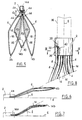
- FIG. 1 there is shown a filter according to the invention, referenced as a whole at 1, which has been placed in a vein 11.
- This filter is constituted by elastic tabs, for example the number of eight, gathered together in a head 2.
- This filter 1 comprises two different types of legs, more precisely a first series of four legs 4 capped by a second series of four other legs 14.
- the legs 4 and 14 have a meeting (or proximal) end 4a, 14a and a distal, free end, 4b, 14b. They are deployable or self-expanding radially to the general axis 6 of the filter, so that their free end 4b, 14b come into contact with the wall of the vessel when the filter is implanted there.
- the tabs 4, 14 respectively define a first corolla 8 and a second corolla 10 overhanging the first, both substantially conical with axis 6.
- the legs 14 are shorter than the legs 4.
- the opening marked with dotted lines 12 of the corolla 8 is located at a level lower than that marked with dotted lines 16 of the corolla 10.
- the legs are produced from at least one flexible wire folded back on itself substantially in the form of a loop, the outline of which defines a surface with the appearance of a petal.
- a loop of the first series and a loop of the second series respectively delimit surfaces referenced 18 and 20 which will advantageously be flat or slightly curved with convexity directed towards the outside (vessel wall).
- the legs of the same series are preferably spaced apart from each other without contact and each leg of one of the series is situated between two adjacent legs of the other series.
- each surface 20 covers, at least in projection and partially, a surface 18 and preferably, as shown here, two surfaces 18 which are directly adjacent to it.
- each of the legs 4 and 14 is here produced from a single wire 24 curved on itself so that its opposite free ends 26, 28 are brought together, ready to be fixed in the head 2.
- wire (s) it is possible to use in particular metal wires, of circular section of a few tenths of a millimeter, such as stainless steel of suitable quality, for example known by their registered trade name "Phynox".
- the legs 4 and 14 preferably have a narrow part 30 towards their meeting end and an end constricted part 32 towards their opposite free end, the constriction 32 being favorable to the relative rigidity of the legs.
- All the legs 4 of the first series and all those 14 of the second series have in the deployed position respectively a length L and a length L ' (L ⁇ L' ) which extend between their ends proximal and distal. They also preferably comprise substantially half of their respective length, a bulbous portion 34.
- the short legs 14 being advantageously more swollen than the long legs, this part 34 will, for the tab 14, a width of the greater than or equal to that the of the tab 4. It is noted that, preferably, the legs will all have a diamond shape.
- FIGS. 6 and 7 the tabs 4 and 14 have been shown respectively in side view, with here the curved profile which they will take naturally so that the filter 1, in an unstressed state, tends to deploy radially .
- These figures also show that, the tab 14 being shorter, it is, towards its proximal end, naturally more distant from the axis 6 (angle ⁇ ) than the tab 4 (angle ⁇ ).
- Figures 8 and 9 show a possible way of fixing the legs in the head or cap 2, which is here axially connectable, opposite, (by crimping) to a filter holding element, shown schematically in dotted lines 36 and which can be consisting of a flexible cable, tube or rod, for example made of biocompatible plastic, intended to allow the filter to be operated from outside the patient's body (in the manner provided for almost all current temporary filters) .
- a filter holding element shown schematically in dotted lines 36 and which can be consisting of a flexible cable, tube or rod, for example made of biocompatible plastic, intended to allow the filter to be operated from outside the patient's body (in the manner provided for almost all current temporary filters) .
- the head 2 which is substantially cylindrical, has, in the direction of the filter, an internal bore 38 (forming a recess or internal shoulder 39) in which the opposite free ends 26, 28 of the wires are arranged.
- These wires, bearing against the shoulder 39, will be blocked by means of a central part 40, substantially cylindrical, delimiting a peripheral annular space 42 for housing the wires which are regularly distributed there.
- the two opposite free ends of a wire are placed side by side and are joined on either side to the opposite free ends of the wire of a loop of a different series.
- the short legs 14 consist of a flexible wire of diameter D1 less than the diameter D2 of the long legs, this difference in diameter combined with the difference in length of the legs giving all the loops a substantially equal rigidity.
- D1 could be equal to approximately 0.25 mm and D2 to approximately 0.30 mm.
- a lug 14 of the second series has, in the deployed position and towards its meeting end with the head, an angle ⁇ of opening of the loop which it forms greater than or equal to the angle ⁇ opening a loop that has a tab 4 towards its proximal end 4a, in the deployed position.
- This angle ⁇ will preferably be between 30 ° and 50 °, the angle ⁇ preferably being between 15 ° and 25 ° (it will be noted that in the figures the angles ⁇ and ⁇ appear larger for reasons of clarity in particular).
- the filter according to the invention can be implemented in a manner known per se, by stripping or percutaneously (for example by the so-called "SELDINGER” technique) by using an implantation device comprising a flexible tubular sheath which may contain internally, the filter in radially constrained position.
- FIG. 10 shows the filter 1 disposed in the folded position in the interior passage 52 of such a sheath 50. In this position where the tabs 14 are in contact and cover the tabs 4 along the axis 6, there is practically no risk of tangling these legs.
- the invention is in no way limited to the embodiment described.
- all the legs have substantially the same length, the corollas 8 and 10 then being in contact and bearing on one another when the filter is opened and in its implanted position.
Abstract
Description
L'invention a pour objet un filtre sanguin perfectionné destiné à être placé dans un vaisseau du système circulatoire pour la retenue de caillots de sang.The invention relates to an improved blood filter intended to be placed in a vessel of the circulatory system for the retention of blood clots.
Bien entendu, il existe déjà sur le marché différents types de filtres sanguins, implantables généralement à l'intérieur de la veine cave arrivant au coeur pour arrêter, avant leur entrée dans le coeur, les éventuels caillots de sang pouvant se former et risquant d'entraîner des embolies.Of course, there are already on the market different types of blood filters, generally implantable inside the vena cava reaching the heart to stop, before their entry into the heart, any blood clots that can form and risk cause embolism.
Parmi ces filtres, on en connaît qui sont fabriqués à partir de fils métalliques bouclés assemblés entre eux par soudage ou sertissage pour constituer des pattes en "pétales", ces pattes en boucles formant, en position implantée du filtre, un petit panier tronconique disposé dans le vaisseau. Ces filtres ont notamment l'avantage d'être peu encombrants en position repliée et peuvent donc être facilement implantés. Un exemple peut être trouvé au brevet US 5133733 où les pattes en fils bouclés sont associées à des pattes rectilignes terminées par un crochet permettant au filtre de s'ancrer à la paroi du vaisseau, en constituant alors ce que l'on dénomme habituellement un filtre "définitif" (non retirable aisément). On notera qu'au demeurant ces pattes en fil(s) bouclé(s) sont également connues pour être utilisées sur des filtres dits "temporaires", c'est-à-dire dépourvus de crochets (ou équivalents) d'ancrage au vaisseau, afin de permettre leur retrait une fois que leur temps d'intervention est terminé. La demande FR 9209957 du 12 Août 1992 donne un exemple d'un tel filtre.Among these filters, we know which are made from looped metallic wires assembled together by welding or crimping to form legs in "petals", these looped legs forming, in the implanted position of the filter, a small frustoconical basket disposed in the ship. These filters have the particular advantage of being compact in the folded position and can therefore be easily installed. An example can be found in US patent 5133733 where the legs in looped wires are associated with rectilinear legs terminated by a hook allowing the filter to be anchored to the wall of the vessel, thus constituting what is usually called a filter. "final" (not easily removable). Note that these legs in looped wire (s) are also known to be used on so-called "temporary" filters, that is to say without hooks (or equivalent) for anchoring to the vessel. , to allow their removal once their intervention time is over. Application FR 9209957 of August 12, 1992 gives an example of such a filter.
Dans la pratique, on a toutefois constaté que ces filtres "en pétales" posaient souvent des problèmes liés à leur structure dans la mesure où la souplesse des fils augmente les risques d'emmêlement des pattes au moment de la pose dans le vaisseau, voire au moment du retrait pour les filtres temporaires.In practice, however, it has been found that these "petal" filters often pose problems related to their structure since the flexibility of the wires increases the risk of tangling of the legs when they are placed in the vessel, or even at time of removal for temporary filters.
La présente invention a pour objet de résoudre ces inconvénients en proposant un filtre perfectionné dont notamment la disposition relative particulière des pattes garantit une ouverture et un positionnement favorables du filtre dans le vaisseau, en limitant grandement les risques d'emmêlement, tout en favorisant le centrage du filtre.The object of the present invention is to resolve these drawbacks by proposing an improved filter including in particular the particular relative arrangement of the legs guarantees a favorable opening and positioning of the filter in the vessel, greatly limiting the risks of tangling, while promoting the centering of the filter.
Le filtre conforme à l'invention est tel que les pattes en boucles de fil(s) souple(s), définissant chacune le contour d'une surface, dont il est équipé sont réparties autour de la tête en une première et une seconde séries de pattes, la seconde série de pattes coiffant la première, la surface définie par l'une quelconque des boucles de la seconde série de pattes recouvrant, en tout ou partie, la surface définie par une boucle sous-jacente de la première série.The filter according to the invention is such that the legs in loops of flexible wire (s), each defining the outline of a surface, with which it is equipped are distributed around the head in a first and a second series of legs, the second series of legs covering the first, the surface defined by any of the loops of the second series of legs covering, in whole or in part, the surface defined by an underlying loop of the first series.
Dans ce cadre général des filtres "en pétales", l'invention s'applique tout particulièrement aux filtres "temporaires" dépourvus de moyens d'ancrage à la paroi du vaisseau et qui peuvent donc être implantés de manière amovible, l'invention permettant leur retrait aisé. En effet, la prévision sur ces filtres temporaires de deux séries superposées de boucles en fil, avec recouvrement au moins partiel comme indiqué ci-avant, permet au moment du retrait du filtre de le replier aisément sous un faible volume, les pattes se positionnant automatiquement les unes par rapport aux autres de manière ordonnée. Le filtre peut donc notamment être facilement et rapidement (re)introduit dans la gaine tubulaire utilisée couramment pour son retrait.In this general framework of "petal" filters, the invention applies very particularly to "temporary" filters devoid of means for anchoring to the wall of the vessel and which can therefore be implanted in a removable manner, the invention allowing their easy removal. Indeed, the provision on these temporary filters of two superimposed series of wire loops, with at least partial overlap as indicated above, allows the filter to be easily folded up when the filter is removed, the legs positioning themselves automatically relative to each other in an orderly fashion. The filter can therefore in particular be easily and quickly (re) introduced into the tubular sheath commonly used for its removal.
Selon une caractérisque de construction préférée de l'invention, les pattes seront toutes assemblées à une extrémité, sensiblement en une même zone de réunion, dans une tête commune et unique, en forme de calotte.According to a preferred construction characteristic of the invention, the legs will all be assembled at one end, substantially in the same meeting area, in a common and single head, in the shape of a cap.
Avantageusement, chaque patte d'une des séries sera disposée radialement entre deux pattes adjacentes de l'autre série, la surface définie par l'une quelconque des boucles de la seconde série de pattes recouvrant, en tout ou partie, deux surfaces définies respectivement par deux boucles adjacentes de la première série.Advantageously, each leg of one of the series will be arranged radially between two adjacent legs of the other series, the surface defined by any one of the loops of the second series of legs covering, in whole or in part, two surfaces defined respectively by two adjacent loops of the first series.
Selon une caractérisque d'un mode de réalisation préféré de l'invention, les pattes de la seconde série seront à la fois plus courtes et plus renflées que celles de la première série ; ces première et seconde séries étant déployables respectivement suivant une première et une seconde corolles superposées.According to a characteristic of a preferred embodiment of the invention, the legs of the second series will be both shorter and more swollen than those of the first series; these first and second series being deployable respectively according to a first and a second superimposed corollas.
L'invention et sa mise en oeuvre apparaîtront plus clairement de la description qui va suivre faite en référence aux dessins annexés donnés uniquement à titre d'illustration. Dans ces dessins :
- la figure 1 montre schématiquement, en perspective, le filtre de l'invention mis en place dans un vaisseau sanguin ;
- la figure 2 montre une vue agrandie du filtre de la figure 1, faite selon la flèche II sur la figure 1 ;
- la figure 3 est une vue agrandie d'un premier type de patte du filtre de la figure 1 ;
- la figure 4 est une vue agrandie d'un second type de patte du filtre de la figure 1 ;
- la figure 5 est une vue partielle agrandie d'un groupe de trois pattes du filtre de la figure 1 ;
- la figure 6 est une vue de côté dans le sens de la flèche VI de la figure 3 ;
- la figure 7 est une vue de côté dans le sens de la flèche VII de la figure 4 ;
- la figure 8 est une vue partielle, à plus grande échelle, avec arrachements, d'une possible réalisation de la tête du filtre de la figure 1 ;
- La figure 9 est une vue en coupe faite selon les flèches IX de la figure 8 ;
- la figure 10 représente, en position repliée du filtre dans son dispositif d'implantation, le groupe de pattes représenté à la figure 5.
- Figure 1 shows schematically, in perspective, the filter of the invention placed in a blood vessel;
- Figure 2 shows an enlarged view of the filter of Figure 1, taken along arrow II in Figure 1;
- Figure 3 is an enlarged view of a first type of tab of the filter of Figure 1;
- Figure 4 is an enlarged view of a second type of tab of the filter of Figure 1;
- Figure 5 is an enlarged partial view of a group of three legs of the filter of Figure 1;
- Figure 6 is a side view in the direction of arrow VI of Figure 3;
- Figure 7 is a side view in the direction of arrow VII of Figure 4;
- Figure 8 is a partial view, on a larger scale, with cutaway, of a possible embodiment of the filter head of Figure 1;
- Figure 9 is a sectional view taken along the arrows IX of Figure 8;
- FIG. 10 represents, in the folded position of the filter in its installation device, the group of tabs represented in FIG. 5.
Comme précisé précédemment, l'un des intérêts de l'invention étant son application aux filtres "temporaires", on ne décrira ci-après qu'un tel filtre même s'il doit être clair que l'invention peut s'appliquer à des filtres "définitifs", sur lesquels pourront alors être rapportés de manière connue en soi des moyens d'accrochage (se reporter par exemple au brevet US-A-5133733).As stated previously, one of the interests of the invention being its application to "temporary" filters, we will only describe below such a filter even if it must be clear that the invention can be applied to "final" filters, on which hooking means can then be attached in a manner known per se (see for example US-A-5133733).
En se reportant aux figures 1 et 2, on voit représenté un filtre conforme à l'invention, référencé dans son ensemble en 1, qui a été placé dans une veine 11. Ce filtre est constitué par des pattes élastiques, par exemple au nombre de huit, rassemblées entre elles dans une tête 2.Referring to Figures 1 and 2, there is shown a filter according to the invention, referenced as a whole at 1, which has been placed in a
Ce filtre 1 comprend deux types différents de pattes, plus précisément une première série de quatre pattes 4 coiffées par une seconde série de quatre autres pattes 14.This
Les pattes 4 et 14 présentent une extrémité de réunion (ou proximale) 4a, 14a et une extrémité distale, libre, 4b, 14b. Elles sont déployables ou auto-expansibles radialement à l'axe général 6 du filtre, pour que leur extrémité libre 4b, 14b viennent au contact de la paroi du vaisseau lorsque le filtre y est implanté.The
Liées à la tête, ou calotte de réunion 2, autour de laquelle elles sont radialement sensiblement régulièrement réparties, les pattes 4, 14 définissent respectivement une première corolle 8 et une seconde corolle 10 surplombant la première, toutes deux sensiblement coniques d'axe 6.Linked to the head, or
Avantageusement, les pattes 14 sont plus courtes que les pattes 4. Ainsi, l'ouverture marquée en pointillés 12 de la corolle 8, est située à un niveau inférieur à celle marquée en pointillés 16 de la corolle 10. Cet étagement, parallèlement à l'axe 6, des zones de contact des pattes avec la paroi du vaisseau donne une plus grande stabilité au filtre. De plus, cette prévision de pattes courtes et longues permet de replier le filtre sous un plus faible volume, facilitant encore son implantation ou son retrait dans le vaisseau.Advantageously, the
Comme il apparaît clairement à la figure 2, les pattes sont réalisées à partir d'au moins un fil souple replié sur lui-même sensiblement en forme de boucle, dont le contour définit une surface à aspect de pétale. Une boucle de la première série et une boucle de la deuxième série délimitent respectivement des surfaces référencées 18 et 20 qui seront avantageusement planes ou légèrement bombées à convexité dirigée vers l'extérieur (paroi du vaisseau). Les pattes d'une même série sont de préférence écartées les unes des autres sans contact et chaque patte d'une des séries est située entre deux pattes adjacentes de l'autre série. Les pattes des deux séries étant ainsi intercalées, chaque surface 20 couvre, au moins en projection et partiellement, une surface 18 et de préférence, comme représenté ici, deux surfaces 18 qui lui sont directement adjacentes.As it clearly appears in FIG. 2, the legs are produced from at least one flexible wire folded back on itself substantially in the form of a loop, the outline of which defines a surface with the appearance of a petal. A loop of the first series and a loop of the second series respectively delimit surfaces referenced 18 and 20 which will advantageously be flat or slightly curved with convexity directed towards the outside (vessel wall). The legs of the same series are preferably spaced apart from each other without contact and each leg of one of the series is situated between two adjacent legs of the other series. The legs of the two series being thus interposed, each
Plus particulièrement sur les figures 3 et 4, on remarquera que chacune des pattes 4 et 14 est ici réalisée à partir d'un fil unique 24 recourbé sur lui-même de manière que ses extrémités libres opposées 26, 28 soient rassemblées, prêtes à être fixées dans la tête 2.More particularly in FIGS. 3 and 4, it will be noted that each of the
En tant que fil(s), on pourra utiliser en particulier des fils métalliques, de section circulaire de quelques dixièmes de millimètres, tels qu'en acier inoxydable de qualité appropriée, par exemple connu sous leur nom de marque déposée "Phynox".As wire (s), it is possible to use in particular metal wires, of circular section of a few tenths of a millimeter, such as stainless steel of suitable quality, for example known by their registered trade name "Phynox".
Les pattes 4 et 14 présentent, de préférence, une partie étroite 30 vers leur extrémité de réunion et une partie extrême étranglée 32, vers leur extrémité libre opposée, l'étranglement 32 étant favorable à la rigidité relative des pattes. Toutes les pattes 4 de la première série et toutes celles 14 de la seconde série présentent en position déployée respectivement une longueur L et une longueur L' (L ≧ L') qui s'étendent entre leurs extrémités proximales et distales. Elles comportent également, de préférence sensiblement à la moitié de leur longueur respective, une partie ventrue 34. Les pattes courtes 14 étant avantageusement plus renflées que les pattes longues, cette partie 34 aura, pour la patte 14, une largeur l' supérieure ou égale à celle l de la patte 4. On notera que, de manière préférée, les pattes auront toutes une forme de losange.The
A la figure 5, on a représenté plus précisément, en hachuré, les zones de recouvrement 22 des surfaces 20 et 18. Le filtre est conformé de telle sorte que ces zones soient relativement importantes, notamment dans sa position repliée. De cette façon, ces zones assurent un recouvrement ordonné et stable des pattes de la première sèrie par celles de la seconde série. On remarquera ici deux points de "recouvrement" ou de "croisement" 44, 46 entre le fil d'une boucle supérieure 14 et le fil d'une boucle inférieure adjacente 4. Le point 44 est situé vers la zone rétrécie 30 et à proximité immédiate des extrémités 4a, 14a, c'est-à-dire à une distance d₁ depuis l'extrémité de réunion des pattes comprise entre quasiment cette extrémité et environ 1/4 de la longueur L. Le point 46 est situé vers la partie ventrue 34, de préférence après cette partie lorsque l'on se déplace en direction de l'extrémité distale des pattes, c'est-à-dire à une distance d₂ depuis l'extrémité de réunion des pattes comprise entre environ 1/2 et 3/4 de la longueur L des pattes 4.In Figure 5, there is shown more precisely, hatched, the
Sur les figures 6 et 7, les pattes 4 et 14 ont respectivement été représentées en vue de côté, avec ici le profil courbe qu'elles prendront naturellement de manière que le filtre 1, dans un état non contraint, ait tendance à se déployer radialement. Ces figures montrent en outre que, la patte 14 étant plus courte, elle est, vers son extrémité proximale, naturellement plus écartée de l'axe 6 (angle δ) que la patte 4 (angle τ).In FIGS. 6 and 7, the
Les figures 8 et 9 montrent une manière possible de fixer les pattes dans la tête ou calotte 2, laquelle est ici raccordable axialement, à l'opposé, (par sertissage) à un élément de maintien du filtre, schématisé en pointillés 36 et pouvant être constitué d'un câble, tube ou tige souple, par exemple en matière plastique biocompatible, destiné à permettre la manoeuvre du filtre depuis l'extérieur du corps du patient (à la manière de ce qui est prévu pour quasiment tous les filtres temporaires actuels).Figures 8 and 9 show a possible way of fixing the legs in the head or
Tel qu'illustré, la tête 2, sensiblement cylindrique, présente, en direction du filtre, un alésage intérieur 38 (formant un décrochement ou épaulement intérieur 39) dans lequel sont disposées les extrémités libres opposées 26, 28 des fils. Ces fils, en appui contre l'épaulement 39, seront bloqués grâce à une pièce centrale 40, sensiblement cylindrique, délimitant un espace annulaire périphérique 42 de logement des fils qui y sont régulièrement répartis.As illustrated, the
Les deux extrémités libres opposées d'un fil sont disposées côte à côte et sont accolées de part et d'autre aux extrémités libres opposées du fil d'une boucle d'une série différente.The two opposite free ends of a wire are placed side by side and are joined on either side to the opposite free ends of the wire of a loop of a different series.
Avantageusement, les pattes courtes 14 sont constituées d'un fil souple de diamètre D₁ inférieur au diamètre D₂ des pattes longues, cette différence de diamètre combinée à la différence de longueur des pattes donnant à toutes les boucles une rigidité sensiblement égale. Par exemple, D₁ pourra être égal à environ 0,25 mm et D₂ à environ 0,30 mm.Advantageously, the
En outre, on remarquera qu'une patte 14 de la seconde sérié présente, en position déployée et vers son extrémité de réunion à la tête, un angle α d'ouverture de la boucle qu'elle forme supérieur ou égal à l'angle β d'ouverture d'une boucle que présente une patte 4 vers son extrémité proximale 4a, en position déployée. Cet angle α sera de préférence compris entre 30° et 50°, l'angle β étant de préférence compris entre 15° et 25° (on notera que sur les figures les angles α et β apparaissent plus importants pour des raisons de clarté notamment).In addition, it will be noted that a
Le filtre selon l'invention pourra être mis en place de manière connue en soi, par dénudation ou par voie percutanée (par exemple par la technique dite de "SELDINGER") en recourant à un dispositif d'implantation comprenant une gaine tubulaire souple pouvant renfermer intérieurement, le filtre en position radialement contrainte.The filter according to the invention can be implemented in a manner known per se, by stripping or percutaneously (for example by the so-called "SELDINGER" technique) by using an implantation device comprising a flexible tubular sheath which may contain internally, the filter in radially constrained position.
A la figure 10, on a représenté le filtre 1 disposé en position repliée dans le passage intérieur 52 d'une telle gaine 50. Dans cette position où les pattes 14 sont en contact et recouvrent les pattes 4 le long de l'axe 6, il n'y a pratiquement pas de risque d'emmêlement de ces pattes.FIG. 10 shows the
Au moment du "lâcher" du filtre dans la veine, on observe également une expansion ordonnée des deux séries de pattes jusqu'à ce qu'elles viennent au contact de la paroi ; ces deux séries étant, de préférence, en contact entre elles durant une partie au moins de leur expansion radiale, pour favoriser leur guidage en ouverture, les angles d'écartement τ, δ donnés naturellement aux pattes 4, 14 respectivement par rapport à l'axe du filtre, étant adaptés en conséquence (τ ≦ δ), avec τ compris de préférence entre 10° et 30° et δ compris de préférence entre 15° et 40°.At the time of the "release" of the filter into the vein, there is also an ordered expansion of the two series of legs until they come into contact with the wall; these two series being preferably in contact with each other during at least part of their radial expansion, to favor their guiding during opening, the spacing angles τ, δ given naturally to the
Bien entendu, l'invention n'est nullement limitée au mode de réalisation décrit. Ainsi, on pourrait envisager que toutes les pattes aient sensiblement la même longueur, les corolles 8 et 10 étant alors en contact et en appui l'une sur l'autre lors de l'ouverture du filtre et dans sa position implantée. On pourrait également envisager d'employer un seul fil pour constituer toutes les pattes d'une même série, voire des deux.Of course, the invention is in no way limited to the embodiment described. Thus, it could be envisaged that all the legs have substantially the same length, the
Claims (11)
Applications Claiming Priority (2)
| Application Number | Priority Date | Filing Date | Title |
|---|---|---|---|
| FR9314248A FR2713081B1 (en) | 1993-11-29 | 1993-11-29 | Improved blood filter with two series of petal legs. |
| FR9314248 | 1993-11-29 |
Publications (1)
| Publication Number | Publication Date |
|---|---|
| EP0655228A1 true EP0655228A1 (en) | 1995-05-31 |
Family
ID=9453317
Family Applications (1)
| Application Number | Title | Priority Date | Filing Date |
|---|---|---|---|
| EP94402666A Withdrawn EP0655228A1 (en) | 1993-11-29 | 1994-11-22 | Endovascular blood filter with petal shaped two-stage filtering elements |
Country Status (2)
| Country | Link |
|---|---|
| EP (1) | EP0655228A1 (en) |
| FR (1) | FR2713081B1 (en) |
Cited By (75)
| Publication number | Priority date | Publication date | Assignee | Title |
|---|---|---|---|---|
| EP0852132A1 (en) * | 1997-01-03 | 1998-07-08 | B. BRAUN CELSA (société anonyme) | Blood filter with improved permeability |
| US6129739A (en) * | 1999-07-30 | 2000-10-10 | Incept Llc | Vascular device having one or more articulation regions and methods of use |
| US6179861B1 (en) | 1999-07-30 | 2001-01-30 | Incept Llc | Vascular device having one or more articulation regions and methods of use |
| US6203561B1 (en) | 1999-07-30 | 2001-03-20 | Incept Llc | Integrated vascular device having thrombectomy element and vascular filter and methods of use |
| US6214026B1 (en) | 1999-07-30 | 2001-04-10 | Incept Llc | Delivery system for a vascular device with articulation region |
| US6291475B1 (en) | 1997-12-17 | 2001-09-18 | Astrazeneca Ab | Bispidine antiarrhythmic compounds |
| US6371971B1 (en) | 1999-11-15 | 2002-04-16 | Scimed Life Systems, Inc. | Guidewire filter and methods of use |
| US6371969B1 (en) | 1997-05-08 | 2002-04-16 | Scimed Life Systems, Inc. | Distal protection device and method |
| US6371970B1 (en) | 1999-07-30 | 2002-04-16 | Incept Llc | Vascular filter having articulation region and methods of use in the ascending aorta |
| US6537295B2 (en) | 2001-03-06 | 2003-03-25 | Scimed Life Systems, Inc. | Wire and lock mechanism |
| US6544279B1 (en) | 2000-08-09 | 2003-04-08 | Incept, Llc | Vascular device for emboli, thrombus and foreign body removal and methods of use |
| US6544280B1 (en) | 1999-02-24 | 2003-04-08 | Scimed Life Systems, Inc. | Intravascular filter and method |
| US6589263B1 (en) | 1999-07-30 | 2003-07-08 | Incept Llc | Vascular device having one or more articulation regions and methods of use |
| US6616681B2 (en) | 2000-10-05 | 2003-09-09 | Scimed Life Systems, Inc. | Filter delivery and retrieval device |
| US6620148B1 (en) | 1999-08-04 | 2003-09-16 | Scimed Life Systems, Inc. | Filter flush system and methods of use |
| US6620182B1 (en) | 1999-07-30 | 2003-09-16 | Incept Llc | Vascular filter having articulation region and methods of use in the ascending aorta |
| US6652505B1 (en) | 1999-08-03 | 2003-11-25 | Scimed Life Systems Inc. | Guided filter with support wire and methods of use |
| US6663652B2 (en) | 1997-03-06 | 2003-12-16 | John M. K. Daniel | Distal protection device and method |
| US6663651B2 (en) | 2001-01-16 | 2003-12-16 | Incept Llc | Systems and methods for vascular filter retrieval |
| US6673090B2 (en) | 1999-08-04 | 2004-01-06 | Scimed Life Systems, Inc. | Percutaneous catheter and guidewire for filtering during ablation of myocardial or vascular tissue |
| US6689151B2 (en) | 2001-01-25 | 2004-02-10 | Scimed Life Systems, Inc. | Variable wall thickness for delivery sheath housing |
| WO2004049973A1 (en) * | 2002-11-29 | 2004-06-17 | Vascular Interventional Technologies Inc. | Embolus blood clot filter |
| US6755847B2 (en) | 2001-10-05 | 2004-06-29 | Scimed Life Systems, Inc. | Emboli capturing device and method of manufacture therefor |
| US6793666B2 (en) | 2001-12-18 | 2004-09-21 | Scimed Life Systems, Inc. | Distal protection mechanically attached filter cartridge |
| US6814740B2 (en) | 1999-10-27 | 2004-11-09 | Scimed Life Systems, Inc. | Retrieval device made of precursor alloy cable |
| WO2005123748A1 (en) | 2004-06-15 | 2005-12-29 | Astrazeneca Ab | Novel oxabispidine compounds and their use in the treatment of cardiac arrhythmias |
| US7354917B2 (en) | 2004-06-15 | 2008-04-08 | Astrazeneca Ab | Oxabispidine compounds and their use in the treatment of cardiac arrhythmias |
| US7651514B2 (en) | 2003-12-11 | 2010-01-26 | Boston Scientific Scimed, Inc. | Nose rider improvement for filter exchange and methods of use |
| US7662165B2 (en) | 1997-11-07 | 2010-02-16 | Salviac Limited | Embolic protection device |
| US7691123B2 (en) | 1997-05-08 | 2010-04-06 | Boston Scientific Scimed, Inc. | Percutaneous catheter and guidewire having filter and medical device deployment capabilities |
| US7695465B2 (en) | 2001-07-30 | 2010-04-13 | Boston Scientific Scimed, Inc. | Chronic total occlusion device with variable stiffness shaft |
| US7699866B2 (en) | 1999-07-16 | 2010-04-20 | Boston Scientific Scimed, Inc. | Emboli filtration system and methods of use |
| US7708770B2 (en) | 2001-11-09 | 2010-05-04 | Boston Scientific Scimed, Inc. | Stent delivery device with embolic protection |
| US7740644B2 (en) | 2003-02-24 | 2010-06-22 | Boston Scientific Scimed, Inc. | Embolic protection filtering device that can be adapted to be advanced over a guidewire |
| US7762403B2 (en) | 2003-02-24 | 2010-07-27 | Boston Scientific Scimed, Inc. | Flexible tube for cartridge filter |
| US7780611B2 (en) | 2003-05-01 | 2010-08-24 | Boston Scientific Scimed, Inc. | Medical instrument with controlled torque transmission |
| US7780697B2 (en) | 1997-11-07 | 2010-08-24 | Salviac Limited | Embolic protection system |
| US7785344B2 (en) | 2002-05-06 | 2010-08-31 | Boston Scientific Scimed, Inc. | Perfusion guidewire in combination with a distal filter |
| US7794472B2 (en) | 2004-08-11 | 2010-09-14 | Boston Scientific Scimed, Inc. | Single wire intravascular filter |
| US7799051B2 (en) | 1999-05-07 | 2010-09-21 | Salviac Limited | Support frame for an embolic protection device |
| US7875050B2 (en) | 1997-09-30 | 2011-01-25 | Target Therapeutics, Inc. | Mechanical clot treatment device |
| US7896861B2 (en) | 2004-10-21 | 2011-03-01 | Boston Scientific Scimed, Inc. | Catheter with a pre-shaped distal tip |
| US7901427B2 (en) | 1997-11-07 | 2011-03-08 | Salviac Limited | Filter element with retractable guidewire tip |
| US7927349B2 (en) | 2001-12-21 | 2011-04-19 | Salviac Limited | Support frame for an embolic protection device |
| US7928225B2 (en) | 2005-06-13 | 2011-04-19 | Astrazeneca Ab | Oxabispidine compounds for the treatment of cardiac arrhythmias |
| US7959584B2 (en) | 2002-05-29 | 2011-06-14 | Boston Scientific Scimed, Inc. | Dedicated distal protection guidewires |
| US7981134B2 (en) | 2001-10-19 | 2011-07-19 | Incept Llc | Vascular embolic filter exchange devices and methods of use thereof |
| US7998163B2 (en) | 2002-10-03 | 2011-08-16 | Boston Scientific Scimed, Inc. | Expandable retrieval device |
| US8002790B2 (en) | 1999-05-07 | 2011-08-23 | Salviac Limited | Support frame for an embolic protection device |
| US8038696B2 (en) | 2004-12-06 | 2011-10-18 | Boston Scientific Scimed, Inc. | Sheath for use with an embolic protection filter |
| US8057507B2 (en) | 2009-01-16 | 2011-11-15 | Novate Medical Limited | Vascular filter |
| US8070769B2 (en) | 2002-05-06 | 2011-12-06 | Boston Scientific Scimed, Inc. | Inverted embolic protection filter |
| US8123779B2 (en) | 2002-12-30 | 2012-02-28 | Boston Scientific Scimed, Inc. | Embolic protection device |
| US8123777B2 (en) | 2001-07-24 | 2012-02-28 | Incept, Llc | Apparatus and methods for aspirating emboli |
| US8162970B2 (en) | 2006-07-19 | 2012-04-24 | Novate Medical Limited | Vascular filter |
| US8241315B2 (en) | 2004-06-24 | 2012-08-14 | Boston Scientific Scimed, Inc. | Apparatus and method for treating occluded vasculature |
| US8337519B2 (en) | 2003-07-10 | 2012-12-25 | Boston Scientific Scimed, Inc. | Embolic protection filtering device |
| US8444669B2 (en) | 2008-12-15 | 2013-05-21 | Boston Scientific Scimed, Inc. | Embolic filter delivery system and method |
| US8468678B2 (en) | 2002-10-02 | 2013-06-25 | Boston Scientific Scimed, Inc. | Expandable retrieval device |
| US8480629B2 (en) | 2005-01-28 | 2013-07-09 | Boston Scientific Scimed, Inc. | Universal utility board for use with medical devices and methods of use |
| US8535344B2 (en) | 2003-09-12 | 2013-09-17 | Rubicon Medical, Inc. | Methods, systems, and devices for providing embolic protection and removing embolic material |
| US8647359B2 (en) | 2002-01-10 | 2014-02-11 | Boston Scientific Scimed, Inc. | Distal protection filter |
| US8668713B2 (en) | 2009-01-16 | 2014-03-11 | Novate Medical Limited | Vascular filter device |
| US8795322B2 (en) | 2002-04-01 | 2014-08-05 | W. L. Gore & Associates, Inc. | Methods of manufacture and use of endoluminal devices |
| US8821478B2 (en) | 2011-03-04 | 2014-09-02 | Boston Scientific Scimed, Inc. | Catheter with variable stiffness |
| US9023077B2 (en) | 2002-10-17 | 2015-05-05 | W.L. Gore & Associates, Inc. | Embolic filter frame having looped support strut elements |
| US9149609B2 (en) | 2006-10-16 | 2015-10-06 | Embolitech, Llc | Catheter for removal of an organized embolic thrombus |
| US9204887B2 (en) | 2012-08-14 | 2015-12-08 | W. L. Gore & Associates, Inc. | Devices and systems for thrombus treatment |
| US9301829B2 (en) | 2003-07-30 | 2016-04-05 | Boston Scientific Scimed, Inc. | Embolic protection aspirator |
| US9833304B2 (en) | 2009-01-16 | 2017-12-05 | Novate Medical Limited | Vascular filter device |
| US10624731B2 (en) | 2009-01-16 | 2020-04-21 | Novate Medical Limited | Vascular filter system |
| US10687930B2 (en) | 2013-03-15 | 2020-06-23 | Novate Medical Limited | Vascular filter device |
| US10806559B2 (en) | 2007-10-26 | 2020-10-20 | Surmodics Md, Llc | Intravascular guidewire filter system for pulmonary embolism protection and embolism removal or maceration |
| US11103263B2 (en) | 2015-07-24 | 2021-08-31 | Ichor Vascular Inc. | Embolectomy system and methods of making and using same |
| US11129702B2 (en) | 2018-05-09 | 2021-09-28 | Boston Scientific Scimed, Inc. | Pedal access embolic filtering sheath |
Families Citing this family (1)
| Publication number | Priority date | Publication date | Assignee | Title |
|---|---|---|---|---|
| JP4567918B2 (en) * | 2001-07-02 | 2010-10-27 | テルモ株式会社 | Intravascular foreign matter removal wire and medical device |
Citations (6)
| Publication number | Priority date | Publication date | Assignee | Title |
|---|---|---|---|---|
| DE3429850A1 (en) * | 1984-05-12 | 1986-02-20 | Ing. Walter Hengst GmbH & Co KG, 4400 Münster | Improved blood filter for insertion into veins |
| US4643184A (en) * | 1982-09-29 | 1987-02-17 | Mobin Uddin Kazi | Embolus trap |
| EP0270432A1 (en) * | 1986-11-17 | 1988-06-08 | Promed | Filter apparatus for blood clots |
| EP0350043A1 (en) * | 1988-07-08 | 1990-01-10 | Aubrey M. Palestrant | Mechanically locking blood clot filter |
| EP0430848A1 (en) * | 1989-11-28 | 1991-06-05 | William Cook Europe A/S | A collapsible filter for introduction in a blood vessel of a patient |
| US5152777A (en) * | 1989-01-25 | 1992-10-06 | Uresil Corporation | Device and method for providing protection from emboli and preventing occulsion of blood vessels |
-
1993
- 1993-11-29 FR FR9314248A patent/FR2713081B1/en not_active Expired - Fee Related
-
1994
- 1994-11-22 EP EP94402666A patent/EP0655228A1/en not_active Withdrawn
Patent Citations (7)
| Publication number | Priority date | Publication date | Assignee | Title |
|---|---|---|---|---|
| US4643184A (en) * | 1982-09-29 | 1987-02-17 | Mobin Uddin Kazi | Embolus trap |
| DE3429850A1 (en) * | 1984-05-12 | 1986-02-20 | Ing. Walter Hengst GmbH & Co KG, 4400 Münster | Improved blood filter for insertion into veins |
| EP0270432A1 (en) * | 1986-11-17 | 1988-06-08 | Promed | Filter apparatus for blood clots |
| EP0350043A1 (en) * | 1988-07-08 | 1990-01-10 | Aubrey M. Palestrant | Mechanically locking blood clot filter |
| US5152777A (en) * | 1989-01-25 | 1992-10-06 | Uresil Corporation | Device and method for providing protection from emboli and preventing occulsion of blood vessels |
| EP0430848A1 (en) * | 1989-11-28 | 1991-06-05 | William Cook Europe A/S | A collapsible filter for introduction in a blood vessel of a patient |
| US5133733A (en) * | 1989-11-28 | 1992-07-28 | William Cook Europe A/S | Collapsible filter for introduction in a blood vessel of a patient |
Cited By (134)
| Publication number | Priority date | Publication date | Assignee | Title |
|---|---|---|---|---|
| FR2758078A1 (en) * | 1997-01-03 | 1998-07-10 | Braun Celsa Sa | BLOOD FILTER WITH IMPROVED PERMEABILITY |
| US5968071A (en) * | 1997-01-03 | 1999-10-19 | B. Braun Celsa | Blood filtering device having improved permeability |
| EP0852132A1 (en) * | 1997-01-03 | 1998-07-08 | B. BRAUN CELSA (société anonyme) | Blood filter with improved permeability |
| US6663652B2 (en) | 1997-03-06 | 2003-12-16 | John M. K. Daniel | Distal protection device and method |
| US6371969B1 (en) | 1997-05-08 | 2002-04-16 | Scimed Life Systems, Inc. | Distal protection device and method |
| US7691123B2 (en) | 1997-05-08 | 2010-04-06 | Boston Scientific Scimed, Inc. | Percutaneous catheter and guidewire having filter and medical device deployment capabilities |
| US8486104B2 (en) | 1997-09-30 | 2013-07-16 | Stryker Corporation | Mechanical clot treatment device with distal filter |
| US7875050B2 (en) | 1997-09-30 | 2011-01-25 | Target Therapeutics, Inc. | Mechanical clot treatment device |
| US8328842B2 (en) | 1997-11-07 | 2012-12-11 | Salviac Limited | Filter element with retractable guidewire tip |
| US8430901B2 (en) | 1997-11-07 | 2013-04-30 | Salviac Limited | Embolic protection device |
| US8226678B2 (en) | 1997-11-07 | 2012-07-24 | Salviac Limited | Embolic protection device |
| US8241319B2 (en) | 1997-11-07 | 2012-08-14 | Salviac Limited | Embolic protection system |
| US8216270B2 (en) | 1997-11-07 | 2012-07-10 | Salviac Limited | Embolic protection device |
| US7972352B2 (en) | 1997-11-07 | 2011-07-05 | Salviac Limited | Embolic protection system |
| US8221448B2 (en) | 1997-11-07 | 2012-07-17 | Salviac Limited | Embolic protection device |
| US7662165B2 (en) | 1997-11-07 | 2010-02-16 | Salviac Limited | Embolic protection device |
| US8123776B2 (en) | 1997-11-07 | 2012-02-28 | Salviac Limited | Embolic protection system |
| US7901426B2 (en) | 1997-11-07 | 2011-03-08 | Salviac Limited | Embolic protection device |
| US7901427B2 (en) | 1997-11-07 | 2011-03-08 | Salviac Limited | Filter element with retractable guidewire tip |
| US8603131B2 (en) | 1997-11-07 | 2013-12-10 | Salviac Limited | Embolic protection device |
| US8057504B2 (en) | 1997-11-07 | 2011-11-15 | Salviac Limited | Embolic protection device |
| US7846176B2 (en) | 1997-11-07 | 2010-12-07 | Salviac Limited | Embolic protection system |
| US7842066B2 (en) | 1997-11-07 | 2010-11-30 | Salviac Limited | Embolic protection system |
| US7842063B2 (en) | 1997-11-07 | 2010-11-30 | Salviac Limited | Embolic protection device |
| US7837701B2 (en) | 1997-11-07 | 2010-11-23 | Salviac Limited | Embolic protection device |
| US7833242B2 (en) | 1997-11-07 | 2010-11-16 | Salviac Limited | Embolic protection device |
| US7780697B2 (en) | 1997-11-07 | 2010-08-24 | Salviac Limited | Embolic protection system |
| US8052716B2 (en) | 1997-11-07 | 2011-11-08 | Salviac Limited | Embolic protection system |
| US8852226B2 (en) | 1997-11-07 | 2014-10-07 | Salviac Limited | Vascular device for use during an interventional procedure |
| US6291475B1 (en) | 1997-12-17 | 2001-09-18 | Astrazeneca Ab | Bispidine antiarrhythmic compounds |
| US9119706B2 (en) | 1999-02-24 | 2015-09-01 | Boston Scientific Scimed Inc. | Intravascular filter and method |
| US8303618B2 (en) | 1999-02-24 | 2012-11-06 | Boston Scientific Scimed, Inc. | Intravascular filter and method |
| US6544280B1 (en) | 1999-02-24 | 2003-04-08 | Scimed Life Systems, Inc. | Intravascular filter and method |
| US7799051B2 (en) | 1999-05-07 | 2010-09-21 | Salviac Limited | Support frame for an embolic protection device |
| US8002790B2 (en) | 1999-05-07 | 2011-08-23 | Salviac Limited | Support frame for an embolic protection device |
| US7699866B2 (en) | 1999-07-16 | 2010-04-20 | Boston Scientific Scimed, Inc. | Emboli filtration system and methods of use |
| US6530939B1 (en) | 1999-07-30 | 2003-03-11 | Incept, Llc | Vascular device having articulation region and methods of use |
| US6129739A (en) * | 1999-07-30 | 2000-10-10 | Incept Llc | Vascular device having one or more articulation regions and methods of use |
| US6179861B1 (en) | 1999-07-30 | 2001-01-30 | Incept Llc | Vascular device having one or more articulation regions and methods of use |
| US6371970B1 (en) | 1999-07-30 | 2002-04-16 | Incept Llc | Vascular filter having articulation region and methods of use in the ascending aorta |
| US8617201B2 (en) | 1999-07-30 | 2013-12-31 | Incept Llc | Vascular device for emboli, thrombus and foreign body removal and methods of use |
| US6589263B1 (en) | 1999-07-30 | 2003-07-08 | Incept Llc | Vascular device having one or more articulation regions and methods of use |
| US6203561B1 (en) | 1999-07-30 | 2001-03-20 | Incept Llc | Integrated vascular device having thrombectomy element and vascular filter and methods of use |
| US6214026B1 (en) | 1999-07-30 | 2001-04-10 | Incept Llc | Delivery system for a vascular device with articulation region |
| US9283066B2 (en) | 1999-07-30 | 2016-03-15 | Incept Llc | Vascular device for emboli, thrombus and foreign body removal and methods of use |
| USRE43882E1 (en) | 1999-07-30 | 2012-12-25 | Incept, Llc | Vascular device for emboli, thrombus and foreign body removal and methods of use |
| US6620182B1 (en) | 1999-07-30 | 2003-09-16 | Incept Llc | Vascular filter having articulation region and methods of use in the ascending aorta |
| USRE43902E1 (en) | 1999-07-30 | 2013-01-01 | Incept, Llc | Vascular device for emboli, thrombus and foreign body removal and methods of use |
| US6652505B1 (en) | 1999-08-03 | 2003-11-25 | Scimed Life Systems Inc. | Guided filter with support wire and methods of use |
| US8444665B2 (en) | 1999-08-04 | 2013-05-21 | Boston Scientific Scimed, Inc. | Filter flush system and methods of use |
| US6673090B2 (en) | 1999-08-04 | 2004-01-06 | Scimed Life Systems, Inc. | Percutaneous catheter and guidewire for filtering during ablation of myocardial or vascular tissue |
| US6620148B1 (en) | 1999-08-04 | 2003-09-16 | Scimed Life Systems, Inc. | Filter flush system and methods of use |
| US8221434B2 (en) | 1999-10-27 | 2012-07-17 | Boston Scientific Scimed, Inc. | Retrieval device made of precursor alloy cable |
| US6814740B2 (en) | 1999-10-27 | 2004-11-09 | Scimed Life Systems, Inc. | Retrieval device made of precursor alloy cable |
| US6371971B1 (en) | 1999-11-15 | 2002-04-16 | Scimed Life Systems, Inc. | Guidewire filter and methods of use |
| US6544279B1 (en) | 2000-08-09 | 2003-04-08 | Incept, Llc | Vascular device for emboli, thrombus and foreign body removal and methods of use |
| US6616681B2 (en) | 2000-10-05 | 2003-09-09 | Scimed Life Systems, Inc. | Filter delivery and retrieval device |
| US6663651B2 (en) | 2001-01-16 | 2003-12-16 | Incept Llc | Systems and methods for vascular filter retrieval |
| US8460336B2 (en) | 2001-01-16 | 2013-06-11 | Incept Llc | Systems and methods for vascular filter retrieval |
| US6689151B2 (en) | 2001-01-25 | 2004-02-10 | Scimed Life Systems, Inc. | Variable wall thickness for delivery sheath housing |
| US6537295B2 (en) | 2001-03-06 | 2003-03-25 | Scimed Life Systems, Inc. | Wire and lock mechanism |
| US8262690B2 (en) | 2001-03-06 | 2012-09-11 | Boston Scientific Scimed, Inc. | Wire and lock mechanism |
| US8123777B2 (en) | 2001-07-24 | 2012-02-28 | Incept, Llc | Apparatus and methods for aspirating emboli |
| US7695465B2 (en) | 2001-07-30 | 2010-04-13 | Boston Scientific Scimed, Inc. | Chronic total occlusion device with variable stiffness shaft |
| US6755847B2 (en) | 2001-10-05 | 2004-06-29 | Scimed Life Systems, Inc. | Emboli capturing device and method of manufacture therefor |
| US8267956B2 (en) | 2001-10-19 | 2012-09-18 | Incept, Llc | Vascular embolic filter exchange devices and methods of use thereof |
| US7981134B2 (en) | 2001-10-19 | 2011-07-19 | Incept Llc | Vascular embolic filter exchange devices and methods of use thereof |
| US7708770B2 (en) | 2001-11-09 | 2010-05-04 | Boston Scientific Scimed, Inc. | Stent delivery device with embolic protection |
| US8579957B2 (en) | 2001-11-09 | 2013-11-12 | Boston Scientific Scimed, Inc. | Stent delivery device with embolic protection |
| US6793666B2 (en) | 2001-12-18 | 2004-09-21 | Scimed Life Systems, Inc. | Distal protection mechanically attached filter cartridge |
| US8114115B2 (en) | 2001-12-21 | 2012-02-14 | Salviac Limited | Support frame for an embolic protection device |
| US7927349B2 (en) | 2001-12-21 | 2011-04-19 | Salviac Limited | Support frame for an embolic protection device |
| US8647359B2 (en) | 2002-01-10 | 2014-02-11 | Boston Scientific Scimed, Inc. | Distal protection filter |
| US8801750B2 (en) | 2002-04-01 | 2014-08-12 | W.L. Gore & Associates, Inc. | Methods of manufacture and use of endoluminal devices |
| US8795322B2 (en) | 2002-04-01 | 2014-08-05 | W. L. Gore & Associates, Inc. | Methods of manufacture and use of endoluminal devices |
| US8070769B2 (en) | 2002-05-06 | 2011-12-06 | Boston Scientific Scimed, Inc. | Inverted embolic protection filter |
| US7785344B2 (en) | 2002-05-06 | 2010-08-31 | Boston Scientific Scimed, Inc. | Perfusion guidewire in combination with a distal filter |
| US7959584B2 (en) | 2002-05-29 | 2011-06-14 | Boston Scientific Scimed, Inc. | Dedicated distal protection guidewires |
| US8468678B2 (en) | 2002-10-02 | 2013-06-25 | Boston Scientific Scimed, Inc. | Expandable retrieval device |
| US7998163B2 (en) | 2002-10-03 | 2011-08-16 | Boston Scientific Scimed, Inc. | Expandable retrieval device |
| US9023076B2 (en) | 2002-10-17 | 2015-05-05 | W. L. Gore & Associates, Inc. | Embolic filter frame having looped support strut elements |
| US9023077B2 (en) | 2002-10-17 | 2015-05-05 | W.L. Gore & Associates, Inc. | Embolic filter frame having looped support strut elements |
| US9642691B2 (en) | 2002-10-17 | 2017-05-09 | W. L. Gore & Associates, Inc | Vessel occlusion device and method of using same |
| WO2004049973A1 (en) * | 2002-11-29 | 2004-06-17 | Vascular Interventional Technologies Inc. | Embolus blood clot filter |
| US8123779B2 (en) | 2002-12-30 | 2012-02-28 | Boston Scientific Scimed, Inc. | Embolic protection device |
| US8287564B2 (en) | 2003-02-24 | 2012-10-16 | Boston Scientific Scimed, Inc. | Embolic protection filtering device that can be adapted to be advanced over a guidewire |
| US7762403B2 (en) | 2003-02-24 | 2010-07-27 | Boston Scientific Scimed, Inc. | Flexible tube for cartridge filter |
| US8007510B2 (en) | 2003-02-24 | 2011-08-30 | Boston Scientific Scimed, Inc. | Embolic protection filtering device that can be adapted to be advanced over a guidewire |
| US7987994B2 (en) | 2003-02-24 | 2011-08-02 | Boston Scientific Scimed, Inc. | Flexible tube for cartridge filter |
| US7740644B2 (en) | 2003-02-24 | 2010-06-22 | Boston Scientific Scimed, Inc. | Embolic protection filtering device that can be adapted to be advanced over a guidewire |
| US8845552B2 (en) | 2003-05-01 | 2014-09-30 | Boston Scientific Scimed, Inc. | Medical instrument with controlled torque transmission |
| US8292829B2 (en) | 2003-05-01 | 2012-10-23 | Boston Scientific Scimed, Inc. | Medical instrument with controlled torque transmission |
| US7780611B2 (en) | 2003-05-01 | 2010-08-24 | Boston Scientific Scimed, Inc. | Medical instrument with controlled torque transmission |
| US8337519B2 (en) | 2003-07-10 | 2012-12-25 | Boston Scientific Scimed, Inc. | Embolic protection filtering device |
| US9301829B2 (en) | 2003-07-30 | 2016-04-05 | Boston Scientific Scimed, Inc. | Embolic protection aspirator |
| US8535344B2 (en) | 2003-09-12 | 2013-09-17 | Rubicon Medical, Inc. | Methods, systems, and devices for providing embolic protection and removing embolic material |
| US7651514B2 (en) | 2003-12-11 | 2010-01-26 | Boston Scientific Scimed, Inc. | Nose rider improvement for filter exchange and methods of use |
| US7354917B2 (en) | 2004-06-15 | 2008-04-08 | Astrazeneca Ab | Oxabispidine compounds and their use in the treatment of cardiac arrhythmias |
| US7648985B2 (en) | 2004-06-15 | 2010-01-19 | Astrazeneca Ab | Oxabispidine compounds and their use in the treatment of cardiac arrhythmias |
| WO2005123748A1 (en) | 2004-06-15 | 2005-12-29 | Astrazeneca Ab | Novel oxabispidine compounds and their use in the treatment of cardiac arrhythmias |
| US8241315B2 (en) | 2004-06-24 | 2012-08-14 | Boston Scientific Scimed, Inc. | Apparatus and method for treating occluded vasculature |
| US7794472B2 (en) | 2004-08-11 | 2010-09-14 | Boston Scientific Scimed, Inc. | Single wire intravascular filter |
| US7896861B2 (en) | 2004-10-21 | 2011-03-01 | Boston Scientific Scimed, Inc. | Catheter with a pre-shaped distal tip |
| US8403912B2 (en) | 2004-10-21 | 2013-03-26 | Boston Scientific Scimed, Inc. | Catheter with a pre-shaped distal tip |
| US8038696B2 (en) | 2004-12-06 | 2011-10-18 | Boston Scientific Scimed, Inc. | Sheath for use with an embolic protection filter |
| US8480629B2 (en) | 2005-01-28 | 2013-07-09 | Boston Scientific Scimed, Inc. | Universal utility board for use with medical devices and methods of use |
| US7928225B2 (en) | 2005-06-13 | 2011-04-19 | Astrazeneca Ab | Oxabispidine compounds for the treatment of cardiac arrhythmias |
| US11877922B2 (en) | 2006-07-19 | 2024-01-23 | Novate Medical Limited | Vascular filter |
| US11135049B2 (en) | 2006-07-19 | 2021-10-05 | Novate Medical Limited | Vascular filter |
| US8647360B2 (en) | 2006-07-19 | 2014-02-11 | Novate Medical Limited | Vascular filter |
| US8162970B2 (en) | 2006-07-19 | 2012-04-24 | Novate Medical Limited | Vascular filter |
| US9149609B2 (en) | 2006-10-16 | 2015-10-06 | Embolitech, Llc | Catheter for removal of an organized embolic thrombus |
| US10806559B2 (en) | 2007-10-26 | 2020-10-20 | Surmodics Md, Llc | Intravascular guidewire filter system for pulmonary embolism protection and embolism removal or maceration |
| US8444669B2 (en) | 2008-12-15 | 2013-05-21 | Boston Scientific Scimed, Inc. | Embolic filter delivery system and method |
| US8668713B2 (en) | 2009-01-16 | 2014-03-11 | Novate Medical Limited | Vascular filter device |
| US8821530B2 (en) | 2009-01-16 | 2014-09-02 | Novate Medical Limited | Vascular filter |
| US11672641B2 (en) | 2009-01-16 | 2023-06-13 | Novate Medical Limited | Vascular filter system |
| US8057507B2 (en) | 2009-01-16 | 2011-11-15 | Novate Medical Limited | Vascular filter |
| US9763765B2 (en) | 2009-01-16 | 2017-09-19 | Novate Medical Limited | Vascular filter |
| US9833304B2 (en) | 2009-01-16 | 2017-12-05 | Novate Medical Limited | Vascular filter device |
| US10470865B2 (en) | 2009-01-16 | 2019-11-12 | Novate Medical Limited | Vascular filter device |
| US10624731B2 (en) | 2009-01-16 | 2020-04-21 | Novate Medical Limited | Vascular filter system |
| US11413131B2 (en) | 2009-01-16 | 2022-08-16 | Novate Medical Limited | Vascular filter device |
| US11045298B2 (en) | 2009-01-16 | 2021-06-29 | Novate Medical Limited | Vascular filter |
| US8821478B2 (en) | 2011-03-04 | 2014-09-02 | Boston Scientific Scimed, Inc. | Catheter with variable stiffness |
| US10695084B2 (en) | 2012-08-14 | 2020-06-30 | W. L. Gore & Associates, Inc. | Devices and systems for thrombus treatment |
| US9204887B2 (en) | 2012-08-14 | 2015-12-08 | W. L. Gore & Associates, Inc. | Devices and systems for thrombus treatment |
| US11207095B2 (en) | 2012-08-14 | 2021-12-28 | W. L. Gore & Associates, Inc. | Devices and systems for thrombus treatment |
| US9579119B2 (en) | 2012-08-14 | 2017-02-28 | W. L. Gore & Associates, Inc. | Devices and systems for thrombus treatment |
| US9308007B2 (en) | 2012-08-14 | 2016-04-12 | W. L. Gore & Associates, Inc. | Devices and systems for thrombus treatment |
| US10687930B2 (en) | 2013-03-15 | 2020-06-23 | Novate Medical Limited | Vascular filter device |
| US11672639B2 (en) | 2013-03-15 | 2023-06-13 | Novate Medical Limited | Vascular filter system |
| US11103263B2 (en) | 2015-07-24 | 2021-08-31 | Ichor Vascular Inc. | Embolectomy system and methods of making and using same |
| US11129702B2 (en) | 2018-05-09 | 2021-09-28 | Boston Scientific Scimed, Inc. | Pedal access embolic filtering sheath |
Also Published As
| Publication number | Publication date |
|---|---|
| FR2713081B1 (en) | 1996-01-12 |
| FR2713081A1 (en) | 1995-06-09 |
Similar Documents
| Publication | Publication Date | Title |
|---|---|---|
| EP0655228A1 (en) | Endovascular blood filter with petal shaped two-stage filtering elements | |
| EP0582493B1 (en) | Vascular filter with triangulated legs | |
| EP0852132B1 (en) | Blood filter with improved permeability | |
| EP0661955B1 (en) | Medical kit comprising a filter and a device for placing said filter in the vessel | |
| EP0323333B1 (en) | Anti-embolic filter | |
| EP1103233B1 (en) | Monobloc blood filter production method | |
| FR2737404A1 (en) | PROSTHESIS IMPLANTABLE IN A HUMAN OR ANIMAL DUCT, SUCH AS A WALL ENLARGEMENT, OR A PROSTHESIS FOR ANEVRISM | |
| EP0270432B1 (en) | Filter apparatus for blood clots | |
| EP0759287B1 (en) | Filter for permanent use having an opening for the passage of medical devices and method of manufacture | |
| EP1786368B1 (en) | Valve prosthesis | |
| EP1791500B1 (en) | Interchangeable prosthetic valve | |
| FR2737654A1 (en) | FILTRATION UNIT FOR THE RETENTION OF BLOOD CLOTS | |
| EP0843538B1 (en) | Stent for expanding physiological vessels | |
| FR2694687A1 (en) | Intra-vascular prosthesis for blood filtration and clot prevention - comprises series of flexible threads formed into arrangement of shaped loops, secured to distal end of tubular support portion | |
| FR2710833A1 (en) | Device for implanting a medical prosthesis in a conduit of a human or animal body and method of centering such a device. | |
| EP0579523A1 (en) | Vascular prosthesis for aneurisma treatment | |
| FR2666980A1 (en) | Blood filtration unit and device for introducing such a unit into the blood circulation | |
| EP0605276A1 (en) | Device for selective use as a temporary blood-filter | |
| FR2657261A1 (en) | Device for temporary implantation of a blood filter in a vein of the human body | |
| FR2718950A1 (en) | Temporary or long-term blood filter | |
| FR2587901A1 (en) | Device intended to stop the circulation of thrombi in vessels | |
| FR2719976A1 (en) | Set forming tray for Japanese aquaculture lantern. | |
| EP0121447A1 (en) | Embolic filter | |
| FR2672487A1 (en) | Adaptable self-centring vein filter which can be implanted on the blood path | |
| EP0873093A1 (en) | Aortoiliac endoprosthesis |
Legal Events
| Date | Code | Title | Description |
|---|---|---|---|
| PUAI | Public reference made under article 153(3) epc to a published international application that has entered the european phase |
Free format text: ORIGINAL CODE: 0009012 |
|
| AK | Designated contracting states |
Kind code of ref document: A1 Designated state(s): AT BE DE ES GB IT |
|
| 17P | Request for examination filed |
Effective date: 19951103 |
|
| STAA | Information on the status of an ep patent application or granted ep patent |
Free format text: STATUS: THE APPLICATION IS DEEMED TO BE WITHDRAWN |
|
| 18D | Application deemed to be withdrawn |
Effective date: 19970603 |