EP0654838A1 - Device comprising high-temperature fuel cells and method of starting said device - Google Patents
Device comprising high-temperature fuel cells and method of starting said device Download PDFInfo
- Publication number
- EP0654838A1 EP0654838A1 EP93810817A EP93810817A EP0654838A1 EP 0654838 A1 EP0654838 A1 EP 0654838A1 EP 93810817 A EP93810817 A EP 93810817A EP 93810817 A EP93810817 A EP 93810817A EP 0654838 A1 EP0654838 A1 EP 0654838A1
- Authority
- EP
- European Patent Office
- Prior art keywords
- battery
- prereformer
- air
- heat
- channel system
- Prior art date
- Legal status (The legal status is an assumption and is not a legal conclusion. Google has not performed a legal analysis and makes no representation as to the accuracy of the status listed.)
- Withdrawn
Links
Images

Classifications
-
- H—ELECTRICITY
- H01—ELECTRIC ELEMENTS
- H01M—PROCESSES OR MEANS, e.g. BATTERIES, FOR THE DIRECT CONVERSION OF CHEMICAL ENERGY INTO ELECTRICAL ENERGY
- H01M8/00—Fuel cells; Manufacture thereof
- H01M8/24—Grouping of fuel cells, e.g. stacking of fuel cells
- H01M8/2465—Details of groupings of fuel cells
- H01M8/247—Arrangements for tightening a stack, for accommodation of a stack in a tank or for assembling different tanks
-
- H—ELECTRICITY
- H01—ELECTRIC ELEMENTS
- H01M—PROCESSES OR MEANS, e.g. BATTERIES, FOR THE DIRECT CONVERSION OF CHEMICAL ENERGY INTO ELECTRICAL ENERGY
- H01M8/00—Fuel cells; Manufacture thereof
- H01M8/04—Auxiliary arrangements, e.g. for control of pressure or for circulation of fluids
- H01M8/04007—Auxiliary arrangements, e.g. for control of pressure or for circulation of fluids related to heat exchange
- H01M8/04014—Heat exchange using gaseous fluids; Heat exchange by combustion of reactants
-
- H—ELECTRICITY
- H01—ELECTRIC ELEMENTS
- H01M—PROCESSES OR MEANS, e.g. BATTERIES, FOR THE DIRECT CONVERSION OF CHEMICAL ENERGY INTO ELECTRICAL ENERGY
- H01M8/00—Fuel cells; Manufacture thereof
- H01M8/06—Combination of fuel cells with means for production of reactants or for treatment of residues
- H01M8/0606—Combination of fuel cells with means for production of reactants or for treatment of residues with means for production of gaseous reactants
- H01M8/0612—Combination of fuel cells with means for production of reactants or for treatment of residues with means for production of gaseous reactants from carbon-containing material
- H01M8/0625—Combination of fuel cells with means for production of reactants or for treatment of residues with means for production of gaseous reactants from carbon-containing material in a modular combined reactor/fuel cell structure
-
- H—ELECTRICITY
- H01—ELECTRIC ELEMENTS
- H01M—PROCESSES OR MEANS, e.g. BATTERIES, FOR THE DIRECT CONVERSION OF CHEMICAL ENERGY INTO ELECTRICAL ENERGY
- H01M8/00—Fuel cells; Manufacture thereof
- H01M8/10—Fuel cells with solid electrolytes
- H01M8/12—Fuel cells with solid electrolytes operating at high temperature, e.g. with stabilised ZrO2 electrolyte
- H01M2008/1293—Fuel cells with solid oxide electrolytes
-
- H—ELECTRICITY
- H01—ELECTRIC ELEMENTS
- H01M—PROCESSES OR MEANS, e.g. BATTERIES, FOR THE DIRECT CONVERSION OF CHEMICAL ENERGY INTO ELECTRICAL ENERGY
- H01M2300/00—Electrolytes
- H01M2300/0017—Non-aqueous electrolytes
- H01M2300/0065—Solid electrolytes
- H01M2300/0068—Solid electrolytes inorganic
- H01M2300/0071—Oxides
- H01M2300/0074—Ion conductive at high temperature
-
- H—ELECTRICITY
- H01—ELECTRIC ELEMENTS
- H01M—PROCESSES OR MEANS, e.g. BATTERIES, FOR THE DIRECT CONVERSION OF CHEMICAL ENERGY INTO ELECTRICAL ENERGY
- H01M8/00—Fuel cells; Manufacture thereof
- H01M8/24—Grouping of fuel cells, e.g. stacking of fuel cells
- H01M8/249—Grouping of fuel cells, e.g. stacking of fuel cells comprising two or more groupings of fuel cells, e.g. modular assemblies
-
- Y—GENERAL TAGGING OF NEW TECHNOLOGICAL DEVELOPMENTS; GENERAL TAGGING OF CROSS-SECTIONAL TECHNOLOGIES SPANNING OVER SEVERAL SECTIONS OF THE IPC; TECHNICAL SUBJECTS COVERED BY FORMER USPC CROSS-REFERENCE ART COLLECTIONS [XRACs] AND DIGESTS
- Y02—TECHNOLOGIES OR APPLICATIONS FOR MITIGATION OR ADAPTATION AGAINST CLIMATE CHANGE
- Y02E—REDUCTION OF GREENHOUSE GAS [GHG] EMISSIONS, RELATED TO ENERGY GENERATION, TRANSMISSION OR DISTRIBUTION
- Y02E60/00—Enabling technologies; Technologies with a potential or indirect contribution to GHG emissions mitigation
- Y02E60/30—Hydrogen technology
- Y02E60/50—Fuel cells
Definitions
- the invention relates to a device with high-temperature fuel cells according to the preamble of claim 1. It also relates to a method for operating the device.
- the fuel gas consists mainly of methane (natural gas), to which water vapor has been added, before it is fed into the facility.
- methane and water are catalytically converted into hydrogen and carbon monoxide.
- the operating temperature of the prereformer is around 800 ° C, that of the fuel cells around 850 to 900 ° C.
- the application mentioned relates only to the stationary operating state.
- the characteristic of the first independent claim specifies constructive measures with which the task can be solved.
- the second independent claim relates to the starting method according to the invention.
- the or each prereformer can be heated up to operating temperature when starting up.
- the air supply is in operation during this heating phase; it supplies the oxygen required for the auxiliary burners.
- Fuel gas is advantageously used for the auxiliary burners; an additional gas such as hydrogen is therefore not required in the process according to the invention.
- the third channel system is thermally conductive to the first.
- the hot combustion gases generated by the auxiliary burners preheat the air fed into the first duct system.
- the preheated air in turn heats up the fuel cells before it reaches the auxiliary burners in the third duct system.
- the fuel gas supply to the fuel cells can be opened.
- the fuel gas will first implemented in a prereformer in a CO / H2 mixture. This mixture rinses and fills the gas spaces of the cells.
- the combustion can then be ignited in the post-combustion chamber, which is located between the cell stack and the casing.
- the fuel cells are further heated by means of the heat generated by the auxiliary burners and by the heat generated during the afterburning.
- the auxiliary burners can be switched off. This essentially completes the start-up process.
- the dependent claims 2 to 6 relate to different embodiments of the device according to the invention, the claims 8 to 10 each relate to a favorable choice of an operating parameter.
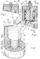
- the device shown in FIG. 1 comprises a cell stack 1, a cylindrical container 200 and a multilayer casing 4. Except for the container 200, this device has essentially already been described in the European application 92810572.5.
- the shell consists of an outer shell wall 400 with an air supply pipe 40, from bodies 420 and 421, which are made of a heat-insulating material, and from a duct system for air, with annular-gap channels 411, 415, 417, radial cavities 412, 413 and radial Channels 416.
- the first channel system the air required for the current-supplying reaction is preheated.
- the post-combustion chamber 11 is located between the stack 1 and the first duct system.
- FIG. 1 A cross section through the container 200 and the upper part of the cell stack 1 is shown in FIG.
- the prereformer 2 which is toroidal and contains a porous material which catalytically converts the fuel gas supplied via line 30 at 800 ° C. into a CO / H2 mixture.
- the direction of flow of the gas is indicated by arrows in the prereformer 2.
- the mixture produced enters the cell stack 1 via the line 12.
- the toroidal wall of the prereformer 2 forms, together with the lines 30, 3 and 12, the second channel system.
- a cylindrical filler body 220 and a cup-shaped body 221 together with the prereformer 2 form the third channel system, in which the exhaust gas flows through annularly shaped channels 211, 212, 213 and the radial cavity 214 during operation of the device. Arrows indicate the direction of flow of the exhaust gas.
- the third duct system also includes the line 21, via which the afterburning chamber 11 is connected to the container 200 is.
- the bodies 220 and 221 are made of a heat-insulating material.
- the cylindrical wall 4 'and the top surface 4' 'of the container 200 form the heat-conducting connection between the third and the first channel system.
- the air flowing in the first duct system is preheated with the exhaust gas heat.
- the wall of the prereformer 2 and the line 3 together form the heat-conducting connection between the third and the second channel system.
- the fuel gas supplied is heated with the hot exhaust gas.
- auxiliary burner 6 in the third channel system, which can be fed with fuel gas via line 60 and which is arranged with respect to prereformer 2 such that the prereformer 2 can be heated to operating temperature by the combustion gases.
- the combustion takes place with the supply of air via line 21.
- the auxiliary burner flame can be ignited with an electrically generated spark; a corresponding ignition device is not shown in the drawing.
- FIG. 3 shows a modified form of the container 200, in which a heat exchanger 5 is integrated for heating domestic water with exhaust gas.
- FIGS. 1 and 2 A device is shown in FIGS. 1 and 2, which comprises only one cell stack 1.
- two or more cell stacks 1 can also be connected together in parallel.
- the cell stacks can each be part of a module, with the individual modules having the same structure to have.
- the device in Figure 1 is an example of such a module.
- the Prereformer 2 is integrated in the module. It is also possible to provide the prereformer 2 outside the module. In this case, a common prereformer can be used for all modules.
- the device according to the invention comprises at least one cell stack 1, a prereformer 2, a heater 3 for the fuel gas and an air preheater 4, which is at the same time designed as a shell of the cell stack; in addition, a water heater 5 can be provided.
- These components can be represented schematically as a chain of blocks: see FIG. 5, the same reference numerals being used for the blocks as for the corresponding components of the device.
- FIG. 4 shows schematically which temperature profile - in the stationary operating state - for the air, the fuel gas, the exhaust gas and the process water can be assigned to blocks 1 to 5.
- the strips labeled with the Roman numerals I to V correspond to blocks 1 to 5 of FIG. 5; the x-axis indicates the linear sequence of the blocks.
- the curve pieces 401 and 101a in FIG. 4 correspond to the air temperature, the curve pieces 301, 201 and 101b the gas temperature, the curve pieces 102, 103, 202, 302, 402 and 502 the exhaust gas temperature and the curve piece 501 the water temperature.
- the vertical curve piece 103 in strip I indicates the temperature jump that arises from the afterburning.
- the vertical arrows 103b, 203 and 303 indicate the heat transfer between exhaust gas and fuel gas
- the arrows 103a and 403 the heat transfer between exhaust gas and air
- the arrow 503 the heat transfer between exhaust gas and process water.
- the arrow 404 stands for the heat dissipated via the casing 4.
- Points W, A and F stand for the feed points of water, air and fuel gas.
- the plus and minus poles on block 1 refer to the battery poles.
Abstract
Description
Die Erfindung betrifft eine Einrichtung mit Hochtemperatur-Brennstoffzellen gemäss Oberbegriff von Anspruch 1. Sie betrifft auch ein Verfahren zum Betrieb der Einrichtung.The invention relates to a device with high-temperature fuel cells according to the preamble of
Luft und Brenngas reagieren in den Brennstoffzellen und erzeugen dabei eine elektrische Leistung. Das Brenngas besteht vor dem Einspeisen in die Einrichtung vorwiegend aus Methan (Erdgas), dem Wasserdampf zugesetzt ist. Im Prereformer wird Methan und Wasser katalytisch in Wasserstoff und Kohlenmonoxid umgewandelt. Bei den bekannten Einrichtungen ist die Betriebstemperatur des Prereformers rund 800°C, jene der Brennstoffzellen rund 850 bis 900°C.
Eine gattungsgemässe Einrichtung, nämlich ein Zellenstapel mit einer wärmedämmenden Hülle, ist aus der europäischen Anmeldung 92810572.5 (= P.6511) bekannt. Die für die Reaktion benötigte Luft wird in dieser Einrichtung dazu benutzt, die aus dem Zellenstapel wegfliessende Wärme in der Hülle aufzunehmen und wieder zum Reaktionsort zurückzuführen. Die genannte Anmeldung bezieht sich nur auf den stationären Betriebszustand. Wie dieser Betriebszustand herzustellen ist, wie also das Anfahren des Betriebs vorzunehmen ist, ist noch ein offenes Problem. Aus der Druckschrift "Proceedings of the Third International Symposium on Solid Oxide Fuel Cells" (edited by S.C.Singhal and H.Iwahara, 1993) ist eine Einrichtung bekannt, bei der beim Anfahren Wasserstoff als Brenngas verwendet wird und die Luft mittels elektrischer Widerstandsheizungen vorgewärmt wird (siehe insbesondere Fig.2 und Fig.5 in dieser Druckschrift.)Air and fuel gas react in the fuel cells and generate electrical power. The fuel gas consists mainly of methane (natural gas), to which water vapor has been added, before it is fed into the facility. In the pre-reformer, methane and water are catalytically converted into hydrogen and carbon monoxide. In the known devices, the operating temperature of the prereformer is around 800 ° C, that of the fuel cells around 850 to 900 ° C.
A generic device, namely a cell stack with a heat-insulating cover, is known from European application 92810572.5 (= P.6511). The air required for the reaction is used in this device to absorb the heat flowing away from the cell stack in the casing and to return it to the reaction site. The application mentioned relates only to the stationary operating state. How to establish this operating state, such as starting operation is still an open problem. From the publication "Proceedings of the Third International Symposium on Solid Oxide Fuel Cells" (edited by SCSinghal and H.Iwahara, 1993), a device is known in which hydrogen is used as fuel gas when starting and the air is preheated by means of electrical resistance heaters ( see in particular Fig. 2 and Fig. 5 in this publication.)
Es ist Aufgabe der vorliegenden Erfindung, die in der oben genannten Anmeldung beschriebene Vorrichtung derart weiter zu entwickeln, dass das Anfahren auf eine einfachere Weise als beim bekannten Anfahrverfahren durchführbar ist. Das Kennzeichen des ersten unabhängigen Anspruchs gibt konstruktive Massnahmen an, mit denen die Aufgabe lösbar ist. Der zweite unabhängige Anspruch bezieht sich auf das erfindungsgemässe Anfahrverfahren.It is an object of the present invention to further develop the device described in the abovementioned application in such a way that starting can be carried out in a simpler manner than in the known starting method. The characteristic of the first independent claim specifies constructive measures with which the task can be solved. The second independent claim relates to the starting method according to the invention.
Mit den Hilfsbrennern, die erfindungsgemäss im Kanalsystem für das Abgas angeordnet sind, lässt sich der oder jeder Prereformer beim Anfahren auf Betriebstemperatur aufheizen. Während dieser Aufheizphase ist die Luftzufuhr in Betrieb; sie liefert den für die Hilfsbrenner benötigten Sauerstoff. Vorteilhafterweise wird für die Hilfsbrenner Brenngas verwendet; ein zusätzliches Gas wie beispielsweise Wasserstoff wird daher beim erfindungsgemässen Verfahren nicht benötigt.With the auxiliary burners, which according to the invention are arranged in the duct system for the exhaust gas, the or each prereformer can be heated up to operating temperature when starting up. The air supply is in operation during this heating phase; it supplies the oxygen required for the auxiliary burners. Fuel gas is advantageously used for the auxiliary burners; an additional gas such as hydrogen is therefore not required in the process according to the invention.
Das dritte Kanalsystem steht mit dem ersten in wärmeleitender Verbindung. Dadurch wird durch die heissen Verbrennungsgase, welche die Hilfsbrenner erzeugen, die in das erste Kanalsystem eingespeiste Luft vorgewärmt. Die vorgewärmte Luft ihrerseits erwärmt die Brennstoffzellen, bevor sie zu den Hilfsbrennern im dritten Kanalsystem gelangt. Wenn der oder jeder Prereformer Betriebstemperatur angenommen hat, kann die Brenngaszufuhr zu den Brennstoffzellen geöffnet werden. Das Brenngas wird zunächst im Prereformer in ein CO/H₂-Gemisch umgesetzt. Dieses Gemisch spült und füllt die Gasräume der Zellen. Danach kann die Verbrennung im Nachverbrennungsraum, der sich zwischen Zellenstapel und Hülle befindet, gezündet werden. Die Brennstoffzellen werden mittels der durch die Hilfsbrenner sowie durch die bei der Nachverbrennung erzeugten Wärme weiter aufgeheizt. Wenn die Batterie in den stromliefernden Betrieb übergeht, können die Hilfsbrenner abschaltet werden. Der Anfahrvorgang ist damit im wesentlichen abgeschlossen.The third channel system is thermally conductive to the first. As a result, the hot combustion gases generated by the auxiliary burners preheat the air fed into the first duct system. The preheated air in turn heats up the fuel cells before it reaches the auxiliary burners in the third duct system. When the or each prereformer has reached operating temperature, the fuel gas supply to the fuel cells can be opened. The fuel gas will first implemented in a prereformer in a CO / H₂ mixture. This mixture rinses and fills the gas spaces of the cells. The combustion can then be ignited in the post-combustion chamber, which is located between the cell stack and the casing. The fuel cells are further heated by means of the heat generated by the auxiliary burners and by the heat generated during the afterburning. When the battery goes into power supply, the auxiliary burners can be switched off. This essentially completes the start-up process.
Die abhängigen Ansprüche 2 bis 6 betreffen verschiedene Ausführungsformen der erfindungsgemässen Einrichtung, die Ansprüche 8 bis 10 beziehen sich jeweils auf eine günstige Wahl eines Betriebsparameters.The
Nachfolgend wird die Erfindung im Zusammenhang mit den Zeichnungen näher erläutert. Es zeigen:
- Fig. 1
- eine erfindungsgemässe Einrichtung, teilweise aufgeschnitten,
- Fig. 2
- Querschnitt durch den Prereformerteil der Einrichtung von Fig.1,
- Fig. 3
- ausschnittsweise einen Prereformerteil mit einem Wassererwärmer,
- Fig. 4
- ein Diagramm, das schematisch den Temperaturverlauf in der erfindungsgemässen Einrichtung während des stromliefernden Betriebs darstellt, und
- Fig. 5
- ein Blockschema, das dem Diagramm der Fig.4 zugeordnet ist.
- Fig. 1
- a device according to the invention, partially cut open,
- Fig. 2
- Cross-section through the prereformer part of the device from FIG. 1,
- Fig. 3
- sections of a pre-reformer part with a water heater,
- Fig. 4
- a diagram which schematically shows the temperature profile in the device according to the invention during the power supply operation, and
- Fig. 5
- a block diagram associated with the diagram of Figure 4.
Die in Fig.1 dargestellte Einrichtung umfasst einen Zellenstapel 1, einen zylindrischen Behälter 200 und eine mehrschichtige Hülle 4. Bis auf den Behälter 200 ist im wesentlichen diese Einrichtung bereits in der europäischen Anmeldung 92810572.5 beschrieben worden. Die Hülle besteht aus einer äusseren Hüllenwand 400 mit einem Luftzufuhrstutzen 40, aus Körpern 420 und 421, die aus einem wärmedämmenden Material gefertigt sind, sowie aus einem Kanalsystem für Luft, mit ringspaltförmigen Kanälen 411, 415, 417, radialen Hohlräumen 412, 413 und radialen Kanälen 416. In diesem Kanalsystem - dem ersten Kanalsystem - wird die für die stromliefernde Reaktion benötigte Luft vorgewärmt. Zwischen dem Stapel 1 und dem ersten Kanalsystem befindet sich der Nachverbrennungsraum 11.The device shown in FIG. 1 comprises a
Ein Querschnitt durch den Behälter 200 und den oberen Teil des Zellenstapels 1 ist in Fig.2 gezeigt. In diesem Behälter 200 befindet sich der Prereformer 2, der torusförmig ausgebildet ist und ein poröses Material enthält, welches das über die Leitung 30 zugeführte Brenngas bei 800°C katalytisch in ein CO/H₂-Gemisch umsetzt. Mit Pfeilen im Prereformer 2 ist die Fliessrichtung des Gases angegeben. Über die Leitung 12 tritt das erzeugte Gemisch in den Zellenstapel 1 ein. Die torusförmige Wandung des Prereformers 2 bildet zusammen mit den Leitungen 30, 3 und 12 das zweite Kanalsystem.A cross section through the
Ein zylindrischer Füllkörper 220 und ein topfförmiger Körper 221 bilden zusammen mit dem Prereformer 2 das dritte Kanalsystem, in dem beim Betrieb der Einrichtung das Abgas durch ringspaltförmige Kanäle 211, 212, 213 und den radialen Hohlraum 214 fliesst. Pfeile geben die Fliessrichtung des Abgases an. Zum dritten Kanalsystem gehört auch die Leitung 21, über die der Nachverbrennungsraum 11 mit dem Behälter 200 verbunden ist. Die Körper 220 und 221 sind aus einem wärmedämmenden Material gefertigt.A
Die zylindrische Wand 4' und die Deckfläche 4'' des Behälters 200 bilden die wärmeleitende Verbindung zwischen dem dritten und dem ersten Kanalsystem. Hier wird die im ersten Kanalsystem fliessende Luft mit der Abgaswärme vorgewärmt. Die Wandung des Prereformers 2 und die Leitung 3 bilden zusammen die wärmeleitende Verbindung zwischen dem dritten und dem zweiten Kanalsystem. In der Leitung 3 wird das zugeführte Brenngas mit dem heissen Abgas erhitzt.The cylindrical wall 4 'and the top surface 4' 'of the
Erfindungsgemäss befindet sich im dritten Kanalsystem ein Hilfsbrenner 6, der über die Leitung 60 mit Brenngas speisbar ist und der bezüglich dem Prereformer 2 so angeordnet ist, dass durch die Verbrennungsgase der Prereformer 2 auf Betriebstemperatur aufgeheizt werden kann. Die Verbrennung findet unter Zuführung von Luft über die Leitung 21 statt. Die Hilfsbrenner-Flamme kann mit einem elektrisch erzeugten Funken gezündet werden; eine entsprechende Zündvorrichtung ist in der Zeichnung nicht dargestellt.According to the invention, there is an
Beim oder nach dem Austritt des Abgases aus der Einrichtung kann dieses zusätzlich dazu verwendet werden, Brauchwasser zu erwärmen. In Fig.3 ist eine abgewandelte Form des Behälters 200 teilweise dargestellt, bei dem zur Erwärmung von Brauchwasser mit Abgas ein Wärmetauscher 5 integriert ist.When or after the exhaust gas exits the device, it can also be used to heat domestic water. 3 shows a modified form of the
In den Figuren 1 und 2 ist eine Einrichtung dargestellt, die nur einen Zellenstapel 1 umfasst. In der erfindungsgemässen Einrichtung können aber auch zwei oder mehr Zellenstapel 1 parallel zusammengeschaltet sein. Dabei können die Zellenstapel jeweils Teil eines Moduls sein, wobei die einzelnen Module den gleichen Aufbau haben. Die Einrichtung in Fig.1 ist ein Beispiel für einen solchen Modul. Bei diesem Modul ist der Prereformer 2 im Modul integriert. Es ist auch möglich, den Prereformer 2 ausserhalb des Moduls vorzusehen. In diesem Fall kann ein gemeinsamer Prereformer für alle Module verwendet werden.A device is shown in FIGS. 1 and 2, which comprises only one
Die erfindungsgemässe Einrichtung umfasst mindestens jeweils einen Zellenstapel 1, einen Prereformer 2, einen Erhitzer 3 für das Brenngas und ein Luftvorerwärmer 4, der gleichzeitig als Hülle des Zellenstapels ausgebildet ist; zusätzlich kann ein Wassererwärmer 5 vorgesehen sein. Diese Bestandteile können schematisch als eine Kette von Blöcken dargestellt werden: siehe Fig.5, wobei für die Blöcke die gleichen Bezugszeichen wie für die entsprechenden Bestandteile der Einrichtung verwendet worden sind. In Fig.4 ist schematisch dargestellt, welcher Temperaturverlauf - im stationären Betriebszustand - für die Luft, das Brenngas, das Abgas und das Brauchwasser den Blöcken 1 bis 5 zugeordnet werden kann. Dabei entsprechen die mit den römischen Ziffern I bis V bezeichneten Streifen den Blöcken 1 bis 5 von Fig.5; die x-Achse gibt die lineare Abfolge der Blöcke an.The device according to the invention comprises at least one
Die Kurvenstücke 401 und 101a in Fig.4 entsprechen der Lufttemperatur, die Kurvenstücke 301, 201 und 101b der Gastemperatur, die Kurvenstücke 102, 103, 202, 302, 402 und 502 der Abgastemperatur und das Kurvenstück 501 der Wassertemperatur. Das vertikale Kurvenstück 103 im Streifen I gibt den Temperatursprung an, der durch die Nachverbrennung entsteht.The
Die vertikalen Pfeile 103b, 203 und 303 geben den Wärmetransport zwischen Abgas und Brenngas an, die Pfeile 103a und 403 den Wärmetransport zwischen Abgas und Luft und der Pfeil 503 den Wärmetransport zwischen Abgas und Brauchwasser. Der Pfeil 404 steht für die über die Hülle 4 abgehende Verlustwärme. Die gestrichelt gezeichneten Pfeile 21', 32', 43', 54', 95a' entsprechen den Pfeilen 21, 32, 43, 54 bzw. 95a in Fig.5; sie geben den Transport des Abgases an. Den gestrichelt gezeichneten Pfeilen 40', 14' (Luft) sowie 30', 23', 12' (Brenngas) sowie 50', 95b' (Wasser) entsprechen in Fig.5 die Pfeile 40, 14, 30, 23, 12, 50 bzw. 95b. Die Pfeile 91 bzw. 91' beziehen sich auf die abgegebene elektrische Leistung. Die Punkte W, A und F stehen für die Einspeisestellen von Wasser, Luft bzw. Brenngas. Der Plus- und der Minuspol am Block 1 beziehen sich auf die Batteriepole.The
Claims (10)
welche Einrichtung dadurch gekennzeichnet ist, dass das dritte Kanalsystem mit dem ersten sowie mit dem zweiten Kanalsystem jeweils in wärmeübertragender Verbindung steht und dass dem oder jedem Prereformer ein Vorerhitzer (6, 60) in Form von mit Brenngas speisbaren Hilfsbrennern (6) zugeordnet ist, welcher in das dritte Kanalsystem eingebaut ist.
Which device is characterized in that the third channel system is in heat-transferring connection with the first and the second channel system and that the or each prereformer is assigned a preheater (6, 60) in the form of auxiliary burners (6) which can be fed with fuel gas and which is built into the third channel system.
Priority Applications (1)
| Application Number | Priority Date | Filing Date | Title |
|---|---|---|---|
| EP93810817A EP0654838A1 (en) | 1993-11-24 | 1993-11-24 | Device comprising high-temperature fuel cells and method of starting said device |
Applications Claiming Priority (1)
| Application Number | Priority Date | Filing Date | Title |
|---|---|---|---|
| EP93810817A EP0654838A1 (en) | 1993-11-24 | 1993-11-24 | Device comprising high-temperature fuel cells and method of starting said device |
Publications (1)
| Publication Number | Publication Date |
|---|---|
| EP0654838A1 true EP0654838A1 (en) | 1995-05-24 |
Family
ID=8215073
Family Applications (1)
| Application Number | Title | Priority Date | Filing Date |
|---|---|---|---|
| EP93810817A Withdrawn EP0654838A1 (en) | 1993-11-24 | 1993-11-24 | Device comprising high-temperature fuel cells and method of starting said device |
Country Status (1)
| Country | Link |
|---|---|
| EP (1) | EP0654838A1 (en) |
Cited By (20)
| Publication number | Priority date | Publication date | Assignee | Title |
|---|---|---|---|---|
| WO1996032753A1 (en) * | 1995-04-12 | 1996-10-17 | International Fuel Cells Corporation | Fuel processing apparatus having a furnace for fuel cell power plant |
| DE19523973C1 (en) * | 1995-06-30 | 1996-12-19 | Siemens Ag | High-temperature fuel cell system and method for its operation |
| EP0780917A1 (en) * | 1995-12-19 | 1997-06-25 | Sulzer Innotec Ag | Device comprising fuel cells |
| EP0814526A1 (en) | 1996-06-19 | 1997-12-29 | Sulzer Hexis AG | Method for operating a device comprising fuel cells |
| EP0818840A1 (en) * | 1996-07-11 | 1998-01-14 | Sulzer Hexis AG | Process for generating simultaneously electrical energy and heat for heating purposes |
| EP0823742A1 (en) * | 1996-08-08 | 1998-02-11 | Sulzer Innotec Ag | Plant for the simultaneous production of electric and thermal energy |
| DE19716470C1 (en) * | 1997-04-19 | 1998-10-01 | Mtu Friedrichshafen Gmbh | Integrated fuel preparation module for preparing fuel gases supplied to fuel cell plant |
| EP0926755A1 (en) * | 1997-11-25 | 1999-06-30 | Sulzer Hexis AG | Fuel cell modular arrangement with integral additional heating |
| US5942344A (en) * | 1995-06-30 | 1999-08-24 | Siemens Aktiengesellschaft | High-temperature fuel cell system and method for its operation |
| EP0977295A1 (en) * | 1998-07-31 | 2000-02-02 | Sulzer Hexis AG | High temperature fuel cells installation |
| EP1120845A1 (en) * | 2000-01-25 | 2001-08-01 | Sulzer Hexis AG | Fuel cell stack and reformer for liquid fuels |
| US6303243B1 (en) | 1998-07-31 | 2001-10-16 | Sulzer Hexis Ag | Plant with high temperature fuel cells II |
| US6793698B1 (en) | 2001-03-09 | 2004-09-21 | Uop Llc | Fuel processor reactor with integrated pre-reforming zone |
| WO2006090685A1 (en) | 2005-02-22 | 2006-08-31 | Mitsubishi Materials Corporation | Solid oxide type fuel cell and operation method thereof |
| WO2006126704A2 (en) * | 2005-05-23 | 2006-11-30 | Honda Motor Co., Ltd. | Fuel cell system and method of operating the fuel cell system |
| WO2008104760A1 (en) | 2007-02-27 | 2008-09-04 | Ceres Intellectual Property Company Limited | Fuel cell stack flow hood |
| EP2028709A1 (en) * | 2007-08-17 | 2009-02-25 | J. Eberspächer GmbH Co. KG | Fuel cell system |
| CN106503309A (en) * | 2016-10-08 | 2017-03-15 | 中国神华能源股份有限公司 | A kind of boiler simulation method and Boiler Simulation |
| CN108777313A (en) * | 2018-05-30 | 2018-11-09 | 武汉华科福赛新能源有限责任公司 | A kind of hot suspend mode of solid oxide fuel cell and hot start method |
| US10367208B2 (en) | 2015-05-06 | 2019-07-30 | Robert E. Buxbaum | High efficiency fuel reforming and water use in a high temperature fuel-cell system and process for the such thereof |
Citations (10)
| Publication number | Priority date | Publication date | Assignee | Title |
|---|---|---|---|---|
| US3146131A (en) * | 1961-03-20 | 1964-08-25 | Inst Gas Technology | Appliance for production of direct electric current |
| US3485676A (en) * | 1966-12-27 | 1969-12-23 | James E Hodgson | Fuel cell including fire-glazed ceramic walls and ceramic electrolyte impregnated partition |
| FR1585403A (en) * | 1968-04-19 | 1970-01-23 | ||
| US3718506A (en) * | 1971-02-22 | 1973-02-27 | Bbc Brown Boveri & Cie | Fuel cell system for reacting hydrocarbons |
| JPS62283570A (en) * | 1986-05-31 | 1987-12-09 | Mitsubishi Heavy Ind Ltd | High temperature solid electrolyte type fuel cell |
| EP0355420A1 (en) * | 1988-07-23 | 1990-02-28 | Fuji Electric Co., Ltd. | Solid electrolyte fuel cell |
| EP0374636A1 (en) * | 1988-12-20 | 1990-06-27 | Asea Brown Boveri Ag | Process for the conversion of the chemical potential energy of a material into electrical energy by a high-temperature electrochemical process |
| EP0377151A1 (en) * | 1989-01-04 | 1990-07-11 | Asea Brown Boveri Ag | Method for the automatic control of temperature and power of one or more high-temperature fuel cells powered by hydrocarbons |
| EP0450336A2 (en) * | 1990-03-13 | 1991-10-09 | Mitsubishi Jukogyo Kabushiki Kaisha | Power generation system with flat fuel cells of solid electrolyte |
| DE4217892A1 (en) * | 1991-05-30 | 1992-12-03 | Fuji Electric Co Ltd | Solid electrolyte fuel cell assembly - has sealed module with heat-insulating housing enclosing fuel stack, combustion and heat exchanger chambers |
-
1993
- 1993-11-24 EP EP93810817A patent/EP0654838A1/en not_active Withdrawn
Patent Citations (10)
| Publication number | Priority date | Publication date | Assignee | Title |
|---|---|---|---|---|
| US3146131A (en) * | 1961-03-20 | 1964-08-25 | Inst Gas Technology | Appliance for production of direct electric current |
| US3485676A (en) * | 1966-12-27 | 1969-12-23 | James E Hodgson | Fuel cell including fire-glazed ceramic walls and ceramic electrolyte impregnated partition |
| FR1585403A (en) * | 1968-04-19 | 1970-01-23 | ||
| US3718506A (en) * | 1971-02-22 | 1973-02-27 | Bbc Brown Boveri & Cie | Fuel cell system for reacting hydrocarbons |
| JPS62283570A (en) * | 1986-05-31 | 1987-12-09 | Mitsubishi Heavy Ind Ltd | High temperature solid electrolyte type fuel cell |
| EP0355420A1 (en) * | 1988-07-23 | 1990-02-28 | Fuji Electric Co., Ltd. | Solid electrolyte fuel cell |
| EP0374636A1 (en) * | 1988-12-20 | 1990-06-27 | Asea Brown Boveri Ag | Process for the conversion of the chemical potential energy of a material into electrical energy by a high-temperature electrochemical process |
| EP0377151A1 (en) * | 1989-01-04 | 1990-07-11 | Asea Brown Boveri Ag | Method for the automatic control of temperature and power of one or more high-temperature fuel cells powered by hydrocarbons |
| EP0450336A2 (en) * | 1990-03-13 | 1991-10-09 | Mitsubishi Jukogyo Kabushiki Kaisha | Power generation system with flat fuel cells of solid electrolyte |
| DE4217892A1 (en) * | 1991-05-30 | 1992-12-03 | Fuji Electric Co Ltd | Solid electrolyte fuel cell assembly - has sealed module with heat-insulating housing enclosing fuel stack, combustion and heat exchanger chambers |
Non-Patent Citations (3)
| Title |
|---|
| F. GROSZ ET AL: "PROC. OF THE SECOND INTERN. SYMP. ON SOLID OXIDE FUEL CELLS; 2-5 JULY ATHENS - EUR 13564", 1991, COMMISSION OF THE EUROPEAN COMMUNITIES, LUXEMBOURG * |
| G. HOSSEPIAN ET AL: "DEVELOPMENT OF MONOLITHIC SOLID OXIDE FUEL CELLS FOR ARMY APPLICATIONS", PROCEEDINGS OF THE 26TH INTERSOC. ENERGY CONVERSION ENG. CONFERENCE 4-9 AUGUST 1991 MASSACHUSETTS, vol. 3, 1991, pages 589 - 593, XP000299771 * |
| PATENT ABSTRACTS OF JAPAN vol. 12, no. 174 (E - 612)<3021> 24 May 1988 (1988-05-24) * |
Cited By (36)
| Publication number | Priority date | Publication date | Assignee | Title |
|---|---|---|---|---|
| US5931658A (en) * | 1995-04-12 | 1999-08-03 | International Fuel Cells | Fuel cell power plant furnace |
| WO1996032753A1 (en) * | 1995-04-12 | 1996-10-17 | International Fuel Cells Corporation | Fuel processing apparatus having a furnace for fuel cell power plant |
| DE19523973C1 (en) * | 1995-06-30 | 1996-12-19 | Siemens Ag | High-temperature fuel cell system and method for its operation |
| US5942344A (en) * | 1995-06-30 | 1999-08-24 | Siemens Aktiengesellschaft | High-temperature fuel cell system and method for its operation |
| US5840437A (en) * | 1995-12-19 | 1998-11-24 | Sulzer Innotec Ag | Apparatus with fuel cells |
| EP0780917A1 (en) * | 1995-12-19 | 1997-06-25 | Sulzer Innotec Ag | Device comprising fuel cells |
| KR19980063334A (en) * | 1996-06-19 | 1998-10-07 | 볼레터우 | Apparatus with fuel cell and operation method thereof |
| EP0814526A1 (en) | 1996-06-19 | 1997-12-29 | Sulzer Hexis AG | Method for operating a device comprising fuel cells |
| US5998053A (en) * | 1996-06-19 | 1999-12-07 | Sulzer Hexis Ag | Method for operating an apparatus with fuel cells |
| EP0818840A1 (en) * | 1996-07-11 | 1998-01-14 | Sulzer Hexis AG | Process for generating simultaneously electrical energy and heat for heating purposes |
| US6042956A (en) * | 1996-07-11 | 2000-03-28 | Sulzer Innotec Ag | Method for the simultaneous generation of electrical energy and heat for heating purposes |
| EP0823742A1 (en) * | 1996-08-08 | 1998-02-11 | Sulzer Innotec Ag | Plant for the simultaneous production of electric and thermal energy |
| DE19716470C1 (en) * | 1997-04-19 | 1998-10-01 | Mtu Friedrichshafen Gmbh | Integrated fuel preparation module for preparing fuel gases supplied to fuel cell plant |
| US6258474B1 (en) | 1997-11-25 | 2001-07-10 | Sulzer Hexis Ag | Fuel cell module with an integrated additional heater |
| EP0926755A1 (en) * | 1997-11-25 | 1999-06-30 | Sulzer Hexis AG | Fuel cell modular arrangement with integral additional heating |
| JPH11224683A (en) * | 1997-11-25 | 1999-08-17 | Sulzer Hexis Ag | Fuel battery module with built-in auxiliary heater unit and plant provided with the module |
| US6303243B1 (en) | 1998-07-31 | 2001-10-16 | Sulzer Hexis Ag | Plant with high temperature fuel cells II |
| EP0977295A1 (en) * | 1998-07-31 | 2000-02-02 | Sulzer Hexis AG | High temperature fuel cells installation |
| EP1120845A1 (en) * | 2000-01-25 | 2001-08-01 | Sulzer Hexis AG | Fuel cell stack and reformer for liquid fuels |
| US6793698B1 (en) | 2001-03-09 | 2004-09-21 | Uop Llc | Fuel processor reactor with integrated pre-reforming zone |
| EP2101371A2 (en) | 2005-02-22 | 2009-09-16 | Mitsubishi Materials Corporation | Solid Oxide Type Fuel Cell and Operating Method Thereof |
| WO2006090685A1 (en) | 2005-02-22 | 2006-08-31 | Mitsubishi Materials Corporation | Solid oxide type fuel cell and operation method thereof |
| EP2287954A3 (en) * | 2005-02-22 | 2011-03-02 | Mitsubishi Materials Corporation | Solid oxide type fuel cell and operating method thereof |
| EP1852930A1 (en) * | 2005-02-22 | 2007-11-07 | Mitsubishi Materials Corporation | Solid oxide type fuel cell and operation method thereof |
| EP1852930A4 (en) * | 2005-02-22 | 2008-08-27 | Mitsubishi Materials Corp | Solid oxide type fuel cell and operation method thereof |
| EP2101371A3 (en) * | 2005-02-22 | 2009-09-30 | Mitsubishi Materials Corporation | Solid Oxide Type Fuel Cell and Operating Method Thereof |
| WO2006126704A2 (en) * | 2005-05-23 | 2006-11-30 | Honda Motor Co., Ltd. | Fuel cell system and method of operating the fuel cell system |
| WO2006126704A3 (en) * | 2005-05-23 | 2007-04-26 | Honda Motor Co Ltd | Fuel cell system and method of operating the fuel cell system |
| US8795916B2 (en) | 2005-05-23 | 2014-08-05 | Honda Motor Co., Ltd. | Fuel cell system having heat exchanger and preliminary reformer and method of operating the fuel cell system |
| WO2008104760A1 (en) | 2007-02-27 | 2008-09-04 | Ceres Intellectual Property Company Limited | Fuel cell stack flow hood |
| EA015917B1 (en) * | 2007-02-27 | 2011-12-30 | Серес Интеллекчуал Проперти Компани Лимитед | Fuel cell stack flow hood |
| US8642227B2 (en) | 2007-02-27 | 2014-02-04 | Ceres Intellectual Property Company | Fuel cell stack flow hood |
| EP2028709A1 (en) * | 2007-08-17 | 2009-02-25 | J. Eberspächer GmbH Co. KG | Fuel cell system |
| US10367208B2 (en) | 2015-05-06 | 2019-07-30 | Robert E. Buxbaum | High efficiency fuel reforming and water use in a high temperature fuel-cell system and process for the such thereof |
| CN106503309A (en) * | 2016-10-08 | 2017-03-15 | 中国神华能源股份有限公司 | A kind of boiler simulation method and Boiler Simulation |
| CN108777313A (en) * | 2018-05-30 | 2018-11-09 | 武汉华科福赛新能源有限责任公司 | A kind of hot suspend mode of solid oxide fuel cell and hot start method |
Similar Documents
| Publication | Publication Date | Title |
|---|---|---|
| EP0654838A1 (en) | Device comprising high-temperature fuel cells and method of starting said device | |
| EP0814526B1 (en) | Method for operating a device comprising fuel cells | |
| EP1465274B1 (en) | Fuel cell system and a burner arrangement for a fuel cell system | |
| EP0926755B1 (en) | Fuel cell modular arrangement with integral additional heating | |
| EP0780917B1 (en) | Device comprising fuel cells | |
| DE2849151A1 (en) | FUEL CELL POWER SUPPLY SYSTEM AND METHOD OF OPERATING THE SAME | |
| DE3345958A1 (en) | FAST-STARTING METHANOL REACTOR SYSTEM | |
| DD294759A5 (en) | METHOD AND DEVICE FOR GENERATING ELECTRICAL ENERGY | |
| DE102016203792B4 (en) | fuel cell module | |
| EP1394102A1 (en) | Evaporator, especially for use in reformer | |
| DE10244883B4 (en) | Heating system for a vehicle | |
| EP1921703A1 (en) | Fuel cell system with means for preheating cathode air | |
| EP0580918A1 (en) | Device comprising high-temperature fuel cells | |
| EP0613588B1 (en) | Process and device for disengaging heat from fuel cells | |
| DE102006028699A1 (en) | reformer system | |
| EP1739777B1 (en) | Fuel cell system for vehicles | |
| DE10006006B4 (en) | Cogeneration apparatus | |
| EP2033251A1 (en) | Fuel cell system | |
| DE102005030474A1 (en) | Fuel cell system for vehicles has reformate burner arrangement that sends incineration gases to fuel cell before and after anti-condensation temperature is reached by remaining hydrocarbons and water vapor in reformer | |
| EP1693916B1 (en) | Fuel cell preheater | |
| DE10149014A1 (en) | High temperature fuel cell system has oxide ceramic high temperature fuel cell whose residual anode gases are burnt in porous burner arranged after fuel cell. | |
| AT520881B1 (en) | Method for operating a fuel cell system | |
| AT408041B (en) | FUEL CELL ARRANGEMENT | |
| EP1120845A1 (en) | Fuel cell stack and reformer for liquid fuels | |
| DE10059892A1 (en) | Method is for operating power-heat coupling apparatus for heating and flow producton using a fuel cell, of which exhaust gas is fed to after-burner, beyond which is heat exchanger |
Legal Events
| Date | Code | Title | Description |
|---|---|---|---|
| PUAI | Public reference made under article 153(3) epc to a published international application that has entered the european phase |
Free format text: ORIGINAL CODE: 0009012 |
|
| AK | Designated contracting states |
Kind code of ref document: A1 Designated state(s): CH DE GB IT LI NL SE |
|
| RBV | Designated contracting states (corrected) |
Designated state(s): CH DE GB IT LI NL SE |
|
| 17P | Request for examination filed |
Effective date: 19951025 |
|
| 17Q | First examination report despatched |
Effective date: 19960112 |
|
| STAA | Information on the status of an ep patent application or granted ep patent |
Free format text: STATUS: THE APPLICATION IS DEEMED TO BE WITHDRAWN |
|
| 18D | Application deemed to be withdrawn |
Effective date: 19960523 |