EP0654285A2 - Rate responsive cardiac pacemaker - Google Patents
Rate responsive cardiac pacemaker Download PDFInfo
- Publication number
- EP0654285A2 EP0654285A2 EP94307331A EP94307331A EP0654285A2 EP 0654285 A2 EP0654285 A2 EP 0654285A2 EP 94307331 A EP94307331 A EP 94307331A EP 94307331 A EP94307331 A EP 94307331A EP 0654285 A2 EP0654285 A2 EP 0654285A2
- Authority
- EP
- European Patent Office
- Prior art keywords
- time
- rate
- minute volume
- measurements
- periods
- Prior art date
- Legal status (The legal status is an assumption and is not a legal conclusion. Google has not performed a legal analysis and makes no representation as to the accuracy of the status listed.)
- Withdrawn
Links
Images

Classifications
-
- A—HUMAN NECESSITIES
- A61—MEDICAL OR VETERINARY SCIENCE; HYGIENE
- A61N—ELECTROTHERAPY; MAGNETOTHERAPY; RADIATION THERAPY; ULTRASOUND THERAPY
- A61N1/00—Electrotherapy; Circuits therefor
- A61N1/18—Applying electric currents by contact electrodes
- A61N1/32—Applying electric currents by contact electrodes alternating or intermittent currents
- A61N1/36—Applying electric currents by contact electrodes alternating or intermittent currents for stimulation
- A61N1/362—Heart stimulators
- A61N1/365—Heart stimulators controlled by a physiological parameter, e.g. heart potential
- A61N1/36585—Heart stimulators controlled by a physiological parameter, e.g. heart potential controlled by two or more physical parameters
Definitions
- This invention relates in general to rate responsive cardiac pacemakers, and in particular to a pacemaker whose rate response gain factor or slope adjustment is automatically provided in relation to cardiac-related physiological characteristics of a patient.
- Rate response gain factor or slope adjustment is an important aspect in cardiac pacemaker operation as physiological consideration of a patient becomes more and more integrated with treatment modes. Further, because of the vagaries among patients, pre-set and solely manually adjustable arbitrary settings in a pacemaker device to regulate pulse delivery rates are not practical or in the best interest of the patient. Individual testing sessions for each patient, while perhaps desirable, are not practical because of time and money investments needed for such a program.
- Another object of the present invention is to provide a cardiac pacemaker which compares minute volume measurements to patient activity measurements and captures peak minute volume levels coincident to significant patient activity levels as exemplified by accelerometer values exceeding a threshold level over a plurality of separate time segments.
- Yet another object of the present invention is to provide a cardiac pacemaker having control signal generating means for adjusting a rate response gain factor of the pacemaker such that peak minute volume ratios achieve a pre-determined heart-rate target value during periods of peak patient activity.
- the present invention is a cardiac pacemaker having pulse generation means which include pulse rate control means that comprise, first of all, means for detecting a plurality of measurements of at least one cardiac-related physiological characteristic of a patient over each of a plurality of pre-determined periods of time, with each of the individual measurements being over respective multiple incremental periods of time occurring within each of the pre-determined periods of time. During each pre-determined period of time, only the data from one incremental period of time is saved, with such saved data being the highest average value obtained in an incremental period occurring over the pre-determined period.
- the pacemaker further comprises means for saving the highest measurement during each of the plurality of pre-determined periods of time.
- Means are present to thereafter average these saved measurements over a plurality of periods of time, after which control means adjust a rate responsive gain factor or slope of the stimulating pulses of the pacemaker in relation to the physiological characteristic base value and a pre-determined pacing target value for these averaged measurement values.
- the pre-determined period of time is 24 hours, while each of the multiple incremental time periods within the 24-hour period is about one to 10 minutes, and the plurality of pre-determined periods of time over which averages are calculated is seven days.
- each 24-hour period only the averaged data from one incremental one-to-ten minute period is saved, with such saved data being the highest obtained in all of the incremental periods occurring over that 24-hour period.
- the preferred pre-determined target pacing rate derived from physiological characteristic values for the averaged measurements is about 75% of the upper pacing rate limit of the pacemaker.
- Rate response gain factor adjustments should be incrementally moderate, and preferably should be no more than about a four percent change per adjustment.
- Measured physiological characteristics can be chosen from the group consisting of minute volume, general patient activity as reflected by an accelerometer response, right ventricle stroke volume or pressure, blood oxygen level, central venous blood temperature, and the like.
- the rate control means comprise, first of all, an accelerometer for detecting a plurality of individual activity level measurements of a patient as described above. Additional means are provided for detecting a plurality of individual minute volume ratio measurements coincidentally with the individual activity level measurements over identical incremental periods of time.
- the pacemaker further comprises means for saving the highest minute volume ratio measurement during each of the pre-determined time periods wherein the aforementioned activity level measurements exceed a pre-determined threshold value.
- the preferred embodiment of the present invention comprises a cardiac pacemaker which provides pulse generating rate control based upon an algorithm which correlates minute volume sensor values occurring simultaneously with accelerometer values to minute volume ratio values over increments of time within a finite period of time.
- the preferred pacemaker monitors minute volume (MV) and accelerometer (ACCEL) values constantly, and responds by saving the highest minute volume sensor rate over a one to 10 minute time increment occurring in a 24-hour period when the minute volume sensor rate is accompanied by accelerometer activity which denotes patient activity above the threshold value of the accelerometer.
- MV minute volume
- ACCEL accelerometer
- the preferred embodiment requires simultaneous heightened general activity and heightened minute volume value before minute volume value is analyzed for possible inclusion in a subsequent adjustment of pulsing rate.
- Increased accelerometer output level must be maintained for a minimum time, but less than a maximum time. In the preferred embodiment, this time span is between one and 10 minutes. Concurrent with the above is the computation of the minute volume ratio which is, of course, defined as current minute volume sensor value divided by minute volume base value. At the end of each 24-hour period, the pacemaker saves the highest or peak average minute volume sensor rate value and minute volume ratio value occurring during one one-to-ten minute increment of the 24-hour period, discards all other minute volume sensor rate and ratio values for the 24-hour period, and resets to repeat this 24 hour process.
- pacing rate response gain factor or slope is adjusted as required to more accurately reflect pacing demand and to achieve a preferred target pacing rate which may be set at 75% of the maximum pacing rate attainable.
- the 24-hour and seven day capture and computation process is continuously subsequently repeated to thereby continuously adjust pacing rate in relation to minute volume sensor rate as coupled with accelerometer activity.
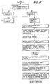
- FIG. 1 illustrates the step-by-step process for each 24-hour period.
- the accelerometer and minute volume sensors are constantly monitored.
- the accelerometer is active (above threshold) for one to 10 minute increments
- the minute volume sensor rate and minute volume ratio are collected for each of these increments and the respective averages of these two values are continuously updated throughout the 24-hour period.
- the peak minute volume sensor rate and peak minute volume ratio averages over one increment are saved, and, after resetting, the process is repeated for six additional 24-hour periods.
- the resulting seven daily peak minute volume sensor rates and minute volume ratio values are averaged.
- the pulsing rate response curve is adjusted a maximum of 4% of its range to thereby bring the averaged peak minute volume sensor values closer to 75% of the maximum pulsing rate. No pulsing rate response change is provided where the minute volume ratio is less than 1.2 or some other pre-programmed value.
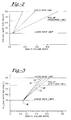
- Figure 2 illustrates graphically the relationship between pulsing rate and minute volume ratio value. As there shown, after the ratio reaches 1.2, the lower pulsing rate limit (shown here as 70 per minute) is affected. Because the target pulsing rate is 75% of the upper pulsing rate limit (here shown as 150 per minute), the minute volume ratio determines the pulsing rate delivered.
- Figure 3 also illustrates the relationship between pulsing rate and minute volume ratio, and additionally shows slope change as described above.
- line 10 shows a pre-set rate response gain factor or slope whereby, on an arbitrary scale of 0 to 5.0 which expresses minute volume ratio, 2.5 is chosen as the point where peak minute volume is at 75% of the upper pulsing rate per minute.
- Line 12 exemplifies an incremental adjustment to the initial setting of line 10, and represents a slope adjustment wherein the 75% pulsing rate velocity now has a value of 2.7.
- This 0.2 point change represents 4% of the minute volume sensor output range, with 0.2 point being the preferred change increment to be made after each seven day period where the peak average minute volume sensor rate output is below 75% of the upper pulsing rate limit.
- Line 14 exemplifies a subsequent adjustment which could occur seven days after the first slope adjustment occurs. It is to be noted that the point 18 of initial rise of the slope does not change, thereby keeping the rate increase threshold a constant.
- line 16 in the graph of Figure 3 exemplifies a decremental adjustment to the slope when a seven day peak minute volume sensor rate average exceeds 75% of the upper pulsing rate limit. While incremental changes of 0.2 point (4%) are preferred, as in line 12, decremental changes are preferably limited to 0.1 point (2%).
- Figure 4 illustrates an additional response characteristic which can be included as part of the preferred embodiment.
- This characteristic is a "bail out” feature which adjusts the pulsing rate to force a rapid change response if the minute volume sensor rate output remains above the upper pulsing rate limit for a pre-set length of time. In the preferred embodiment this length of time is 10 minutes.
- the pacemaker instrument is implanted in the patient according to standard procedures as known in the art to thereby apply stimulating pulses to cardiac tissue.
- minute volume sensor placement and minute volume activity data collection therefrom are as known in the art.
- the accelerometer is known in the art as is its data collection. Over a period of time, as described above, the pulsing rate provided by the instrument and as determined in view of minute volume sensor output and minute volume ratio is adjusted to approach an optimum level as required by each individual patient.
- gain factor or slope adjustment as described herein can be accomplished by utilizing output from the minute volume sensor means alone or the accelerometer output alone and still remain within the scope of the invention
- the preferred embodiment hereof utilizes input from both the accelerometer and minute volume sensor as above described to thereby improve specificity of pacing requirements.
- time increment variables as well as time period variables can be programmed as desired and as may be beneficial to a patient as determined by a physician.
Abstract
Description
- This invention relates in general to rate responsive cardiac pacemakers, and in particular to a pacemaker whose rate response gain factor or slope adjustment is automatically provided in relation to cardiac-related physiological characteristics of a patient.
- Rate response gain factor or slope adjustment is an important aspect in cardiac pacemaker operation as physiological consideration of a patient becomes more and more integrated with treatment modes. Further, because of the vagaries among patients, pre-set and solely manually adjustable arbitrary settings in a pacemaker device to regulate pulse delivery rates are not practical or in the best interest of the patient. Individual testing sessions for each patient, while perhaps desirable, are not practical because of time and money investments needed for such a program.
- It is, of course, obvious that increased patient activity requires increased pulsed delivery from a pacemaker. However, it is important that this increased pulse velocity have a physiological relationship to its need. Measurements that have cardiac relevance to pulse velocity requirements include minute volume, general patient activity which can be equivocated to accelerometer response in a so equipped pacemaker, right ventricle stroke volume, right ventricular pressure, blood oxygen level, central venous blood temperature, and the like.
- It is therefore a primary object of the present invention to provide a cardiac pacemaker which captures peak values of at least one cardiac-related physiological measurement over a consecutive preset number of time segments and then provides for automatic adjustment of the rate response slope.
- It is a further object of the present invention to provide a cardiac pacemaker which compares peak values of two separate physiological measurements wherein one such measurement must reach a preset threshold level before peak values of the other measurement are captured over a number of present time segments for use in pulsing rate adjustments.
- Another object of the present invention is to provide a cardiac pacemaker which compares minute volume measurements to patient activity measurements and captures peak minute volume levels coincident to significant patient activity levels as exemplified by accelerometer values exceeding a threshold level over a plurality of separate time segments.
- It is a further object of the present invention to provide a cardiac pacemaker which captures the minute volume ratios of each peak minute volume measurement and thereafter averages these ratios over the plurality of time segments.
- Yet another object of the present invention is to provide a cardiac pacemaker having control signal generating means for adjusting a rate response gain factor of the pacemaker such that peak minute volume ratios achieve a pre-determined heart-rate target value during periods of peak patient activity.
- These and other objects of the present invention will become apparent throughout the description which now follows.
- The present invention is a cardiac pacemaker having pulse generation means which include pulse rate control means that comprise, first of all, means for detecting a plurality of measurements of at least one cardiac-related physiological characteristic of a patient over each of a plurality of pre-determined periods of time, with each of the individual measurements being over respective multiple incremental periods of time occurring within each of the pre-determined periods of time. During each pre-determined period of time, only the data from one incremental period of time is saved, with such saved data being the highest average value obtained in an incremental period occurring over the pre-determined period. The pacemaker further comprises means for saving the highest measurement during each of the plurality of pre-determined periods of time. Means are present to thereafter average these saved measurements over a plurality of periods of time, after which control means adjust a rate responsive gain factor or slope of the stimulating pulses of the pacemaker in relation to the physiological characteristic base value and a pre-determined pacing target value for these averaged measurement values. Preferably, the pre-determined period of time is 24 hours, while each of the multiple incremental time periods within the 24-hour period is about one to 10 minutes, and the plurality of pre-determined periods of time over which averages are calculated is seven days. During each 24-hour period, only the averaged data from one incremental one-to-ten minute period is saved, with such saved data being the highest obtained in all of the incremental periods occurring over that 24-hour period. The preferred pre-determined target pacing rate derived from physiological characteristic values for the averaged measurements is about 75% of the upper pacing rate limit of the pacemaker. Rate response gain factor adjustments should be incrementally moderate, and preferably should be no more than about a four percent change per adjustment. Measured physiological characteristics can be chosen from the group consisting of minute volume, general patient activity as reflected by an accelerometer response, right ventricle stroke volume or pressure, blood oxygen level, central venous blood temperature, and the like.
- While only a single physiological characteristic can be measured for slope adjustment of the pacemaker, it is preferable to have two physiological characteristics simultaneously measured, with one of these measurements having a threshold level which must be reached before measurement values of the second characteristic are captured for subsequent averaging. Thus, in a preferred embodiment, the rate control means comprise, first of all, an accelerometer for detecting a plurality of individual activity level measurements of a patient as described above. Additional means are provided for detecting a plurality of individual minute volume ratio measurements coincidentally with the individual activity level measurements over identical incremental periods of time. The pacemaker further comprises means for saving the highest minute volume ratio measurement during each of the pre-determined time periods wherein the aforementioned activity level measurements exceed a pre-determined threshold value. Thus, when two physiological characteristics are measured, one of the characteristics can function as a gate or qualifier whose value must exceed a threshold magnitude before a measurement of the second physiological characteristic is captured and included in determining subsequent slope modification.
-
- Figure 1 is an operational flow chart of a pacemaker of the present invention;
- Figure 2 is a graph showing the relationship between pulsing rate per minute of the pacemaker of the present invention and minute volume ratio of a patient;
- Figure 3 is a graph similar to that of Figure 2 showing the relationship between pulsing rate per minute of the pacemaker of the present invention and minute volume ratio; and
- Figure 4 is an operational chart of the pacemaker of the present invention showing an alternate operation thereof related to excess minute volume values of a patient.
- The preferred embodiment of the present invention comprises a cardiac pacemaker which provides pulse generating rate control based upon an algorithm which correlates minute volume sensor values occurring simultaneously with accelerometer values to minute volume ratio values over increments of time within a finite period of time. In particular, the preferred pacemaker monitors minute volume (MV) and accelerometer (ACCEL) values constantly, and responds by saving the highest minute volume sensor rate over a one to 10 minute time increment occurring in a 24-hour period when the minute volume sensor rate is accompanied by accelerometer activity which denotes patient activity above the threshold value of the accelerometer. Thus, the preferred embodiment requires simultaneous heightened general activity and heightened minute volume value before minute volume value is analyzed for possible inclusion in a subsequent adjustment of pulsing rate. Increased accelerometer output level must be maintained for a minimum time, but less than a maximum time. In the preferred embodiment, this time span is between one and 10 minutes. Concurrent with the above is the computation of the minute volume ratio which is, of course, defined as current minute volume sensor value divided by minute volume base value. At the end of each 24-hour period, the pacemaker saves the highest or peak average minute volume sensor rate value and minute volume ratio value occurring during one one-to-ten minute increment of the 24-hour period, discards all other minute volume sensor rate and ratio values for the 24-hour period, and resets to repeat this 24 hour process. At the end of a seven day period, all of the peak values of the minute volume sensor rates and ratio values are averaged and the pacing rate response gain factor or slope is adjusted as required to more accurately reflect pacing demand and to achieve a preferred target pacing rate which may be set at 75% of the maximum pacing rate attainable. The 24-hour and seven day capture and computation process is continuously subsequently repeated to thereby continuously adjust pacing rate in relation to minute volume sensor rate as coupled with accelerometer activity.
- Reference is now made to Figure 1 which illustrates the step-by-step process for each 24-hour period. Specifically, throughout each 24-hour period, the accelerometer and minute volume sensors are constantly monitored. When the accelerometer is active (above threshold) for one to 10 minute increments, the minute volume sensor rate and minute volume ratio are collected for each of these increments and the respective averages of these two values are continuously updated throughout the 24-hour period. At the conclusion of the 24-hour period, the peak minute volume sensor rate and peak minute volume ratio averages over one increment are saved, and, after resetting, the process is repeated for six additional 24-hour periods. At the end of the seven days, the resulting seven daily peak minute volume sensor rates and minute volume ratio values are averaged. If the weekly sensor rate average is above or below 75% of the maximum pre-set pulsing rate of the pacemaker, the pulsing rate response curve is adjusted a maximum of 4% of its range to thereby bring the averaged peak minute volume sensor values closer to 75% of the maximum pulsing rate. No pulsing rate response change is provided where the minute volume ratio is less than 1.2 or some other pre-programmed value.
- Figure 2 illustrates graphically the relationship between pulsing rate and minute volume ratio value. As there shown, after the ratio reaches 1.2, the lower pulsing rate limit (shown here as 70 per minute) is affected. Because the target pulsing rate is 75% of the upper pulsing rate limit (here shown as 150 per minute), the minute volume ratio determines the pulsing rate delivered. Figure 3 also illustrates the relationship between pulsing rate and minute volume ratio, and additionally shows slope change as described above. In particular,
line 10 shows a pre-set rate response gain factor or slope whereby, on an arbitrary scale of 0 to 5.0 which expresses minute volume ratio, 2.5 is chosen as the point where peak minute volume is at 75% of the upper pulsing rate per minute.Line 12 exemplifies an incremental adjustment to the initial setting ofline 10, and represents a slope adjustment wherein the 75% pulsing rate velocity now has a value of 2.7. This 0.2 point change represents 4% of the minute volume sensor output range, with 0.2 point being the preferred change increment to be made after each seven day period where the peak average minute volume sensor rate output is below 75% of the upper pulsing rate limit.Line 14 exemplifies a subsequent adjustment which could occur seven days after the first slope adjustment occurs. It is to be noted that thepoint 18 of initial rise of the slope does not change, thereby keeping the rate increase threshold a constant. Finally,line 16 in the graph of Figure 3 exemplifies a decremental adjustment to the slope when a seven day peak minute volume sensor rate average exceeds 75% of the upper pulsing rate limit. While incremental changes of 0.2 point (4%) are preferred, as inline 12, decremental changes are preferably limited to 0.1 point (2%). - Figure 4 illustrates an additional response characteristic which can be included as part of the preferred embodiment. This characteristic is a "bail out" feature which adjusts the pulsing rate to force a rapid change response if the minute volume sensor rate output remains above the upper pulsing rate limit for a pre-set length of time. In the preferred embodiment this length of time is 10 minutes. When such a condition occurs, no matter at what point during the normal seven day data collection as shown in Figure 1, the gain factor slope is immediately reduced by 0.1 point (2%), all data for that seven day period is cleared, and a new seven day period, as exemplified at "start" in Figure 1, begins. In this manner, a rapid pacing response is imposed in response to a high rate from the minute volume sensor.
- In use, the pacemaker instrument is implanted in the patient according to standard procedures as known in the art to thereby apply stimulating pulses to cardiac tissue. Likewise, minute volume sensor placement and minute volume activity data collection therefrom are as known in the art. The accelerometer is known in the art as is its data collection. Over a period of time, as described above, the pulsing rate provided by the instrument and as determined in view of minute volume sensor output and minute volume ratio is adjusted to approach an optimum level as required by each individual patient. While it is to be understood that gain factor or slope adjustment as described herein can be accomplished by utilizing output from the minute volume sensor means alone or the accelerometer output alone and still remain within the scope of the invention, the preferred embodiment hereof utilizes input from both the accelerometer and minute volume sensor as above described to thereby improve specificity of pacing requirements. Concurrently, and likewise within the scope of the present invention, time increment variables as well as time period variables can be programmed as desired and as may be beneficial to a patient as determined by a physician.
- While an illustrative and presently preferred embodiment of the invention has been described in detail herein, it is to be understood that the inventive concepts may be otherwise variously embodied and employed and that the appended claims are intended to be construed to include such variation except insofar as limited by the prior art.
Claims (13)
- A cardiac pacemaker having a pulse generating means for applying stimulating pulses to cardiac tissue, the pulse generating means including means for controlling the rate at which said stimulating pulses are applied comprising:(a) means for establishing an upper pulsing rate limit;(b) detector means for detecting a plurality of individual measurements of an output of a physiologic sensor of at least a first cardiac-related physiological characteristic over each of a plurality of predetermined periods of time, with each of the individual measurements being an average of values detected over each of respective multiple incremental periods of time occurring within each of the predetermined periods of time;(c) saver means for saving a highest one of said measurements occurring during one incremental period of time in each of the plurality of predetermined periods of time;(d) averaging means for averaging the saved highest ones of said measurements over a plurality of periods of time to thereby yield an average physiological characteristic value;(e) adjuster means for adjusting, if necessary, a rate response gain factor of the stimulating pulses of the pacemaker in relation to a predetermined physician specified target pulse rate for the averaged physiological characteristic value; and(f) resetting means responsive to operation of said adjuster means for clearing the detector means, saver means and averaging means.
- A cardiac pacemaker according to Claim 1 wherein the physiological characteristics are selected from minute volume, general patient activity as reflected by an accelerometer response, right ventricle stroke volume, right ventricle pressure, blood oxygen level and central venous blood temperature.
- A cardiac pacemaker according to Claim 1 including further detector means for detecting a plurality of individual measurements of a second physiological characteristic over each of a plurality of predetermined periods of time, with each of the individual measurements being an average of values detected over each of respective multiple incremental periods of time occurring within each of the predetermined periods of time, and with each of the measurements being performed coincidentally with the measurement of the first physiological characteristic over the same incremental period of time when the measurement of the first physiological characteristic is above a predetermined threshold.
- A cardiac pacemaker according to Claim 1, 2 or 3 including an activation means which activates the adjuster means immediately when said measured cardiac-related physiological characteristic has a sensor rate output exceeding the upper pulsing rate limit for a predetermined length of time, with said adjuster means immediately reducing the rate responsive gain factor a predetermined magnitude.
- A cardiac pacemaker having a pulse generating means for applying stimulating pulses to cardiac tissue, the pulse generating means including means for controlling the rate at which said stimulating pulses are applied comprising:(a) means for establishing an upper pulsing rate limit;(b) first detection means for detecting a plurality of individual values of an output of a sensor of individual activity level measurements of a patient over each of a plurality of predetermined periods of time, with each of the individual level measurements being an average of values detected over each of respective multiple incremental periods of time occurring within each of the predetermined periods of time;(c) second detection means for detecting a plurality of individual values of a sensor of individual minute volume measurements of the patient over each of a plurality of predetermined periods of time, with each of the minute volume measurements being an average of values detected over each of respective multiple incremental periods of time occurring within each of the predetermined periods of time, and with each of the minute volume measurements being performed coincidentally with the individual activity level measurements over the same incremental period of time when said first detection means indicates an activity level that is above a predetermined threshold activity level;(d) saver means for saving the highest minute volume measurement occurring during one incremental period of time in each of the plurality of predetermined periods of time;(e) averaging means for determining a minute volume sensor rate value and a minute volume ratio for each of said highest minute volume measurements saved by said saver means and thereafter averaging these minute volume ratios over a plurality of periods of time, said minute volume ratio being a sensed minute volume measurement divided by a minute volume base value;(f) adjuster means for adjusting a rate response gain factor of the stimulating pulses of the pacemaker in relation to said minute volume sensor rate value and a physician-specified target value of a minute volume sensor rate value for these averaged minute volume ratios; and(g) resetting means responsive to the operation of said adjuster means for clearing the first and second detection means, saver means and averaging means.
- A cardiac pacemaker according to Claim 5 wherein the first detecting means is an accelerometer.
- A cardiac pacemaker according to Claim 5 including an activation means which activates the adjuster means immediately when the sensor rate output of the minute volume measurements exceed the upper pulsing rate limit for a predetermined length of time, with said adjuster means immediately reducing the rate responsive gain factor a predetermined magnitude.
- A cardiac pacemaker according to any preceding claim wherein the predetermined period of time is 24 hours.
- A cardiac pacemaker according to any preceding claim wherein the incremental period of time is between about one and 10 minutes.
- A cardiac pacemaker according to any preceding claim wherein the plurality of predetermined periods of time is seven days.
- A cardiac pacemaker according to any preceding claim wherein said target is substantially about 75% of said upper rate pulsing limit of the pacemaker.
- A cardiac pacemaker according to Claim 4 or 7 wherein the predetermined length of time is 10 minutes.
- A cardiac pacemaker according to Claim 12 wherein the rate responsive gain factor is reduced about two percent.
Applications Claiming Priority (2)
| Application Number | Priority Date | Filing Date | Title |
|---|---|---|---|
| US155482 | 1993-11-22 | ||
| US08/155,482 US5423870A (en) | 1993-11-22 | 1993-11-22 | Rate responsive cardiac pacemaker |
Publications (2)
| Publication Number | Publication Date |
|---|---|
| EP0654285A2 true EP0654285A2 (en) | 1995-05-24 |
| EP0654285A3 EP0654285A3 (en) | 1997-09-10 |
Family
ID=22555615
Family Applications (1)
| Application Number | Title | Priority Date | Filing Date |
|---|---|---|---|
| EP94307331A Withdrawn EP0654285A3 (en) | 1993-11-22 | 1994-10-06 | Rate responsive cardiac pacemaker. |
Country Status (5)
| Country | Link |
|---|---|
| US (1) | US5423870A (en) |
| EP (1) | EP0654285A3 (en) |
| JP (1) | JPH07194712A (en) |
| AU (1) | AU7434994A (en) |
| CA (1) | CA2133005C (en) |
Cited By (4)
| Publication number | Priority date | Publication date | Assignee | Title |
|---|---|---|---|---|
| DE19609382A1 (en) * | 1996-03-04 | 1997-09-11 | Biotronik Mess & Therapieg | Activity-controlled pacemaker |
| EP0804939A2 (en) * | 1996-04-29 | 1997-11-05 | Pacesetter, Inc. | Using MV to classify patient cardiac condition in an implanted device |
| EP0933095A2 (en) | 1998-01-29 | 1999-08-04 | BIOTRONIK Mess- und Therapiegeräte GmbH & Co Ingenieurbüro Berlin | Auto-calibrating rate adaptive pacemaker |
| EP0966987A1 (en) * | 1998-06-26 | 1999-12-29 | ELA MEDICAL (Société anonyme) | Multi-site, parameter controlled, implantable pacemaker / defibrillator |
Families Citing this family (23)
| Publication number | Priority date | Publication date | Assignee | Title |
|---|---|---|---|---|
| DE4231603A1 (en) * | 1992-09-17 | 1994-03-24 | Biotronik Mess & Therapieg | Pacemaker system |
| WO1996040337A1 (en) * | 1995-06-07 | 1996-12-19 | Nellcor Puritan Bennett Incorporated | Pressure control for constant minute volume |
| SE9502430D0 (en) * | 1995-07-04 | 1995-07-04 | Pacesetter Ab | Device for varying the threshold detection level of a sensor |
| US5978711A (en) * | 1998-02-23 | 1999-11-02 | Vivatron Medical, B.V. | Pacemaker system with improved learning capability for adapting rate response function |
| US6076015A (en) * | 1998-02-27 | 2000-06-13 | Cardiac Pacemakers, Inc. | Rate adaptive cardiac rhythm management device using transthoracic impedance |
| US6314322B1 (en) | 1998-03-02 | 2001-11-06 | Abiomed, Inc. | System and method for treating dilated cardiomyopathy using end diastolic volume (EDV) sensing |
| US6411850B1 (en) | 1999-09-30 | 2002-06-25 | Uab Research Foundation | Method of determining a ventilatory threshold breakpoint for an adaptive rate pacemaker |
| US6522914B1 (en) * | 2000-07-14 | 2003-02-18 | Cardiac Pacemakers, Inc. | Method and apparatuses for monitoring hemodynamic activities using an intracardiac impedance-derived parameter |
| US6519495B1 (en) * | 2000-08-15 | 2003-02-11 | Cardiac Pacemakers, Inc. | Rate-adaptive therapy with sensor cross-checking |
| US6823214B1 (en) | 2000-09-08 | 2004-11-23 | Cardiac Pacemakers, Inc. | Self-calibrating rate-adaptive pacemaker |
| US7069070B2 (en) * | 2003-05-12 | 2006-06-27 | Cardiac Pacemakers, Inc. | Statistical method for assessing autonomic balance |
| US6990375B2 (en) * | 2001-03-02 | 2006-01-24 | Cardiac Pacemakers, Inc. | Adjustment of the breakpoint of the rate response curve based on minute ventilation values |
| US7215992B2 (en) * | 2001-10-31 | 2007-05-08 | Cardiac Pacemakers, Inc. | Method for ischemia detection by implantable cardiac device |
| US7050854B2 (en) | 2002-06-24 | 2006-05-23 | Cardiac Pacemakers, Inc. | Calibration of adaptive-rate pacing using intrinsic chronotropic response |
| US7092757B2 (en) | 2002-07-12 | 2006-08-15 | Cardiac Pacemakers, Inc. | Minute ventilation sensor with dynamically adjusted excitation current |
| US7101339B2 (en) * | 2002-12-13 | 2006-09-05 | Cardiac Pacemakers, Inc. | Respiration signal measurement apparatus, systems, and methods |
| US8050764B2 (en) | 2003-10-29 | 2011-11-01 | Cardiac Pacemakers, Inc. | Cross-checking of transthoracic impedance and acceleration signals |
| US7272442B2 (en) | 2002-12-30 | 2007-09-18 | Cardiac Pacemakers, Inc. | Automatically configurable minute ventilation sensor |
| US7200440B2 (en) | 2003-07-02 | 2007-04-03 | Cardiac Pacemakers, Inc. | Cardiac cycle synchronized sampling of impedance signal |
| US7392084B2 (en) | 2003-09-23 | 2008-06-24 | Cardiac Pacemakers, Inc. | Demand-based cardiac function therapy |
| US7572226B2 (en) * | 2003-10-28 | 2009-08-11 | Cardiac Pacemakers, Inc. | System and method for monitoring autonomic balance and physical activity |
| US8406879B2 (en) | 2006-12-20 | 2013-03-26 | Cardiac Pacemakers, Inc. | Rate adaptive cardiac pacing systems and methods |
| US11707628B2 (en) * | 2019-05-30 | 2023-07-25 | Medtronic, Inc. | Rate responsive pacing |
Citations (4)
| Publication number | Priority date | Publication date | Assignee | Title |
|---|---|---|---|---|
| US4702253A (en) * | 1985-10-15 | 1987-10-27 | Telectronics N.V. | Metabolic-demand pacemaker and method of using the same to determine minute volume |
| US5031614A (en) * | 1986-09-12 | 1991-07-16 | Eckhard Alt | Pacemaker rate control using amplitude and frequency of activity signal |
| WO1992003182A1 (en) * | 1990-08-14 | 1992-03-05 | Medtronic, Inc. | Rate responsive pacemaker and methods for optimizing its operation |
| WO1993020889A1 (en) * | 1992-04-17 | 1993-10-28 | Medtronic, Inc. | Method and apparatus for rate-responsive cardiac pacing |
Family Cites Families (5)
| Publication number | Priority date | Publication date | Assignee | Title |
|---|---|---|---|---|
| DE3419439C1 (en) * | 1984-05-24 | 1985-11-21 | Eckhard Dr. 8000 München Alt | Frequency-dependent pacemaker depending on the load |
| DE3732640C1 (en) * | 1987-09-28 | 1989-05-18 | Alt Eckhard | Medical device for determining physiological functional parameters |
| GB2214813A (en) * | 1988-01-14 | 1989-09-13 | Stuart Charles Webb | Rate-responsive pacemaker |
| US4945909A (en) * | 1989-06-06 | 1990-08-07 | Cook Pacemaker Corporation | Pacemaker with activity-dependent rate limiting |
| US5088488A (en) * | 1989-12-22 | 1992-02-18 | Medtronic, Inc. | Method and apparatus for implementing histogram storage and trend analysis in a medical stimulator |
-
1993
- 1993-11-22 US US08/155,482 patent/US5423870A/en not_active Expired - Lifetime
-
1994
- 1994-09-27 CA CA002133005A patent/CA2133005C/en not_active Expired - Fee Related
- 1994-09-29 AU AU74349/94A patent/AU7434994A/en not_active Abandoned
- 1994-10-06 EP EP94307331A patent/EP0654285A3/en not_active Withdrawn
- 1994-11-22 JP JP6288247A patent/JPH07194712A/en active Pending
Patent Citations (4)
| Publication number | Priority date | Publication date | Assignee | Title |
|---|---|---|---|---|
| US4702253A (en) * | 1985-10-15 | 1987-10-27 | Telectronics N.V. | Metabolic-demand pacemaker and method of using the same to determine minute volume |
| US5031614A (en) * | 1986-09-12 | 1991-07-16 | Eckhard Alt | Pacemaker rate control using amplitude and frequency of activity signal |
| WO1992003182A1 (en) * | 1990-08-14 | 1992-03-05 | Medtronic, Inc. | Rate responsive pacemaker and methods for optimizing its operation |
| WO1993020889A1 (en) * | 1992-04-17 | 1993-10-28 | Medtronic, Inc. | Method and apparatus for rate-responsive cardiac pacing |
Cited By (11)
| Publication number | Priority date | Publication date | Assignee | Title |
|---|---|---|---|---|
| DE19609382A1 (en) * | 1996-03-04 | 1997-09-11 | Biotronik Mess & Therapieg | Activity-controlled pacemaker |
| US6263243B1 (en) | 1996-03-04 | 2001-07-17 | Biotronik Mess-Und Therapiegeraete Gmbh & Co. Ingenieurbuero Berlin | Rate adaptive pacemaker |
| EP0804939A2 (en) * | 1996-04-29 | 1997-11-05 | Pacesetter, Inc. | Using MV to classify patient cardiac condition in an implanted device |
| EP0804939A3 (en) * | 1996-04-29 | 1998-09-30 | Pacesetter, Inc. | Using MV to classify patient cardiac condition in an implanted device |
| EP0933095A2 (en) | 1998-01-29 | 1999-08-04 | BIOTRONIK Mess- und Therapiegeräte GmbH & Co Ingenieurbüro Berlin | Auto-calibrating rate adaptive pacemaker |
| DE19804843A1 (en) * | 1998-01-29 | 1999-08-05 | Biotronik Mess & Therapieg | Self-calibrating rate-adaptive pacemaker |
| EP0933095A3 (en) * | 1998-01-29 | 2000-01-19 | BIOTRONIK Mess- und Therapiegeräte GmbH & Co Ingenieurbüro Berlin | Auto-calibrating rate adaptive pacemaker |
| US6154674A (en) * | 1998-01-29 | 2000-11-28 | Biotronik Mess-Und Therapiegeraete Gmbh & Co. Ingenieurbuero Berlin | Self-calibrating adaptive-rate cardiac pacemaker |
| EP0966987A1 (en) * | 1998-06-26 | 1999-12-29 | ELA MEDICAL (Société anonyme) | Multi-site, parameter controlled, implantable pacemaker / defibrillator |
| FR2780290A1 (en) * | 1998-06-26 | 1999-12-31 | Ela Medical Sa | ACTIVE ACTIVE IMPLANTABLE MEDICAL DEVICE SUCH AS A CARDIAC STIMULATOR, DEFIBRILLATOR AND / OR CARDIOVERVER, ESPECIALLY OF THE MULTI-SITE TYPE |
| US6246910B1 (en) | 1998-06-26 | 2001-06-12 | Ela Medical S.A. | Rate responsive active implantable medical device such as a pacemaker, defibrillator and/or cardiovertor, including the multisite type |
Also Published As
| Publication number | Publication date |
|---|---|
| EP0654285A3 (en) | 1997-09-10 |
| CA2133005A1 (en) | 1995-05-23 |
| US5423870A (en) | 1995-06-13 |
| CA2133005C (en) | 2001-03-20 |
| AU7434994A (en) | 1995-06-01 |
| JPH07194712A (en) | 1995-08-01 |
Similar Documents
| Publication | Publication Date | Title |
|---|---|---|
| US5423870A (en) | Rate responsive cardiac pacemaker | |
| US4966146A (en) | Rate-responsive pacemaker | |
| EP0545971B1 (en) | Pacemaker with optimized rate responsiveness | |
| US5674254A (en) | Cardiac pacemaker system and method for determining a measure of pacing threshold without incurring loss of capture | |
| US5365932A (en) | Cardiac signal sensing device having sensitivity automatically controlled in response to metabolic demand | |
| EP1177014B1 (en) | Adaptive evoked response sensing for automatic capture verification | |
| EP0361517B1 (en) | Rate adaptive cardiac pacemaker system | |
| US6263243B1 (en) | Rate adaptive pacemaker | |
| JP2562800B2 (en) | A rate-responsive cardiac pacemaker that provides an optimized pacing rate that varies with the patient's physiological demand | |
| EP0510456B1 (en) | Implantable medical apparatus | |
| EP0596598A2 (en) | Cardiac rhythm management device with automatic optimization of performance related pacing parameters | |
| US5741312A (en) | Pacemaker system and method with improved capture detection and threshold search | |
| US7974708B2 (en) | Calibration of adaptive-rate pacing using intrinsic chronotropic response | |
| CA2088241A1 (en) | Rate controlled pacemaker system using ar internal for rate control | |
| EP1483018A1 (en) | Technique for blood pressure regulation | |
| EP0426775B1 (en) | Automatically adjustable energy controlled rate-responsive pacemaker | |
| US6119040A (en) | Cardiac pacemaker upper rate limit control | |
| US5978711A (en) | Pacemaker system with improved learning capability for adapting rate response function | |
| EP0759313A2 (en) | Device for varying the threshold detection level of a sensor | |
| EP0148486B1 (en) | Improved rate adaptive pacemaker apparatus | |
| EP1051992B1 (en) | Rate responsive pacemaker with improved rate change dynamics | |
| EP0616819B1 (en) | Rate-responsive pacemaker | |
| US11433239B2 (en) | Active implantable medical device for the treatment of heart failure with vagus nerve stimulation | |
| US5271396A (en) | Activity controlled pacer with automatic sensor response amplification adjustment | |
| Baig et al. | One‐year follow‐up of automatic adaptation of the rate response algorithm of the QT sensing, rate adaptive pacemaker |
Legal Events
| Date | Code | Title | Description |
|---|---|---|---|
| PUAI | Public reference made under article 153(3) epc to a published international application that has entered the european phase |
Free format text: ORIGINAL CODE: 0009012 |
|
| AK | Designated contracting states |
Kind code of ref document: A2 Designated state(s): DE FR GB IT NL |
|
| PUAL | Search report despatched |
Free format text: ORIGINAL CODE: 0009013 |
|
| AK | Designated contracting states |
Kind code of ref document: A3 Designated state(s): DE FR GB IT NL |
|
| 17P | Request for examination filed |
Effective date: 19980226 |
|
| 17Q | First examination report despatched |
Effective date: 20010110 |
|
| STAA | Information on the status of an ep patent application or granted ep patent |
Free format text: STATUS: THE APPLICATION IS DEEMED TO BE WITHDRAWN |
|
| 18D | Application deemed to be withdrawn |
Effective date: 20010711 |