EP0654224A2 - Device for treating a strip of filter material - Google Patents
Device for treating a strip of filter material Download PDFInfo
- Publication number
- EP0654224A2 EP0654224A2 EP94117723A EP94117723A EP0654224A2 EP 0654224 A2 EP0654224 A2 EP 0654224A2 EP 94117723 A EP94117723 A EP 94117723A EP 94117723 A EP94117723 A EP 94117723A EP 0654224 A2 EP0654224 A2 EP 0654224A2
- Authority
- EP
- European Patent Office
- Prior art keywords
- section
- strip
- arrangement according
- stretching
- application
- Prior art date
- Legal status (The legal status is an assumption and is not a legal conclusion. Google has not performed a legal analysis and makes no representation as to the accuracy of the status listed.)
- Granted
Links
Images

Classifications
-
- A—HUMAN NECESSITIES
- A24—TOBACCO; CIGARS; CIGARETTES; SIMULATED SMOKING DEVICES; SMOKERS' REQUISITES
- A24D—CIGARS; CIGARETTES; TOBACCO SMOKE FILTERS; MOUTHPIECES FOR CIGARS OR CIGARETTES; MANUFACTURE OF TOBACCO SMOKE FILTERS OR MOUTHPIECES
- A24D3/00—Tobacco smoke filters, e.g. filter-tips, filtering inserts; Filters specially adapted for simulated smoking devices; Mouthpieces for cigars or cigarettes
- A24D3/02—Manufacture of tobacco smoke filters
- A24D3/0204—Preliminary operations before the filter rod forming process, e.g. crimping, blooming
- A24D3/0212—Applying additives to filter materials
-
- A—HUMAN NECESSITIES
- A24—TOBACCO; CIGARS; CIGARETTES; SIMULATED SMOKING DEVICES; SMOKERS' REQUISITES
- A24D—CIGARS; CIGARETTES; TOBACCO SMOKE FILTERS; MOUTHPIECES FOR CIGARS OR CIGARETTES; MANUFACTURE OF TOBACCO SMOKE FILTERS OR MOUTHPIECES
- A24D3/00—Tobacco smoke filters, e.g. filter-tips, filtering inserts; Filters specially adapted for simulated smoking devices; Mouthpieces for cigars or cigarettes
- A24D3/02—Manufacture of tobacco smoke filters
- A24D3/0204—Preliminary operations before the filter rod forming process, e.g. crimping, blooming
Definitions
- the invention relates to an arrangement for processing at least one strip of filter material for the tobacco processing industry, which is taken from a supply and fed to a stretching section with a stretching device, which is followed by an application section with an application device for applying application liquid that dissolves the filter material onto the strip, which in turn a shirring section with a shirring device reducing the width of the strip is arranged downstream.
- a strip of filter material, so-called filter tow of interconnected fibers, e.g. B. from cellulose acetate, continuously from a supply, for. B. from a bale, peeled, spread, stretched, with a solvent, e.g. B. triazetine, sprayed, gathered laterally, a nozzle charged with blown air and then fed to a funnel, from which the prepared and compressed filter strip is fed to a filter rod machine.
- the strip formed into a filter strand is continuously covered with a covering material strip with further compression, after which filter rods are cut off from the covered filter strand.
- Proven processing devices of the type described above are manufactured and sold by the applicant under the designations AF 1, AF 2 and AF 3.
- Proven filter rod machines of the type described are built and sold by the applicant under the designations KDF 2 and KDF 3.
- the problem underlying the invention is to create a further advantageous processing arrangement for filter tow.
- the solution according to the invention is that the stretching section, the application section and the gathering section form at least approximately the shape of a U or a V.
- the stretching section which advantageously comprises at least two pairs of stretching rolls with different peripheral speeds, can have a length of 800 mm to 1200 mm, preferably 1000 mm. It has surprisingly been found that such a length gives optimal values with regard to the tow yield (tow amount per unit length with constant tensile resistance in the finished filter rod).
- the width of the filter strip in the stretching section and the application section can preferably be 120 mm to 150 mm. With such a small width, two or more filter tow strips simultaneously drawn off from bales and guided in parallel can be prepared relatively easily, for which purpose the same processing devices can predominantly be used. If the filter strand machine is then designed to process two filter tow strips simultaneously to encased filter strands (so-called two-strand machine), the production performance of a treatment plant can be increased significantly without major additional mechanical expenditure.
- the stretching section can be arranged at least approximately vertically or with a predominantly vertical component with a preferred conveying of the strip from top to bottom.
- the Application device can be arranged in the preferably at least approximately horizontally arranged application section and can be designed as a spray device spraying the filter tow from both sides after releasing it from stretching with finely divided liquid such as triazetin to dissolve the filter tow fibers.
- the gathering section can be arranged at least approximately vertically or with a predominantly vertical component with a preferred conveying direction of the filter tow strip from bottom to top.
- the gathering section and stretching section can have at least approximately the same length.
- the stretching section as well as the application section and the gathering section are arranged in the form of a V
- the stretching section can form one leg of the V, preferably with a strip conveyor running from top to bottom, while the application section and the immediately following gathering section, with the opposite conveying direction, form the other leg of the V form.
- the actual stretching section can be preceded by a pre-stretching section, the conveying direction of the filter tow strip, which preferably runs from top to bottom, can have a vertical and a horizontal component.
- a conditioning device for conditioning the filter tow strip to a constant relative humidity preferably a drying device, can be arranged in an advantageous, independent inventive rank of the invention.
- B. can be designed as an infrared heater.
- the beginning of the stretching section can be a preferably non-drivable pair of rolls, the rolls of which can be pressed against one another with controllable force, while at the end of the stretching section the first pair of rolls of the actual stretching section can be arranged.
- the direction of the filter tow strip reversing roller pairs of stretching and application section can each z.
- a pneumatic spreading nozzle can be arranged upstream of the stretching section, from which blown air emerges for spreading the filter tow fibers.
- the application device can be provided with a charging device for applying electrostatic charges to the filter tow strip. This improves the separation of the fibers of the filter tow strip and makes spraying more uniform, especially when the droplets of the dissolving liquid receive charges with opposite polarity to the charges on the filter tow strip.
- the application device can advantageously be followed by a discharge device designed as an ionization device.
- the above-mentioned conditioning device preferably in the form of a drying device, can be controlled by a control arrangement in order to achieve a constant relative humidity in the filter tow strip, to which a measurement signal can be fed from a moisture measurement device.
- the measuring device can be a device for detecting a field strength resulting from electrostatic charges on the filter tow strip.
- the electrostatic charge can e.g. B. generated by the stretching of the filter tow strip.
- the tow yield can be increased considerably and a filter tow saving of several percent with the same tensile resistance of the filter rods produced with the processed filter tow can be achieved -
- the dimensions of the processing plant can be reduced;
- the "depth" of the system can be reduced to such an extent that several filter tow strips can be processed simultaneously.
- the draw-off section 3, in which the filter material strip 2a is conveyed along the arrow 5, has one or more spreader nozzles 16 which receive compressed air from a compressed air source 17.
- the compressed air serves to spread the filter tow fabric conveyed in the direction of arrow 5 in section 2a.
- a - controllable - spreader nozzle is described in US-A-4,259,769.
- the filter tow strip reaches the pre-stretch section 4 via deflection rollers 18, 19, which is delimited on the one hand by a pair of rollers 21 with the rollers 22, 23 and on the other hand by a pair of rollers 24 with motor-driven rollers 26, 27 - the rollers 22, 23 are separated by the tow strip 2b towed, ie they run empty with more or less resistance. If necessary, they can be driven by a motor. They can also be pressed against one another in a manner known per se with controllable force.
- the filter tow is pre-stretched in the pre-stretching section in which the strip section 2b is conveyed obliquely downwards in the direction of the arrow 28.
- a conditioning device 29 which is designed as a controllable drying device 31.
- the filter tow is conditioned in a controlled manner to a predetermined, preferably constant, relative humidity (water).
- a suitable drying device 31 is sold under the name WEKO-HEAT dryer by HAUG GmbH & Co. KG, PO Box 200333, D-70771 Leinfelden-Echterdingen.
- a speed sensor 32 known per se which detects the speed of the filter strip 2b directly or indirectly, for example in a known manner via the speed of the motor-driven roller pair 24, outputs a signal dependent on the speed of the strip section 2b to an input a of a control arrangement 33, which controls an electrical energy source 34 for the drying device 31 by means of a signal at an output d such that the heating power increases when the speed of the strip section 2b increases, and decreases when the speed decreases.
- the signals supplied to the inputs b and c of the control arrangement 33 will be explained later.
- Downstream of the drying device 31 is a charging rod 37 for applying electrostatic charges to the filter tow strip.
- the rod sold by the aforementioned company HAUG with the type designation ALS A 030-500 can be used with the charger 38 AG-3 neg / 7612 and AG-3 pos / 7609.
- the electrostatic charges of high potential applied to the strip section 2b ensure good separation of the individual fibers of the filter tow strip still adhering to one another by means of electrostatic repulsion forces, which is advantageous for the subsequent application of solvent droplets to the filter tow strip. Details of the application of electrostatic charges can be found in US-A-3 817 211 and the US defensive publication 665,476, U.S. Official Gazette 860/3 dated March 18, 1969.
- the actual stretching section 6 adjoins the pair of rolls 24, in which section 2c of the filter tow strip is conveyed vertically or with a vertical component according to arrow 36 from top to bottom.
- a further pair of rollers 39 made of motor-driven rollers 41, 42, the peripheral speeds of which are somewhat greater than the peripheral speeds of the rollers 26, 27, so that the elastic filter tow is stretched in a defined manner in section 2c.
- the roller pairs 24 and 39 thus form the actual stretching device.
- Rollers 26 and 41 have a rigid grooved surface each touching a resilient surface of rollers 27 and 42, respectively.
- Such roller configurations are known from the aforementioned filter tow processing devices AF 1, AF 2 and AF 3 from the applicant and z.
- the length c of the stretching section can be between 800 mm and 1200 mm, preferably about 1000 mm. It has been shown that, surprisingly, a particularly good tow yield can be achieved in this length range.
- the pair of rollers 39 is followed by a further pair of rollers 43 made of motor-driven rollers 44, 46, the peripheral speeds of which are lower than those of the rollers 41, 42, so that the filter tow relaxes slightly in section 2d when it is conveyed in accordance with arrow 49.
- the pair of rollers 43 again has a roller 44 with a rigid grooved surface which is in contact with the resilient surface of the roller 46.
- Limit the pairs of rollers 39 and 43 thus the at least approximately horizontally arranged application section 7, in which an application device 47 in the form of a spraying device 48 is arranged.
- the spraying device 48 can be designed as described in US Pat. No.
- the width of the filter tow strip in the stretching section 6 and the application section 7 is preferably between 120 mm and 150 mm. This is such a small width that it allows processing devices for two filter tow strips guided in parallel to be arranged one behind the other perpendicular to the plane of the drawing and thus to be used twice. The strips can then be processed into filter rods in a filter strand machine that processes two strands simultaneously.
- the gathering section 8 Downstream of the application section is the gathering section 8, in which section 2e of the filter tow strip is conveyed vertically or with a predominantly vertical component (as shown) by a pair of rolls 51 with motor-driven rolls 52, 53 from bottom to top in the direction of arrow 54.
- the roller 52 again has a rigid grooved surface
- the contact roller 53 has a resilient surface.
- gathering devices in the form of wire loops 56a ... 56c are arranged which constantly reduce the width of the filter tow in section 2e.
- the wire loops have different, ie, decreasing, dimensions.
- a moisture measuring device 57 in the form of a measuring device 58 for the field strength, which is caused by electrostatic charges which are located on the filter tow strip.
- This electrostatic Charges originate from stretching in stretching section 6. Additional charges, as described with the aid of the charging rod 37, are not expedient when the field strength is detected as the moisture measurement value of the filter material.
- the field strength is a measure of the content of water in the fibers of the filter tow.
- a corresponding output signal is fed to a comparison element 59 and compared there with a setpoint value output by a setpoint generator 61.
- the output signal of the comparator 59 acts on the input b of the control arrangement 33, the input c of which receives a signal from a temperature sensor 62 on the drying device 31.
- This advantageous development of the invention also has an independent inventive rank.
- the feed section 9 Downstream of the pair of deflecting rollers 51 is the feed section 9, in which section 2f of the filter tow strip is conveyed in the direction of arrow 62 and is freed of adhering electrostatic charges which are disadvantageous for further processing by means of a discharge device 63.
- It is an ionizing device in the form of ring electrodes 64a, 64b, as it is sold by the aforementioned company HAUG under the type designation EI-RE 014-200 with the power pack 66 under the type designation EN-7/7703.
- the feed section 9 there is also a driven deflection roller 67 with a rounded groove 68 on the circumference rotating at the filter tow speed and a so-called stuffing nozzle 69, known per se, to which compressed air is supplied from an appealing compressed air source 71.
- 72 is an inlet funnel and 12 the filter rod machine.
- the stretching section 6, application section 7 and gathering section 8 form at least approximately a U, the inclination of the gathering section in the direction of the stretching section being even greater than shown.
- a filter tow strip 2 is pulled off the bale 1 and first spread out in section 2a.
- the filter strip is first pre-stretched by the roller pairs 21 and 24, its relative humidity (water) being kept at a constant value by the drying device 31.
- the fibers of the filter tow strip are stretched by the rollers of the roller pairs 24 and 39 rotating at different peripheral speeds, with the roller pair 39 being the greater peripheral speed Has.
- the fibers of the filter tow strip are relaxed by the rollers of the roller pairs 39 and 43 rotating at different speeds because the roller pair 43 has a lower peripheral speed than the roller pair 39.
- B. Triazetin Triazetin.
- the filter tow strip which is conveyed by the roller pairs 51 and 43, is gathered by the wire loops 56a ... 56c, the width of which decreases in each case, ie the width perpendicular to the plane of the drawing is reduced.
- the moisture is detected by the measuring device 58 and a corresponding measuring signal is sent to the control arrangement 33 for the drying device 31.
- the filter material is passed through the ionizer 64a, 64b freed of its electrostatic charges and, after deflection on the roller 68, fed to the funnel 72 and the inlet 11 of the filter rod machine 12 via the stuffing nozzle 69.
- the stretching section 6 forms one leg of a V, while the application section 7 and the gathering section 8 form the other leg.
- the stretching section 6 is formed by the two motor-driven roller pairs 24 and 39.
- Their length c is also preferably between 800 mm and 1200 mm, advantageously 1000 mm.
- the application device 47 has a spraying device 48 which contains rapidly rotating rotors 50 which spray the supplied solution liquid in the form of thin spray threads 55 onto the filter tow 2d.
- Such application devices are sold by Weitmann & Konrad GmbH & Co. KG, Postfach 200252, D-70771 Leinfelden-Echterdingen, under the name WEKO-ROTORENBEFEUCHTUNG für MATERIALBAHNEN.
- the shirring section 8 directly adjoins the application section 7 with its wire loops 56a ... 56c, which ends at the pair of rollers 51.
- the plant sections upstream of the stretching section 6 and those downstream of the application section 7 and the gathering section 8 can be designed as described in FIG. 1.
Abstract
Description
Die Erfindung betrifft eine Anordnung zum Aufbereiten mindestens eines Streifens aus Filtermaterial für die tabakverarbeitende Industrie, der einem Vorrat entnommen und einer Reckstrecke mit einer Reckeinrichtung zugeführt wird, der eine Auftragstrecke mit einer Auftrageinrichtung zum Auftragen von das Filtermaterial anlösender Auftragflüssigkeit auf den Streifen nachgeordnet ist, der wiederum eine Raffstrecke mit einer die Breite des Streifens vermindernden Raffeinrichtung nachgeordnet ist.The invention relates to an arrangement for processing at least one strip of filter material for the tobacco processing industry, which is taken from a supply and fed to a stretching section with a stretching device, which is followed by an application section with an application device for applying application liquid that dissolves the filter material onto the strip, which in turn a shirring section with a shirring device reducing the width of the strip is arranged downstream.
Zum Herstellen von Filterstäben für die tabakverarbeitende Industrie wird ein Streifen aus Filtermaterial, sogenanntes Filtertow, aus miteinander verbundenen Fasern, z. B. aus Zelluloseazetat, fortlaufend von einem Vorrat, z. B. von einem Ballen, abgezogen, ausgebreitet, gereckt , mit einem Lösungsmittel, z. B. Triazetin, besprüht, seitlich gerafft, einer mit Blasluft beaufschlagten Düse und anschließend einem Trichter zugeführt, von dem aus der aufbereitete und verdichtete Filterstreifen einer Filterstrangmaschine zugeführt wird. In der Filterstrangmaschine wird der zu einem Filterstrang geformte Streifen unter weiterer Verdichtung fortlaufend mit einem Hüllmaterialstreifen umhüllt, wonach von dem umhüllten Filterstrang Filterstäbe abgeschnitten werden.
Bewährte Aufbereitungsgeräte der vorbeschriebenen Art werden unter der Bezeichnung AF 1, AF 2 und AF 3 von der Anmelderin gebaut und vertrieben. Bewährte Filterstrangmaschinen der beschriebenen Art werden unter der Bezeichnung KDF 2 und KDF 3 von der Anmelderin gebaut und vertrieben. Das der Erfindung zugrundeliegende Problem besteht darin, eine weitere vorteilhafte Aufbereitungsanordnung für Filtertow zu schaffen.To produce filter rods for the tobacco processing industry, a strip of filter material, so-called filter tow, of interconnected fibers, e.g. B. from cellulose acetate, continuously from a supply, for. B. from a bale, peeled, spread, stretched, with a solvent, e.g. B. triazetine, sprayed, gathered laterally, a nozzle charged with blown air and then fed to a funnel, from which the prepared and compressed filter strip is fed to a filter rod machine. In the filter strand machine, the strip formed into a filter strand is continuously covered with a covering material strip with further compression, after which filter rods are cut off from the covered filter strand.
Proven processing devices of the type described above are manufactured and sold by the applicant under the
Die Lösung gemäß der Erfindung besteht darin, daß die Reckstrecke, die Auftragstrecke und die Raffstrecke zumindest annähernd die Form eines U oder eines V bilden.The solution according to the invention is that the stretching section, the application section and the gathering section form at least approximately the shape of a U or a V.
Gemäß einer bevorzugten eigenständigen erfinderischen Rang aufweisenden Weiterbildung der Erfindung kann die Reckstrecke, die vorteilhaft mindestens zwei Reckwalzenpaare mit unterschiedlichen Umfangsgeschwindigkeiten umfaßt, eine Länge von 800 mm bis 1200 mm, vorzugsweise 1000 mm, haben. Es hat sich überraschenderweise herausgestellt, daß eine derartige Länge optimale Werte bezüglich der Towausbeute (Towmenge je Längeneinheit bei konstantem Zugwiderstand im fertien Filterstab) ergibt.
Die Breite des Filterstreifens in der Reckstrecke und der Auftragstrecke kann gemäß einer weiteren vorteilhaften Ausgestaltung der Erfindung bevorzugt 120 mm bis 150 mm betragen. Bei einer solch geringen Breite lassen sich relativ leicht zwei oder mehr gleichzeitig von Ballen abgezogene und parallel geführte Filtertowstreifen aufbereiten, wozu überwiegend dieselben Bearbeitungseinrichtungen verwendbar sind. Ist die Filterstrangmaschine dann dazu ausgelegt, zwei Filtertowstreifen gleichzeitig zu umhüllten Filtersträngen zu verarbeiten (sogenannte Zweistrangmaschine), so läßt sich die Produktionsleistung einer Aufbereitungsanlage ohne größeren mechanischen Mehraufwand wesentlich steigern.According to a preferred independent inventive development of the invention, the stretching section, which advantageously comprises at least two pairs of stretching rolls with different peripheral speeds, can have a length of 800 mm to 1200 mm, preferably 1000 mm. It has surprisingly been found that such a length gives optimal values with regard to the tow yield (tow amount per unit length with constant tensile resistance in the finished filter rod).
According to a further advantageous embodiment of the invention, the width of the filter strip in the stretching section and the application section can preferably be 120 mm to 150 mm. With such a small width, two or more filter tow strips simultaneously drawn off from bales and guided in parallel can be prepared relatively easily, for which purpose the same processing devices can predominantly be used. If the filter strand machine is then designed to process two filter tow strips simultaneously to encased filter strands (so-called two-strand machine), the production performance of a treatment plant can be increased significantly without major additional mechanical expenditure.
In vorteilhafter Weiterbildung der Erfindung kann die Reckstrecke zumindest annähernd vertikal oder mit einer überwiegenden vertikalen Komponente angeordnet sein mit einer bevorzugten Förderung des Streifens von oben nach unten. Die Auftrageinrichtung kann in der bevorzugt zumindest annähernd horizontal angeordneten Auftragstrecke angeordnet sein und als das Filtertow nach dessen Entspannung gegenüber der Reckung mit feinverteilter Flüssigkeit wie Triazetin zum Anlösen der Filtertowfasern von beiden Seiten besprühende Sprühvorrichtung ausgebildet sein. Die Raffstrecke kann nach einer bevorzugten Ausgestaltung der Erfindung zumindest annähern vertikal oder mit einer überwiegenden vertikalen Komponente angeordnet sein mit einer bevorzugten Förderrichtung des Filtertowstreifens von unten nach oben. Dabei können Raffstrecke und Reckstrecke zumindest annähernd gleiche Längen aufweisen. Sind Reckstrecke sowie Auftragstrecke und Raffstrecke in Form eines V angeordnet, so kann die Reckstrecke mit einer bevorzugt von oben nach unten verlaufenden Streifenförderung den einen Schenkel des V bilden, während die Auftrag- und die sich unmittelbar daran anschließende Raffstrecke bei entgegengesetzter Förderrichtung den anderen Schenkel des V bilden.In an advantageous development of the invention, the stretching section can be arranged at least approximately vertically or with a predominantly vertical component with a preferred conveying of the strip from top to bottom. The Application device can be arranged in the preferably at least approximately horizontally arranged application section and can be designed as a spray device spraying the filter tow from both sides after releasing it from stretching with finely divided liquid such as triazetin to dissolve the filter tow fibers. According to a preferred embodiment of the invention, the gathering section can be arranged at least approximately vertically or with a predominantly vertical component with a preferred conveying direction of the filter tow strip from bottom to top. The gathering section and stretching section can have at least approximately the same length. If the stretching section as well as the application section and the gathering section are arranged in the form of a V, the stretching section can form one leg of the V, preferably with a strip conveyor running from top to bottom, while the application section and the immediately following gathering section, with the opposite conveying direction, form the other leg of the V form.
Gemäß der Erfindung kann der eigentlichen Reckstrecke eine Vorreckstrecke vorgeordnet sein, deren vorzugsweise von oben nach unten verlaufende Förderrichtung des Filtertowstreifens eine vertikale und eine horizontale Komponente haben kann. Im Verlauf der Vorreckstrecke kann in vorteilhafter eigenständigen erfinderischen Rang aufweisenden Weiterbildung der Erfindung eine Konditioniereinrichtung zum Konditionieren des Filtertowstreifens auf konstant relative Feuchte, vorzugsweise eine Trocknungsvorrichtung, angeordnet sein, die z. B. als Infrarotheizung ausgebildet sein kann.
Der Beginn der Vorreckstrecke kann ein bevorzugt nicht antreibbares Walzenpaar sein, dessen Walzen mit steuerbarer Kraft aneinanderpreßbar sein können, während am Ende der Vorreckstrecke das erste Walzenpaar der eigentlichen Reck-strecke angeordnet sein kann. Die die Richtung des Filtertowstreifens jeweils umkehrenden Walzenpaare von Reckstrecke und Auftragstrecke können jeweils eine z. B. aus Metall bestehende Walze mit gerillter Oberfläche und eine Gegenwalze mit elastischer Oberfläche aufweisen. Der Vorreckstrecke kann eine pneumatische Ausbreitdüse vorgeordnet sein, aus der Blasluft zum Ausbreiten der Filtertowfasern austritt. Der Auftrageinrichtung läßt sich gemäß einer weiteren Ausgestaltung der Erfindung eine Aufladeeinrichtung zum Aufbringen von elektrostatischen Ladungen auf den Filtertowstreifen vorordnen. Hierdurch wird die Trennung der Fasern des Filtertowstreifens verbessert und die Besprühung vergleichmäßigt, besonders wenn die Tröpfchen der Anlöseflüssigkeit Ladungen mit gegenüber den auf dem Filtertowstreifen befindlichen Ladungen entgegengesetzter Polarität erhalten . Der Auftrageinrichtung kann vorteilhaft eine als Ionisationsvorrichtung ausgebildete Entladeeinrichtung nachgeordnet sein. Die vorerwähnte bevorzugt als Trocknungsvorrichtung ausgebildete Konditioniereinrichtung kann gemäß der Erfindung zur Erzielung einer konstanten relativen Feuchte im Filtertowstreifen von einer Steueranordnung gesteuert sein, der ein Meßsignal von einer Feuchtemeßeinrichtung zuführbar ist. Die Meßeinrichtung kann als Vorrichtung zum Erfassen einer von elektrostatischen Ladungen auf dem Filtertowstreifen herrührenden Feldstärke sein. Die elektrostatische Ladung kann z. B. durch die Reckung des Filtertowstreifens erzeugt werden.According to the invention, the actual stretching section can be preceded by a pre-stretching section, the conveying direction of the filter tow strip, which preferably runs from top to bottom, can have a vertical and a horizontal component. In the course of the stretching section, a conditioning device for conditioning the filter tow strip to a constant relative humidity, preferably a drying device, can be arranged in an advantageous, independent inventive rank of the invention. B. can be designed as an infrared heater.
The beginning of the stretching section can be a preferably non-drivable pair of rolls, the rolls of which can be pressed against one another with controllable force, while at the end of the stretching section the first pair of rolls of the actual stretching section can be arranged. The direction of the filter tow strip reversing roller pairs of stretching and application section can each z. B. existing metal roller with a grooved surface and a counter roller with an elastic surface. A pneumatic spreading nozzle can be arranged upstream of the stretching section, from which blown air emerges for spreading the filter tow fibers. According to a further embodiment of the invention, the application device can be provided with a charging device for applying electrostatic charges to the filter tow strip. This improves the separation of the fibers of the filter tow strip and makes spraying more uniform, especially when the droplets of the dissolving liquid receive charges with opposite polarity to the charges on the filter tow strip. The application device can advantageously be followed by a discharge device designed as an ionization device. According to the invention, the above-mentioned conditioning device, preferably in the form of a drying device, can be controlled by a control arrangement in order to achieve a constant relative humidity in the filter tow strip, to which a measurement signal can be fed from a moisture measurement device. The measuring device can be a device for detecting a field strength resulting from electrostatic charges on the filter tow strip. The electrostatic charge can e.g. B. generated by the stretching of the filter tow strip.
Mit der Erfindung sind bedeutende Vorteile verbunden. Die Towausbeute kann beträchtlich vergrößert und eine Ersparnis an Filtertow von mehreren Prozent bei gleichem Zugwiderstand der mit dem aufbereitetem Filtertow produzierten Filterstäbe erreicht werden - Die Abmessungen der Aufbereitungsanlage können verringert werden; außerdem kann die "Tiefe" der Anlage so weit verringert werden, daß mehrere parallel ge-führte Filtertowstreifen gleichzeitig aufbereitet werden können.Significant advantages are associated with the invention. The tow yield can be increased considerably and a filter tow saving of several percent with the same tensile resistance of the filter rods produced with the processed filter tow can be achieved - The dimensions of the processing plant can be reduced; In addition, the "depth" of the system can be reduced to such an extent that several filter tow strips can be processed simultaneously.
Die Erfindung wird anhand von Ausführungsbeispielen näher erläutert.The invention is explained in more detail using exemplary embodiments.
Es zeigen:
Figur 1- eine Aufbereitungsanordnung gemäß der Erfindung mit einer U-förmigen Anordnung von Reckstrecke, Auftragstrecke und Raffstrecke,
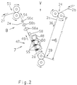
- Figur 2
- eine Variante der Aufbereitungsanordnung gemäß
Figur 1 mit einer V-förmigen Anordnung von Reckstrecke , Auftragstrecke und Raffstrecke.
- Figure 1
- a preparation arrangement according to the invention with a U-shaped arrangement of stretching section, application section and gathering section,
- Figure 2
- a variant of the processing arrangement according to Figure 1 with a V-shaped arrangement of stretching section, application section and gathering section.
Gemäß Figur 1 weist die Aufbereitungsanordnung für einen von einem Ballen 1 abgezogenen Streifen 2 aus Filtertow, z. B. Zelluloseazetat , mit zusammenhängenden Fasern folgende Hauptbaugruppen auf:
Eine Abzugstrecke 3 für einen Abschnitt 2a des Streifens 2, eine Vorreckstrecke 4 für einen Abschnitt 2b des Streifens 2, eine Reckstrecke 6 für einen Abschnitt 2c des Streifens 2, eine Auftragstrecke 7 für einen Abschnitt 2d des Streifens 2, eine Raffstrecke 8 für einen Abschnitt 2e des Streifens 2, eine Zufuhrstrecke 9 zum Zuführen eines Abschnitts 2f zu der Einlaufeinrichtung 11 einer schematisch dargestellten Filterstrangmaschine 12, z. B. vom in der tabakverarbeitenden Industrie bekannten Typ KDF 2 oder KDF 3 der Anmelderin.According to FIG. 1, the processing arrangement for a strip 2 of filter tow, eg. B. cellulose acetate, with coherent fibers the following main assemblies:
A draw-off
Die Abzugstrecke 3, in der der Filtermaterialstreifen 2a entlang des Pfeiles 5 gefördert wird, weist eine oder mehrere Ausbreiterdüsen 16 auf, die Druckluft von einer Druckluftquelle 17 erhalten. Die Druckluft dient zur Ausbreitung des in Richtung des Pfeiles 5 geförderten Filtertowgewebes im Abschnitt 2a. Eine - steuerbare - Ausbreiterdüse ist in der US-A-4 259 769 beschrieben.The draw-off
Über Umlenkrollen 18, 19 gelangt der Filtertowstreifen in die Vorreckstrecke 4, die einerseits von einem Walzenpaar 21 mit den Walzen 22, 23, andererseits von einem Walzenpaar 24 mit motorisch angetriebenen Walzen 26, 27 begrenzt ist - Die Walzen 22, 23 werden vom Towstreifen 2b geschleppt, d. h. sie laufen mit mehr oder weniger Widerstand leer. Wenn erforderlich, können sie motorisch angetrieben werden. Sie können auch in an sich bekannter Weise mit steuerbarer Kraft gegeneinandergedrückt werden. In der Vorreckstrecke , in der der Streifenabschnitt 2b in Richtung des Pfeils 28 schräg nach unten gefördert wird, wird das Filtertow vorgereckt. Es passiert dabei eine Konditioniereinrichtung 29, die als steuerbare Trocknungsvorrichtung 31 ausgebildet ist. In der mit Infrarotstrahlern versehenen Trocknungsvorrichtung 31 wird das Filtertow gesteuert auf eine vorgegebene bevorzugt konstante relative Feuchte (Wasser) konditioniert. Eine geeignete Trocknungsvorrichtung 31 wird unter der Bezeichnung WEKO-HEAT-Trockner von der Firma HAUG GmbH & Co. KG, Postfach 200333, D-70771 Leinfelden-Echterdingen , vertrieben. Ein an sich bekannter Geschwindigkeitsgeber 32, der die Geschwindigkeit des Filterstreifens 2b direkt oder indirekt, etwa in bekannter Weise über die Drehzahl des motorisch angetriebenen Walzenpaares 24, erfaßt, gibt ein von der Geschwindigkeit des Streifenabschnittes 2b abhängiges Signal an einen Eingang a einer Steueranordnung 33, die mittels eines Signals an einem Ausgang d eine elektrische Energieouelle 34 für die Trocknungsvorrichtung 31 derart steuert, daß die Heizleistung sich bei Geschwindigkeitserhöhung des Streifenabschnitts 2b erhöht, bei Geschwindigkeitsverringerung erniedrigt. Die den Eingängen b und c der Steueranordnung 33 zugeführten Signale werden später erläutert.
Der Trocknungsvorrichtung 31 nachgeordnet ist ein Aufladestab 37 zum Aufbringen elektrostatischer Ladungen auf den Filtertowstreifen. Verwendbar ist der von der vorerwähnten Firma HAUG vertriebene Stab mit der Typenbezeichnung ALS A 030-500 mit dem Ladegerät 38 AG-3 neg/7612 und AG-3 pos/7609. Die auf den Streifenabschnitt 2b aufgebrachten elektrostatischen Ladungen hohen Potentials sorgen für eine gute Trennung der einzelnen noch aneinanderhaftenden Fasern des Filtertowstreifens durch elektrostatische Abstoßungskräfte, was für das darauffolgende Aufbringen von Lösungsmitteltröpfchen auf den Filtertowstreifen vorteilhaft ist. Einzelheiten über das Aufbringen von elektrostatischen Ladungen zeigen die US-A-3 817 211 und die US-defensive publication 665 476, US-Official Gazette 860/3 vom 18.03.1969.The filter tow strip reaches the
Downstream of the
An das Walzenpaar 24 schließt sich die eigentliche Reckstrecke 6 an, in der der Abschnitt 2c des Filtertowstreifens senkrecht oder mit einer senkrechten Komponente entsprechend Pfeil 36 von oben nach unten gefördert wird. Am Ende der Reckstrecke 6 befindet sich ein weiteres Walzenpaar 39 aus motorisch angetriebenen Walzen 41, 42, deren Umfangsgeschwindigkeiten etwas größer sind als die Umfangsgeschwindigkeiten der Walzen 26, 27, so daß das elastische Filtertow in Abschnitt 2c definiert gereckt wird. Die Walzenpaare 24 und 39 bilden somit die eigentliche Reckeinrichtung. Die Walzen 26 und 41 weisen eine starre gerillte Oberfläche auf, die jeweils eine nachgiebige Oberfläche der Walzen 27 bzw. 42 berühren. Derartige Walzenkonfigurationen sind durch die vorerwähnten Filtertowaufbereitungsgeräte AF 1, AF 2 und AF 3 der Anmelderin bekannt und z. B. in der US-A-3 317 965 und US-A-3 255 506 beschrieben.
Die Länge c der Reckstrecke kann in besonders vorteilhafter Ausgestaltung der Erfindung, der selbständiger erfinderischer Rang zukommt, zwischen 800 mm und 1200 mm, vorzugsweise etwa 1000 mm, betragen. Es hat sich gezeigt, daß überraschenderweise in diesem Längenbereich eine besonders gute Towausbeute erzielbar ist.The
In a particularly advantageous embodiment of the invention, which has independent inventive rank, the length c of the stretching section can be between 800 mm and 1200 mm, preferably about 1000 mm. It has been shown that, surprisingly, a particularly good tow yield can be achieved in this length range.
Dem Walzen paar 39 ist ein weiteres Walzenpaar 43 aus motorisch angetriebenen Walzen 44, 46 nachgeordnet, deren Umfangsgeschwindigkeiten geringer sind als diejenigen der Walzen 41, 42, so daß das Filtertow sich im Abschnitt 2d bei seiner Förderung entsprechend Pfeil 49 leicht entspannt. Das Walzenpaar 43 weist wieder eine Walze 44 mit starrer gerillter Oberfläche auf, die mit der nachgiebigen Oberfläche der Walze 46 in Berührung steht. Die Walzenpaare 39 und 43 begrenzen somit die zumindest annähernd horizontal angeordnete Auftragstrecke 7, in der eine Auftrageinrichtung 47 in Form einer Besprühvorrichtung 48 angeordnet ist. Die Besprühvorrichtung 48 kann ausgebildet sein, wie in der US-A-4 313 974 beschrieben und besprüht den in Richtung des Pfeils 49 transportierten Abschnitt 2d des Filtertowstreifens von beiden Seiten mit feinen Tröpfchen eines Lösungsmittels für das Filtertowmaterial, z. B. Triazetin. Die Breite des Filtertowstreifens in der Reckstrecke 6 und der Auftragstrecke 7 liegt bevorzugt zwischen 120 mm und 150 mm. Dies ist eine so geringe Breite, daß sie erlaubt, Bearbeitungsvorrichtungen für zwei parallel geführte Filtertowstreifen senkrecht zur Zeichenebene hintereinander anzuordnen und so doppelt zu nutzen. Die Streifen können dann in einer Filterstrangmaschine , die zwei Stränge gleichzeitig verarbeitet, zu Filterstäben verarbeitet werden.The pair of
Der Auftragstrecke nachgeordnet ist die Raffstrecke 8, in der der Abschnitt 2e des Filtertowstreifens senkrecht oder mit überwiegend senkrechter Komponente (wie dargestellt) von einem Walzenpaar 51 mit motorisch angetriebenen Walzen 52, 53 von unten nach oben in Richtung des Pfeils 54 gefördert wird. Die Walze 52 hat wieder eine starre gerillte Oberfläche, die berührende Walze 53 eine nachgiebige Oberfläche. Im Bereich des Abschnitts 2e sind Raffeinrichtungen in Form von Drahtschlaufen 56a ... 56c angeordnet, die die Breite des Filtertows im Abschnitt 2e konstant verringern. Hierzu weisen die Drahtschlaufen unterschiedliche, d. h. kleiner werdende Abmessungen auf.
In der Raffstrecke 8 befindet sich eine Feuchtemeßeinrichtung 57 in Form einer Meßvorrichtung 58 für die Feldstärke, die von elektrostatischen Ladungen hervorgerufen wird, die sich auf dem Filtertowstreifen befinden. Diese elektrostatischen Ladungen rühren von der Reckung in der Reckstrecke 6 her. Zusätzliche Ladungen, wie anhand des Aufladestabes 37 beschrieben, sind bei einer Erfassung der Feldstärke als Feuchtemeßwert des Filtermaterials nicht zweckmäßig. Die Feldstärke ist ein Maß für den Gehalt der Fasern des Filtertows an Wasser. Ein entsprechendes Ausgangssignal wird einem Vergleichsglied 59 zugeführt und dort mit einem von einem Sollwertgeber 61 abgegebenen Sollwert verglichen. Das Ausgangssignal des Vergleichsgliedes 59 beaufschlagt den Eingang b der Steueranordnung 33, deren Eingang c ein Signal von einem Temperaturmeßfühler 62 an der Trocknungsvorrichtung 31 erhält. Die den Eingängen b und c zugeführten Signale steuern zusammen mit dem Eingang a zugeführten Signal die Energieversorgung der Trocknungsvorrichtung 31 derart, daß die relative Feuchte des Filtertows konstant gehalten wird. Dieser vorteilhaften Weiterbildung der Erfindung kommt ebenfalls selbständiger erfinderischer Rang zu.Downstream of the application section is the
In the
Dem Umlenkwalzenpaar 51 nachgeordnet ist die Zufuhrstrecke 9, in der der Abschnitt 2f des Filtertowstreifens in Richtung des Pfeils 62 gefördert und mittels einer Entladeeinrichtung 63 von anhaftenden für die weitere Bearbeitung nachteiligen elektrostatischen Ladungen befreit wird. Es handelt sich um eine Ionisiervorrichtung in Form von Ringelektroden 64a, 64b, wie sie von der vorgenannten Firma HAUG unter der Typenbezeichnung EI-RE 014-200 mit dem Netzteil 66 unter der Typenbezeichnung EN-7/7703 vertrieben wird.
In der Zufuhrstrecke 9 befindet sich außerdem eine angetrie-bene Umlenkrolle 67 mit einer gerundeten Nut 68 am mit Filtertowgeschwindigkeit umlaufenden Umfang sowie eine an sich bekannte sogenannte Stopfdüse 69, der Druckluft von einer ansprechenden Druckluftquelle 71 zugeführt wird. Mit 72 sind ein Einlauftrichter und mit 12 die Filterstrangmaschine bezeichnet.
Die Reckstrecke 6, Auftragstrecke 7 und Raffstrecke 8 bilden zumindest annähernd ein U, wobei die Neigung der Raffstrecke in Richtung auf die Reckstrecke noch größer sein kann als dargestellt.Downstream of the pair of deflecting
In the
The stretching
Von dem Ballen 1 wird ein Filtertowstreifen 2 abgezogen und im Abschnitt 2a zunächst ausgebreitet.
In Abschnitt 2b wird der Filterstreifen von den Walzenpaaren 21 und 24 zunächst vorgereckt , wobei seine relative Feuchte (Wasser) von der Trocknungsvorrichtung 31 auf einem konstanten Wert gehalten wird. Von dem Aufladestab 37 werden elektrostatische Ladungen auf das Filtertow aufgebracht, um die Fasern besser voneinander trennen zu können - In Abschnitt 2c werden die Fasern des Filtertowstreifens durch die mit unterschiedlichen Umfangsgeschwindigkeiten umlaufenden Walzen der Walzenpaare 24 und 39 gereckt , wobei das Walzenpaar 39 die größere Umfangsgeschwindigkeit hat. In Abschnitt 2d werden die Fasern des Filtertowstreifens durch die mit unterschiedlichen Umlaufgeschwindigkeiten umlaufenden Walzen der Walzenpaare 39 und 43 entspannt, weil das Walzenpaar 43 eine niedrigere Umfangsgeschwindigkeit hat als das Walzenpaar 39. Die Besprühvorrichtung 48 besprüht das Filtertow von beiden Seiten mit feinverteilten Tröpfchen eines Lösungsmittels, z. B. Triazetin.
In Abschnitt 2e wird der Filtertowstreifen, der von den Walzenpaaren 51 und 43 gefördert wird, von den Drahtschleifen 56a ... 56c, deren Weite jeweils abnimmt, gerafft, d. h. die Breite senkrecht zur Zeichenebene wird verringert. Gleichzeitig wird die Feuchte von der Meßvorrichtung 58 erfaßt und ein entsprechendes Meßsignal an die Steueranordnung 33 für die Trocknungsvorrichtung 31 gegeben.
In Abschnitt 2f wird das Filtermaterial durch die Ionisiervorrichtung 64a , 64b von seinen elektrostatischen Ladungen befreit und nach Umlenkung an der Rolle 68 über die Stopfdüse 69 dem Trichter 72 und dem Einlauf 11 der Filterstrangmaschine 12 zugeführt.A filter tow strip 2 is pulled off the
In
In
In
Bei der Variante gemäß Figur 2 bildet die Reckstrecke 6 einen Schenkel eines V, während die Auftragstrecke 7 und die Raffstrecke 8 den anderen Schenkel bilden. Die Reckstrecke 6 wird wie bei Figur 1 von den beiden motorisch angetriebenen Walzenpaaren 24 und 39 gebildet. Ihre Länge c liegt ebenfalls bevorzugt zwischen 800 mm und 1200 mm, vorteilhaft bei 1000 mm.
Die Auftrageinrichtung 47 weist eine Besprühvorrichtung 48 auf, die schnelldrehende Rotoren 50 enthält, die die zugeführte Lösungsflüssigkeit in Form von dünnen Sprühfäden 55 auf das Filtertow 2d sprühen. Derartige Auftrageinrichtungen werden von der Firma Weitmann & Konrad GmbH & Co. KG, Postfach 200252, D-70771 Leinfelden-Echterdingen, unter der Bezeichnung WEKO-ROTORENBEFEUCHTUNG FÜR MATERIALBAHNEN vertrieben. Aus Platzgründen ist nur eine Besprühung von einer Seite her dargestellt. Eine Besprühung von beiden Seiten ist mit den vorgenannten Besprüheinrichtungen jedoch ebenfalls möglich.
An die Auftragstrecke 7 schließt sich unmittelbar die Raffstrecke 8 mit ihren Drahtschlaufen 56a ... 56c an, die an dem Walzenpaar 51 endet.
Die der Reckstrecke 6 vorgeordneten sowie die der Auftragstrecke 7 und der Raffstrecke 8 nachgeordneten Anlagenteile können ausgebildet sein wie bei Figur 1 beschrieben.In the variant according to FIG. 2, the stretching
The
The
The plant sections upstream of the stretching
Claims (23)
Applications Claiming Priority (2)
| Application Number | Priority Date | Filing Date | Title |
|---|---|---|---|
| DE4340029 | 1993-11-24 | ||
| DE4340029A DE4340029A1 (en) | 1993-11-24 | 1993-11-24 | Arrangement for preparing a strip of filter material |
Publications (3)
| Publication Number | Publication Date |
|---|---|
| EP0654224A2 true EP0654224A2 (en) | 1995-05-24 |
| EP0654224A3 EP0654224A3 (en) | 1999-10-27 |
| EP0654224B1 EP0654224B1 (en) | 2001-05-02 |
Family
ID=6503321
Family Applications (1)
| Application Number | Title | Priority Date | Filing Date |
|---|---|---|---|
| EP94117723A Expired - Lifetime EP0654224B1 (en) | 1993-11-24 | 1994-11-10 | Device for treating a strip of filter material |
Country Status (8)
| Country | Link |
|---|---|
| US (1) | US5590449A (en) |
| EP (1) | EP0654224B1 (en) |
| JP (1) | JP3534461B2 (en) |
| CN (1) | CN1064222C (en) |
| AT (1) | ATE200851T1 (en) |
| CA (1) | CA2134724C (en) |
| DE (3) | DE4345569B4 (en) |
| ES (1) | ES2157947T3 (en) |
Cited By (6)
| Publication number | Priority date | Publication date | Assignee | Title |
|---|---|---|---|---|
| EP1559333A2 (en) * | 2004-01-29 | 2005-08-03 | Hauni Maschinenbau AG | Separate relaxation and spraying of a filter tow strip |
| EP1834531A1 (en) | 2006-03-10 | 2007-09-19 | Hauni Maschinenbau AG | Treatment of a filter material rod of the tobacco processing industry |
| DE102006011588A1 (en) * | 2006-03-10 | 2007-09-20 | Hauni Maschinenbau Ag | Preparation of a filter material strip of the tobacco processing industry |
| EP2022351A3 (en) * | 2007-08-07 | 2010-09-01 | G.D S.p.A. | An apparatus for processing at least one strip of filters material in the tobacco industry |
| DE102009022759A1 (en) * | 2009-05-26 | 2010-12-02 | Hauni Maschinenbau Ag | Preparation of a filter material strip of the tobacco processing industry |
| WO2011042174A3 (en) * | 2009-10-09 | 2011-06-30 | Philip Morris Products S.A. | A method and apparatus for manufacture of smoking article filter assembly including electrostatically charged fibers |
Families Citing this family (24)
| Publication number | Priority date | Publication date | Assignee | Title |
|---|---|---|---|---|
| US5902431A (en) * | 1997-06-04 | 1999-05-11 | R. J. Reynolds Tobacco Company | Composite web forming apparatus and method |
| DE19756138B4 (en) * | 1997-12-17 | 2005-12-29 | Hauni Maschinenbau Ag | Conveyor arrangement for conveying rod-shaped articles of the tobacco processing industry |
| DE19811014A1 (en) * | 1998-03-13 | 1999-09-16 | Hauni Maschinenbau Ag | Method and device for producing filter rods for rod-shaped articles in the tobacco processing industry |
| DE19951062C2 (en) * | 1999-10-22 | 2002-04-04 | Rhodia Acetow Gmbh | A high performance cigarette filter |
| DE10031848B4 (en) * | 2000-07-04 | 2008-10-30 | Hauni Maschinenbau Ag | Method and device for producing filter rods of the tobacco processing industry |
| WO2002017738A1 (en) | 2000-08-31 | 2002-03-07 | Japan Tobacco Inc. | Filter manufacturing machine |
| DE10157760A1 (en) * | 2001-11-27 | 2003-06-05 | Hauni Maschinenbau Ag | Device for the production of rod-shaped objects |
| DE10200325A1 (en) * | 2002-01-07 | 2003-07-17 | Hauni Maschinenbau Ag | Wear indicator device for a roller |
| DE10200326A1 (en) | 2002-01-07 | 2003-07-17 | Hauni Maschinenbau Ag | Device and method for preparing at least one strip of filter material for the tobacco processing industry |
| US6936446B2 (en) * | 2002-06-19 | 2005-08-30 | Eliminite, Inc. | Light weight medium for growing microorganisms |
| US20040200491A1 (en) * | 2003-04-09 | 2004-10-14 | Karles Georgios D. | On line formation of recessed cigarette filter |
| DE10354924B4 (en) | 2003-11-25 | 2024-01-18 | Körber Technologies Gmbh | Device for processing filter tow material and device for producing filters |
| EP1726225B1 (en) | 2004-03-16 | 2017-01-04 | Japan Tobacco, Inc. | Filter rod manufacturing machine |
| DE102005052660B3 (en) * | 2005-11-04 | 2007-04-26 | Karl Mayer Malimo Textilmaschinenfabrik Gmbh | Device for spreading a carbon fiber tow to form a carbon fiber tape comprises comprises an electric resistance heater and a spreader |
| DE102006011599B4 (en) * | 2006-03-10 | 2007-12-20 | Hauni Maschinenbau Ag | Preparation of a filter material strip of the tobacco processing industry |
| DE102006018101A1 (en) * | 2006-04-18 | 2007-10-25 | Hauni Maschinenbau Ag | Processing unit for processing at least one filter tow strip and a device with at least two such processing units |
| DE102008003368A1 (en) * | 2008-01-08 | 2009-07-09 | Hauni Maschinenbau Aktiengesellschaft | Device for transporting a filter tow |
| DE102008024373A1 (en) | 2008-05-20 | 2009-11-26 | Hauni Maschinenbau Ag | Checking the rotational behavior of a roller |
| DE102009016500B4 (en) * | 2009-04-08 | 2024-02-08 | Körber Technologies Gmbh | Method for operating a filter rod machine and filter rod machine |
| DE102009040092A1 (en) * | 2009-09-04 | 2011-03-10 | Hauni Maschinenbau Ag | Filter rod i.e. cigarette filter rod, producing method for tobacco processing industry, involves directly conveying filter tow strip via high pressure transportation nozzle before insertion of objects |
| DE202015100671U1 (en) * | 2015-02-11 | 2016-05-16 | Daicel Corporation | Cigarette filter manufacturing device and control unit and processor unit for a cigarette filter manufacturing device |
| EP3123877A1 (en) | 2015-07-29 | 2017-02-01 | PT. Gudang Garam Tbk. | Method and apparatus for treating at least one strip of filter material for the production of paper-free filter rods for rod-shaped smoking articles in the tobacco industry |
| CN109222198B (en) * | 2018-08-08 | 2021-05-18 | 河南中烟工业有限责任公司 | Filament bundle perfuming device and method for perfuming cigarette filter stick |
| CN111150095B (en) * | 2020-01-22 | 2021-06-11 | 深圳市联君科技股份有限公司 | Filter stick suction resistance stabilizing device and method |
Citations (7)
| Publication number | Priority date | Publication date | Assignee | Title |
|---|---|---|---|---|
| FR1109940A (en) * | 1953-10-07 | 1956-02-03 | Liggett & Myers Tobacco Compan | Improvements to aerosol filters, particularly for cigarettes, as well as to the process and machine for making them |
| US3013891A (en) * | 1957-09-18 | 1961-12-19 | Lorillard Co P | Tobacco smoke filter material |
| US3317965A (en) * | 1964-09-11 | 1967-05-09 | Osaka Kiko Kabushiki Kaisha | Tow filament separating apparatus |
| US3471901A (en) * | 1966-09-12 | 1969-10-14 | Celanese Corp | Tow processing |
| US3566451A (en) * | 1966-03-02 | 1971-03-02 | Rhodiaceta Ag | Process for widening and loosening continuous artificial fiber |
| US3960645A (en) * | 1974-01-28 | 1976-06-01 | Rothmans Of Pall Mall Canada Limited | Method and apparatus for the opening of tow |
| GB2265296A (en) * | 1992-03-25 | 1993-09-29 | Koerber Ag | Method of and machine for making filters for tobacco smoke |
Family Cites Families (7)
| Publication number | Priority date | Publication date | Assignee | Title |
|---|---|---|---|---|
| US3255506A (en) * | 1963-02-20 | 1966-06-14 | Eastman Kodak Co | Tow treatment |
| US3817211A (en) * | 1972-02-22 | 1974-06-18 | Owens Corning Fiberglass Corp | Apparatus for impregnating strands, webs, fabrics and the like |
| DE2814681A1 (en) * | 1978-04-05 | 1979-10-18 | Hauni Werke Koerber & Co Kg | METHOD AND DEVICE FOR APPLYING PLASTICIZER TO A MOVING FABRIC |
| DE2814605A1 (en) * | 1978-04-05 | 1979-10-18 | Hauni Werke Koerber & Co Kg | METHOD AND DEVICE FOR SPREADING A MOVING AIR-PERMEABLE WEB OF FABRIC |
| DE3401373A1 (en) * | 1983-02-01 | 1984-08-02 | Hauni-Werke Körber & Co KG, 2050 Hamburg | Method and apparatus for producing filter rods in the tobacco processing industry |
| IT1272020B (en) * | 1992-03-26 | 1997-06-10 | Koerber Ag | PROCEDURE AND MACHINE FOR TREATING MATERIAL FOR A FILTER CORD. |
| JPH0799958A (en) * | 1993-10-07 | 1995-04-18 | Daicel Chem Ind Ltd | Dispersible cigarette filter |
-
1993
- 1993-11-24 DE DE4345569A patent/DE4345569B4/en not_active Expired - Fee Related
- 1993-11-24 DE DE4340029A patent/DE4340029A1/en not_active Ceased
-
1994
- 1994-10-31 CA CA002134724A patent/CA2134724C/en not_active Expired - Fee Related
- 1994-11-03 US US08/334,181 patent/US5590449A/en not_active Expired - Lifetime
- 1994-11-10 DE DE59409739T patent/DE59409739D1/en not_active Expired - Lifetime
- 1994-11-10 EP EP94117723A patent/EP0654224B1/en not_active Expired - Lifetime
- 1994-11-10 AT AT94117723T patent/ATE200851T1/en not_active IP Right Cessation
- 1994-11-10 ES ES94117723T patent/ES2157947T3/en not_active Expired - Lifetime
- 1994-11-22 JP JP28817694A patent/JP3534461B2/en not_active Expired - Fee Related
- 1994-11-23 CN CN94118997A patent/CN1064222C/en not_active Expired - Fee Related
Patent Citations (7)
| Publication number | Priority date | Publication date | Assignee | Title |
|---|---|---|---|---|
| FR1109940A (en) * | 1953-10-07 | 1956-02-03 | Liggett & Myers Tobacco Compan | Improvements to aerosol filters, particularly for cigarettes, as well as to the process and machine for making them |
| US3013891A (en) * | 1957-09-18 | 1961-12-19 | Lorillard Co P | Tobacco smoke filter material |
| US3317965A (en) * | 1964-09-11 | 1967-05-09 | Osaka Kiko Kabushiki Kaisha | Tow filament separating apparatus |
| US3566451A (en) * | 1966-03-02 | 1971-03-02 | Rhodiaceta Ag | Process for widening and loosening continuous artificial fiber |
| US3471901A (en) * | 1966-09-12 | 1969-10-14 | Celanese Corp | Tow processing |
| US3960645A (en) * | 1974-01-28 | 1976-06-01 | Rothmans Of Pall Mall Canada Limited | Method and apparatus for the opening of tow |
| GB2265296A (en) * | 1992-03-25 | 1993-09-29 | Koerber Ag | Method of and machine for making filters for tobacco smoke |
Cited By (14)
| Publication number | Priority date | Publication date | Assignee | Title |
|---|---|---|---|---|
| EP1559333A2 (en) * | 2004-01-29 | 2005-08-03 | Hauni Maschinenbau AG | Separate relaxation and spraying of a filter tow strip |
| JP2005211071A (en) * | 2004-01-29 | 2005-08-11 | Hauni Maschinenbau Ag | Separate relaxation and spraying of filter tow strip |
| EP1559333A3 (en) * | 2004-01-29 | 2007-03-21 | Hauni Maschinenbau AG | Separate relaxation and spraying of a filter tow strip |
| EP1834531A1 (en) | 2006-03-10 | 2007-09-19 | Hauni Maschinenbau AG | Treatment of a filter material rod of the tobacco processing industry |
| DE102006011588A1 (en) * | 2006-03-10 | 2007-09-20 | Hauni Maschinenbau Ag | Preparation of a filter material strip of the tobacco processing industry |
| DE102006011587A1 (en) * | 2006-03-10 | 2007-09-27 | Hauni Maschinenbau Ag | Preparation of a filter material strip of the tobacco processing industry |
| DE102006011587B4 (en) * | 2006-03-10 | 2008-04-03 | Hauni Maschinenbau Ag | Preparation of a filter material strip of the tobacco processing industry |
| DE102006011588B4 (en) * | 2006-03-10 | 2008-04-10 | Hauni Maschinenbau Ag | Preparation of a filter material strip of the tobacco processing industry |
| EP2022351A3 (en) * | 2007-08-07 | 2010-09-01 | G.D S.p.A. | An apparatus for processing at least one strip of filters material in the tobacco industry |
| DE102009022759A1 (en) * | 2009-05-26 | 2010-12-02 | Hauni Maschinenbau Ag | Preparation of a filter material strip of the tobacco processing industry |
| WO2011042174A3 (en) * | 2009-10-09 | 2011-06-30 | Philip Morris Products S.A. | A method and apparatus for manufacture of smoking article filter assembly including electrostatically charged fibers |
| US8534294B2 (en) | 2009-10-09 | 2013-09-17 | Philip Morris Usa Inc. | Method for manufacture of smoking article filter assembly including electrostatically charged fiber |
| US9788572B2 (en) | 2009-10-09 | 2017-10-17 | Philip Morris Usa Inc. | Method and apparatus for manufacture of smoking article filter assembly including electrostatically charged fibers |
| US10226070B2 (en) | 2009-10-09 | 2019-03-12 | Philip Morris Usa Inc. | Filter rod including electrostatically charged fibers |
Also Published As
| Publication number | Publication date |
|---|---|
| JPH07203935A (en) | 1995-08-08 |
| DE4340029A1 (en) | 1995-06-01 |
| ES2157947T3 (en) | 2001-09-01 |
| ATE200851T1 (en) | 2001-05-15 |
| JP3534461B2 (en) | 2004-06-07 |
| US5590449A (en) | 1997-01-07 |
| DE59409739D1 (en) | 2001-06-07 |
| EP0654224B1 (en) | 2001-05-02 |
| CN1064222C (en) | 2001-04-11 |
| CA2134724A1 (en) | 1995-05-25 |
| DE4345569B4 (en) | 2006-06-08 |
| CN1108072A (en) | 1995-09-13 |
| EP0654224A3 (en) | 1999-10-27 |
| CA2134724C (en) | 2007-04-17 |
Similar Documents
| Publication | Publication Date | Title |
|---|---|---|
| EP0654224B1 (en) | Device for treating a strip of filter material | |
| EP0919144B2 (en) | Method and device for treating a stream of filter tow | |
| EP1847186B1 (en) | Processing unit for processing at least one strip of filter tow for manufacturing filters for rod-shaped tobacco articles | |
| DD203682A5 (en) | METHOD AND DEVICE FOR PRODUCING CIGARETTE FILTER STAINS | |
| CH628375A5 (en) | Spin method for spinning of individual fibres to a thread. | |
| EP0941673B1 (en) | Method and apparatus for the manufacturing of rod filter for rod-shaped article in the tobacco industry | |
| DE1141928B (en) | Process for producing a rod suitable for tobacco smoke filters and apparatus for carrying out the process | |
| EP1847187B1 (en) | Processing unit for processing at least one filter strip and device with at least two such processing units | |
| DE1657244B1 (en) | Method and device for the production of fiber rods, in particular for use as a cigarette filter | |
| DE1188998C2 (en) | Method and device for producing a filter material strand for tobacco smoke filters or the like. | |
| AT392490B (en) | SPINNING PROCESS AND SPINNING DEVICE | |
| EP1913823B1 (en) | Apparatus and method for processing filter material for cigarette filters or the like | |
| DE3337007T1 (en) | Method and device for the improved pneumatic loosening of fiber tows | |
| DE4209606A1 (en) | Method and device for treating at least one web of threads filter material for cigarette filters | |
| EP0715816A2 (en) | Method and device for forming a filter rod in the tobacco industry | |
| DE2815025A1 (en) | METHOD AND ARRANGEMENT FOR FORMING A FILTER STRAND | |
| DE6608412U (en) | DEVICE FOR CONTINUOUS FEEDING OF CUT TOBACCO TO A STRAND CIGARETTE MACHINE. | |
| DE3431428A1 (en) | LARGE BALE PRESS FOR AGRICULTURAL HARVEST | |
| EP1834531B1 (en) | Treatment of a filter material rod of the tobacco processing industry | |
| DE102005007214A1 (en) | Preparation of a strip of filter material from the tobacco processing industry | |
| WO2001014623A2 (en) | Method and device for influencing the structure and position of fibres during the aerodynamic formation of non-wovens | |
| DE1632184B1 (en) | Guide and adjustment device for a pair of rollers in a plant for the production of cigarette filter rods | |
| EP1834529B1 (en) | Treatment of a filter material rod of the tobacco processing industry | |
| DE1432623B1 (en) | Method and device for producing filter rods for cigarettes or the like. | |
| DE2521391C2 (en) | Stretching device for a filter manufacturing machine in the tobacco processing industry |
Legal Events
| Date | Code | Title | Description |
|---|---|---|---|
| PUAI | Public reference made under article 153(3) epc to a published international application that has entered the european phase |
Free format text: ORIGINAL CODE: 0009012 |
|
| AK | Designated contracting states |
Kind code of ref document: A2 Designated state(s): AT BE CH DE ES FR GB IT LI NL SE |
|
| RAP1 | Party data changed (applicant data changed or rights of an application transferred) |
Owner name: HAUNI MASCHINENBAU AKTIENGESELLSCHAFT |
|
| PUAL | Search report despatched |
Free format text: ORIGINAL CODE: 0009013 |
|
| AK | Designated contracting states |
Kind code of ref document: A3 Designated state(s): AT BE CH DE ES FR GB IT LI NL SE |
|
| 17P | Request for examination filed |
Effective date: 20000412 |
|
| GRAG | Despatch of communication of intention to grant |
Free format text: ORIGINAL CODE: EPIDOS AGRA |
|
| 17Q | First examination report despatched |
Effective date: 20000801 |
|
| GRAG | Despatch of communication of intention to grant |
Free format text: ORIGINAL CODE: EPIDOS AGRA |
|
| GRAH | Despatch of communication of intention to grant a patent |
Free format text: ORIGINAL CODE: EPIDOS IGRA |
|
| GRAH | Despatch of communication of intention to grant a patent |
Free format text: ORIGINAL CODE: EPIDOS IGRA |
|
| GRAA | (expected) grant |
Free format text: ORIGINAL CODE: 0009210 |
|
| ITF | It: translation for a ep patent filed |
Owner name: DE DOMINICIS & MAYER S.R.L. |
|
| AK | Designated contracting states |
Kind code of ref document: B1 Designated state(s): AT BE CH DE ES FR GB IT LI NL SE |
|
| REF | Corresponds to: |
Ref document number: 200851 Country of ref document: AT Date of ref document: 20010515 Kind code of ref document: T |
|
| REG | Reference to a national code |
Ref country code: CH Ref legal event code: EP |
|
| GBT | Gb: translation of ep patent filed (gb section 77(6)(a)/1977) |
Effective date: 20010516 |
|
| REF | Corresponds to: |
Ref document number: 59409739 Country of ref document: DE Date of ref document: 20010607 |
|
| PG25 | Lapsed in a contracting state [announced via postgrant information from national office to epo] |
Ref country code: SE Free format text: LAPSE BECAUSE OF FAILURE TO SUBMIT A TRANSLATION OF THE DESCRIPTION OR TO PAY THE FEE WITHIN THE PRESCRIBED TIME-LIMIT Effective date: 20010802 |
|
| REG | Reference to a national code |
Ref country code: ES Ref legal event code: FG2A Ref document number: 2157947 Country of ref document: ES Kind code of ref document: T3 |
|
| ET | Fr: translation filed | ||
| PG25 | Lapsed in a contracting state [announced via postgrant information from national office to epo] |
Ref country code: AT Free format text: LAPSE BECAUSE OF NON-PAYMENT OF DUE FEES Effective date: 20011110 |
|
| PG25 | Lapsed in a contracting state [announced via postgrant information from national office to epo] |
Ref country code: BE Free format text: LAPSE BECAUSE OF NON-PAYMENT OF DUE FEES Effective date: 20011130 |
|
| REG | Reference to a national code |
Ref country code: GB Ref legal event code: IF02 |
|
| PLBE | No opposition filed within time limit |
Free format text: ORIGINAL CODE: 0009261 |
|
| STAA | Information on the status of an ep patent application or granted ep patent |
Free format text: STATUS: NO OPPOSITION FILED WITHIN TIME LIMIT |
|
| 26N | No opposition filed | ||
| BERE | Be: lapsed |
Owner name: HAUNI MASCHINENBAU A.G. Effective date: 20011130 |
|
| PGFP | Annual fee paid to national office [announced via postgrant information from national office to epo] |
Ref country code: CH Payment date: 20081124 Year of fee payment: 15 |
|
| PGFP | Annual fee paid to national office [announced via postgrant information from national office to epo] |
Ref country code: ES Payment date: 20081113 Year of fee payment: 15 |
|
| PGFP | Annual fee paid to national office [announced via postgrant information from national office to epo] |
Ref country code: FR Payment date: 20081117 Year of fee payment: 15 |
|
| PGFP | Annual fee paid to national office [announced via postgrant information from national office to epo] |
Ref country code: GB Payment date: 20081119 Year of fee payment: 15 |
|
| REG | Reference to a national code |
Ref country code: CH Ref legal event code: PL |
|
| GBPC | Gb: european patent ceased through non-payment of renewal fee |
Effective date: 20091110 |
|
| REG | Reference to a national code |
Ref country code: FR Ref legal event code: ST Effective date: 20100730 |
|
| PG25 | Lapsed in a contracting state [announced via postgrant information from national office to epo] |
Ref country code: LI Free format text: LAPSE BECAUSE OF NON-PAYMENT OF DUE FEES Effective date: 20091130 Ref country code: FR Free format text: LAPSE BECAUSE OF NON-PAYMENT OF DUE FEES Effective date: 20091130 Ref country code: CH Free format text: LAPSE BECAUSE OF NON-PAYMENT OF DUE FEES Effective date: 20091130 |
|
| PG25 | Lapsed in a contracting state [announced via postgrant information from national office to epo] |
Ref country code: GB Free format text: LAPSE BECAUSE OF NON-PAYMENT OF DUE FEES Effective date: 20091110 |
|
| REG | Reference to a national code |
Ref country code: ES Ref legal event code: FD2A Effective date: 20110310 |
|
| PG25 | Lapsed in a contracting state [announced via postgrant information from national office to epo] |
Ref country code: ES Free format text: LAPSE BECAUSE OF NON-PAYMENT OF DUE FEES Effective date: 20110309 |
|
| PG25 | Lapsed in a contracting state [announced via postgrant information from national office to epo] |
Ref country code: ES Free format text: LAPSE BECAUSE OF NON-PAYMENT OF DUE FEES Effective date: 20091111 |
|
| PGFP | Annual fee paid to national office [announced via postgrant information from national office to epo] |
Ref country code: IT Payment date: 20121121 Year of fee payment: 19 |
|
| PGFP | Annual fee paid to national office [announced via postgrant information from national office to epo] |
Ref country code: NL Payment date: 20121121 Year of fee payment: 19 |
|
| PGFP | Annual fee paid to national office [announced via postgrant information from national office to epo] |
Ref country code: DE Payment date: 20121227 Year of fee payment: 19 |
|
| REG | Reference to a national code |
Ref country code: NL Ref legal event code: V1 Effective date: 20140601 |
|
| PG25 | Lapsed in a contracting state [announced via postgrant information from national office to epo] |
Ref country code: IT Free format text: LAPSE BECAUSE OF NON-PAYMENT OF DUE FEES Effective date: 20131110 Ref country code: DE Free format text: LAPSE BECAUSE OF NON-PAYMENT OF DUE FEES Effective date: 20140603 Ref country code: NL Free format text: LAPSE BECAUSE OF NON-PAYMENT OF DUE FEES Effective date: 20140601 |
|
| REG | Reference to a national code |
Ref country code: DE Ref legal event code: R119 Ref document number: 59409739 Country of ref document: DE Effective date: 20140603 |