EP0653879A2 - Method of and system for predicting a colour reproduction image - Google Patents
Method of and system for predicting a colour reproduction image Download PDFInfo
- Publication number
- EP0653879A2 EP0653879A2 EP94118139A EP94118139A EP0653879A2 EP 0653879 A2 EP0653879 A2 EP 0653879A2 EP 94118139 A EP94118139 A EP 94118139A EP 94118139 A EP94118139 A EP 94118139A EP 0653879 A2 EP0653879 A2 EP 0653879A2
- Authority
- EP
- European Patent Office
- Prior art keywords
- color
- data
- image
- color space
- color image
- Prior art date
- Legal status (The legal status is an assumption and is not a legal conclusion. Google has not performed a legal analysis and makes no representation as to the accuracy of the status listed.)
- Granted
Links
- 238000000034 method Methods 0.000 title claims description 39
- 238000006243 chemical reaction Methods 0.000 claims abstract description 110
- 239000000463 material Substances 0.000 claims description 65
- 238000007639 printing Methods 0.000 claims description 60
- 238000013507 mapping Methods 0.000 abstract description 32
- 239000000976 ink Substances 0.000 description 31
- 238000012545 processing Methods 0.000 description 15
- 239000003086 colorant Substances 0.000 description 6
- 238000010586 diagram Methods 0.000 description 6
- 230000000694 effects Effects 0.000 description 5
- 238000012937 correction Methods 0.000 description 4
- 239000011159 matrix material Substances 0.000 description 4
- 238000000926 separation method Methods 0.000 description 4
- 238000010521 absorption reaction Methods 0.000 description 2
- 230000007423 decrease Effects 0.000 description 2
- 239000006185 dispersion Substances 0.000 description 2
- 230000006978 adaptation Effects 0.000 description 1
- 238000003491 array Methods 0.000 description 1
- 230000015572 biosynthetic process Effects 0.000 description 1
- 235000019646 color tone Nutrition 0.000 description 1
- 238000011161 development Methods 0.000 description 1
- 230000007613 environmental effect Effects 0.000 description 1
- 238000003384 imaging method Methods 0.000 description 1
- 238000005259 measurement Methods 0.000 description 1
- 238000012986 modification Methods 0.000 description 1
- 230000004048 modification Effects 0.000 description 1
- 238000007645 offset printing Methods 0.000 description 1
- 230000003287 optical effect Effects 0.000 description 1
- 239000003973 paint Substances 0.000 description 1
- 239000000123 paper Substances 0.000 description 1
- 230000035945 sensitivity Effects 0.000 description 1
- 230000003595 spectral effect Effects 0.000 description 1
- 230000000007 visual effect Effects 0.000 description 1
- XLYOFNOQVPJJNP-UHFFFAOYSA-N water Substances O XLYOFNOQVPJJNP-UHFFFAOYSA-N 0.000 description 1
Images


Classifications
-
- H—ELECTRICITY
- H04—ELECTRIC COMMUNICATION TECHNIQUE
- H04N—PICTORIAL COMMUNICATION, e.g. TELEVISION
- H04N1/00—Scanning, transmission or reproduction of documents or the like, e.g. facsimile transmission; Details thereof
- H04N1/46—Colour picture communication systems
- H04N1/56—Processing of colour picture signals
- H04N1/60—Colour correction or control
- H04N1/6011—Colour correction or control with simulation on a subsidiary picture reproducer
-
- H—ELECTRICITY
- H04—ELECTRIC COMMUNICATION TECHNIQUE
- H04N—PICTORIAL COMMUNICATION, e.g. TELEVISION
- H04N1/00—Scanning, transmission or reproduction of documents or the like, e.g. facsimile transmission; Details thereof
- H04N1/46—Colour picture communication systems
- H04N1/56—Processing of colour picture signals
- H04N1/60—Colour correction or control
- H04N1/603—Colour correction or control controlled by characteristics of the picture signal generator or the picture reproducer
Definitions
- the present invention relates to a method of and a system for predicting a reproduced color image by establishing a color space data conversion formula with printing conditions such as print paper, ink, etc. used as parameters, converting color image data into color space data for an image monitor device according to the established color space data conversion formula, and outputting the color space data to make it possible to predict colors easily and highly accurately.
- a printed material is produced according to a number of processing steps. More specifically, color separation films of Y, M, C, K are generated on the basis of color image data supplied from an image input device, and presensitized plates are exposed to color images through the color separation films. Then, the color images on the presensitized plates are developed, and the presensitized plates are set on a printing press to produce a printed material.
- the colors on the printed material which are finally produced depend on various printing conditions including the paper, inks, and water used, the type of the printing press, and the screen ruling and dot shape which are employed for the formation of dot-matrix images.
- the disclosed system comprises means for determining tristimulus appearance signals, which are of a common color data format, from a colored original document, means for effecting aesthetic correction on the tristimulus appearance signals, means for displaying a corrected color image based on the corrected tristimulus appearance signals, and means for selecting color materials for a hard copy to obtain reproduction signals which colorimetrically match the displayed color image.
- a combination of color materials selected by the color material selecting means is printed, and the printed color materials are measured by a colorimeter.
- the reproduction signals are then corrected based on the measured data to achieve a match between the printed color image and the displayed color image.
- the above conventional system is, however, not suitable for use in applications where complex conditions are involved, such as in a process of producing a printed material.
- a printed material For producing a printed material, it is necessary to establish not only color materials, but also output conditions including the type of the support layer of a printed material, the number of colors to be printed, a K (black) printer quantity, and a screen ruling, and also printing press conditions including a printing order, a printing pressure, color material quantities, and a printing speed. It is not practical to effect measuring and correcting processes with respect to all these conditions for reproducing a color image highly accurately.
- Color ranges that can be reproduced by printing processes are narrow, and differ from printing conditions to printing conditions. Since the conversion from color image data to YMCK halftone dot percentage data depends on the operator and the equipment used for the conversion, it is highly difficult to make a common color data format, e.g., tristimulus values of an XYZ colorimetric system, correspond uniquely to YMCK halftone dot percentage data for printing.
- a dot gain into account if a continuous-gradation image is to be formed on a support by area modulation.
- the light reflected from an area-modulated image formed on a support varies depending on the material of the support and the characteristics of inks that are used to form the image. It is also known the reflected light varies depending on the screen ruling and dot shape of the area-modulated image.
- the dot gain varies depending on the wavelength of illuminating light which is used to determine and specify the colors of a print. Specifically, prints that are printed with the same color materials exhibit a different dot gain depending on the color representing coordinates that are measured. The dot gain also depends on the ratio of an area which is printed in another color. For example, the dot gain of a cyan ink printed over a magenta ink is usually of a value smaller than the dot gain of a cyan ink printed over a white background.
- a second object of the present invention is to provide a method of and a system for predicting a reproduced color image while taking effects of a dot gain into account.
- a system for predicting a reproduced color image in producing a color printed material from processed input color image data through a platemaking and printing process and outputting a color image corresponding to the color printed material comprising printing condition profiles which represent printing conditions of the color printed material established as parameters, data conversion profiles which represent color space data conversion formulas established for converting the processed input color image data into data in a color space of an image monitor device using the parameters represented by the printing condition profiles, and converting means for converting the processed input color image data into the data in the color space of the image monitor device according to the color space data conversion formulas, the arrangement being such that a color image corresponding to the color printed material can be displayed from the data in the color space.
- color image data are converted into data in a color space of the image monitor device with color space data conversion formulas established with respect to the printing conditions, and then reproduced and outputted.
- a method of predicting a reproduced color image in generating area modulation data of respective color materials from processed input color image data and producing a color printed material based on the area modulation data comprising the steps of correcting the area modulation data based on dot gain correcting coefficients established for respective color representing coordinates of an image with respect to the respective color materials of the color printed material, generating color image data of the color representing coordinates from the corrected area modulation data, and displaying a color image corresponding to the color printed material based on the color image data of the color representing coordinates.
- a system for predicting a reproduced color image in generating area modulation data of respective color materials from processed input color image data, producing a color printed material based on the area modulation data, and displaying a color image corresponding to the color printed material comprising printing condition profiles which represent printing conditions established as parameters, the printing conditions including dot gain correcting coefficients established for respective color representing coordinates of an image with respect to the respective color materials of the color printed material, corrective formula profiles which represent corrective formulas established for correcting the area modulation data based on the dot gain correcting coefficients, and conversion formula profiles which represent conversion formulas established for converting the corrected area modulation data into color image data corresponding to the respective color representing coordinates, the arrangement being such that color image data suitable for an image monitor device can be produced from the color image data corresponding to the respective color representing coordinates.
- area modulation data are corrected using dot gain correcting coefficients established for respective color representing coordinates of an image according to printing conditions, color image data corresponding to the color representing coordinates are converted from the corrected area modulation data, and a monitor image is produced from the converted color image data. In this manner, an image to be printed can be predicted highly accurately.
- a system for predicting a reproduced color image generally comprises an image input unit 10 for reading color image data from a color original document or an external device, an image editor 12 for effecting image processing including an aesthetic process on the color image data thus read, an image output unit (image monitor device) 14A for displaying or outputting the processed color image data on a CRT, a color printer, or the like for predicting colors, an image output unit 14B for outputting the processed color image as a color printed material, an image processor 16 for converting the color image data into color image data that can be handled by the image output unit 14A, and a device profile generator 18 for generating a device profile group of device profiles which represent characteristics of the image output units 14A, 14B, and characteristics of a color reproduction process and color reproduction mediums including color materials, a support layer, phosphors, etc.
- the image input unit 10 has three or more sensors having different spectral sensitivities for reading the image densities of pixels of a color original document.
- the image input unit 10 may comprise a drum-type scanner for reading the image densities of pixels of a color original document mounted on a drum in synchronism with rotation of the drum, or a flatbed scanner for reading the image densities of pixels of a color original document with either a line sensor composed of a single array or a plurality of arrays of photoelectric transducers or a two-dimensional sensor composed of a two-dimensional matrix of photoelectric transducers.
- the image editor 12 effects image processing including an aesthetic process on the color image data from the image input unit 10 to generate YMCK halftone dot percentage data supplied to the image output unit 14B.
- the image output unit 14B produces Y, M, C, K color separation films for generating presensitized plates to produce a printed material, based on the YMCK halftone dot percentage data supplied as color image data from the image editor 12, then generates presensitized plates from the Y, M, C, K color separation films, and produces a printed material from the presensitized plates.
- the image output unit 14A may comprise a CRT, a color printer, or the like for displaying or outputting a color image having the same color representation and image quality as the printed material generated by the image output unit 14B.
- the image processor 16 comprises a common color space LUT generator 20 for generating a conversion table (hereinafter referred to as an "LUT") for converting the YMCK halftone dot percentage data supplied as color image data from the image editor 12 into color image data in a common color space, a gamut mapping (reproducible color range)/appearance LUT generator 22 for generating an LUT for compressing or converting a gamut mapping of the image input unit 10 in the common color space into a gamut mapping in the image output unit 14A, and making appearance adjustments depending on the difference between observing conditions, a device color space (specific color space) LUT generator 24 for generating an LUT for converting the color image data in the common color space into color image data in the device color space of the image output unit 14A, and an LUT combiner/converter 26 for generating a combined LUT composed of all or some of the LUTs generated by the common color space LUT generator 20, the gamut mapping/appearance LUT generator 22, and the device color space LUT generator 24
- the common color space conversion table generated by the common color space LUT generator 20, the gamut mapping/appearance LUT generated by the gamut mapping/appearance LUT generator 22, the device color space LUT generated by the device color space LUT generator 24, and the combined LUT generated by the LUT combiner/converter 26 are stored respectively in data files 28, 30, 32, 34.
- the LUT combiner/converter 26 combines LUTs generated by the LUT generators 20, 22, 24, and converts color image data read by the image input unit 10 into color image data using the combined LUT and outputs the color image data to the image output unit 14A.
- the common color space is a color space composed of data not depending on the input and output units and the output medium, such as a CIE-XYZ colorimetric system, an L*a*b* colorimetric system, an YCC colorimetric system which can uniquely be converted mathematically to and from the CIE-XYZ colorimetric system or the L*a*b* colorimetric system, an YIQ colorimetric system, or an RGB colorimetric system representing the phosphors of a display monitor such as a CRT or the like. It is therefore possible to carry out desired image processing in the common color space without concern over the input and output units and the output medium.
- the device color space is a color space composed of particular data handled by the image input unit 10 and the image output units 14A, 14B.
- the device profile generator 18 has measuring units for measuring various physical characteristics as desired, establishes color space data conversion formulas, relationship formulas and parameters used in the data processing in the image processor 16 as a device profile group, and stores the device profile group in a data file 36.
- the device profile group is a collection of profiles representing, in a common data format, color reproduction processes in the image output devices 14A, 14B, environmental conditions in which they are used, physical factors and characteristics of materials of a color original document and a recording medium, and formulas which couple these data. Basically, as shown in FIG.
- the device profile group includes a printing/common color space conversion profile group for generating a common color space conversion table for converting YMCK halftone dot percentage data supplied from the image editor 12 into color image data in a common color space such as of a CIE-XYZ colorimetric system, an RGB colorimetric system, an L*a*b* colorimetric system, or the like while taking various printing conditions into account, a gamut mapping/appearance conversion profile group for generating a gamut mapping/appearance conversion table for converting the gamut mapping and appearance of the color image data in the common color space into a desired gamut mapping and appearance while taking into account the gamut mapping and appearance in the image output unit 14A, and an output device profile group for converting the color image data in the common color space into color image data in the device color space in the image output unit 14A.
- Each of the above profile groups includes basic profiles, subprofiles, and condition profiles.
- FIG. 3 shows, by way of example, the basic profiles (conversion formula profiles) and subprofiles (corrective formula profiles) of the printing/common color space conversion profile group which is defined in relation to the color reproduction process in the image output device 14B.
- the basic profiles represent (1) a dot modulation process using the Neugebauer's equation, (2) a conversion process using a look-up table, and (3) another process, respectively, which can be selected one at a time.
- One of these basic profiles is selected depending on the color reproduction process in the image output device 14B, and established as a color space data conversion formula for conversion between the common color space and the device color space of the image output device 14B.
- the Neugebauer's equation is a color-predicting basic function which defines the relationship between the XYZ and YMCK colorimetric systems in the CIE common color space, and is defined according to the equation (1) below.
- X, Y, Z represent tristimulus values in the XYZ colorimetric system
- X c , X m , X y , X k , etc. represent XYZ stimulus values (single-color stimulus values) with respect to single-color inks of Y, M, C, and K
- X w , etc. represent tristimulus values of the support layer of the printed material, X cm , X cmy , X cmyk , etc.
- X cm represents XYZ stimulus values of an area where inks of C and M are superimposed
- c x , m x , y x , k x , etc. represent dot % values of inks of C, M, Y, K at the time they are observed with color light corresponding to color matching functions x( ⁇ ), and c Xm , c Xmy , C Xmyk , etc.
- C Xmy represents a dot % value for making a correction with respect to the presence of the inks of M and Y (higher-order color dot gain correction).
- C Xmy represents a dot % value for making a correction with respect to the presence of the inks of M and Y (higher-order color dot gain correction). Since the XYZ colorimetric system has a one-to-one correspondence to the L*a*b* colorimetric system or the RGB colorimetric system, the Neugebauer's equation can also be defined as an equation indicative of the relationship between the L*a*b* colorimetric system and the YMCK colorimetric system.
- a subprofile in which set values can be selected according to predetermined relationship equations or output conditions. For example, if (1) the dot modulation process using the Neugebauer's equation is selected as the basic profile, then its variables are classified into (11) a dot gain conversion formula (c X , m X , c Xm , c Xmy , etc.), (12) single-color stimulus values (X c , X m , X y , X k , etc.), and (13) higher-order color stimulus values (X cm , X cmy , X cmyk , etc.), and subprofiles are established for each of these sets of values.
- a dot gain conversion formula c X , m , c Xm , c Xmy , etc.
- X c , X m , X y , X k , etc. (12) single-color stimulus values (X c , X m ,
- the dot gain conversion formula it is possible to select a desired subprofile from (21) a single conversion formula, (22) an XYZ independent conversion formula, and (23) another formula.
- For the single-color stimulus values it is possible to select a desired subprofile from (31) a single-color stimulus value table, (32) a theoretical formula, and (33) another formula.
- For the higher-order color stimulus values it is possible to select a desired subprofile from (41) a higher-order color stimulus value table, (42) a theoretical formula, and (43) another formula.
- the single conversion formula represents a process for representing and processing c X , c Y , c Z , etc.
- the XYZ independent conversion formula represents a process for establishing and processing c X , c Y , c Z , etc. independently for each of X, Y, Z.
- a desired subprofile can be selected from (51) a perimeter conversion formula, (52) a quadratic equation conversion formula, and (53) another formula.
- a desired subprofile can be selected from (61) a first-order color dot gain conversion formula, (62) a higher-order color dot gain conversion formula, and (63) another formula.
- the perimeter conversion formula is defined by: where ⁇ p , ⁇ m are gain coefficients, and L the screen ruling.
- the gain coefficient ⁇ p is a parameter depending on the paper on which the color image is to be printed, and the gain coefficient ⁇ m is a parameter depending on the printing press and the ink.
- the applicant has found out that the dot gain of the printed material differs depending on the wavelength of the illuminating light used when it is measured, and hence differs with respect to each of the tristimulus values X, Y, Z.
- FIG. 4 shows printing output condition profiles of the printing/common color space conversion profile group shown in FIG. 2.
- the printing output condition profiles represent output conditions used for generating a printed material.
- the printing output condition profiles are composed of a support layer profile for defining parameters ( ⁇ p , ⁇ pX , ⁇ pY , ⁇ pZ , g3, a cXy , b cXy , etc.) relative to the paper of the support layer of the printed material, a screen ruling/dot shape profile for defining parameters (L, g4, etc.) relatively to the screen ruling and the dot shape, an ink profile for defining parameters (g2, ⁇ m , a single-color stimulus value table, a higher-order color stimulus value table, theoretical formula parameters, etc.) relatively to the characteristics of inks used in the printing, a black printer quantity profile for defining parameters (p, k , etc.) relative to a black printer quantity (described later on), a look-up table to
- the gamut mapping/appearance conversion profile group is composed of basic profiles representing (71) an LMN conversion process based on a combination of nonlinear conversion and 3 x 3 matrix conversion and (72) another process, one of which can be selected at a time, and subprofiles representing (81) an LMN conversion matrix, (82) a nonlinear conversion table, and (83) another table, one of which can be selected at a time with respect to the LMN conversion process.
- Variables relative to (91) an input range, (92) an output range, (93) a white point, and (94) a black point are established with respect to the nonlinear conversion table, using the parameters of the condition profiles of the printing/common color space conversion profile group, the gamut mapping/appearance conversion profile group, and the output device profile group (see “Reference Manual for Postscript", 2nd edition, published by ASCII Publishing Department).
- the image output unit 14A is a color printer, then observing conditions of the gamut mapping/appearance conversion profile group are arranged as shown in FIG. 6.
- the observing conditions include parameters relative to an observing light source, and other parameters.
- the operator determines system configurations including the image output unit 14B, the type of an original document on which a color image is recorded, an output medium, the type of inks used for recording a color image, and an output format, etc. in a step S1.
- the device profiles shown in FIGS. 3 through 6 are established using the device profile generator 18 in a step S2. These device profiles may be determined in advance depending on given devices before the system configurations of the reproduced color image predicting system are determined.
- a common color space conversion table for converting YMCK halftone dot percentage data from the image editor 12 into data in a common color space is generated in the common color space converter 20 in a step S3.
- the selection of basic profiles and subprofiles depends on whether the parameters relative to these profiles are prepared in the condition profiles and whether these profiles are profiles which can cope with a requested processing speed. Therefore, not all the profiles are freely selected by the operator, but some of them are limited by prepared profiles. If no desired profiles have been established, then default values are selected.
- the common color space LUT generator 20 of the image processor 16 successively selects a desired color reproduction process, etc., from the printing/common color space conversion profile group shown in FIGS. 3 and 4, and generates a common color space conversion table corresponding to the image output unit 14B for producing a printed material based on the selected color reproduction process, etc. in the step S3.
- a color reproduction process of the image output unit 14B is specified, and a basic formula depending on a desired accuracy and processing speed is selected.
- the Neugebauer's equation which defines the relationship between the XYZ colorimetric system and the YMCK colorimetric system in the CIE common color space is selected as a color-predicting basic function from the basic profiles shown in FIG. 3.
- the Neugebauer's equation according to the equation (1) has variables classified into (1) the dot gain conversion formula (c X , m X , c Xm , C Xmy , etc.), (2) the single-color stimulus values (X c , X m , X y , X k , etc.), and (3) the higher-order color stimulus values (X cm , X cmy , X cmyk , etc.), and desired subprofiles are selected for each of these sets of variables.
- the c X , m X , C Xm , C Xmy , etc. are replaced by the corrective formula according to the equation (2), and the parameters ⁇ p , ⁇ m , L thereof are given by the support layer profile and the ink profile of the printing output condition profiles shown in FIG. 4.
- the parameter ⁇ p is a variable depending on the paper on which a color image is to be printed. Typically, the parameter ⁇ p is set to 13 for art paper, 16 for coat paper, and 20 for wood-free paper.
- the parameter ⁇ m is a variable depending on the inks, and is set to 1 for average offset printing, and 1 or less when inks or printing conditions with a low dot gain are selected.
- the quadratic equation conversion formula is selected from the subprofiles with respect to the single conversion formula, then the c X , m X , c Xm , c Xmy , etc. are replaced by the corrective formulas according to the equations (3) and (4), and the gains coefficients g1 ⁇ g5 as their parameters are given by the support layer profile, the screen ruling/dot shape profile, and the ink profile of the printing output condition profiles shown in FIG. 4.
- the single conversion formula is employed for approximation when a common dot % value is used with respect to the X, Y, Z stimulus values. If different dot % values are used to correspond to the respective stimulus values X, Y, Z, then the accuracy of tristimulus values X, Y, Z that are obtained can further be increased.
- the single conversion formula is employed when a common dot % value is used with respect to the X, Y, Z stimulus values. If different dot % values are used to correspond to the respective X, Y, Z stimulus values for increased accuracy, then the XYZ independent conversion formula is selected from the subprofiles with respect to the dot gain conversion formula. At this time, the c X , m X , etc. are replaced by the corrective formulas according to the equation (5) or (6), and the c Xm , c Xmy , etc. are replaced by the corrective formula according to the equation (7).
- the parameters ⁇ pX , ⁇ pY , ⁇ pZ , ⁇ m , L, a cXy , b xXy , the gain coefficients g1 ⁇ g5 are given by the support layer profile, the screen ruling/dot shape profile, and the ink profile of the printing output condition profiles shown in FIG. 4. Since different dot gain corrective quantities are taken into account with respect to the X, Y, Z stimulus values, it is possible to obtain tristimulus values X, Y, Z which correspond very well to outputted YMCK halftone dot percentage data.
- the single-color stimulus value table and the higher-order color stimulus value table are selected with respect to the single-color stimulus values and the higher-order color stimulus values, then tables relative to a given ink set and a given support layer are selected from the ink profile. If data of an ink set used in the printing output condition profile are not registered, then default values are selected from the standard profile.
- the parameters of the Neugebauer's equation according to the equation (1) are determined, and tristimulus values X, Y, Z are determined from the outputted dot % values using this conversion formula.
- the gamut mapping/appearance LUT generator 22 of the image processor 16 successively selects a desired color reproduction process, etc. from the gamut mapping/appearance conversion profile group shown in FIGS. 5 and 6, and equalizes the gamut mapping of the image output unit 14B in the common color space with the gamut mapping of the image output unit 14A in the common color space based on the selected color reproduction process, etc., and generates a gamut mapping/appearance conversion table for equalizing appearances corresponding to the visual adaptation in a step S4.
- parameters corresponding to the observing light source are given from the observing condition profiles shown in FIG. 6 if the image output unit 14A is a color printer.
- the gamut mapping/appearance conversion table is generated according to the selected process as follows: For example, the LMN conversion formula suitable for the observing conditions with respect to the printed material and the type of the color image data is selected from the basic profiles, and the nonlinear conversion table is selected from the subprofiles for conversion from the CIE-XYZ colorimetric system into the LMN colorimetric system.
- the nonlinear conversion table is corrected with respect to the gamut mapping (the input range, the output range, etc.) and differences between observing conditions/color temperatures, and a conversion from the LMN colorimetric system into an L*M*N* colorimetric system is carried out.
- a conversion table for conversion between the CIE colorimetric systems is stored as a gamut mapping/appearance conversion table in the data file 30.
- the device color space LUT generator 24 of the image processor 16 generates a device color space conversion table for converting color image data in the common color space into color image data in the device color space of the image output unit 14A, and stores the generated device color space conversion table in the data file 32 in a step S5.
- a known process using a look-up table is available for the conversion from color image data in the XYZ colorimetric system into color image data in the colorimetric system of a color printer or a CRT. For example, such a process is disclosed in "Printing CIELab imaging on CMYK printing", SPIE Vol. 1670 P316 (1992). If a plurality of output units including a color printer, a CRT, etc., are available, then it is possible to switch between a plurality of look-up tables.
- the common color space LUT, the gamut mapping/appearance LUT, and the device color space LUT which have thus been generated are combined by the LUT combiner/converter 26, or stored as individual LUTs in the data file 34 in a step S6.
- the operator operates the image input unit 10 to read color image data of a color original document in a step S7.
- the image input unit 10 supplies the color image data as RGB data, for example, to the image editor 12, which effects desired image processing on the RGB data, and supplies the processed RGB data as YMCK halftone dot percentage data to the image processor 16 and the image output unit 14B in a step S8.
- the image processor 16 converts the YMCK halftone dot percentage data supplied from the image editor 12 with the conversion table that has been established with respect to the image output unit 14A or 14B.
- the LUT combiner/converter 26 converts the YMCK halftone dot percentage data based on the common color space LUT, the gamut mapping/appearance LUT, and the device color space LUT, and stores the converted image data to the image output unit 14A in a step S9.
- the YMCK halftone dot percentage data are converted into tristimulus values X, Y, Z in the common color space with the common color space LUT which defines the Neugebauer's equation (1) taking printing conditions into account, and thereafter the gamut mapping and appearances of the image output units 14A, 14B are adjusted with the gamut mapping/appearance LUT. Then, the tristimulus values X, Y, Z are converted into color image data corresponding to the image output unit 14A with the device color space LUT. The color image data are then outputted as a hard copy or displayed on the CRT in a step S10.
- the operator confirms the outputted/displayed color image in a step S11. If the operator sees no problem with respect to colors, etc., then the operator operates the image output unit 14B to produce a printed material in a step S12. If there is a problem, then the color image data are processed again in the image editor 12, and produced YMCK halftone dot percentage data are monitored by the reproduced color image predicting system repeatedly in the step S11.
- YMCK halftone dot percentage data that are corrected taking into account a dot gain in a printed material are determined from YMCK halftone dot percentage data supplied to the image output unit 14B, and the corrected YMCK halftone dot percentage data are converted into tristimulus values X, Y, Z, from which color image data to be displayed or outputted by the image output unit 14A are obtained.
- the YMCK halftone dot percentage data are corrected independently with respect to the tristimulus values X, Y, Z.
- the reproduced color image predicting system finds a range of applications which can easily be expanded, and can reproduce color images with increased accuracy.
Abstract
Description
- The present invention relates to a method of and a system for predicting a reproduced color image by establishing a color space data conversion formula with printing conditions such as print paper, ink, etc. used as parameters, converting color image data into color space data for an image monitor device according to the established color space data conversion formula, and outputting the color space data to make it possible to predict colors easily and highly accurately. Description of the Related Art:
- In recent years, there have widely been used color printing systems for reading a color image from an original document such as a photograph, a paint, or the like or processing color image data supplied from an image input device and either outputting a color image as a hard copy from a printer, or printing a color image with a press plate. It is desirable to be able to display a color image of reproduced color tones on a cathode-ray tube (CRT) or the like irrespective of different output mediums and processing steps.
- A printed material is produced according to a number of processing steps. More specifically, color separation films of Y, M, C, K are generated on the basis of color image data supplied from an image input device, and presensitized plates are exposed to color images through the color separation films. Then, the color images on the presensitized plates are developed, and the presensitized plates are set on a printing press to produce a printed material. The colors on the printed material which are finally produced depend on various printing conditions including the paper, inks, and water used, the type of the printing press, and the screen ruling and dot shape which are employed for the formation of dot-matrix images.
- In the field of printing industry which requires the above complex processing steps and conditions, there has been a demand for a predicting system which displays color image data processed as desired on a CRT, a color printer, or the like for the operator to confirm the final image quality of a printing material displayed on the CRT or the like with high accuracy.
- One prior art system which meets the above demand is a system disclosed in U.S. patent No. 4,500,919. The disclosed system comprises means for determining tristimulus appearance signals, which are of a common color data format, from a colored original document, means for effecting aesthetic correction on the tristimulus appearance signals, means for displaying a corrected color image based on the corrected tristimulus appearance signals, and means for selecting color materials for a hard copy to obtain reproduction signals which colorimetrically match the displayed color image. A combination of color materials selected by the color material selecting means is printed, and the printed color materials are measured by a colorimeter. The reproduction signals are then corrected based on the measured data to achieve a match between the printed color image and the displayed color image.
- The above conventional system is, however, not suitable for use in applications where complex conditions are involved, such as in a process of producing a printed material. For producing a printed material, it is necessary to establish not only color materials, but also output conditions including the type of the support layer of a printed material, the number of colors to be printed, a K (black) printer quantity, and a screen ruling, and also printing press conditions including a printing order, a printing pressure, color material quantities, and a printing speed. It is not practical to effect measuring and correcting processes with respect to all these conditions for reproducing a color image highly accurately.
- Color ranges that can be reproduced by printing processes are narrow, and differ from printing conditions to printing conditions. Since the conversion from color image data to YMCK halftone dot percentage data depends on the operator and the equipment used for the conversion, it is highly difficult to make a common color data format, e.g., tristimulus values of an XYZ colorimetric system, correspond uniquely to YMCK halftone dot percentage data for printing.
- For producing a printed material, it is necessary to take a dot gain into account if a continuous-gradation image is to be formed on a support by area modulation. Specifically, the light reflected from an area-modulated image formed on a support varies depending on the material of the support and the characteristics of inks that are used to form the image. It is also known the reflected light varies depending on the screen ruling and dot shape of the area-modulated image.
- The applicant has found out that the dot gain varies depending on the wavelength of illuminating light which is used to determine and specify the colors of a print. Specifically, prints that are printed with the same color materials exhibit a different dot gain depending on the color representing coordinates that are measured. The dot gain also depends on the ratio of an area which is printed in another color. For example, the dot gain of a cyan ink printed over a magenta ink is usually of a value smaller than the dot gain of a cyan ink printed over a white background.
- It is therefore a first object of the present invention to provide a method of and a system for predicting a reproduced color image by displaying a color image corresponding to a color print easily and highly accurately on an image monitor device such as a CRT or the like, while taking printing conditions into account.
- A second object of the present invention is to provide a method of and a system for predicting a reproduced color image while taking effects of a dot gain into account.
- To achieve the first object, there is provided in accordance with the present invention a system for predicting a reproduced color image in producing a color printed material from processed input color image data through a platemaking and printing process and outputting a color image corresponding to the color printed material, comprising printing condition profiles which represent printing conditions of the color printed material established as parameters, data conversion profiles which represent color space data conversion formulas established for converting the processed input color image data into data in a color space of an image monitor device using the parameters represented by the printing condition profiles, and converting means for converting the processed input color image data into the data in the color space of the image monitor device according to the color space data conversion formulas, the arrangement being such that a color image corresponding to the color printed material can be displayed from the data in the color space.
- In the above system for predicting a reproduced color image, color image data are converted into data in a color space of the image monitor device with color space data conversion formulas established with respect to the printing conditions, and then reproduced and outputted. By establishing various printing conditions as parameters in the printing condition profiles, selecting desired parameters from the printing condition profiles so as to correspond to the color space data conversion formulas, and effecting data conversion according to the color space data conversion formulas, it is possible to obtain a monitor image corresponding to the printing conditions.
- To achieve the second object, there is provided in accordance with the present invention a method of predicting a reproduced color image in generating area modulation data of respective color materials from processed input color image data and producing a color printed material based on the area modulation data, comprising the steps of correcting the area modulation data based on dot gain correcting coefficients established for respective color representing coordinates of an image with respect to the respective color materials of the color printed material, generating color image data of the color representing coordinates from the corrected area modulation data, and displaying a color image corresponding to the color printed material based on the color image data of the color representing coordinates.
- According to the present invention, there is also provided a system for predicting a reproduced color image in generating area modulation data of respective color materials from processed input color image data, producing a color printed material based on the area modulation data, and displaying a color image corresponding to the color printed material, comprising printing condition profiles which represent printing conditions established as parameters, the printing conditions including dot gain correcting coefficients established for respective color representing coordinates of an image with respect to the respective color materials of the color printed material, corrective formula profiles which represent corrective formulas established for correcting the area modulation data based on the dot gain correcting coefficients, and conversion formula profiles which represent conversion formulas established for converting the corrected area modulation data into color image data corresponding to the respective color representing coordinates, the arrangement being such that color image data suitable for an image monitor device can be produced from the color image data corresponding to the respective color representing coordinates.
- In the above method and system for predicting a reproduced color image, area modulation data are corrected using dot gain correcting coefficients established for respective color representing coordinates of an image according to printing conditions, color image data corresponding to the color representing coordinates are converted from the corrected area modulation data, and a monitor image is produced from the converted color image data. In this manner, an image to be printed can be predicted highly accurately.
- The above and other objects, features, and advantages of the present invention will become apparent from the following description when taken in conjunction with the accompanying drawings which illustrate a preferred embodiment of the present invention by way of example.
-
- FIG. 1 is a block diagram of a system for predicting a reproduced color image according to the present invention;
- FIG. 2 is a diagram of a device profile group in the system for predicting a reproduced color image according to the present invention;
- FIG. 3 is a diagram showing a hierarchical structure of basic profiles and subprofiles of an output device profile group shown in FIG. 2;
- FIG. 4 is a diagram showing condition profiles of a print/common color space conversion profile group shown in FIG. 2;
- FIG. 5 is a diagram showing a hierarchical structure of basic profiles and subprofiles of a gamut mapping/appearance conversion profile group shown in FIG. 2;
- FIG. 6 is a diagram of condition profiles of the gamut mapping/appearance conversion profile group shown in FIG. 2; and
- FIG. 7 is a flowchart of a processing sequence of the system for predicting a reproduced color image according to the present invention.
- As shown in FIG. 1, a system for predicting a reproduced color image according to the present invention generally comprises an
image input unit 10 for reading color image data from a color original document or an external device, animage editor 12 for effecting image processing including an aesthetic process on the color image data thus read, an image output unit (image monitor device) 14A for displaying or outputting the processed color image data on a CRT, a color printer, or the like for predicting colors, animage output unit 14B for outputting the processed color image as a color printed material, animage processor 16 for converting the color image data into color image data that can be handled by theimage output unit 14A, and adevice profile generator 18 for generating a device profile group of device profiles which represent characteristics of theimage output units - The
image input unit 10 has three or more sensors having different spectral sensitivities for reading the image densities of pixels of a color original document. For example, theimage input unit 10 may comprise a drum-type scanner for reading the image densities of pixels of a color original document mounted on a drum in synchronism with rotation of the drum, or a flatbed scanner for reading the image densities of pixels of a color original document with either a line sensor composed of a single array or a plurality of arrays of photoelectric transducers or a two-dimensional sensor composed of a two-dimensional matrix of photoelectric transducers. - The
image editor 12 effects image processing including an aesthetic process on the color image data from theimage input unit 10 to generate YMCK halftone dot percentage data supplied to theimage output unit 14B. - The
image output unit 14B produces Y, M, C, K color separation films for generating presensitized plates to produce a printed material, based on the YMCK halftone dot percentage data supplied as color image data from theimage editor 12, then generates presensitized plates from the Y, M, C, K color separation films, and produces a printed material from the presensitized plates. Theimage output unit 14A may comprise a CRT, a color printer, or the like for displaying or outputting a color image having the same color representation and image quality as the printed material generated by theimage output unit 14B. - The
image processor 16 comprises a common colorspace LUT generator 20 for generating a conversion table (hereinafter referred to as an "LUT") for converting the YMCK halftone dot percentage data supplied as color image data from theimage editor 12 into color image data in a common color space, a gamut mapping (reproducible color range)/appearance LUT generator 22 for generating an LUT for compressing or converting a gamut mapping of theimage input unit 10 in the common color space into a gamut mapping in theimage output unit 14A, and making appearance adjustments depending on the difference between observing conditions, a device color space (specific color space)LUT generator 24 for generating an LUT for converting the color image data in the common color space into color image data in the device color space of theimage output unit 14A, and an LUT combiner/converter 26 for generating a combined LUT composed of all or some of the LUTs generated by the common colorspace LUT generator 20, the gamut mapping/appearance LUT generator 22, and the device colorspace LUT generator 24. - The common color space conversion table generated by the common color
space LUT generator 20, the gamut mapping/appearance LUT generated by the gamut mapping/appearance LUT generator 22, the device color space LUT generated by the device colorspace LUT generator 24, and the combined LUT generated by the LUT combiner/converter 26 are stored respectively indata files converter 26 combines LUTs generated by theLUT generators image input unit 10 into color image data using the combined LUT and outputs the color image data to theimage output unit 14A. - The common color space is a color space composed of data not depending on the input and output units and the output medium, such as a CIE-XYZ colorimetric system, an L*a*b* colorimetric system, an YCC colorimetric system which can uniquely be converted mathematically to and from the CIE-XYZ colorimetric system or the L*a*b* colorimetric system, an YIQ colorimetric system, or an RGB colorimetric system representing the phosphors of a display monitor such as a CRT or the like. It is therefore possible to carry out desired image processing in the common color space without concern over the input and output units and the output medium. The device color space is a color space composed of particular data handled by the
image input unit 10 and theimage output units - The
device profile generator 18 has measuring units for measuring various physical characteristics as desired, establishes color space data conversion formulas, relationship formulas and parameters used in the data processing in theimage processor 16 as a device profile group, and stores the device profile group in adata file 36. - The device profile group is a collection of profiles representing, in a common data format, color reproduction processes in the
image output devices image editor 12 into color image data in a common color space such as of a CIE-XYZ colorimetric system, an RGB colorimetric system, an L*a*b* colorimetric system, or the like while taking various printing conditions into account, a gamut mapping/appearance conversion profile group for generating a gamut mapping/appearance conversion table for converting the gamut mapping and appearance of the color image data in the common color space into a desired gamut mapping and appearance while taking into account the gamut mapping and appearance in theimage output unit 14A, and an output device profile group for converting the color image data in the common color space into color image data in the device color space in theimage output unit 14A. Each of the above profile groups includes basic profiles, subprofiles, and condition profiles. - FIG. 3 shows, by way of example, the basic profiles (conversion formula profiles) and subprofiles (corrective formula profiles) of the printing/common color space conversion profile group which is defined in relation to the color reproduction process in the
image output device 14B. - The basic profiles represent (1) a dot modulation process using the Neugebauer's equation, (2) a conversion process using a look-up table, and (3) another process, respectively, which can be selected one at a time. One of these basic profiles is selected depending on the color reproduction process in the
image output device 14B, and established as a color space data conversion formula for conversion between the common color space and the device color space of theimage output device 14B. - The Neugebauer's equation is a color-predicting basic function which defines the relationship between the XYZ and YMCK colorimetric systems in the CIE common color space, and is defined according to the equation (1) below.

where X, Y, Z represent tristimulus values in the XYZ colorimetric system, Xc, Xm, Xy, Xk, etc. represent XYZ stimulus values (single-color stimulus values) with respect to single-color inks of Y, M, C, and K, Xw, etc. represent tristimulus values of the support layer of the printed material, Xcm, Xcmy, Xcmyk, etc. represent XYZ stimulus values (higher-order color stimulus values) of an area where inks are superimposed, e.g., Xcm represents XYZ stimulus values of an area where inks of C and M are superimposed, cx, mx, yx, kx, etc. represent dot % values of inks of C, M, Y, K at the time they are observed with color light corresponding to color matching functions x(λ), and cXm, cXmy, CXmyk, etc. represent dot % values of an ink of C at the time it is observed with color light corresponding to the color matching functions x(λ), e.g., CXmy represents a dot % value for making a correction with respect to the presence of the inks of M and Y (higher-order color dot gain correction). Since the XYZ colorimetric system has a one-to-one correspondence to the L*a*b* colorimetric system or the RGB colorimetric system, the Neugebauer's equation can also be defined as an equation indicative of the relationship between the L*a*b* colorimetric system and the YMCK colorimetric system. - Depending on the selected basic profile, there is established a subprofile in which set values can be selected according to predetermined relationship equations or output conditions. For example, if (1) the dot modulation process using the Neugebauer's equation is selected as the basic profile, then its variables are classified into (11) a dot gain conversion formula (cX, mX, cXm, cXmy, etc.), (12) single-color stimulus values (Xc, Xm, Xy, Xk, etc.), and (13) higher-order color stimulus values (Xcm, Xcmy, Xcmyk, etc.), and subprofiles are established for each of these sets of values. For the dot gain conversion formula, it is possible to select a desired subprofile from (21) a single conversion formula, (22) an XYZ independent conversion formula, and (23) another formula. For the single-color stimulus values, it is possible to select a desired subprofile from (31) a single-color stimulus value table, (32) a theoretical formula, and (33) another formula. For the higher-order color stimulus values, it is possible to select a desired subprofile from (41) a higher-order color stimulus value table, (42) a theoretical formula, and (43) another formula. The single conversion formula represents a process for representing and processing cX, cY, cZ, etc. with one value cn independent of X, Y, Z in the equation (1) above, and the XYZ independent conversion formula represents a process for establishing and processing cX, cY, cZ, etc. independently for each of X, Y, Z.
- Depending on each of the above subprofiles, there is established a subprofile in which another relationship equation can be established. For example, with respect to the subprofile of the single conversion formula, a desired subprofile can be selected from (51) a perimeter conversion formula, (52) a quadratic equation conversion formula, and (53) another formula. With respect to the subprofile of the XYZ independent conversion formula, a desired subprofile can be selected from (61) a first-order color dot gain conversion formula, (62) a higher-order color dot gain conversion formula, and (63) another formula.
- The perimeter conversion formula which can be selected with respect to the subprofile of the single conversion formula is a formula for calculating dot % values cX, cY, cZ, etc. (= cn, etc.) in the case where the dot gain is considered to be proportional to the perimeter of formed dots and produce a quasi-absorption range in a certain region outside of a region where ink is attached. The perimeter conversion formula is defined by:

where αp, αm are gain coefficients, and L the screen ruling. The gain coefficient αp is a parameter depending on the paper on which the color image is to be printed, and the gain coefficient αm is a parameter depending on the printing press and the ink. - The quadratic equation conversion formula is a quadratic equation that approximates features by which the dot gain is of a maximum value if the dot % is about 50 % and 0 if the dot % is 0 and 100 %, and calculates the dot % values cn on the printed material in view of the exposure, development, printing, and optical dispersion effect of the presensitized plates, as follows:

g = g₁ + g₂ + g₃ + g₄ + g₅ (4)
where g₁ is a gain coefficient as a dot gain correcting coefficient which is a parameter depending on the printing press, g₂ is a gain coefficient which is a parameter depending on the ink, g₃ is a gain coefficient which is a parameter depending on the paper of the support layer of the printed material, g₄ is a gain coefficient which is a parameter depending on the screen ruling, and g₅ is a gain coefficient which is a parameter depending on the dot shape. - The first-order dot gain conversion formula which can be selected with respect to the XYZ independent conversion formula sets the gain coefficient αp in the equation (2) to αpX, αpY, αpZ independently for the respective stimulus values of X, Y, Z and also sets the dot % value cX, for example, as:

with respect to the perimeter conversion formula, and sets the dot % value cX as:

based on the equation (3) with respect to the quadratic equation conversion formula. The applicant has found out that the dot gain of the printed material differs depending on the wavelength of the illuminating light used when it is measured, and hence differs with respect to each of the tristimulus values X, Y, Z. - The higher-order color dot gain conversion formula sets the dot % value cXy, for example, as:

where acXy, bcXy are higher-order color dot gain correction parameters, with respect to the dot % values of the secondand higher-order color term in the equation (1). It has experimentally been confirmed that the dot gain of ink of C in the presence of ink of Y and the dot gain of ink of C on ink-free paper are different from each other. This is because if the ink exists, then it varies the dispersion characteristics of light or it causes auxiliary absorption. Usually, as the dot % of other ink increases, the dot gain decreases. The decrease is approximated by a quadratic equation. - FIG. 4 shows printing output condition profiles of the printing/common color space conversion profile group shown in FIG. 2. The printing output condition profiles represent output conditions used for generating a printed material. The printing output condition profiles are composed of a support layer profile for defining parameters (αp, αpX, αpY, αpZ, g₃, acXy, bcXy, etc.) relative to the paper of the support layer of the printed material, a screen ruling/dot shape profile for defining parameters (L, g₄, etc.) relatively to the screen ruling and the dot shape, an ink profile for defining parameters (g₂, αm, a single-color stimulus value table, a higher-order color stimulus value table, theoretical formula parameters, etc.) relatively to the characteristics of inks used in the printing, a black printer quantity profile for defining parameters (p, k, etc.) relative to a black printer quantity (described later on), a look-up table to be referred to when the look-up table formula is selected from the basic profiles shown in FIG. 3, a standard profile for defining average parameters with respect to parameters not defined in the above profiles, and other profiles (including those relative to the printing press).
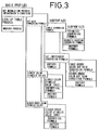
- Similarly, as shown in FIG. 5, the gamut mapping/appearance conversion profile group is composed of basic profiles representing (71) an LMN conversion process based on a combination of nonlinear conversion and 3 x 3 matrix conversion and (72) another process, one of which can be selected at a time, and subprofiles representing (81) an LMN conversion matrix, (82) a nonlinear conversion table, and (83) another table, one of which can be selected at a time with respect to the LMN conversion process. Variables relative to (91) an input range, (92) an output range, (93) a white point, and (94) a black point are established with respect to the nonlinear conversion table, using the parameters of the condition profiles of the printing/common color space conversion profile group, the gamut mapping/appearance conversion profile group, and the output device profile group (see "Reference Manual for Postscript", 2nd edition, published by ASCII Publishing Department).
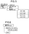
- If the
image output unit 14A is a color printer, then observing conditions of the gamut mapping/appearance conversion profile group are arranged as shown in FIG. 6. The observing conditions include parameters relative to an observing light source, and other parameters. - Data processing operation of the system for predicting a reproduced color image according to the present invention will be described below with reference to FIG. 7.
- First, the operator determines system configurations including the
image output unit 14B, the type of an original document on which a color image is recorded, an output medium, the type of inks used for recording a color image, and an output format, etc. in a step S1. - After the
image output unit 14B and other types are determined, the device profiles shown in FIGS. 3 through 6 are established using thedevice profile generator 18 in a step S2. These device profiles may be determined in advance depending on given devices before the system configurations of the reproduced color image predicting system are determined. - After the system configurations and the device profiles are determined, a common color space conversion table for converting YMCK halftone dot percentage data from the
image editor 12 into data in a common color space is generated in the commoncolor space converter 20 in a step S3. At this time, the selection of basic profiles and subprofiles depends on whether the parameters relative to these profiles are prepared in the condition profiles and whether these profiles are profiles which can cope with a requested processing speed. Therefore, not all the profiles are freely selected by the operator, but some of them are limited by prepared profiles. If no desired profiles have been established, then default values are selected. - The common color
space LUT generator 20 of theimage processor 16 successively selects a desired color reproduction process, etc., from the printing/common color space conversion profile group shown in FIGS. 3 and 4, and generates a common color space conversion table corresponding to theimage output unit 14B for producing a printed material based on the selected color reproduction process, etc. in the step S3. - To obtain a desired printed material from the
image output unit 14B, a color reproduction process of theimage output unit 14B is specified, and a basic formula depending on a desired accuracy and processing speed is selected. - If the
image output unit 14B is of the dot modulation output type, then the Neugebauer's equation which defines the relationship between the XYZ colorimetric system and the YMCK colorimetric system in the CIE common color space is selected as a color-predicting basic function from the basic profiles shown in FIG. 3. The Neugebauer's equation according to the equation (1) has variables classified into (1) the dot gain conversion formula (cX, mX, cXm, CXmy, etc.), (2) the single-color stimulus values (Xc, Xm, Xy, Xk, etc.), and (3) the higher-order color stimulus values (Xcm, Xcmy, Xcmyk, etc.), and desired subprofiles are selected for each of these sets of variables. - If the single conversion formula and the perimeter conversion formula are selected from the subprofiles with respect to the dot gain conversion formula, then the cX, mX, CXm, CXmy, etc. are replaced by the corrective formula according to the equation (2), and the parameters αp, αm, L thereof are given by the support layer profile and the ink profile of the printing output condition profiles shown in FIG. 4. The parameter αp is a variable depending on the paper on which a color image is to be printed. Typically, the parameter αp is set to 13 for art paper, 16 for coat paper, and 20 for wood-free paper. The parameter αm is a variable depending on the inks, and is set to 1 for average offset printing, and 1 or less when inks or printing conditions with a low dot gain are selected.
- If the quadratic equation conversion formula is selected from the subprofiles with respect to the single conversion formula, then the cX, mX, cXm, cXmy, etc. are replaced by the corrective formulas according to the equations (3) and (4), and the gains coefficients g₁ ∼ g₅ as their parameters are given by the support layer profile, the screen ruling/dot shape profile, and the ink profile of the printing output condition profiles shown in FIG. 4.
- The single conversion formula is employed for approximation when a common dot % value is used with respect to the X, Y, Z stimulus values. If different dot % values are used to correspond to the respective stimulus values X, Y, Z, then the accuracy of tristimulus values X, Y, Z that are obtained can further be increased.
- As described above, the single conversion formula is employed when a common dot % value is used with respect to the X, Y, Z stimulus values. If different dot % values are used to correspond to the respective X, Y, Z stimulus values for increased accuracy, then the XYZ independent conversion formula is selected from the subprofiles with respect to the dot gain conversion formula. At this time, the cX, mX, etc. are replaced by the corrective formulas according to the equation (5) or (6), and the cXm, cXmy, etc. are replaced by the corrective formula according to the equation (7). The parameters αpX, αpY, αpZ, αm, L, acXy, bxXy, the gain coefficients g₁ ∼ g₅ are given by the support layer profile, the screen ruling/dot shape profile, and the ink profile of the printing output condition profiles shown in FIG. 4. Since different dot gain corrective quantities are taken into account with respect to the X, Y, Z stimulus values, it is possible to obtain tristimulus values X, Y, Z which correspond very well to outputted YMCK halftone dot percentage data.
- If the single-color stimulus value table and the higher-order color stimulus value table are selected with respect to the single-color stimulus values and the higher-order color stimulus values, then tables relative to a given ink set and a given support layer are selected from the ink profile. If data of an ink set used in the printing output condition profile are not registered, then default values are selected from the standard profile.
- As described above, the parameters of the Neugebauer's equation according to the equation (1) are determined, and tristimulus values X, Y, Z are determined from the outputted dot % values using this conversion formula.
- The gamut mapping/
appearance LUT generator 22 of theimage processor 16 successively selects a desired color reproduction process, etc. from the gamut mapping/appearance conversion profile group shown in FIGS. 5 and 6, and equalizes the gamut mapping of theimage output unit 14B in the common color space with the gamut mapping of theimage output unit 14A in the common color space based on the selected color reproduction process, etc., and generates a gamut mapping/appearance conversion table for equalizing appearances corresponding to the visual adaptation in a step S4. In the generation of the gamut mapping/appearance conversion table, parameters corresponding to the observing light source are given from the observing condition profiles shown in FIG. 6 if theimage output unit 14A is a color printer. - The gamut mapping/appearance conversion table is generated according to the selected process as follows: For example, the LMN conversion formula suitable for the observing conditions with respect to the printed material and the type of the color image data is selected from the basic profiles, and the nonlinear conversion table is selected from the subprofiles for conversion from the CIE-XYZ colorimetric system into the LMN colorimetric system. The nonlinear conversion table is corrected with respect to the gamut mapping (the input range, the output range, etc.) and differences between observing conditions/color temperatures, and a conversion from the LMN colorimetric system into an L*M*N* colorimetric system is carried out. Finally, an inverse conversion from the L*M*N* colorimetric system into the XYZ colorimetric system is effected. A conversion table for conversion between the CIE colorimetric systems is stored as a gamut mapping/appearance conversion table in the data file 30.
- Then, the device color
space LUT generator 24 of theimage processor 16 generates a device color space conversion table for converting color image data in the common color space into color image data in the device color space of theimage output unit 14A, and stores the generated device color space conversion table in the data file 32 in a step S5. A known process using a look-up table is available for the conversion from color image data in the XYZ colorimetric system into color image data in the colorimetric system of a color printer or a CRT. For example, such a process is disclosed in "Printing CIELab imaging on CMYK printing", SPIE Vol. 1670 P316 (1992). If a plurality of output units including a color printer, a CRT, etc., are available, then it is possible to switch between a plurality of look-up tables. - The common color space LUT, the gamut mapping/appearance LUT, and the device color space LUT which have thus been generated are combined by the LUT combiner/
converter 26, or stored as individual LUTs in the data file 34 in a step S6. - After the above preparatory process has been completed, the operator operates the
image input unit 10 to read color image data of a color original document in a step S7. Theimage input unit 10 supplies the color image data as RGB data, for example, to theimage editor 12, which effects desired image processing on the RGB data, and supplies the processed RGB data as YMCK halftone dot percentage data to theimage processor 16 and theimage output unit 14B in a step S8. - The
image processor 16 converts the YMCK halftone dot percentage data supplied from theimage editor 12 with the conversion table that has been established with respect to theimage output unit converter 26 converts the YMCK halftone dot percentage data based on the common color space LUT, the gamut mapping/appearance LUT, and the device color space LUT, and stores the converted image data to theimage output unit 14A in a step S9. Specifically, in theimage processor 16, the YMCK halftone dot percentage data are converted into tristimulus values X, Y, Z in the common color space with the common color space LUT which defines the Neugebauer's equation (1) taking printing conditions into account, and thereafter the gamut mapping and appearances of theimage output units image output unit 14A with the device color space LUT. The color image data are then outputted as a hard copy or displayed on the CRT in a step S10. - The operator confirms the outputted/displayed color image in a step S11. If the operator sees no problem with respect to colors, etc., then the operator operates the
image output unit 14B to produce a printed material in a step S12. If there is a problem, then the color image data are processed again in theimage editor 12, and produced YMCK halftone dot percentage data are monitored by the reproduced color image predicting system repeatedly in the step S11. - In the above embodiment, as described above, YMCK halftone dot percentage data that are corrected taking into account a dot gain in a printed material are determined from YMCK halftone dot percentage data supplied to the
image output unit 14B, and the corrected YMCK halftone dot percentage data are converted into tristimulus values X, Y, Z, from which color image data to be displayed or outputted by theimage output unit 14A are obtained. In taking the dot gain into account, since the dot gain differs depending on the wavelength of illuminating light used for measurement, the YMCK halftone dot percentage data are corrected independently with respect to the tristimulus values X, Y, Z. Consequently, there are obtained tristimulus values X, Y, Z which are highly close to the conditions of the printed material. As a result, the predicted image produced by theimage output unit 14A and the printed image produced by theimage output unit 14B match each other very well. The operator can thus evaluate and confirm a reproduced color image highly accurately on a hard copy, a CRT, or the like before a printed material is finally produced. - Inasmuch as conversion formulas, corrective formulas, and parameters can be added or modified as desired with respect to the basic profiles, the subprofiles, and the condition profiles, the reproduced color image predicting system according to the present invention finds a range of applications which can easily be expanded, and can reproduce color images with increased accuracy.
- Although a certain preferred embodiment of the present invention has been shown and described in detail, it should be understood that various changes and modifications may be made therein without departing from the scope of the appended claims.
Claims (9)
- A system for predicting a reproduced color image in producing a color printed material from processed input color image data through a platemaking and printing process and outputting a color image corresponding to the color printed material, comprising:
printing condition profiles which represent printing conditions of the color printed material established as parameters;
data conversion profiles which represent color space data conversion formulas established for converting the processed input color image data into data in a color space of an image monitor device using the parameters represented by said printing condition profiles; and
converting means for converting the processed input color image data into the data in the color space of the image monitor device according to said color space data conversion formulas;
the arrangement being such that a color image corresponding to the color printed material can be displayed from the data in the color space. - A system according to claim 1, wherein said color space data conversion formulas comprise:
at least one first color space data conversion formula for converting the processed input color image data into data in a common color space using parameters represented by said printing condition profiles; and
at least one second color space data conversion formula for converting the data in the common color space into data in a device color space of the image monitor device. - A system according to claim 2, wherein the processed input color image data comprise data corresponding to an area ratio of an output image, and the data in the common color space comprise tristimulus values of a CIE colorimetric system, and wherein said first color space data conversion formula comprises a Neugebauer's equation for converting the data corresponding to the area ratio into the data in the common color space.
- A system according to claim 1, wherein said data conversion profiles comprise:
basic profiles representing at least one color space data conversion formula for converting the processed input color image data into the data in the color space; and
subprofiles representing selectable formulas and/or parameters corresponding to variables of said color space data conversion formula. - A method of predicting a reproduced color image in generating area modulation data of respective color materials from processed input color image data and producing a color printed material based on the area modulation data, comprising the steps of:
correcting the area modulation data based on dot gain correcting coefficients established for respective color representing coordinates of an image with respect to the respective color materials of the color printed material;
generating color image data of the color representing coordinates from the corrected area modulation data; and
displaying a color image corresponding to the color printed material based on the color image data of the color representing coordinates. - A method according to claim 5, wherein the color representing coordinates comprise tristimulus values X, Y, Z in a CIE-XYZ colorimetric system.
- A method according to claim 5, wherein the color representing coordinates comprise tristimulus values B, G, R in a BGR colorimetric system.
- A method according to claim 5, wherein the dot gain correcting coefficients include corrective terms depending on area modulation data of a color material other than the color materials.
- A system for predicting a reproduced color image in generating area modulation data of respective color materials from processed input color image data, producing a color printed material based on the area modulation data, and displaying a color image corresponding to the color printed material, comprising:
printing condition profiles which represent printing conditions established as parameters, the printing conditions including dot gain correcting coefficients established for respective color representing coordinates of an image with respect to the respective color materials of the color printed material;
corrective formula profiles which represent corrective formulas established for correcting the area modulation data based on the dot gain correcting coefficients; and
conversion formula profiles which represent conversion formulas established for converting the corrected area modulation data into color image data corresponding to the respective color representing coordinates;
the arrangement being such that color image data suitable for an image monitor device can be produced from the color image data corresponding to the respective color representing coordinates.
Applications Claiming Priority (6)
| Application Number | Priority Date | Filing Date | Title |
|---|---|---|---|
| JP28834493A JP3305070B2 (en) | 1993-11-17 | 1993-11-17 | Color image reproduction system |
| JP28834493 | 1993-11-17 | ||
| JP288344/93 | 1993-11-17 | ||
| JP773594 | 1994-01-27 | ||
| JP00773594A JP3510915B2 (en) | 1994-01-27 | 1994-01-27 | Color image reproduction method and system |
| JP7735/94 | 1994-01-27 |
Publications (3)
| Publication Number | Publication Date |
|---|---|
| EP0653879A2 true EP0653879A2 (en) | 1995-05-17 |
| EP0653879A3 EP0653879A3 (en) | 1996-02-28 |
| EP0653879B1 EP0653879B1 (en) | 2000-05-17 |
Family
ID=26342083
Family Applications (1)
| Application Number | Title | Priority Date | Filing Date |
|---|---|---|---|
| EP94118139A Expired - Lifetime EP0653879B1 (en) | 1993-11-17 | 1994-11-17 | Method of and system for predicting a colour reproduction image |
Country Status (3)
| Country | Link |
|---|---|
| US (1) | US5748858A (en) |
| EP (1) | EP0653879B1 (en) |
| DE (1) | DE69424507T2 (en) |
Cited By (12)
| Publication number | Priority date | Publication date | Assignee | Title |
|---|---|---|---|---|
| EP0817470A1 (en) * | 1996-07-02 | 1998-01-07 | Fujifilm Electronic Imaging Limited | Method and apparatus for generating a digital representation of an image |
| EP0881826A2 (en) * | 1997-05-27 | 1998-12-02 | Canon Kabushiki Kaisha | Image processing method, and image processing apparatus |
| EP1205880A2 (en) | 2000-06-16 | 2002-05-15 | Dainichiseika Color & Chemicals Mfg. Co. Ltd. | Computer colour matching system, method and recording medium |
| EP1356424A1 (en) * | 2000-12-18 | 2003-10-29 | Genoa Color Technologies Ltd. | Spectrally matched print proofer |
| EP1231772A3 (en) * | 2001-02-09 | 2005-06-29 | Seiko Epson Corporation | Output image adjustment for graphics files |
| US7268757B2 (en) | 2001-06-11 | 2007-09-11 | Genoa Color Technologies Ltd | Device, system and method for color display |
| US7352488B2 (en) | 2000-12-18 | 2008-04-01 | Genoa Color Technologies Ltd | Spectrally matched print proofer |
| DE10305046B4 (en) * | 2003-02-07 | 2009-04-09 | Heidelberger Druckmaschinen Ag | Method of generating a raster bitmap proof |
| US7714824B2 (en) | 2001-06-11 | 2010-05-11 | Genoa Color Technologies Ltd. | Multi-primary display with spectrally adapted back-illumination |
| US7999823B2 (en) | 2002-01-07 | 2011-08-16 | Samsung Electronics Co., Ltd. | Device and method for projection device based soft proofing |
| US8279481B2 (en) | 2002-05-07 | 2012-10-02 | Seiko Epson Corporation | Update control of image processing control data |
| US9953590B2 (en) | 2002-04-11 | 2018-04-24 | Samsung Display Co., Ltd. | Color display devices and methods with enhanced attributes |
Families Citing this family (37)
| Publication number | Priority date | Publication date | Assignee | Title |
|---|---|---|---|---|
| US6160635A (en) * | 1995-12-27 | 2000-12-12 | Fuji Photo Co., Ltd. | Color conversion method using ordered color signal interpolation |
| US6100999A (en) * | 1997-01-14 | 2000-08-08 | Fuji Xerox Co., Ltd. | Method for predicting color transfer characteristics |
| GB9813682D0 (en) | 1998-06-25 | 1998-08-26 | Fujifilm Electronic Imaging Li | Universal profiling |
| US6870636B2 (en) * | 1998-11-20 | 2005-03-22 | Canon Kabushiki Kaisha | Determining color mappings for a color printer |
| JP2000229397A (en) * | 1999-02-12 | 2000-08-22 | Riso Kagaku Corp | Color screen printing apparatus |
| US7119923B1 (en) * | 1999-07-23 | 2006-10-10 | Fuji Photo Film Co., Ltd. | Apparatus and method for image processing |
| US6480301B1 (en) | 1999-11-15 | 2002-11-12 | Lexmark International, Inc. | Method and apparatus for gamut boundary determination |
| US7106474B1 (en) * | 2000-03-31 | 2006-09-12 | Canon Kabushiki Kaisha | Color management system using measured device data |
| US6778300B1 (en) * | 2000-05-18 | 2004-08-17 | Canon Kabushiki Kaisha | Black generation for color management system |
| US7375857B1 (en) | 2000-09-22 | 2008-05-20 | Eastman Kodak Company | Print proofing with color and screen matching |
| EP1237354B1 (en) * | 2001-03-01 | 2013-08-14 | Epple Druckfarben AG | Print reproduction method |
| JP2002344761A (en) * | 2001-03-16 | 2002-11-29 | Seiko Epson Corp | Environment-adaptive image display system, projector, program, information storage medium, and image processing method |
| US8289266B2 (en) | 2001-06-11 | 2012-10-16 | Genoa Color Technologies Ltd. | Method, device and system for multi-color sequential LCD panel |
| JP4217398B2 (en) * | 2001-09-12 | 2009-01-28 | キヤノン株式会社 | Image data processing method, image data processing apparatus, storage medium, and program |
| US6786565B2 (en) * | 2001-09-24 | 2004-09-07 | Creo Americas, Inc. | Inkjet proofing with matched color and screen resolution |
| KR100441595B1 (en) * | 2001-10-15 | 2004-07-23 | 삼성전자주식회사 | Color conversion system and method using the same |
| JP2003324623A (en) * | 2002-05-08 | 2003-11-14 | Brother Ind Ltd | Color conversion apparatus, program and table in the same, and table preparing apparatus and program in the same |
| CN1717715A (en) | 2002-07-24 | 2006-01-04 | 吉诺彩色技术有限公司 | High brightness wide gamut display |
| JP4400706B2 (en) * | 2002-11-25 | 2010-01-20 | 富士ゼロックス株式会社 | Color data accuracy calculation method, color data accuracy calculation device, color processing method, color processing device, color data accuracy calculation program, color processing program, storage medium |
| US7342682B2 (en) * | 2002-12-05 | 2008-03-11 | Canon Kabushiki Kaisha | Incremental color transform creation |
| DE602004014250D1 (en) | 2003-01-28 | 2008-07-17 | Genoa Color Technologies Ltd | SUBPIXEL ARRANGEMENT FOR DISPLAYS MORE THAN THREE PRIMARY COLORS |
| US7339704B2 (en) * | 2003-06-19 | 2008-03-04 | Xerox Corporation | Method for standardizing input CMYK values for clustered printing environments |
| US8120812B2 (en) * | 2003-08-14 | 2012-02-21 | Xerox Corporation | System and method for obtaining color consistency for a color print job across multiple output devices |
| US7352491B2 (en) * | 2003-08-14 | 2008-04-01 | Xerox Corporation | System and method for selecting the best set of devices for rendering color documents |
| CN100445099C (en) * | 2003-12-12 | 2008-12-24 | 西铁城控股株式会社 | Exposure device |
| US7059701B2 (en) * | 2004-03-15 | 2006-06-13 | Lexmark International, Inc. | Method for calibrating production printing cartridges for use in an imaging system |
| US8587621B2 (en) | 2005-11-28 | 2013-11-19 | Genoa Color Technologies Ltd. | Sub-pixel rendering of a multiprimary image |
| US20070171441A1 (en) * | 2006-01-21 | 2007-07-26 | Iq Colour, Llc | Color and darkness management system |
| WO2007084566A2 (en) * | 2006-01-21 | 2007-07-26 | Iq Colour, Llc | Color and darkness management system |
| JP4183711B2 (en) * | 2006-01-31 | 2008-11-19 | 三菱重工業株式会社 | Color tone confirmation method and device before printing of printing press, plate making method, pattern color tone control method and device of printing press |
| US8233536B2 (en) * | 2007-01-23 | 2012-07-31 | Sharp Laboratories Of America, Inc. | Methods and systems for multiplication-free inter-layer image prediction |
| US8665942B2 (en) | 2007-01-23 | 2014-03-04 | Sharp Laboratories Of America, Inc. | Methods and systems for inter-layer image prediction signaling |
| US8503524B2 (en) * | 2007-01-23 | 2013-08-06 | Sharp Laboratories Of America, Inc. | Methods and systems for inter-layer image prediction |
| US7826673B2 (en) * | 2007-01-23 | 2010-11-02 | Sharp Laboratories Of America, Inc. | Methods and systems for inter-layer image prediction with color-conversion |
| US9694598B2 (en) * | 2010-05-24 | 2017-07-04 | Canon Kabushiki Kaisha | Image processing apparatus, ink jet printing apparatus, and image processing method |
| US9311890B2 (en) | 2013-09-03 | 2016-04-12 | Hewlett-Packard Development Company, L.P. | Assigning display colors to achieve apparent desired colors |
| JP6566830B2 (en) * | 2015-10-14 | 2019-08-28 | キヤノン株式会社 | Image verification apparatus and image verification method |
Citations (5)
| Publication number | Priority date | Publication date | Assignee | Title |
|---|---|---|---|---|
| GB2077548A (en) * | 1980-05-20 | 1981-12-16 | Ikegami Tsushinki Kk | Simulating colour printing process |
| FR2512974A1 (en) * | 1981-09-16 | 1983-03-18 | Dainippon Screen Mfg | METHOD FOR ALTERING THE COLORS OF AN IMAGE, DISPLAYED ON A COLOR DISPLAY, FOR REPRODUCING A COLOR PRINTED DOCUMENT |
| EP0173032A2 (en) * | 1984-08-28 | 1986-03-05 | Polaroid Corporation | Digital Color-Image Transformation |
| EP0243974A2 (en) * | 1986-05-01 | 1987-11-04 | Toppan Printing Co., Ltd. | Scanner set-up simulation apparatus |
| WO1990007837A1 (en) * | 1988-12-27 | 1990-07-12 | Eastman Kodak Company | Colour monitor for producing displays that visually match images as will be reproduced |
Family Cites Families (8)
| Publication number | Priority date | Publication date | Assignee | Title |
|---|---|---|---|---|
| US4500919A (en) * | 1982-05-04 | 1985-02-19 | Massachusetts Institute Of Technology | Color reproduction system |
| JPS58215653A (en) * | 1982-06-08 | 1983-12-15 | Dainippon Screen Mfg Co Ltd | Method and device for displaying reproduced color of multicolor printed matter |
| DE3347049C2 (en) * | 1983-12-24 | 1986-07-17 | Dr.-Ing. Rudolf Hell Gmbh, 2300 Kiel | Method and circuit arrangement for simulating multicolor printing on a color monitor |
| US4979032A (en) * | 1988-12-27 | 1990-12-18 | Eastman Kodak Company | Color imaging apparatus producing on various image receptive materials a visually matched hard copy reproduction of a video image displayed |
| BE1004659A5 (en) * | 1991-03-01 | 1993-01-05 | Barco Graphics Nv | METHOD AND APPARATUS FOR transforming a KLEURCOORDINATENSET. |
| US5309246A (en) * | 1991-09-18 | 1994-05-03 | Eastman Kodak Company | Technique for generating additional colors in a halftone color image through use of overlaid primary colored halftone dots of varying size |
| US5257097A (en) * | 1991-09-27 | 1993-10-26 | Eastman Kodak Company | Method and apparatus for selective interception of a graphics rendering operation for effecting image data modification |
| US5502580A (en) * | 1993-10-06 | 1996-03-26 | Fuji Photo Film Co., Ltd. | Color reproduction system |
-
1994
- 1994-11-17 EP EP94118139A patent/EP0653879B1/en not_active Expired - Lifetime
- 1994-11-17 DE DE69424507T patent/DE69424507T2/en not_active Expired - Lifetime
-
1996
- 1996-09-03 US US08/697,932 patent/US5748858A/en not_active Expired - Fee Related
Patent Citations (5)
| Publication number | Priority date | Publication date | Assignee | Title |
|---|---|---|---|---|
| GB2077548A (en) * | 1980-05-20 | 1981-12-16 | Ikegami Tsushinki Kk | Simulating colour printing process |
| FR2512974A1 (en) * | 1981-09-16 | 1983-03-18 | Dainippon Screen Mfg | METHOD FOR ALTERING THE COLORS OF AN IMAGE, DISPLAYED ON A COLOR DISPLAY, FOR REPRODUCING A COLOR PRINTED DOCUMENT |
| EP0173032A2 (en) * | 1984-08-28 | 1986-03-05 | Polaroid Corporation | Digital Color-Image Transformation |
| EP0243974A2 (en) * | 1986-05-01 | 1987-11-04 | Toppan Printing Co., Ltd. | Scanner set-up simulation apparatus |
| WO1990007837A1 (en) * | 1988-12-27 | 1990-07-12 | Eastman Kodak Company | Colour monitor for producing displays that visually match images as will be reproduced |
Cited By (19)
| Publication number | Priority date | Publication date | Assignee | Title |
|---|---|---|---|---|
| US5933254A (en) * | 1996-07-02 | 1999-08-03 | Fujifilm Electronic Imaging Ltd. | Method and apparatus for generating a digital representation of an image |
| EP0817470A1 (en) * | 1996-07-02 | 1998-01-07 | Fujifilm Electronic Imaging Limited | Method and apparatus for generating a digital representation of an image |
| EP0881826A2 (en) * | 1997-05-27 | 1998-12-02 | Canon Kabushiki Kaisha | Image processing method, and image processing apparatus |
| EP0881826A3 (en) * | 1997-05-27 | 1999-12-08 | Canon Kabushiki Kaisha | Image processing method, and image processing apparatus |
| US6643029B2 (en) | 1997-05-27 | 2003-11-04 | Canon Kabushiki Kaisha | Image processing method, image processing apparatus and computer readable memory |
| EP1205880A2 (en) | 2000-06-16 | 2002-05-15 | Dainichiseika Color & Chemicals Mfg. Co. Ltd. | Computer colour matching system, method and recording medium |
| EP1205880A3 (en) * | 2000-06-16 | 2004-12-15 | Dainichiseika Color & Chemicals Mfg. Co. Ltd. | Computer colour matching system, method and recording medium |
| US7352488B2 (en) | 2000-12-18 | 2008-04-01 | Genoa Color Technologies Ltd | Spectrally matched print proofer |
| EP1356424A1 (en) * | 2000-12-18 | 2003-10-29 | Genoa Color Technologies Ltd. | Spectrally matched print proofer |
| EP1356424A4 (en) * | 2000-12-18 | 2006-01-11 | Genoa Color Technologies Ltd | Spectrally matched print proofer |
| US8310498B2 (en) | 2000-12-18 | 2012-11-13 | Samsung Display Co., Ltd. | Spectrally matched print proofer |
| EP1231772A3 (en) * | 2001-02-09 | 2005-06-29 | Seiko Epson Corporation | Output image adjustment for graphics files |
| US7714824B2 (en) | 2001-06-11 | 2010-05-11 | Genoa Color Technologies Ltd. | Multi-primary display with spectrally adapted back-illumination |
| US7268757B2 (en) | 2001-06-11 | 2007-09-11 | Genoa Color Technologies Ltd | Device, system and method for color display |
| US9851599B2 (en) | 2001-06-11 | 2017-12-26 | Samsung Display Co., Ltd. | Color display device comprising at least six different primary colors |
| US7999823B2 (en) | 2002-01-07 | 2011-08-16 | Samsung Electronics Co., Ltd. | Device and method for projection device based soft proofing |
| US9953590B2 (en) | 2002-04-11 | 2018-04-24 | Samsung Display Co., Ltd. | Color display devices and methods with enhanced attributes |
| US8279481B2 (en) | 2002-05-07 | 2012-10-02 | Seiko Epson Corporation | Update control of image processing control data |
| DE10305046B4 (en) * | 2003-02-07 | 2009-04-09 | Heidelberger Druckmaschinen Ag | Method of generating a raster bitmap proof |
Also Published As
| Publication number | Publication date |
|---|---|
| EP0653879B1 (en) | 2000-05-17 |
| US5748858A (en) | 1998-05-05 |
| DE69424507T2 (en) | 2000-09-14 |
| EP0653879A3 (en) | 1996-02-28 |
| DE69424507D1 (en) | 2000-06-21 |
Similar Documents
| Publication | Publication Date | Title |
|---|---|---|
| EP0653879B1 (en) | Method of and system for predicting a colour reproduction image | |
| EP0648042B1 (en) | Colour reproduction system | |
| EP0660590B1 (en) | Image reproducing system | |
| EP0590921B1 (en) | Color printer calibration and printing method and corresponding printing system | |
| EP0854638B1 (en) | A method for continuous incremental color calibration for color document output terminals | |
| US7345798B2 (en) | Method of and apparatus for correcting color of print medium, and proofer used therein | |
| US5572632A (en) | Universal frame buffer for a rendering device | |
| US4992862A (en) | Color conversion display apparatus and method | |
| US6324975B1 (en) | Color correcting method | |
| US20030133138A1 (en) | Image processing method and apparatus | |
| JPH07281422A (en) | Color printing method wherein variable density gradation is expanded | |
| JPH0630251A (en) | Device and method for reproducing color image | |
| EP1343309A2 (en) | Method and system for calibrating a printing device | |
| US5781709A (en) | Method of and apparatus for generating proof | |
| EP1156666B1 (en) | Color-balanced TRC correction to compensate for illuminant changes in printer characterization | |
| JP3504975B2 (en) | Color reproduction system | |
| JP3612200B2 (en) | Printing gradation correction method and apparatus | |
| EP0703700B1 (en) | Method of and apparatus for predicting image | |
| EP0758181A2 (en) | A method for producing an original image data adjusting table for a proof printing system | |
| JP4046967B2 (en) | Image processing apparatus and method | |
| EP1596576A2 (en) | Method for closed loop characterization | |
| JPH10248017A (en) | Color calibration method | |
| JP3510915B2 (en) | Color image reproduction method and system | |
| JP3596584B2 (en) | Color conversion method | |
| JP4010756B2 (en) | Calibration method and apparatus |
Legal Events
| Date | Code | Title | Description |
|---|---|---|---|
| PUAI | Public reference made under article 153(3) epc to a published international application that has entered the european phase |
Free format text: ORIGINAL CODE: 0009012 |
|
| AK | Designated contracting states |
Kind code of ref document: A2 Designated state(s): DE FR GB |
|
| PUAL | Search report despatched |
Free format text: ORIGINAL CODE: 0009013 |
|
| AK | Designated contracting states |
Kind code of ref document: A3 Designated state(s): DE FR GB |
|
| 17P | Request for examination filed |
Effective date: 19960621 |
|
| 17Q | First examination report despatched |
Effective date: 19980401 |
|
| GRAG | Despatch of communication of intention to grant |
Free format text: ORIGINAL CODE: EPIDOS AGRA |
|
| GRAG | Despatch of communication of intention to grant |
Free format text: ORIGINAL CODE: EPIDOS AGRA |
|
| GRAH | Despatch of communication of intention to grant a patent |
Free format text: ORIGINAL CODE: EPIDOS IGRA |
|
| GRAH | Despatch of communication of intention to grant a patent |
Free format text: ORIGINAL CODE: EPIDOS IGRA |
|
| GRAA | (expected) grant |
Free format text: ORIGINAL CODE: 0009210 |
|
| AK | Designated contracting states |
Kind code of ref document: B1 Designated state(s): DE FR GB |
|
| REF | Corresponds to: |
Ref document number: 69424507 Country of ref document: DE Date of ref document: 20000621 |
|
| ET | Fr: translation filed | ||
| PLBE | No opposition filed within time limit |
Free format text: ORIGINAL CODE: 0009261 |
|
| STAA | Information on the status of an ep patent application or granted ep patent |
Free format text: STATUS: NO OPPOSITION FILED WITHIN TIME LIMIT |
|
| 26N | No opposition filed | ||
| REG | Reference to a national code |
Ref country code: GB Ref legal event code: IF02 |
|
| REG | Reference to a national code |
Ref country code: GB Ref legal event code: 732E |
|
| REG | Reference to a national code |
Ref country code: FR Ref legal event code: TP Ref country code: FR Ref legal event code: CD |
|
| PGFP | Annual fee paid to national office [announced via postgrant information from national office to epo] |
Ref country code: FR Payment date: 20131108 Year of fee payment: 20 Ref country code: GB Payment date: 20131113 Year of fee payment: 20 Ref country code: DE Payment date: 20131113 Year of fee payment: 20 |
|
| REG | Reference to a national code |
Ref country code: DE Ref legal event code: R071 Ref document number: 69424507 Country of ref document: DE |
|
| REG | Reference to a national code |
Ref country code: GB Ref legal event code: PE20 Expiry date: 20141116 |
|
| PG25 | Lapsed in a contracting state [announced via postgrant information from national office to epo] |
Ref country code: GB Free format text: LAPSE BECAUSE OF EXPIRATION OF PROTECTION Effective date: 20141116 |