EP0651969A2 - Blood pressure monitor system - Google Patents
Blood pressure monitor system Download PDFInfo
- Publication number
- EP0651969A2 EP0651969A2 EP94117553A EP94117553A EP0651969A2 EP 0651969 A2 EP0651969 A2 EP 0651969A2 EP 94117553 A EP94117553 A EP 94117553A EP 94117553 A EP94117553 A EP 94117553A EP 0651969 A2 EP0651969 A2 EP 0651969A2
- Authority
- EP
- European Patent Office
- Prior art keywords
- pressure
- pulse wave
- subject
- hdp
- pressing
- Prior art date
- Legal status (The legal status is an assumption and is not a legal conclusion. Google has not performed a legal analysis and makes no representation as to the accuracy of the status listed.)
- Granted
Links
Images


Classifications
-
- A—HUMAN NECESSITIES
- A61—MEDICAL OR VETERINARY SCIENCE; HYGIENE
- A61B—DIAGNOSIS; SURGERY; IDENTIFICATION
- A61B5/00—Measuring for diagnostic purposes; Identification of persons
- A61B5/02—Detecting, measuring or recording pulse, heart rate, blood pressure or blood flow; Combined pulse/heart-rate/blood pressure determination; Evaluating a cardiovascular condition not otherwise provided for, e.g. using combinations of techniques provided for in this group with electrocardiography or electroauscultation; Heart catheters for measuring blood pressure
- A61B5/021—Measuring pressure in heart or blood vessels
- A61B5/022—Measuring pressure in heart or blood vessels by applying pressure to close blood vessels, e.g. against the skin; Ophthalmodynamometers
- A61B5/0225—Measuring pressure in heart or blood vessels by applying pressure to close blood vessels, e.g. against the skin; Ophthalmodynamometers the pressure being controlled by electric signals, e.g. derived from Korotkoff sounds
Abstract
Description
- The present invention relates to a blood pressure monitor system which continuously measures intra-arterial blood pressure of a living subject and particularly relates to the art of improving the accuracy of blood pressure measurement.
- There has been proposed a blood pressure monitor system including a pressure sensor having a press surface and including one or more pressure sensing elements provided in the press surface; a pressing device which presses the pressure sensor against an arterial vessel of a living subject such as a patient via a body surface of the subject so that each pressure sensing element of the pressure sensor measures pressures at the body surface of the subject; pressing-force determining means for determining an optimum pressing force of the pressing device at which a portion of a wall of the artery is flattened under the pressure sensor pressed by the pressing device; and blood-pressure determining means for operating the pressing device to maintain the determined optimum pressing force and press the pressure sensor against the artery via the body surface or skin, and continuously determining intra-arterial blood pressure values of the artery, based on the pressure magnitudes or values measured by the pressure sensor at the body surface. An example of this monitor system is disclosed in U.S. Patent No. 5,119,822 or U.S. Patent No. 5,179,956.
- In the above-indicated prior monitor system, the pressure sensor is pressed against the artery via the body surface or skin, such that the wall of the artery is partly flattened under the pressure sensor. Since the pressure values measured by the pressure sensor through the flattened wall of the artery are free from adverse influences of the tensile forces produced in the arterial wall, they well reflect intra-arterial blood pressure values of the artery. According to this blood pressure measurement principle, the prior monitor system continuously measures the blood pressure of the subject by using the pressure sensor pressed at the optimum pressing force.
- Meanwhile, the experiments the present inventors conducted have elucidated that the blood pressure values continuously measured by the above-indicated prior monitor system tend to be higher than the blood pressure values measured using an inflatable cuff, and do not enjoy sufficiently high measurement accuracy. In this background, the present inventors have made various studies and experiments, and found that the soft and elastic subcutaneous tissue exists between the arterial vessel and the pressure sensor and that a "provisional" blood pressure measured by the pressure sensor, i.e., pressure sensing element positioned directly above the artery and pressed at the optimum pressing force contains both a "true" intra-arterial blood pressure of the artery and an "additional" pressure added thereto because of the elastic force of the subcutaneous tissue under the pressure sensor.
- It is therefore an object of the present invention to provide a blood pressure monitor system which continuously measures intra-arterial blood pressure of a living subject with high accuracy.
- The above object has been achieved by the present invention, which provides a blood pressure monitor system comprising: (a) a pressure sensor having a press surface and including at least one pressure sensing element provided in the press surface; (b) a pressing device which presses the pressure sensor against an arterial vessel of a living subject via a body surface of the subject so that the pressure sensing element of the pressure sensor measures a pressure value at the body surface of the subject; (c) pressing-force determining means for determining an optimum pressing force of the pressing device at which a portion of a wall of the arterial vessel of the subject is flattened under the pressure sensor pressed by the pressing device; (d) inflection-point determining means for changing pressing forces of the pressing device applied to the pressure sensor, and determining a point of inflection of a curve representing a relationship between the changed pressing forces of the pressing device and pressure values measured by the pressure sensor at the body surface of the subject; (e) correction-value determining means for determining a correction value based on the pressure value of the determined point of inflection; and (f) blood-pressure determining means for operating the pressing device to maintain the determined optimum pressing force and press the pressure sensor against the arterial vessel of the subject via the body surface of the subject, and continuously determining intra-arterial blood pressure values of the arterial vessel of the subject by subtracting the correction value from the pressure values measured by the pressure sensor at the body surface of the subject.
- In the blood pressure monitor system constructed as described above, the correction-value determining means determines a correction value based on the pressure value of the determined inflection point, and the blood-pressure determining means operates the pressing device to maintain the determined optimum pressing force and press the pressure sensor against the artery via the body surface or skin, and continuously determines intra-arterial blood pressure values of the artery by subtracting the correction value from the pressure values measured by the pressure sensor at the body surface. The correction value corresponds to the above-explained "additional" pressure added to the "true" intra-arterial blood pressure of the artery because of the elasticity of the subcutaneous tissue occurring between the artery and the pressure sensor. Since the additional pressure is removed by subtracting the correction value from the provisional blood pressure values measured by the pressure sensor, the present monitor system enjoys the sufficiently high accuracy of blood pressure measurement.
- In a preferred embodiment of the present invention, the correction-value determining means comprises: a memory which stores a plurality of pressure correcting curves each of which represents a relationship between correction values and pressing forces of the pressing device; selecting means for selecting one of the pressure correcting curves which provides a same difference between a first correction value corresponding to the pressing force of the determined point of inflection and a second correction value corresponding to the determined optimum pressing force of the pressing device, as an actual difference between the pressure value of the point of inflection and the pressure value corresponding to the optimum pressing force of the pressing device; and determining means for determining, as the correction value, the second correction value corresponding to the optimum pressing force of the pressing device, according to the selected one pressure correcting curve. Each of the pressure correcting curves represents a relationship between the pressing forces of the pressing device and the above-explained "additional" pressure values that increase because of the elasticity of the subcutaneous tissue as the pressing forces of the pressing device increase.
- The above and optional objects, features, and advantages of the present invention will be better understood by reading the following detailed description of the preferred embodiments of the invention when considered in conjunction with the accompanying drawings, in which:
- Fig. 1 is a diagrammatic view of a blood pressure monitor system embodying the present invention;
- Fig. 2 is a bottom view of a pulse wave sensor of the monitor system of Fig. 1;
- Fig. 3 is a flow chart representing a control program according to which a control device of the monitor system of Fig. 1 operates;
- Fig. 4 is a flow chart representing the correction value determine routine carried out at Step S4 of Fig. 3;
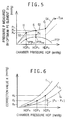
- Fig. 5 is a graph showing a curve, TDIA, representing a relationship between chamber pressure values, HDP, and provisional diastolic blood pressure values, PDIA, which curve is obtained at Step S4-1 of Fig. 4; and
- Fig. 6 is a graph showing a pressure correcting curve, fk, selected at Step S4-5 of Fig. 4.
-
- Referring to Figs. 1 and 2, there is shown a blood
pressure monitor system 8 embodying the present invention. In Fig. 1,reference numeral 10 designates a container-like housing which is open at one end thereof. Thehousing 10 is detachably set on awrist 16 of a living subject such as a patient, with a pair ofbands housing 10 is held in contact with a body surface orskin 12 of the subject. Apulse wave sensor 20 is secured to aflexible diaphragm 18 which is supported by inner surfaces of side walls of thehousing 10 and which closes the open end of thehousing 10, such that thepulse wave sensor 20 is displaceable relative to thehousing 10 and is advanceable out of the open end of thehousing 10. Thehousing 10,diaphragm 18, andpulse wave sensor 20 cooperate with each other to define apressure chamber 22 which is supplied with a pressurized fluid such as a pressurized air from anairsupplying device 24 via apressure regulator valve 26. Thus, thepulse wave sensor 20 is pressed against theskin 12 with a pressing force corresponding to an air pressure in the pressure chamber 22 (hereinafter, referred to as the "chamber pressure HDP"). In the present embodiment, thehousing 10,diaphragm 18, air-supplyingdevice 24,pressure regulator valve 26, and others cooperate with each other to provide a pressing device for pressing thepulse wave sensor 20 against theskin 12. An air-pressure sensor 27 is provided to measure the chamber pressure HDP. The air-pressure sensor 27 supplies a pressure signal, SP, representing the measured chamber pressure HDP, to acontrol device 32. - The
pulse wave sensor 20 shown in Fig. 2 includes a chip of a semiconductor material such as a monocrystalline silicon. A predetermined number of pressure sensing (PS) elements (e.g., thirty elements) 31 such as pressure sensing diodes are provided in an array in apress surface 28 of the semiconductor chip. With thepulse wave sensor 20 being pressed against theskin 12 in the above-described manner, the array ofPS elements 31 substantially perpendicularly intersects aradial artery 30 of thewrist 16, so that each of thePS elements 31 detects an oscillatory pressure wave, i.e., pressure pulse wave that is produced from theradial artery 30 in synchronism with heartbeats of the subject and is transmitted to the skin orbody surface 12. Theindividual PS elements 31 are spaced by sufficiently small distances from each other in the array thereof, so that a sufficiently large number ofPS elements 31 are positioned directly above theartery 30. The overall length of the array ofPS elements 31 is greater than the diameter or lumen of theartery 30. - The semiconductor chip of the
pulse wave sensor 20 has a thickness of about 300 microns (µm). An elongate recess (not shown) is formed in a back surface of the chip opposite to thepress surface 28, so that the chip has an elongate thin portion having a thickness of about several to ten and several microns (µm). In this elongate thin portion, the thirtyPS elements 31 are provided at regular intervals of distances, e.g., intervals of about 0.2 mm. EachPS element 31 is constituted by a resistance bridge including four strain-resisting elements produced by a well-known semiconductor manufacturing process such as diffusion or injection of impurities. The PS element or resistance bridge is disclosed in U.S. Patent No. 5,101,829 assigned to the Assignee of the present application. EachPS element 31 generates an electric signal whose magnitudes correspond to pressure magnitudes input thereto from theradial artery 30 via theskin 12, i.e., generates a pulse wave signal, SM, representing the pressure pulse wave produced from theartery 30. The pulse wave signal SM is supplied to thecontrol device 32. - The
control device 32 includes a microcomputer comprised of a central processing unit (CPU) 34, a read only memory (ROM) 36, and a random access memory (RAM) 38. TheCPU 34 processes input signals according to control programs pre-stored in theROM 36 by utilizing a temporary-storage function of theRAM 38. Specifically described, theCPU 34 determines an optimum chamber pressure, HDPS, as an optimum pressing force to be applied to thepulse wave sensor 20, and selects anoptimum PS element 31a from the thirtyPS elements 31, each based on the pulse wave signals SM supplied from the thirtyPS elements 31 to thecontrol device 32 while the chamber pressure HDP is continuously increased. TheCPU 34 controls thepressure regulator valve 26 to hold the chamber pressure HDP at the thus determined optimum value HDPS and thereby obtain a pressure pulse wave of the subject as the pulse wave signal SM supplied from the thus selectedoptimum PS element 31a pressed with the optimum pressure HDPS. TheCPU 34 controls anoutput device 40 to display a waveform representing intra-arterial blood pressure values, PBP, of theradial artery 30, and record the same on a record sheet (not shown), each based on the pulse wave signal SM supplied from theoptimum PS element 31a. An upper peak and a lower peak of each of successive pulses of the waveform displayed and recorded by theoutput device 40 correspond to a systolic blood pressure, PSYS, and a diastolic blood pressure, PDIA, in theartery 30. Theoutput device 40 displays, in digits, the systolic and diastolic blood pressure values PSYS, PDIA for each one pulse, and additionally displays, using points or other symbols, respective time-wise changes of the systolic and diastolic blood pressure values PSYS, PDIA for the successive pulses. - When the
radial artery 30 under theskin 20 is pressed by thepulse wave sensor 20 with the optimum chamber pressure HDPS, a portion of the wall of theartery 30 is flattened as shown in Fig. 1. Pressure magnitudes or values, P, measured by thepulse wave sensor 20 through the flattened wall of theartery 30 are free from adverse influences of the tensile forces produced in the wall of theartery 30, and accordingly they reflect the intra-arterial blood pressure values of theartery 30. According to this blood pressure measurement principle, thecontrol device 32 controls thepresent monitor system 8 to continuously measure the blood pressure values PBP in theartery 30 of the subject. - The various functions of the present blood
pressure monitor system 8 for carrying out the continuous blood pressure measurement of a living subject are summarized as follows: Thepulse wave sensor 20 functioning as a pressure sensor is pressed, at the optimum chamber pressure HDPS, i.e., optimum pressing force of thepressing device control device 32 functioning as pressing-force determining means, against theradial artery 30 under the body surface orskin 12 of the subject. Thecontrol device 32 also functions as inflection-point determining means for determining a point of inflection, H, of a curve, TDIA, representing a relationship between "provisional" diastolic blood pressure values PDIA measured by thepulse wave sensor 20 and chamber pressure values HDP measured by the air-pressure sensor 27 while the chamber pressure HDP is continuously changed by thecontrol device 32 as the pressing-force determining means. Thecontrol device 32 also functions as correction-value determining means for determining a correction value, KS, based on a provisional diastolic blood pressure value, PH, of the determined point of inflection H. Thecontrol device 32 further functions as blood-pressure determining means for determining a "true" intra-arterial blood pressure value PBP of theartery 30 by subtracting the determined correction value KS from each provisional blood pressure value, Pa, measured by the pulse wave sensor,i.e. pressure sensor 20 pressed at the optimum chamber pressure HDPS, i.e., optimum pressing force of thepressing device - Hereinafter, there will be described the blood pressure measuring operation of the
present monitor system 8, by reference to the flow charts of Figs. 3 and 4. - Upon application of electric power to the
present monitor system 8, an initialization step (not shown) is carried out. Then, if a start/stop button (not shown) is operated, theCPU 34 of thecontrol device 32 starts with Step S1 to judge whether a flag, F, is set at "1", i.e., F=1. That the flag F is set at F=1 means that the optimum chamber pressure HDPS and theoptimum PS element 31a have been determined and selected. - Assuming that a negative judgment is made at Step S1, the control of the
CPU 34 goes to Step S2 to determine the optimum chamber pressure HDPS and subsequently to Step S3 to select theoptimum PS element 31a. For example, these operations are carried out in the following manner: After the chamber pressure HDP has been decreased down to a sufficiently low level by controlling thepressure regulator valve 26 and thereby discharging the air from thepressure chamber 22, the chamber pressure HDP is slowly increased up to a predetermined level at a suitable rate of change, so that thepulse wave sensor 20 is pressed with the increasing pressing forces against theradial artery 30 via theskin 12. During this pressing force increasing operation, theCPU 34 reads in the respective pulse wave signals SM supplied from theindividual PS elements 31 of thepulse wave sensor 20, together with the pressure signal SP supplied from the air-pressure sensor 27. As described above, the pressure signal SP represents the slow and monotonous increasing of the chamber pressure HDP of thepressure chamber 22. TheCPU 34 calculates, from each of the thus obtained pulse wave signals SM, the amplitude of each of successive pulses corresponding to heartbeats of the subject and selects, as theoptimum PS element 31a, one of the thirtyPS elements 30 which has detected a maximum pulse having the greatest amplitude of all the calculated amplitudes. The amplitude of each pulse is calculated by subtracting the magnitude of the lower peak of each pulse from the magnitude of the upper peak of the same pulse. TheCPU 34 additionally determines, as the optimum chamber pressure HDPS, a chamber pressure HDP at the time when the maximum pulse has been detected by theoptimum PS element 31a. The thus determined optimum chamber pressure HDPS is stored in theRAM 38. In the graph of Fig. 5, the optimum chamber pressure HDPS corresponds to an upper peak, PTPmax, of a curve, PTP, representing the change of the respective amplitudes of the successive pulses of the pressure pulse wave represented by the pulse wave signal SM supplied from theoptimum PS element 31a. - Step S3 is followed by Step S4, i.e., correction value determine routine shown in Fig. 4. First, at Step S4-1 of the flow chart of Fig. 4, the
CPU 34 determines a curve TDIA, indicated at solid line in Fig. 5, which represents a relationship between the provisional diastolic blood pressure values PDIA measured by thepulse wave sensor 20 and the chamber pressure values HDP measured by the air-pressure sensor 27 while the chamber pressure HDP is continuously increased at Step S2 under the control of theCPU 34. The curve TDIA is obtained by smoothly connecting the respective lower-peak points of the successive pulses of the pressure pulse wave represented by the pulse wave signal SM supplied from theoptimum PS element 31a. - The curve TDIA includes an increasing
portion 50, and alevel portion 52 called "plateau" which appears following the increasingportion 50 during the chamber pressure increasing operation carried out at Step S2. Subsequently, at Step S4-2, theCPU 34 determines an inflection point H connecting the increasingportion 50 and thelevel portion 52 of the curve TDIA. For example, the inflection point H is determined by identifying a point where the slopes (i.e., differential values) of the curve TDIA significantly largely decreases, i.e., identifying an upper-peak point of a curve representing the change of slopes of the curve TDIA, according to an algorithm prestored in theROM 36. At the following Step S4-3, theCPU 34 stores, in theRAM 38, a provisional diastolic blood pressure value PH and a chamber pressure value HDPH of the thus determined inflection point H. Step S4-3 is followed by Step S4-4 to determine a point, S, of the curve TDIA corresponding to the stored optimum chamber pressure HDPS and store, in theRAM 38, a provisional blood pressure value PS corresponding to the thus determined point S. - Subsequently, the control of the
CPU 34 goes to Step S4-5 to select one of a plurality of relationships, K = fn(HDP) where n = 1, 2, 3, ..., m), pre-stored in theROM 36, in such a manner that the selected one relationship, K = fk(HDP), indicated at solid line in Fig. 6, provides the same difference, KS - KH, between a correction value, KS, corresponding to the stored optimum chamber pressure value HDPS and a correction value, KH, corresponding to the stored chamber pressure value HDPH, as the difference, PS - PH, between the stored pressure values PS, PH corresponding to the points S, H, respectively. Step S4-5 is followed by Step S4-6 to determine the correction value KS corresponding to the stored optimum chamber pressure value HDPS, according to the thus selected relationship, i.e., pressure correcting curve
pulse wave sensor 20 to theradial artery 30 with theskin tissue 12 being removed. - The pressure correcting curve

subcutaneous tissue 12 located between theradial artery 12 and the pulse wave sensor 20 (i.e., each PS element 31). The additional pressure values increase as the chamber pressure values HDP increase, as shown in Fig. 6. This relationship


- The pressure value determine routine of Step S4 is followed by Step S5 of Fig. 3. At this step, the
CPU 34 sets the flag F to F=1. Subsequently, the control of theCPU 34 goes to Step S6 to control thepressure regulator valve 26 so as to press thepulse wave sensor 20 at the optimum chamber pressure HDPS. Thus, the optimum chamber pressure HDPS is maintained at the optimum value HDPS. Step S6 is followed by Step S7 to judge whether theCPU 34 receives, from theoptimum PS element 31a, a length or amount of the pulse wave signal SM representing one pulse corresponding to one heartbeat of the subject. Steps S8 and S9 are not carried out so long as a negative judgment is made at Step S7. If a positive judgment is made at this step, the control of theCPU 34 goes to Step S8 to calculate a "true" blood pressure value PBP of the subject, according to the following, pressure correcting expression (1):

TheCPU 34 determines the "true" or intra-arterial blood pressure value PBP of theartery 30 by subtracting the determined correction value
pulse wave sensor 20 oroptimum PS element 31a pressed at the optimum chamber pressure HDPS. The thus determined blood pressure value PBP is stored in theRAM 38. The true blood pressure values PBP are continuously determined and stored in very short sampling cycles, so as to provide a corrected pulse wave which changes in synchronism with the heartbeats of the subject. TheCPU 34 determines, as systolic and diastolic blood pressure values, PSYS and PDIA, the respective blood pressure values of the upper and lower peaks of each of successive pulses of the corrected pulse wave, according to a well-known algorithm pre-stored in theROM 36. The thus determined systolic and diastolic blood pressure values PSYS and PDIA are stored in theRAM 38. - Subsequently, the control of the
CPU 34 goes to Step S9 to control theoutput device 40 to display the waveform of the corrected pulse wave, i.e., "true" blood pressure values PBP obtained at Step S8 of the current control cycle, following the waveform which had been obtained at Step S8 in the control cycles prior to the current control cycle. In addition, theoutput device 40 is operated to display, in digits, the systolic and diastolic blood pressure values PSYS, PDIA determined at Step S8, and add a point (or symbol) representing each of the values PSYS, PDIA to a corresponding one of respective time-wise changes of the points (or symbols) PSYS, PDIA. - It emerges from the foregoing description that, in the present embodiment, Step S4-2 and a portion of the control device 32 for carrying out Step S4-2 function as the inflection-point determining means for determining the inflection point H of the curve TDIA representing the relationship between the pressing forces HDP of the pressing device 10, 18, 24, 26 and the provisional blood pressure values Pa measured by the pulse wave sensor 20 as the pressure sensor while the pressing forces or chamber pressure values HDP are continuously changed, that Step S4-6 and a portion of the control device 32 for carrying out Step S4-6 function as the correction-value determining means for determining the correction value KS based on the provisional blood pressure value PH measured by the pulse wave sensor 20 and corresponding to the determined inflection point H, and that Step S8 and a portion of the control device 32 for carrying out Step S8 function as the blood-pressure determining means for operating the pressing device 10, 18, 24, 26 to maintain the optimum pressing force or chamber pressure HDPS and thereby press the pulse wave sensor 20 against the radial artery 30 and continuously determining the true intra-arterial blood pressure values PBP of the artery 30 by subtracting the correction value KS from the provisional blood pressure values Pa measured by the pulse wave sensor 20 at the body surface or skin 12 of the subject.
- Since the soft and elastic
subcutaneous tissue 12 exists between theradial artery 30 and thepulse wave sensor 20, the provisional blood pressure value Pa measured by theoptimum PS selement 31a positioned directly above theartery 30 and pressed at the optimum pressing force HDPS contains both the true intra-arterial blood pressure value PBP of theartery 30 and the additional pressure value increased by the elastic force of thesubcutaneous tissue 12. However, in the present bloodpressure monitor system 8, the true intra-arterial blood pressure value PBP of theartery 30 is determined with high accuracy by subtracting, from the provisional blood pressure value Pa measured by thepulse wave sensor 20, the correction value KS approximating the additional pressure resulting from the elastic force of thesubcutaneous tissue 12. - While the present invention has been described in its preferred embodiment, the present invention may otherwise be embodied.
- For example, although in the illustrated embodiment the inflection point H of the curve TDIA is determined at Step S4-2 and the correction value KS is determined based on the pressure value PH of the inflection point H at S4-6, it is possible to determine, as an inflection point of the curve TDIA, a point, G, connecting the
level portion 52 and a second increasingportion 54 at Step S4-2, and determine a correction value KS based on a pressure value, PG, of the inflection point G at Step S4-6. In the latter case, at Step S4-5, theCPU 34 selects one of the pressure correcting curves

- While both in the illustrated embodiment and the above-indicated modified embodiment the curve TDIA is obtained to determine the inflection point H or G at Step S4-1, it is possible to obtain, at Step S4-1, a curve TSYS by smoothly connecting the respective upper-peak points of successive pulses of the pressure pulse wave represented by the pulse wave signal SM supplied from the
optimum PS element 31a. In the latter case, an inflection point corresponding to the point H or G is determined on the curve TSYS at Step S4-2, and a correction value KS is determined based on a provisional blood pressure value P of the determined inflection point. - In the illustrated embodiment, at Step S2, the optimum pressing force or chamber pressure HDPS is determined by identifying the pressing force or chamber pressure HDP at the time of detection of the maximum pulse by the
optimum PS element 31a of thepulse wave sensor 20. It is known that the pressing force HDP at the time of detection of the maximum pulse well corresponds to the middle point of thelevel portion 52 of the curve TDIA. Therefore, at Step S2, it is possible to identify the middle point of thelevel portion 52 of the curve TDIA and determine a pressing force or chamber pressure HDP of the identified middle point, as the optimum pressing force or chamber pressure HDPS. - In the illustrated embodiment, at Step S4-2, the inflection point H of the curve TDIA is determined by identifying a point where the slopes of the curve TDIA significantly largely changes. However, it is possible to determine the inflection point H of the curve TDIA by identifying a point, PTPH, of the pulse-amplitude curve PTP, as shown in Fig. 5. The point PTPH has an amplitude smaller by a predetermined proportion (e.g., about 10%) than the maximum amplitude PTPmax of the curve PTP, and corresponds to a pressing force HDP smaller than the optimum pressing force HDPS. In this case, the inflection point H of the curve TDIA corresponds to the pressing force HDP of the point PTPH.
- In the illustrated embodiment, at Step S4, the pressure correcting curves


- While in the illustrated embodiment Step S7 is provided, before Steps S8 and S9, to wait for supplying of each one pulse of the pulse wave signal SM, i.e., pressure pulse wave, Step S7 may be omitted.
- It is to be understood that the present invention may be embodied with other changes, improvements, and modifications that may occur to those skilled in the art without departing from the spirit and scope of the present invention defined in the appended claims.
Claims (13)
- A blood pressure monitor system (8) comprising:
a pressure sensor (20) having a press surface (28) and including at least one pressure sensing element (31) provided in said press surface;
a pressing device (10, 18, 24, 26) which presses said pressure sensor (20) against an arterial vessel (30) of a living subject via a body surface (12) of the subject so that said pressure sensing element (31) of the pressure sensor measures a pressure value at said body surface of the subject;
pressing-force determining means (32, S2) for determining an optimum pressing force (HDPS) of said pressing device (14, 18, 24, 26) at which a portion of a wall of said arterial vessel (30) of the subject is flattened under said pressure sensor (20) pressed by the pressing device;
inflection-point determining means (32, S4-2) for changing pressing forces of said pressing device (14, 18, 24, 26) applied to said pressure sensor (20), and determining a point of inflection (H) of a curve (TDIA) representing a relationship between the changed pressing forces of the pressing device and pressure values measured by the pressure sensor at said body surface (12) of the subject;
correction-value determining means (32, S4-6) for determining a correction value (KS) based on the pressure value (PH) of the determined point of inflection (H); and
blood-pressure determining means (32, S8) for operating said pressing device (10, 18, 24, 26) to maintain the determined optimum pressing force (HDPS) and press said pressure sensor (20) against said arterial vessel (30) of the subject via said body surface (12) of the subject, and continuously determining intra-arterial blood pressure values of the arterial vessel of the subject by subtracting said correction value (KS) from the pressure values (P) measured by the pressure sensor at the body surface of the subject. - A monitor system according to claim 1, wherein said correction-value determining means comprises:
a memory (36) which stores a plurality of pressure correcting curves (fn) each of which represents a relationship between correction values (K) and pressing forces (HDP) of said pressing device (14, 18, 24, 26);
selecting means (32, S4-5) for selecting one (fk) of said pressure correcting curves (fn) which provides a same difference between a first correction value (KH) corresponding to the pressing force (HDPH) of said determined point of inflection (H) and a second correction value (KS) corresponding to said determined optimum pressing force (HDPS) of said pressing device, as an actual difference between the pressure value (PH) of said point of inflection and the pressure value (PS) corresponding to said optimum pressing force of the pressing device; and
determining means (32, S4-6) for determining, as said correction value, said second correction value (KS) corresponding to said optimum pressing force (HDPS) of the pressing device (10, 18, 24, 26), according to the selected one pressure correcting curve (fk). - A monitor system according to claim 2, wherein said memory (36) of said correction-value determining means stores said pressure correcting curves (fn) each of which is defined by a quadratic function.
- A monitor system according to claim 2, wherein said memory (36) of said correction-value determining means stores said pressure correcting curves each of which is defined by a linear function.
- A monitor system according to any of claims 1 to 4, wherein said pressure sensor comprises a pulse wave sensor (20) which has said press surface (28) and which detects a pressure pulse wave including a plurality of successive pulses produced from said arterial vessel (30) of said subject in synchronism with heartbeats of the subject and transmitted to said press surface of said pulse wave sensor via said body surface (12) of the subject.
- A monitor system according to claim 5, wherein said pulse wave sensor (20) comprises a semiconductor chip having said press surface (28), and a plurality of pressure sensing elements (31) as said at least one pressure sensing element, said pressure sensing elements being provided in an array in said press surface of said semiconductor chip, said array of pressure sensing elements being adapted to intersect said arterial vessel (30) of the subject with said pulse wave sensor being pressed against the arterial vessel of the subject via said body surface (12) of the subject.
- A monitor system according to claim 5 or claim 6, wherein said pressing device comprises:
a housing (10) having an open end;
a flexible diaphragm (18) closing said open end of said housing (10) and thereby defining a fluid-tight chamber (22) in the housing, said pressure sensor (20) being secured to an outer surface of said diaphragm;
a fluid supply (24) which supplies a pressurized fluid to said fluid-tight chamber (22) of said housing (10) to press said pulse wave sensor (20) against said arterial vessel (30) of said subject via said body surface (12) of the subject; and
a pressure regulator (26) which regulates a fluid pressure in said fluid-tight chamber (22) of said housing (10). - A monitor system according to claim 7, wherein said pressing-force determining means comprises:
a fluid-pressure sensor (27) which measures said fluid pressure in said fluid-tight chamber (22) of said housing (10); and
means (32, S2) for determining, as said optimum pressing force of said pressing device (10, 18, 24, 26), the fluid pressure (HDPS) measured by said fluid-pressure sensor (27) at a time when said pulse wave sensor (20) has detected a maximum pulse having a greatest amplitude (PTPmax) of the successive pulses of said pressure pulse wave detected by the pulse wave sensor while said fluid pressure of said fluid-tight chamber (22) is continuously changed. - A monitor system according to any of claims 5 to 8, wherein said inflection-point determining means comprises means (32, S4-1) for determining, as said curve, a curve (TDIA) representing a relationship between said changed pressing forces (HDP) of said pressing device (10, 18, 24, 26) and provisional diastolic blood pressure values (P) measured by said pulse wave sensor (20) at said body surface (12) of said subject, said provisional diastolic blood pressure values corresponding to respective lower peaks of the successive pulses of said pressure pulse wave detected by the pulse wave sensor while the pressing force of the pressing device is continuously changed.
- A monitor system according to any of claims 5 to 8, wherein said inflection-point determining means comprises means (32) for determining, as said curve, a curve representing a relationship between said changed pressing forces (HDP) of said pressing device (10, 18, 24, 26) and provisional systolic blood pressure values measured by said pulse wave sensor (20) at said body surface (12) of said subject, said provisional systolic blood pressure values corresponding to respective upper peaks of the successive pulses of said pressure pulse wave detected by the pulse wave sensor while the pressing force of the pressing device is continuously changed.
- A monitor system according to any of claims 1 to 10, wherein said inflection-point determining means comprises means (32, S4-2) for determining, as said point of inflection, a point (H) of said curve (TDIA) where slopes of the curve significantly largely change.
- A monitor system according to any of claims 5 to 11, wherein said blood-pressure determining means comprises means (32, S8) for successively determining, as said intra-arterial blood pressure values of said arterial vessel (30) of said subject, at least one of a systolic and a diastolic blood pressure value by subtracting said correction value (KS) from at least one of provisional systolic and diastolic blood pressure values (P) corresponding to the upper and lower peaks of each of the successive pulses of said pressure pulse wave detected by said pulse wave sensor (20).
- A monitor system according to claim 12, further comprising an output device (40) including at least one of (a) a display which displays at least one of (i) digits representing each of the successively determined values of said at least one of said systolic and diastolic blood pressure, (ii) symbols representing a time-wise change of said successively determined values of said at least one of said systolic and diastolic blood pressure, (iii) a waveform of the continuously determined intra-arterial blood pressure, and (b) a recorder which records, on a recording medium, at least one of (i) digits representing each of the successively determined values of said at least one of said systolic and diastolic blood pressure, (ii) symbols representing a time-wise change of said successively determined values of said at least one of said systolic and diastolic blood pressure, (iii) a waveform of the continuously determined intra-arterial blood pressure.
Applications Claiming Priority (3)
| Application Number | Priority Date | Filing Date | Title |
|---|---|---|---|
| JP27866193A JP3241510B2 (en) | 1993-11-08 | 1993-11-08 | Continuous blood pressure measurement device |
| JP278661/93 | 1993-11-08 | ||
| JP27866193 | 1993-11-08 |
Publications (3)
| Publication Number | Publication Date |
|---|---|
| EP0651969A2 true EP0651969A2 (en) | 1995-05-10 |
| EP0651969A3 EP0651969A3 (en) | 1997-04-16 |
| EP0651969B1 EP0651969B1 (en) | 2000-05-03 |
Family
ID=17600399
Family Applications (1)
| Application Number | Title | Priority Date | Filing Date |
|---|---|---|---|
| EP94117553A Expired - Lifetime EP0651969B1 (en) | 1993-11-08 | 1994-11-07 | Blood pressure monitor system |
Country Status (4)
| Country | Link |
|---|---|
| US (1) | US5439002A (en) |
| EP (1) | EP0651969B1 (en) |
| JP (1) | JP3241510B2 (en) |
| DE (1) | DE69424252T2 (en) |
Cited By (4)
| Publication number | Priority date | Publication date | Assignee | Title |
|---|---|---|---|---|
| US6432061B1 (en) | 1997-09-12 | 2002-08-13 | Polar Electro Oy | Method and arrangement for measuring venous pressure |
| US6443905B1 (en) | 1997-09-12 | 2002-09-03 | Polar Electro Oy | Method and arrangement for blood pressure measurement |
| US6554773B1 (en) | 1997-09-12 | 2003-04-29 | Polar Electro Oy | Method and arrangement for blood pressure measurement |
| EP1769739A2 (en) | 2005-09-29 | 2007-04-04 | Wolfgang Egner | Blood pressure measurement device and method |
Families Citing this family (20)
| Publication number | Priority date | Publication date | Assignee | Title |
|---|---|---|---|---|
| IL123242A0 (en) * | 1998-02-09 | 1998-09-24 | Optelmed Ltd | Method and device for arterial blood pressure measurement |
| US6491647B1 (en) | 1998-09-23 | 2002-12-10 | Active Signal Technologies, Inc. | Physiological sensing device |
| US6394959B1 (en) * | 2000-07-05 | 2002-05-28 | Colin Corporation | Continuous blood-pressure monitor apparatus |
| WO2005089642A1 (en) | 2004-03-24 | 2005-09-29 | Dainippon Sumitomo Pharma Co., Ltd. | Garment for bioinformation measurement having electrode, bioinformation measurement system and bioinformation measurement device, and device control method |
| WO2005089645A1 (en) * | 2004-03-24 | 2005-09-29 | Dainippon Sumitomo Pharma Co., Ltd. | Biological information measuring garment having sensor, biological information measuring system and equipment, and control method of equipment |
| US20050277838A1 (en) * | 2004-06-15 | 2005-12-15 | Sysmex Corporation | Noninvasive biometric measuring device |
| DE102004062435A1 (en) * | 2004-12-20 | 2006-06-29 | Braun Gmbh | Method and device for non-invasive detection of the blood flow and dependent parameters in arteries, in particular the arterial waveform and the blood pressure |
| EP2020911A4 (en) | 2006-05-13 | 2011-07-27 | Tensys Medical Inc | Continuous positioning apparatus and methods |
| US20080021334A1 (en) * | 2006-07-19 | 2008-01-24 | Finburgh Simon E | Apparatus and methods for non-invasively measuring hemodynamic parameters |
| US8777862B2 (en) | 2007-10-12 | 2014-07-15 | Tensys Medical, Inc. | Apparatus and methods for non-invasively measuring a patient's arterial blood pressure |
| KR101504600B1 (en) | 2008-11-06 | 2015-03-23 | 삼성전자주식회사 | Apparatus and method for measuring blood pressure |
| KR101800705B1 (en) | 2009-04-28 | 2017-12-21 | 삼성전자 주식회사 | Blood pressure monitoring apparatus and method for correcting error of blood pressure |
| JP6366463B2 (en) | 2014-10-31 | 2018-08-01 | オムロンヘルスケア株式会社 | Blood pressure measurement device |
| JP6366462B2 (en) | 2014-10-31 | 2018-08-01 | オムロンヘルスケア株式会社 | Blood pressure measurement device |
| JP6385244B2 (en) | 2014-10-31 | 2018-09-05 | オムロンヘルスケア株式会社 | Blood pressure measuring device |
| JP6228557B2 (en) * | 2015-02-27 | 2017-11-08 | オムロンヘルスケア株式会社 | Biological information measuring device |
| JP6586818B2 (en) | 2015-08-21 | 2019-10-09 | オムロンヘルスケア株式会社 | Medical support device, medical support method, medical support program, biological information measuring device |
| JP6631121B2 (en) | 2015-09-18 | 2020-01-15 | オムロンヘルスケア株式会社 | Blood pressure analysis device, blood pressure measurement device, operation method of blood pressure analysis device, blood pressure analysis program |
| JP6164309B2 (en) | 2016-01-04 | 2017-07-19 | オムロンヘルスケア株式会社 | machine |
| JP6834192B2 (en) | 2016-06-28 | 2021-02-24 | オムロンヘルスケア株式会社 | Biological information measuring device, operating method of biological information measuring device, and operating program of biological information measuring device |
Citations (6)
| Publication number | Priority date | Publication date | Assignee | Title |
|---|---|---|---|---|
| US4105021A (en) * | 1976-08-13 | 1978-08-08 | Joseph H. Allen | Method and arrangement for measuring blood pressure |
| EP0246571A1 (en) * | 1986-05-15 | 1987-11-25 | OMRON Corporation | Electronic blood pressure meter incorporating compensation function for systolic and diastolic blood pressure determinations |
| WO1988003387A1 (en) * | 1986-11-06 | 1988-05-19 | Sri International | Blood pressure monitoring method and apparatus |
| US4836213A (en) * | 1988-02-25 | 1989-06-06 | Nippon Colin Co., Ltd. | Pressure control system for continuous blood pressure monitor transducer |
| US5119822A (en) * | 1988-10-19 | 1992-06-09 | Colin Electronics Co., Ltd. | Pulse wave detecting apparatus |
| FR2700683A1 (en) * | 1993-01-28 | 1994-07-29 | Univ Rennes | Sleep phase recognition device, and corresponding application. |
Family Cites Families (2)
| Publication number | Priority date | Publication date | Assignee | Title |
|---|---|---|---|---|
| JP2798764B2 (en) * | 1990-01-09 | 1998-09-17 | コーリン電子株式会社 | Semiconductor pressure pulse wave sensor |
| US5179956A (en) * | 1990-07-06 | 1993-01-19 | Colin Electronics Co., Ltd. | Contact pressure sensor |
-
1993
- 1993-11-08 JP JP27866193A patent/JP3241510B2/en not_active Expired - Fee Related
-
1994
- 1994-10-28 US US08/330,661 patent/US5439002A/en not_active Expired - Lifetime
- 1994-11-07 EP EP94117553A patent/EP0651969B1/en not_active Expired - Lifetime
- 1994-11-07 DE DE69424252T patent/DE69424252T2/en not_active Expired - Fee Related
Patent Citations (6)
| Publication number | Priority date | Publication date | Assignee | Title |
|---|---|---|---|---|
| US4105021A (en) * | 1976-08-13 | 1978-08-08 | Joseph H. Allen | Method and arrangement for measuring blood pressure |
| EP0246571A1 (en) * | 1986-05-15 | 1987-11-25 | OMRON Corporation | Electronic blood pressure meter incorporating compensation function for systolic and diastolic blood pressure determinations |
| WO1988003387A1 (en) * | 1986-11-06 | 1988-05-19 | Sri International | Blood pressure monitoring method and apparatus |
| US4836213A (en) * | 1988-02-25 | 1989-06-06 | Nippon Colin Co., Ltd. | Pressure control system for continuous blood pressure monitor transducer |
| US5119822A (en) * | 1988-10-19 | 1992-06-09 | Colin Electronics Co., Ltd. | Pulse wave detecting apparatus |
| FR2700683A1 (en) * | 1993-01-28 | 1994-07-29 | Univ Rennes | Sleep phase recognition device, and corresponding application. |
Cited By (6)
| Publication number | Priority date | Publication date | Assignee | Title |
|---|---|---|---|---|
| US6432061B1 (en) | 1997-09-12 | 2002-08-13 | Polar Electro Oy | Method and arrangement for measuring venous pressure |
| US6443905B1 (en) | 1997-09-12 | 2002-09-03 | Polar Electro Oy | Method and arrangement for blood pressure measurement |
| US6554773B1 (en) | 1997-09-12 | 2003-04-29 | Polar Electro Oy | Method and arrangement for blood pressure measurement |
| EP1769739A2 (en) | 2005-09-29 | 2007-04-04 | Wolfgang Egner | Blood pressure measurement device and method |
| EP1769739A3 (en) * | 2005-09-29 | 2007-06-13 | Wolfgang Egner | Blood pressure measurement device and method |
| EP2289406A1 (en) * | 2005-09-29 | 2011-03-02 | Wolfgang Egner | Method for measuring blood pressure and processing measured values |
Also Published As
| Publication number | Publication date |
|---|---|
| JPH07124130A (en) | 1995-05-16 |
| EP0651969B1 (en) | 2000-05-03 |
| DE69424252D1 (en) | 2000-06-08 |
| EP0651969A3 (en) | 1997-04-16 |
| DE69424252T2 (en) | 2000-12-14 |
| US5439002A (en) | 1995-08-08 |
| JP3241510B2 (en) | 2001-12-25 |
Similar Documents
| Publication | Publication Date | Title |
|---|---|---|
| EP0651969B1 (en) | Blood pressure monitor system | |
| US5099853A (en) | Blood pressure monitoring system | |
| US5033471A (en) | Method and apparatus measuring blood pressure | |
| US5830149A (en) | Physical information monitor system having means for indicating amount of deviation of monitored information from normal information | |
| US5791348A (en) | Automatic blood pressure measuring system | |
| EP0826334B1 (en) | Apparatus for evaluating cardiac function of living subject | |
| US5941828A (en) | Hand-held non-invasive blood pressure measurement device | |
| US6869403B2 (en) | Blood-pressure determining apparatus | |
| US6254544B1 (en) | Heart-function monitor apparatus | |
| EP0655219B1 (en) | Oscillometric blood pressure measuring apparatus | |
| EP1332715A2 (en) | Arteriosclerosis inspecting apparatus | |
| EP0772998A2 (en) | Apparatus for measuring pulse-wave propagation velocity | |
| US5752913A (en) | Physical information monitor system having means for determining reference range for abnormality determination of the monitored information | |
| EP0838194B1 (en) | Physical information monitor system having means for indicating amount of deviation of monitored information from normal information | |
| US6802814B2 (en) | Pressure-pulse-wave detecting apparatus | |
| US5868679A (en) | Blood-pressure monitor apparatus | |
| US6884221B2 (en) | Circulatory-organ evaluating apparatus | |
| US6955649B2 (en) | Arteriosclerosis evaluating apparatus | |
| US5590661A (en) | Blood pressure measuring apparatus | |
| US6746405B2 (en) | Blood pressure measuring apparatus with pulse wave detecting function | |
| EP1410757A1 (en) | Vital-information obtaining apparatus | |
| US6666827B2 (en) | Arteriosclerosis evaluating apparatus | |
| JPH0538331A (en) | Device for measuring degree of arteriosclerosis | |
| JP2592513B2 (en) | Blood pressure monitoring device | |
| JPS61247433A (en) | Electronic hemomanometer |
Legal Events
| Date | Code | Title | Description |
|---|---|---|---|
| PUAI | Public reference made under article 153(3) epc to a published international application that has entered the european phase |
Free format text: ORIGINAL CODE: 0009012 |
|
| AK | Designated contracting states |
Kind code of ref document: A2 Designated state(s): DE FR GB |
|
| PUAL | Search report despatched |
Free format text: ORIGINAL CODE: 0009013 |
|
| AK | Designated contracting states |
Kind code of ref document: A3 Designated state(s): DE FR GB |
|
| 17P | Request for examination filed |
Effective date: 19970602 |
|
| GRAG | Despatch of communication of intention to grant |
Free format text: ORIGINAL CODE: EPIDOS AGRA |
|
| 17Q | First examination report despatched |
Effective date: 19990810 |
|
| GRAG | Despatch of communication of intention to grant |
Free format text: ORIGINAL CODE: EPIDOS AGRA |
|
| GRAH | Despatch of communication of intention to grant a patent |
Free format text: ORIGINAL CODE: EPIDOS IGRA |
|
| GRAH | Despatch of communication of intention to grant a patent |
Free format text: ORIGINAL CODE: EPIDOS IGRA |
|
| GRAA | (expected) grant |
Free format text: ORIGINAL CODE: 0009210 |
|
| AK | Designated contracting states |
Kind code of ref document: B1 Designated state(s): DE FR GB |
|
| REF | Corresponds to: |
Ref document number: 69424252 Country of ref document: DE Date of ref document: 20000608 |
|
| ET | Fr: translation filed | ||
| PLBE | No opposition filed within time limit |
Free format text: ORIGINAL CODE: 0009261 |
|
| STAA | Information on the status of an ep patent application or granted ep patent |
Free format text: STATUS: NO OPPOSITION FILED WITHIN TIME LIMIT |
|
| 26N | No opposition filed | ||
| REG | Reference to a national code |
Ref country code: GB Ref legal event code: IF02 |
|
| PGFP | Annual fee paid to national office [announced via postgrant information from national office to epo] |
Ref country code: GB Payment date: 20021113 Year of fee payment: 9 |
|
| PGFP | Annual fee paid to national office [announced via postgrant information from national office to epo] |
Ref country code: FR Payment date: 20021128 Year of fee payment: 9 |
|
| PGFP | Annual fee paid to national office [announced via postgrant information from national office to epo] |
Ref country code: DE Payment date: 20030129 Year of fee payment: 9 |
|
| PG25 | Lapsed in a contracting state [announced via postgrant information from national office to epo] |
Ref country code: GB Free format text: LAPSE BECAUSE OF NON-PAYMENT OF DUE FEES Effective date: 20031107 |
|
| PG25 | Lapsed in a contracting state [announced via postgrant information from national office to epo] |
Ref country code: DE Free format text: LAPSE BECAUSE OF NON-PAYMENT OF DUE FEES Effective date: 20040602 |
|
| GBPC | Gb: european patent ceased through non-payment of renewal fee |
Effective date: 20031107 |
|
| PG25 | Lapsed in a contracting state [announced via postgrant information from national office to epo] |
Ref country code: FR Free format text: LAPSE BECAUSE OF NON-PAYMENT OF DUE FEES Effective date: 20040730 |
|
| REG | Reference to a national code |
Ref country code: FR Ref legal event code: ST |