EP0647114B2 - Cyclonic vacuum cleaner - Google Patents
Cyclonic vacuum cleaner Download PDFInfo
- Publication number
- EP0647114B2 EP0647114B2 EP93913422A EP93913422A EP0647114B2 EP 0647114 B2 EP0647114 B2 EP 0647114B2 EP 93913422 A EP93913422 A EP 93913422A EP 93913422 A EP93913422 A EP 93913422A EP 0647114 B2 EP0647114 B2 EP 0647114B2
- Authority
- EP
- European Patent Office
- Prior art keywords
- cyclone
- air
- vacuum cleaner
- bleed valve
- airflow
- Prior art date
- Legal status (The legal status is an assumption and is not a legal conclusion. Google has not performed a legal analysis and makes no representation as to the accuracy of the status listed.)
- Expired - Lifetime
Links
Images


Classifications
-
- A—HUMAN NECESSITIES
- A47—FURNITURE; DOMESTIC ARTICLES OR APPLIANCES; COFFEE MILLS; SPICE MILLS; SUCTION CLEANERS IN GENERAL
- A47L—DOMESTIC WASHING OR CLEANING; SUCTION CLEANERS IN GENERAL
- A47L9/00—Details or accessories of suction cleaners, e.g. mechanical means for controlling the suction or for effecting pulsating action; Storing devices specially adapted to suction cleaners or parts thereof; Carrying-vehicles specially adapted for suction cleaners
- A47L9/10—Filters; Dust separators; Dust removal; Automatic exchange of filters
- A47L9/19—Means for monitoring filtering operation
-
- A—HUMAN NECESSITIES
- A47—FURNITURE; DOMESTIC ARTICLES OR APPLIANCES; COFFEE MILLS; SPICE MILLS; SUCTION CLEANERS IN GENERAL
- A47L—DOMESTIC WASHING OR CLEANING; SUCTION CLEANERS IN GENERAL
- A47L9/00—Details or accessories of suction cleaners, e.g. mechanical means for controlling the suction or for effecting pulsating action; Storing devices specially adapted to suction cleaners or parts thereof; Carrying-vehicles specially adapted for suction cleaners
- A47L9/10—Filters; Dust separators; Dust removal; Automatic exchange of filters
- A47L9/16—Arrangement or disposition of cyclones or other devices with centrifugal action
- A47L9/1616—Multiple arrangement thereof
- A47L9/1625—Multiple arrangement thereof for series flow
-
- A—HUMAN NECESSITIES
- A47—FURNITURE; DOMESTIC ARTICLES OR APPLIANCES; COFFEE MILLS; SPICE MILLS; SUCTION CLEANERS IN GENERAL
- A47L—DOMESTIC WASHING OR CLEANING; SUCTION CLEANERS IN GENERAL
- A47L9/00—Details or accessories of suction cleaners, e.g. mechanical means for controlling the suction or for effecting pulsating action; Storing devices specially adapted to suction cleaners or parts thereof; Carrying-vehicles specially adapted for suction cleaners
- A47L9/10—Filters; Dust separators; Dust removal; Automatic exchange of filters
- A47L9/16—Arrangement or disposition of cyclones or other devices with centrifugal action
- A47L9/165—Construction of inlets
Abstract
Description
- The invention relates to a vacuum cleaner, particularly but not exclusively to a dual cyclonic vacuum cleaner.
- A dual cyclonic vacuum cleaner comprises a dirty air inlet communicating with a clean air outlet by means of an airflow path, two cyclones being sequentially arranged in the airflow path. In use, air flowing along the airflow path from the dirty air inlet to the clean air outlet passes through a first of the two cyclones and subsequently through a second of the two cyclones. The first cyclone is a "low efficiency" cyclone designed to remove relatively large particles from the airflow, whilst the second, "high efficiency" cyclone is designed to remove fine dust particles from the airflow. A vacuum cleaner having these features expels air which is dirt- and dust-free to a higher degree than other known vacuum cleaners. Examples of such vacuum cleaners are known from published European application No. 0489565 and European patents Nos. 0042723 and 0134654.
- Another advantage of the dual cyclonic vacuum cleaner is that the dirt-collecting chambers are highly unlikely to become blocked because of the size and rigidity of the chambers. However, it is inevitable that the dirty air inlet, either in the form of a cleaner head or a tool attached to a hose or wand, can become blocked to a greater or lesser extent Naturally, this reduces the airflow along the airflow path. A single cyclonic vacuum cleaner operates in the same manner but utilises only one cyclone which can become inefficient if the airflow rate though the cyclone is reduced.
- Vacuum cleaner airflow rates are measured at various orifice sizes. The flow rates start at an effective orifice size of 50mm diameter and are reduced to zero at zero diameter. Any flow rate in any given machine therefore has an equivalent "effective orifice" size. In practice, a vacuum cleaner being used through a hose or wand typically has an effective orifice size of 32mm diameter if it is fully open. A vacuum cleaner operating on a carpet through a cleaner head has an effective orifice of about 19mm diameter. A crevice tool being used on the end of a wand handle may have an effective orifice of about 15mm diameter. Thus it can been seen that, in its normal range of use, a vacuum cleaner has to deal with airflows equivalent to those obtained through orifices of from 15mm to 32mm diameter.
- At all of these flow rates achieved in normal use, the second cyclone of a dual cyclonic vacuum cleaner maintains a good level of fine dust separation. However, it has been found that the separation efficiency of the second cyclone is reduced if the airflow rate through the second cyclone is reduced to below that of an effective orifice size of 13mm. This can be caused by a number of things; for example, a blockage occurring at any point along the airflow path, or by the user putting a hand or other object over the air inlet. Furthermore, the efficiency of the second cyclone is reduced if the flow is interrupted in a pulsing manner or if the suction through the cleaner head causes the cleaner head to seal itself partially or completely against the surface to be cleaned. A similar problem arises when the airflow through the cyclone of a single cyclonic vacuum cleaner is reduced.
- Depending upon the specific design of the cyclonic vacuum cleaner, the air discharged from a cyclonic vacuum cleaner may be substantially dust free and may in fact be cleaner than the air which is emitted from a vacuum cleaner which utilises a bag or other filter media. However, under certain operating conditions, cyclonic vacuum cleaners may emit larger than desired quantities of fine particulate matter. For example, if the vacuum cleaner picks up a particularly heavy concentration of fine particulate matter, part of the fine particulate matter may pass through the two cyclones and be exhausted from the second cyclone. This may result in the deposition in a room of a layer of fine dust particles. Further, the filtered exhaust air may be passed by the motor housing to cool the motor. If the exhaust air occasionally includes more than desired quantities of fine particulate matter, the motor may experience a build up of fine particulate matter which could decrease the life expectancy of the motor.
- Document DE-A-1 503 601 discloses a cyclonic vacuum cleaner having valves for admitting additional air directly into the cyclone in the event that an excessive amount of entrained material is contained within the incoming air.
- It is therefore an object of the invention to maintain a high standard of dust separation in the second cyclone even when the airflow in the vacuum cleaner falls to a rate below that of an effective orifice size of 13mm. It is a further object of the present invention to provide a cyclonic vacuum cleaner which maintains good separation standards at all airflow rates through the dirty air inlet.
- The invention provides a vacuum cleaner according to claim 1. The bleed valve operates so as to maintain the airflow rate in the cyclone and thus retain efficient dust separation therein.
- Advantageously, the at least one bleed valve is arranged in the wall of the air flow path upstream of the cyclone.
- Preferably, two cyclones are arranged sequentially in the airflow path, the bleed valve or valves being arranged between the two cyclones. This arrangement means that the efficiency of the second cyclone is maintained.
- Advantageously, a plurality of bleed valves are provided; preferably three. This arrangement allows the bled air to be introduced to the airflow in the vacuum cleaner in increments so that the airflow from the dirty air inlet is not substantially reduced in a single step. Any reduction that occurs is made in increments with the incremental introduction of bled air.
- It is preferred that all the bleed valves are substantially identical to one another; i.e. they have the same effective area and are designed to open at the same pressure conditions. This gives a satisfactory gradual transfer from the state of no bled air being introduced to the cyclone to the state of all of the air introduced to the cyclone being bled. It is important that this transfer be gradual to allow cleaning to be maintained either, through a tool at the end of the wand or through the cleaning head, even to the point at which the last valve is actuated, which is a very blocked condition.
- It is preferred that the or each bleed valve is designed to open when the pressure in the airflow path is that produced by an airflow equivalent to an effective orifice of between 10mm and 15mm diameter or less. More preferably, the or each bleed valve is designed to. open when the pressure in the airflow path is that produced by an airflow equivalent to an effective orifice of 13mm diameter or less. This ensures that an airflow equivalent to an effective orifice of 13mm diameter is maintained in the cyclone and thus that the separation efficiency is maintained.
- It is advantageous if the or each bleed valve is spring-loaded and if the effective area, or total effective area, of the or each bleed valve is between 120mm2 and 150mm2, preferably substantially 132mm2, i.e. the area of an effective orifice of 13mm diameter.
- It should be noted that, by maintaining an airflow of at least an effective orifice diameter of 13mm diameter, an airflow sufficient to cool the motor of the cleaner is ensured. This means that the risk of the motor overheating is minimised. Furthermore, the maintenance of the airflow to achieve satisfactory separation means that there is no substantial risk of damage to the motor.
- In an alternative embodiment, the vacuum cleaner may also include adjustment means for varying the size of a single bleed valve for controlling the flow of bled air into the second cyclone, so that an increased flow of bled air can be admitted when the vacuum claner is used, for example, to vacuum a large concentration of fine particulates. The adjustment means may advantageously comprise a movably mounted door. The door may be moveable between a first position in which it restricts the flow of bled air through the bleed valve and a second position in which the door restricts the flow of bled air through the bleed valve to a lesser extent than when the door is in the first position. Means mounting the door for a decrease in pressure in the cyclone to move the door from the said first position towards the second position may also be provided. Furthermore, means biasing the door into the first position, whereby the door will move towards the second position as the pressure in the cyclone decreases thereby admitting an increased flow of bled air into the cyclone may also be provided.
- In a further alternative embodiment, the vacuum cleaner may include sensing means coupled to the outlet for sensing the amount of particulates in the exhausted air and for producing an output indicative thereof. The vacuum cleaner may also have control means coupled between the sensing means and the door, the control means being responsive to the output signal for operating the door to permit an increased flow of bled air into the cyclone when an increased amount of particulates is detected in the exhaust.
- In accordance with this invention, a method according to claim 17 is also provided.
- It has been found that the provision of bled air to the second cyclone reduces the particulate emission in the exhaust from the second cyclone. Without being limited by theory, it is believed that the bled air probably reduces the disturbance to the cyclone action caused by heavy concentrations of fine particulates, or by disturbing pulsations which occur when sealed or partially sealed suction begins and ends, or other disturbances. Accordingly, even when the vacuum daner is used to vacuum a large concentration of particulates, or engages the surface to be cleaned, causing a partial or fully sealed suction condition, the particulate emission from the vacuum cleaner may be greatly reduced.
- An embodiment of the invention will now be described with reference to the accompanying drawings, wherein:
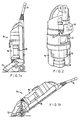
- Figure 1a is a side view of a first embodiment of a dual cyclonic vacuum cleaner incorporating the invention in a first position;
- Figure 1b is a side view of the cleaner of Figure 1a shown in an alternative position;
- Figure 2 is a perspective view of the upper portion of the cyclone assembly forming part of the cleaner shown in Figures 1a and 1b;
- Figure 3 is an enlarged sectional view through a bleed valve forming part of the invention;
- Figure 4 is a perspective view of the housing of a second embodiment of a dual cyclonic vacuum cleaner incorporating the invention;
- Figure 5 is a cross sectional view through a third embodiment; and
- Figure 6 is a schematic diagram relating to a fourth embodiment.
-
- A typical dual cyclonic vacuum cleaner is shown in Figure 1a in its non-operational position. The vacuum cleaner comprises a
main body 10 incorporating a cleaninghead 12 and ahandle 14 which can be released for use in the manner of a wand. Various tools and attachments for the wand may be provided but are not shown. The means by which thehandle 14 is released and the means by which the airflow is directed from either thehandle 14 or the cleaninghead 12 do not form part of the present invention and are described in other patents and applications. They will not be described further here. - The
main body 10 incorporates afirst cyclone 16 and asecond cyclone 18. The first cyclone is a "low efficiency" cyclone designed to remove relatively large particles from the air flowing therethrough. Thesecond cyclone 18 is designed as a "high efficiency" cyclone for removing fine dust particles from the airflow. In use, when the vacuum cleaner is in the position shown in Figure 1a, the "cylinder" mode, the dirty air inlet is formed by the nozzle in thehandle 14 which is removed and used in the manner of a wand. The airflow is directed from this dirty air inlet to the first, low efficiency cyclone, subsequently to the second, high efficiency cyclone and then expelled to atmosphere via an exit (not shown). Normally, the airflow would be directed past the motor to give a cooling effect before being expelled. When the cleaner is to be used in the "upright" mode as shown in Figure 1b, the dirty air inlet is formed by the cleaninghead 12 and the airflow is directed from there to the first cyclone and then to the clean air exit via the second cyclone. - As mentioned in the introduction, it has been found that, when a blockage occurs in the
dirty air inlet second cyclone 18 falls to an effective orifice of 13mm diameter or less, then the dust separation efficiency of the second cyclone decreases. Bleedvalves 20 are therefore positioned in the wall of the airflow passage between the exit from the first cyclone and the entry to the second cyclone. The location of thebleed valves 20 is shown in Figure 2. The airflow enters thefirst cyclone 16 via theentry port 22 and exits the first cyclone via themesh screen 24. The air passes upward to the entry port 26 to thesecond cyclone 18 and it is immediately before this entry port 26 that thebleed valves 20 are located. - Three
bleed valves 20 are located in the wall of the airflow path. Eachbleed valve 20 is shown in greatly enlarged cross-section in Figure 3. Eachvalve 20 comprises avalve body 30 to which is attached arubber washer 32 by means of afixing disk 34. The fixingdisk 34 passes through an aperture in therubber washer 32 and engages with anaperture 36 in the valve body. Alternative fixing means can, of course, be used. Acting between theairflow passage wall 38 and aflange 40 located on thevalve body 30, is an airbleed valve spring 42. Thespring 42 presses theflange 40 away from theairflow passage wall 38 so that therubber washer 32 is maintained in sealing contact with the edges of an aperture in theairflow passage wall 38. This situation prevails whilst the pressure inside the airflow passage (i.e to the right of the airflow passage wall as viewed in Figure 3) combined with the action of thespring 42 is sufficient to maintain the valve body in the position shown in Figure 3. However, if the pressure in the airflow passage falls sufficiently, then the pressure acting on the valve body outside the airflow passage becomes sufficient to open thevalve 20 by moving the valve body against the action of thespring 42 towards the right as shown in Figure 3 and thereby opening thevalve 20. Air from outside the airflow passage (ie. the atmosphere) is thus bled into the airflow passage - It has been found that the provision of three substantially
identical bleed valves 20 in theairflow passage wall 38 immediately before thesecond cyclone 18 allows a gradual bleeding of atmospheric air into the airflow passage. When the pressure in the airflow passage drops below the threshold pressure, afirst bleed valve 20 opens and the pressure in the airflow passage is thereby increased, although it will be appreciated that the increased pressure will still be less than the ambient pressure due to the suction action of the motor. If the airflow from the dirty air inlet continues to fall, then a second bleed valve will open when the combined pressure of the airflow from the dirty air inlet and the bled air from the first open valve reaches the threshold pressure of the remaining valves. Again, the combined pressure is then increased and the third valve will only be actuated when the combined pressure of the airflow from the dirty air inlet and the two open valves falls to the threshold pressure thus allowing the third valve to open. In this way, an incremental increase in the bled air is achieved. This ensures that the cleaning effect at the dirty air inlet is maintained even though air is bled into the second cyclone. Furthermore, the airflow is maintained in the second cyclone and the air passing therethrough will be efficiently separated from dust particles. The air from the second cyclone can also be passed across the motor surface to provide a cooling effect - It has been found advantageous if each of the three bleed valves has the same effective area. Ideally, the combined effective area of the three valves should be equivalent to the area of the effective orifice of the airflow at which the bleed valves are to be actuated. Thus, if the bleed valves are to be actuated at an airflow of an effective orifice of 13mm diameter, then the combined total effective area of the valves should total 132mm2. If, however, the valves are to be actuated at an airflow equivalent to an effective orifice of 14mm, then the bleed valves should have an effective combined area of 154mm2. This effective area should be equally divided between the number of bleed valves present; if three bleed valves are present then each should have an effective area of 51mm2 but if four bleed valves are present, then each should have an effective area of 38mm2. It should be noted that the effective and actual areas of each bleed valve are not the same. The actual area of the bleed valve is restricted by the presence of the valve body near the valve aperture. Thus the effective area of the bleed valve can be considerably less than the actual area of the aperture.
- It is within this scope of this invention for any number of bleed valves to be positioned in the wall of the airflow path immediately before the inlet to the second cyclone. Clearly, the greater the number of bleed valves present, the smaller, the incremental steps are in which the bled air is introduced into the airflow path. This provides for an ever increasingly gradual introduction of bled air, but also an ever increasing cost and maintenance burden. The preferred number of bleed valves is therefore three. Also, the risk of the bleed valves themselves becoming blocked by the dirt and fluff particles introduced into the vacuum cleaner via the dirty air inlet is very small because the air passing the bleed valves has already passed through the first cyclone and all of the larger particles entrained with the dirty air have been removed.
- As will be appreciated, varying amounts of bled air may be required depending upon the particular conditions in which the vacuum cleaner is being operated. For example, if the vacuum cleaner is being operated in an area where there is a small concentration of particulates to be picked up, or on a surface or in an area where partial or full sealed suction will not occur, then less bled air, or alternatively no bled air, may be required. To this end, as shown in Figs. 4, 5 and 6, the vacuum cleaner may also include means for varying the the size of the
bleed valve 76 and, accordingly, to control the volume of bled air passing into the second cyclone. - In the embodiment shown in Fig. 4,
outer cyclone casing 70 is provided with adoor 78.Door 78 is provided with ahandle 80 at one end thereof.Door 78 is movably mounted on theouter cyclone casing 70 by means of apivot 82 and is moveable between a closed position and an open position.Door 78 is sized so that when in the closed position, it completely coversbleed valve 76 and therefore prevents any bled air from entering through thebleed valve 76 into thesecond cyclone 18. - As shown in Fig. 4,
door 78 is in a partially open position. During vacuuming, the operator may manually adjust thedoor 78 from a fully closed position to a partially opened position or from a partially opened position to a fully opened position so that an increased flow of bleed air can be admitted when the vacuum cleaner is used to vacuum a large concentration of fine particulates. Alternatively, the operator may elect to leavedoor 78 in the fully open position for most vacuuming purposes. - The
bleed valve 76 may also be provided with automatic means for openingdoor 78 as the pressure insecond cyclone 18 decreases. Such a decrease in pressure could occur when a condition of full or partially sealed suction occurs. An example of such an automatic means is shown in the alternative preferred embodiment which is shown in Fig. 5. Once again, bleedvalve 76 is provided with adoor 78 which, when in the closed position, fully coversbleed valve 76 thus preventing the entry of bled air into thesecond cyclone 18 during normal vacuuming conditions. Means biasing thedoor 78 into the closed position are also provided. Accordingly, the door will move towards the open position as the pressure insecond cyclone 18 decreases thereby admitting an increased flow of bled air into the second cyclone as required. - As shown in Fig. 5,
member 86 having afirst end 88, asecond end 90 and anarm 92 extending betweenfirst end 88 andseond end 90 may be provided.First end 88 is fixedly attached to the inner surface 68 ofouter cyclone casing 70.Second end 90 is fixedly attached torear surface 84 ofdoor 78.Arm 92 may be made from any material which will biasdoor 78 into the closed position which is shown in Fig. 5. For example,arm 92 may be made from a resilient material or may incorporate spring means, such as a leaf spring. - In operation, as the pressure inside
second cyclone 18 decreases, the vacuum pressure within theair flow passage 62 will decrease to such a point that the inward force on thedoor 78 will become greater than the outward force ondoor 78 which is exerted bymember 86 thus causingdoor 78 to deflect inwards away from the dosed position and thus permitting bled air into the second cyclone. As the pressure inside the second cyclone increases (whilst remaining below the ambient pressure), at one point the vacuum pressure will increase sufficiently such that the outward force frommember 86 will become greater than the vacuum pressure thus causingdoor 78 to move to the closed position. - In a further alternative embodiment,
door 78 may be automatically controlled to allow bled air intosecond cyclone 18 in response to the amount of particulates which are exhausted from the air exit port of the second cyclone. As shown in Fig. 6, asensor 94 may be provided onair exit shaft 54.Sensor 94 senses the amount of particulates in the exhaust from the second cyclone. To this end,sensor 94 may be provided with a light source 96 (e.g. a light emitting diode) and adetector 98 which can be a photodiode. As the amount of particulates inshaft 54 increases, part of the light originating fromlight source 96 is reflected back by the particulates and picked up by thephotodiode 98. The signal fromphotodiode 98 is processed and amplified to produce anoutput signal 100 which is indicative of the amount of particulates in the exhaust from the second cyclone.Output signal 100 is transmitted todoor actuator 102.Door actuator 102 may be any suitable means which can acceptoutput signal 100 and move door 78 a predetermined amount in response to thespecific output signal 100 which is received.Door actuator 102 may be connected to a 100-volt electrical source or to any other conveniently available power supply.Shaft 104 is provided so as to connect the door actuator todoor 78. As shown in Fig. 6,shaft 104 is connected at one end todoor actuator 102, and at the other end, to therear surface 84 ofdoor 78. - In operation, as the level of particulate emissions from the second cyclone increases, the level of particulates in
shaft 54 also increases. This results in the increased reflection of light fromlight source 96 which is picked up bydetector 98 and results in aspecific output signal 100.Output signal 100 is indicative of the level of particulates in the exhaust air. This signal is transmitted todoor actuator 102 which, in response to the output signal, causesdoor 78 to move from a first position in which the door restricts the flow of bled air throughbleed valve 76 to a second position in which the door restricts the flow of bled air throughbleed valve 76 to a lesser extent thus permitting an increased flow of bled air into the second cyclone in response to the increased amount of particulates detected in the exhaust air. - If a more simplistic system is utilised, then
sensor 94 may produce only one output signal. In response to this output signal,door actuator 102 will causedoor 78 to move from the dosed postion to a fully opened position when a level of particulate emission, above a predetermined limit, is detected inshaft 54. Alternatively, in a more complex system,sensor 94 may provide an output signal which varies linearly or in a different desired relationship with the level of particulates inshaft 54. As the level of particulates inshaft 54 increases above a predetermined level, a variable output signal is produced. In response to the signal,door actuator 102 causesdoor 78 to move from the closed position to a partially open position or from a partially open position to a more fully open position in response to the level of particulates inshaft 54. Thus as an increased or decreased amount of particulate emission is detected inshaft 54,door 78 may be opened or closed a predetermined amount to adjust the actual amount of bled air entering the second cyclone. - The invention can be applied to any type of vacuum cleaner including upright, cylinder, tank, back-pack and hand-held types. The invention, although described specifically in relation to a dual cyclonic vacuum cleaner, is equally applicable to a single cyclonic vacuum cleaner or to a cyclonic vacuum cleaner having more than two cyclones as will be apparent to one skilled in the art. Where more than one cyclone is used, bleed valves can be used to maintain the airflow in any one or more of the cyclones as necessary or desired.
Claims (17)
- A vacuum cleaner comprising a dirty air inlet (12,14) communicating with a clean air outlet by means of an airflow path, a cyclone (18) being arranged in the airflow path such that, in use, dust-laden air flowing along the airflow path from the dirty air inlet (12,14) to the clean air outlet passes through the cyclone (18), characterised in that at least one bleed valve (20) is provided, downstream of the dirty air inlet (12,14) and upstream of the cyclone (18), which is adapted to introduce bled air into the airflow path to combine with the dust-laden air and to maintain the flow rate of the dust-laden air within the cyclone (18), the or each bleed valve (20) being operable when, in use, either the pressure of the air flowing along the airflow path falls to or below a predetermined level or the amount of particulates in the air at or adjacent the clean air outlet exceeds a predetermined level.
- A vacuum cleaner as claimed in Claim 1, wherein the at least one bleed valve (20) is arranged in the wall of the airflow path upstream of the cyclone (18).
- A vacuum cleaner as claimed in Claim 2, wherein two cyclones (16,18) are arranged sequentially in the airflow path, the bleed valve or valves (20) being arranged between the two cyclones (16,18).
- A vacuum cleaner as claimed in any one of Claims 1 to 3, wherein a plurality of bleed valves (20) are provided adjacent one another.
- A vacuum cleaner as claimed in Claim 4, wherein the bleed valves (20) are substantially identical to one another.
- A vacuum cleaner as claimed in Claim 4 or 5, wherein three bleed valves (20) are provided adjacent one another.
- A vacuum cleaner as claimed in any one of the preceding claims, wherein the or each bleed valve (20) is spring loaded.
- A vacuum cleaner as claimed in any one of the preceding claims, wherein the effective area of the bleed valve (20), or the total effective area of the bleed valves (20), is between 120mm2 and 150mm2.
- A vacuum cleaner as claimed in Claim 8, wherein the effective area of the bleed valve (20), or the total effective area of the bleed valves (20), is substantially 132mm2.
- A vacuum cleaner as claimed in any one of the preceding claims, wherein the or each bleed valve (20) comprises a door (78) movable between a first position in which, in use, the flow of bled air through the bleed valve (20) is restricted and a second position in which, in use, the flow of bled air through the bleed valve (20) is restricted to a lesser extent than when the door (78) is in the first position.
- A vacuum cleaner as claimed in Claim 10, wherein the position of the door (78) is controlled by means responsive to the pressure of the air flow in the cyclone (18).
- A vacuum cleaner as claimed in Claim 10, wherein the position of the door (78) is controlled by means (94) responsive to the concentration of particulates in the air exhausted from the cyclone (18).
- A vacuum cleaner as claimed in any one of the preceding claims, wherein the or each bleed valve (20) is designed to open when the pressure in the airflow path is that produced by an airflow equivalent to an effective orifice of between 10mm and 15mm diameter, or less.
- A vacuum cleaner as claimed in Claim 13, wherein the or each bleed valve (20) is designed to open when the pressure in the airflow path is that produced by an airflow equivalent to an effective orifice of 13mm diameter, or less.
- A vacuum cleaner as claimed in any one of Claims 1 to 12, wherein the amount of particulates in the air at or adjacent the clean air outlet is determined by means of a sensor (94) provided downstream of the cyclone (18).
- A vacuum cleaner as claimed in Claim 15, wherein the sensor (94) is provided with a light source (96) and a detector (98).
- A method of operating a cyclonic vacuum cleaner having first and second cyclones (16,18) arranged in series, comprising the steps of:-characterised in that, bled air is introduced to and combined with the partially filtered air before the entry thereof into the second cyclone (18) in order to maintain the rate of the airflow within the second cyclone (18) and for reducing particulates in the further cleaned air.a) admitting dirty air into the first cyclone (16);b) partially cleaning the dirty air in the first cyclone (16) to produce partially filtered air;c) conducting the partially filtered air from the first cyclone (16) to the second cyclone (18);d) further cleaning the partially filtered air in the second cyclone (18) to produce further cleaned air; ande) exhausting the further cleaned air from the second cyclone (18),
Applications Claiming Priority (5)
| Application Number | Priority Date | Filing Date | Title |
|---|---|---|---|
| US97544692A | 1992-06-24 | 1992-06-24 | |
| US975446 | 1992-06-24 | ||
| GB929225599A GB9225599D0 (en) | 1992-12-08 | 1992-12-08 | Vacuum cleaner |
| GB9225599 | 1992-12-08 | ||
| PCT/GB1993/001325 WO1994000046A1 (en) | 1992-06-24 | 1993-06-24 | Dual cyclonic vacuum cleaner |
Publications (3)
| Publication Number | Publication Date |
|---|---|
| EP0647114A1 EP0647114A1 (en) | 1995-04-12 |
| EP0647114B1 EP0647114B1 (en) | 1997-03-26 |
| EP0647114B2 true EP0647114B2 (en) | 2001-11-14 |
Family
ID=26302121
Family Applications (1)
| Application Number | Title | Priority Date | Filing Date |
|---|---|---|---|
| EP93913422A Expired - Lifetime EP0647114B2 (en) | 1992-06-24 | 1993-06-24 | Cyclonic vacuum cleaner |
Country Status (10)
| Country | Link |
|---|---|
| EP (1) | EP0647114B2 (en) |
| JP (1) | JP3207201B2 (en) |
| AT (1) | ATE150630T1 (en) |
| AU (1) | AU669539B2 (en) |
| CA (1) | CA2138985C (en) |
| DE (1) | DE69309275T3 (en) |
| ES (1) | ES2099450T3 (en) |
| HK (1) | HK1000865A1 (en) |
| SG (1) | SG46302A1 (en) |
| WO (1) | WO1994000046A1 (en) |
Cited By (2)
| Publication number | Priority date | Publication date | Assignee | Title |
|---|---|---|---|---|
| US7845046B2 (en) | 2003-10-15 | 2010-12-07 | Black & Decker, Inc. | Hand-held cordless vacuum cleaner |
| US8032984B2 (en) | 2006-01-27 | 2011-10-11 | Black & Decker Inc. | Vacuum cleaner filter cleaning mechanisms |
Families Citing this family (56)
| Publication number | Priority date | Publication date | Assignee | Title |
|---|---|---|---|---|
| GB2315231A (en) * | 1996-07-15 | 1998-01-28 | Notetry Ltd | Apparatus for Separating Particles |
| GB2320419B (en) | 1996-12-20 | 2000-08-16 | Notetry Ltd | Improved vacuum cleaner |
| GB9815783D0 (en) * | 1998-07-20 | 1998-09-16 | Notetry Ltd | Apparatus for separating dirt or dust from an airflow |
| GB2344750B (en) | 1998-12-18 | 2002-06-26 | Notetry Ltd | Vacuum cleaner |
| GB9902000D0 (en) * | 1999-01-30 | 1999-03-17 | Delta Biotechnology Ltd | Process |
| US6221134B1 (en) | 1999-07-27 | 2001-04-24 | G.B.D. Corp. | Apparatus and method for separating particles from a cyclonic fluid flow |
| US6251296B1 (en) | 1999-07-27 | 2001-06-26 | G.B.D. Corp. | Apparatus and method for separating particles from a cyclonic fluid flow |
| US6440197B1 (en) | 1999-07-27 | 2002-08-27 | G.B.D. Corp. | Apparatus and method separating particles from a cyclonic fluid flow including an apertured particle separation member within a cyclonic flow region |
| US6228260B1 (en) | 1999-07-27 | 2001-05-08 | G. B. D. Corp. | Apparatus for separating particles from a cyclonic fluid flow |
| US6231645B1 (en) | 1999-07-27 | 2001-05-15 | G.B.D. Corp. | Apparatus and method for separating particles from a cyclonic fluid flow utilizing a movable access member associated with a cyclonic separator |
| US6228151B1 (en) | 1999-08-18 | 2001-05-08 | G.B.D. Corp. | Apparatus and method for separating particles from a cyclonic fluid flow |
| US6341404B1 (en) * | 2000-01-13 | 2002-01-29 | Royal Appliance Mfg. Co. | Upright vacuum cleaner with cyclonic airflow pathway |
| GB0104675D0 (en) | 2001-02-24 | 2001-04-11 | Dyson Ltd | A tool for a vacuum cleaner |
| GB2372431B (en) * | 2001-02-24 | 2004-09-15 | Dyson Ltd | A domestic appliance |
| DE102005047812A1 (en) * | 2005-10-05 | 2007-04-12 | Miele & Cie. Kg | Method for treatment of dust in which dust is separated in vacuum cleaner into at least two fractions which differ by size and/or mass of dust particles, and in which dust binding agent is fed to one fraction |
| ATE517571T1 (en) | 2005-08-26 | 2011-08-15 | Miele & Cie | METHOD FOR TREATING DUST AND DEVICES FOR PERFORMING SUCH METHOD |
| DE102005041170B3 (en) * | 2005-08-26 | 2007-01-18 | Miele & Cie. Kg | Dust separating container for e.g. floor vacuum cleaner, has air inlet, air outlet, and separating plate whose arrangement produces sudden deflection of airflow, where dust particles with minimum size are separated from airflow |
| DE102006046328B4 (en) * | 2006-09-28 | 2008-06-19 | Miele & Cie. Kg | Device for separating dust from dust-laden air, in particular for use in a vacuum cleaner |
| DE102008004393B3 (en) * | 2008-01-14 | 2009-07-16 | Miele & Cie. Kg | Device for separating dust from dust-laden air, in particular for use in a vacuum cleaner |
| US9211044B2 (en) | 2011-03-04 | 2015-12-15 | Omachron Intellectual Property Inc. | Compact surface cleaning apparatus |
| GB2502131B (en) * | 2012-05-17 | 2014-11-05 | Dyson Technology Ltd | Autonomous vacuum cleaner |
| DE102012105142B4 (en) * | 2012-06-14 | 2020-03-05 | Miele & Cie. Kg | Power controller for a vacuum cleaner and vacuum cleaner with such a power controller |
| US9227201B2 (en) | 2013-02-28 | 2016-01-05 | Omachron Intellectual Property Inc. | Cyclone such as for use in a surface cleaning apparatus |
| US9451855B2 (en) | 2013-02-28 | 2016-09-27 | Omachron Intellectual Property Inc. | Surface cleaning apparatus |
| US9295995B2 (en) | 2013-02-28 | 2016-03-29 | Omachron Intellectual Property Inc. | Cyclone such as for use in a surface cleaning apparatus |
| US9238235B2 (en) | 2013-02-28 | 2016-01-19 | Omachron Intellectual Property Inc. | Cyclone such as for use in a surface cleaning apparatus |
| US9227151B2 (en) | 2013-02-28 | 2016-01-05 | Omachron Intellectual Property Inc. | Cyclone such as for use in a surface cleaning apparatus |
| US9456721B2 (en) | 2013-02-28 | 2016-10-04 | Omachron Intellectual Property Inc. | Surface cleaning apparatus |
| US9820621B2 (en) | 2013-02-28 | 2017-11-21 | Omachron Intellectual Property Inc. | Surface cleaning apparatus |
| US9326652B2 (en) | 2013-02-28 | 2016-05-03 | Omachron Intellectual Property Inc. | Surface cleaning apparatus |
| US20140237764A1 (en) | 2013-02-28 | 2014-08-28 | G.B.D. Corp. | Cyclone such as for use in a surface cleaning apparatus |
| KR20160023120A (en) * | 2014-08-21 | 2016-03-03 | 삼성전자주식회사 | Robot cleaner |
| GB2531043A (en) | 2014-10-08 | 2016-04-13 | Dyson Technology Ltd | Vacuum cleaner |
| US10022027B2 (en) | 2014-12-17 | 2018-07-17 | Omachron Intellectual Property Inc. | All in the head surface cleaning apparatus |
| US9883781B2 (en) | 2014-12-17 | 2018-02-06 | Omachron Intellectual Property Inc. | All in the head surface cleaning apparatus |
| US10258210B2 (en) | 2016-12-27 | 2019-04-16 | Omachron Intellectual Property Inc. | Multistage cyclone and surface cleaning apparatus having same |
| US10292550B2 (en) | 2016-08-29 | 2019-05-21 | Omachron Intellectual Property Inc. | Surface cleaning apparatus |
| US10433689B2 (en) | 2016-08-29 | 2019-10-08 | Omachron Intellectual Property Inc. | Surface cleaning apparatus |
| US10136780B2 (en) | 2016-08-29 | 2018-11-27 | Omachron Intellectual Property Inc. | Surface cleaning apparatus |
| US10441124B2 (en) | 2016-08-29 | 2019-10-15 | Omachron Intellectual Property Inc. | Surface cleaning apparatus |
| US10405711B2 (en) | 2016-08-29 | 2019-09-10 | Omachron Intellectual Property Inc. | Surface cleaning apparatus |
| US10729295B2 (en) | 2016-08-29 | 2020-08-04 | Omachron Intellectual Property Inc. | Surface cleaning apparatus |
| US10321794B2 (en) | 2016-08-29 | 2019-06-18 | Omachron Intellectual Property Inc. | Surface cleaning apparatus |
| US10136779B2 (en) | 2016-08-29 | 2018-11-27 | Omachron Intellectual Property Inc. | Surface cleaning apparatus |
| US10413141B2 (en) | 2016-08-29 | 2019-09-17 | Omachron Intellectual Property Inc. | Surface cleaning apparatus |
| US10441125B2 (en) | 2016-08-29 | 2019-10-15 | Omachron Intellectual Property Inc. | Surface cleaning apparatus |
| US9962050B2 (en) | 2016-08-29 | 2018-05-08 | Omachron Intellectual Property Inc. | Surface cleaning apparatus |
| US10405709B2 (en) | 2016-12-27 | 2019-09-10 | Omachron Intellectual Property Inc. | Multistage cyclone and surface cleaning apparatus having same |
| US10016106B1 (en) | 2016-12-27 | 2018-07-10 | Omachron Intellectual Property Inc. | Multistage cyclone and surface cleaning apparatus having same |
| US10299643B2 (en) | 2016-12-27 | 2019-05-28 | Omachron Intellectual Property Inc. | Multistage cyclone and surface cleaning apparatus having same |
| US10827891B2 (en) | 2016-12-27 | 2020-11-10 | Omachron Intellectual Property Inc. | Multistage cyclone and surface cleaning apparatus having same |
| US10271704B2 (en) | 2016-12-27 | 2019-04-30 | Omachron Intellectual Property Inc. | Multistage cyclone and surface cleaning apparatus having same |
| US11285495B2 (en) | 2016-12-27 | 2022-03-29 | Omachron Intellectual Property Inc. | Multistage cyclone and surface cleaning apparatus having same |
| JP6443462B2 (en) * | 2017-01-12 | 2018-12-26 | 三菱電機株式会社 | Cyclone separation device and vacuum cleaner |
| US11751740B2 (en) | 2019-11-18 | 2023-09-12 | Omachron Intellectual Property Inc. | Multi-inlet cyclone |
| US11246462B2 (en) | 2019-11-18 | 2022-02-15 | Omachron Intellectual Property Inc. | Multi-inlet cyclone |
Citations (1)
| Publication number | Priority date | Publication date | Assignee | Title |
|---|---|---|---|---|
| DE1407995A1 (en) † | 1964-10-23 | 1969-02-20 | Siemens Elektrogeraete Gmbh | Device for separating solid components from an air flow |
Family Cites Families (3)
| Publication number | Priority date | Publication date | Assignee | Title |
|---|---|---|---|---|
| EP0042723B1 (en) * | 1980-06-19 | 1985-08-21 | Rotork Appliances Limited | Vacuum cleaning appliance |
| GR82013B (en) * | 1983-07-08 | 1984-12-12 | Notetry Ltd | |
| US5078761A (en) * | 1990-07-06 | 1992-01-07 | Notetry Limited | Shroud |
-
1993
- 1993-06-24 DE DE69309275T patent/DE69309275T3/en not_active Expired - Lifetime
- 1993-06-24 EP EP93913422A patent/EP0647114B2/en not_active Expired - Lifetime
- 1993-06-24 JP JP50215994A patent/JP3207201B2/en not_active Expired - Lifetime
- 1993-06-24 SG SG1996002398A patent/SG46302A1/en unknown
- 1993-06-24 ES ES93913422T patent/ES2099450T3/en not_active Expired - Lifetime
- 1993-06-24 AU AU43502/93A patent/AU669539B2/en not_active Ceased
- 1993-06-24 AT AT93913422T patent/ATE150630T1/en not_active IP Right Cessation
- 1993-06-24 WO PCT/GB1993/001325 patent/WO1994000046A1/en active IP Right Grant
- 1993-06-24 CA CA002138985A patent/CA2138985C/en not_active Expired - Fee Related
-
1997
- 1997-12-16 HK HK97102451A patent/HK1000865A1/en not_active IP Right Cessation
Patent Citations (1)
| Publication number | Priority date | Publication date | Assignee | Title |
|---|---|---|---|---|
| DE1407995A1 (en) † | 1964-10-23 | 1969-02-20 | Siemens Elektrogeraete Gmbh | Device for separating solid components from an air flow |
Cited By (2)
| Publication number | Priority date | Publication date | Assignee | Title |
|---|---|---|---|---|
| US7845046B2 (en) | 2003-10-15 | 2010-12-07 | Black & Decker, Inc. | Hand-held cordless vacuum cleaner |
| US8032984B2 (en) | 2006-01-27 | 2011-10-11 | Black & Decker Inc. | Vacuum cleaner filter cleaning mechanisms |
Also Published As
| Publication number | Publication date |
|---|---|
| ES2099450T3 (en) | 1997-05-16 |
| SG46302A1 (en) | 1998-02-20 |
| EP0647114B1 (en) | 1997-03-26 |
| AU669539B2 (en) | 1996-06-13 |
| CA2138985C (en) | 2004-01-20 |
| AU4350293A (en) | 1994-01-24 |
| HK1000865A1 (en) | 1998-05-01 |
| ATE150630T1 (en) | 1997-04-15 |
| JPH08501226A (en) | 1996-02-13 |
| CA2138985A1 (en) | 1994-01-06 |
| JP3207201B2 (en) | 2001-09-10 |
| WO1994000046A1 (en) | 1994-01-06 |
| DE69309275D1 (en) | 1997-04-30 |
| DE69309275T2 (en) | 1997-09-04 |
| DE69309275T3 (en) | 2002-06-27 |
| EP0647114A1 (en) | 1995-04-12 |
Similar Documents
| Publication | Publication Date | Title |
|---|---|---|
| EP0647114B2 (en) | Cyclonic vacuum cleaner | |
| US5558697A (en) | Dual cyclonic vacuum cleaner | |
| US5141309A (en) | Apparatus for indicating how dirty an air filter is in a vacuum-cleaning apparatus, in a room filter, etc. | |
| EP1361812B1 (en) | A vacuum cleaner | |
| US7931716B2 (en) | Handheld cleaning appliance | |
| US7861368B2 (en) | Vacuum cleaning head | |
| US4294595A (en) | Vacuum cleaner including automatic shutoff device | |
| KR100597548B1 (en) | Vacuum cleaner | |
| US20180078103A1 (en) | Vacuum cleaner with height adjustment of suction nozzle | |
| US7462210B2 (en) | Dust collecting unit for vacuum cleaner | |
| US4940474A (en) | Suction cleaner | |
| GB2372431A (en) | Air bleed valve arrangement in a vacuum cleaner | |
| US4063326A (en) | Vacuum cleaner suction control | |
| EP1267695B1 (en) | Improvements in or relating to electric appliances | |
| US4463473A (en) | Vacuum cleaner | |
| US20040143929A1 (en) | Vacuum Cleaner | |
| JP2719822B2 (en) | Electric vacuum cleaner | |
| US20230414049A1 (en) | Vacuum cleaner nozzle | |
| JPH04327823A (en) | Vacuum cleaner | |
| GB2360935A (en) | Vacuum cleaner having a secondary inlet for drawing in airborne particles |
Legal Events
| Date | Code | Title | Description |
|---|---|---|---|
| PUAI | Public reference made under article 153(3) epc to a published international application that has entered the european phase |
Free format text: ORIGINAL CODE: 0009012 |
|
| 17P | Request for examination filed |
Effective date: 19941230 |
|
| AK | Designated contracting states |
Kind code of ref document: A1 Designated state(s): AT BE CH DE DK ES FR GB GR IE IT LI LU MC NL PT SE |
|
| GRAG | Despatch of communication of intention to grant |
Free format text: ORIGINAL CODE: EPIDOS AGRA |
|
| 17Q | First examination report despatched |
Effective date: 19960708 |
|
| GRAH | Despatch of communication of intention to grant a patent |
Free format text: ORIGINAL CODE: EPIDOS IGRA |
|
| GRAH | Despatch of communication of intention to grant a patent |
Free format text: ORIGINAL CODE: EPIDOS IGRA |
|
| GRAA | (expected) grant |
Free format text: ORIGINAL CODE: 0009210 |
|
| RAP1 | Party data changed (applicant data changed or rights of an application transferred) |
Owner name: NOTETRY LIMITED |
|
| AK | Designated contracting states |
Kind code of ref document: B1 Designated state(s): AT BE CH DE DK ES FR GB GR IE IT LI LU MC NL PT SE |
|
| PG25 | Lapsed in a contracting state [announced via postgrant information from national office to epo] |
Ref country code: LI Free format text: LAPSE BECAUSE OF FAILURE TO SUBMIT A TRANSLATION OF THE DESCRIPTION OR TO PAY THE FEE WITHIN THE PRESCRIBED TIME-LIMIT Effective date: 19970326 Ref country code: GR Free format text: LAPSE BECAUSE OF FAILURE TO SUBMIT A TRANSLATION OF THE DESCRIPTION OR TO PAY THE FEE WITHIN THE PRESCRIBED TIME-LIMIT Effective date: 19970326 Ref country code: DK Effective date: 19970326 Ref country code: CH Free format text: LAPSE BECAUSE OF FAILURE TO SUBMIT A TRANSLATION OF THE DESCRIPTION OR TO PAY THE FEE WITHIN THE PRESCRIBED TIME-LIMIT Effective date: 19970326 Ref country code: AT Effective date: 19970326 |
|
| REF | Corresponds to: |
Ref document number: 150630 Country of ref document: AT Date of ref document: 19970415 Kind code of ref document: T |
|
| REG | Reference to a national code |
Ref country code: CH Ref legal event code: EP |
|
| ITF | It: translation for a ep patent filed |
Owner name: 0508;73TOFBUZZI, NOTARO&ANTONIELLI D'OUL |
|
| REF | Corresponds to: |
Ref document number: 69309275 Country of ref document: DE Date of ref document: 19970430 |
|
| ET | Fr: translation filed | ||
| REG | Reference to a national code |
Ref country code: ES Ref legal event code: FG2A Ref document number: 2099450 Country of ref document: ES Kind code of ref document: T3 |
|
| REG | Reference to a national code |
Ref country code: IE Ref legal event code: FG4D Free format text: 72898 |
|
| REG | Reference to a national code |
Ref country code: CH Ref legal event code: NV Representative=s name: PATENTANWAELTE SCHAAD, BALASS, MENZL & PARTNER AG |
|
| PG25 | Lapsed in a contracting state [announced via postgrant information from national office to epo] |
Ref country code: LU Free format text: LAPSE BECAUSE OF NON-PAYMENT OF DUE FEES Effective date: 19970624 |
|
| PG25 | Lapsed in a contracting state [announced via postgrant information from national office to epo] |
Ref country code: PT Effective date: 19970626 |
|
| PLBQ | Unpublished change to opponent data |
Free format text: ORIGINAL CODE: EPIDOS OPPO |
|
| PLBI | Opposition filed |
Free format text: ORIGINAL CODE: 0009260 |
|
| 26 | Opposition filed |
Opponent name: HOOVER LIMITED Effective date: 19971021 |
|
| PG25 | Lapsed in a contracting state [announced via postgrant information from national office to epo] |
Ref country code: MC Effective date: 19971231 |
|
| PLBF | Reply of patent proprietor to notice(s) of opposition |
Free format text: ORIGINAL CODE: EPIDOS OBSO |
|
| NLR1 | Nl: opposition has been filed with the epo |
Opponent name: HOOVER LIMITED |
|
| PLBF | Reply of patent proprietor to notice(s) of opposition |
Free format text: ORIGINAL CODE: EPIDOS OBSO |
|
| PLAW | Interlocutory decision in opposition |
Free format text: ORIGINAL CODE: EPIDOS IDOP |
|
| APAC | Appeal dossier modified |
Free format text: ORIGINAL CODE: EPIDOS NOAPO |
|
| APAE | Appeal reference modified |
Free format text: ORIGINAL CODE: EPIDOS REFNO |
|
| APAC | Appeal dossier modified |
Free format text: ORIGINAL CODE: EPIDOS NOAPO |
|
| APAC | Appeal dossier modified |
Free format text: ORIGINAL CODE: EPIDOS NOAPO |
|
| PLAW | Interlocutory decision in opposition |
Free format text: ORIGINAL CODE: EPIDOS IDOP |
|
| PGFP | Annual fee paid to national office [announced via postgrant information from national office to epo] |
Ref country code: IE Payment date: 20010622 Year of fee payment: 9 |
|
| PGFP | Annual fee paid to national office [announced via postgrant information from national office to epo] |
Ref country code: CH Payment date: 20010628 Year of fee payment: 9 |
|
| PGFP | Annual fee paid to national office [announced via postgrant information from national office to epo] |
Ref country code: ES Payment date: 20010629 Year of fee payment: 9 |
|
| PGFP | Annual fee paid to national office [announced via postgrant information from national office to epo] |
Ref country code: BE Payment date: 20010817 Year of fee payment: 9 |
|
| PUAH | Patent maintained in amended form |
Free format text: ORIGINAL CODE: 0009272 |
|
| STAA | Information on the status of an ep patent application or granted ep patent |
Free format text: STATUS: PATENT MAINTAINED AS AMENDED |
|
| 27A | Patent maintained in amended form |
Effective date: 20011114 |
|
| AK | Designated contracting states |
Kind code of ref document: B2 Designated state(s): AT BE CH DE DK ES FR GB GR IE IT LI LU MC NL PT SE |
|
| REG | Reference to a national code |
Ref country code: CH Ref legal event code: AEN Free format text: MAINTIEN DU BREVET DONT L'ETENDUE A ETE MODIFIEE |
|
| REG | Reference to a national code |
Ref country code: GB Ref legal event code: IF02 |
|
| NLR2 | Nl: decision of opposition | ||
| PG25 | Lapsed in a contracting state [announced via postgrant information from national office to epo] |
Ref country code: ES Free format text: LAPSE BECAUSE OF FAILURE TO SUBMIT A TRANSLATION OF THE DESCRIPTION OR TO PAY THE FEE WITHIN THE PRESCRIBED TIME-LIMIT Effective date: 20020225 |
|
| NLR3 | Nl: receipt of modified translations in the netherlands language after an opposition procedure | ||
| ET3 | Fr: translation filed ** decision concerning opposition | ||
| REG | Reference to a national code |
Ref country code: CH Ref legal event code: PL |
|
| PG25 | Lapsed in a contracting state [announced via postgrant information from national office to epo] |
Ref country code: IE Free format text: LAPSE BECAUSE OF NON-PAYMENT OF DUE FEES Effective date: 20020624 |
|
| PG25 | Lapsed in a contracting state [announced via postgrant information from national office to epo] |
Ref country code: BE Free format text: LAPSE BECAUSE OF NON-PAYMENT OF DUE FEES Effective date: 20020630 |
|
| REG | Reference to a national code |
Ref country code: IE Ref legal event code: MM4A |
|
| NLT1 | Nl: modifications of names registered in virtue of documents presented to the patent office pursuant to art. 16 a, paragraph 1 |
Owner name: DYSON TECHNOLOGY LIMITED |
|
| PG25 | Lapsed in a contracting state [announced via postgrant information from national office to epo] |
Ref country code: IT Free format text: LAPSE BECAUSE OF NON-PAYMENT OF DUE FEES;WARNING: LAPSES OF ITALIAN PATENTS WITH EFFECTIVE DATE BEFORE 2007 MAY HAVE OCCURRED AT ANY TIME BEFORE 2007. THE CORRECT EFFECTIVE DATE MAY BE DIFFERENT FROM THE ONE RECORDED. Effective date: 20050624 |
|
| REG | Reference to a national code |
Ref country code: FR Ref legal event code: CD Ref country code: FR Ref legal event code: CA |
|
| APAH | Appeal reference modified |
Free format text: ORIGINAL CODE: EPIDOSCREFNO |
|
| PGFP | Annual fee paid to national office [announced via postgrant information from national office to epo] |
Ref country code: SE Payment date: 20070607 Year of fee payment: 15 |
|
| EUG | Se: european patent has lapsed | ||
| PG25 | Lapsed in a contracting state [announced via postgrant information from national office to epo] |
Ref country code: SE Free format text: LAPSE BECAUSE OF NON-PAYMENT OF DUE FEES Effective date: 20080625 |
|
| PGFP | Annual fee paid to national office [announced via postgrant information from national office to epo] |
Ref country code: NL Payment date: 20100624 Year of fee payment: 18 |
|
| REG | Reference to a national code |
Ref country code: NL Ref legal event code: V1 Effective date: 20120101 |
|
| PG25 | Lapsed in a contracting state [announced via postgrant information from national office to epo] |
Ref country code: NL Free format text: LAPSE BECAUSE OF NON-PAYMENT OF DUE FEES Effective date: 20120101 |
|
| PGFP | Annual fee paid to national office [announced via postgrant information from national office to epo] |
Ref country code: DE Payment date: 20120627 Year of fee payment: 20 |
|
| PGFP | Annual fee paid to national office [announced via postgrant information from national office to epo] |
Ref country code: FR Payment date: 20120705 Year of fee payment: 20 Ref country code: GB Payment date: 20120625 Year of fee payment: 20 |
|
| REG | Reference to a national code |
Ref country code: DE Ref legal event code: R071 Ref document number: 69309275 Country of ref document: DE |
|
| REG | Reference to a national code |
Ref country code: GB Ref legal event code: PE20 Expiry date: 20130623 |
|
| PG25 | Lapsed in a contracting state [announced via postgrant information from national office to epo] |
Ref country code: DE Free format text: LAPSE BECAUSE OF EXPIRATION OF PROTECTION Effective date: 20130625 Ref country code: GB Free format text: LAPSE BECAUSE OF EXPIRATION OF PROTECTION Effective date: 20130623 |