EP0646854A2 - High frequency clock signal distribution circuit with reduced clock skew - Google Patents
High frequency clock signal distribution circuit with reduced clock skew Download PDFInfo
- Publication number
- EP0646854A2 EP0646854A2 EP94115062A EP94115062A EP0646854A2 EP 0646854 A2 EP0646854 A2 EP 0646854A2 EP 94115062 A EP94115062 A EP 94115062A EP 94115062 A EP94115062 A EP 94115062A EP 0646854 A2 EP0646854 A2 EP 0646854A2
- Authority
- EP
- European Patent Office
- Prior art keywords
- clock signal
- distribution circuit
- buffers
- stage
- inverter
- Prior art date
- Legal status (The legal status is an assumption and is not a legal conclusion. Google has not performed a legal analysis and makes no representation as to the accuracy of the status listed.)
- Granted
Links
Images


Classifications
-
- G—PHYSICS
- G06—COMPUTING; CALCULATING OR COUNTING
- G06F—ELECTRIC DIGITAL DATA PROCESSING
- G06F1/00—Details not covered by groups G06F3/00 - G06F13/00 and G06F21/00
- G06F1/04—Generating or distributing clock signals or signals derived directly therefrom
- G06F1/10—Distribution of clock signals, e.g. skew
Definitions
- This invention relates to a clock signal distribution circuit that can distribute a high frequency clock signal to a plurality of registers.
- the first example is a tree structure driving method represented by an H-Tree structure (for example, as disclosed in "IEEE 1992 CUSTOM INTEGRATED CIRCUITS CONFERENCE", 28.3.1 - 28.3.4) in which it is possible to achieve a reduced clock skew by equalization of loads and an increased driving capability by a hierarchal arrangement of buffers.
- H-Tree structure for example, as disclosed in "IEEE 1992 CUSTOM INTEGRATED CIRCUITS CONFERENCE", 28.3.1 - 28.3.4
- the second example is a large driver packaged driving method (for example, as disclosed in "IEEE 1992 INTERNATIONAL SOLID STATE CIRCUITS CONFERENCE", TA 6.2, pp. 106 - 107) in which it is possible to achieve the reduced skew by reducing a wire delay time by means of a low resistance clock trunk line design, and to increase a driving capability by means of a large driver.
- An inverter having a simple structure and a large driving capability is utilized as a buffer of the tree structure driving method. To attain a large driving capability, the size of an inverter is increased, and the number of branches in the tree structure is reduced.
- a hierarchical structure made up of a number of inverters is utilized as a driver of the large driver packaged driving method.
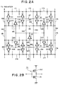
- Fig. 1 shows such conventional clock signal distribution circuit wherein the buffers of the final stage are mutually connected or short-circuited with each other.
- this circuit is formed by a buffer 401 of a first stage, buffers 402 - 405 of a second stage, and buffers 411 - 414, 421 - 424, 431 - 434 and 441 - 444 of a third stage, and output terminals of all the third stage buffers 411 - 444 are short-circuited by a plurality of short-circuit wirings 471 - 494.
- the primary object of the present invention is to provide a high frequency clock signal distribution circuit in which clock skew is efficiently reduced.
- Another object of the present invention is to provide a high frequency clock signal distribution circuit having a large driving capability.
- a clock signal distribution circuit of a tree structure comprising: a plurality of buffers arranged in a plurality of hierarchal stages; and short-circuit wirings for short-circuiting output terminals of the buffers at each stage of the plurality of hierarchal stages.
- output terminals on the same hierarchical level are mutually short-circuited on several levels at each buffer stage, or at intervals of several buffer stages, constituting the tree structure on several levels. It is possible to reduce a phase difference (skew) between two signals by short-circuiting the two signals. The smaller the original skew is, the larger this reducing effect is. Skew caused at each stage or at several stages is sufficiently small, and hence the skew thus caused can be effectively reduced every time short-circuiting occurs.
- a clock signal distribution circuit of a tree structure having a plurality of buffers arranged in a plurality of hierarchal stages, each of the plurality of buffers comprising: an input stage inverter; and an output stage inverter connected in series to said input stage inverter, the output stage inverter being formed by a transistor larger in size than that of the input stage inverter so that each of the plurality of buffers has a low output on-resistance and a small input capacitance.
- an inverter having a multi-stage configuration is used as a buffer constituting the tree structure.
- an inverter at a top or input stage is made small and an inverter at the final or output stage is made large so that an input capacitance and an output on-resistance of the buffer may become small.
- the absolute delay of the clock distribution circuit increases.
- matching of phases of a clock signal inputted into each register is especially important in the distribution of a clock signal, and hence an increase in the absolute delay of the clock distribution circuit does not matter.
- Fig. 2A is a block diagram showing a clock signal distribution circuit according to a first embodiment of the present invention.
- the circuit comprises a buffer 101 of a first stage, four buffers 102 - 105 of a second stage, and sixteen buffers grouped into four groups 111 - 114, 121 - 124, 131 - 134 and 141 - 144 of a third stage, thereby forming the H-Tree structure.
- Each buffer in this embodiment is constituted by a single inverter.
- the single inverter 111 can be formed by a pair of opposite mode MOS field effect transistors, i.e., a P-channel MOSFET 152 and an N-channel MOSFET 151 connected in series between a power source and ground as shown in Fig. 2B.
- Output terminals of the second stage buffers 102, 103, 104 and 105 are short-circuited by short-circuit wirings 161, 162, 163 and 164.
- the third stage buffers 111 - 114, 121 - 124, 131 - 134 and 141 - 144 are short-circuited by short-circuit wirings 171 - 194.
- Fig. 3A is a block diagram showing a clock signal distribution circuit according to a second embodiment of the present invention.
- the circuit comprises a buffer 201 of a first stage, four buffers 202 - 205 of a second stage, and sixteen buffers 211 - 214, 221 - 224, 231 - 234 and 241 - 244 of a third stage.
- each of the above buffers constituting the H-Tree structure is formed by two-stage inverters.
- the buffer 211 taken as an example, is formed by an inverter 251 at an input stage and an inverter 252 at an output stage as shown in Fig. 3B.
- the size of the output stage inverter 252 is set “n” times as large as that of the input stage inverter 251. If MOS transistors are used as an inverter, the channel width of each MOS transistor at the output stage is set “n” times as large as that of each MOS transistor at the input stage. In comparison with a buffer configuration made of a single inverter which is "n" times as large as that of the inverter at the input stage of the two-stage inverter, an input capacitance of a buffer on the subsequent stage can be reduced to 1/n that of a buffer on the previous stage. Thus, this clock signal distribution circuit is effective in sharpening a clock signal even when wire resistance becomes large as a result of microminiaturization and the extension of the length of a clock signal line.
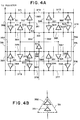
- Fig. 4A is a block diagram showing a clock signal distribution circuit according to a third embodiment of the present invention.
- each of buffers 301 of the first stage, 302 - 305 of the second stage, and 311 - 314, 321 - 324, 331 - 334 and 341 - 344 of the third stage, constituting as a whole the H-Tree structure is made up of a two-stage inverter.
- the buffer 311, taken as an example, is formed by an input stage inverter 351 and an output stage inverter 352 as shown in Fig. 4B.
- output terminals of the second stage buffers 302 - 305 are short-circuited by short-circuit wirings 361 - 364 and output terminals of the third stage buffers 311 - 314, 321 - 324, 331 - 334 and 341 - 344 are short-circuited by short-circuit wirings 371 - 394, respectively.
- the size of the output stage inverter is set "n" times as large as that of the input stage inverter.
- an input capacitance of a buffer at the subsequent stage can be reduced to 1/n that of a buffer at the previous stage when compared with the buffer structure made of a single inverter which is "n" times as large as that of the inverter at the input stage in the two-stage inverter.
- this clock signal distribution circuit is effective in sharpening a clock signal even when wire resistance becomes large as a result of microminiaturization and the extension of the length of a clock signal line.
- a clock distribution load is equalized by the H-Tree structure, and the output terminals of the buffers are short-circuited at each stage. Hence, the skew caused at each stage is small, and it is possible to efficiently reduce the generated skew by short-circuiting.
- the buffer when the buffer is made up of inverters arranged in several stages, it may be considered that the level of the tree structure becomes deep, and hence the amount of skew caused by process variations becomes large.
- the reduction of skew by short-circuiting at each buffer stage is effective even in this situation.
- the sharpening of a clock signal and the reduction of skew allow the distribution of a high frequency clock signal.
- a difference in effects between a clock signal distribution circuit of the present invention and a conventional clock signal distribution circuit will be described in detail hereunder.
- a clock skew reducing effect is first estimated using the clock signal distribution circuit of the present invention (shown in Fig. 4) and the conventional clock signal distribution circuit (shown in Fig. 1).
- the clock skew caused per one buffer stage is "t"
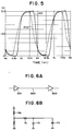
- Reference numeral 501 designates a clock signal waveform obtained by the clock signal distribution circuit of the invention shown in Fig. 4
- reference numeral 502 designates a clock signal waveform obtained by the conventional clock signal distribution circuit shown in Fig. 1.
- this graph it can be ascertained that the sharpening of the clock signal waveform can be realized by the circuit of the present invention.
- Fig. 6A shows a relationship between one particular buffer 601 and a subsequent buffer 602 which are connected with each other through a wire 603.
- an output resistance of the buffer 601 is Rb; its input capacitance is Cb; a parasitic resistance of the wire 603 is Rl; and its parasitic capacitance is Cl
- the equivalent circuit diagram of the circuit shown in Fig. 6A will be as shown in Fig. 6B.
- the buffer is made up of a single inverter, the influence of the parasitic capacitance Cl of the wire 603 is reduced by increasing the size of an inverter as a method for sharpening a signal waveform.
- the relationship between the input capacitance Cb of the buffer 602 and the parasitic capacitance Cl of the wire 603 is Cb » Cl, and input variations of the buffer on the subsequent stage depend on (Rb+Rl) ⁇ Cb.
- the output resistance Rb of the buffer 601 is reduced by increasing the size of an inverter more than a certain value
- the input capacitance Cb of the following buffer 602 increases in correspondence to the reduction of Rb. Therefore, it is impossible to sharpen the signal waveform any further.
- the parasitic resistance Rl of the wire 603 becomes a resistance value which is almost the same as the output resistance Rb of the buffer, an increase in the input capacitance Cb will surpass a reduction in the output resistance Rb.
- the clock signal distribution circuit of the present invention makes it possible to reduce the input capacitance Cb only, and hence this is effective in sharpening a signal waveform.
Abstract

Description
- This invention relates to a clock signal distribution circuit that can distribute a high frequency clock signal to a plurality of registers.
- To distribute a high frequency clock signal, the reduction of clock skew and the increase of a driving capability have previously been attempted. Several methods of clock distribution have been known, such as follows:
- The first example is a tree structure driving method represented by an H-Tree structure (for example, as disclosed in "IEEE 1992 CUSTOM INTEGRATED CIRCUITS CONFERENCE", 28.3.1 - 28.3.4) in which it is possible to achieve a reduced clock skew by equalization of loads and an increased driving capability by a hierarchal arrangement of buffers.
- The second example is a large driver packaged driving method (for example, as disclosed in "IEEE 1992 INTERNATIONAL SOLID STATE CIRCUITS CONFERENCE", TA 6.2, pp. 106 - 107) in which it is possible to achieve the reduced skew by reducing a wire delay time by means of a low resistance clock trunk line design, and to increase a driving capability by means of a large driver. An inverter having a simple structure and a large driving capability is utilized as a buffer of the tree structure driving method. To attain a large driving capability, the size of an inverter is increased, and the number of branches in the tree structure is reduced. A hierarchical structure made up of a number of inverters is utilized as a driver of the large driver packaged driving method.
- Moreover, as the third example of techniques for reducing clock skew in the tree structure driving method, as disclosed in Japanese Patent Application Kokai Publication No. Hei-4(1992)-373160, short-circuiting of buffer output terminals at the final stage of a distribution circuit is also known. Fig. 1 shows such conventional clock signal distribution circuit wherein the buffers of the final stage are mutually connected or short-circuited with each other. More specifically, this circuit is formed by a
buffer 401 of a first stage, buffers 402 - 405 of a second stage, and buffers 411 - 414, 421 - 424, 431 - 434 and 441 - 444 of a third stage, and output terminals of all the third stage buffers 411 - 444 are short-circuited by a plurality of short-circuit wirings 471 - 494. - However, the above mentioned conventional clock signal distribution circuits according to these methods have the following drawbacks.
- Specifically, it is, in principle, impossible for the large driver packaged driving method to realize zero skew because there is a difference in distance from a driver to each register. On the other hand, it is theoretically possible for the tree structure driving method to realize zero skew by making a design in such a way that a buffer load of each stage is perfectly equalized. However, in effect, it is difficult for this method to realize zero skew because of changes in parasitic components of a clock signal line and changes in a buffer driving capability due to various restrictions on a clock signal wiring design (such as an area and a design period) and process variations. In the case of the reduction of skew by damping or canceling the generated skews by means of short-circuiting of buffer output terminals at the final stage of a distribution circuit in the tree structure driving method, the larger the skew caused before the final stage, the smaller the skew damping effect becomes, because of parasitic components of a short-circuit wire. In addition, when a large skew ranging to a half cycle of a clock signal is caused, a signal waveform is destroyed. Therefore, it is difficult to realize the reduction of skew which becomes more important when a clock frequency is increased.
- The development of a microminiaturization technique and the extension of the length of a clock signal wire result in increased wire resistance, and this in turn deteriorates the sharpness of the rise and fall characteristics that are needed for distributing a high frequency clock signal. The maximum waveform sharpness effect will be reached even if a driving capability is increased by enlarging the size of a single inverter which acts as a buffer of the tree structure. Moreover, an increase in wire resistance as a result of microminiaturization results in the maximum waveform sharpness effect being reached earlier. Even when a driving capability is increased by the reduction of a load at each buffer stage which is achieved by reducing the number of branches in the tree structure, the number of buffers constituting the tree structure is increased. The buffers are arranged with allowance for equalization of loads, and hence the design of the clock signal distribution circuit becomes very complex. Also, it becomes more difficult to attain the equalization of loads.
- In view of the foregoing observations, the primary object of the present invention is to provide a high frequency clock signal distribution circuit in which clock skew is efficiently reduced.
- Another object of the present invention is to provide a high frequency clock signal distribution circuit having a large driving capability.
- According to one aspect of the invention, there is provided a clock signal distribution circuit of a tree structure, the distribution circuit comprising:
a plurality of buffers arranged in a plurality of hierarchal stages; and
short-circuit wirings for short-circuiting output terminals of the buffers at each stage of the plurality of hierarchal stages. - In this invention, output terminals on the same hierarchical level are mutually short-circuited on several levels at each buffer stage, or at intervals of several buffer stages, constituting the tree structure on several levels. It is possible to reduce a phase difference (skew) between two signals by short-circuiting the two signals. The smaller the original skew is, the larger this reducing effect is. Skew caused at each stage or at several stages is sufficiently small, and hence the skew thus caused can be effectively reduced every time short-circuiting occurs.
- According to another aspect of the invention, there is provided a clock signal distribution circuit of a tree structure having a plurality of buffers arranged in a plurality of hierarchal stages, each of the plurality of buffers comprising:
an input stage inverter; and
an output stage inverter connected in series to said input stage inverter, the output stage inverter being formed by a transistor larger in size than that of the input stage inverter so that each of the plurality of buffers has a low output on-resistance and a small input capacitance. - In this invention, an inverter having a multi-stage configuration is used as a buffer constituting the tree structure. For each buffer, an inverter at a top or input stage is made small and an inverter at the final or output stage is made large so that an input capacitance and an output on-resistance of the buffer may become small. This makes it possible to reduce an output resistance, and a capacitance to be charged and discharged via wire resistance. Therefore, when the wire resistance is particularly large, and when a resistance value roughly equals an output resistance, it is possible to solve the problem in which the maximum effect of improving a driving capability is reached by an increase in the size of an inverter when a single inverter is used as a buffer. When the buffer is made up of a multi-stage inverter having a plurality of single inverters, the absolute delay of the clock distribution circuit increases. However, matching of phases of a clock signal inputted into each register is especially important in the distribution of a clock signal, and hence an increase in the absolute delay of the clock distribution circuit does not matter.
- The above and other objects, features and advantages of the present invention will be apparent from the following description of preferred embodiments of the invention explained with reference to the accompanying drawings, in which:
- Fig. 1 is a block diagram showing one example of a conventional clock signal distribution circuit;
- Fig. 2A is a block diagram showing a clock signal distribution circuit according to a first embodiment of the present invention;
- Fig. 2B is a detailed diagram showing one inverter used in the circuit shown in Fig. 2A;
- Fig. 3A is a block diagram showing a clock signal distribution circuit according to a second embodiment of the present invention;
- Fig. 3B is a detailed diagram showing one buffer used in the circuit shown in Fig. 3A;
- Fig. 4A is a block diagram showing a clock signal distribution circuit according to a third embodiment of the present invention;
- Fig. 4B is a detailed diagram showing one buffer used in the circuit shown in Fig. 4A;
- Fig. 5 is a graph showing the comparison of a clock signal waveform obtained by the present invention with a clock signal waveform obtained by the conventional clock signal distribution circuit;
- Fig. 6A is a diagram showing a relationship between a buffer and another buffer on the subsequent stage connected via a wire; and
- Fig. 6B is an equivalent circuit diagram of the circuit shown in Fig. 6A.
- Now, preferred embodiments of the present invention will be explained hereunder with reference to Figs. 2 - 4.
- Fig. 2A is a block diagram showing a clock signal distribution circuit according to a first embodiment of the present invention. The circuit comprises a
buffer 101 of a first stage, four buffers 102 - 105 of a second stage, and sixteen buffers grouped into four groups 111 - 114, 121 - 124, 131 - 134 and 141 - 144 of a third stage, thereby forming the H-Tree structure. Each buffer in this embodiment is constituted by a single inverter. The single inverter 111, taken as an example, can be formed by a pair of opposite mode MOS field effect transistors, i.e., a P-channel MOSFET 152 and an N-channel MOSFET 151 connected in series between a power source and ground as shown in Fig. 2B. Output terminals of the second stage buffers 102, 103, 104 and 105 are short-circuited by short-circuit wirings - Fig. 3A is a block diagram showing a clock signal distribution circuit according to a second embodiment of the present invention. The circuit comprises a
buffer 201 of a first stage, four buffers 202 - 205 of a second stage, and sixteen buffers 211 - 214, 221 - 224, 231 - 234 and 241 - 244 of a third stage. In this embodiment, each of the above buffers constituting the H-Tree structure is formed by two-stage inverters. Thebuffer 211, taken as an example, is formed by aninverter 251 at an input stage and aninverter 252 at an output stage as shown in Fig. 3B. The size of theoutput stage inverter 252 is set "n" times as large as that of theinput stage inverter 251. If MOS transistors are used as an inverter, the channel width of each MOS transistor at the output stage is set "n" times as large as that of each MOS transistor at the input stage. In comparison with a buffer configuration made of a single inverter which is "n" times as large as that of the inverter at the input stage of the two-stage inverter, an input capacitance of a buffer on the subsequent stage can be reduced to 1/n that of a buffer on the previous stage. Thus, this clock signal distribution circuit is effective in sharpening a clock signal even when wire resistance becomes large as a result of microminiaturization and the extension of the length of a clock signal line. - Fig. 4A is a block diagram showing a clock signal distribution circuit according to a third embodiment of the present invention. In this embodiment, each of
buffers 301 of the first stage, 302 - 305 of the second stage, and 311 - 314, 321 - 324, 331 - 334 and 341 - 344 of the third stage, constituting as a whole the H-Tree structure, is made up of a two-stage inverter. Thebuffer 311, taken as an example, is formed by aninput stage inverter 351 and anoutput stage inverter 352 as shown in Fig. 4B. Moreover, in this embodiment, output terminals of the second stage buffers 302 - 305 are short-circuited by short-circuit wirings 361 - 364 and output terminals of the third stage buffers 311 - 314, 321 - 324, 331 - 334 and 341 - 344 are short-circuited by short-circuit wirings 371 - 394, respectively. In each buffer, the size of the output stage inverter is set "n" times as large as that of the input stage inverter. Accordingly, an input capacitance of a buffer at the subsequent stage can be reduced to 1/n that of a buffer at the previous stage when compared with the buffer structure made of a single inverter which is "n" times as large as that of the inverter at the input stage in the two-stage inverter. As a result, this clock signal distribution circuit is effective in sharpening a clock signal even when wire resistance becomes large as a result of microminiaturization and the extension of the length of a clock signal line. A clock distribution load is equalized by the H-Tree structure, and the output terminals of the buffers are short-circuited at each stage. Hence, the skew caused at each stage is small, and it is possible to efficiently reduce the generated skew by short-circuiting. Particularly, when the buffer is made up of inverters arranged in several stages, it may be considered that the level of the tree structure becomes deep, and hence the amount of skew caused by process variations becomes large. However, the reduction of skew by short-circuiting at each buffer stage is effective even in this situation. The sharpening of a clock signal and the reduction of skew allow the distribution of a high frequency clock signal. - A difference in effects between a clock signal distribution circuit of the present invention and a conventional clock signal distribution circuit will be described in detail hereunder. A clock skew reducing effect is first estimated using the clock signal distribution circuit of the present invention (shown in Fig. 4) and the conventional clock signal distribution circuit (shown in Fig. 1). Assuming that the clock skew caused per one buffer stage is "t", that skew caused by up to 2t can be reduced to 30% by short-circuiting, and that skew caused by more than 2t can be reduced to 60% by short-circuiting, the clock skew will be reduced to


- A clock signal sharpening effect is also estimated. Fig. 5 shows a graph of the comparison of a clock signal waveform obtained by the clock signal distribution circuit of the present invention with a clock signal waveform obtained by the conventional clock signal distribution circuit when "n" = 4.
Reference numeral 501 designates a clock signal waveform obtained by the clock signal distribution circuit of the invention shown in Fig. 4, andreference numeral 502 designates a clock signal waveform obtained by the conventional clock signal distribution circuit shown in Fig. 1. As can be readily understood from this graph, it can be ascertained that the sharpening of the clock signal waveform can be realized by the circuit of the present invention. - Fig. 6A shows a relationship between one
particular buffer 601 and asubsequent buffer 602 which are connected with each other through awire 603. On the assumption that an output resistance of thebuffer 601 is Rb; its input capacitance is Cb; a parasitic resistance of thewire 603 is Rl; and its parasitic capacitance is Cl, the equivalent circuit diagram of the circuit shown in Fig. 6A will be as shown in Fig. 6B. Conventionally, when the buffer is made up of a single inverter, the influence of the parasitic capacitance Cl of thewire 603 is reduced by increasing the size of an inverter as a method for sharpening a signal waveform. In this case, the relationship between the input capacitance Cb of thebuffer 602 and the parasitic capacitance Cl of thewire 603 is Cb » Cl, and input variations of the buffer on the subsequent stage depend on (Rb+Rl)×Cb. Even when the output resistance Rb of thebuffer 601 is reduced by increasing the size of an inverter more than a certain value, the input capacitance Cb of the followingbuffer 602 increases in correspondence to the reduction of Rb. Therefore, it is impossible to sharpen the signal waveform any further. When the parasitic resistance Rl of thewire 603 becomes a resistance value which is almost the same as the output resistance Rb of the buffer, an increase in the input capacitance Cb will surpass a reduction in the output resistance Rb. Hence, a mere increase in the size of an inverter will not contribute to the sharpening of a signal waveform. However, the clock signal distribution circuit of the present invention makes it possible to reduce the input capacitance Cb only, and hence this is effective in sharpening a signal waveform. - Several embodiments of the invention have now been described in detail. It is to be noted, however, that these descriptions of specific embodiments are merely illustrative of the principles underlying the inventive concept. It is contemplated that various modifications of the disclosed embodiments, as well as other embodiments of the invention will, without departing from the spirit and scope of the invention, be apparent to those who are versed in the art.
Claims (6)
- A clock signal distribution circuit of a tree structure, said distribution circuit characterized by comprising:
a plurality of buffers (101,102-105,111-114,121-124,131-134,141-144) arranged in a plurality of hierarchal stages; and
short-circuit wirings (161-164,171-194) for short-circuiting output terminals of said buffers at each stage of said plurality of hierarchal stages. - The clock signal distribution circuit of a tree structure according to claim 1, wherein each of said plurality of buffers is formed by a single inverter.
- The clock signal distribution circuit of a tree structure according to claim 2, wherein said single inverter includes a P-channel MOS field effect transistor (152) and an N-channel MOS field effect transistor (151) connected in series between a power supply source and ground.
- A clock signal distribution circuit of a tree structure having a plurality of buffers (201,202-205,211-214, 221-224,231-234,241-244; 301,302-305,311-314,321-324,331-334,341-344) arranged in a plurality of hierarchal stages, each of said plurality of buffers characterized by comprising:
an input stage inverter (251;351); and
an output stage inverter (252;352) connected in series to said input stage inverter, said output stage inverter being formed by a transistor larger in size than that of said input stage inverter so that each of said plurality of buffers has a low output on-resistance and a small input capacitance. - The clock signal distribution circuit of a tree structure according to claim 4, further comprising short-circuit wirings (361-364,371-394) for short-circuiting output terminals of said buffers (302-305,311-314,321-324,331-334,341-344) at each stage of said plurality of hierarchal stages.
- The clock signal distribution circuit of a tree structure according to claim 4, wherein each of said input and output stage inverters are formed by a pair of opposite mode MOS field effect transistors, each of said MOS field effect transistors of said output stage inverter having a channel width larger than that of each of said MOS field effect transistors of said input stage inverter.
Applications Claiming Priority (3)
| Application Number | Priority Date | Filing Date | Title |
|---|---|---|---|
| JP05237079A JP3112784B2 (en) | 1993-09-24 | 1993-09-24 | Clock signal distribution circuit |
| JP237079/93 | 1993-09-24 | ||
| JP23707993 | 1993-09-24 |
Publications (3)
| Publication Number | Publication Date |
|---|---|
| EP0646854A2 true EP0646854A2 (en) | 1995-04-05 |
| EP0646854A3 EP0646854A3 (en) | 1995-07-05 |
| EP0646854B1 EP0646854B1 (en) | 2000-12-13 |
Family
ID=17010108
Family Applications (1)
| Application Number | Title | Priority Date | Filing Date |
|---|---|---|---|
| EP94115062A Expired - Lifetime EP0646854B1 (en) | 1993-09-24 | 1994-09-23 | High frequency clock signal distribution circuit with reduced clock skew |
Country Status (4)
| Country | Link |
|---|---|
| US (1) | US5668484A (en) |
| EP (1) | EP0646854B1 (en) |
| JP (1) | JP3112784B2 (en) |
| DE (1) | DE69426406T2 (en) |
Cited By (4)
| Publication number | Priority date | Publication date | Assignee | Title |
|---|---|---|---|---|
| EP0751620A1 (en) * | 1995-06-30 | 1997-01-02 | AT&T IPM Corp. | Arrangement of buffers and transmission lines to supply clock signals to logic gates |
| WO1997039414A2 (en) * | 1996-04-15 | 1997-10-23 | Advanced Micro Devices, Inc. | Method for placement of clock buffers in a clock distribution system |
| DE10100497B4 (en) * | 2000-02-03 | 2008-08-07 | Hewlett-Packard Development Co., L.P., Houston | A low wiring skewed clock network with current mode buffer |
| CN104977977A (en) * | 2014-04-02 | 2015-10-14 | 联发科技股份有限公司 | Clock tree circuit and memory controller |
Families Citing this family (28)
| Publication number | Priority date | Publication date | Assignee | Title |
|---|---|---|---|---|
| JP2735034B2 (en) * | 1995-06-14 | 1998-04-02 | 日本電気株式会社 | Clock signal distribution circuit |
| JPH0944267A (en) * | 1995-07-26 | 1997-02-14 | Mitsubishi Electric Corp | Clock distribution circuit |
| US6144224A (en) * | 1997-06-16 | 2000-11-07 | International Business Machines Corporation | Clock distribution network with dual wire routing |
| JPH11175183A (en) * | 1997-12-12 | 1999-07-02 | Fujitsu Ltd | Clock distributing circuit for semiconductor integrated circuit |
| JP3441948B2 (en) * | 1997-12-12 | 2003-09-02 | 富士通株式会社 | Clock distribution circuit in semiconductor integrated circuit |
| US6133750A (en) * | 1998-04-27 | 2000-10-17 | Lattice Semiconductor Corp. | Combination of global clock and localized clocks |
| US6311313B1 (en) * | 1998-12-29 | 2001-10-30 | International Business Machines Corporation | X-Y grid tree clock distribution network with tunable tree and grid networks |
| JP2001117967A (en) | 1999-10-22 | 2001-04-27 | Nec Corp | Clock distribution designing method and buffer circuit for tree structure |
| US6532544B1 (en) * | 1999-11-08 | 2003-03-11 | International Business Machines Corporation | High gain local clock buffer for a mesh clock distribution utilizing a gain enhanced split driver clock buffer |
| JP3699875B2 (en) * | 2000-01-04 | 2005-09-28 | 株式会社東芝 | Semiconductor integrated circuit device |
| US6356132B1 (en) | 2000-01-31 | 2002-03-12 | Agere Systems Guardian Corp. | Programmable delay cell |
| US7085237B1 (en) | 2000-03-31 | 2006-08-01 | Alcatel | Method and apparatus for routing alarms in a signaling server |
| US6643791B1 (en) * | 2000-03-31 | 2003-11-04 | Alcatel | Clock distribution scheme in a signaling server |
| WO2001095075A1 (en) * | 2000-06-02 | 2001-12-13 | Hitachi,Ltd | Semiconductor integrated circuit and clock distribution circuit |
| US6909127B2 (en) * | 2001-06-27 | 2005-06-21 | Intel Corporation | Low loss interconnect structure for use in microelectronic circuits |
| US6522186B2 (en) * | 2001-06-27 | 2003-02-18 | Intel Corporation | Hierarchical clock grid for on-die salphasic clocking |
| JP2003060060A (en) * | 2001-08-21 | 2003-02-28 | Fujitsu Ltd | Semiconductor integrated circuit device |
| JP3672889B2 (en) * | 2001-08-29 | 2005-07-20 | Necエレクトロニクス株式会社 | Semiconductor integrated circuit and layout method thereof |
| US7209492B2 (en) * | 2002-04-15 | 2007-04-24 | Alcatel | DSO timing source transient compensation |
| TW560128B (en) * | 2002-08-09 | 2003-11-01 | Via Tech Inc | Method and related circuitry for buffering output signals of a chip with even number driving circuits |
| JP4878727B2 (en) * | 2003-10-15 | 2012-02-15 | ルネサスエレクトロニクス株式会社 | Semiconductor integrated circuit |
| EP1751865A4 (en) * | 2004-05-24 | 2009-10-21 | Univ California | High speed clock distribution transmission line network |
| TWI287187B (en) * | 2005-08-17 | 2007-09-21 | Ind Tech Res Inst | Opposite-phase scheme for peak current reduction |
| CN102763005B (en) * | 2007-08-08 | 2016-10-19 | 皇家飞利浦电子股份有限公司 | Silicon photomultiplier readout circuitry |
| EP2176686B1 (en) * | 2007-08-08 | 2014-05-21 | Koninklijke Philips N.V. | Silicon photomultiplier trigger network |
| US8448114B1 (en) | 2012-01-23 | 2013-05-21 | Freescale Semiconductor, Inc. | Method for dual edge clock and buffer tree synthesis |
| GB2532284A (en) * | 2014-11-17 | 2016-05-18 | Ibm | Method to reduce dynamic clock skew and/or slew in an electronic circuit |
| US10234891B2 (en) * | 2016-03-16 | 2019-03-19 | Ricoh Company, Ltd. | Semiconductor integrated circuit, and method for supplying clock signals in semiconductor integrated circuit |
Citations (3)
| Publication number | Priority date | Publication date | Assignee | Title |
|---|---|---|---|---|
| EP0335697A2 (en) * | 1988-03-29 | 1989-10-04 | Kabushiki Kaisha Toshiba | Integrated circuit device comprising interconnection wiring |
| EP0451079A2 (en) * | 1990-03-30 | 1991-10-09 | International Business Machines Corporation | Reducing clock skew in large-scale integrated circuits |
| JPH04373160A (en) * | 1991-06-24 | 1992-12-25 | Mitsubishi Electric Corp | Semiconductor integrated circuit |
Family Cites Families (12)
| Publication number | Priority date | Publication date | Assignee | Title |
|---|---|---|---|---|
| JPS6182525A (en) * | 1984-09-29 | 1986-04-26 | Toshiba Corp | Semiconductor integrated circuit device |
| JPS6313517A (en) * | 1986-07-04 | 1988-01-20 | Nec Corp | Gate array circuit |
| US4769558A (en) * | 1986-07-09 | 1988-09-06 | Eta Systems, Inc. | Integrated circuit clock bus layout delay system |
| JPH083773B2 (en) * | 1987-02-23 | 1996-01-17 | 株式会社日立製作所 | Large-scale semiconductor logic circuit |
| US4833677A (en) * | 1987-06-12 | 1989-05-23 | The United States Of America As Represented By The Secretary Of The Air Force | Easily testable high speed architecture for large RAMS |
| JP2684806B2 (en) * | 1989-02-03 | 1997-12-03 | 日本電気株式会社 | Integrated circuit |
| JPH04241011A (en) * | 1991-01-24 | 1992-08-28 | Oki Electric Ind Co Ltd | Clock driving circuit |
| US5109168A (en) * | 1991-02-27 | 1992-04-28 | Sun Microsystems, Inc. | Method and apparatus for the design and optimization of a balanced tree for clock distribution in computer integrated circuits |
| JP2695078B2 (en) * | 1991-06-10 | 1997-12-24 | 株式会社東芝 | Data processing device clock signal distribution method |
| JP3026387B2 (en) * | 1991-08-23 | 2000-03-27 | 沖電気工業株式会社 | Semiconductor integrated circuit |
| JPH05233092A (en) * | 1992-02-18 | 1993-09-10 | Nec Ic Microcomput Syst Ltd | Method and circuit for distributing clock signal |
| US5396129A (en) * | 1992-05-25 | 1995-03-07 | Matsushita Electronics Corporation | Semiconductor integrated circuit apparatus comprising clock signal line formed in a ring shape |
-
1993
- 1993-09-24 JP JP05237079A patent/JP3112784B2/en not_active Expired - Lifetime
-
1994
- 1994-09-16 US US08/306,981 patent/US5668484A/en not_active Expired - Lifetime
- 1994-09-23 DE DE69426406T patent/DE69426406T2/en not_active Expired - Lifetime
- 1994-09-23 EP EP94115062A patent/EP0646854B1/en not_active Expired - Lifetime
Patent Citations (3)
| Publication number | Priority date | Publication date | Assignee | Title |
|---|---|---|---|---|
| EP0335697A2 (en) * | 1988-03-29 | 1989-10-04 | Kabushiki Kaisha Toshiba | Integrated circuit device comprising interconnection wiring |
| EP0451079A2 (en) * | 1990-03-30 | 1991-10-09 | International Business Machines Corporation | Reducing clock skew in large-scale integrated circuits |
| JPH04373160A (en) * | 1991-06-24 | 1992-12-25 | Mitsubishi Electric Corp | Semiconductor integrated circuit |
Non-Patent Citations (4)
| Title |
|---|
| 1992 SYMPOSIUM ON VLSI CIRCUITS DIGEST OF TECHNICAL PAPERS, no.6-1, 4 June 1992, SEATLE, US pages 50 - 53, XP342486 HOROWITZ 'Clocking strategies in high performance processors' * |
| 1993 INTERNATIONAL CONFERENCE ON WAFER SCALE INTEGRATION, 20 January 1993, SAN FRANCISCO, US pages 243 - 251, XP384857 NITIN NIGAM ET AL. 'A comparative study of clock distribution approaches for WSI' * |
| PATENT ABSTRACTS OF JAPAN vol. 017, no. 253 (E-1367) 19 May 1993 & JP-A-04 373 160 (MITSUBISHI ELECTRIC CORP) 25 December 1992 * |
| PROCEEDINGS OF THE IEEE 1989 CUSTOM INTEGRATED CIRCUITS CONFERENCE, 15 May 1989, SAN DIEGO, US pages 1681 - 1684 LEE ET AL. 'A 400MHz CMOS packet transmitter-receiver chip' * |
Cited By (9)
| Publication number | Priority date | Publication date | Assignee | Title |
|---|---|---|---|---|
| EP0751620A1 (en) * | 1995-06-30 | 1997-01-02 | AT&T IPM Corp. | Arrangement of buffers and transmission lines to supply clock signals to logic gates |
| WO1997039414A2 (en) * | 1996-04-15 | 1997-10-23 | Advanced Micro Devices, Inc. | Method for placement of clock buffers in a clock distribution system |
| WO1997039414A3 (en) * | 1996-04-15 | 1998-03-12 | Advanced Micro Devices Inc | Method for placement of clock buffers in a clock distribution system |
| US6266803B1 (en) | 1996-04-15 | 2001-07-24 | Advanced Micro Devices, Inc. | Method for placement of clock buffers in a clock distribution system |
| DE10100497B4 (en) * | 2000-02-03 | 2008-08-07 | Hewlett-Packard Development Co., L.P., Houston | A low wiring skewed clock network with current mode buffer |
| CN104977977A (en) * | 2014-04-02 | 2015-10-14 | 联发科技股份有限公司 | Clock tree circuit and memory controller |
| EP2927777A3 (en) * | 2014-04-02 | 2016-03-23 | MediaTek Inc. | Clock tree circuit and memory controller |
| US9557764B2 (en) | 2014-04-02 | 2017-01-31 | Mediatek Inc. | Clock tree circuit and memory controller |
| CN104977977B (en) * | 2014-04-02 | 2019-04-26 | 联发科技股份有限公司 | Clock tree circuit and storage control |
Also Published As
| Publication number | Publication date |
|---|---|
| JP3112784B2 (en) | 2000-11-27 |
| US5668484A (en) | 1997-09-16 |
| EP0646854A3 (en) | 1995-07-05 |
| JPH0798616A (en) | 1995-04-11 |
| DE69426406D1 (en) | 2001-01-18 |
| EP0646854B1 (en) | 2000-12-13 |
| DE69426406T2 (en) | 2001-06-28 |
Similar Documents
| Publication | Publication Date | Title |
|---|---|---|
| EP0646854A2 (en) | High frequency clock signal distribution circuit with reduced clock skew | |
| US6025738A (en) | Gain enhanced split drive buffer | |
| KR900008023B1 (en) | Large scale semiconductor logic circuitry | |
| US4710650A (en) | Dual domino CMOS logic circuit, including complementary vectorization and integration | |
| US5013942A (en) | Clock supply circuit having adjustment capacitance | |
| EP0606912A2 (en) | Polyphase clock generation circuit | |
| EP0661809A1 (en) | A buffer stage for use with a current controlled oscillator | |
| US20030128063A1 (en) | Semiconductor buffer circuit with a transition delay circuit | |
| US6578156B1 (en) | Output buffer having a plurality of switching devices being turned on successively at shorter time intervals to achieve increasing drive capability using a predriver | |
| JP3571124B2 (en) | Semiconductor integrated circuit | |
| US6356116B1 (en) | Apparatus and method for low skew clock buffer circuit | |
| US5999019A (en) | Fast CMOS logic circuit with critical voltage transition logic | |
| US5668491A (en) | Variable delay circuit | |
| US4016431A (en) | Optimal driver for LSI | |
| JP3440922B2 (en) | Integrated circuit | |
| EP0661813A2 (en) | Diode coupled CMOS logic design for quasi-static resistive dissipation with multi-output capability | |
| US5986492A (en) | Delay element for integrated circuits | |
| JPH03222518A (en) | Integrated circuit device | |
| JP2682453B2 (en) | Semiconductor integrated circuit | |
| JPH0766711A (en) | Output circuit | |
| US6483348B1 (en) | Reducing power consumption variability of static busses | |
| US6414539B1 (en) | AC timings at the input buffer of source synchronous and common clock designs by making the supply for differential amplifier track the reference voltage | |
| JPH08186480A (en) | Semiconductor integrated circuit device | |
| JP2580230B2 (en) | Output circuit in integrated circuit device | |
| JP3099507B2 (en) | Variable delay circuit |
Legal Events
| Date | Code | Title | Description |
|---|---|---|---|
| PUAI | Public reference made under article 153(3) epc to a published international application that has entered the european phase |
Free format text: ORIGINAL CODE: 0009012 |
|
| AK | Designated contracting states |
Kind code of ref document: A2 Designated state(s): DE FR GB |
|
| PUAL | Search report despatched |
Free format text: ORIGINAL CODE: 0009013 |
|
| AK | Designated contracting states |
Kind code of ref document: A3 Designated state(s): DE FR GB |
|
| 17P | Request for examination filed |
Effective date: 19950601 |
|
| 17Q | First examination report despatched |
Effective date: 19980706 |
|
| GRAG | Despatch of communication of intention to grant |
Free format text: ORIGINAL CODE: EPIDOS AGRA |
|
| 17Q | First examination report despatched |
Effective date: 19980706 |
|
| GRAG | Despatch of communication of intention to grant |
Free format text: ORIGINAL CODE: EPIDOS AGRA |
|
| GRAH | Despatch of communication of intention to grant a patent |
Free format text: ORIGINAL CODE: EPIDOS IGRA |
|
| GRAH | Despatch of communication of intention to grant a patent |
Free format text: ORIGINAL CODE: EPIDOS IGRA |
|
| GRAA | (expected) grant |
Free format text: ORIGINAL CODE: 0009210 |
|
| AK | Designated contracting states |
Kind code of ref document: B1 Designated state(s): DE FR GB |
|
| REF | Corresponds to: |
Ref document number: 69426406 Country of ref document: DE Date of ref document: 20010118 |
|
| ET | Fr: translation filed | ||
| PLBE | No opposition filed within time limit |
Free format text: ORIGINAL CODE: 0009261 |
|
| STAA | Information on the status of an ep patent application or granted ep patent |
Free format text: STATUS: NO OPPOSITION FILED WITHIN TIME LIMIT |
|
| 26N | No opposition filed | ||
| REG | Reference to a national code |
Ref country code: GB Ref legal event code: IF02 |
|
| PGFP | Annual fee paid to national office [announced via postgrant information from national office to epo] |
Ref country code: DE Payment date: 20130918 Year of fee payment: 20 |
|
| PGFP | Annual fee paid to national office [announced via postgrant information from national office to epo] |
Ref country code: GB Payment date: 20130918 Year of fee payment: 20 Ref country code: FR Payment date: 20130910 Year of fee payment: 20 |
|
| REG | Reference to a national code |
Ref country code: DE Ref legal event code: R071 Ref document number: 69426406 Country of ref document: DE |
|
| REG | Reference to a national code |
Ref country code: GB Ref legal event code: PE20 Expiry date: 20140922 |
|
| PG25 | Lapsed in a contracting state [announced via postgrant information from national office to epo] |
Ref country code: DE Free format text: LAPSE BECAUSE OF EXPIRATION OF PROTECTION Effective date: 20140924 |
|
| PG25 | Lapsed in a contracting state [announced via postgrant information from national office to epo] |
Ref country code: GB Free format text: LAPSE BECAUSE OF EXPIRATION OF PROTECTION Effective date: 20140922 |