EP0646829B1 - Liquid crystal display - Google Patents
Liquid crystal display Download PDFInfo
- Publication number
- EP0646829B1 EP0646829B1 EP94114956A EP94114956A EP0646829B1 EP 0646829 B1 EP0646829 B1 EP 0646829B1 EP 94114956 A EP94114956 A EP 94114956A EP 94114956 A EP94114956 A EP 94114956A EP 0646829 B1 EP0646829 B1 EP 0646829B1
- Authority
- EP
- European Patent Office
- Prior art keywords
- liquid crystal
- crystal display
- film
- support
- optic axis
- Prior art date
- Legal status (The legal status is an assumption and is not a legal conclusion. Google has not performed a legal analysis and makes no representation as to the accuracy of the status listed.)
- Expired - Lifetime
Links
Images


Classifications
-
- G—PHYSICS
- G02—OPTICS
- G02F—OPTICAL DEVICES OR ARRANGEMENTS FOR THE CONTROL OF LIGHT BY MODIFICATION OF THE OPTICAL PROPERTIES OF THE MEDIA OF THE ELEMENTS INVOLVED THEREIN; NON-LINEAR OPTICS; FREQUENCY-CHANGING OF LIGHT; OPTICAL LOGIC ELEMENTS; OPTICAL ANALOGUE/DIGITAL CONVERTERS
- G02F1/00—Devices or arrangements for the control of the intensity, colour, phase, polarisation or direction of light arriving from an independent light source, e.g. switching, gating or modulating; Non-linear optics
- G02F1/01—Devices or arrangements for the control of the intensity, colour, phase, polarisation or direction of light arriving from an independent light source, e.g. switching, gating or modulating; Non-linear optics for the control of the intensity, phase, polarisation or colour
- G02F1/13—Devices or arrangements for the control of the intensity, colour, phase, polarisation or direction of light arriving from an independent light source, e.g. switching, gating or modulating; Non-linear optics for the control of the intensity, phase, polarisation or colour based on liquid crystals, e.g. single liquid crystal display cells
- G02F1/133—Constructional arrangements; Operation of liquid crystal cells; Circuit arrangements
- G02F1/1333—Constructional arrangements; Manufacturing methods
- G02F1/1335—Structural association of cells with optical devices, e.g. polarisers or reflectors
- G02F1/13363—Birefringent elements, e.g. for optical compensation
- G02F1/133632—Birefringent elements, e.g. for optical compensation with refractive index ellipsoid inclined relative to the LC-layer surface
Definitions
- the present invention relates to a liquid crystal display provided with an optically compensatory sheet.
- LCD liquid crystal display
- Operational mode of LCD using the twisted nematic liquid crystal is roughly divided into birefringence mode and optical rotatory mode.
- a super twisted nematic liquid crystal display (hereinafter referred to as STN-LCD) utilizing the birefringence mode uses a super twisted nematic liquid crystal showing a twisted angle of more than 90 degrees and having steep electro-optical characteristics.
- STN-LCD therefore, has an advantage of giving display of a large capacity by driving in time-sharing mode.
- the STN-LCD has disadvantages such as slow response (several hundred milliseconds) and difficulty in giving satisfactory gradation on display, and therefore its display characteristics are relatively poor, as compared with display characteristics of a liquid crystal display using the known active-type elements (e.g., TFT-LCD and MIM-LCD).
- twisted nematic liquid crystal showing a twisted angle of 90 degrees is employed for displaying an image.
- This is called LCD of an optically rotary mode (i.e., TN-LCD).
- TN-LCD display mode shows fast response (several tens of milliseconds) and high display contrast, and easily gives black-white display of high contrast.
- the optical rotatory mode has a number of advantages compared with the birefringence mode or other modes.
- TN-LCD has disadvantages that color or contrast on display varies depending upon viewing direction to a liquid crystal display, and its display characteristics are not comparable to display characteristics of CRT.
- phase difference film optical compensatory sheet
- phase difference films proposed in these Publications show no optical effect when seen from the direction vertical to a screen of a liquid crystal display because phase difference in the direction perpendicular to a surface of the liquid crystal display is almost zero.
- the phase difference film serves for compensation of phase difference (depending upon wavelengths of light) that occurs when the liquid crystal display is viewed from an oblique direction.
- the phase difference results in unfavorable viewing angle characteristics such as coloring and disappearance of displayed image.
- a liquid crystal display provided with such phase difference film is still not improved particularly in coloring of a displayed image and reversing of black-and-white image when the viewing direction to the liquid crystal display is greatly inclined to upper or lower, or right or left to the normal to a surface of the screen.
- Such liquid crystal display cannot be employed instead of CRT, and further is not suitable for loading in a vehicle.
- Japanese Patent Provisional Publications No. 4(1992)-366808 and No. 4(1992)-366809 disclose a difference phase film of a liquid crystal cell comprising a chiral nematic liquid crystal that an optic axis is inclined to enlarge the viewing angle.
- the difference phase film is composed of two liquid crystal cells, and therefore needs a complicated process for its preparation and brings about increase of its weight.
- Japanese Patent Provisional Publications No. 4(1992)-113301 and No. 5(1993)-157913 disclose a phase difference film of chain polymer whose optic axis or an optical elastic axis is inclined from a surface of a liquid crystal cell.
- the phase difference film is prepared by slicing obliquely a uniaxial polycarbonate film, and therefore a phase difference film of a large area cannot be easily prepared according to the disclosed process.
- the publications are for inventions with regard to STN-LCD and therefore give no teachings as to the use with TN-LCD.
- Japanese Patent Provisional Publication No. 5(1993)-215921 discloses the use of a birefringence plate comprising a pair of supports and a rod-like compound showing liquid crystal property.
- the rod-like compound showing liquid crystal property is prepared by interposing and curing the compound to give a compensate difference phase of LCD.
- the birefringence plate has the same structure as one of the two liquid crystal cell as mentioned above, and therefore needs a complicated process for its preparation, which is not suitable for mass production. Further, its structure brings about increase of weight.
- the publications are for inventions with regard to STN-LCD and therefore give no teachings as to the use for TN-LCD.
- Japanese Patent Provisional Publications No. 3(1991)-9326 and No. 3(1991)-291601 disclose an optically compensatory sheet for LCD which is prepared by coating a solution of a polymer showing liquid crystal property on an alignment film provided on a support film.
- the polymer showing liquid crystal property is not satifactorily oriented on the alignment film.
- the resulting compensatory scarcely enlarges the viewing angle from all directions.
- EP 0576342 A1 which forms prior art under Art 54(3) EPC discloses a phase difference plate comprising a material having optical anisotropy in a flat plate in which the direction of the principal refractive index of the index ellipsoid is inclined to the normal of the surface.
- the disclosed phase difference plate shows great enlargement of the viewing angle compared with other known phase difference films as mentioned above.
- LCD provided with such phase difference plate is not comparable to CRT in the viewing angle characteristics.
- Compensating layers for LCD comprising discotic liquid crystal material are known from WO90/16005.
- EP-A-0 367 288 discloses LCDs with two compensating layers as specified in the preamble of claim 8, one of these layers having an optical axis normal to the layer.
- a liquid crystal display comprising a liquid crystal cell which comprises a pair of substrates provided with a transparent electrode and twist-oriented nematic liquid crystal sealed therebetween, a pair of polarizing sheets arranged on both sides of the cell, and an optical compensatory sheet provided between the liquid crystal cell and at least one of the polarizing sheet; wherein the optical compensatory sheet comprises, in order, a transparent support, an orientation film and a layer provided thereon which is prepared from a discotic liquid crystal of a low molecular weight and which has an optic axis inclined from the normal of the layer.
- Preferred embodiments of the liquid crystal display of the present invention are as follows:
- a liquid crystal display comprising a liquid crystal cell which comprises a pair of substrates provided with a transparent electrode and twist-oriented nematic liquid crystal sealed therebetween, a pair of polarizing sheets arranged on both sides of the cell, and an optical compensatory sheet provided between the liquid crystal cell and the polarizing sheet; wherein the optical compensatory sheet has the minimum of absolute values of retardation values in a direction inclined from the normal of the sheet and has no optic axis, and wherein the optical compensatory sheet comprises two elements having optical anisotropy and optical characteristics differing from each other, in which one of the elements has an optically negative monoaxial and an optic axis in the normal direction of the element, and the other element has an optically negative monoaxial and an optic axis inclined at 5 to 50 degrees to the normal of the element.
- Preferred embodiments of the liquid crystal display of the present invention are as follows:
- optical compensatory sheet employed for the liquid crystal display of the invention is advantageously prepared by a process of the invention comprising the steps of:
- the optical compensatory sheet employed for the liquid crystal display of the invention is greatly improved in coloring of a displayed image and reversal of black-and-white when the viewing direction is greatly inclined in an upper-lower or light-left direction to the normal to a surface of the screen.
- the liquid crystal display provided with the optical compensatory sheet shows excellent viewing characteristics such as much increase of viewing angle.
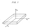
- Fig. 1 is a sectional view schematically showing the refractive indices of the three axes of the support.
- Fig. 2 is a sectional view of a metallizing apparatus employed in the case that the support is metallized in the fixed condition.
- Fig. 3 is a sectional view of a metallizing apparatus employed in the case that the support is continuously metallized to give a film.
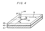
- Fig. 4 is a sectional view schematically showing the representative structure of the optically compensatory sheet employed for the liquid crystal display of the invention.
- Fig. 5 is a sectional view schematically showing the representative structure of the liquid crystal display of the invention.
- the liquid crystal display of the invention is characterized by the use of the novel optical compensatory sheet.
- the optical compensatory sheet of the invention can be prepared in the following manner:
- the optical compensatory sheet can be, for example, prepared by forming an orientation film on a transparent support and forming a layer from a discotic liquid crystal on the orientation film by coating method.
- any material can be employed so long as they are transparent.
- the material preferably has a transmittance of not less than 80 % and specially show optical isotropy when it is viewed from a front side.
- the support preferably has a negative uniaxial property and an optic axis in the normal line direction.
- the support is preferably prepared from materials having a small intrinsic birefringence, such as triacetyl cellulose.
- materials having a small intrinsic birefringence such as triacetyl cellulose.
- Such material is available on market by the trade name of Geonex (from Nippon Geon Co., Ltd.), Arton (from Japan Synthetic Rubber Co., Ltd.) and Fujitack (from Fuji Photo Film Co., Ltd.).
- materials having a large intrinsic birefringence such as polycarbonate, polyarylate, polysulfone and polyethersulfone can be also employed by rendering the materials optically isotropic through appropriately controlling molecular orientation in a procedure of forming a film.
- the transparent support preferably satisfies the condition of: 0 ⁇ nx + ny ⁇ d ⁇ 50 (nm) and more preferably: 0 ⁇ nx + ny ⁇ d ⁇ 20 (nm) in which nx and ny is main refractive indices within the support and d is a thickness direction of the support.
- the transparent support preferably satisfies the condition of: 20 ⁇ [(nx + ny)/2 - nz ⁇ ⁇ d ⁇ 300 (nm) in which nx and ny is main refractive indices in the plane of the support and nz is a main refractive index in a thickness direction of the support, whereby the viewing angle can be greatly increased.
- the transparent support preferably satisfies the condition of: 30 ⁇ [(nx + ny)/2 - nz ⁇ ⁇ d ⁇ 150 (nm)
- Fig. 1 shows "nx", “ny”, “nz” and “d” described above.
- "nx” and “ny” are main refractive indices on the plane of the support, “nz” is a main refractive index in a thickness direction of the transparent support and d is the thickness of the support.
- the orientation film is generally provided on the transparent support.
- any films can be employed so long as they are capable of imparting orientation property to a layer of liquid crystal.
- Preferred examples of the orientation film include a film of an organic compound (preferably polymer) subjected to rubbing treatment, an obliquely deposited film of an inorganic compound, and a film having micro grooves.
- LB film comprising an azobenzene derivative, that is isomerized by means of light to form a thin film of the molecules tilted uniformly in a certain direction, can be used as the orientation film.
- a layer prepared by orienting dielectric materials by application of electric field or magnetic field can be employed as the orientation film.
- orientation film examples include polyimide, polystyrene, gelatin, polyvinyl alcohol and polyvinyl alcohol having an alkyl group (preferably having 6 or more carbon atoms).
- Orientation films obtained by subjecting films of these polymers to orientation treatment, are capable of tilting obliquely discotic liquid crystal.
- the polyvinyl alcohol having an alkyl group is especially preferred from the viewpoint of uniform orientation of the discotic liquid crystal. It is presumed that interaction between the alkyl chain on the orientation film and the discotic liquid crystal gives high orientation.
- the alkyl group of the polyvinyl alcohol is preferably present as a side or terminal group of the polyvinyl alcohol, and especially as a terminal group.
- the alkyl group preferably has 6-14 carbon atoms, and the alkyl group is preferably attached to the polyvinyl alcohol through -S-, -(CH 3 )C(CN)-or -(C 2 H 5 )N-CS-S-.
- the polyvinyl alcohol preferably has a saponification value of not less than 80 % and a degree of polymerization of not less than 200.
- the polyvinyl alcohol having an alkyl group is available as trade names of MP103, MP203 and R1130 (produced by Kuraray Co., Ltd.)
- Preferred examples of the polyvinyl alcohol having an alkyl group are those having one of the following structures:
- Polyimide film which is widely used as an orientation film for a liquid crystal cell, is also preferably employed as the orientation film of the invention.
- the polyimide film can be prepared by coating a solution of polyamic (polyamide) acid (e.g., a series of LQ/LX available from Hitachi Chemical Co., Ltd.; and a series of SE available from Nissan Chemical Industries, Ltd.) on the transparent support, dried at 100 to 300°C for 0.5 to 1 hour, and rubbing a surface of the resultant polyimide film.
- polyamic (polyamide) acid e.g., a series of LQ/LX available from Hitachi Chemical Co., Ltd.; and a series of SE available from Nissan Chemical Industries, Ltd.
- the orientation film for the discotic liquid crystal can be rubbed in the known manner which is conventionally performed to prepare an orientation film for liquid crystal of LCD.
- the treatment is a method that gives a function of orienting a liquid crystal to a surface of the orientation film by rubbing the surface in a certain direction by the use of a paper, a gauze, a felt, a rubber, or a fiber of polyamide or polyester.
- the rubbing procedure is generally performed by rubbing a surface of the orientation film in several times using a cloth in which fibers having uniform length and width are arranged.
- the orientation film has a function of defining an orientation direction of a discotic liquid crystal provided thereon by a coating method.
- the orientation conditions of a discotic liquid crystal are dependent upon nature or the like of the orientation film, and therefore the discotic liquid crystal and the orientation film are needed to be combined in most appropriate conditions.
- a discotic liquid crystal uniformly oriented is tilted at a certain angle ( ⁇ ) to a surface of the support, whereas the angle scarcely depends on nature of the orientation film and mostly depends on nature or combination of discotic liquid crystals. Therefore, the angle can be finely controlled within a certain range by mixing two or more kinds of discotic liquid crystals or mixing a discotic liquid crystal and an anologous compound and at an appropriate mixed ratio.
- the angle of the oblique orientation is generally conducted by selecting the natures of discotic liquid crystals or mixing them.
- an obliquely deposited film of an inorganic compound is employable in the invention.
- the inorganic compounds include metal oxides or metal fluorides such as SiO, TiO 2 , MgF 2 and ZnO 2 and metals such as Au and Al.
- any compounds can be employed so long as they have high dielectric constant (permittivity).
- the obliquely deposited film of an inorganic compound can be prepared using the metallizing apparatus illustrated in Fig. 2 or 3.
- the metallizing apparatus of Fig. 2 is employed in the case that the support is metallized in the fixed condition, and the metallizing apparatus of Fig. 3 is employed in the case that the support is continuously metallized to give a film.
- Fig. 2 The metallizing apparatus of Fig. 2 is employed in the case that the support is metallized in the fixed condition
- the metallizing apparatus of Fig. 3 is employed in the case that the support is continuously metallized to give a film.
- vapor deposition at a deposition angle of 65 to 68 degree gives an orientation film on which a discotic liquid crystal is uniformly oriented in the direction where the deposited particle column and the optic axis of the discotic liquid crystal almost intersect at right angle.
- discotic liquid crystals employed in the invention include the following compounds:
- Compounds include benzene derivatives described in C. Destrade et al., Mol. Cryst. vol. 71, pp. 111, 1981, cyclohexane derivatives described in B. Kohn et al., Angew. Chem. vol. 96, pp. 70, 1984, macrocyclic compounds of azacrown-type or phenylacetylene-type described in J. M. Lehn et al., J. Chem. Commun. pp. 1794, 1985, and J. Zhang et al., J. Am. Chem. Soc. vol. 116, pp.2655, 1994.
- the discotic liquid crystal generally has a structure that the above compound is located at a center of the crystal as a parent core and further straight chain groups such as alkyl, alkoxy and benzoyl having a substituent are radially bonded to the compound.
- any discotic liquid crystals can be employed, so long as the liquid crystals have negative uniaxial property and orientation property.
- the layer prepared from a discotic liquid crystal of a low molecular weight of the invention includes a layer of discotic liquid crystal of a low molecular weight, and a layer formed by polymerizing and/or cross-linking a discotic liquid crystal having a functional group capable of reacting or polymerizing by means of heat or light.
- the polymerized liquid crystal has no liquid crystal property.
- the liquid crystal is stable at a temperature not higher than a transition temperature of from discotic liquid crystal phase to solid phase. Therefore, an optical anisotropy (optical compensatory sheet) containing the layer of the discotic liquid crystal is stable to heat.
- LCD to be loaded on a vehicle needs excellent heat-resistance.
- the layer of discotic liquid crystal formed by polymerizing and/or cross-linking mentioned above exhibits excellent heat-resistance, and therefore an optical compensatory sheet containing such layer is preferably used for LCD to be used in a motor car or other vehicles.
- n 2 and n 3 are not required to be strictly equal to each other and it will be satisfied that they are approximately equal to each other.
- the optic axis of the layer of the discotic liquid crystal is preferably inclined at 5 to 50 degrees to a normal line of the sheet (shown by ⁇ in Fig. 4), more preferably at 10 to 40 degrees, and especially 20 to 35 degrees.
- the optical compensatory sheet employed in the invention obtained in the above manner is greatly improved in coloring of a displayed image and reversing of black-and-white image when the viewing direction is greatly inclined to upper or lower, or right or left to the normal to a surface of the display.
- the liquid crystal display provided with the optical compensatory sheet shows excellent viewing characteristics such as enlargement of viewing angle.
- optical compensatory sheet employed in the invention gives much increase of viewing angle.
- TN-LCD adopt normally white mode.
- a light transmittance in a black display portion extremely increases with increase of viewing angle, which results in rapid reduction of contrast.
- black display the condition where voltage is applied
- TN-type liquid crystal cell shows an optically anisotropic property and a positive uniaxial property which is slightly inclined from a normal line to a surface of the cell.
- an optic axis of the TN-type liquid crystal cell is inclined from the normal line to a surface of the cell
- use of a optically anisotropic substance having an optic axis in a normal line direction is considered not to appropriately compensate the phase difference by the cell.
- an optically anisotropic substance is needed for the cell to have an optic axis inclined from the normal line.
- an optically anisotropic substance having a negative uniaxial property is suitably used for compensation of phase difference by the cell.
- use of an optically anisotropic substance of a negative uniaxial property having optic axis inclined from the normal line improves viewing angle characteristics.
- the liquid crystal cell behaves as optically anisotropic substance with a positive uniaxial property having optic axis inclined from the normal line. Therefore, use of the optically anisotropic substance does not give satisfactorily compensation of phase difference.
- the TN-type liquid crystal cell can be regarded as a composite of two optically anisotropic substances having a positive uniaxial property which has a inclined angle equal to each other and inclination direction differing from each other.
- optic axes of the optically anisotropic substances are further inclined from the normal line to a surface of the cell.
- the optical compensatory sheet which is prepared by, for example, superposing an optical anisotropic substance (element) having an optically negative monoaxial and an inclined optic axis (preferably inclined at 5 to 50 degree to the normal), on an optically anisotropic substance (element) having an optically negative monoaxial and an optic axis in the normal direction.
- Such optical compensatory sheet is included in an optical compensatory sheet having the incident direction of light showing the minimum of absolute values of retardation values in a direction inclined from the normal of the sheet and having no optic axis (i.e., an optical compensatory sheet having an optical anisotropy wherein the minimum of absolute values of retardation values in the directions at all angles to the normal of the sheet is not present in the normal direction and a surface direction of the sheet and the Re value is not zero in any directions).
- the optically compensatory sheet employed in the invention which contains the above optically compensatory sheet, can be easily prepared by coating a coating solution for forming an orientation film on a transparent film (preferably having a negative uniaxial property and an optic axis in the normal line direction), and then coating a solution containing a discotic liquid crystal on the orientation film in thin thickness.
- the oblique orientation is preferably performed by coating a solution containing the discotic liquid crystal on an orientation film subjected to orientation treatment provided on the transparent support to form a layer of the discotic liquid crystal, and then heating the layer to a temperature forming discotic nematic liquid crystal phase. This heating brings about the orientation of the discotic liquid crystal. Thereafter, the layer is cooled with maintaining the orientation to room temperature and the layer is made solid.
- the temperature forming discotic nematic liquid crystal phase is an inherent value (temperature) of the discotic nematic liquid crystal
- the temperature can be controlled within a desired range by mixing two or more kinds of discotic liquid crystals and changing the mixed ratio.
- the temperature forming discotic nematic liquid crystal phase preferably is in the range of 70 to 300°C, and especially in the range of 70 to 150°C.
- a transparent support 41, an orientation film 42 and a layer of discotic liquid crystal 43 are superposed in order to constitute the optically compensatory sheet.
- the reference sign R indicates the rubbing direction of the orientation film.
- the reference signs n 1 , n 2 and n 3 indicate refractive indices in the three axes direction of a discotic liquid crystal, and n 1 , n 2 and n 3 satisfy the condition of n 1 ⁇ n 2 ⁇ n 3 , in the case that are seen in the front direction.
- the reference sign ⁇ is an inclined angle of the optic axis to the normal 44 of the layer of the discotic liquid crystal.
- a liquid crystal cell TNC comprising a pair of substrates provided with a transparent electrode and a twist-oriented nematic liquid crystal sealed therebetween, a pair of polarizing sheets A and B arranged on the both sides of the cell, the optical compensatory sheets RF1 and RF 2 between the liquid crystal cell and the polarizing sheet and back light BL are assembled to constitute the liquid crystal display.
- the optical compensatory sheet may be arranged only on one side (i.e., use of one of RF1 and RF 2 ).
- the reference number R1 is a rubbing direction of the orientation film of the optical compensatory sheets RF1
- the reference number R2 is the rubbing direction of the orientation film of the optical compensatory sheets RF2, in the case that are seen in the front direction.
- PA and PB are polarizing axes of polarizing sheets A and B, respectively.
- any known materials can be employed so long as they are TN-CL or STN-CL.
- materials of the polarizing sheet employed for the liquid crystal cell any known materials can be employed so long as they have polarizing property.
- Triacetyl cellulose (weight-average molecular weight: 130,000, in terms of polystyrene) was dissolved in dichloromethane to prepare a copolymer solution. The polymer solution was casted on a stainless belt and peeled off to prepare a film. Then, the film was stretched in a widthwise direction and in a lengthwise (MD) direction and subjected to orientation relaxation by heating. Thus, triacetyl cellulose films having various surface orientation (TF-1 to TF-5) were prepared.
- the thickness was measured with a micrometer, Re value in front direction was measured by an ellipsometer (AEP-100, available from Shimadzu Seisakusho, Ltd.) to regard the value as "(nx - ny) ⁇ d", and "(nx + ny)/2 - nz” was determined by measuring "ny” with Abbe refractometer and calculating "(nx + ny)/2 - nz” using the value of "ny” and "nz” calculated from Re values measured at various angles. Further, as for PES of Example 12 and TF-6 of Example 14 as described later, the above measurements were performed.
- TF-1 triacetyl cellulose film
- a thin layer of gelatin 0.1 ⁇ m
- a coating solution containing polyvinyl alcohol having long chain alkyl groups MP-203, produced by Kuraray Co., Ltd. was coated on the gelatin layer, dried using warm air to form a layer of the polyvinyl alcohol and rubbing a surface of the layer to form an orientation film.
- Example 1 The procedure of Example 1 was repeated except for using a glass plate (thickness: 1 mm) showing optically isotropy in place of the triacetyl cellulose film to prepare an optical compensatory sheet (RG-1).
- Example 2 The procedure of Example 2 was repeated except for forming no gelatin layer and changing the ratio of the discotic liquid crystal TE-8-(3) and the discotic liquid crystal TE-8-(5) from 9:1 to 4:1 to prepare an optical compensatory sheet (RG-2).
- Example 1 The procedure of Example 1 was repeated except for using the triacetyl cellulose film of TF-3 and changing the ratio of the discotic liquid crystal TE-8-(3) and the discotic liquid crystal TE-8-(5) from 9:1 to 4:1 to prepare an optical compensatory sheet (RTF-6).
- Example 2 The procedure of Example 2 was repeated except for forming no gelatin layer, changing the concentration of the coating solution of the discotic liquid crystals from 10 % to 7 % and changing a thickness of the layer of discotic liquid crystal from 1.0 ⁇ m to 0.7 ⁇ m to prepare an optical compensatory sheet (RG-4).
- Example 1 The procedure of Example 1 was repeated except for using the triacetyl cellulose film of TF-3, changing the concentration of the coating solution of the discotic liquid crystals from 10 % to 7 % and changing a thickness of the layer of discotic liquid crystal from 1.0 ⁇ m to 0.7 ⁇ m to prepare an optical compensatory sheet (RTF-8).
- Example 2 The procedure of Example 2 was repeated except for forming no gelatin layer, changing the concentration of the coating solution of the discotic liquid crystals from 10 % to 20 % and changing a thickness of the layer of discotic liquid crystal from 1.0 ⁇ m to 2.0 ⁇ m to prepare an optical compensatory sheet (RG-5).
- Example 1 The procedure of Example 1 was repeated except for using the triacetyl cellulose film of TF-3, changing the concentration of the coating solution of the discotic liquid crystals from 10 % to 20 % and changing a thickness of the layer of discotic liquid crystal from 1.0 ⁇ m to 2.0 ⁇ m to prepare an optical compensatory sheet (RTF-9).
- a coating solution of polyamic acid SE-7210, available from Nissan Chemical Industries, Ltd. was coated, burned at 180°C to form a polyimide layer and rubbing a surface of the layer to form an orientation film.
- a coating solution of 10 weight % obtained by dissolving the discotic liquid crystal TE-8-(4) (compounds previously mentioned) in methyl ethyl ketone was coated at 2,000 rpm using a spin-coater. Thereafter, the coated layer was heated to 180°C in a thermostat, subjected to heat treatment and cooled to room temperature to form a layer of the discotic liquid crystal having a thickness of 1.0 ⁇ m. Thus, an optical compensatory sheet (RG-6) was obtained.
- Example 11 The procedure of Example 11 was repeated except for using a polyethersulfone film (PES) of a thickness of 100 ⁇ m (FS-1300, available from Sumitomo Bakelite Co., Ltd.) having in place of the glass plate to prepare an optical compensatory sheet (RTF-10).
- PES polyethersulfone film
- FS-1300 available from Sumitomo Bakelite Co., Ltd.
- SiO was obliquely deposited using the continuous metallizing apparatus shown in Fig. 5 to form an orientation film.
- the deposition was conducted under the conditions of film feeding rate of 10 m/minute, deposition source temperature of 1800K and minimum deposition angle of 85 degrees.
- a coating solution of 10 weight % obtained by dissolving the discotic liquid crystal TE-9-(1) (compounds previously mentioned) in methyl ethyl ketone was coated at 2,000 rpm using a spin-coater. Thereafter, the coated layer was heated to 150°C, subjected to heat treatment and cooled to room temperature to form a layer of the discotic liquid crystal having a thickness of 1.0 ⁇ m. Thus, an optical compensatory sheet (RG-7) was obtained.
- Example 13 The procedure of Example 13 was repeated except for using a triacetyl cellulose film of a thickness of 85 ⁇ m (TF-6.) having a gelatin layer (0.1 ⁇ m) on the orientation film side of the film and an antistatic layer on the back of the film in place of the glass plate to prepare an optical compensatory sheet (RTF-11).
- TF-6. triacetyl cellulose film of a thickness of 85 ⁇ m
- RTF-11 optical compensatory sheet
- a coating solution containing polyvinyl alcohol having long chain alkyl groups (MP-203, produced by Kuraray Co., Ltd.) was coated, dried using warm air to form a layer of the polyvinyl alcohol and rubbing a surface of the layer to form an orientation film.
- Example 15 The procedure of Example 15 was repeated except for using a triacetyl cellulose film of a thickness of 85 ⁇ m (TF-6) having a gelatin layer (0.1 ⁇ m) on the film in place of the glass plate to prepare an optical compensatory sheet (RTF-12).
- TF-6 triacetyl cellulose film of a thickness of 85 ⁇ m
- RTF-12 optical compensatory sheet
- the angle ( ⁇ ) where the optic axis and the normal line of the sheet intersect and ⁇ n•D was determined by calculating from Re values measured at various angles. The measurement was conducted using an ellipsometer (AEP-100, available from Shimadzu Seisakusho, Ltd.) in transmission mode.
- Each of the optical compensatory sheets obtained in Examples 1-16 was attached to TN-type liquid crystal cell that the product of the difference between an extraordinary ray and an ordinary ray of the liquid crystal and the clearance between the substrats of the liquid crystal cell was 500 nm, and the twisted angle of the liquid crystal was 90 degrees.
- the obtained TN-LCD has a structure shown in Fig. 5.
- TN-LCD To the TN-LCD, a rectangular wave of 40 Hz was applied at a voltage of 0 to 50 V, and transmittances (T) were measured by varying viewing angle using a spectrophotometer (LCD-5000, available from Otsuka Electronics Co., Ltd.). From the measured data, viewing angles in a upper-lower direction and a left-right direction were determined. The viewing angle was defined as the viewing angle that contrast (T 1V /T 5V ) in black-and-white display shows 10.
- each of the sheets has no optic axis and has the incident direction of light showing the minimum of absolute values of retardation values in a direction inclined from the normal of the sheet.
- Example 17 The procedure of Example 17 was repeated except for using no optical compensatory sheet and the supports (TF-1 to TF-5) obtained in Examples 1 in place of the optical compensatory sheet to prepare six kinds of TN-LCD.
- Optical characteristics such as viewing angles in a upper-lower direction and a left-right direction were determined in the same manner as Example 17.
Description
- The present invention relates to a liquid crystal display provided with an optically compensatory sheet.
- As a display for electronic office system-devices such as a desk-top personal computer and a word processor for Japanese language, CRT (cathode ray tube) has been employed so far. Recently, a liquid crystal display (hereinafter referred to as LCD) is increasingly employed instead of the CRT because of its thin thickness, light weight and low power consumption. LCD generally has a structure that a liquid crystal cell is disposed between a pair of polarizing sheets. Most of LCD use a twisted nematic liquid crystal. Operational mode of LCD using the twisted nematic liquid crystal is roughly divided into birefringence mode and optical rotatory mode.
- A super twisted nematic liquid crystal display (hereinafter referred to as STN-LCD) utilizing the birefringence mode uses a super twisted nematic liquid crystal showing a twisted angle of more than 90 degrees and having steep electro-optical characteristics. Such STN-LCD, therefore, has an advantage of giving display of a large capacity by driving in time-sharing mode. However, the STN-LCD has disadvantages such as slow response (several hundred milliseconds) and difficulty in giving satisfactory gradation on display, and therefore its display characteristics are relatively poor, as compared with display characteristics of a liquid crystal display using the known active-type elements (e.g., TFT-LCD and MIM-LCD).
- In the TFT-LCD and MIM-LCD, twisted nematic liquid crystal showing a twisted angle of 90 degrees is employed for displaying an image. This is called LCD of an optically rotary mode (i.e., TN-LCD). TN-LCD display mode shows fast response (several tens of milliseconds) and high display contrast, and easily gives black-white display of high contrast. Hence, the optical rotatory mode has a number of advantages compared with the birefringence mode or other modes. However, TN-LCD has disadvantages that color or contrast on display varies depending upon viewing direction to a liquid crystal display, and its display characteristics are not comparable to display characteristics of CRT.
- In order to improve the viewing angle characteristics (i.e. to enlarge the viewing angle), arrangement of a phase difference film (optically compensatory sheet) between a pair of polarizing plates and TN liquid crystal cell has been proposed in Japanese Patent Provisional Publications No. 4(1992)-229828 and No. 4(1992)-258923.
- The phase difference films proposed in these Publications show no optical effect when seen from the direction vertical to a screen of a liquid crystal display because phase difference in the direction perpendicular to a surface of the liquid crystal display is almost zero. However, the phase difference film serves for compensation of phase difference (depending upon wavelengths of light) that occurs when the liquid crystal display is viewed from an oblique direction. The phase difference results in unfavorable viewing angle characteristics such as coloring and disappearance of displayed image.
- Even a liquid crystal display provided with such phase difference film is still not improved particularly in coloring of a displayed image and reversing of black-and-white image when the viewing direction to the liquid crystal display is greatly inclined to upper or lower, or right or left to the normal to a surface of the screen. Thus, such liquid crystal display cannot be employed instead of CRT, and further is not suitable for loading in a vehicle.
- Japanese Patent Provisional Publications No. 4(1992)-366808 and No. 4(1992)-366809 disclose a difference phase film of a liquid crystal cell comprising a chiral nematic liquid crystal that an optic axis is inclined to enlarge the viewing angle. The difference phase film is composed of two liquid crystal cells, and therefore needs a complicated process for its preparation and brings about increase of its weight.
- Japanese Patent Provisional Publications No. 4(1992)-113301 and No. 5(1993)-157913 disclose a phase difference film of chain polymer whose optic axis or an optical elastic axis is inclined from a surface of a liquid crystal cell. The phase difference film is prepared by slicing obliquely a uniaxial polycarbonate film, and therefore a phase difference film of a large area cannot be easily prepared according to the disclosed process. Further, the publications are for inventions with regard to STN-LCD and therefore give no teachings as to the use with TN-LCD.
- Japanese Patent Provisional Publication No. 5(1993)-215921 discloses the use of a birefringence plate comprising a pair of supports and a rod-like compound showing liquid crystal property. The rod-like compound showing liquid crystal property is prepared by interposing and curing the compound to give a compensate difference phase of LCD. However, the birefringence plate has the same structure as one of the two liquid crystal cell as mentioned above, and therefore needs a complicated process for its preparation, which is not suitable for mass production. Further, its structure brings about increase of weight. Furthermore, the publications are for inventions with regard to STN-LCD and therefore give no teachings as to the use for TN-LCD.
- Japanese Patent Provisional Publications No. 3(1991)-9326 and No. 3(1991)-291601 disclose an optically compensatory sheet for LCD which is prepared by coating a solution of a polymer showing liquid crystal property on an alignment film provided on a support film. However, the polymer showing liquid crystal property is not satifactorily oriented on the alignment film. Hence, the resulting compensatory scarcely enlarges the viewing angle from all directions.
- EP 0576342 A1 which forms prior art under Art 54(3) EPC discloses a phase difference plate comprising a material having optical anisotropy in a flat plate in which the direction of the principal refractive index of the index ellipsoid is inclined to the normal of the surface. The disclosed phase difference plate shows great enlargement of the viewing angle compared with other known phase difference films as mentioned above. However, LCD provided with such phase difference plate is not comparable to CRT in the viewing angle characteristics.
- Compensating layers for LCD comprising discotic liquid crystal material are known from WO90/16005.
- EP-A-0 367 288 discloses LCDs with two compensating layers as specified in the preamble of claim 8, one of these layers having an optical axis normal to the layer.
- It is an object of the present invention to provide a liquid crystal display provided with a novel optical compensatory sheet greatly improved in coloring of a displayed image and reversing of black-and-white image when the viewing direction to the liquid crystal display is greatly inclined to upper or lower, or right or left to the normal to a surface of the screen.
- There is provided by the invention a liquid crystal display comprising a liquid crystal cell which comprises a pair of substrates provided with a transparent electrode and twist-oriented nematic liquid crystal sealed therebetween, a pair of polarizing sheets arranged on both sides of the cell, and an optical compensatory sheet provided between the liquid crystal cell and at least one of the polarizing sheet;
wherein the optical compensatory sheet comprises, in order, a transparent support, an orientation film and a layer provided thereon which is prepared from a discotic liquid crystal of a low molecular weight and which has an optic axis inclined from the normal of the layer. - Preferred embodiments of the liquid crystal display of the present invention are as follows:
- 1) The liquid crystal display wherein the layer of a discotic liquid crystal has an optic axis inclined at 5 to 50 degrees to the normal (i.e., normal line) of the layer.
- 2) The liquid crystal display wherein the orientation film is a polymer film which has been subjected to rubbing treatment.
- 3) The liquid crystal display wherein the orientation film is a film of polyvinyl alcohol having an alkyl group which has been subjected to rubbing treatment
- 4) The liquid crystal display wherein the orientation film is prepared by obliquely depositing an inorganic compound on the support.
- 5) The liquid crystal display wherein the
transparent support has a light transmittance of not less
than 80 %, shows optically isotropy on the plane of the
support, and satisfies the condition of:
- 6) The liquid crystal display wherein the transparent support is a triacetyl cellulose film.
- 7) The liquid crystal display wherein the transparent support has a negative uniaxial property and an optic axis in the normal line direction.
-
- There is further provided by the invention a liquid crystal display comprising a liquid crystal cell which comprises a pair of substrates provided with a transparent electrode and twist-oriented nematic liquid crystal sealed therebetween, a pair of polarizing sheets arranged on both sides of the cell, and an optical compensatory sheet provided between the liquid crystal cell and the polarizing sheet;
wherein the optical compensatory sheet has the minimum of absolute values of retardation values in a direction inclined from the normal of the sheet and has no optic axis, and wherein the optical compensatory sheet comprises two elements having optical anisotropy and optical characteristics differing from each other, in which one of the elements has an optically negative monoaxial and an optic axis in the normal direction of the element, and the other element has an optically negative monoaxial and an optic axis inclined at 5 to 50 degrees to the normal of the element. - Preferred embodiments of the liquid crystal display of the present invention are as follows:
- 1) The liquid crystal display wherein the element having an optically negative monoaxial which is inclined at 5 to 50 degrees to the normal of the film is a layer prepared from a discotic liquid crystal of a low molecular weight.
- 2) The liquid crystal display wherein wherein the
element having an optically negative monoaxial and an optic
axis in the normal direction has a light transmittance of
not less than 80 %, shows optically isotropy on the plane
of the support, and satisfies the condition of:
- 3) The liquid crystal display wherein the element having an optically negative monoaxial and an optic axis in the normal direction is a triacetyl cellulose film.
-
- The optical compensatory sheet employed for the liquid crystal display of the invention is advantageously prepared by a process of the invention comprising the steps of:
- forming an orientation film on a transparent support,
- forming a layer prepared from a discotic liquid crystal (of a low molecular weight) on the orientation film by coating method, and
- heating the layer of a discotic liquid crystal at a temperature of not less than a transition temperature of from the liquid crystal phase to the solid phase.
-
- The optical compensatory sheet employed for the liquid crystal display of the invention is greatly improved in coloring of a displayed image and reversal of black-and-white when the viewing direction is greatly inclined in an upper-lower or light-left direction to the normal to a surface of the screen. Thus, the liquid crystal display provided with the optical compensatory sheet shows excellent viewing characteristics such as much increase of viewing angle.
- Fig. 1 is a sectional view schematically showing the refractive indices of the three axes of the support.
- Fig. 2 is a sectional view of a metallizing apparatus employed in the case that the support is metallized in the fixed condition.
- Fig. 3 is a sectional view of a metallizing apparatus employed in the case that the support is continuously metallized to give a film.
- Fig. 4 is a sectional view schematically showing the representative structure of the optically compensatory sheet employed for the liquid crystal display of the invention.
- Fig. 5 is a sectional view schematically showing the representative structure of the liquid crystal display of the invention.
- The liquid crystal display of the invention is characterized by the use of the novel optical compensatory sheet. The optical compensatory sheet of the invention can be prepared in the following manner:
- The optical compensatory sheet can be, for example, prepared by forming an orientation film on a transparent support and forming a layer from a discotic liquid crystal on the orientation film by coating method.
- As material of the transparent support of the invention, any material can be employed so long as they are transparent. The material preferably has a transmittance of not less than 80 % and specially show optical isotropy when it is viewed from a front side. Further, the support preferably has a negative uniaxial property and an optic axis in the normal line direction.
- Therefore, the support is preferably prepared from materials having a small intrinsic birefringence, such as triacetyl cellulose. Such material is available on market by the trade name of Geonex (from Nippon Geon Co., Ltd.), Arton (from Japan Synthetic Rubber Co., Ltd.) and Fujitack (from Fuji Photo Film Co., Ltd.).
- However, materials having a large intrinsic birefringence such as polycarbonate, polyarylate, polysulfone and polyethersulfone can be also employed by rendering the materials optically isotropic through appropriately controlling molecular orientation in a procedure of forming a film.
- The transparent support preferably satisfies the condition of:
- Especially, the transparent support preferably satisfies the condition of:
- Fig. 1 shows "nx", "ny", "nz" and "d" described above. "nx" and "ny" are main refractive indices on the plane of the support, "nz" is a main refractive index in a thickness direction of the transparent support and d is the thickness of the support.
- The orientation film is generally provided on the transparent support. As the orientation film, any films can be employed so long as they are capable of imparting orientation property to a layer of liquid crystal. Preferred examples of the orientation film include a film of an organic compound (preferably polymer) subjected to rubbing treatment, an obliquely deposited film of an inorganic compound, and a film having micro grooves. Further, LB film comprising an azobenzene derivative, that is isomerized by means of light to form a thin film of the molecules tilted uniformly in a certain direction, can be used as the orientation film. In addition, a layer prepared by orienting dielectric materials by application of electric field or magnetic field can be employed as the orientation film.
- Examples of polymers for the orientation film include polyimide, polystyrene, gelatin, polyvinyl alcohol and polyvinyl alcohol having an alkyl group (preferably having 6 or more carbon atoms). Orientation films obtained by subjecting films of these polymers to orientation treatment, are capable of tilting obliquely discotic liquid crystal.
- The polyvinyl alcohol having an alkyl group is especially preferred from the viewpoint of uniform orientation of the discotic liquid crystal. It is presumed that interaction between the alkyl chain on the orientation film and the discotic liquid crystal gives high orientation. The alkyl group of the polyvinyl alcohol is preferably present as a side or terminal group of the polyvinyl alcohol, and especially as a terminal group. The alkyl group preferably has 6-14 carbon atoms, and the alkyl group is preferably attached to the polyvinyl alcohol through -S-, -(CH3)C(CN)-or -(C2H5)N-CS-S-. The polyvinyl alcohol preferably has a saponification value of not less than 80 % and a degree of polymerization of not less than 200. The polyvinyl alcohol having an alkyl group is available as trade names of MP103, MP203 and R1130 (produced by Kuraray Co., Ltd.)
- Preferred examples of the polyvinyl alcohol having an alkyl group are those having one of the following structures:


- Polyimide film, which is widely used as an orientation film for a liquid crystal cell, is also preferably employed as the orientation film of the invention. The polyimide film can be prepared by coating a solution of polyamic (polyamide) acid (e.g., a series of LQ/LX available from Hitachi Chemical Co., Ltd.; and a series of SE available from Nissan Chemical Industries, Ltd.) on the transparent support, dried at 100 to 300°C for 0.5 to 1 hour, and rubbing a surface of the resultant polyimide film.
- The orientation film for the discotic liquid crystal can be rubbed in the known manner which is conventionally performed to prepare an orientation film for liquid crystal of LCD. In more detail, the treatment is a method that gives a function of orienting a liquid crystal to a surface of the orientation film by rubbing the surface in a certain direction by the use of a paper, a gauze, a felt, a rubber, or a fiber of polyamide or polyester. The rubbing procedure is generally performed by rubbing a surface of the orientation film in several times using a cloth in which fibers having uniform length and width are arranged.
- The orientation film has a function of defining an orientation direction of a discotic liquid crystal provided thereon by a coating method. The orientation conditions of a discotic liquid crystal are dependent upon nature or the like of the orientation film, and therefore the discotic liquid crystal and the orientation film are needed to be combined in most appropriate conditions.
- For example, a discotic liquid crystal uniformly oriented is tilted at a certain angle () to a surface of the support, whereas the angle scarcely depends on nature of the orientation film and mostly depends on nature or combination of discotic liquid crystals. Therefore, the angle can be finely controlled within a certain range by mixing two or more kinds of discotic liquid crystals or mixing a discotic liquid crystal and an anologous compound and at an appropriate mixed ratio. Thus, the angle of the oblique orientation is generally conducted by selecting the natures of discotic liquid crystals or mixing them.
- As the orientation film, an obliquely deposited film of an inorganic compound is employable in the invention. Examples of the inorganic compounds include metal oxides or metal fluorides such as SiO, TiO2, MgF2 and ZnO2 and metals such as Au and Al. As the inorganic compound, any compounds can be employed so long as they have high dielectric constant (permittivity). The obliquely deposited film of an inorganic compound can be prepared using the metallizing apparatus illustrated in Fig. 2 or 3. The metallizing apparatus of Fig. 2 is employed in the case that the support is metallized in the fixed condition, and the metallizing apparatus of Fig. 3 is employed in the case that the support is continuously metallized to give a film. In Fig. 2, the support S1 is arranged in a such a manner that an angle where a normal line of the support S1 and the evaporating direction from an evaporation source T1 intersect becomes α1 (α1 =88-30 degrees). In Fig. 3, the support film S2 is arranged in a such a manner that an angle where a normal line of a tangent line of the support film S2 and the evaporating direction from an evaporation source T2 intersect becomes α2 (α2 =88-30 degrees). In the case of using SiO2 as the evaporation material, vapor deposition at a deposition angle of 65 to 68 degree gives an orientation film on which a discotic liquid crystal is uniformly oriented in the direction where the deposited particle column and the optic axis of the discotic liquid crystal almost intersect at right angle.
- Examples of the discotic liquid crystals employed in the invention include the following compounds:
- Compounds include benzene derivatives described in C. Destrade et al., Mol. Cryst. vol. 71, pp. 111, 1981, cyclohexane derivatives described in B. Kohn et al., Angew. Chem. vol. 96, pp. 70, 1984, macrocyclic compounds of azacrown-type or phenylacetylene-type described in J. M. Lehn et al., J. Chem. Commun. pp. 1794, 1985, and J. Zhang et al., J. Am. Chem. Soc. vol. 116, pp.2655, 1994. The discotic liquid crystal generally has a structure that the above compound is located at a center of the crystal as a parent core and further straight chain groups such as alkyl, alkoxy and benzoyl having a substituent are radially bonded to the compound. As the discotic liquid crystals, any discotic liquid crystals can be employed, so long as the liquid crystals have negative uniaxial property and orientation property.
- Preferred examples of the discotic liquid crystals employable in the invention are described below.


 or
or

- The layer prepared from a discotic liquid crystal of a low molecular weight of the invention includes a layer of discotic liquid crystal of a low molecular weight, and a layer formed by polymerizing and/or cross-linking a discotic liquid crystal having a functional group capable of reacting or polymerizing by means of heat or light. The polymerized liquid crystal has no liquid crystal property.
- In the case that the discotic liquid crystal is once oriented on the orientation film, the liquid crystal is stable at a temperature not higher than a transition temperature of from discotic liquid crystal phase to solid phase. Therefore, an optical anisotropy (optical compensatory sheet) containing the layer of the discotic liquid crystal is stable to heat. LCD to be loaded on a vehicle needs excellent heat-resistance. The layer of discotic liquid crystal formed by polymerizing and/or cross-linking mentioned above exhibits excellent heat-resistance, and therefore an optical compensatory sheet containing such layer is preferably used for LCD to be used in a motor car or other vehicles.
- The negative uniaxial property of the invention, that the layer of the discotic liquid crystal generally has, means property as satisfies the condition of:
- In order to greatly improve viewing angle characteristics of TN-LCD or TFT-LCD, the optic axis of the layer of the discotic liquid crystal is preferably inclined at 5 to 50 degrees to a normal line of the sheet (shown by β in Fig. 4), more preferably at 10 to 40 degrees, and especially 20 to 35 degrees.
- Further, it is preferred that the discotic liquid crystal layer satisfies the condition of:
- The optical compensatory sheet employed in the invention obtained in the above manner is greatly improved in coloring of a displayed image and reversing of black-and-white image when the viewing direction is greatly inclined to upper or lower, or right or left to the normal to a surface of the display. Thus, the liquid crystal display provided with the optical compensatory sheet shows excellent viewing characteristics such as enlargement of viewing angle.
- The reason why the optical compensatory sheet employed in the invention gives much increase of viewing angle is assumed as follows:
- Most of TN-LCD adopt normally white mode. In the mode, a light transmittance in a black display portion extremely increases with increase of viewing angle, which results in rapid reduction of contrast. In the condition of black display (the condition where voltage is applied), it is considered that TN-type liquid crystal cell shows an optically anisotropic property and a positive uniaxial property which is slightly inclined from a normal line to a surface of the cell.
- In the case that an optic axis of the TN-type liquid crystal cell is inclined from the normal line to a surface of the cell, use of a optically anisotropic substance having an optic axis in a normal line direction is considered not to appropriately compensate the phase difference by the cell. In other words, an optically anisotropic substance is needed for the cell to have an optic axis inclined from the normal line. Further, when the cell is regarded as a composite of optically anisotropic substances with a positive uniaxial property, an optically anisotropic substance having a negative uniaxial property is suitably used for compensation of phase difference by the cell. Thus, use of an optically anisotropic substance of a negative uniaxial property having optic axis inclined from the normal line improves viewing angle characteristics.
- However, it is mere approximation that the liquid crystal cell behaves as optically anisotropic substance with a positive uniaxial property having optic axis inclined from the normal line. Therefore, use of the optically anisotropic substance does not give satisfactorily compensation of phase difference.
- From study of the inventors, it has been discovered that the TN-type liquid crystal cell can be regarded as a composite of two optically anisotropic substances having a positive uniaxial property which has a inclined angle equal to each other and inclination direction differing from each other. When an intermediate gradation is displayed, optic axes of the optically anisotropic substances are further inclined from the normal line to a surface of the cell.
- In the case that the TN-type liquid crystal cell is considered as above, great improvement of viewing angle characteristics can be obtained by employing the optical compensatory sheet which is prepared by, for example, superposing an optical anisotropic substance (element) having an optically negative monoaxial and an inclined optic axis (preferably inclined at 5 to 50 degree to the normal), on an optically anisotropic substance (element) having an optically negative monoaxial and an optic axis in the normal direction.
- Such optical compensatory sheet is included in an optical compensatory sheet having the incident direction of light showing the minimum of absolute values of retardation values in a direction inclined from the normal of the sheet and having no optic axis (i.e., an optical compensatory sheet having an optical anisotropy wherein the minimum of absolute values of retardation values in the directions at all angles to the normal of the sheet is not present in the normal direction and a surface direction of the sheet and the Re value is not zero in any directions).
- As described previously, the optically compensatory sheet employed in the invention, which contains the above optically compensatory sheet, can be easily prepared by coating a coating solution for forming an orientation film on a transparent film (preferably having a negative uniaxial property and an optic axis in the normal line direction), and then coating a solution containing a discotic liquid crystal on the orientation film in thin thickness. In the process, it is required to obliquely and uniformly orient the discotic liquid crystal. In more detail, the oblique orientation is preferably performed by coating a solution containing the discotic liquid crystal on an orientation film subjected to orientation treatment provided on the transparent support to form a layer of the discotic liquid crystal, and then heating the layer to a temperature forming discotic nematic liquid crystal phase. This heating brings about the orientation of the discotic liquid crystal. Thereafter, the layer is cooled with maintaining the orientation to room temperature and the layer is made solid.
- Although the temperature forming discotic nematic liquid crystal phase is an inherent value (temperature) of the discotic nematic liquid crystal, the temperature can be controlled within a desired range by mixing two or more kinds of discotic liquid crystals and changing the mixed ratio. The temperature forming discotic nematic liquid crystal phase preferably is in the range of 70 to 300°C, and especially in the range of 70 to 150°C.
- The representative structure of the optically compensatory sheet employed in the invention is shown in Fig. 4. In Fig. 4, a
transparent support 41, anorientation film 42 and a layer of discoticliquid crystal 43 are superposed in order to constitute the optically compensatory sheet. The reference sign R indicates the rubbing direction of the orientation film. The reference signs n1, n2 and n3 indicate refractive indices in the three axes direction of a discotic liquid crystal, and n1, n2 and n3 satisfy the condition of n1 ≤ n2 ≤ n3, in the case that are seen in the front direction. The reference sign β is an inclined angle of the optic axis to the normal 44 of the layer of the discotic liquid crystal. - The representative structure of the liquid crystal display of the invention is shown in Fig. 5. In Fig. 5, a liquid crystal cell TNC comprising a pair of substrates provided with a transparent electrode and a twist-oriented nematic liquid crystal sealed therebetween, a pair of polarizing sheets A and B arranged on the both sides of the cell, the optical compensatory sheets RF1 and RF2 between the liquid crystal cell and the polarizing sheet and back light BL are assembled to constitute the liquid crystal display. The optical compensatory sheet may be arranged only on one side (i.e., use of one of RF1 and RF2). The reference number R1 is a rubbing direction of the orientation film of the optical compensatory sheets RF1, and the reference number R2 is the rubbing direction of the orientation film of the optical compensatory sheets RF2, in the case that are seen in the front direction. PA and PB are polarizing axes of polarizing sheets A and B, respectively.
- As materials of liquid crystal employed for the liquid crystal cell, any known materials can be employed so long as they are TN-CL or STN-CL. As materials of the polarizing sheet employed for the liquid crystal cell, any known materials can be employed so long as they have polarizing property.
- Examples of the present invention and comparison examples are given below, but these examples by no means restrict the invention.
- Triacetyl cellulose (weight-average molecular weight: 130,000, in terms of polystyrene) was dissolved in dichloromethane to prepare a copolymer solution. The polymer solution was casted on a stainless belt and peeled off to prepare a film. Then, the film was stretched in a widthwise direction and in a lengthwise (MD) direction and subjected to orientation relaxation by heating. Thus, triacetyl cellulose films having various surface orientation (TF-1 to TF-5) were prepared.
- "(nx - ny) × d" and "(nx + ny)/2 - nz" of the prepared films were determined, in which nx and ny is main refractictive indices within the film, nz is a main refractive index in a thickness direction, and d is a thickness of the film.
- The thickness was measured with a micrometer, Re value in front direction was measured by an ellipsometer (AEP-100, available from Shimadzu Seisakusho, Ltd.) to regard the value as "(nx - ny) × d", and "(nx + ny)/2 - nz" was determined by measuring "ny" with Abbe refractometer and calculating "(nx + ny)/2 - nz" using the value of "ny" and "nz" calculated from Re values measured at various angles. Further, as for PES of Example 12 and TF-6 of Example 14 as described later, the above measurements were performed.
- The obtained result is set forth in Table 1.
Support Thickness [d] (nx - ny) × d {(nx + ny)/2 - nz} × d (µm) (nm) (nm) TF-1 85 3 17 TF-2 83 5 40 TF-3 80 10 78 TF-4 86 8 121 TF-5 82 11 245 PES 100 3 60 TF-6 127 18 71 - The result of Table 1 shows that each of the films (TF-1 to TF-6 and PES) satisfies the condition of nx ≈ ny > nz. Accordingly, it is apparent that these films show negative uniaxial property.
- On the triacetyl cellulose film (TF-1), a thin layer of gelatin (0.1 µm) was formed. A coating solution containing polyvinyl alcohol having long chain alkyl groups (MP-203, produced by Kuraray Co., Ltd.) was coated on the gelatin layer, dried using warm air to form a layer of the polyvinyl alcohol and rubbing a surface of the layer to form an orientation film.
- On the orientation film, a coating solution of 10 weight % obtained by dissolving a mixture of the discotic liquid crystal TE-8-(3) and the discotic liquid crystal TE-8-(5) (compounds previously mentioned; mixed ratio: TE-8-(3):TE-8-(5) = 9:1, by weight) in methyl ethyl ketone was coated at 2,000 rpm using a spin-coater. Thereafter, the coated layer was heated to 145°C, subjected to heat treatment, and cooled to room temperature to form a layer of the discotic liquid crystal having a thickness of 1.0 µm. Thus, an optical compensatory sheet (RTF-1) was obtained.
- Similarly, by using the triacetyl cellulose films (TF-2 to TF-5), optical compensatory sheets (RTF-2 to RTF-5) were obtained.
- The procedure of Example 1 was repeated except for using a glass plate (thickness: 1 mm) showing optically isotropy in place of the triacetyl cellulose film to prepare an optical compensatory sheet (RG-1).
- The procedure of Example 2 was repeated except for forming no gelatin layer and changing the ratio of the discotic liquid crystal TE-8-(3) and the discotic liquid crystal TE-8-(5) from 9:1 to 4:1 to prepare an optical compensatory sheet (RG-2).
- The procedure of Example 1 was repeated except for using the triacetyl cellulose film of TF-3 and changing the ratio of the discotic liquid crystal TE-8-(3) and the discotic liquid crystal TE-8-(5) from 9:1 to 4:1 to prepare an optical compensatory sheet (RTF-6).
- The procedure of Example 2 was repeated except for forming no gelatin layer and using the mixture of the discotic liquid crystal TE-8-(7) (m=5) and ethylene glycol (mixed ratio =4:1, by weight) in place of the mixture of the discotic liquid crystal TE-8-(3) and the discotic liquid crystal TE-8-(5) to prepare an optical compensatory sheet (RG-3).
- The procedure of Example 1 was repeated except for using the triacetyl cellulose film of TF-3 and using the mixture of the discotic liquid crystal TE-8-(7) (m=5) and ethylene glycol (mixed ratio =4:1) in place of the mixture of the discotic liquid crystal TE-8-(3) and the discotic liquid crystal TE-8-(5) to prepare an optical compensatory sheet (RG-3).
- The procedure of Example 2 was repeated except for forming no gelatin layer, changing the concentration of the coating solution of the discotic liquid crystals from 10 % to 7 % and changing a thickness of the layer of discotic liquid crystal from 1.0 µm to 0.7 µm to prepare an optical compensatory sheet (RG-4).
- The procedure of Example 1 was repeated except for using the triacetyl cellulose film of TF-3, changing the concentration of the coating solution of the discotic liquid crystals from 10 % to 7 % and changing a thickness of the layer of discotic liquid crystal from 1.0 µm to 0.7 µm to prepare an optical compensatory sheet (RTF-8).
- The procedure of Example 2 was repeated except for forming no gelatin layer, changing the concentration of the coating solution of the discotic liquid crystals from 10 % to 20 % and changing a thickness of the layer of discotic liquid crystal from 1.0 µm to 2.0 µm to prepare an optical compensatory sheet (RG-5).
- The procedure of Example 1 was repeated except for using the triacetyl cellulose film of TF-3, changing the concentration of the coating solution of the discotic liquid crystals from 10 % to 20 % and changing a thickness of the layer of discotic liquid crystal from 1.0 µm to 2.0 µm to prepare an optical compensatory sheet (RTF-9).
- On a glass plate (thickness: 1 mm) showing optically isotropy, a coating solution of polyamic acid (SE-7210, available from Nissan Chemical Industries, Ltd.) was coated, burned at 180°C to form a polyimide layer and rubbing a surface of the layer to form an orientation film.
- On the orientation film, a coating solution of 10 weight % obtained by dissolving the discotic liquid crystal TE-8-(4) (compounds previously mentioned) in methyl ethyl ketone was coated at 2,000 rpm using a spin-coater. Thereafter, the coated layer was heated to 180°C in a thermostat, subjected to heat treatment and cooled to room temperature to form a layer of the discotic liquid crystal having a thickness of 1.0 µm. Thus, an optical compensatory sheet (RG-6) was obtained.
- The procedure of Example 11 was repeated except for using a polyethersulfone film (PES) of a thickness of 100 µm (FS-1300, available from Sumitomo Bakelite Co., Ltd.) having in place of the glass plate to prepare an optical compensatory sheet (RTF-10).
- On a glass plate (thickness: 1 mm) showing optically isotropy, SiO was obliquely deposited using the continuous metallizing apparatus shown in Fig. 5 to form an orientation film. The deposition was conducted under the conditions of film feeding rate of 10 m/minute, deposition source temperature of 1800K and minimum deposition angle of 85 degrees.
- On the orientation film, a coating solution of 10 weight % obtained by dissolving the discotic liquid crystal TE-9-(1) (compounds previously mentioned) in methyl ethyl ketone was coated at 2,000 rpm using a spin-coater. Thereafter, the coated layer was heated to 150°C, subjected to heat treatment and cooled to room temperature to form a layer of the discotic liquid crystal having a thickness of 1.0 µm. Thus, an optical compensatory sheet (RG-7) was obtained.
- The procedure of Example 13 was repeated except for using a triacetyl cellulose film of a thickness of 85 µm (TF-6.) having a gelatin layer (0.1 µm) on the orientation film side of the film and an antistatic layer on the back of the film in place of the glass plate to prepare an optical compensatory sheet (RTF-11).
- On a glass plate (thickness: 1 mm) showing optically isotropy, a coating solution containing polyvinyl alcohol having long chain alkyl groups (MP-203, produced by Kuraray Co., Ltd.) was coated, dried using warm air to form a layer of the polyvinyl alcohol and rubbing a surface of the layer to form an orientation film.
- On the orientation film, a coating solution of 10 weight % obtained by dissolving the discotic liquid crystal TE-8-(8)-(m=4) (compound previously mentioned) and a photoinitiator (Michler's ketone:benzophenone=1:1 (by weight), 1 weight % based on the weight of TE-8-(8)-(m=4)) in methyl ethyl ketone was coated at 2,000 rpm using a spin-coater. Thereafter, the coated layer was heated to 145°C, and irradiated using a UV radiation device (16 W) for five minutes to form a layer of the discotic liquid crystal having a thickness of 1.0 µm. Thus, an optical compensatory sheet (RG-8) was obtained.
- The procedure of Example 15 was repeated except for using a triacetyl cellulose film of a thickness of 85 µm (TF-6) having a gelatin layer (0.1 µm) on the film in place of the glass plate to prepare an optical compensatory sheet (RTF-12).
- As for the discotic liquid crystal layers of the optical compensatory sheets (RG-1 to RG-8) obtained in Examples 2, 3, 5, 7, 9, 11 ,13 and 15, the angle (β) where the optic axis and the normal line of the sheet intersect and Δn•D (D is a thickness of the layer and Δn = n2 - n1, as described above) was determined by calculating from Re values measured at various angles. The measurement was conducted using an ellipsometer (AEP-100, available from Shimadzu Seisakusho, Ltd.) in transmission mode.
- The obtained result is set forth in Table 2.
Sheet Δn•D β (nm) (degree) RG-1 153 35 RG-2 151 19 RG-3 155 44 RG-4 95 35 RG-5 290 35 RG-6 110 40 RG-7 120 30 RG-8 153 33 - From the above measurement of Re values, it was apparent that each of the layers satisfied the condition of n1 ≈ n2. Thus, the above result and that of Table 2 show that each of the layers of the films (RG-1 to RG-8) satisfies the condition of n2 ≈ n3 > n1. Accordingly, it is apparent that these layers show negative uniaxial property.
- Each of the optical compensatory sheets obtained in Examples 1-16 was attached to TN-type liquid crystal cell that the product of the difference between an extraordinary ray and an ordinary ray of the liquid crystal and the clearance between the substrats of the liquid crystal cell was 500 nm, and the twisted angle of the liquid crystal was 90 degrees.
- The obtained TN-LCD has a structure shown in Fig. 5.
- To the TN-LCD, a rectangular wave of 40 Hz was applied at a voltage of 0 to 50 V, and transmittances (T) were measured by varying viewing angle using a spectrophotometer (LCD-5000, available from Otsuka Electronics Co., Ltd.). From the measured data, viewing angles in a upper-lower direction and a left-right direction were determined. The viewing angle was defined as the viewing angle that contrast (T1V/T5V) in black-and-white display shows 10.
- Further, the angle (β) and Re (Δn•D) of each of the discotic liquid crystal layers of the optical compensatory sheets (RTF-1 to RTF-12) was also determined in the same manner as Example 16.
- The obtained result is set forth in Table 3.
Example Sheet Re of Support Re of Layer of LC Optic angle (β) Viewing upper-lower Angle left-right (nm) (nm) (degree) (degree) Ex. 2 RG-1 0 153 35 70 101 Ex. 3 RG-2 0 151 19 68 97 Ex. 5 RG-3 0 155 44 60 88 Ex. 7 RG-4 0 95 35 67 92 Ex. 9 RG-5 0 290 35 65 96 Ex. 11 RG-6 0 110 40 60 85 Ex. 13 RG-7 0 120 30 70 95 Ex. 15 RG-8 0 153 33 73 106 Ex. 1 RTF-1 17 153 35 75 102 Ex. 1 RTF-2 40 153 35 100 112 Ex. 1 RTF-3 78 153 35 125 124 Ex. 1 RTF-4 121 153 35 123 115 Ex. 1 RTF-5 245 153 35 95 98 Ex. 4 RTF-6 78 151 19 126 120 Ex. 6 RTF-7 78 155 44 85 85 Ex. 8 RTF-8 78 95 35 115 103 Ex. 10 RTF-9 78 290 35 85 106 Ex. 12 RTF-10 60 110 40 95 104 Ex. 14 RTF-11 71 120 30 98 122 Ex. 16 RTF-12 78 153 33 117 115 Note;
Re of support: {(nx + ny)/2 - nz} × d
Re of LC layer: {(n2 + n3)/2 - n1} × d
Optic angle (β): inclined angle of LC layer - From the above measurement of Re values, it was apparent that each of the layers of the sheets (RTF-1 to RTF-12) satisfied the condition of n2 ≈ n3. Thus, the above result and that of Table 3 show that each of the layers of the films (RTF-1 to RTF-12) satisfies the condition of n2 ≈ n3 > n1. Accordingly, it is apparent that these layers show negative uniaxial property.
- Further, the above result and that of Table 3 show that each of the sheets (RTF-1 to RTF-12) has no optic axis and has the incident direction of light showing the minimum of absolute values of retardation values in a direction inclined from the normal of the sheet.
- The procedure of Example 17 was repeated except for using no optical compensatory sheet and the supports (TF-1 to TF-5) obtained in Examples 1 in place of the optical compensatory sheet to prepare six kinds of TN-LCD.
- Optical characteristics such as viewing angles in a upper-lower direction and a left-right direction were determined in the same manner as Example 17.
- The obtained result is set forth in Table 4.
Example Film Re of Support Re of Layer of LC Optic angle (β) Viewing upper-lower Angle left-right (nm) (nm) (degree) (degree) Com. Ex.1 -- 0 -- -- 53 70 TF-1 17 -- -- 55 75 TF-2 40 -- -- 60 80 TF-3 78 -- -- 60 85 TF-4 121 -- -- 45 90 TF-5 245 -- -- 38 70
Claims (10)
- A liquid crystal display comprising a liquid crystal cell (TNC) which comprises a pair of substrates provided with a transparent electrode and twist-oriented nematic liquid crystal sealed therebetween , a pair of polarizing sheets (A, B) arranged on both sides of the cell (TNC), and an optical compensatory sheet (RF1, RF2) provided between the liquid crystal cell (TNC) and at least one of the polarizing sheet (A, B) characterized in that the optical compensatory sheet comprises, in order, a transparent support, an orientation film (42), and a layer (43) which is prepared from a discotic liquid crystal of a low molecular weight and which has an optic axis inclined form its normal.
- The liquid crystal display as defined in claim 1, wherein the layer of said discotic liquid crystal (43) has an optic axis inclined at 5 to 50 degrees to the normal of said layer (43).
- The liquid crystal display as defined in claim 1, wherein the orientation film (42) is a polymer film which has been subjected to a rubbing treatment.
- The liquid crystal display as defined in claim 1, wherein said orientation film (42) is a film of polyvinyl alcohol having an alkyl group which has been subjected to a rubbing treatment.
- The liquid crystal display as defined in claim 1, wherein the orientation film (42) is prepared by obliquely depositing an inorganic compound on the support.
- The liquid crystal display as defined in claim 1, wherein the transparent support has a light transmittance of not less than 80%, shows optically isotropy in the plane of the support, and satisfies the condition of:
- The liquid crystal display as defined in claim 1, wherein the transparent support is a triacetyl cellulose film.
- A liquid crystal display comprising a liquid crystal cell (TNC) which comprises a pair of substrates provided with a transparent electrode and twist-oriented nematic liquid crystal sealed therebetween, a pair of polarizing sheets (A, B) arranged on both sides of the cell, and an optical compensatory sheet comprising two optically anisotropic elements provided between the liquid crystal cell (TNC) and at least one of the polarizing sheets (A, B), wherein one of the elements has an optically negative monoaxial and an optic axis in the normal direction of the element, characterized in that the optical compensatory sheet (RF1, RF2) includes a discotic liquid crystal and in that the two elements have optical anisotropy and optical characteristics differing from each other, in which the other element has an optically negative monoaxial and an optic axis inclined at 5 to 50 degrees to the normal of the element, and having a minimum retardation value in terms of absolute value in a direction inclined from the normal of the compensatory sheet and no optic axis.
- The liquid crystal display as defined in claim 8, wherein the element having an optically negative monoaxial and an optic axis in the normal direction has a light transmittance of not less than 80%, shows optically isotropy on the plane of the support, and satisfies the condition of:
- The liquid crystal display as defined in claim 8, wherein the element having an optically negative monoaxial and an optic axis in the normal direction is a triacetyl cellulose film.
Priority Applications (1)
| Application Number | Priority Date | Filing Date | Title |
|---|---|---|---|
| EP02000222A EP1207408B1 (en) | 1993-09-22 | 1994-09-22 | Process for preparing an optical compensatory sheet |
Applications Claiming Priority (9)
| Application Number | Priority Date | Filing Date | Title |
|---|---|---|---|
| JP23653993 | 1993-09-22 | ||
| JP236539/93 | 1993-09-22 | ||
| JP23653993 | 1993-09-22 | ||
| JP81781/94 | 1994-04-20 | ||
| JP8178194 | 1994-04-20 | ||
| JP8178194 | 1994-04-20 | ||
| JP118963/94 | 1994-05-31 | ||
| JP6118963A JP2640083B2 (en) | 1993-09-22 | 1994-05-31 | Optical compensation sheet and liquid crystal display device using the same |
| JP11896394 | 1994-05-31 |
Related Child Applications (1)
| Application Number | Title | Priority Date | Filing Date |
|---|---|---|---|
| EP02000222A Division EP1207408B1 (en) | 1993-09-22 | 1994-09-22 | Process for preparing an optical compensatory sheet |
Publications (2)
| Publication Number | Publication Date |
|---|---|
| EP0646829A1 EP0646829A1 (en) | 1995-04-05 |
| EP0646829B1 true EP0646829B1 (en) | 2002-07-24 |
Family
ID=27303698
Family Applications (2)
| Application Number | Title | Priority Date | Filing Date |
|---|---|---|---|
| EP94114956A Expired - Lifetime EP0646829B1 (en) | 1993-09-22 | 1994-09-22 | Liquid crystal display |
| EP02000222A Expired - Lifetime EP1207408B1 (en) | 1993-09-22 | 1994-09-22 | Process for preparing an optical compensatory sheet |
Family Applications After (1)
| Application Number | Title | Priority Date | Filing Date |
|---|---|---|---|
| EP02000222A Expired - Lifetime EP1207408B1 (en) | 1993-09-22 | 1994-09-22 | Process for preparing an optical compensatory sheet |
Country Status (4)
| Country | Link |
|---|---|
| US (1) | US5646703A (en) |
| EP (2) | EP0646829B1 (en) |
| JP (1) | JP2640083B2 (en) |
| DE (2) | DE69435092T2 (en) |
Cited By (6)
| Publication number | Priority date | Publication date | Assignee | Title |
|---|---|---|---|---|
| US7075606B2 (en) | 2003-07-29 | 2006-07-11 | Eastman Kodak Company | Method for manufacturing an optical compensator on a transitional substrate |
| US7713579B2 (en) | 2006-03-30 | 2010-05-11 | Fujifilm Corporation | Coating apparatus, coating method, and method for manufacturing optical film |
| US7898620B2 (en) | 2006-05-24 | 2011-03-01 | Nippon Oil Corporation | Transmissive liquid crystal display device |
| US8018552B2 (en) | 2007-06-13 | 2011-09-13 | Nippon Oil Corporation | Transmissive liquid crystal display device |
| US8045131B2 (en) | 2006-11-17 | 2011-10-25 | Nippon Oil Corporation | Transmissive liquid crystal display device |
| CN101187753B (en) * | 2006-11-22 | 2013-01-02 | 株式会社日本显示器西 | Liquid crystal device and electronic apparatus |
Families Citing this family (63)
| Publication number | Priority date | Publication date | Assignee | Title |
|---|---|---|---|---|
| EP0656559B1 (en) * | 1993-11-25 | 2002-10-16 | Fuji Photo Film Co., Ltd. | Optical compensatory sheet |
| JP2802719B2 (en) * | 1994-04-08 | 1998-09-24 | 富士写真フイルム株式会社 | Optically anisotropic sheet and liquid crystal display device using the same |
| US5635105A (en) * | 1994-05-13 | 1997-06-03 | Fuji Photo Film Co., Ltd. | Liquid crystal display and optical compensatory sheet and process for preparation of the same |
| JP2692035B2 (en) | 1994-05-13 | 1997-12-17 | 富士写真フイルム株式会社 | Thin film manufacturing method |
| JP2747789B2 (en) | 1994-06-08 | 1998-05-06 | 富士写真フイルム株式会社 | Optical compensation sheet and liquid crystal display device using the same |
| JP3557290B2 (en) * | 1995-04-11 | 2004-08-25 | 富士写真フイルム株式会社 | Optical compensation sheet, method for manufacturing the same, liquid crystal display device, and color liquid crystal display device |
| JPH08327822A (en) * | 1995-05-26 | 1996-12-13 | Nippon Oil Co Ltd | Compensation film for liquid crystal display element and ocb mode liquid crystal display device into which the compensation film is built |
| JP3445689B2 (en) * | 1995-07-11 | 2003-09-08 | 新日本石油株式会社 | Liquid crystal optical film, compensating film for liquid crystal display element comprising liquid crystal optical film, and liquid crystal display device provided with the compensating film |
| DE19629841B4 (en) * | 1995-07-24 | 2006-01-26 | Fuji Photo Film Co., Ltd., Minami-Ashigara | Rectangular optical compensatory sheet, process for its manufacture and liquid crystal display |
| US5853801A (en) * | 1995-09-04 | 1998-12-29 | Fuji Photo Film Co., Ltd. | Process for the preparation of continuous optical compensatory sheet |
| US5805253A (en) * | 1995-11-17 | 1998-09-08 | Fuji Photo Film Co., Ltd. | Liquid crystal display with compensators having minimum retardations in the inclined direction |
| JP3399760B2 (en) * | 1996-04-19 | 2003-04-21 | シャープ株式会社 | Liquid crystal display |
| JP3452742B2 (en) * | 1996-12-24 | 2003-09-29 | シャープ株式会社 | Liquid crystal display |
| TW515925B (en) * | 1996-12-25 | 2003-01-01 | Sharp Kk | Liquid crystal display device |
| DE19706029C2 (en) * | 1997-02-17 | 1999-09-16 | Bayer Ag | Liquid crystal display with phase compensation layer |
| JP3399773B2 (en) * | 1997-03-05 | 2003-04-21 | シャープ株式会社 | Liquid crystal display |
| DE69839860D1 (en) | 1997-03-10 | 2008-09-25 | Fujifilm Corp | Optical compensation film for liquid crystal displays |
| JP3678540B2 (en) * | 1997-05-27 | 2005-08-03 | 新日本石油株式会社 | Liquid crystal display element |
| US6778242B1 (en) | 1997-10-20 | 2004-08-17 | Fuji Photo Film Co., Ltd. | Optical compensatory sheet comprising cellulose acetate support and optically anisotropic layer, an ellipsoidal polarizing plate, and a liquid crystal display |
| EP0926533B1 (en) * | 1997-12-25 | 2001-08-29 | Fuji Photo Film Co., Ltd. | Optical compensating sheet and liquid crystal display comprising the sheet |
| US6606143B1 (en) * | 1998-03-13 | 2003-08-12 | Sharp Kabushiki Kaisha | Liquid crystal display device with phase element |
| FR2777361B1 (en) * | 1998-04-14 | 2003-06-20 | Sextant Avionique | IMPROVED VIEWING ANGLE OF AN LCD SCREEN |
| FR2781892B1 (en) * | 1998-07-28 | 2002-08-30 | Sextant Avionique | IMPROVED VIEWING ANGLE OF AN LCD SCREEN BY NEW STACK OF BIREFRINGENT FILMS |
| US6400433B1 (en) * | 1998-11-06 | 2002-06-04 | Fuji Photo Film Co., Ltd. | Circularly polarizing plate comprising linearly polarizing membrane and quarter wave plate |
| US6853423B2 (en) * | 1998-11-06 | 2005-02-08 | Fuji Photo Film Co., Ltd. | Quarter wave plate comprising two optically anisotropic layers |
| KR100679436B1 (en) * | 1999-02-17 | 2007-02-06 | 후지필름 홀딩스 가부시끼가이샤 | Optical compensation sheet having optical anisotropic layer formed from liquid crystal molecules |
| SI20291A (en) * | 1999-06-15 | 2000-12-31 | In�titut "Jo�ef Stefan" | Process for production of compensational polymeric layer for lcd optical switches and construction of such switch |
| EP1192676A1 (en) | 1999-06-21 | 2002-04-03 | Cambridge University Technical Services Limited | Aligned polymers for an organic tft |
| EP1079244A3 (en) | 1999-08-23 | 2001-10-04 | Fuji Photo Film Co., Ltd. | Orientation layer containing (meth)acrylic copolymer having hydrophobic repeating units |
| WO2001020395A1 (en) * | 1999-09-16 | 2001-03-22 | Merck Patent Gmbh | Optical compensator and liquid crystal display |
| US6583832B1 (en) | 1999-09-30 | 2003-06-24 | Fuji Photo Film., Ltd. | Ellipsoidal polarizing plate comprising two optically anisotropic layers and polarizing membrane |
| US6770334B2 (en) | 2000-03-29 | 2004-08-03 | Fuji Photo Film Co., Ltd. | Optically anisotropic sheet comprising aligned discotic liquid crystal molecules |
| TW522260B (en) | 2000-04-03 | 2003-03-01 | Konishiroku Photo Ind | Optical compensation sheet and liquid crystal display |
| US6812982B2 (en) * | 2000-05-12 | 2004-11-02 | Fuji Photo Film Co., Ltd. | Optical compensatory sheet producing method and apparatus, thermal treating method and apparatus, and dust removing method and apparatus |
| JP4802409B2 (en) * | 2000-07-21 | 2011-10-26 | コニカミノルタホールディングス株式会社 | Optical compensation film, polarizing plate and liquid crystal display device using the same |
| FR2813127A1 (en) * | 2000-08-18 | 2002-02-22 | Thomson Csf | COMPENSATOR FOR LIQUID CRYSTAL DISPLAY DEVICE |
| JP2002062424A (en) * | 2000-08-23 | 2002-02-28 | Nitto Denko Corp | Optical retardation plate, composite optical retardation plate, optical compensation polarizing plate and liquid crystal display device |
| GB0122022D0 (en) * | 2001-09-12 | 2001-10-31 | Univ Cambridge Tech | Aligned discotic liquid crystals for devices |
| US6919946B2 (en) | 2002-04-16 | 2005-07-19 | 3M Innovative Properties Company | Compensators for liquid crystal displays and the use and manufacture of the compensators |
| CN1653381A (en) * | 2002-05-17 | 2005-08-10 | 富士胶片株式会社 | Optical compensatory sheet and method for preparing optically anisotropic layer |
| US6582775B1 (en) | 2002-07-12 | 2003-06-24 | Eastman Kodak Company | Process for making an optical compensator film comprising photo-aligned orientation layer |
| US6894751B2 (en) | 2002-07-12 | 2005-05-17 | Eastman Kodak Company | Process for making an optical compensator film comprising an anisotropic nematic liquid crystal |
| JP3901074B2 (en) | 2002-11-08 | 2007-04-04 | セイコーエプソン株式会社 | Liquid crystal display device and electronic device |
| JP4390247B2 (en) * | 2003-04-25 | 2009-12-24 | 富士フイルム株式会社 | Solution casting method |
| SI21526A (en) * | 2003-05-16 | 2004-12-31 | Institut "Jožef Stefan" | High contrast, wide viewing angle lcd light-switching element |
| JP2005070097A (en) * | 2003-08-25 | 2005-03-17 | Nitto Denko Corp | Multilayer optical film, elliptic polarizing plate, and image forming apparatus |
| US7327422B2 (en) | 2004-03-09 | 2008-02-05 | Nitto Denko Corporation | Optical compensation film, display, and process |
| JP4738034B2 (en) * | 2004-08-12 | 2011-08-03 | 富士フイルム株式会社 | Liquid crystalline compounds, compositions and thin films |
| US7431971B2 (en) * | 2005-03-24 | 2008-10-07 | Fujifilm Corporation | Retardation plate |
| JP4662809B2 (en) * | 2005-05-25 | 2011-03-30 | 富士フイルム株式会社 | Method for alkali saponification of polymer film and method for producing optical film |
| WO2007029771A1 (en) * | 2005-09-07 | 2007-03-15 | Fujifilm Corporation | Optical compensation film, its manufacturing method, and polarizing plate and liquid crystal display device using the same |
| JP2007079347A (en) * | 2005-09-16 | 2007-03-29 | Fujifilm Corp | Optical film, polarizer using same, and liquid crystal display device |
| JP2007121595A (en) * | 2005-10-27 | 2007-05-17 | Fujifilm Corp | Optical compensation sheet, polarizing plate and liquid crystal display device |
| TWI403754B (en) * | 2005-11-14 | 2013-08-01 | Fujifilm Corp | Optical film, polarizing plate and liquid crystal display device |
| JP2007199257A (en) | 2006-01-25 | 2007-08-09 | Nippon Oil Corp | Liquid crystal display device |
| JP2007212959A (en) | 2006-02-13 | 2007-08-23 | Nippon Oil Corp | Transmissive liquid crystal display device |
| JP2007256477A (en) * | 2006-03-22 | 2007-10-04 | Fujifilm Corp | Method for manufacturing optical compensation sheet, polarizing plate including optical compensation sheet manufactured by same manufacturing method, and liquid crystal display device |
| JP2007272136A (en) * | 2006-03-31 | 2007-10-18 | Fujifilm Corp | Liquid crystal display device |
| JP2008250234A (en) | 2007-03-30 | 2008-10-16 | Fujifilm Corp | Liquid crystal display |
| JP5241853B2 (en) * | 2007-12-28 | 2013-07-17 | ダウ グローバル テクノロジーズ エルエルシー | Micro functional materials |
| JP2011508281A (en) * | 2007-12-28 | 2011-03-10 | ダウ グローバル テクノロジーズ インコーポレイティド | Phase compensation film containing polymer nanoparticles absorbing liquid crystal material |
| JP2010181852A (en) | 2008-07-14 | 2010-08-19 | Fujifilm Corp | Optical anisotropic film, process for producing optical anisotropic film, substrate for liquid crystal cell, and liquid crystal display device |
| JP5266961B2 (en) * | 2008-08-26 | 2013-08-21 | 凸版印刷株式会社 | Manufacturing method of color filter substrate |
Citations (1)
| Publication number | Priority date | Publication date | Assignee | Title |
|---|---|---|---|---|
| EP0576342A1 (en) * | 1992-06-26 | 1993-12-29 | THOMSON multimedia | Twisted nematic liquid crystal display device |
Family Cites Families (24)
| Publication number | Priority date | Publication date | Assignee | Title |
|---|---|---|---|---|
| US4678287A (en) * | 1985-11-04 | 1987-07-07 | Gte Laboratories Incorporated | Methods of and apparatus for tuning a birefringent optical filter |
| US4984874A (en) * | 1988-07-08 | 1991-01-15 | Kabushiki Kaisha Toshiba | Liquid crystal display device having retardation films |
| JPH0237319A (en) * | 1988-07-27 | 1990-02-07 | Toshiba Corp | Liquid crystal display element |
| EP0367288B1 (en) * | 1988-11-04 | 1995-08-23 | Fuji Photo Film Co., Ltd. | Liquid crystal display |
| DE3911620A1 (en) * | 1989-04-08 | 1990-10-18 | Merck Patent Gmbh | Electro=optical LCD system using ECB principle - uses conventional liquid crystal layer and non-controllable liquid crystal addition |
| JPH02304526A (en) * | 1989-05-19 | 1990-12-18 | Ricoh Co Ltd | Liquid crystal display element |
| DE3925382A1 (en) * | 1989-06-14 | 1991-01-03 | Merck Patent Gmbh | ELECTROOPTIC SYSTEM WITH COMPENSATION FILM |
| US5126866A (en) * | 1989-08-11 | 1992-06-30 | Sharp Kabushiki Kaisha | Liquid crystal display with a plurality of phase difference plates the slow axes of which form an angle of 20 to 40 degrees |
| US5138474A (en) * | 1989-10-27 | 1992-08-11 | Fuji Photo Film Co., Ltd. | Liquid crystal display with compensator having two films with positive and negative intrinsic birefringence, respectively |
| JP2881214B2 (en) * | 1990-03-27 | 1999-04-12 | 株式会社リコー | Liquid crystal display device |
| WO1992017813A1 (en) * | 1991-04-03 | 1992-10-15 | MERCK Patent Gesellschaft mit beschränkter Haftung | Electro-optical system |
| US6327010B1 (en) * | 1992-02-03 | 2001-12-04 | Merck Patent Gesellschaft Mit Beschrankter Haftung | Electrooptical system |
| JP3084724B2 (en) * | 1990-04-09 | 2000-09-04 | セイコーエプソン株式会社 | Liquid crystal display |
| US5472635A (en) * | 1990-04-10 | 1995-12-05 | Nippon Oil Company, Ltd. | Phase plate and liquid crystal display using same |
| US5184236A (en) * | 1990-08-10 | 1993-02-02 | Casio Computer Co., Ltd. | Twisted nematic liquid crystal display device with retardation plates having phase axis direction within 15° of alignment direction |
| JPH04194820A (en) * | 1990-11-22 | 1992-07-14 | Sharp Corp | Liquid crystal display device |
| JP2856942B2 (en) * | 1991-05-28 | 1999-02-10 | 株式会社東芝 | Liquid crystal display element and optically anisotropic element |
| EP0529813A3 (en) * | 1991-07-29 | 1993-11-03 | Nippon Oil Co Ltd | Compensator for a liquid crystal display |
| JPH05295501A (en) * | 1992-04-24 | 1993-11-09 | Nippon Steel Corp | Method for controlling structure of nb-al-base intermetallic compound |
| EP0573005A3 (en) * | 1992-06-02 | 1995-10-11 | Fuji Photo Film Co Ltd | Birefringent film and liquid crystal display having the same |
| JP2952449B2 (en) * | 1992-06-03 | 1999-09-27 | 日石三菱株式会社 | Manufacturing method of compensator for liquid crystal display element |
| US5460748A (en) * | 1993-06-02 | 1995-10-24 | Nippon Oil Company, Limited | Liquid crystalline polymer film, process for producing same, and utilization thereof |
| JP2802719B2 (en) * | 1994-04-08 | 1998-09-24 | 富士写真フイルム株式会社 | Optically anisotropic sheet and liquid crystal display device using the same |
| KR100267894B1 (en) * | 1994-05-31 | 2000-10-16 | 무네유키 가코우 | Optical compensatory sheet and liquid crystal display |
-
1994
- 1994-05-31 JP JP6118963A patent/JP2640083B2/en not_active Expired - Fee Related
- 1994-09-22 EP EP94114956A patent/EP0646829B1/en not_active Expired - Lifetime
- 1994-09-22 EP EP02000222A patent/EP1207408B1/en not_active Expired - Lifetime
- 1994-09-22 DE DE69435092T patent/DE69435092T2/en not_active Expired - Lifetime
- 1994-09-22 US US08/310,101 patent/US5646703A/en not_active Expired - Lifetime
- 1994-09-22 DE DE69431026T patent/DE69431026T2/en not_active Expired - Lifetime
Patent Citations (1)
| Publication number | Priority date | Publication date | Assignee | Title |
|---|---|---|---|---|
| EP0576342A1 (en) * | 1992-06-26 | 1993-12-29 | THOMSON multimedia | Twisted nematic liquid crystal display device |
Cited By (6)
| Publication number | Priority date | Publication date | Assignee | Title |
|---|---|---|---|---|
| US7075606B2 (en) | 2003-07-29 | 2006-07-11 | Eastman Kodak Company | Method for manufacturing an optical compensator on a transitional substrate |
| US7713579B2 (en) | 2006-03-30 | 2010-05-11 | Fujifilm Corporation | Coating apparatus, coating method, and method for manufacturing optical film |
| US7898620B2 (en) | 2006-05-24 | 2011-03-01 | Nippon Oil Corporation | Transmissive liquid crystal display device |
| US8045131B2 (en) | 2006-11-17 | 2011-10-25 | Nippon Oil Corporation | Transmissive liquid crystal display device |
| CN101187753B (en) * | 2006-11-22 | 2013-01-02 | 株式会社日本显示器西 | Liquid crystal device and electronic apparatus |
| US8018552B2 (en) | 2007-06-13 | 2011-09-13 | Nippon Oil Corporation | Transmissive liquid crystal display device |
Also Published As
| Publication number | Publication date |
|---|---|
| DE69431026T2 (en) | 2003-03-27 |
| EP1207408B1 (en) | 2008-04-23 |
| US5646703A (en) | 1997-07-08 |
| JPH085837A (en) | 1996-01-12 |
| DE69431026D1 (en) | 2002-08-29 |
| JP2640083B2 (en) | 1997-08-13 |
| EP1207408A3 (en) | 2003-08-06 |
| DE69435092D1 (en) | 2008-06-05 |
| EP0646829A1 (en) | 1995-04-05 |
| DE69435092T2 (en) | 2009-05-07 |
| EP1207408A2 (en) | 2002-05-22 |
Similar Documents
| Publication | Publication Date | Title |
|---|---|---|
| EP0646829B1 (en) | Liquid crystal display | |
| US5793455A (en) | Elliptically polarizing plate and liquid crystal display in which a compensation sheet direction of non-zero minimum retardation is inclined at 5 to 50 degrees | |
| US5568290A (en) | Elliptically polarizing plate comprising discotic liquid crystal and in which 30≦[(NX+NY)/2--NZ]×D≦150 | |
| US5528400A (en) | Liquid crystal display device having negative uniaxial anisotropic film with inclined optical axis and protective films | |
| EP1189100B1 (en) | Hybrid alignment type liquid crystal display | |
| KR100490967B1 (en) | Liquid Crystal Display and Light Compensation Sheet | |
| EP0926533B1 (en) | Optical compensating sheet and liquid crystal display comprising the sheet | |
| US5142393A (en) | Electro-optical liquid crystal device with compensator having negative optical anisotropy | |
| JP2866372B2 (en) | Liquid crystal display and optical compensation sheet | |
| EP0656559B1 (en) | Optical compensatory sheet | |
| EP1143271A2 (en) | Optical compensation sheet and liquid crystal display | |
| JPH09197397A (en) | Liquid crystal display device | |
| KR20070100275A (en) | Optical compensation sheet, process for producing the same, and polarizing plate and liquid crystal display device using the same | |
| US6351299B2 (en) | Liquid crystal display device | |
| KR20040089449A (en) | Optically compensating film, polarizing plate and apparatus for displaying images(lcd) | |
| JP3561373B2 (en) | Liquid crystal display device | |
| JP2706902B2 (en) | Color liquid crystal display | |
| JPH0961624A (en) | Optical anisotropic element and liquid crystal display element using the element | |
| JPH08101381A (en) | Liquid crystal display element | |
| US20030197821A1 (en) | Compensator for liquid crystal displays | |
| JPH09222600A (en) | Liquid crystal element using optical anisotropic element | |
| JPH08101380A (en) | Reflection type liquid crystal display device | |
| JPH0933908A (en) | Liquid crystal display device | |
| JPH09230333A (en) | Liquid crystal element formed by using optically anisotropic element | |
| JP2005099237A (en) | Liquid crystal display device |
Legal Events
| Date | Code | Title | Description |
|---|---|---|---|
| PUAI | Public reference made under article 153(3) epc to a published international application that has entered the european phase |
Free format text: ORIGINAL CODE: 0009012 |
|
| AK | Designated contracting states |
Kind code of ref document: A1 Designated state(s): DE FR GB IT |
|
| 17P | Request for examination filed |
Effective date: 19951002 |
|
| 17Q | First examination report despatched |
Effective date: 19980820 |
|
| GRAG | Despatch of communication of intention to grant |
Free format text: ORIGINAL CODE: EPIDOS AGRA |
|
| GRAG | Despatch of communication of intention to grant |
Free format text: ORIGINAL CODE: EPIDOS AGRA |
|
| GRAH | Despatch of communication of intention to grant a patent |
Free format text: ORIGINAL CODE: EPIDOS IGRA |
|
| GRAH | Despatch of communication of intention to grant a patent |
Free format text: ORIGINAL CODE: EPIDOS IGRA |
|
| GRAA | (expected) grant |
Free format text: ORIGINAL CODE: 0009210 |
|
| AK | Designated contracting states |
Kind code of ref document: B1 Designated state(s): DE FR GB IT |
|
| PG25 | Lapsed in a contracting state [announced via postgrant information from national office to epo] |
Ref country code: IT Free format text: LAPSE BECAUSE OF FAILURE TO SUBMIT A TRANSLATION OF THE DESCRIPTION OR TO PAY THE FEE WITHIN THE PRESCRIBED TIME-LIMIT;WARNING: LAPSES OF ITALIAN PATENTS WITH EFFECTIVE DATE BEFORE 2007 MAY HAVE OCCURRED AT ANY TIME BEFORE 2007. THE CORRECT EFFECTIVE DATE MAY BE DIFFERENT FROM THE ONE RECORDED. Effective date: 20020724 Ref country code: FR Free format text: LAPSE BECAUSE OF FAILURE TO SUBMIT A TRANSLATION OF THE DESCRIPTION OR TO PAY THE FEE WITHIN THE PRESCRIBED TIME-LIMIT Effective date: 20020724 |
|
| REG | Reference to a national code |
Ref country code: GB Ref legal event code: FG4D |
|
| REF | Corresponds to: |
Ref document number: 69431026 Country of ref document: DE Date of ref document: 20020829 |
|
| EN | Fr: translation not filed | ||
| PLBE | No opposition filed within time limit |
Free format text: ORIGINAL CODE: 0009261 |
|
| STAA | Information on the status of an ep patent application or granted ep patent |
Free format text: STATUS: NO OPPOSITION FILED WITHIN TIME LIMIT |
|
| 26N | No opposition filed |
Effective date: 20030425 |
|
| REG | Reference to a national code |
Ref country code: GB Ref legal event code: 732E |
|
| PGFP | Annual fee paid to national office [announced via postgrant information from national office to epo] |
Ref country code: GB Payment date: 20090916 Year of fee payment: 16 |
|
| PGFP | Annual fee paid to national office [announced via postgrant information from national office to epo] |
Ref country code: DE Payment date: 20090827 Year of fee payment: 16 |
|
| GBPC | Gb: european patent ceased through non-payment of renewal fee |
Effective date: 20100922 |
|
| REG | Reference to a national code |
Ref country code: DE Ref legal event code: R119 Ref document number: 69431026 Country of ref document: DE Effective date: 20110401 |
|
| PG25 | Lapsed in a contracting state [announced via postgrant information from national office to epo] |
Ref country code: DE Free format text: LAPSE BECAUSE OF NON-PAYMENT OF DUE FEES Effective date: 20110401 |
|
| PG25 | Lapsed in a contracting state [announced via postgrant information from national office to epo] |
Ref country code: GB Free format text: LAPSE BECAUSE OF NON-PAYMENT OF DUE FEES Effective date: 20100922 |