EP0646506A1 - Anti-theft control procedure and device therefor, for vehicles with remote control access systems - Google Patents
Anti-theft control procedure and device therefor, for vehicles with remote control access systems Download PDFInfo
- Publication number
- EP0646506A1 EP0646506A1 EP94114576A EP94114576A EP0646506A1 EP 0646506 A1 EP0646506 A1 EP 0646506A1 EP 94114576 A EP94114576 A EP 94114576A EP 94114576 A EP94114576 A EP 94114576A EP 0646506 A1 EP0646506 A1 EP 0646506A1
- Authority
- EP
- European Patent Office
- Prior art keywords
- switch
- theft
- theft device
- vehicle
- key
- Prior art date
- Legal status (The legal status is an assumption and is not a legal conclusion. Google has not performed a legal analysis and makes no representation as to the accuracy of the status listed.)
- Granted
Links
Images


Classifications
-
- B—PERFORMING OPERATIONS; TRANSPORTING
- B60—VEHICLES IN GENERAL
- B60R—VEHICLES, VEHICLE FITTINGS, OR VEHICLE PARTS, NOT OTHERWISE PROVIDED FOR
- B60R25/00—Fittings or systems for preventing or indicating unauthorised use or theft of vehicles
- B60R25/20—Means to switch the anti-theft system on or off
- B60R25/24—Means to switch the anti-theft system on or off using electronic identifiers containing a code not memorised by the user
-
- B—PERFORMING OPERATIONS; TRANSPORTING
- B60—VEHICLES IN GENERAL
- B60R—VEHICLES, VEHICLE FITTINGS, OR VEHICLE PARTS, NOT OTHERWISE PROVIDED FOR
- B60R25/00—Fittings or systems for preventing or indicating unauthorised use or theft of vehicles
- B60R25/10—Fittings or systems for preventing or indicating unauthorised use or theft of vehicles actuating a signalling device
- B60R25/1003—Alarm systems characterised by arm or disarm features
Definitions
- the present invention relates to a method for controlling an anti-theft vehicle member with remote control access system. It also relates to an anti-theft device thus formed.
- a reverse analog sequence is produced for the exit or activation of the anti-theft device.
- the access management system no longer finds the presence of the remote control.
- the remote control works in transponder mode, in which an on-board module periodically interrogates the presence of the remote control, untimely actions, or even dangerous for the vehicle, can be controlled by the access system.
- the present invention makes it possible in particular to solve the various problems mentioned above.
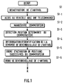
- FIG. 1 the flow diagram represents the sequence of operations carried out when the authorized user enters the vehicle, with the lock locked.
- FIG. 1 therefore describes the phase S1 known as deactivation of the anti-theft device.
- This phase mainly comprises a step S1-1 during which the user accesses the vehicle using a remote control.
- This remote control releases the locks which protect at least one opening of the vehicle, opening through which the user accesses the dashboard and the steering column. Following this operation, however, the anti-theft device is still locked.
- the dashboard is equipped with a switch of type substantially close to the well-known vehicle start switch. The user then operates an ignition key or an ignition ring in English-speaking countries.
- the ignition key is in fact, according to the method of the invention a false key in that it does not necessarily act on a mechanical lock, although such a real key brings an additional degree of security by adding a means locking or unlocking additional chain with the means of the invention.
- step S1-2 the user during a step S1-2 operates the start switch.
- the anti-theft device of the invention is connected to a central anti-theft device which then tests the position of the switch during a step S1-3.
- the anti-theft control unit has an analysis circuit capable of reading the position on which the start switch is placed.
- the start switch is, from the electrical point of view, constituted by at least one switch with several contacts, at least one contact being associated with a position of the start switch.
- the start switch contacts are notably connected to the input ports of a microcontroller such as an INTEL 8051.
- This circuit contains a program for reading the input ports to inform the anti-theft control unit of the position of the start switch.
- the movable finger of each switch of the start switch is connected to a suitable electrical voltage such as that established at the positive terminal of the vehicle battery.
- the voltage available on the contacts associated with the positions of the start switch is transmitted to the microcontroller of the anti-theft control unit via an interface circuit to adapt the signal to the port to which it is connected.
- the anti-theft control unit When the anti-theft control unit detects a position a of the start switch, it triggers a sequence of identification of the request to unlock the anti-theft device during a step S1-4.
- the anti-theft control unit produces an activation order admitting the decoding of the following positions of the start switch on electrical contacts b , c , and d during a step S1-5.
- the anti-theft control unit also successively or concurrently produces an order to unlock the steering column if the anti-theft device works by lock on the steering column, during a step S1-6.
- the central anti-theft system can issue other orders for unlocking like that of an injection computer, an ignition circuit, a battery switch, etc. ...
- This step S1-6 concludes the unlocking or deactivation phase of the anti-theft device, after which the vehicle can be started.
- step S2-1 the central anti-theft device detects an operation of the switch which consists in causing the latter to return to a position accepting the withdrawal of the key or false key.
- step S2-2 the anti-theft control unit activates the anti-theft means. Then, the successive positions a to d of the switch are deactivated. This completes the activation process for the lock.
- the anti-theft means of the invention comprises a key or false key 1, shown in the shape of a T, and which is intended to be introduced into the barrel or false barrel of a switch 2.
- the switch 2 is connected by an input from the anti-theft control unit 4 by via a link 3.
- the anti-theft control unit 4 exchanges signals with an interrogation and reception station 5 which exchanges 6.8 signals with a badge 7 for keyless access to the vehicle.
- the anti-theft control unit produces on a link 10 an order to activate an electromagnet 11, which has the function of enabling the anti-theft device to be activated or deactivated.
- the anti-theft control unit 4 produces an operating order for the motor 13 of the steering column anti-theft device or another vehicle security member.
- the anti-theft control unit 4 activates a forgetting alarm means 14.
- FIG 4 there is shown a developed diagram of the block diagram of Figure 3.
- the authorized key is here produced in the form of a badge.
- the anti-theft means 20 comprises a central unit 21 which is electrically connected to the switch 22.
- the switch 22 is, in one embodiment, surrounded by a means 23 for reading contactless writing and writing of the badge, like an antenna, for example the badge operating in a low radiated power mode so as to limit the risks of pirate listening.
- the antenna is connected to a read / write unit 24 which is itself connected by a bi-directional link 25 to the computer 21.
- the data content of the computer is, in one embodiment, saved by electricity accumulators 26 which allow its operation even when the vehicle battery is disconnected.
- the switch 22 mainly comprises a first two-position switch 27 which is operated by the insertion or removal of the key or dummy key (not shown in FIG. 4), and a second multi-position switch 28 which reproduces the positions d 'successive supply of various vehicle accessories and which are well known to those skilled in the art.
- the badge is installed in the head of the key.
- This has a rod or blade which may or may not have indentations or other means, mechanical or not, to serve as a lock.
- This has a barrel or slot through which the key or dummy key is inserted. The insertion or extraction of the key in the slot is detected by the first switch 27, the movable finger of which is operated by the key or dummy key.
- the key and the badge are two separate elements.
- the badge remains for example carried by the driver, in his pocket or on the wrist watch, or any other.
- the key can be mobile and can be inserted and extracted from the slot of the starter switch or can be almost fixed and can only be moved between two extreme positions in the slot.
- the first switch 27 comprises a tilting finger 29 permanently connected to the + BATT terminal of the vehicle battery and the other end of which is either connected in the position O 'when the key or dummy key is not engaged or else connected in position O when the key or dummy key is engaged.
- the contact O is connected to an input port 30 of the computer 21 which thus receives the information that the false key has been presented in the switch 22.
- the contact O ' is connected to the movable finger 31 of a switch M1 which is operated by the anti-theft device itself. Indeed, in the locked state of the lock, the switch M1 is placed on a VER contact which is not electrically connected, while in the unlocked state of the anti-theft device, the switch M1 is switched on a contact ENT which is connected to the power supply terminals positive supply circuit voltage 45 and 53 which will be described later.
- the contact ENT of the switch M1 is connected to a contact VER of a second switch M2 whose movable finger 32 is on the contact VER when the anti-theft device is in the locked state and on a contact ENT when it is in the 'unlocked state and which is permanently connected to a conductive area 33 of the second switch 28 of the switch 22.
- the second switch 28 of the switch 22 comprises a movable finger which is operated by the rotation of the dummy key when the latter turns in a conventional manner in the barrel or slot of the switch 22.
- the key or dummy key must be inserted into the aforementioned slot of the starter switch.
- the slot is formed in a member itself capable of rotating about an axis, in particular an axis parallel to the direction of insertion or extraction of the key.
- the movable finger of the second switch 28 is slaved to the aforementioned rotational movement.
- the movable finger 34 of the second switch 28 is, in the first position, connected to the conductive pad 33 and to a conductive pad 34.
- the conductive pad 34 is connected to an input port 36 of the central unit 21.
- the second switch 28 of the switch 22 then comprises conductive pads 37 and 38 and optionally to other additional conductive pads and which are connected to input ports 39 and 40 respectively of the microcontroller 21.
- the microcontroller 21 can be connected by a bus 41 to a central computer 42 for managing the electric power supply of the vehicle and which uses the position information of the first and second switches 27 and 28 of the switch 22 as well as the position sensors M1, M2, H1 and H2.
- the microcontroller 21 and the central computer 42 exchange their information according to a predetermined protocol on the bus 41 which is bi-directional.
- the microcontroller 21 has an output port 43 which is connected to the activation input 44 of a supply circuit 45 of the electromagnet 48 which makes it possible to activate the anti-theft means of the invention.
- the supply circuit 45 is constituted by a power amplifier which is supplied to the + BATT terminal of the vehicle battery by means of the first switch M1 when the latter is on its ENT contact, connected to the + BATT when the anti-theft means is in the unlocked state without breakdown.
- the microcontroller 21 also has two output ports 49 and 50, the first activated in the high state when the anti-theft means is in the locked state, the second 50 being activated in the high state when the anti-theft means is in the unlocked state.
- the ports 49 and 50 are respectively connected to inputs 51 and 52 of a bidirectional power supply circuit 53 supplying a motor 54 which mobilizes the movable bolt of the anti-theft lock (not shown).
- the movable bolt drives a magnetic element (not shown) which, in the locked position, is arranged near a first Hall effect sensor 55 when the anti-theft means is in the locked state and near a second sensor 56 Hall effect when the anti-theft means is in the unlocked state.
- the signals from the sensors 55 and 56 are transmitted to the input ports 57 and 58 respectively of the microcontroller 21 to inform the microcontroller of the locked or unlocked state of the swivel bolt of the steering column lock.
- FIG. 5 to 7 there is shown a front view, a side view in section and a top view of a switch according to the invention.
- the switch of the invention comprises a rotor 61, a stator 62, a switch 63 allowing electrical distribution to the vehicle, an electromagnet comprising a coil 64 and a plunger 65, a switch constituted by two flexible blades 66 and 66 ′ which can make contact.
- the switch With the vehicle at rest, the switch is in the stop position shown in FIGS. 5 to 7. To access the pipe, the user must push the rotor of the switch thanks to a gripping shape which is visible in FIGS. 6 and 9 on the rotor 61 in the form of a projection which projects outwards from the switch.
- This protruding shape constitutes a dummy key which remains permanently on the start switch and allows an insertion and withdrawal movement and a rotational movement after insertion, so as to simulate the action of a mechanical key and in order to produce a positive action which confirms the intention of the driver to lock or unlock the anti-theft device, as well as possibly that of leaving the vehicle after deactivating the anti-theft device.
- This embodiment has already been described partially above for the electrical structure part and will be detailed for the mechanical structure part.
- the key is removable and follows the driver. She can wear, in particular in her head, the transmitter badge of the keyless entry system. This other embodiment will not be described further.
- the lock of the invention cooperates with the keyless access system by means of the antenna integrated in the starter switch in particular.
- FIGS 8 to 10 therefore show the switch in the unlocked position.
- the microcontroller 21 If the user, wearing an authorized badge, is recognized by the microcontroller 21, the latter produces the anti-theft deactivation sequence.
- the detection means 55 and 56 (FIG. 4) send a signal to the microcontroller 21 which releases the plunger 65 from the electromagnet 64,65 of the switch Figures 6,9 and 12. The user can then rotate the false key 1 (or rotor) to access the vehicle start functions.
- the user turns the dummy key or rotor 61 in the opposite direction, then pulls the rotor 61.
- the blades 66 and 66 peel off, interrupting the electric current flowing through them, a situation which is recognized by the microcontroller 21 which then produces the column locking sequence.
- the locking member comprises two position sensors respectively 90 in Figure 13 and 91 in Figure 14, which are in the active state respectively when the locking member is in the unlocked state and when the the locking member is in the locked state.
- FIG 15 there is shown the housing containing the locking member according to the invention.
- the housing 92 of the locking member has fixing flanges 93 on a fixed part of the vehicle and a bore 94 through which the steering column passes (not shown).
- the housing 92 carries the electric motor 95 with its electrical terminals 96 and 97 as well as the end of the rotation shaft 98.
- the housing 92 also carries housings 99 and 100 constituting the Hall effect sensors previously described in Figures 4 (H1 and H2) and 13 and 14 (90.91).
- the housing 92 then carries the housings 101 and 102 of the switches M1 and M2 of FIG. 4 which make it possible to confirm the state of the locking member for the microcontroller 21.
- the housing 92 includes a housing 103 inside which is arranged an electromagnet for blocking the rotation of the cams.
- the effect of this electromagnet is whether or not to block the rotation of the steering column which is disposed between the locking cams 82, 83.
- FIG. 16 there is shown an exploded plan of the contents of the housing 92 of FIG. 15.
- the electric motor 95 drives via a pinion 110 a reducer consisting of pinions 111, 112 and 113.
- the pinion 113 is mounted on a rotation shaft 114 on which the cams 82 and 83 are mounted on either side.
- levers 79 and 80 of the pivoting bolts are also shown, as well as pins 115 and 116 which trap a spiral spring (not shown) which makes it possible to permanently push the levers 79 and 80 on the profile 84 or 85 of the cams 82 and 83 .
- the plunger core 117 of the electromagnet has also been shown, which, when its coil (not shown) is traversed by a current releases a blockage of the hollow rotation shaft 114.
Abstract
Description
Procédé de contrôle d'un organe antivol de véhicule avec système d'accès par commande à distance, et organe antivol ainsi constitué.Method for controlling a vehicle anti-theft device with remote control access system, and anti-theft device thus formed.
La présente invention concerne un procédé de contrôle d'un organe antivol de véhicule avec système d'accès par commande à distance. Elle concerne aussi un organe antivol ainsi constitué.The present invention relates to a method for controlling an anti-theft vehicle member with remote control access system. It also relates to an anti-theft device thus formed.
Dans l'état de la technique on a déjà proposé des dispositifs permettant de déverrouiller à distance et donc sans contact ni électrique ni mécanique les ouvrants d'un objet comme un véhicule. En particulier, on a développé des techniques d'accès sans clé (Keyless Entry System en anglais) qui permettent d'accéder à des ressources sans avoir à sortir une clé mécanique ou autrement d'autorisation de l'accès.In the state of the art, devices have already been proposed making it possible to unlock remotely and therefore without electrical or mechanical contact the openings of an object such as a vehicle. In particular, we have developed keyless entry techniques (Keyless Entry System in English) which allow access to resources without having to take out a mechanical key or otherwise authorize access.
Un tel système est très attractif par le confort qu'il apporte à l'usager et par les possibilités de gestion des accès par des moyens informatiques qu'il permet.Such a system is very attractive for the comfort it brings to the user and for the possibilities of managing access by computer means which it allows.
Dans l'application au verrouillage et au déverrouillage d'ouvrants comme ceux d'un véhicule, ou d'un antivol de sécurité comme celui d'une colonne de direction, ou de l'arbre de sortie de la boite de vitesses d'un véhicule, on a dans cette optique proposé des systèmes mécaniques utilisant des organes moteur de type électrique. Quand le système de gestion des accès reconnait le droit d'accès et une demande d'accès, un organe de commande produit un ordre d'actionnement qui excite l'organe moteur comme un électro-aimant ou un moteur électrique. L'antivol et/ou le verrou changent d'état en passant de l'état verrouillé à l'état déverrouillé.In the application to the locking and unlocking of doors such as those of a vehicle, or of a security lock such as that of a steering column, or of the output shaft of the gearbox of a vehicle, we have in this context proposed mechanical systems using electric type engine members. When the access management system recognizes the right of access and a request for access, a control member produces an actuation order which excites the motor member like an electromagnet or an electric motor. The anti-theft device and / or the lock change state from the locked state to the unlocked state.
Une séquence analogue inverse est produite pour la sortie ou l'activation de l'antivol.A reverse analog sequence is produced for the exit or activation of the anti-theft device.
Cependant, particulièrement dans l'application automobile, des situations dangereuses apparaissent à l'usage quand on utilise ce type de systèmes d'accès sans contact qui télécommande à la fois les ouvrants et l'antivol du véhicule. Par exemple, le dispositif d'identification ou télécommande peut être oublié par l'usager à l'intérieur du véhicule et de ce fait, l'activation de l'antivol et/ou du verrou des ouvrants n'est pas assuré.However, particularly in the automotive application, dangerous situations arise. use when using this type of contactless access systems which remote control both the windows and the vehicle anti-theft device. For example, the identification device or remote control can be forgotten by the user inside the vehicle and therefore the activation of the anti-theft device and / or of the opening lock is not ensured.
Pour remédier à l'oubli de la télécommande, qui prend la forme d'une clé ou d'une carte, on a proposé de détecter l'oubli de la télécommande par diverses techniques. Le résultat positif de cette détection produit une alarme qui est présumée attirer l'attention de l'usager oublieux.To remedy the forgetting of the remote control, which takes the form of a key or a card, it has been proposed to detect the forgetting of the remote control by various techniques. The positive result of this detection produces an alarm which is presumed to attract the attention of the forgetful user.
Mais ce type de dispositif complique notamment le système de contrôle d'accès et donc augmente son coût et réduit sa fiabilité et sa sécurité d'utilisation. De plus, il ne règle pas d'autres problèmes.However, this type of device notably complicates the access control system and therefore increases its cost and reduces its reliability and safety of use. In addition, it does not solve other problems.
En particulier, certains systèmes produisent des actions intempestives comme des verrouillages, par exemple si la télécommande a été oubliée au-delà d'un certain délai. Dans ce cas, l'usager perd la possibilité de pénétrer dans son véhicule.In particular, certain systems produce untimely actions such as locks, for example if the remote control has been forgotten after a certain time. In this case, the user loses the possibility of entering his vehicle.
Dans d'autres situations conduisant aussi à des actions intempestives, l'usager peut perdre temporairement sa télécommande alors que le véhicule est ouvert et parfois, plus encore, quand il est en train de rouler. Il s'ensuit que le système de gestion des accès ne trouve plus la présence de la télécommande. Notamment quand la télécommande travaille en mode transpondeur, dans lequel un module de bord interroge périodiquement la présence de la télécommande, des actions intempestives, ou même dangereuses pour le véhicule, peuvent être commandées par le système d'accès.In other situations also leading to untimely actions, the user may temporarily lose his remote control while the vehicle is open and sometimes, even more, when he is driving. It follows that the access management system no longer finds the presence of the remote control. In particular when the remote control works in transponder mode, in which an on-board module periodically interrogates the presence of the remote control, untimely actions, or even dangerous for the vehicle, can be controlled by the access system.
Enfin, particulièrement dans le domaine automobile, tant les habitudes des usagers que les normes nationales ou internationales en matière d'assurances contre le vol, ou de sécurité en matière de véhicules, conduisent à une difficulté d'adaptation des systèmes d'accès dit sans clé. Or, d'une manière générale, dans les systèmes d'accès sans clé, l'usager porteur d'une clé autorisée, comme une télécommande, accède directement au véhicule par l'action d'une centrale de contrôle d'accès. Dès que la centrale de contrôle d'accès détecte la présence de l'usager porteur de la clé autorisée, elle produit une action de déverrouillage des ouvrants du véhicule (portes, hayons, fenêtres, coffres, etc.) et de l'antivol (par exemple le verrou de colonne de direction). Il est clair donc que, notamment à cause des situations conduisant à des actions intempestives, les dispositifs actuellement proposés par les constructeurs ne permettent pas à la fois de respecter les usages acquis par l'habitude et les règlements de sécurité.Finally, particularly in the automotive field, both user habits and national or international insurance standards against theft, or vehicle security, lead to a difficulty in adapting the so-called keyless access systems. However, in general, in keyless access systems, the user carrying an authorized key, such as a remote control, directly accesses the vehicle by the action of an access control center. As soon as the access control center detects the presence of the user carrying the authorized key, it produces an unlocking action for the doors of the vehicle (doors, tailgate, windows, trunks, etc.) and the anti-theft device ( for example the steering column lock). It is therefore clear that, in particular because of the situations leading to untimely actions, the devices currently offered by the manufacturers do not make it possible at the same time to respect the uses acquired by habit and the safety regulations.
La présente invention permet notamment de résoudre les divers problèmes mentionnés plus haut.The present invention makes it possible in particular to solve the various problems mentioned above.
En effet, la présente invention concerne un procédé de contrôle d'un antivol de véhicule, ou d'un dispositif du même genre, avec système d'accès par commande à distance l'organe d'antivol comportant notamment un commutateur de commande de démarrage et d'alimentation électrique des accessoires du véhicule. Le procédé se caractérise par le fait que dans une phase de désactivation de l'antivol :
- on accède au véhicule avec une télécommande ;
- on manoeuvre un commutateur qui reproduit la manipulation des clés mécaniques habituelles ;
- on détecte une position déterminée du commutateur pour produire une interrogation d'identification de la demande de déverrouillage de l'antivol ;
- on produit en réponse un ordre d'activation de positions successives du commutateur et un ordre de déverrouillage de l'antivol ;
- on détecte une manoeuvre de désactivation de l'antivol sur le commutateur, ladite manoeuvre reproduisant les manipulations habituelles des clés mécaniques ;
- on active l'antivol ;
- on désactive les positions successives du commutateur.
- the vehicle is accessed with a remote control;
- a switch is operated which reproduces the manipulation of the usual mechanical keys;
- a determined position of the switch is detected to produce an interrogation identifying the request for unlocking the anti-theft device;
- an order to activate successive positions of the switch and an unlocking unlocking order are produced in response;
- an anti-theft deactivation maneuver is detected on the switch, said maneuver reproducing the usual manipulations of mechanical keys;
- the anti-theft device is activated;
- the successive positions of the switch are deactivated.
L'invention concerne aussi un organe d'antivol d'un objet comme un véhicule. L'antivol comporte :
- un module interrogateur-récepteur d'un badge comme un badge RF,
- un commutateur de démarrage et d'alimentation des accessoires du véhicule,
- un antivol motorisé,
- une centrale d'antivol connectée aux précédents éléments de façon à mettre en oeuvre le procédé de l'invention.
- an interrogator-receiver module of a badge such as an RF badge,
- a vehicle accessories start and power switch,
- a motorized lock,
- an anti-theft control unit connected to the preceding elements so as to implement the method of the invention.
D'autres caractéristiques et avantages de la présente invention seront mieux compris à l'aide de la description et des dessins qui sont :
- les figures 1 et 2 : deux organigrammes mettant en oeuvre le procédé de l'invention ;
- la figure 3 : un schéma de principe d'un mode de réalisation de l'invention ;
- la figure 4 : un schéma développé du mode de réalisation de la figure 3 ;
- les figures 5 à 7 : des vues d'un mode de réalisation du commutateur dans la position arrêt ;
- les figures 8 à 10 : des vues d'un mode de réalisation du commutateur dans la position déverrouillage ;
- les figures 11 et 12 : des vues d'un mode de réalisation du commutateur dans la position marche ;
- les figures 13 et 14 : des vues du moyen de verrouillage de la colonne de direction par un moteur électrique ;
- la figure 15 : une vue du boitier de raccordement électrique et mécanique de l'antivol selon l'invention ;
- la figure 16 : une vue en éclaté de l'antivol de la figure 15.
- Figures 1 and 2: two flowcharts implementing the method of the invention;
- Figure 3: a block diagram of an embodiment of the invention;
- Figure 4: a developed diagram of the embodiment of Figure 3;
- Figures 5 to 7: views of an embodiment of the switch in the off position;
- Figures 8 to 10: views of an embodiment of the switch in the unlocked position;
- Figures 11 and 12: views of an embodiment of the switch in the on position;
- Figures 13 and 14: views of the means of locking of the steering column by an electric motor;
- Figure 15: a view of the electrical and mechanical connection box of the lock according to the invention;
- Figure 16: an exploded view of the lock of Figure 15.
A la figure 1, l'organigramme représente la séquence des opérations effectuées quand l'utilisateur autorisé pénètre dans le véhicule, antivol verrouillé. La figure 1 décrit donc la phase S1 dite de désactivation de l'antivol. Cette phase comporte principalement une étape S1-1 pendant laquelle l'utilisateur accède au véhicule à l'aide d'une télécommande. Cette télécommande libère les verrous qui protègent au moins un ouvrant du véhicule, ouvrant par l'ouverture duquel l'utilisateur accède au tableau de bord et à la colonne de direction. A la suite de cette opération l'antivol est cependant toujours verrouillé.In FIG. 1, the flow diagram represents the sequence of operations carried out when the authorized user enters the vehicle, with the lock locked. FIG. 1 therefore describes the phase S1 known as deactivation of the anti-theft device. This phase mainly comprises a step S1-1 during which the user accesses the vehicle using a remote control. This remote control releases the locks which protect at least one opening of the vehicle, opening through which the user accesses the dashboard and the steering column. Following this operation, however, the anti-theft device is still locked.
Le tableau de bord est équipé d'un commutateur de type sensiblement proche du commutateur de démarrage du véhicule bien connu. L'utilisateur manoeuvre alors une clé de contact ou un anneau d'allumage ("ignition ring" dans les pays anglo-saxons).The dashboard is equipped with a switch of type substantially close to the well-known vehicle start switch. The user then operates an ignition key or an ignition ring in English-speaking countries.
La clé de contact est en fait, selon le procédé de l'invention une fausse clé en ce qu'elle n'agit pas nécessairement sur une serrure mécanique, bien qu'une telle clé réelle apporte un degré supplémentaire de sécurité en ajoutant un moyen de verrouillage ou de déverrouillage supplémentaire en chaine avec le moyen de l'invention.The ignition key is in fact, according to the method of the invention a false key in that it does not necessarily act on a mechanical lock, although such a real key brings an additional degree of security by adding a means locking or unlocking additional chain with the means of the invention.
Par cette clé, ou par tout autre moyen convenable, l'utilisateur au cours d'une étape S1-2 manoeuvre le commutateur de démarrage.By this key, or by any other suitable means, the user during a step S1-2 operates the start switch.
L'antivol de l'invention est connecté à une centrale d'antivol qui teste alors la position du commutateur lors d'une étape S1-3.The anti-theft device of the invention is connected to a central anti-theft device which then tests the position of the switch during a step S1-3.
La centrale d'antivol comporte un circuit d'analyse capable de lire la position sur laquelle est placé le commutateur de démarrage. Le commutateur de démarrage est, au point de vue électrique, constitué par au moins un interrupteur à plusieurs contacts, un contact au moins étant associé à une position du commutateur de démarrage. Les contacts du commutateur de démarrage sont notamment reliés à des ports d'entrée d'un microcontrôleur comme un circuit INTEL 8051. Ce dernier contient un programme de lecture des ports d'entrée pour informer la centrale antivol de la position du commutateur de démarrage. A cette fin, le doigt mobile de chaque interrupteur du commutateur de démarrage est connecté à une tension électrique convenable comme celle établie à la borne positive de la batterie du véhicule.The anti-theft control unit has an analysis circuit capable of reading the position on which the start switch is placed. The start switch is, from the electrical point of view, constituted by at least one switch with several contacts, at least one contact being associated with a position of the start switch. The start switch contacts are notably connected to the input ports of a microcontroller such as an INTEL 8051. This circuit contains a program for reading the input ports to inform the anti-theft control unit of the position of the start switch. To this end, the movable finger of each switch of the start switch is connected to a suitable electrical voltage such as that established at the positive terminal of the vehicle battery.
Dans d'autres modes de réalisation, la tension disponible sur les contacts associés aux positions du commutateur de démarrage est transmise au microcontrôleur de la centrale antivol par l'intermédiaire d'un circuit d'interfaçage pour adapter le signal au port auquel il est relié.In other embodiments, the voltage available on the contacts associated with the positions of the start switch is transmitted to the microcontroller of the anti-theft control unit via an interface circuit to adapt the signal to the port to which it is connected. .
Quand la centrale d'antivol détecte une position a du commutateur de démarrage, elle déclenche une séquence d'identification de la demande de déverrouillage de l'antivol lors d'une étape S1-4.When the anti-theft control unit detects a position a of the start switch, it triggers a sequence of identification of the request to unlock the anti-theft device during a step S1-4.
Si l'utilisateur est reconnu, la centrale antivol produit un ordre d'activation admettant le décodage de positions suivantes du commutateur de démarrage sur des contacts électriques b, c, et d lors d'une étape S1-5.If the user is recognized, the anti-theft control unit produces an activation order admitting the decoding of the following positions of the start switch on electrical contacts b , c , and d during a step S1-5.
La centrale antivol produit aussi successivement ou concurremment un ordre de déverrouillage de la colonne de direction si l'antivol travaille par verrou sur la colonne de direction, lors d'une étape S1-6.The anti-theft control unit also successively or concurrently produces an order to unlock the steering column if the anti-theft device works by lock on the steering column, during a step S1-6.
En fonction de la nature de l'antivol, la centrale d'antivol peut émettre d'autres ordres de déverrouillage comme celui d'un calculateur d'injection, d'un circuit d'allumage, d'un commutateur de batterie, etc. ... .Depending on the nature of the anti-theft system, the central anti-theft system can issue other orders for unlocking like that of an injection computer, an ignition circuit, a battery switch, etc. ...
Si l'utilisateur n'est pas reconnu, une étape non représentée à la figure 1 permet :
- ou bien de reprendre une procédure de désactivation de l'antivol depuis le début, le nombre de reprises pouvant être limité (à trois par exemple) ;
- ou bien de bloquer la procédure de désactivation et éventuellement de produire une alarme ou une inscription en mémoire des circonstances du refus de désactivation, notamment si la reprise de la procédure de désactivation a été déjà effectuée un nombre prédéterminé de fois (3 dans un exemple préféré).
- or to resume a procedure to deactivate the anti-theft device from the start, the number of times being able to be limited (to three for example);
- or block the deactivation procedure and possibly produce an alarm or a recording in memory of the circumstances of the deactivation refusal, in particular if the resumption of the deactivation procedure has already been carried out a predetermined number of times (3 in a preferred example ).
Cette étape S1-6 conclut la phase de déverrouillage ou de désactivation de l'antivol, à la suite de laquelle le véhicule peut être mis en route.This step S1-6 concludes the unlocking or deactivation phase of the anti-theft device, after which the vehicle can be started.
A la Figure 2, on a représentée une phase S2 dite d'activation ou de verrouillage de la colonne, qui par inversion des étapes précédentes, permet de revenir à un état d'antivol actif.In Figure 2, there is shown a phase S2 called activation or locking of the column, which by reversing the previous steps, allows to return to an active anti-theft state.
Lors de l'étape S2-1, la centrale d'antivol détecte une manoeuvre du commutateur qui consiste à faire revenir ce dernier vers une position acceptant le retrait de la clé ou fausse clé.During step S2-1, the central anti-theft device detects an operation of the switch which consists in causing the latter to return to a position accepting the withdrawal of the key or false key.
Lors de l'étape S2-2, la centrale d'antivol active le moyen d'antivol. Puis, on désactive les positions successives a à d du commutateur. On termine ainsi le processus d'activation de l'antivol.During step S2-2, the anti-theft control unit activates the anti-theft means. Then, the successive positions a to d of the switch are deactivated. This completes the activation process for the lock.
A la figure 3, on a représenté un schéma de principe d'un mode de réalisation de l'invention.In Figure 3, there is shown a block diagram of an embodiment of the invention.
A la figure 3, le moyen d'antivol de l'invention comporte une clé ou fausse clé 1, représentée en forme de T, et qui est destinée à venir s'introduire dans le canon ou faux canon d'un commutateur 2. Le commutateur 2 est connecté par une entrée de la centrale antivol 4 par l'intermédiaire d'une liaison 3. Par une autre entrée, la centrale antivol 4 échange des signaux avec une station d'interrogation et de réception 5 qui échange 6,8 des signaux avec un badge 7 d'accès sans clé au véhicule. En fonction des échanges qui seront décrits plus loin, la centrale antivol produit sur une liaison 10 un ordre d'activation d'un électro-aimant 11, qui a pour fonction de permettre l'activation ou la désactivation de l'antivol.In FIG. 3, the anti-theft means of the invention comprises a key or
D'autre part, par une liaison 12, la centrale d'antivol 4 produit un ordre de fonctionnement du moteur 13 de l'antivol de colonne de direction ou d'un autre organe de sécurité du véhicule.On the other hand, by a link 12, the anti-theft control unit 4 produces an operating order for the
D'autre part, si l'utilisateur du véhicule oublie le badge radiofréquence à l'intérieur du véhicule ou s'il omet de manoeuvrer la clé 1 pour entrer dans la séquence d'activation S2 de l'antivol alors qu'il laisse son badge 7 dans le véhicule, la centrale antivol 4 produit l'activation d'un moyen d'alarme d'oubli 14.On the other hand, if the user of the vehicle forgets the radio frequency badge inside the vehicle or if he fails to operate the key 1 to enter the activation sequence S2 of the anti-theft device while he leaves his badge 7 in the vehicle, the anti-theft control unit 4 activates a forgetting alarm means 14.
A la figure 4, on a représenté un schéma développé du schéma de principe de la figure 3. La clé autorisée est ici réalisée sous la forme d'un badge.In Figure 4, there is shown a developed diagram of the block diagram of Figure 3. The authorized key is here produced in the form of a badge.
Le moyen d'antivol 20 comporte une unité centrale 21 qui est connectée de manière électrique au commutateur 22. D'autre part, le commutateur 22 est, dans un mode de réalisation, entouré par un moyen 23 de lecture écriture sans contact du badge, comme une antenne, par exemple le badge fonctionnant dans un mode en faible puissance rayonnée de façon à limiter les risques d'écoute pirate.The anti-theft means 20 comprises a central unit 21 which is electrically connected to the
L'antenne est connectée à une unité de lecture écriture 24 qui est elle-même connectée par une liaison bi-directionnelle 25 au calculateur 21. Le contenu en données du calculateur est, dans un mode de réalisation, sauvegardé par des accumulateurs d'électricité 26 qui permettent son fonctionnement même quand la batterie du véhicule est déconnectée.The antenna is connected to a read /
Le commutateur 22 comporte principalement un premier interrupteur à deux positions 27 qui est manoeuvré par l'introduction ou le retrait de la clé ou fausse clé (non représentée à la figure 4), et un second interrupteur 28 à plusieurs positions qui reproduisent les positions d'alimentation successives des divers accessoires du véhicule et qui sont bien connus de l'homme de métier.The
Dans un mode de réalisation, le badge est installé dans la tête de la clé. Celle-ci présente une tige ou lame qui peut ou non présenter des indentations ou d'autres moyens, mécaniques ou non, pour servir à un verrou. Celui-ci présente un canon ou fente à travers laquelle est introduite la clé ou fausse clé. L'insertion ou l'extraction de la clé dans la fente est détectée par le premier interrupteur 27 dont le doigt mobile est manoeuvré par la clé ou fausse clé.In one embodiment, the badge is installed in the head of the key. This has a rod or blade which may or may not have indentations or other means, mechanical or not, to serve as a lock. This has a barrel or slot through which the key or dummy key is inserted. The insertion or extraction of the key in the slot is detected by the
Dans un autre mode de réalisation, la clé et le badge sont deux éléments distincts. Le badge reste par exemple porté par le conducteur, dans sa poche ou sur la montre de poignet, ou tout autre. La clé peut être mobile et être insérée et extraite de la fente du commutateur de démarrage ou peut être quasi fixe et être seulement mobile entre deux positions extrêmes dans la fente.In another embodiment, the key and the badge are two separate elements. The badge remains for example carried by the driver, in his pocket or on the wrist watch, or any other. The key can be mobile and can be inserted and extracted from the slot of the starter switch or can be almost fixed and can only be moved between two extreme positions in the slot.
Le premier interrupteur 27 comporte un doigt basculant 29 relié en permanence à la borne +BATT de la batterie du véhicule et dont l'autre extrémité est ou bien connectée dans la position O' quand la clé ou fausse clé n'est pas engagée ou bien connectée dans la position O quand la clé ou fausse clé est engagée.The
Le contact O est connecté à un port d'entrée 30 du calculateur 21 qui reçoit ainsi l'information que la fausse clé a été présentée dans le commutateur 22.The contact O is connected to an
Le contact O' est connecté au doigt mobile 31 d'un interrupteur M1 qui est manoeuvré par l'antivol luimême. En effet, dans l'état verrouillé de l'antivol, l'interrupteur M1 est placé sur un contact VER qui n'est pas connecté électriquement, tandis que dans l'état déverrouillé de l'antivol, l'interrupteur M1 est basculé sur un contact ENT qui est connecté sur les bornes d'alimentation en tension positive de circuit d'alimentation 45 et 53 qui seront décrits plus loin.The contact O 'is connected to the
Le contact ENT de l'interrupteur M1 est connecté à un contact VER d'un second interrupteur M2 dont le doigt mobile 32 est sur le contact VER quand l'antivol est dans l'état verrouillé et sur un contact ENT quand il est dans l'état déverrouillé et qui est connecté en permanence à une zone 33 conductrice du second interrupteur 28 du commutateur 22.The contact ENT of the switch M1 is connected to a contact VER of a second switch M2 whose
Le second interrupteur 28 du commutateur 22 comporte un doigt mobile qui est manoeuvré par la rotation de la fausse clé quand celle-ci tourne de manière classique dans le canon ou fente du commutateur 22.The
Pour admettre le mouvement de rotation, la clé ou fausse clé doit être insérée dans la fente précitée du commutateur de démarrage. Dans un mode de réalisation, la fente est constituée dans un organe lui-même susceptible de tourner autour d'un axe, notamment d'un axe parallèle à la direction d'insertion ou d'extraction de la clé. Le doigt mobile du second interrupteur 28 est asservi au mouvement de rotation précité. Le doigt mobile 34 du second interrupteur 28 est, dans la première position, connecté sur la plage conductrice 33 et sur une plage conductrice 34. La plage conductrice 34 est connectée à un port d'entrée 36 de l'unité centrale 21.To allow the rotary movement, the key or dummy key must be inserted into the aforementioned slot of the starter switch. In one embodiment, the slot is formed in a member itself capable of rotating about an axis, in particular an axis parallel to the direction of insertion or extraction of the key. The movable finger of the
Le second interrupteur 28 du commutateur 22 comporte ensuite des plages conductrices 37 et 38 et éventuellement à d'autres plages conductrices supplémentaires et qui sont connectées à des ports d'entrée respectivement 39 et 40 du microcontrôleur 21. Le microcontrôleur 21 peut être connecté par un bus 41 à un ordinateur central 42 de gestion de l'alimentation électrique du véhicule et qui exploite l'information de position des premier et second interrupteurs 27 et 28 du commutateur 22 ainsi que des capteurs de position M1, M2, H1 et H2.The
Le microcontrôleur 21 et l'ordinateur central 42 échangent leurs informations selon un protocole prédéterminé sur le bus 41 qui est bi-directionnel.The microcontroller 21 and the
Le microcontrôleur 21 comporte un port de sortie 43 qui est connecté à l'entrée d'activation 44 d'un circuit d'alimentation 45 de l'électro-aimant 48 qui permet d'activer le moyen antivol de l'invention. Le circuit d'alimentation 45 est constitué par un amplificateur de puissance qui est alimenté à la borne +BATT de la batterie du véhicule par l'intermédiaire du premier interrupteur M1 quand celui-ci est sur son contact ENT, connecté au +BATT quand le moyen antivol est dans l'état déverrouillé sans panne.The microcontroller 21 has an
Le microcontrôleur 21 comporte aussi deux ports de sortie 49 et 50, le premier activé à l'état haut quand le moyen antivol est dans l'état verrouillé, le second 50 étant activé à l'état haut quand le moyen antivol est dans l'état déverrouillé.The microcontroller 21 also has two
Les ports 49 et 50 sont respectivement connectés à des entrées 51 et 52 d'un circuit d'alimentation 53 bidirectionnel en courant d'alimentation d'un moteur 54 qui mobilise le pêne mobile du verrou d'antivol (non représenté). Le pêne mobile entraîne un élément magnétique (non représenté) qui, dans la position verrouillée, est disposé à proximité d'un premier capteur 55 à effet Hall quand le moyen antivol est dans l'état verrouillé et à proximité d'un second capteur 56 à effet Hall quand le moyen antivol est dans l'état déverrouillé. Les signaux issus des capteurs 55 et 56 sont transmis à des ports d'entrée respectivement 57 et 58 du microcontrôleur 21 pour informer le microcontrôleur de l'état verrouillé ou déverrouillé du pêne pivotant de l'antivol de colonne de direction.The
Aux figures 5 à 7, on a représenté une vue de face, une vue de côté en coupe et une vue de dessus d'un commutateur selon l'invention.Figures 5 to 7, there is shown a front view, a side view in section and a top view of a switch according to the invention.
Le commutateur de l'invention comporte un rotor 61, un stator 62, un interrupteur 63 permettant la distribution électrique au véhicule, un électro-aimant comprenant une bobine 64 et un plongeur 65, un interrupteur constitué par deux lames souples 66 et 66' pouvant faire contact.The switch of the invention comprises a
Véhicule au repos, le commutateur est dans la position arrêt représentée aux figures 5 à 7. Pour accéder à la conduite, l'utilisateur doit pousser le rotor du commutateur grâce à une forme préhensible qui est visible aux figures 6 et 9 sur le rotor 61 sous la forme d'une avancée qui fait saillie vers l'extérieur du commutateur. Cette forme en saillie constitue une fausse clé qui reste à demeure sur le commutateur de démarrage et permet un mouvement d'insertion puis de retrait et un mouvement de rotation après l'insertion, de façon à simuler l'action d'une clé mécanique et afin de produire une action positive qui confirme l'intention du conducteur de verrouiller ou de déverrouiller l'antivol, ainsi éventuellement que celle de quitter le véhicule après désactivation de l'antivol. Ce mode de réalisation a déjà été décrit plus haut partiellement pour la partie de structure électrique et va être détaillé pour la partie de structure mécanique.With the vehicle at rest, the switch is in the stop position shown in FIGS. 5 to 7. To access the pipe, the user must push the rotor of the switch thanks to a gripping shape which is visible in FIGS. 6 and 9 on the
Dans un autre mode de réalisation, la clé est amovible et suit le conducteur. Elle peut porter, notamment dans sa tête, le badge émetteur du système d'entrée sans clé. Cet autre mode de réalisation ne sera pas plus décrit.In another embodiment, the key is removable and follows the driver. She can wear, in particular in her head, the transmitter badge of the keyless entry system. This other embodiment will not be described further.
On constate ici que l'antivol de l'invention coopère avec le système d'accès sans clé par le moyen de l'antenne intégrée au commutateur de démarrage notamment.It can be seen here that the lock of the invention cooperates with the keyless access system by means of the antenna integrated in the starter switch in particular.
On va maintenant décrire le mode de réalisation mécanique dans lequel une forme fait saillie pour permettre sa préhension par l'usager sur la commutateur de démarrage.We will now describe the mechanical embodiment in which a shape projects to allow it to be grasped by the user on the start switch.
Quand le rotor 61 est enfoncé à fond, il est en position de déverrouillage, ce qui produit la mise en contact entre les lames 66 et 66' d'une part et le rotor 61 vient sur l'interrupteur 63 d'autre part. On remarque que l'interrupteur 63 et les lames 66 et 66' correspondent respectivement au second interrupteur 28 et au premier interrupteur 27 du commutateur 22 du mode de réalisation de la figure 4.When the
Les figures 8 à 10 représentent donc le commutateur dans la position de déverrouillage.Figures 8 to 10 therefore show the switch in the unlocked position.
Si l'utilisateur, porteur d'un badge autorisé, est reconnu par le microcontrôleur 21, ce dernier produit la séquence de désactivation de l'antivol. Lors du démarrage du véhicule, l'utilisateur enfonce la fausse clé ou rotor 61, les moyens de détection 55 et 56 (figure 4) envoient un signal au microcontrôleur 21 qui libère le plongeur 65 de l'électro-aimant 64,65 du commutateur des figures 6,9 et 12. L'utilisateur peut alors faire tourner la fausse clé 1 (ou rotor) pour accéder aux fonctions de démarrage du véhicule.If the user, wearing an authorized badge, is recognized by the microcontroller 21, the latter produces the anti-theft deactivation sequence. When starting the vehicle, the user pushes the false key or
A l'inverse, pour quitter le véhicule, l'utilisateur tourne la fausse clé ou rotor 61 en sens inverse, puis tire le rotor 61. Les lames 66 et 66' se décollent, interrompant le courant électrique qui les traversent, situation qui est reconnue par le microcontrôleur 21 qui produit alors la séquence de verrouillage de colonne.Conversely, to leave the vehicle, the user turns the dummy key or
Aux figures 13 et 14, on a représenté un mode de réalisation de l'organe de verrouillage de la colonne de direction équipé de pênes pivotants.In Figures 13 and 14, there is shown an embodiment of the locking member of the steering column equipped with pivoting bolts.
L'organe de verrouillage à la figure 13 comporte une bride de fixation 70 sur laquelle sont montés des pênes pivotants 71 et 72. La colonne de direction 73 est munie d'une partie dentée 74, l'espace entre deux dents successives étant destiné à recevoir l'extrémité 75 du pêne 71 et 76 du pêne 72. Les pênes pivotants sont montés sur des articulations 77 et 78 et comportent des leviers 79 et 80 qui sont mobilisés par un organe moteur 81. L'organe moteur comporte un moteur électrique commandé par le microcontrôleur 21 de la figure 3, dont l'arbre de rotation entraîne des cames 82 et 83 en rotation. Les cames 82 et 83 sont en contact avec l'extrémité libre des leviers 79 et 80 de façon à :
- dans l'état verrouillé de l'organe de verrouillage (figure 13) bloquer les pênes pivotants en engagement sur le secteur denté 74 de la colonne 73 ;
- dans l'état déverrouillé de l'organe de verrouillage (figure 14) à repousser les pênes pivotants 71
et 72 hors de lazone dentée 74 de façon à libérer la colonne de direction.
- in the locked state of the locking member (Figure 13) block the pivoting bolts in engagement on the
toothed sector 74 of thecolumn 73; - in the unlocked state of the locking member (Figure 14) to push the pivoting
bolts toothed area 74 so as to release the steering column.
A la figure 14, les profils sont visibles sous la référence 84 pour la came 82 et 85 pour la came 83.In FIG. 14, the profiles are visible under the
D'autre part l'organe de verrouillage comporte deux capteurs de position respectivement 90 à la figure 13 et 91 à la figure 14, qui sont à l'état actif respectivement quand l'organe de verrouillage est dans l'état déverrouillé et quand l'organe de verrouillage est dans l'état verrouillé.On the other hand the locking member comprises two position sensors respectively 90 in Figure 13 and 91 in Figure 14, which are in the active state respectively when the locking member is in the unlocked state and when the the locking member is in the locked state.
A la figure 15, on a représenté le boîtier contenant l'organe de verrouillage selon l'invention. Le boitier 92 de l'organe de verrouillage comporte des brides de fixation 93 sur une partie fixe du véhicule et un alésage 94 à travers lequel passe la colonne de direction (non représentée). Le boîtier 92 porte le moteur électrique 95 avec ses bornes électriques 96 et 97 ainsi que le bout d'arbre de rotation 98. Le boîtier 92 porte aussi des boîtiers 99 et 100 constituant les capteurs à effet Hall décrits précédemment aux figures 4 (H1 et H2) et 13 et 14 (90,91).In Figure 15, there is shown the housing containing the locking member according to the invention. The
Le boîtier 92 porte ensuite les boîtiers 101 et 102 des interrupteurs M1 et M2 de la figure 4 qui permettent de confirmer l'état de l'organe de verrouillage pour le microcontrôleur 21.The
Enfin le boîtier 92 comporte un logement 103 à l'intérieur duquel est disposé un électro-aimant de blocage en rotation des cames. L'effet de cet électro-aimant est de bloquer ou non la rotation de la colonne de direction qui est disposée entre les cames de blocage 82, 83.Finally, the
A la figure 16 on a représenté un plan en éclaté du contenu du boîtier 92 de la figure 15. Le moteur électrique 95 entraîne par l'intermédiaire d'un pignon 110 un réducteur constitué de pignons 111,112 et 113. Le pignon 113 est monté sur un arbre de rotation 114 sur lequel sont montées de part et d'autre les cames 82 et 83.In FIG. 16 there is shown an exploded plan of the contents of the
On a représenté aussi les leviers 79 et 80 des pênes pivotants ainsi que des tétons 115 et 116 qui emprisonnent un ressort spiral (non représenté) qui permet de repousser en permanence les leviers 79 et 80 sur le profil 84 ou 85 des cames 82 et 83.The
On a aussi représenté le noyau plongeur 117 de l'électro-aimant, qui, quand sa bobine (non représentée) est parcourue par un courant relâche un blocage de l'arbre de rotation creux 114.The
On a aussi représenté un doigt 118 destiné à venir manoeuvrer l'armature mobile des interrupteurs 101 et 102 qui réalisent les interrupteurs M1 et M2 de la figure 4.There is also shown a
Claims (14)
Applications Claiming Priority (2)
| Application Number | Priority Date | Filing Date | Title |
|---|---|---|---|
| FR9311671A FR2710599B1 (en) | 1993-09-30 | 1993-09-30 | Method for controlling a vehicle anti-theft device with remote control access system, and anti-theft device thus formed. |
| FR9311671 | 1993-09-30 |
Publications (2)
| Publication Number | Publication Date |
|---|---|
| EP0646506A1 true EP0646506A1 (en) | 1995-04-05 |
| EP0646506B1 EP0646506B1 (en) | 1998-11-25 |
Family
ID=9451425
Family Applications (1)
| Application Number | Title | Priority Date | Filing Date |
|---|---|---|---|
| EP19940114576 Expired - Lifetime EP0646506B1 (en) | 1993-09-30 | 1994-09-16 | Anti-theft control procedure and device therefor, for vehicles with remote control access systems |
Country Status (4)
| Country | Link |
|---|---|
| EP (1) | EP0646506B1 (en) |
| DE (1) | DE69414807T2 (en) |
| ES (1) | ES2125388T3 (en) |
| FR (1) | FR2710599B1 (en) |
Cited By (2)
| Publication number | Priority date | Publication date | Assignee | Title |
|---|---|---|---|---|
| WO1996020854A1 (en) * | 1994-12-30 | 1996-07-11 | Marquardt Gmbh | Switching device for locking systems |
| EP0761515A1 (en) * | 1995-09-12 | 1997-03-12 | Valeo Securite Habitacle | Electrical anti-theft system for a motor vehicle |
Families Citing this family (2)
| Publication number | Priority date | Publication date | Assignee | Title |
|---|---|---|---|---|
| FR2731965B1 (en) * | 1995-03-21 | 1997-04-25 | Valeo Securite Habitacle | ELECTRICAL THEFT |
| FR2731968B1 (en) * | 1995-03-21 | 1997-04-30 | Valeo Securite Habitacle | ELECTRICAL THEFT, ESPECIALLY FOR A MOTOR VEHICLE |
Citations (4)
| Publication number | Priority date | Publication date | Assignee | Title |
|---|---|---|---|---|
| US4719460A (en) * | 1983-09-19 | 1988-01-12 | Nissan Motor Company, Limited | Keyless entry system for automotive vehicle devices with theft-prevention feature |
| WO1993004899A1 (en) * | 1991-08-28 | 1993-03-18 | Prj Corporation | Passive vehicular theft deterrent system and method |
| GB2261992A (en) * | 1991-11-29 | 1993-06-02 | Keith Nunnerley Aitchison | An anti-theft device for a motor vehicle |
| DE4240426A1 (en) * | 1992-12-02 | 1994-06-09 | Thomas Schmitz | Ignition key protection system for centralised locking of motor vehicle - uses interrogation signal and detected response to unlock locked vehicle when ignition key is still inside |
-
1993
- 1993-09-30 FR FR9311671A patent/FR2710599B1/en not_active Expired - Lifetime
-
1994
- 1994-09-16 DE DE1994614807 patent/DE69414807T2/en not_active Expired - Lifetime
- 1994-09-16 EP EP19940114576 patent/EP0646506B1/en not_active Expired - Lifetime
- 1994-09-16 ES ES94114576T patent/ES2125388T3/en not_active Expired - Lifetime
Patent Citations (4)
| Publication number | Priority date | Publication date | Assignee | Title |
|---|---|---|---|---|
| US4719460A (en) * | 1983-09-19 | 1988-01-12 | Nissan Motor Company, Limited | Keyless entry system for automotive vehicle devices with theft-prevention feature |
| WO1993004899A1 (en) * | 1991-08-28 | 1993-03-18 | Prj Corporation | Passive vehicular theft deterrent system and method |
| GB2261992A (en) * | 1991-11-29 | 1993-06-02 | Keith Nunnerley Aitchison | An anti-theft device for a motor vehicle |
| DE4240426A1 (en) * | 1992-12-02 | 1994-06-09 | Thomas Schmitz | Ignition key protection system for centralised locking of motor vehicle - uses interrogation signal and detected response to unlock locked vehicle when ignition key is still inside |
Cited By (4)
| Publication number | Priority date | Publication date | Assignee | Title |
|---|---|---|---|---|
| WO1996020854A1 (en) * | 1994-12-30 | 1996-07-11 | Marquardt Gmbh | Switching device for locking systems |
| EP0761515A1 (en) * | 1995-09-12 | 1997-03-12 | Valeo Securite Habitacle | Electrical anti-theft system for a motor vehicle |
| FR2738542A1 (en) * | 1995-09-12 | 1997-03-14 | Valeo Securite Habitacle | ELECTRIC ANTI-THEFT SYSTEM, FOR A MOTOR VEHICLE |
| US5811887A (en) * | 1995-09-12 | 1998-09-22 | Valeo Securite Habitacle | Electrical antitheft system for motor vehicle |
Also Published As
| Publication number | Publication date |
|---|---|
| FR2710599B1 (en) | 1995-11-24 |
| EP0646506B1 (en) | 1998-11-25 |
| DE69414807D1 (en) | 1999-01-07 |
| DE69414807T2 (en) | 1999-04-22 |
| ES2125388T3 (en) | 1999-03-01 |
| FR2710599A1 (en) | 1995-04-07 |
Similar Documents
| Publication | Publication Date | Title |
|---|---|---|
| FR2740414A1 (en) | COMMUNICATION SYSTEM PROVIDED BETWEEN A CONTACT KEY AND A VEHICLE AND PROTECTS AGAINST FALSE MANEUVER | |
| EP0733521B1 (en) | Electric anti-theft device | |
| EP0596805B1 (en) | Remote control system for locking and unlocking doors and opening parts of a motor vehicle | |
| EP1335330B1 (en) | System for unlocking a motor vehicle opening | |
| FR2663074A1 (en) | REMOTE CONTROL SYSTEM FOR CLOSURES. | |
| FR2589186A1 (en) | LOCKING AND UNLOCKING SYSTEM FOR CAR CONTROL BY RADIO SIGNAL | |
| EP1581414B1 (en) | Vehicle anti-theft system and method, and use thereof for managing a fleet of vehicles | |
| FR2716147A1 (en) | Vehicle security system. | |
| EP1926060A2 (en) | Device and method for locking self-service vehicles | |
| FR2868459A1 (en) | Panel/drawer locking device for showcase door, has electronic module to trigger time interval and to signal imminence of triggering of alarm device when finger`s presence is not detected so that user closes panel or reads electronic medium | |
| EP0646506B1 (en) | Anti-theft control procedure and device therefor, for vehicles with remote control access systems | |
| EP0733524B1 (en) | Electric anti-theft device, especially for a motor vehicle | |
| WO2011073271A1 (en) | Device for activating a hands-free system | |
| EP0733526B1 (en) | Improved electric anti-theft device, especially for a motor vehicle | |
| FR2989650A1 (en) | Secure case for storing components used in operation of e.g. car, has lid for closing of case, and locking unit locking lid in closed position on case and adapted to unlock of opening of rental or use of car | |
| EP1122809A1 (en) | Antennas placed in strap handles for hands-free remote entry system | |
| FR2783222A1 (en) | Starting and security assembly for motor vehicle, includes system to start and stop vehicle engine using bistable button formed in key support | |
| EP0733522B1 (en) | Electric anti-theft device for a motor vehicle | |
| EP0596762B1 (en) | Theft preventing device on the steering mechanism for vehicle and key for such device | |
| EP1099813B1 (en) | Hand-free access system for a motor vehicle equipped with warning means | |
| WO2002068781A1 (en) | Device for actuating a lock | |
| FR2759960A1 (en) | Anti-theft protection mechanism for cars | |
| EP0733525B1 (en) | Improved electric anti-theft device, especially for a motor vehicle | |
| EP0769434A1 (en) | Steering locking apparatus | |
| FR2764927A1 (en) | Device for locking and unlocking vehicle doors from distance |
Legal Events
| Date | Code | Title | Description |
|---|---|---|---|
| PUAI | Public reference made under article 153(3) epc to a published international application that has entered the european phase |
Free format text: ORIGINAL CODE: 0009012 |
|
| AK | Designated contracting states |
Kind code of ref document: A1 Designated state(s): DE ES GB IT |
|
| 17P | Request for examination filed |
Effective date: 19950925 |
|
| 17Q | First examination report despatched |
Effective date: 19961115 |
|
| GRAG | Despatch of communication of intention to grant |
Free format text: ORIGINAL CODE: EPIDOS AGRA |
|
| GRAG | Despatch of communication of intention to grant |
Free format text: ORIGINAL CODE: EPIDOS AGRA |
|
| GRAH | Despatch of communication of intention to grant a patent |
Free format text: ORIGINAL CODE: EPIDOS IGRA |
|
| GRAH | Despatch of communication of intention to grant a patent |
Free format text: ORIGINAL CODE: EPIDOS IGRA |
|
| GRAA | (expected) grant |
Free format text: ORIGINAL CODE: 0009210 |
|
| AK | Designated contracting states |
Kind code of ref document: B1 Designated state(s): DE ES GB IT |
|
| GBT | Gb: translation of ep patent filed (gb section 77(6)(a)/1977) |
Effective date: 19981126 |
|
| REF | Corresponds to: |
Ref document number: 69414807 Country of ref document: DE Date of ref document: 19990107 |
|
| REG | Reference to a national code |
Ref country code: ES Ref legal event code: FG2A Ref document number: 2125388 Country of ref document: ES Kind code of ref document: T3 |
|
| PLBE | No opposition filed within time limit |
Free format text: ORIGINAL CODE: 0009261 |
|
| STAA | Information on the status of an ep patent application or granted ep patent |
Free format text: STATUS: NO OPPOSITION FILED WITHIN TIME LIMIT |
|
| 26N | No opposition filed | ||
| REG | Reference to a national code |
Ref country code: GB Ref legal event code: IF02 |
|
| PGFP | Annual fee paid to national office [announced via postgrant information from national office to epo] |
Ref country code: DE Payment date: 20130910 Year of fee payment: 20 Ref country code: ES Payment date: 20130920 Year of fee payment: 20 |
|
| PGFP | Annual fee paid to national office [announced via postgrant information from national office to epo] |
Ref country code: GB Payment date: 20130920 Year of fee payment: 20 |
|
| PGFP | Annual fee paid to national office [announced via postgrant information from national office to epo] |
Ref country code: IT Payment date: 20130923 Year of fee payment: 20 |
|
| REG | Reference to a national code |
Ref country code: DE Ref legal event code: R071 Ref document number: 69414807 Country of ref document: DE |
|
| REG | Reference to a national code |
Ref country code: DE Ref legal event code: R071 Ref document number: 69414807 Country of ref document: DE |
|
| REG | Reference to a national code |
Ref country code: GB Ref legal event code: PE20 Expiry date: 20140915 |
|
| PG25 | Lapsed in a contracting state [announced via postgrant information from national office to epo] |
Ref country code: DE Free format text: LAPSE BECAUSE OF EXPIRATION OF PROTECTION Effective date: 20140917 |
|
| PG25 | Lapsed in a contracting state [announced via postgrant information from national office to epo] |
Ref country code: GB Free format text: LAPSE BECAUSE OF EXPIRATION OF PROTECTION Effective date: 20140915 |
|
| REG | Reference to a national code |
Ref country code: ES Ref legal event code: FD2A Effective date: 20150108 |
|
| PG25 | Lapsed in a contracting state [announced via postgrant information from national office to epo] |
Ref country code: ES Free format text: LAPSE BECAUSE OF EXPIRATION OF PROTECTION Effective date: 20140917 |