EP0644425B1 - Analyser having a device for separating magnetic microparticles - Google Patents
Analyser having a device for separating magnetic microparticles Download PDFInfo
- Publication number
- EP0644425B1 EP0644425B1 EP94113653A EP94113653A EP0644425B1 EP 0644425 B1 EP0644425 B1 EP 0644425B1 EP 94113653 A EP94113653 A EP 94113653A EP 94113653 A EP94113653 A EP 94113653A EP 0644425 B1 EP0644425 B1 EP 0644425B1
- Authority
- EP
- European Patent Office
- Prior art keywords
- magnets
- reaction vessel
- analytical device
- magnet
- separating
- Prior art date
- Legal status (The legal status is an assumption and is not a legal conclusion. Google has not performed a legal analysis and makes no representation as to the accuracy of the status listed.)
- Expired - Lifetime
Links
Images


Classifications
-
- G—PHYSICS
- G01—MEASURING; TESTING
- G01N—INVESTIGATING OR ANALYSING MATERIALS BY DETERMINING THEIR CHEMICAL OR PHYSICAL PROPERTIES
- G01N33/00—Investigating or analysing materials by specific methods not covered by groups G01N1/00 - G01N31/00
- G01N33/48—Biological material, e.g. blood, urine; Haemocytometers
- G01N33/50—Chemical analysis of biological material, e.g. blood, urine; Testing involving biospecific ligand binding methods; Immunological testing
- G01N33/53—Immunoassay; Biospecific binding assay; Materials therefor
- G01N33/543—Immunoassay; Biospecific binding assay; Materials therefor with an insoluble carrier for immobilising immunochemicals
- G01N33/54313—Immunoassay; Biospecific binding assay; Materials therefor with an insoluble carrier for immobilising immunochemicals the carrier being characterised by its particulate form
- G01N33/54326—Magnetic particles
-
- B—PERFORMING OPERATIONS; TRANSPORTING
- B03—SEPARATION OF SOLID MATERIALS USING LIQUIDS OR USING PNEUMATIC TABLES OR JIGS; MAGNETIC OR ELECTROSTATIC SEPARATION OF SOLID MATERIALS FROM SOLID MATERIALS OR FLUIDS; SEPARATION BY HIGH-VOLTAGE ELECTRIC FIELDS
- B03C—MAGNETIC OR ELECTROSTATIC SEPARATION OF SOLID MATERIALS FROM SOLID MATERIALS OR FLUIDS; SEPARATION BY HIGH-VOLTAGE ELECTRIC FIELDS
- B03C1/00—Magnetic separation
- B03C1/005—Pretreatment specially adapted for magnetic separation
- B03C1/01—Pretreatment specially adapted for magnetic separation by addition of magnetic adjuvants
-
- B—PERFORMING OPERATIONS; TRANSPORTING
- B03—SEPARATION OF SOLID MATERIALS USING LIQUIDS OR USING PNEUMATIC TABLES OR JIGS; MAGNETIC OR ELECTROSTATIC SEPARATION OF SOLID MATERIALS FROM SOLID MATERIALS OR FLUIDS; SEPARATION BY HIGH-VOLTAGE ELECTRIC FIELDS
- B03C—MAGNETIC OR ELECTROSTATIC SEPARATION OF SOLID MATERIALS FROM SOLID MATERIALS OR FLUIDS; SEPARATION BY HIGH-VOLTAGE ELECTRIC FIELDS
- B03C1/00—Magnetic separation
- B03C1/02—Magnetic separation acting directly on the substance being separated
- B03C1/025—High gradient magnetic separators
- B03C1/031—Component parts; Auxiliary operations
- B03C1/033—Component parts; Auxiliary operations characterised by the magnetic circuit
- B03C1/0332—Component parts; Auxiliary operations characterised by the magnetic circuit using permanent magnets
-
- B—PERFORMING OPERATIONS; TRANSPORTING
- B03—SEPARATION OF SOLID MATERIALS USING LIQUIDS OR USING PNEUMATIC TABLES OR JIGS; MAGNETIC OR ELECTROSTATIC SEPARATION OF SOLID MATERIALS FROM SOLID MATERIALS OR FLUIDS; SEPARATION BY HIGH-VOLTAGE ELECTRIC FIELDS
- B03C—MAGNETIC OR ELECTROSTATIC SEPARATION OF SOLID MATERIALS FROM SOLID MATERIALS OR FLUIDS; SEPARATION BY HIGH-VOLTAGE ELECTRIC FIELDS
- B03C1/00—Magnetic separation
- B03C1/02—Magnetic separation acting directly on the substance being separated
- B03C1/28—Magnetic plugs and dipsticks
- B03C1/288—Magnetic plugs and dipsticks disposed at the outer circumference of a recipient
-
- B—PERFORMING OPERATIONS; TRANSPORTING
- B03—SEPARATION OF SOLID MATERIALS USING LIQUIDS OR USING PNEUMATIC TABLES OR JIGS; MAGNETIC OR ELECTROSTATIC SEPARATION OF SOLID MATERIALS FROM SOLID MATERIALS OR FLUIDS; SEPARATION BY HIGH-VOLTAGE ELECTRIC FIELDS
- B03C—MAGNETIC OR ELECTROSTATIC SEPARATION OF SOLID MATERIALS FROM SOLID MATERIALS OR FLUIDS; SEPARATION BY HIGH-VOLTAGE ELECTRIC FIELDS
- B03C2201/00—Details of magnetic or electrostatic separation
- B03C2201/18—Magnetic separation whereby the particles are suspended in a liquid
-
- B—PERFORMING OPERATIONS; TRANSPORTING
- B03—SEPARATION OF SOLID MATERIALS USING LIQUIDS OR USING PNEUMATIC TABLES OR JIGS; MAGNETIC OR ELECTROSTATIC SEPARATION OF SOLID MATERIALS FROM SOLID MATERIALS OR FLUIDS; SEPARATION BY HIGH-VOLTAGE ELECTRIC FIELDS
- B03C—MAGNETIC OR ELECTROSTATIC SEPARATION OF SOLID MATERIALS FROM SOLID MATERIALS OR FLUIDS; SEPARATION BY HIGH-VOLTAGE ELECTRIC FIELDS
- B03C2201/00—Details of magnetic or electrostatic separation
- B03C2201/26—Details of magnetic or electrostatic separation for use in medical applications
-
- G—PHYSICS
- G01—MEASURING; TESTING
- G01N—INVESTIGATING OR ANALYSING MATERIALS BY DETERMINING THEIR CHEMICAL OR PHYSICAL PROPERTIES
- G01N35/00—Automatic analysis not limited to methods or materials provided for in any single one of groups G01N1/00 - G01N33/00; Handling materials therefor
- G01N35/02—Automatic analysis not limited to methods or materials provided for in any single one of groups G01N1/00 - G01N33/00; Handling materials therefor using a plurality of sample containers moved by a conveyor system past one or more treatment or analysis stations
- G01N35/04—Details of the conveyor system
- G01N2035/0474—Details of actuating means for conveyors or pipettes
- G01N2035/0482—Transmission
- G01N2035/0484—Belt or chain
-
- G—PHYSICS
- G01—MEASURING; TESTING
- G01N—INVESTIGATING OR ANALYSING MATERIALS BY DETERMINING THEIR CHEMICAL OR PHYSICAL PROPERTIES
- G01N35/00—Automatic analysis not limited to methods or materials provided for in any single one of groups G01N1/00 - G01N33/00; Handling materials therefor
- G01N35/0098—Automatic analysis not limited to methods or materials provided for in any single one of groups G01N1/00 - G01N33/00; Handling materials therefor involving analyte bound to insoluble magnetic carrier, e.g. using magnetic separation
-
- G—PHYSICS
- G01—MEASURING; TESTING
- G01N—INVESTIGATING OR ANALYSING MATERIALS BY DETERMINING THEIR CHEMICAL OR PHYSICAL PROPERTIES
- G01N35/00—Automatic analysis not limited to methods or materials provided for in any single one of groups G01N1/00 - G01N33/00; Handling materials therefor
- G01N35/02—Automatic analysis not limited to methods or materials provided for in any single one of groups G01N1/00 - G01N33/00; Handling materials therefor using a plurality of sample containers moved by a conveyor system past one or more treatment or analysis stations
- G01N35/025—Automatic analysis not limited to methods or materials provided for in any single one of groups G01N1/00 - G01N33/00; Handling materials therefor using a plurality of sample containers moved by a conveyor system past one or more treatment or analysis stations having a carousel or turntable for reaction cells or cuvettes
-
- G—PHYSICS
- G01—MEASURING; TESTING
- G01N—INVESTIGATING OR ANALYSING MATERIALS BY DETERMINING THEIR CHEMICAL OR PHYSICAL PROPERTIES
- G01N35/00—Automatic analysis not limited to methods or materials provided for in any single one of groups G01N1/00 - G01N33/00; Handling materials therefor
- G01N35/10—Devices for transferring samples or any liquids to, in, or from, the analysis apparatus, e.g. suction devices, injection devices
- G01N35/1081—Devices for transferring samples or any liquids to, in, or from, the analysis apparatus, e.g. suction devices, injection devices characterised by the means for relatively moving the transfer device and the containers in an horizontal plane
- G01N35/109—Devices for transferring samples or any liquids to, in, or from, the analysis apparatus, e.g. suction devices, injection devices characterised by the means for relatively moving the transfer device and the containers in an horizontal plane with two horizontal degrees of freedom
Definitions
- the present invention relates to an analyzer by Preamble of claim 1 defined Art.
- the device is suitable, for example, for use in a Washing station of an analysis device for automated DNA detection or to perform immunoassays, but is not for these uses limited.
- a device of the type mentioned is from EP-A-0 410 645 known.
- EP 0 136 126 a Device for performing separations during solid phase immunoassays described, the lower end of a reaction vessel, which contains the magnetic particles, between two Permanent magnet is arranged.
- the magnetization axes lie perpendicular to the wall of the reaction vessel. So minimizing stray magnetic fields reached.
- the Reaction vessels are arranged in rows. Also in rows Magnetic blocks arranged so that the reaction vessels on opposite sides are surrounded by permanent magnets. The Pole axes of the magnetic blocks run parallel. This requires a separation by accumulating the particles on one side of the reaction vessel.
- the Permanent magnet is arranged laterally.
- the magnet is just on one side of the reaction vessel.
- the magnet is the shape of the Reaction vessel adapted and forms an acute angle with the Longitudinal axis of the reaction vessel.
- the magnetization axis is perpendicular to the wall of the reaction vessel.
- the fill level is in the Not the reaction vessel after adding the necessary reagents necessarily uniform. So z. B. the level in the reaction vessel after adding conjugate solution be less than the filling level after Addition of washing buffer solution arises. In the case of US Pat. No. 4,895,650 known analytical methods, these different filling levels not considered.
- a device for separating magnetic, as a solid phase Particle used is also in after the priority date of this Application published earlier European patent application EP-A-0 589 636, the content of which is state of the art under Article 54 (3) and (4) EPC must be taken into account.
- the one described in this application Arrangement of magnets and conductors of the magnetic flux is like this set up that they are not on an elongated lower part of the Reaction vessel acts, but only on the bottom area of the Reaction vessel.
- the magnetic generated by the magnets Field does not lead directly to the interior of the reaction vessel, but through separate conductors of the magnetic flux, which between the magnets and the reaction vessel are arranged.
- microparticles have a relatively long time interval is required until all microparticles are separated from the liquid phase are. Especially with larger volumes, the separation time takes considerably to.
- a device for the rapid separation of the magnetic microparticles is described in European patent application EP-317286. at this device becomes the reaction vessel of 4 permanent magnets (Magnet 1,2,3 and 4) surround that evenly around the reaction vessel are arranged. The direction of the magnetic field of magnet 1 and 3 is around Rotated 180 ° with respect to the direction of the magnetic field of magnet 2 and 4th
- This device has the disadvantage that a relatively large number Permanent magnets must be used to get the one you want Achieve acceleration of separation. There are also many Cuvette movement possibilities not feasible.
- the invention is therefore based on the object of having an analysis device a device for separating magnetic microparticles To provide that at different filling levels of the reaction vessel a rapid separation of the magnetic in suspension Microparticles allowed.
- the invention is also based on the object to allow focused deposition of the magnetic microparticles.
- the task is performed by an analysis device Claim 1 solved.
- the polar axes of the magnets and the longitudinal axis preferably form of the reaction vessel an angle of 45 degrees.
- the magnets can be connected to a magnet holder, the one Has groove into which the bottom of the reaction vessel protrudes.
- the magnets can with respect to the one containing a suspension Reaction vessel, be arranged so that the pole axes of the magnets are in the Area of the suspension surface or in the area of the bottom of the Cut the reaction vessel.
- the suspension surface is the filling level in the Reaction vessel after adding wash buffer solution.
- the receiving stations for receiving the reaction vessels are in Within the scope of the present invention recording stations Washing device.
- the identification device according to the invention can, however Use at all recording stations of an analyzer at which one Separation of solid and liquid phase is carried out.
- the washing device consists, for example, of a rotatable, circular rotor magazine and a holder which is a resuspension and Aspiration device carries.
- the washing facilities can use processing stations for separation of solid and liquid phase with magnet arrangements and Processing stations for resuspension without magnet arrangement included.
- Each magnet arrangement advantageously consists of two pairs of Magnets between which the reaction vessel is placed.
- each Magnet arrangement thus consists of two recording stations.
- the magnets of the recording stations can with respect to the circular diameter of the Rotor magazine can be arranged along radii.
- Two each Pick-up stations can be adjacent such that the radii, along which the two magnets are arranged, an acute angle form, which is advantageously 20 degrees.
- the highest possible Performance i.e. the highest possible number of processed samples per Unit of time for a plant of a certain size with the smallest possible Medium and best reliability can be achieved.
- the cycle times of all processing stations are such coordinated so that there are no dead times.
- An automated analysis device is used as an example Performed a solid phase immunoassay presented in which the fixed Phase consists of magnetic microparticles and the separation of solid and liquid phase with the help of permanent magnets. To the separation of the microparticles at two diametrically opposite Wall areas of the reaction vessel deposited.
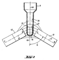
- Fig. 1 shows a recording station for recording a Reaction vessel, which is a suspension of magnetic microparticles contains, the receiving station a separating device for separating contains magnetic microparticles and wherein the separating device there are two magnets between which the reaction vessel is located, characterized in that the magnets 41 and 42 with respect to the Reaction vessel 8 are diametrically opposite and the pole axes 47 of the Magnets 41 and 42 and the longitudinal axis 48 of the reaction vessel 8 a form an acute angle ( ⁇ ).
- the angle ( ⁇ ) is 45 degrees.
- the magnets 41 and 42 are connected to a magnet holder 38, which has a groove 37.
- the magnets 41 and 42 and the magnet holder 38 are part of one Recording station, which is located in a rotor magazine 18.
- the upper edge 46 of the magnets 41 and 42 is below the Suspension surface 51 on which the pole axes 47 of the magnets 41 and 42 cut.
- the magnetic microparticles 27 will be on two diametrically opposite wall areas 28 inside the Reaction vessels 8 which are closest to the magnets 41, 42, deposited.
- the deposits occur in a local area, which ensures that at different filling levels of the Reaction vessel in the course of the test implementation of the Liquid level is always above the deposits 27 and thereby a resuspension can be carried out reliably.
- FIG. 2 shows the deposits of the magnetic microparticles 27 the inner wall 28 of the reaction vessel 8 under the influence of a magnetic Field in a further arrangement of the magnets 41 according to the invention and 42.
- the field lines of the individual magnets are shown schematically.
- the Angle ( ⁇ ) that the polar axis 47 with the longitudinal axis 48 of the Reaction vessel 8 forms is 45 degrees.
- the processing stations 21-25 contain a magnet arrangement 39 consisting of two pairs of magnets 41 and 42, both the 1 with the magnets 41 and 42 as well 8 with the magnets 61 and 62 is possible.
- the Magnets 41 and 42 are in relation to the circle diameter of the Rotor magazine 18 arranged along radii that form an acute angle ( ⁇ ) form. The angle ( ⁇ ) is 20 degrees. Between the magnets 41 and 42 are the reaction vessels 8 in the groove 37 of the magnet holder 38. Die Magnet arrangements 39 are each at an angle of 60 degrees from one another spaced.
- reaction vessels 8 show an overall perspective view of the rotor magazine 18.
- the processing stations 21-26 can be seen. You can see that the Longitudinal axes 48 of the reaction vessels 8 run parallel to the rotor axis of rotation. The bottom 19 of the reaction vessels 8 lies over the groove 37 of the magnet holder 38. 12 reaction vessels 8 are in 6 groups of two in the edge area of the Rotor 18 arranged on a common pitch circle. everyone The group of two is spaced 60 degrees apart.
- Fig. 5 shows a section through a separation device, of Processing station 22 to 26 with the reaction vessels 8. Die Longitudinal axes 48 of the reaction vessels 8 run parallel to the rotor axis of rotation.
- Processing station 22 contains magnets 41 and 42, while Processing station 26 contains no magnets and for resuspension of the serves magnetic microparticles.
- the rotor magazine 18 is in a Magnet holder 38 mounted shaft 43 and a toothed belt drive 44 with connected to a drive motor 45.
- the drive motor 45 can be controlled in cycles that the Reaction vessels 8 each in the corresponding processing stations stand as long as the required processes require.
- the The rotor magazine rotates 30 degrees with each transport cycle. Through the always identical magnet arrangement in the different stations the magnetic microparticles always in identical areas on the Inner wall of the reaction vessel collected.
- FIG. 6 shows a washing device 11 according to the invention, which the rotor magazine 18 and a holder 31 with a resuspension and Contains aspiration device. You can see that again Processing stations 21-26.
- the aspiration used in the processing stations 25 and 26 and resuspension devices are fixed in a holder 31 and via capillary tubes 32 to a supply system (pump, Reservoir etc.) connected.
- the holder 31 is a two-armed Lever formed, the injection nozzles 29 at the one lever end 33 and the aspiration cannulas 35 are arranged on its other lever arm 34 are.
- the lever arm is pivotable about its axis of rotation 36 as well can be lowered vertically. This adjustment is in Fig. 6 with the arrows Pf1, Pf2 indicated.
- the size of the angle adjustment, the distance of the injection and aspiration elements and their arrangement on the corresponding Lever ends of the holder are coordinated so that the Injection elements 29 with those in the processing station 26 or Aspiration cannula 35 with those located in the processing stations 25 Reaction vessels 8 can be brought into alignment for processing.
- the elements that are not in the working position are located above a drainer.
- FIG. 7 shows an overview of the analytical device according to the invention, which is designed, for example, to carry out DNA detections.
- the analyzer 1 contains: Devices for performing the above-mentioned DNA detections, here for example two racks 3, 4 with reagents on a shaking table 5, three racks 7 with disposable reagent containers 8, a temperature-controlled incubator 9, a washing device 11 and a photometer 12.
- the sample and reagent transfer as well as the reaction vessel transfer is moved by one in the x-y coordinate system Transfer head 13 allows a pipetting device 14 and has a reaction vessel gripper 15, both movable in the z direction.
- the washing device can via the gripper 15 Transfer device 13 can be loaded and unloaded.
- process parameters Via an operating level 16 and / or a barcode reading pen 17 process parameters can be entered.
- the CPU controls and coordinates all process operations.
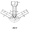
- FIG. 8 shows a further embodiment according to the invention.
- the magnets 61 and 62 shown in FIG. 8 are different from FIG. 1 rotated by 180 °. North and south poles of the magnets 61 shown in FIG. 8 and 62 lie diametrically in the bottom region 19 of the reaction vessel 8 across from.
- the pole axes 67 of the magnets 61 and 62 and the longitudinal axis 48 of the reaction vessel 8 form an acute angle ( ⁇ ) and intersect in the area of the bottom 19.
- the magnets 61 and 62 are, as in FIG. 1 connected to the magnet holder 38, which has a groove 37 into which the Bottom 19 of the reaction vessel 8 protrudes.
- the magnetic Microparticles 27 are diametrically opposed to two Wall areas 28 inside the reaction vessels 8 in the area of Bottom 19 focused.
- the magnets 61 and 62 and the magnet holder 38 are Parts of a receiving station, which is located in a rotor magazine 18.
- FIG. 9 shows the deposits of the magnetic microparticles 27 the inner wall 28 of the reaction vessel 8 under the influence of a magnetic Field in a further arrangement of the magnets 61 according to the invention and 62.
- the field lines of the individual magnets are shown schematically.
- the Angle ( ⁇ ) that the polar axis 67 with the longitudinal axis 48 of the Reaction vessel 8 forms is 45 degrees.
- the two magnet arrangements described above i. H. the Arrangement according to FIG. 1 and the arrangement according to FIG. 8 can also can be used in combination.
- the special magnets 41, 42, 61, 62 have the advantage that they can be used for both magnet arrangements can.
Abstract
Description
Die vorliegende Erfindung betrifft ein Analysengerät der durch den Oberbegriff des Patentanspruchs 1 definierten Art.The present invention relates to an analyzer by Preamble of claim 1 defined Art.
Die Vorrichtung eignet sich beispielsweise zum Einsatz in einer Waschstation eines Analysengerätes zur automatisierten DNA-Detektion oder zur Durchführung von Immunoassays, ist aber nicht auf diese Einsatzgebiete beschränkt.The device is suitable, for example, for use in a Washing station of an analysis device for automated DNA detection or to perform immunoassays, but is not for these uses limited.
Bei vielen Analysenverfahren wie z.B. auch bei der Durchführung von Immunoassays ist die Trennung von fester und flüssiger Phase mit anschliessendem Waschen der festen Phase notwendig. Zum Waschen der festen Phase kann eine bestimmte Menge an Pufferlösung in ein Reaktionsgefäss, das die feste Phase enthält, pipettiert werden. Die feste Phase wird dadurch in der Pufferlösung suspendiert. Anschliessend wird die feste und die flüssige Phase getrennt (Separation). Die flüssige Phase kann abgesaugt werden (Aspiration ). Ein neuer Waschvorgang kann beginnen. Es werden meist mehrere Waschzyklen durchgeführt, die jeweils einen Suspensions-, Separations- und Aspirationsvorgang umfassen.With many analytical methods such as even when performing Immunoassays is the separation of solid and liquid phases subsequent washing of the solid phase necessary. For washing the solid phase can contain a certain amount of buffer solution in one Reaction vessel containing the solid phase can be pipetted. The firm Phase is thereby suspended in the buffer solution. Then the solid and liquid phase separated (separation). The liquid phase can be sucked off (aspiration). A new washing process can begin. It several wash cycles are usually carried out, each one Suspension, separation and aspiration process include.
Bei Verwendung magnetischer Mikropartikel als feste Phase ist die Trennung durch Permanentmagneten im Prinzip bekannt. Die Permanentmagneten ziehen die Mikropartikel an die Wand des Reaktionsgefässes und halten sie dort fest.When using magnetic microparticles as the solid phase, the Separation by permanent magnets known in principle. The Permanent magnets pull the microparticles onto the wall of the Reaction vessel and hold it there.
Eine Vorrichtung der Eingangs erwähnten Art ist aus der EP-A-0 410 645 bekannt. A device of the type mentioned is from EP-A-0 410 645 known.
In der europäischen Patentanmeldung EP 0 136 126 wird eine Vorrichtung zur Durchführung von Trennungen während FestphasenImmunoassays beschrieben, wobei das untere Ende eines Reaktionsgefäss, welches die magnetischen Partikel enthält, zwischen zwei Permanentmagneten angeordnet ist. Die Magnetisierungsachsen liegen senkrecht zur Wand des Reaktionsgefässes. So wird eine Minimierung von magnetischen Streufeldern erreicht.In European patent application EP 0 136 126 a Device for performing separations during solid phase immunoassays described, the lower end of a reaction vessel, which contains the magnetic particles, between two Permanent magnet is arranged. The magnetization axes lie perpendicular to the wall of the reaction vessel. So minimizing stray magnetic fields reached.
In der internationalen Anmeldung WO 92/05443 wird eine Trennvorrichtung für magnetische Mikropartikel beschrieben, wobei die Reaktionsgefässe reihenweise angeordnet sind. Ebenfalls in Reihen sind Magnetblöcke angeordnet, sodass die Reaktionsgefässe an gegenüberliegenden Seiten von Permanentmagneten umgeben sind. Die Polachsen der Magnetblöcke verlaufen parallel. Das bedingt eine Trennung durch Anhäufen der Partikel an einer Seite des Reaktionsgefässes.In international application WO 92/05443 a Separating device for magnetic microparticles described, the Reaction vessels are arranged in rows. Also in rows Magnetic blocks arranged so that the reaction vessels on opposite sides are surrounded by permanent magnets. The Pole axes of the magnetic blocks run parallel. This requires a separation by accumulating the particles on one side of the reaction vessel.
In der deutschen Offenlegungsschrift DE 31 02 029 wird eine
Vorrichtung zum Abtrennen von ferromagnetischen Partikeln aus
Suspensionen mit Hilfe von Permanentmagneten beschrieben, wobei der
Permanentmagnet seitlich angeordnet ist. Der Magnet befindet sich nur auf
einer Seite des Reaktionsgefässes. Dabei ist der Magnet der Form des
Reaktionsgefässes angepasst und bildet einen spitzen Winkel mit der
Längsachse des Reaktionsgefässes. Die Magnetisierungsachse liegt senkrecht
zur Wand des Reaktionsgefässes.In the German
In der amerikanischen Patentschrift US 4,895,650 ist eine Trenneinrichtung beschrieben, wobei die Trennung von Mikropartikeln ebenfalls durch Permanentmagneten erreicht wird. Der Magnet befindet sich nur auf einer Seite des Reaktionsgefässes. In dieser Patentschrift wird die Beziehung zwischen Füllhöhe der Testlösung im Reagenzglas und der Position des Magneten angesprochen. Die Position des Magneten, insbesondere seine Höhe, muss mit der Füllhöhe der Testlösung im Reaktionsgefäss übereinstimmen und wird mit Hilfe von Füllmaterial im unteren Teil der Vorrichtung, die den Magneten trägt, auf die gewünschte Höhe gebracht.In US Pat. No. 4,895,650 there is one Separation device described, the separation of microparticles is also achieved by permanent magnets. The magnet is in place only on one side of the reaction vessel. In this patent the Relationship between the level of the test solution in the test tube and the position of the magnet. The position of the magnet, especially its Height, must match the level of the test solution in the reaction vessel match and is made using filler material in the lower part of the Device that carries the magnet brought to the desired height.
Bei der Durchführung von Immunoassays ist die Füllhöhe im Reaktionsgefäss nach der Zugabe der erforderlichen Reagenzien nicht notwendigerweise einheitlich. So kann z. B. die Füllhöhe im Reaktionsgefäss nach Zugabe von Conjugatlösung geringer sein als die Füllhöhe, die nach Zugabe von Wasch-Pufferlösung entsteht. Bei dem aus US-PS 4,895,650 bekannten Analysenverfahren werden diese unterschiedlichen Füllhöhen nicht berücksichtigt.When performing immunoassays, the fill level is in the Not the reaction vessel after adding the necessary reagents necessarily uniform. So z. B. the level in the reaction vessel after adding conjugate solution be less than the filling level after Addition of washing buffer solution arises. In the case of US Pat. No. 4,895,650 known analytical methods, these different filling levels not considered.
Eine Vorrichtung zur Trennung magnetischer, als feste Phase verwendeten Partikel ist ferner in der nach dem Prioritätsdatum dieser Anmeldung veröffentlichten, älteren europäischen Patentanmeldung EP-A-0 589 636 beschrieben, deren Inhalt als Stand der Technik unter Artikel 54(3) und (4) EPÜ zu berücksichtigen ist. Die in dieser Anmeldung beschriebene Anordnung von Magneten und Leiter des magnetischen Flusses ist so eingerichtet, dass sie nicht auf einen länglichen unteren Teil des Reaktionsgefässes wirkt, sondern nur auf dem Bodenbereich des Reaktionsgefässes. Dabei wird das von den Magneten erzeugte magnetische Feld nicht unmittelbar zum Innenraum des Reaktionsgefässes geführt, sondern durch separate Leiter des magnetischen Flusses, welche zwischen den Magneten und dem Reaktionsgefäss angeordnet sind.A device for separating magnetic, as a solid phase Particle used is also in after the priority date of this Application published earlier European patent application EP-A-0 589 636, the content of which is state of the art under Article 54 (3) and (4) EPC must be taken into account. The one described in this application Arrangement of magnets and conductors of the magnetic flux is like this set up that they are not on an elongated lower part of the Reaction vessel acts, but only on the bottom area of the Reaction vessel. The magnetic generated by the magnets Field does not lead directly to the interior of the reaction vessel, but through separate conductors of the magnetic flux, which between the magnets and the reaction vessel are arranged.
Die bekannten Vorrichtungen zum Trennen von magnetischen Mikropartikeln haben den Nachteil, dass ein relativ langes Zeitintervall erforderlich ist, bis alle Mikropartikel von der flüssigen Phase abgetrennt sind. Speziell bei grösseren Volumen nimmt die Separationszeit beträchtlich zu.The known devices for separating magnetic The disadvantage of microparticles is that they have a relatively long time interval is required until all microparticles are separated from the liquid phase are. Especially with larger volumes, the separation time takes considerably to.
Eine Vorrichtung zur raschen Trennung der magnetischen Mikropartikel
wird in der europäischen Patentanmeldung EP- 317286 beschrieben. Bei
dieser Vorrichtung wird das Reaktionsgefäss von 4 Permanentmagneten
(Magnet 1,2,3 und 4) umgeben, die gleichmässig um das Reaktionsgefäss
angeordnet sind. Die Richtung des Magnetfeldes von Magnet 1 und 3 ist um
180 ° gedreht in bezug auf die Richtung des Magnetfeldes von Magnet 2 und
4.A device for the rapid separation of the magnetic microparticles
is described in European patent application EP-317286. at
this device becomes the reaction vessel of 4 permanent magnets
(
Diese Vorrichtung hat den Nachteil, dass relativ viele Permanentmagnete eingesetzt werden müssen, um die gewünschte Beschleunigung der Trennung zu erreichen. Auch sind dadurch viele Möglichkeiten der Küvettenbewegung nicht realisierbar.This device has the disadvantage that a relatively large number Permanent magnets must be used to get the one you want Achieve acceleration of separation. There are also many Cuvette movement possibilities not feasible.
Der Erfindung liegt daher die Aufgabe zugrunde, ein Analysengerät mit einer Vorrichtung zum Abtrennen magnetischer Mikropartikel bereitzustellen, das bei unterschiedlichen Füllhöhen des Reaktionsgefässes eine rasche Trennung der in Suspension befindlichen magnetischen Mikropartikel erlaubt. Der Erfindung liegt ebenso die Aufgabe zugrunde, eine focussierte Ablagerung der magnetischen Mikropartikel zu ermöglichen. The invention is therefore based on the object of having an analysis device a device for separating magnetic microparticles To provide that at different filling levels of the reaction vessel a rapid separation of the magnetic in suspension Microparticles allowed. The invention is also based on the object to allow focused deposition of the magnetic microparticles.
Erfindungsgemäss wird die Aufgabe durch ein Analysengerät gemäss Patentanspruch 1 gelöst.According to the invention, the task is performed by an analysis device Claim 1 solved.
Bevorzugte Ausführungsformen des erfindungsgemässen Analysengeräts sind durch die abhängigen Ansprüche 2-10 definiert.Preferred embodiments of the analysis device according to the invention are defined by dependent claims 2-10.
Vorzugsweise bilden die Polachsen der Magneten und die Längsachse des Reaktionsgefässes einen Winkel von 45 Grad.The polar axes of the magnets and the longitudinal axis preferably form of the reaction vessel an angle of 45 degrees.
Die Magneten können mit einem Magnethalter verbunden sein, der eine Nut besitzt, in die der Boden des Reaktionsgefässes hineinragt.The magnets can be connected to a magnet holder, the one Has groove into which the bottom of the reaction vessel protrudes.
Die Magneten können in bezug auf das eine Suspension enthaltende Reaktionsgefäss, so angeordnet sein, dass die Polachsen der Magnete sich im Bereich der Suspensionsoberfläche oder im Bereich des Bodens des Reaktionsgefässes schneiden. Die Suspensionsoberfläche ist die Füllhöhe im Reaktionsgefäss nach Zugabe von Waschpufferlösung.The magnets can with respect to the one containing a suspension Reaction vessel, be arranged so that the pole axes of the magnets are in the Area of the suspension surface or in the area of the bottom of the Cut the reaction vessel. The suspension surface is the filling level in the Reaction vessel after adding wash buffer solution.
Die Aufnahmestationen zur Aufnahme der Reaktionsgefässe sind im Rahmen der vorliegenden Erfindung Aufnahmestationen einer Wascheinrichtung. Die erfindungsgemässe Kennvorrichtung lässt sich aber an allen Aufnahmestationen eines Analysengerätes einsetzen, an denen eine Trennung von fester und flüssiger Phase durchgeführt wird.The receiving stations for receiving the reaction vessels are in Within the scope of the present invention recording stations Washing device. The identification device according to the invention can, however Use at all recording stations of an analyzer at which one Separation of solid and liquid phase is carried out.
Die Wascheinrichtung besteht beispielsweise aus einem drehbaren, kreisförmigen Rotormagazin und einem Halter, der eine Resuspensions-und Aspirationsvorrichtung trägt.The washing device consists, for example, of a rotatable, circular rotor magazine and a holder which is a resuspension and Aspiration device carries.
In einer Wascheinrichtung ist die Anordnung von sechs Barbeitungsstationen, die gleichmässig auf einem Rotormagazin verteilt sind, vorteilhaft. Es sind jedoch auch andere Anordnungen der Bearbeitungsstationen denkbar.In a washing facility there are six Processing stations that are evenly distributed on a rotor magazine, advantageous. However, there are other arrangements of the Machining stations conceivable.
Die Wascheinrichtungen können Bearbeitungsstationen zur Trennung von fester und flüssiger Phase mit Magnetanordnungen und Bearbeitungsstationen zur Resuspension ohne Magnetanordnung enthalten. Jede Magnetanordnung besteht vorteilhafterweise aus zwei Paaren von Magneten, zwischen die das Reaktionsgefäss gesetzt wird. Jede Magnetanordnung besteht also aus zwei Aufnahmestationen. Die Magneten der Aufnahmestationen können in bezug auf den Kreisdurchmesser des Rotormagazins entlang Radien angeordnet sein. Je zwei Aufnahmestationen können derart benachbart sein, dass die Radien, entlang derer die beiden Magnete angeordnet sind, einen spitzen Winkel bilden, der vorteilhafterweise 20 Grad beträgt.The washing facilities can use processing stations for separation of solid and liquid phase with magnet arrangements and Processing stations for resuspension without magnet arrangement included. Each magnet arrangement advantageously consists of two pairs of Magnets between which the reaction vessel is placed. each Magnet arrangement thus consists of two recording stations. The magnets of the recording stations can with respect to the circular diameter of the Rotor magazine can be arranged along radii. Two each Pick-up stations can be adjacent such that the radii, along which the two magnets are arranged, an acute angle form, which is advantageously 20 degrees.
Die durch die Erfindung erreichten Vorteile sind im wesentlichen darin zu sehen, dass durch die besondere Ausrichtung der Polachsen mit Schnittpunkt der Polachsen im Bereich der Suspensionsoberfläche die Magnetkraftlinien des Gesamtkraftfeldes so verlaufen, dass das magnetische Streufeld auch zur Trennung der magnetischen Mikropartikel mit ausgenutzt wird. Auch bei maximal möglicher Füllhöhe des Reaktionsgefässes sind die magnetischen Mikropartikel, die sich an der Suspensionsoberfläche befinden, im Einflussbereich des Gesamtkraftfeldes und können schnell und vollständig aus der Suspension abgetrennt werden. Nach der Abtrennung der magnetischen Mikropartikel liegt die Obergrenze der abgetrennten Mikropartikel an gegenüberliegenden Wänden des Reaktionsgefässes stets unterhalb des Flüssigkeitsspiegels, der im Verlauf der Testführung bei Zugabe von Reagenz-bzw. Waschlösungen auftritt.The advantages achieved by the invention are substantial to be seen in the fact that the special alignment of the polar axes with Intersection of the polar axes in the area of the suspension surface Magnetic force lines of the total force field run in such a way that Magnetic stray field also for separating the magnetic microparticles is also exploited. Even at the maximum possible fill level of the Reaction vessels are the magnetic microparticles that adhere to the Suspension surface are in the area of influence of the total force field and can be quickly and completely separated from the suspension. After the magnetic microparticles have been separated, the upper limit is reached of the separated microparticles on opposite walls of the Reaction vessel always below the liquid level, which in the course the test procedure when adding reagent or. Wash solutions occur.
Bei Ausrichtung der Polachsen mit Schnittpunkt der Polachsen im Bereich des Bodens des Reaktionsgefässes wird eine focussierte Ablagerung der magnetischen Mikropartikel an gegenüberliegenden Wänden an der Unterseite des Reaktionsgefässes ermöglicht. Diese Ausführungsform eignet sich zur Trennung von magnetischen Mikropartikeln mit hohem magnetischen Anteilen. Sie ermöglicht eine effizientere Mischung mit nachner zugegebener Flüssigkeit.When aligning the polar axes with the intersection of the polar axes in A focussed deposit becomes the area of the bottom of the reaction vessel of the magnetic microparticles on opposite walls on the Bottom of the reaction vessel allows. This embodiment is suitable for the separation of magnetic microparticles with high magnetic components. It enables a more efficient mix with after added liquid.
In dem erfindungsgmässen Analysengerät kann eine möglichst hohe Leistung, d.h. eine möglichst hohe Anzahl bearbeiteter Proben pro Zeiteinheit bei einer Anlage bestimmter Grösse mit geringstmöglichen Mitteln und bester Zuverlässigkeit erreicht werden.In the analysis device according to the invention, the highest possible Performance, i.e. the highest possible number of processed samples per Unit of time for a plant of a certain size with the smallest possible Medium and best reliability can be achieved.
Der Trennvorgang bzw. Separationsvorgang in einer Waschstation
geht als Zeitfaktor in den Bearbeitungsprozess mit ein. Dieser Zeitfaktor
wird erfindungsgemäss dadurch verringert, dass
Die Taktzeiten sämtlicher Bearbeitungsstationen sind derart aufeinander abgestimmt, dass keine Totzeiten entstehen.The cycle times of all processing stations are such coordinated so that there are no dead times.
Ein Ausführungsbeispiel der Erfindung wird im folgenden anhand der
beiliegenden Zeichnungen beschrieben. Es zeigen:
Beispielhaft wird ein Analysengerät zur automatisierten Durchführung eines Festphasenimmunoassays vorgestellt, bei dem die feste Phase aus magnetischen Mikropartikeln besteht und die Trennung von fester und flüssiger Phase mit Hilfe von Permanentmagneten erfolgt. Nach der Trennung sind die Mikropartikel an zwei diametral gegenüberliegenden Wandungsbereichen des Reaktionsgefässes niedergeschlagen.An automated analysis device is used as an example Performed a solid phase immunoassay presented in which the fixed Phase consists of magnetic microparticles and the separation of solid and liquid phase with the help of permanent magnets. To the separation of the microparticles at two diametrically opposite Wall areas of the reaction vessel deposited.
Fig. 1 zeigt eine Aufnahmestation zur Aufnahme eines
Reaktionsgefässes, das eine Suspension magnetischer Mikropartikel
enthält, wobei die Aufnahmestation eine Trennvorrichtung zum Abtrennen
magnetischer Mikropartikel enthält und wobei die Trennvorrichtung aus
zwei Magneten besteht, zwischen denen sich das Reaktionsgefäss befindet,
dadurch gekennzeichnet, dass sich die Magneten 41 und 42 in bezug auf das
Reaktionsgefäss 8 diametral gegenüberliegen und die Polachsen 47 der
Magneten 41 und 42 und die Längsachse 48 des Reaktionsgefässes 8 einen
spitzen Winkel (α) bilden. Der Winkel (α) beträgt 45 Grad.Fig. 1 shows a recording station for recording a
Reaction vessel, which is a suspension of magnetic microparticles
contains, the receiving station a separating device for separating
contains magnetic microparticles and wherein the separating device
there are two magnets between which the reaction vessel is located,
characterized in that the
Die Magneten 41 und 42 sind mit einem Magnethalter 38 verbunden,
der eine Nut 37 besitzt.The
Die Magneten 41 und 42 und der Magnethalter 38 sind Teile einer
Aufnahmestation, die sich in einem Rotormagazin 18 befindet.The
Die Oberkante 46 der Magnete 41 und 42 liegt unterhalb der
Suspensionsoberfläche 51, an der sich die Polachsen 47 der Magnete 41 und
42 schneiden. Die magnetischen Mikropartikel 27 werden an zwei sich
diametral gegenüberliegenden Wandungsbereichen 28 im Inneren der
Reaktionsgefässe 8, welche den Magneten 41, 42 am nächsten stehen,
abgelagert. Die Ablagerungen erfolgen in einem örtlich begrenzten Bereich,
was sicherstellt, dass bei unterschiedlichen Füllhöhen des
Reaktionsgefässes im Verlauf der Testdurchführung der
Flüssigkeitsspiegel stets oberhalb der Ablagerungen 27 liegt und dadurch
eine Resuspension zuverlässig durchgeführt werden kann.The
Fig. 2 zeigt die Ablagerungen der magnetischen Mikropartikel 27 an
der Innenwand 28 des Reaktionsgefässes 8 im Einfluss eines magnetischen
Feldes bei einer weiteren erfindungsgemässen Anordnung der Magnete 41
und 42. Die Feldlinien der Einzelmagnete sind schematisch dargestellt. Der
Winkel (α), den die Polachse 47 mit der Längsachse 48 des
Reaktionsgefässes 8 bildet, beträgt 45 Grad.2 shows the deposits of the
Fig.3 zeigt sechs Bearbeitungsstationen 21-26 radial auf einem
kreisförmigen, drehbaren Rotormagazin 18 angeordnet, wobei die
Bearbeitungsstationen 21-24 zur Trennung von fester und flüssiger Phase
dienen, die Aspiration in Bearbeitungsstation 25 und die Resuspension in
Bearbeitungsstation 26 erfolgt, und wobei die Bearbeitungsstationen 21-25
Vorrichtungen zum Abtrennen der magnetischen Mikropartikel enthalten.
Die Bearbeitungsstationen 21-25 enthalten eine Magnetanordnung 39
bestehend aus je zwei Paaren von Magneten 41 und 42, wobei sowohl die
Ausführungsform nach Fig. 1 mit den Magneten 41 und 42 als auch die
Ausführungsform nach Fig. 8 mit den Magneten 61 und 62 möglich ist. Die
Magneten 41 und 42 sind in bezug auf den Kreisdurchmesser des
Rotormagazins 18 entlang Radien angeordnet, die einen spitzen Winkel (β)
bilden. Der Winkel (β) beträgt 20 Grad. Zwischen den Magneten 41 und 42
befinden sich die Reaktionsgefässe 8 in der Nut 37 des Magnethalters 38. Die
Magnetanordnungen 39 sind jeweils im Winkel von 60 Grad voneinander
beabstandet.3 shows six processing stations 21-26 radially on one
circular,
Fig. 4 zeigt eine perspektivische Gesamtansicht des Rotormagazins 18.
Man erkennt die Bearbeitungsstationen 21-26. Man erkennt, dass die
Längsachsen 48 der Reaktionsgefässe 8 parallel zur Rotordrehachse laufen.
Der Boden 19 der Reaktionsgefässe 8 liegt über der Nut 37 des Magnethalters
38. 12 Reaktionsgefässe 8 sind in 6 Zweiergruppen im Randbereich des
Rotors 18 auf einem gemeinsamen Teilkreis angeordnet. Jeder
Zweiergruppe ist jeweils im Winkel von 60 Grad voneinander beabstandet.4 shows an overall perspective view of the
Fig. 5 zeigt einen Schnitt durch eine Trenneinrichtung, von
Bearbeitungsstation 22 nach 26 mit den Reaktionsgefässen 8. Die
Längsachsen 48 der Reaktionsgefässe 8 laufen parallel zur Rotordrehachse.
Bearbeitungsstation 22 enthält die Magnete 41 und 42, während
Bearbeitungsstation 26 keine Magnete enthält und zur Resuspension der
magnetischen Mikropartikel dient. Das Rotormagazin 18 ist über eine im
Magnethalter 38 gelagerte Welle 43 und einen Zahnriemenantrieb 44 mit
einem Antriebsmotor 45 verbunden.Fig. 5 shows a section through a separation device, of
Der Antriebsmotor 45 ist derart taktweise steuerbar, dass die
Reaktionsgefässe 8 jeweils in den entsprechenden Bearbeitungsstationen zu
stehen kommen, solange wie es die erforderlichen Prozesse verlangen. Das
Rotormagazin dreht sich bei jedem Transporttakt um 30 Grad. Durch die
stets identische Magnetanordnung in den verschiedenen Stationen werden
die magnetischen Mikropartikel stets an identischen Bereichen an der
Innenwand des Reaktionsgefässes gesammelt.The
In Fig. 6 ist eine erfindungsgemässe Wascheinrichtung 11 dargestellt,
die das Rotormagazin 18 sowie einen Halter 31 mit einer Resuspensions-und
Aspirationsvorrichtung enthält. Man erkennt wieder die
Bearbeitungsstationen 21-26.6 shows a
Die in den Bearbeitungstationen 25 und 26 eingesetzten Aspirations-
und Resuspensionsvorrichtungen sind in einem Halter 31 festgelegt und
über Kapillarröhrchen 32 an ein Versorgungssystem (Pumpe,
Vorratsbehälter usw.) angeschlossen. Der Halter 31 ist als zweiarmiger
Hebel ausgebildet, wobei an dem einen Hebelende 33 die Einspritzdüsen 29
und an dessen anderem Hebelarm 34 die Aspirationskanülen 35 angeordnet
sind. Der Hebelarm ist um seine Drehachse 36 verschwenkbar sowie
vertikal absenkbar. Diese Verstellung ist in Fig. 6 mit den Pfeilen Pf1, Pf2
angedeutet. Die Grösse der Winkelverstellung, der Abstand der Einspritz-
und Aspirationselemente und deren Anordnung an den entsprechenden
Hebelenden des Halters ist dabei derart aufeinander abgestimmt, dass die
Einspritzelemente 29 mit den in der Bearbeitungsstation 26 oder die
Aspirationkanüle 35 mit den in den Bearbeitungsstationen 25 befindlichen
Reaktionsgefässen 8 zur Bearbeitung in Flucht gebracht werden können.
Die nicht in Arbeitsposition befindlichen Elemente befinden sich dabei über
einem Abtropfbehälter.The aspiration used in the
Fig. 7 zeigt eine Uebersichtsdarstellung des erfindungsgemässen
Analysengerätes, welches beispielsweise zur Durchführung von DNA-Detektionen
ausgelegt ist. In dem Analysengerät 1 sind enthalten:
Einrichtungen zur Durchführung obengenannter DNA-Detektionen, hier
z.B. zwei Racks 3, 4 mit Reagenzien auf einem Schütteltisch 5, drei Racks 7
mit Einwegreagenzbehältern 8, ein temperierbarer Inkubator 9, eine
Wascheinrichtung 11 und ein Photometer 12.FIG. 7 shows an overview of the analytical device according to the invention, which is designed, for example, to carry out DNA detections. The analyzer 1 contains:
Devices for performing the above-mentioned DNA detections, here for example two
Der Proben- und Reagenzientransfer sowie der Reaktionsgefässe-Transfer
wird durch einen im x-y-Koordinatensystem bewegbaren
Transferkopf 13 ermöglicht, welcher eine Pipettiereinrichtung 14 sowie
einen Reaktionsgefässegreifer 15, beide in z-Richtung bewegbar, aufweist.The sample and reagent transfer as well as the reaction vessel transfer
is moved by one in the x-y coordinate
Die Wascheinrichtung kann über den Greifer 15 der
Transfereinrichtung 13 be- und entladen werden.The washing device can via the gripper 15
Ueber eine Bedienebene 16 und / oder einen Barcode-Lesegriffel 17
können Prozessparameter eingegeben werden. Die CPU steuert und
koordiniert sämtliche Prozessvorgänge.Via an
Fig. 8 zeigt eine weitere erfindungsgemässe Ausführungsform. Im
Unterschied zu Fig. 1 sind die in Fig. 8 dargestellten Magneten 61 und 62
um 180° gedreht. Nord-und Südpol der in Fig. 8 dargestelleten Magneten 61
und 62 liegen sich im Bodenbereich 19 des Reaktionsgefässes 8 diametral
gegenüber. Die Polachsen 67 der Magnete 61 und 62 und die Längsachse 48
des Reaktionsgefässes 8 bilden einen spitzen Winkel (α) und schneiden sich
im Bereich des Bodens 19. Die Magneten 61 und 62 sind ebenso wie in Fig.
1 mit dem Magnethalter 38 verbunden, der eine Nut 37 besitzt, in die der
Boden 19 des Reaktionsgefässes 8 hineinragt. Die magnetischen
Mikropartikel 27 werden an zwei sich diametral gegenüberliegenden
Wandungsbereichen 28 im Inneren der Reaktionsgefässe 8 im Bereich des
Bodens 19 focussiert. Die Magneten 61 und 62 und der Magnethalter 38 sind
Teile einer Aufnahmestation, die sich in einem Rotormagazin 18 befindet.8 shows a further embodiment according to the invention. in the
Fig. 9 zeigt die Ablagerungen der magnetischen Mikropartikel 27 an
der Innenwand 28 des Reaktionsgefässes 8 im Einfluss eines magnetischen
Feldes bei einer weiteren erfindungsgemässen Anordnung der Magnete 61
und 62. Die Feldlinien der Einzelmagnete sind schematisch dargestellt. Der
Winkel (α), den die Polachse 67 mit der Längsachse 48 des
Reaktionsgefässes 8 bildet, beträgt 45 Grad.9 shows the deposits of the
Die zwei oben beschriebenen Magnetanordnungen, d. h. die
Anordnung gemäss Fig. 1 und die Anordnung gemäss Fig. 8 können auch
kombiniert verwendet werden. Die speziellen Magnete 41, 42, 61, 62 haben
den Vorteil, dass sie für beide Magnetanordnungen verwendet werden
können.The two magnet arrangements described above, i. H. the
Arrangement according to FIG. 1 and the arrangement according to FIG. 8 can also
can be used in combination. The
Claims (10)
- An analytical device comprising a reaction vessel (8) and at least one treatment station for receiving a reaction vessel, the reaction vessel, (8) comprising an elongate bottom part with a subtanstially constant cross-section, a closed base (19) and a longitudinal axis (48), and containing a suspension of magnetic microparticles (27), which suspension has a surface (51), the at least one treatment station containing a separating device for separating the magnetic microparticles, the separating device consisting of two magnets (41, 42; 61, 62) and an elongate zone of the bottom part of the reaction vessel (8) being disposed between the north pole of one magnet (41, 61) and the south pole of the other magnet (42, 62), the north pole of one magnet (41, 61) being situated opposite the south pole of the other magnet (42, 62) and solely one air gap is situated between each of the magnets and the reaction vessel, which analytical device is characterised in that the pole axis (47) of each of the magnets (41, 42) forms an acute angle α with the longitudinal axis (48) of the reaction vessel (8).
- An analytical device according to claim 1, characterised in that the acute angle α is 45°.
- An analytical device according to claim 1, characterised in that the magnets (61, 62) are connected to a magnet holder (38) which has a groove (37) into which the base (19) of the reaction vessel (8) projects.
- An analytical device according to claim 1, characterised in that the magnets (41, 42) are so disposed with respect to the reaction vessel (8) that the top edge (46) of the magnets (41, 42) lies beneath the suspension surface (51) and the pole axes (47) of the magnets (41, 42) intersect at the suspension surface (51).
- An analytical device according to claim 1, characterised in that the magnets (61, 62) are so disposed with respect to the reaction vessel (8) that the poles of the two magnets (61, 62) are situated at a level lying in the region of the base (19) and that the pole axes (67) of the magnets (61, 62) intercept at a point situated along the longitudinal axis of the reaction vessel and at a height in the region of the base (19).
- An analytical device according to claim 1, characterised in that n treatment stations for receiving the reaction vessels are disposed on a circular rotor magazine (18), n being an integer between 1 and 20.
- An analytical device according to claim 6, characterised in that the rotor magazine (18) is part of a washing device (11) which contains at least one treatment station (25) for aspiration, at least one treatment station (26) for the resuspension of magnetic particles and a plurality of treatment stations (21-24) for separating solid and liquid phases, each of the treatment stations for separation (21-24) and for aspiration (25) containing a receiving station with a separating device according to claim 4 or 5 for separating the magnetic microparticles.
- An analytical device according to claims 6 and 7, characterised in that the receiving stations in the treatment stations (21-25) contain a paired arrangement (39) of magnets (41, 42; 61, 62), the magnets (41, 42; 61, 62) being disposed, with respect to the diameter of the circle of the rotor magazine (18) along radii which form an acute angle β.
- An analytical device according to claim 8, characterised in that the angle β is 20°.
- An analytical device according to any one of claims 6 to 9, characterised in that the rotor magazine (18) is connected, via a shaft (43) mounted in the magnet holder (38) and a toothed belt drive (44), to a drive motor (45) which is cyclically controllable in such manner that the reaction vessel (8) in each case comes to rest in the treatment stations (21-26).
Applications Claiming Priority (3)
| Application Number | Priority Date | Filing Date | Title |
|---|---|---|---|
| CH280193 | 1993-09-17 | ||
| CH280193 | 1993-09-17 | ||
| CH2801/93 | 1993-09-17 |
Publications (2)
| Publication Number | Publication Date |
|---|---|
| EP0644425A1 EP0644425A1 (en) | 1995-03-22 |
| EP0644425B1 true EP0644425B1 (en) | 2002-01-30 |
Family
ID=4241900
Family Applications (1)
| Application Number | Title | Priority Date | Filing Date |
|---|---|---|---|
| EP94113653A Expired - Lifetime EP0644425B1 (en) | 1993-09-17 | 1994-09-01 | Analyser having a device for separating magnetic microparticles |
Country Status (7)
| Country | Link |
|---|---|
| US (1) | US5705062A (en) |
| EP (1) | EP0644425B1 (en) |
| JP (1) | JP2825768B2 (en) |
| AT (1) | ATE212723T1 (en) |
| CA (1) | CA2131843A1 (en) |
| DE (1) | DE59410037D1 (en) |
| ES (1) | ES2170083T3 (en) |
Cited By (1)
| Publication number | Priority date | Publication date | Assignee | Title |
|---|---|---|---|---|
| US9150908B2 (en) | 1998-05-01 | 2015-10-06 | Gen-Probe Incorporated | Method for detecting the presence of a nucleic acid in a sample |
Families Citing this family (83)
| Publication number | Priority date | Publication date | Assignee | Title |
|---|---|---|---|---|
| US6537817B1 (en) | 1993-05-31 | 2003-03-25 | Packard Instrument Company | Piezoelectric-drop-on-demand technology |
| DE4429155A1 (en) | 1994-08-17 | 1996-02-22 | Hans Schiesl | Measuring arrangement and method for carrying out luminometric series analyzes as well as multiple cuvette for taking liquid samples therefor |
| US20030127396A1 (en) * | 1995-02-21 | 2003-07-10 | Siddiqi Iqbal Waheed | Apparatus and method for processing magnetic particles |
| US6884357B2 (en) | 1995-02-21 | 2005-04-26 | Iqbal Waheed Siddiqi | Apparatus and method for processing magnetic particles |
| DE19512368A1 (en) * | 1995-04-01 | 1996-10-02 | Boehringer Mannheim Gmbh | Nucleic acid release and isolation system |
| US6919175B1 (en) | 1995-04-01 | 2005-07-19 | Roche Diagnostics Gmbh | System for releasing and isolating nucleic acids |
| US6299839B1 (en) * | 1995-08-31 | 2001-10-09 | First Medical, Inc. | System and methods for performing rotor assays |
| CA2255658C (en) * | 1996-05-20 | 2007-07-17 | Precision System Science Co., Ltd. | Method and apparatus for controlling magnetic particles by pipetting machine |
| US6558947B1 (en) | 1997-09-26 | 2003-05-06 | Applied Chemical & Engineering Systems, Inc. | Thermal cycler |
| US6106784A (en) * | 1997-09-26 | 2000-08-22 | Applied Chemical & Engineering Systems, Inc. | Thawing station |
| DE69839294T2 (en) * | 1997-09-29 | 2009-04-09 | F. Hoffmann-La Roche Ag | Apparatus for depositing magnetic particles |
| EP1671703A3 (en) * | 1998-03-19 | 2006-07-05 | Precision System Science Co., Ltd. | Method for making substances in carriers |
| US8337753B2 (en) * | 1998-05-01 | 2012-12-25 | Gen-Probe Incorporated | Temperature-controlled incubator having a receptacle mixing mechanism |
| AU4093699A (en) * | 1998-05-22 | 1999-12-13 | Nichols Institute Diagnostics | Magnetic particle suspending device, apparatus and methods for using same |
| DE19823719B4 (en) * | 1998-05-27 | 2011-12-15 | MAX-PLANCK-Gesellschaft zur Förderung der Wissenschaften e.V. | Method for concentrating substances |
| DE59912484D1 (en) * | 1998-07-31 | 2005-10-06 | Tecan Trading Ag Maennedorf | magnetic separator |
| US6776174B2 (en) * | 1998-08-21 | 2004-08-17 | Paul E. Nisson | Apparatus for washing magnetic particles |
| US6357907B1 (en) * | 1999-06-15 | 2002-03-19 | V & P Scientific, Inc. | Magnetic levitation stirring devices and machines for mixing in vessels |
| CA2387793C (en) * | 1999-10-15 | 2008-01-08 | Packard Instrument Company, Inc. | Piezoelectric-drop-on-demand technology |
| US7390459B2 (en) * | 1999-12-13 | 2008-06-24 | Illumina, Inc. | Oligonucleotide synthesizer |
| EP1239952B1 (en) * | 1999-12-13 | 2011-10-05 | Illumina, Inc. | Oligonucleotide synthesizer using centrifugal force |
| US6672458B2 (en) * | 2000-05-19 | 2004-01-06 | Becton, Dickinson And Company | System and method for manipulating magnetically responsive particles fluid samples to collect DNA or RNA from a sample |
| DE10156790A1 (en) * | 2001-11-19 | 2003-06-18 | Chemagen Biopolymer Technologi | Device and method for treating magnetic particles |
| JP2005522679A (en) * | 2002-04-12 | 2005-07-28 | インストゥルメンテイション ラボラトリー カンパニー | Immunoassay probe |
| US7601491B2 (en) * | 2003-02-06 | 2009-10-13 | Becton, Dickinson And Company | Pretreatment method for extraction of nucleic acid from biological samples and kits therefor |
| US20040157219A1 (en) * | 2003-02-06 | 2004-08-12 | Jianrong Lou | Chemical treatment of biological samples for nucleic acid extraction and kits therefor |
| US20050239091A1 (en) * | 2004-04-23 | 2005-10-27 | Collis Matthew P | Extraction of nucleic acids using small diameter magnetically-responsive particles |
| US8211386B2 (en) | 2004-06-08 | 2012-07-03 | Biokit, S.A. | Tapered cuvette and method of collecting magnetic particles |
| EP1621890A1 (en) | 2004-07-26 | 2006-02-01 | bioMerieux B.V. | Device and method for separating, mixing and concentrating magnetic particles with a fluid and use thereof in purification methods |
| JP2008511816A (en) * | 2004-08-03 | 2008-04-17 | ベクトン・ディキンソン・アンド・カンパニー | Use of magnetic materials to separate samples |
| AU2005271688B2 (en) * | 2004-08-03 | 2011-10-06 | Becton, Dickinson And Company | Use of magnetic material to direct isolation of compounds and fractionation of multipart samples |
| CA2871777C (en) * | 2005-03-10 | 2015-07-28 | Matthew J. Hayes | System and methods for detecting multiple optical signals |
| US20100213136A1 (en) * | 2005-06-23 | 2010-08-26 | Koninklijke Philips Electronics, N.V. | Apparatus for moving magnetic particles |
| EP1839756A1 (en) * | 2006-03-31 | 2007-10-03 | F.Hoffmann-La Roche Ag | Apparatus for separating magnetic particles from liquids containing said particles, and an array of vessels suitable for use with such an apparatus |
| JP2007319735A (en) * | 2006-05-30 | 2007-12-13 | Fuji Xerox Co Ltd | Microreactor and method for cleaning micro flow path |
| US8246919B2 (en) | 2006-09-21 | 2012-08-21 | Abbott Laboratories | Specimen sample rack |
| US8795609B2 (en) * | 2007-02-08 | 2014-08-05 | Biokit, S.A. | Magnetic particle washing station |
| US9199247B2 (en) * | 2007-05-29 | 2015-12-01 | Invitrogen Dynal As | Magnetic separation rack |
| GB0724404D0 (en) * | 2007-05-29 | 2008-01-30 | Invitrogen Dynal As | A sample vessel retaining portion |
| US7883265B2 (en) * | 2007-06-01 | 2011-02-08 | Applied Biosystems, Llc | Devices, systems, and methods for preparing emulsions |
| JP5232858B2 (en) * | 2007-06-29 | 2013-07-10 | ベクトン・ディキンソン・アンド・カンパニー | Method for extracting and purifying components of biological samples |
| TWI325337B (en) * | 2007-07-26 | 2010-06-01 | Ind Tech Res Inst | Magnetic separation device |
| TWI316874B (en) * | 2007-07-26 | 2009-11-11 | Ind Tech Res Inst | Magnetic separation device |
| CN101377456B (en) * | 2007-08-27 | 2010-12-08 | 财团法人工业技术研究院 | Magnetic conversion separating apparatus |
| JP4586054B2 (en) * | 2007-08-31 | 2010-11-24 | 株式会社日立ハイテクノロジーズ | Automatic analyzer |
| US8685322B2 (en) | 2007-11-13 | 2014-04-01 | Stratec Biomedical Ag | Apparatus and method for the purification of biomolecules |
| EP2208531A1 (en) * | 2008-12-30 | 2010-07-21 | Atonomics A/S | Distribution of particles in capillary channel by application of magnetic field |
| TWI429475B (en) * | 2009-10-30 | 2014-03-11 | Rbc Bioscience Corp | Integral-type reaction cartridge |
| CN103657754B (en) | 2010-07-23 | 2016-01-06 | 贝克曼考尔特公司 | Pipette |
| US9046507B2 (en) | 2010-07-29 | 2015-06-02 | Gen-Probe Incorporated | Method, system and apparatus for incorporating capacitive proximity sensing in an automated fluid transfer procedure |
| US9144801B2 (en) | 2010-08-31 | 2015-09-29 | Abbott Laboratories | Sample tube racks having retention bars |
| WO2012116308A1 (en) | 2011-02-24 | 2012-08-30 | Gen-Probe Incorporated | Systems and methods for distinguishing optical signals of different modulation frequencies in an optical signal detector |
| JP6072033B2 (en) | 2011-07-29 | 2017-02-01 | コーニング インコーポレイテッド | Magnetic separation apparatus and method |
| BR112014011035A2 (en) | 2011-11-07 | 2017-06-13 | Beckman Coulter, Inc. | aliquot system and workflow |
| CN104105969B (en) | 2011-11-07 | 2016-10-12 | 贝克曼考尔特公司 | Centrifuge system and workflow |
| EP2776848B1 (en) | 2011-11-07 | 2019-12-25 | Beckman Coulter, Inc. | System and method for transporting sample containers |
| BR112014011048A2 (en) | 2011-11-07 | 2017-05-02 | Beckman Coulter Inc | robotic arm |
| EP2776844B1 (en) | 2011-11-07 | 2020-09-30 | Beckman Coulter, Inc. | Specimen container detection |
| CN103975245A (en) | 2011-11-07 | 2014-08-06 | 贝克曼考尔特公司 | Magnetic damping for specimen transport system |
| USD709623S1 (en) | 2011-12-22 | 2014-07-22 | Eppendorf Ag | Pipette barrel |
| USD706946S1 (en) | 2011-12-22 | 2014-06-10 | Eppendorf Ag | Pipette |
| CN103376333B (en) * | 2012-04-17 | 2015-09-16 | 深圳迈瑞生物医疗电子股份有限公司 | Automatic clinical chemistry analyzer |
| US9199870B2 (en) | 2012-05-22 | 2015-12-01 | Corning Incorporated | Electrostatic method and apparatus to form low-particulate defect thin glass sheets |
| IN2014DN06822A (en) * | 2012-08-31 | 2015-05-22 | Toshiba Kk | |
| CN102954954B (en) * | 2012-09-19 | 2014-07-16 | 东南大学 | Magnetic separation-based multi-sample multi-site high-flux nucleic acid analysis system |
| US9400285B2 (en) | 2013-03-15 | 2016-07-26 | Abbot Laboratories | Automated diagnostic analyzers having vertically arranged carousels and related methods |
| ES2901756T3 (en) | 2013-03-15 | 2022-03-23 | Abbott Lab | Automated diagnostic analyzers having rear accessible track systems and related methods |
| JP6165961B2 (en) | 2013-03-15 | 2017-07-19 | アボット・ラボラトリーズAbbott Laboratories | Diagnostic analyzer with pre-process carousel and associated method |
| US9504981B2 (en) * | 2013-05-15 | 2016-11-29 | True Health Diagnostics Llc | Methods for purifying nucleic acids and devices thereof |
| ES2724537T3 (en) * | 2013-12-03 | 2019-09-11 | Immunodiagnostic Systems Ltd | Procedure for quantifying an analyte, and an automatic analytical device configured to implement said procedure |
| USD805651S1 (en) | 2013-12-12 | 2017-12-19 | Eppendorf Ag | Flange for a pipette adapter |
| WO2015126340A1 (en) * | 2014-02-18 | 2015-08-27 | Anatoli̇a Tani Ve Bi̇yoteknoloji̇ Ürünleri̇ Araştirma Geli̇şti̇rme Sanayi̇ Ve Ti̇caret Anoni̇m Şi̇rketi̇ | A laboratory equipment utilized to isolate nucleic acids manually via magnetic particles and to prepare them for molecular genetic analyses |
| US9663780B2 (en) | 2014-10-15 | 2017-05-30 | Alpaqua Engineering, LLC | Solid-core ring-magnet |
| US10094842B2 (en) | 2014-10-17 | 2018-10-09 | Shenzhen Mindray Bio-Medical Electronics Co., Ltd. | Automatic biochemical analyzer |
| JP6472973B2 (en) | 2014-10-24 | 2019-02-20 | 日本電子株式会社 | Automatic analyzer and separation cleaning method |
| AU2016200047A1 (en) * | 2015-01-07 | 2016-07-21 | Personal Genomics, Inc. | Oriented Loading Systems And Method For Orienting A Particle Loaded In A Well |
| CZ306187B6 (en) * | 2015-02-26 | 2016-09-14 | Univerzita Palackého v Olomouci | Apparatus for magnetic separation of ferromagnetic particles, set for magnetic separation of particles, separation process of magnetic particles from a solution and use of the apparatus or set for magnetic separation of particles |
| CN107430058A (en) * | 2015-02-27 | 2017-12-01 | Hycor生物医学有限责任公司 | For the apparatus and method for the content for suspending and washing multiple test glass |
| US10427162B2 (en) | 2016-12-21 | 2019-10-01 | Quandx Inc. | Systems and methods for molecular diagnostics |
| US11242519B2 (en) | 2018-08-23 | 2022-02-08 | Alpaqua Engineering, LLC | Discontinuous wall hollow core magnet |
| US11684926B2 (en) * | 2019-07-14 | 2023-06-27 | Zhuhai Sanmed Biotech Ltd. | System and processes for isolation and enrichment by magnetic separation |
| JP7322195B2 (en) * | 2020-02-07 | 2023-08-07 | 積水メディカル株式会社 | automatic analyzer |
| DE202021105458U1 (en) * | 2021-10-08 | 2023-01-24 | Sanolibio Co., Ltd. | Device for the magnetic purification of biological samples |
Family Cites Families (14)
| Publication number | Priority date | Publication date | Assignee | Title |
|---|---|---|---|---|
| DE3102029A1 (en) * | 1981-01-22 | 1982-08-26 | Europäisches Laboratorium für Molekularbiologie (EMBL), 6900 Heidelberg | Appliance for separating ferromagnetic particles |
| JPS5852718B2 (en) * | 1981-12-01 | 1983-11-24 | 清進産業株式会社 | Method and device for separating suspended matter in wastewater treatment |
| CA1220168A (en) * | 1983-09-09 | 1987-04-07 | Henry J. Rahn | Magnetic separator for solid phase immunoassays |
| JPS62133354A (en) * | 1985-12-06 | 1987-06-16 | Nitsuteku:Kk | Stirrer for eia analyzer |
| DE3850635T2 (en) * | 1987-11-16 | 1995-03-02 | Amoco Corp | Magnetic separator and method for use in heterogeneous tests. |
| JPH01136068A (en) * | 1987-11-20 | 1989-05-29 | Hitachi Ltd | Automatic analyzer |
| US4895650A (en) * | 1988-02-25 | 1990-01-23 | Gen-Probe Incorporated | Magnetic separation rack for diagnostic assays |
| JPH02307059A (en) * | 1989-05-23 | 1990-12-20 | Seiko Instr Inc | Reaction vessel |
| IL94212A0 (en) * | 1989-07-24 | 1991-01-31 | Tri Tech Partners And Triton B | Automated analytical apparatus and method |
| JP2878785B2 (en) * | 1990-05-17 | 1999-04-05 | 株式会社東芝 | Immunoassay system |
| WO1992005443A1 (en) * | 1990-09-15 | 1992-04-02 | Medical Research Council | Reagent separation |
| JP2548626B2 (en) * | 1990-11-21 | 1996-10-30 | 三井製薬工業株式会社 | Immune automatic analyzer |
| JPH04271823A (en) * | 1991-02-26 | 1992-09-28 | Kyoto Daiichi Kagaku:Kk | Stirring device for liquid in cell |
| EP0589636B1 (en) * | 1992-09-24 | 2000-08-02 | Amersham Pharmacia Biotech UK Limited | Magnetic separation method and apparatus therefor |
-
1994
- 1994-09-01 AT AT94113653T patent/ATE212723T1/en not_active IP Right Cessation
- 1994-09-01 EP EP94113653A patent/EP0644425B1/en not_active Expired - Lifetime
- 1994-09-01 DE DE59410037T patent/DE59410037D1/en not_active Expired - Lifetime
- 1994-09-01 ES ES94113653T patent/ES2170083T3/en not_active Expired - Lifetime
- 1994-09-07 US US08/301,857 patent/US5705062A/en not_active Expired - Lifetime
- 1994-09-12 CA CA002131843A patent/CA2131843A1/en not_active Abandoned
- 1994-09-16 JP JP6221895A patent/JP2825768B2/en not_active Expired - Fee Related
Cited By (2)
| Publication number | Priority date | Publication date | Assignee | Title |
|---|---|---|---|---|
| US9150908B2 (en) | 1998-05-01 | 2015-10-06 | Gen-Probe Incorporated | Method for detecting the presence of a nucleic acid in a sample |
| US9598723B2 (en) | 1998-05-01 | 2017-03-21 | Gen-Probe Incorporated | Automated analyzer for performing a nucleic acid-based assay |
Also Published As
| Publication number | Publication date |
|---|---|
| CA2131843A1 (en) | 1995-03-18 |
| JPH07181188A (en) | 1995-07-21 |
| ES2170083T3 (en) | 2002-08-01 |
| US5705062A (en) | 1998-01-06 |
| DE59410037D1 (en) | 2002-03-14 |
| EP0644425A1 (en) | 1995-03-22 |
| ATE212723T1 (en) | 2002-02-15 |
| JP2825768B2 (en) | 1998-11-18 |
Similar Documents
| Publication | Publication Date | Title |
|---|---|---|
| EP0644425B1 (en) | Analyser having a device for separating magnetic microparticles | |
| EP0644426B1 (en) | Analyser with a device for suspending particles, and suspension method therefor | |
| DE69839294T2 (en) | Apparatus for depositing magnetic particles | |
| EP1446668B1 (en) | Device and method for treating magnetic particles | |
| EP2030689B1 (en) | Microplate support with magnets | |
| EP1843854B1 (en) | Device and method for the elimination of magnetic or magnetizable particles from a liquid | |
| EP1919625A1 (en) | Device and method for the elimination of magnetic particles from a liquid | |
| EP1110609B1 (en) | System for sample processing in a multi-chamber device | |
| EP0893692B1 (en) | Multiple cuvette for liquid samples | |
| DE60210946T2 (en) | GRIPPING MECHANISM, DEVICE AND METHOD | |
| EP0408804B1 (en) | Analyser for heterogeneous immuno assays | |
| EP1644120B1 (en) | Device and method for removing magnetic or magnetisable particles from a liquid | |
| DE10057396C1 (en) | Separation of e.g. biomolecules from dispersion or solution, employs magnetic particles onto which substance is sorbed, and electromagnet for their extraction | |
| DE60207564T2 (en) | TREATMENT METHOD FOR MAGNETIC PARTICLES AND BIOANALYSIS APPARATUS USING MAGNETIC APPLICATION | |
| EP2927163A1 (en) | Vertical conveyor, sample distribution system and laboratory automation system | |
| DE4423878A1 (en) | Device and method for separating magnetic microparticles | |
| EP0849584A2 (en) | Apparatus (cuvette) for receiving and storing liquids and for performing optical measurements | |
| DE60037271T2 (en) | ANALYZER WITH A ROTATABLE FRAME STAND | |
| DE69833846T2 (en) | Device for conveying components within an automatic analysis system | |
| DE10063984A1 (en) | Laboratory separator for magnetic particles employed in molecular biology, employs a moving magnet holder contacting reaction vessel to draw particles against its wall | |
| EP3270167A1 (en) | Transport of liquid containers in an automatic analyzer | |
| DE4034551C2 (en) | ||
| EP1291647B1 (en) | Magnetic gripping device for changing elongated probes in an X-ray analyser | |
| EP1291648B1 (en) | Space-saving housing for an X-ray apparatus with sample changer | |
| EP1814700A1 (en) | Device for coupling an attachment |
Legal Events
| Date | Code | Title | Description |
|---|---|---|---|
| PUAI | Public reference made under article 153(3) epc to a published international application that has entered the european phase |
Free format text: ORIGINAL CODE: 0009012 |
|
| 17P | Request for examination filed |
Effective date: 19940901 |
|
| AK | Designated contracting states |
Kind code of ref document: A1 Designated state(s): AT BE CH DE DK ES FR GB GR IE IT LI LU NL PT |
|
| 17Q | First examination report despatched |
Effective date: 19971128 |
|
| GRAG | Despatch of communication of intention to grant |
Free format text: ORIGINAL CODE: EPIDOS AGRA |
|
| GRAG | Despatch of communication of intention to grant |
Free format text: ORIGINAL CODE: EPIDOS AGRA |
|
| GRAG | Despatch of communication of intention to grant |
Free format text: ORIGINAL CODE: EPIDOS AGRA |
|
| GRAH | Despatch of communication of intention to grant a patent |
Free format text: ORIGINAL CODE: EPIDOS IGRA |
|
| GRAH | Despatch of communication of intention to grant a patent |
Free format text: ORIGINAL CODE: EPIDOS IGRA |
|
| GRAA | (expected) grant |
Free format text: ORIGINAL CODE: 0009210 |
|
| REG | Reference to a national code |
Ref country code: GB Ref legal event code: IF02 |
|
| AK | Designated contracting states |
Kind code of ref document: B1 Designated state(s): AT BE CH DE DK ES FR GB GR IE IT LI LU NL PT |
|
| PG25 | Lapsed in a contracting state [announced via postgrant information from national office to epo] |
Ref country code: IE Free format text: LAPSE BECAUSE OF FAILURE TO SUBMIT A TRANSLATION OF THE DESCRIPTION OR TO PAY THE FEE WITHIN THE PRESCRIBED TIME-LIMIT Effective date: 20020130 Ref country code: GR Free format text: LAPSE BECAUSE OF FAILURE TO SUBMIT A TRANSLATION OF THE DESCRIPTION OR TO PAY THE FEE WITHIN THE PRESCRIBED TIME-LIMIT Effective date: 20020130 |
|
| REF | Corresponds to: |
Ref document number: 212723 Country of ref document: AT Date of ref document: 20020215 Kind code of ref document: T |
|
| REG | Reference to a national code |
Ref country code: CH Ref legal event code: EP |
|
| GBT | Gb: translation of ep patent filed (gb section 77(6)(a)/1977) |
Effective date: 20020130 |
|
| REF | Corresponds to: |
Ref document number: 59410037 Country of ref document: DE Date of ref document: 20020314 |
|
| REG | Reference to a national code |
Ref country code: CH Ref legal event code: NV Representative=s name: VENTOCILLA PATENT AG |
|
| REG | Reference to a national code |
Ref country code: IE Ref legal event code: FG4D Free format text: GERMAN |
|
| PG25 | Lapsed in a contracting state [announced via postgrant information from national office to epo] |
Ref country code: PT Free format text: LAPSE BECAUSE OF FAILURE TO SUBMIT A TRANSLATION OF THE DESCRIPTION OR TO PAY THE FEE WITHIN THE PRESCRIBED TIME-LIMIT Effective date: 20020430 Ref country code: DK Free format text: LAPSE BECAUSE OF FAILURE TO SUBMIT A TRANSLATION OF THE DESCRIPTION OR TO PAY THE FEE WITHIN THE PRESCRIBED TIME-LIMIT Effective date: 20020430 |
|
| ET | Fr: translation filed | ||
| REG | Reference to a national code |
Ref country code: ES Ref legal event code: FG2A Ref document number: 2170083 Country of ref document: ES Kind code of ref document: T3 |
|
| REG | Reference to a national code |
Ref country code: IE Ref legal event code: FD4D |
|
| PG25 | Lapsed in a contracting state [announced via postgrant information from national office to epo] |
Ref country code: LU Free format text: LAPSE BECAUSE OF NON-PAYMENT OF DUE FEES Effective date: 20020901 Ref country code: AT Free format text: LAPSE BECAUSE OF NON-PAYMENT OF DUE FEES Effective date: 20020901 |
|
| PG25 | Lapsed in a contracting state [announced via postgrant information from national office to epo] |
Ref country code: BE Free format text: LAPSE BECAUSE OF NON-PAYMENT OF DUE FEES Effective date: 20020930 |
|
| PLBQ | Unpublished change to opponent data |
Free format text: ORIGINAL CODE: EPIDOS OPPO |
|
| PLBI | Opposition filed |
Free format text: ORIGINAL CODE: 0009260 |
|
| PLBF | Reply of patent proprietor to notice(s) of opposition |
Free format text: ORIGINAL CODE: EPIDOS OBSO |
|
| 26 | Opposition filed |
Opponent name: VON MENGES, DR. ALBRECHT Effective date: 20021030 |
|
| NLR1 | Nl: opposition has been filed with the epo |
Opponent name: VON MENGES, DR. ALBRECHT |
|
| BERE | Be: lapsed |
Owner name: F. *HOFFMANN-LA ROCHE A.G. Effective date: 20020930 |
|
| PLBF | Reply of patent proprietor to notice(s) of opposition |
Free format text: ORIGINAL CODE: EPIDOS OBSO |
|
| PLBB | Reply of patent proprietor to notice(s) of opposition received |
Free format text: ORIGINAL CODE: EPIDOSNOBS3 |
|
| PLBP | Opposition withdrawn |
Free format text: ORIGINAL CODE: 0009264 |
|
| PLBD | Termination of opposition procedure: decision despatched |
Free format text: ORIGINAL CODE: EPIDOSNOPC1 |
|
| PLBM | Termination of opposition procedure: date of legal effect published |
Free format text: ORIGINAL CODE: 0009276 |
|
| STAA | Information on the status of an ep patent application or granted ep patent |
Free format text: STATUS: OPPOSITION PROCEDURE CLOSED |
|
| 27C | Opposition proceedings terminated |
Effective date: 20050329 |
|
| NLR2 | Nl: decision of opposition |
Effective date: 20050329 |
|
| REG | Reference to a national code |
Ref country code: CH Ref legal event code: NV Representative=s name: ROCHE DIAGNOSTICS AG |
|
| PGFP | Annual fee paid to national office [announced via postgrant information from national office to epo] |
Ref country code: ES Payment date: 20100909 Year of fee payment: 17 Ref country code: CH Payment date: 20100726 Year of fee payment: 17 |
|
| PGFP | Annual fee paid to national office [announced via postgrant information from national office to epo] |
Ref country code: IT Payment date: 20100918 Year of fee payment: 17 Ref country code: FR Payment date: 20100920 Year of fee payment: 17 |
|
| PGFP | Annual fee paid to national office [announced via postgrant information from national office to epo] |
Ref country code: GB Payment date: 20100809 Year of fee payment: 17 |
|
| PGFP | Annual fee paid to national office [announced via postgrant information from national office to epo] |
Ref country code: NL Payment date: 20100909 Year of fee payment: 17 |
|
| REG | Reference to a national code |
Ref country code: NL Ref legal event code: V1 Effective date: 20120401 |
|
| REG | Reference to a national code |
Ref country code: CH Ref legal event code: PL |
|
| GBPC | Gb: european patent ceased through non-payment of renewal fee |
Effective date: 20110901 |
|
| PG25 | Lapsed in a contracting state [announced via postgrant information from national office to epo] |
Ref country code: IT Free format text: LAPSE BECAUSE OF NON-PAYMENT OF DUE FEES Effective date: 20110901 |
|
| REG | Reference to a national code |
Ref country code: FR Ref legal event code: ST Effective date: 20120531 |
|
| PG25 | Lapsed in a contracting state [announced via postgrant information from national office to epo] |
Ref country code: LI Free format text: LAPSE BECAUSE OF NON-PAYMENT OF DUE FEES Effective date: 20110930 Ref country code: CH Free format text: LAPSE BECAUSE OF NON-PAYMENT OF DUE FEES Effective date: 20110930 Ref country code: NL Free format text: LAPSE BECAUSE OF NON-PAYMENT OF DUE FEES Effective date: 20120401 |
|
| PG25 | Lapsed in a contracting state [announced via postgrant information from national office to epo] |
Ref country code: GB Free format text: LAPSE BECAUSE OF NON-PAYMENT OF DUE FEES Effective date: 20110901 Ref country code: FR Free format text: LAPSE BECAUSE OF NON-PAYMENT OF DUE FEES Effective date: 20110930 |
|
| REG | Reference to a national code |
Ref country code: ES Ref legal event code: FD2A Effective date: 20130604 |
|
| PG25 | Lapsed in a contracting state [announced via postgrant information from national office to epo] |
Ref country code: ES Free format text: LAPSE BECAUSE OF NON-PAYMENT OF DUE FEES Effective date: 20110902 |
|
| PGFP | Annual fee paid to national office [announced via postgrant information from national office to epo] |
Ref country code: DE Payment date: 20130930 Year of fee payment: 20 |
|
| REG | Reference to a national code |
Ref country code: DE Ref legal event code: R071 Ref document number: 59410037 Country of ref document: DE |
|
| REG | Reference to a national code |
Ref country code: DE Ref legal event code: R071 Ref document number: 59410037 Country of ref document: DE |
|
| PG25 | Lapsed in a contracting state [announced via postgrant information from national office to epo] |
Ref country code: DE Free format text: LAPSE BECAUSE OF EXPIRATION OF PROTECTION Effective date: 20140902 |