EP0644020A2 - Fastener driving device - Google Patents
Fastener driving device Download PDFInfo
- Publication number
- EP0644020A2 EP0644020A2 EP94303456A EP94303456A EP0644020A2 EP 0644020 A2 EP0644020 A2 EP 0644020A2 EP 94303456 A EP94303456 A EP 94303456A EP 94303456 A EP94303456 A EP 94303456A EP 0644020 A2 EP0644020 A2 EP 0644020A2
- Authority
- EP
- European Patent Office
- Prior art keywords
- drive
- fastener
- track
- nail
- fastener driving
- Prior art date
- Legal status (The legal status is an assumption and is not a legal conclusion. Google has not performed a legal analysis and makes no representation as to the accuracy of the status listed.)
- Granted
Links
Images


Classifications
-
- B—PERFORMING OPERATIONS; TRANSPORTING
- B25—HAND TOOLS; PORTABLE POWER-DRIVEN TOOLS; MANIPULATORS
- B25C—HAND-HELD NAILING OR STAPLING TOOLS; MANUALLY OPERATED PORTABLE STAPLING TOOLS
- B25C1/00—Hand-held nailing tools; Nail feeding devices
- B25C1/008—Safety devices
-
- B—PERFORMING OPERATIONS; TRANSPORTING
- B25—HAND TOOLS; PORTABLE POWER-DRIVEN TOOLS; MANIPULATORS
- B25C—HAND-HELD NAILING OR STAPLING TOOLS; MANUALLY OPERATED PORTABLE STAPLING TOOLS
- B25C1/00—Hand-held nailing tools; Nail feeding devices
-
- B—PERFORMING OPERATIONS; TRANSPORTING
- B25—HAND TOOLS; PORTABLE POWER-DRIVEN TOOLS; MANIPULATORS
- B25C—HAND-HELD NAILING OR STAPLING TOOLS; MANUALLY OPERATED PORTABLE STAPLING TOOLS
- B25C1/00—Hand-held nailing tools; Nail feeding devices
- B25C1/001—Nail feeding devices
- B25C1/003—Nail feeding devices for belts of nails
Definitions
- the present invention relates to a fastener driving device and in particular, but not exclusively, to a portable power-actuated fastener driving device.
- a common type of fastener package used in conjunction with portable power-actuated fastener driving devices is the coil fastener package.
- This fastener package is made up of a series of headed nails in a spaced parallel array interconnected by an elongated flexible carrier.
- Carriers come in several different forms.
- a well known one being a pair of parallel wires welded to the shanks of each nail in the array so as to maintain them in substantially parallel relation. With this arrangement, the portion of the wires which extend between each pair of adjacent parallel nails acts in effect like a parallel linkage.
- Fastener driving devices utilizing coiled nail packages typically include a feeding mechanism, a cylindrical container into which a new coiled nail package is placed, and a feed track therebetween.
- the feeding mechanism for coiled nail packages of the type described have heretofore been of the rachet type an example of which is disclosed in commonly assigned U.S. Patent No. 4,858,812 to Fealey. Because of the nature in which the successive nails are interconnected, it is important that the leading portion of the nail package be properly positioned within the drive track and engaged with the rachet feed mechanism. To assure proper positioning of the nails, operator access to the drive track, feed mechanism, feed track and coil container must be provided.
- Access is usually provided to each of the above mentioned members by multiple doors which permit the operator to load a new coiled nail package into the device.
- An advantage of multiple door construction is that each of the doors is relatively small, light, and close to its axis of rotation. This arrangement permits the device to be conveniently handled by the operator when reloading. However, problems are encountered with this type of arrangement. This arrangement requires the operator to typically use both hands to load the fastener package into the device. Thus, the device is generally placed down to enable the operator to load the device. Time is wasted in opening each door and in placing down the device. Further, the fabrication and assembly of multiple doors adds additional cost.
- the arrangement disclosed includes a single door that is pivotally movable about a vertical axis near the drive track. This arrangement has the advantage of permitting quick access for loading the device.
- this construction has a major drawback. Because of the large door size and the distance that the door extends horizontally from its vertical axis, the device becomes unbalanced when the door is fully opened making the device clumsy for an operator in use. Moreover, because of the distance that the door extends when pivoted from its vertical axis, enough room must be provided for the door to be fully opened.
- An object of the present invention is to provide single door access for a fastener driving device which obtains all of the advantages of the multiple and single door devices described above without the disadvantages of either.
- a fastener driving device including a housing having a handle portion enabling a user to manually operate the device in portable fashion and a drive portion disposed forwardly of the handle portion.
- Power operated means are provided in the housing drive portion operable to be selectively moved through successive operating cycles each of which includes a drive stroke and a return stroke.
- a nosepiece and magazine assembly are carried by the housing including cooperating fixed and movable structure defining an elongated drive track, a feed track leading laterally into the drive track, and a coil container leading into the feed track.
- a fastener driving element is slidably mounted in the drive track and operatively connected with the drive means so as to drive a leading fastener fed into the drive track from the feed track outwardly of the drive track and into a workpiece during the drive stroke of the drive means.
- the nosepiece and magazine assembly include a unitary movable structure defining a side portion of the drive track, a side portion of the feed track and a side and top portion of the container.
- Means are provided for mounting the unitary movable structure for pivotal movement when a fastener package has been depleted from a closed operating position in cooperating relation with the fixed structure into an open loading position wherein (1) the drive track is accessible along the side portion defined by the movable structure so as to enable a leading fastener of a new fastener package to be positioned therein, (2) the feed track is accessible along the side portion defined by the movable structure so as to enable a leading portion of the array of the new fastener package to be positioned therein, and (3) the container is accessible along the side and top portions defined by the movable structure so as to enable the coil formation of the new fastener package to be positioned therein, and from the open loading position after a new package has been positioned as aforesaid into the closed operative position.
- a releasable latch is mounted for manual movement from an operative position retaining the movable structure in the closed operative position into a releasing position.
- the position of the pivotal axis of the unitary movable structure is such that when the device is held by the handle portion in a position such that a fastener would be moved out of the drive track in a substantial downward direction the movable structure will be moved by gravity from the closed operative position into the open loading position in response to the manual movement of the latch into the releasing position.
- another object of the invention is to provide a fastener driving device of the type described which provides such safeguards.
- this objective is obtained by providing an actuating mechanism for actuating the power operated drive means to move through an operating cycle.
- An actuation prevention mechanism is provided for preventing the actuation of the power operated means by the actuating mechanism in response to the movement of the movable structure from the closed operating position to the open loading position.
- a further problem is encountered with fastener driving devices of the type heretofore described when the device is used as a roofing nailer.
- Pitched roofs having inclined surfaces present the possibility of the device sliding off the roof due to gravity when the device is placed down on the roof because the device is not presently being used.
- Devices having exterior surfaces made of metal the problem by providing little frictional resistance which would prevent the device from sliding.
- the sliding causes wear of the exterior surface of the housing.
- another object of the present invention is to provide a fastener driving device of the type described which obviates the problems of location of the rubber strip and does not become loose in use in the manner set forth above.
- this objective is achieved by providing a resilient guard structure on opposite sides of the periphery of a main drive portion of the housing and extending outwardly therefrom.
- the resilient guard structure has outwardly facing surfaces disposed outwardly of the opposite sides of the periphery of the housing main drive portion.
- the device when not being used in portable fashion is capable of being selectively supported in either of two support positions on a support surface in which one side of the periphery of the housing main drive portion faces toward the support surface with an area of corresponding outwardly facing surface of the resilient guard structure in engagement with the support surface.
- Mechanical structure is provided for fixedly mounting the resilient guard structure on the main drive portion of the housing.
- the mechanical structure includes J-shaped hooks embedded in opposite ends of the resilient guard structure and extending outwardly thereof and bolts entering the J-shaped hooks.
- the bolts also serve to detachably fixedly mount a cap on an open upper end of a drive portion of the housing disposed forwardly of the handle portion thereof.
- the resilient guard structure is shown in conjunction with a fastener driving device utilizing coiled nail packages, in its broadest aspects the present invention contemplates the utilization of this feature with any type of fastener driving device.
- the unsupported last nail can fall out of the drive track.
- the last nail remains partially in the feed track which in the unsupported condition is prone to creating inadvertent jamming of the last nail when the operator attempts to drive the last nail from the device.
- One solution well known in the art is to prevent the actuation of the device when only a few fasteners remain in the feedtrack. This arrangement has the disadvantage of not utilizing all of the fasteners in the magazine.
- nail feeding mechanism capable of feeding and supporting the last nail in the drive track.
- This type of mechanism embodies a nail feeding pawl provided with a surface for engaging the trailing shank surfaces of the leading nail in the nail feeding track.
- the shank engaging surface thereof is disposed within the drive track at a position beneath the trailing portion of the circular head of the nail therein. Because of this relationship of the nail feeding pawl within the drive track, it is essential to provide for a rapid return stroke of the nail feeding pawl to prevent interengagement of the nail head therewith during the driving movement of the latter.
- air pressure is utilized as the means for effecting the return stroke of the nail feeding pawl, the rapidity at which the return stroke can be initiated tends to vary in accordance with source pressure. Thus, where lower source pressures are utilized or occur interferences tend to take place.
- another object of the present invention is to provide a fastener driving device of the type described in which the last nail can be driven from the drive track without having support members protruding into the drive track.
- this objective is achieved by providing pneumatic drive means which include a cylindrical drive chamber and a piston mounted within the drive chamber and operatively connected with the fastener driving element for movement through a drive stroke and a return stroke.
- a return air plenum chamber is provided for effecting the fastener driving element return stroke.
- Nail feeding means are mounted for movement only within the feed track so as to successively move the leading nails of the array into the drive track at the end of the return stroke.
- Last nail holding means are provided for retaining the last nail of the array within the drive track such that the last nail of the array is driven outwardly of the drive track and into a workpiece during the drive stroke of the fastener driving element.
- the last nail holding means includes a magnet mounted to said nosepiece and extending to the periphery of the drive track for receiving and holding the head of the last nail thrust into said drive track by said nail feeding means.
- Means are provided for dissipating the air under pressure within the plenum chamber which effects the return stroke of the piston which is exhausted through the drive track to the atmosphere at the end of the return stroke of the piston so that the last nail being held by the magnet is not blown off of the magnet by air exhausting the plenum chamber.
- Another object of the present invention is the provision of single door which provides access to the drive track, feed track and coil container in a fastener driving device utilizing coiled nail packages which is simple in construction, effective in operation and economical to manufacture.
- FIG. 1 of the drawings there is shown therein a portable pneumatically operated fastener driving device in the form of a portable tool, generally indicated at 10, which is constructed in accordance with the principles of the present invention.
- the device is shown oriented so as to drive a fastener vertically downwardly into a workpiece. It will be understood, however, that the device is capable of driving a fastener into workpieces oriented in any position other than the horizontal.
- the device will be described in relation to the orientation illustrated, and consequently terms such as “horizontal,” “vertical,” “above,” “below,” “forward,” “rearward,” etc. as used herein are to be construed in their relative sense.
- the device 10 includes a portable rigid housing assembly, generally indicated at 12, which provides a handle portion 14. Attached to the periphery of the housing is a resilient guard structure, generally indicated at 16, embodying the principles of the present invention.
- a drive chamber in the form of a cylinder 18 is mounted within the housing assembly 12, within which is slidably mounted a driving piston 20.
- pneumatic systems are generally preferred, other systems either power or manually operable can be used, for effecting the cycle of operation of the fastener driving element may be utilized as, for example, electrical systems, spring actuated systems, hammer actuated systems, internal combustion systems and the like.
- a nosepiece 22 and magazine assembly, generally indicated at 24, are both carried by the housing assembly 12 and together define therewith, a drive track, generally indicated at 26, a feed track, generally indicated at 28 and a coil container, generally indicated at 30.
- the nosepiece 22 and magazine assembly 24 include a unitary movable structure, generally indicated at 32 which is in cooperating relation with the housing assembly 12.
- Means for mounting the unitary movable structure for pivotal movement is generally indicated at 34.
- a releasable latch 36 is mounted on the unitary movable structure 32 so as to secure the unitary movable structure 32 into cooperating relation with housing assembly 12.
- a fastener driving element 38 is fixed to the driving piston 20 and extends within the drive track 26.
- Means is provided within the housing 12 to effect the return stroke of the piston 20.
- such means may be in the form of a conventional plenum chamber return system 42 such as disclosed in U.S. Patent No. 3,708,096, the disclosure of which is hereby incorporated by reference into the present specification.
- the handle portion 14 contains a reservoir 40 for receiving a source of air under pressure which is communicated with the upper end of the cylinder 18 by a pilot pressure operated main valve assembly 50, within the main drive portion, generally indicated at 44, which is under the control of a trigger valve assembly 52 operated by a contact trip and trigger assembly 54, which together comprise part of the actuating mechanism 48, which function in accordance with conventional procedures although the actuation means may be of any known construction.
- An actuation prevention mechanism for preventing the actuation of the device operates in response to the unitary movable structure being moved from the closed operative position to the open loading position embodying the principles of the present invention and is generally indicated at 56.
- Last nail holding means for retaining the last nail of the array within the drive track 26 is generally indicated at 60 embodying the principles of the present invention.
- the coiled fastener packages utilized with the tool may be of any known construction.
- the fastener package is preferably made up of a series of headed nails interconnected in an array by a pair of parallel wires welded to the shanks of each nail in the array so as to maintain them in substantially parallel relation.
- the wires are welded in angular relation (75°) across the parallel nail shanks.
- the array of nails is then wound into a spiraled coil formation in which the heads of convolutes are disposed in overlapped relation with respect to the heads of the preceding convolutes. It will be understood that the present invention contemplates selecting any one of a series of different nail sized coils.
- unitary movable structure 32 together with housing assembly 12 forms drive track 26, feed track 28, and coil container 30.
- Unitary movable structure 32 includes a feed track door portion 64 and a coil container portion 66 which are interlocked to one another which provides a rigid connection when mounted on the hinge assemblies as described below.
- Unitary movable structure 32 is carried by the housing assembly 12 by a forwardly mounted first hinge assembly, generally indicated at 70, and rearwardly mounted second hinge assembly, generally indicated at 72.
- first hinge assembly includes a first pair of coaxial apertured lugs 74 attached to the housing assembly 12 and disposed below the feed track 28.
- a second pair of coaxial apertured lugs 76 are attached to the unitary movable structure 32 and forwardly and rearwardly positioned from the first pair of apertured lugs 74, respectively. Positioned rearwardly from both pairs of apertured lugs 74, 76 is an apertured lug 78 attached to the coil container portion 66 of the unitary movable structure 32. Extending through apertured lugs 74, 76 and 78 is a door pin 80 which is retained by plastic collars 82 or the like.
- Second hinge assembly 72 includes a pivot pin 84 which extends through holes 86 formed in the upwardly extending peripheral wall portion 116 and base member 103 and retained therein by cross pin 88. As shown in Fig. 3, cross pin 88 has a shoulder portion 90 and is retained by plastic collar 92 or the like.
- the magazine assembly 24 includes the coil container 30.
- the coil container 30 includes a base member 102 of generally disc-shaped configuration having an inner peripheral flange 104 and a central aperture 106 formed therein for receiving one end of a hollow spindle 108 secured to the central portion of the base member, by any suitable means, such as a retaining ring 110.
- Base member 102 is fixedly secured to the housing assembly 12 by any suitable means such as bolts 112.
- Base member 102 has an upwardly extending peripheral wall portion 116 having a semi-circular cross section which forms one half of the cylindrical portion of the coil container 30.
- the coil container portion 66 of unitary movable structure 32 forms the remaining cylindrical wall portion 118 of the coil container 30 as best shown in FIG.
- the coil container 30 has a forwardly located vertical opening which opens into the feed track 28 so as to allow fasteners to be moved from the coil container into the feed track.
- the assembly 130 includes a movable disc-shaped fastener support member 132 which is attached to post member 134 by any suitable means such as welding.
- Post member 134 is cylindrical in configuration and has a radially outwardly extending flange portion 136 for supporting support member 132.
- spring receivers 138 Secured to one end of the fixed spindle 108 and an opposite end of the post member 134 are spring receivers 138. Extending through spindle 108 and post member 134 is an extension spring 140 which is attached at opposite ends to the spring receivers and serves to resiliently bias the supporting assembly in a direction toward base member 102.
- Height adjustment of support member is provided for maintaining the support assembly 130 in different spaced positions from the base member 102 for the purpose of accommodating fastener packages of various sizes.
- such adjustment means comprises a plurality of vertically and angularly spaced pairs of slotted shoulders on spindle 108 and a pair of tabs 142 fixedly secured to post member 134 and to be brought into vertical and rotational engagement with the spaced pairs of slotted shoulders 144, 146 and 148, respectively.
- each of the tabs 142 extends into a slot as shown in FIGS. 1 and 6-8.
- the operator grasps the movable post member 134 and pulls the same until post member 134 is brought out of engagement with that shoulder and is then rotated so as to engage a different slot and effect a different height adjustment.
- Unitary movable structure also includes a drive track door portion 64 which extends in the direction of extent of the drive track 26 and forms a portion thereof.
- Drive track door portion 64 has a vertically extending segmental portion 150 in a forward portion thereof which forms a portion of the drive track 26.
- Releasable latch 36 Mounted on drive track door portion 64 is a releasable latch 36 which is mounted for manual movement from an operative position retaining the unitary movable structure in a closed operative position into a releasing position.
- Releasable latch 36 includes a latch body 160 and a slidable locking member 162 mounted for sliding movement therein which is normally biased into a latching position by a spring 164.
- a finger engaging tab 166 extends outwardly therefrom enabling an operator to manually move locking member 162 into a releasing position.
- a catch 168 in housing assembly 12 receives locking member 162 so as to retain unitary movable structure 32 in the closed operative position when the former is in the latching position.
- the unitary movable structure is mounted for pivotal movement when a fastener package has been depleted from a closed operating position in cooperating relation with the fixed structure into an open loading position wherein (1) the drive track is accessible along the side portion defined by the movable structure so as to enable a leading fastener of a new fastener package to be positioned therein, (2) the feed track is accessible along the side portion defined by the movable structure so as to enable a leading portion of the array of the new fastener package to be positioned therein, and (3) the container is accessible along the side and top portions defined by the movable structure so as to enable the coil formation of the new fastener package to be positioned therein, and from the open loading position after a new package has been positioned as aforesaid into the closed operative position.
- the mass of the unitary movable structure 32 is laterally disposed from the hinge assemblies 70 and 72. In this manner the center of gravity thereof is located such that when the device is held by the handle portion 14 in a position such that a fastener would be moved out the drive track 26 in a substantial downward direction the unitary movable structure 32 will be moved by gravity into the open loading position from the closed operative position in response to the manual movement of the latch 36 into the releasing position.
- the device 10 includes an actuating prevention mechanism, generally indicated at 56, for preventing the actuation of the power operated means by the actuating mechanism 48, operates in response to the movement of the movable structure 32 from the closed operating position to the open loading position.
- an actuating prevention mechanism for preventing the actuation of the power operated means by the actuating mechanism 48, operates in response to the movement of the movable structure 32 from the closed operating position to the open loading position.
- a trigger valve assembly 52 controls the actuation of the piston 20 through its fastener drive stroke.
- the trigger valve assembly includes a reciprocatively mounted depending actuating member 188 which controls the fluid pressure control system.
- the actuating mechanism 48 also includes a contact trip assembly 54 which includes a contact trip element 190 having a lower portion reciprocatively mounted in cooperating relationship with the nosepiece of the housing adjacent the drive track 26, an intermediate portion extending rearwardly therefrom and an upper vertically extending portion upon which a contact block 192 is mounted by any suitable means such as welding.
- contact trip element 190 may be considered a work contact responsive member.
- the contact trip element 190 is resiliently urged into a downward inoperative position by a spring 194 so that the lower end portion thereof extends beyond the discharge end of the drive track 26.
- the work contact responsive member 190 is movable from its normal inoperative position in response to the movement of the device 10 into cooperative engagement with a workpiece. Movement of the device away from the workpiece serves to effect movement of the work contact responsive member 190 from its operative position back to its inoperative position under the action of the spring 194.
- the actuating mechanism 48 also includes a conventional trigger member 196 which is pivotally mounted from the housing 12 and a trigger lever 198 pivotally mounted at 200 with the trigger member 196.
- the trigger lever 198 is adapted to depress actuating member 188 into its operative position for actuating the piston 20 and fastener driving element 38 as described heretofore.
- the trigger lever 198 is free to pivot at 200 so that movement of the trigger member 196 alone into its operative position, without concomitant movement of work contact responsive member 190 into its operative position, will be ineffective to move actuating member 188 into its operative position.
- a means for preventing the power operated means to move through a fastener drive stroke is provided in the form of a contact trip interlocking mechanism, generally indicated at 202.
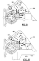
- An arrangement of the interlocking mechanism is illustrated in FIGS. 9-10.
- the interlocking mechanism is shown in the normal inoperative position in FIG. 10 and in the operative position in FIG. 9.
- Interlocking mechanism 202 includes an interlocking member 204 which is pivotally mounted on pivot pin 212 on nosepiece 22 and biased into the operative position by spring 206.
- Interlocking member 204 is normally retained in the inoperative position when the unitary movable structure is in the closed operative position by interlock engaging surface means in the form of a tab 208 which overcomes spring 206.
- Interlocking member 204 is moved into the operative position under the resilient bias of spring 206 when the unitary movable structure 32 is moved into the open loading position.
- leg portion 210 of interlocking member 204 is in the vertical upward travel path of the contact block 192 on the work contact responsive member 190 thus preventing work contact responsive member from being moved into the operative position.
- movement of the trigger member 196 is rendered ineffective to actuate the piston 20 and fastener driving element 38 due to the work contact responsive member being prevented from movement from the inoperative position into the operative position.
- resilient guard structure 16 disposed on the main drive portion 44 of the housing 12 and extending outwardly from the periphery thereof at least on opposite sides thereof.
- Mechanical structure is provided for detachably securing the resilient guard structure 16 to the housing 12, generally indicated at 230.
- resilient guard structure 16 includes a U-shaped member 232 which extends around the front and both sides of the housing 12 in groove 240 although it will be understood that separate members could be provided and secured only to the opposite sides of the main drive portion 44 which would provide support when the device 10 was placed down on an inclined roof surface when not in use.
- the mechanical structure 230 includes inwardly extending J-shaped hooks 234 fixedly embedded in the U-shaped member 232 on opposite sides thereof and to be brought into U-shaped receiving groove 242 in the housing 12 through which bolts 244 or the like which detachably fixedly mount a cap 246 on an open upper end of a drive portion 44 of the housing 12.
- U-shaped member 232 may be made of any elastomeric material although 80 durometer urethane is preferred. In order to securably attach the resilient guard structure 16 to the housing 12 it is necessary to stretch the U-shaped member 16 from a relaxed condition to a stretched condition so as to place each of the J-shaped hooks 234 into a corresponding U-shaped receiving groove 242 formed in the housing 12. It will be understood that the U-shaped member 232 serves as its own resilient bias for securing resilient guard structure 16 to the housing 12.
- U-shaped member 232 for reducing lateral and vertical movement thereof relative to the housing including a pair of projecting portions 236 extending inwardly from the U-shaped member 232 which are brought into cooperating engagement with a pair of grooves which extend inwardly from the periphery of the housing (not shown).
- the device 10 when not being used in portable fashion is capable of being selectively supported in either of two support positions on a support surface in which one side of the periphery of the housing main drive portion 44 faces toward the support surface with an area of corresponding outwardly facing surface of the resilient guard structure in engagement with the support surface.
- the area of engagement of the outwardly facing surface engaging the support surface and the coefficient of friction of the resilient material of the engaged outwardly facing surface area being such that the device will be stably supported in either support position on an inclined support surface, such as a roof surface, having an incline of 45° or less.
- the resilient guard structure 16 can be removed and a new one attached.
- a last nail holding means including magnetic means, generally indicated at 250, in the form of a magnet, means for dissipating air under pressure, generally indicated at 260, in the form of a fastener driving element 38 and a fastener driving element guide 258, and exhaust means, generally indicated at 252, in the form of an exhaust passageway 254.
- magnetic means 250 includes a cylindrical magnet 256 having a face disposed outside the drive track 26 but in communication therewith so as to attract the head of a the last nail moved into the drive track.
- the exhaust means 252 includes a passageway 254 which is formed between the drive track 26 and the atmosphere and extends therebetween. Passageway 254 is formed in fastener driving element guide 258 and through the nosepiece 22.
- Nail feeding means 58 in the form of a ratchet type fastener feeding mechanism is provided to feed the leading nails and the last nail of the array into the drive track 26.
- the feeding mechanism 58 is operatively located within the feed track 28 between the coil container 30 and the drive track 26.
- the feeding mechanism 58 is best understood first by reference to the feed track 28. As shown best in FIG. 2, one half of feed track 28 is formed by a feed track portion 280 of the housing 12 which extends rearwardly from the drive track 26 to the coil container 30 and is formed with a vertically extending surface 282 intersecting with the surface defining the drive track.
- the feed track portion is formed with a groove 284 which defines an upwardly facing inclined surface which is adapted to engage beneath the heads of the nails to support the same so that their shanks extend along vertical surface 282.
- a forward portion of the feed track portion is skeletonized or formed with lateral openings which create an elongated element 286 therebetween.
- the coil container 30 contains a selected nail coil that is manually engaged in operative relation with the feeding mechanism 58 by engaging the heads of the nails within the groove 284 and the shanks in engagement with surface 282.
- drive track door portion 64 contains a portion which forms the other half of the feed track when the unitary movable structure 32 is moved into the closed operative position.
- the nosepiece 22 has a cylinder 300 formed on the side opposite unitary movable structure 32 in laterally offset relation with respect to vertical surface 282.
- the cylinder includes a forward wall 302 apertured and sealed to sealingly receive therethrough an actuating rod 304.
- the interior of the cylinder 300 adjacent the forward wall 302 is communicated with a conventional plenum return assembly 42 of the fastener driving device 10, as by passageway 306 (see FIG. 14), so as to move a piston 308 fixed to the rearward end of the actuating rod 304 and slidably mounted within the cylinder 300 into a retracted position, such as shown in FIG. 16.
- the piston 308 and actuating rod 304 are moved forwardly from the retracted position, as shown in FIG. 16, into an extended position, as shown in FIG. 15, by a pair of coil springs 310 and 312.
- Coil spring 310 has one end engaged with piston 308 and the other end within a cap 314 mounted in the open rear end of the cylinder 300.
- Spring 312 has one end engaged with a forward portion of the piston and the other end engaged with the cap 314 and guided by spring guide 316.
- the actuating rod 304 extends forwardly and downwardly through the forward wall 302 of the cylinder 300 and has an aperture 318 formed in the forward portion thereof.
- a nail feeding member generally indicated at 320, is pivotally connected to actuating rod 304 by pivot pin 322 inserted into aperture 318 which serves to pivotally mount the nail feeding member on the actuating rod for movement therewith along and about its axis and for relative pivotal movement with respect to the actuating rod between a nail engaging position, as shown in FIGS. 15 and 16 and a nail clearing position.
- a compression spring 324 mounted between actuating rod 304 and nail feeding member 320 serves to resiliently bias the nail feeding member 320 into its nail engaging position and to resiliently resist movement out of such position into the nail clearing position thereof.
- the lateral surface of the nail feeding member is suitably recessed to receive the elongated element 286 of the nosepiece 22.
- Formed on the lateral surface of the nail feeding member 320 is a leading series of vertically spaced teeth 330, 332 and 334.
- a second series of vertically spaced teeth 336, 338 and 340 are formed in rearwardly spaced relation from the leading series of teeth.
- a third series of vertically spaced teeth 342, 344 and 346 are formed on the rearward lateral surface of the nail feeding member 320 in rearwardly spaced relation to the second series of teeth.
- the teeth of the leading series are formed with vertically aligned forwardly facing surfaces 348 which, when the nail feeding member 320 is in its nail engaging position and the actuating rod is its extended position, serves to close off a substantial portion of the area of communication between the drive track 26 and the feed track 28.
- the leading teeth also include rearwardly inclined cam surfaces 350.
- the second and third series of teeth include forwardly facing nail feeding surfaces 352 and 354, respectively, and rearward cam surfaces 356 and 358, respectively, and engaging the nail shanks and feeding same.
- Drive track door portion 64 of unitary movable structure 32 is formed with a central recess 370 opening into the feed track 28 within which is mounted a nail holding member or pawl 372.
- a pin 374 serves to mount the nail holding member for pivotal movement between a nail engaging position as shown in FIGS. 15 and 16, and a nail clearing position.
- the nail holding member 372 is resiliently biased into its nail engaging position by a coil spring 376 which extends between drive track door portion 64 and nail holding member 372 and serves to resiliently resist pivotal movement of the member 372 in a direction toward the nail clearing position thereof.
- Formed on the lateral forward surface of nail holding member is a first series of vertically spaced teeth 378 and 380.
- a second and third series of vertically spaced teeth, 382, 384 and 386, 388, respectively, are formed in rearwardly spaced relation from the first series.
- Each series of teeth include a forwardly facing nail holding surface 390, 392 and 394 respectively, and a rearwardly inclined cam surface 396, 398 and 400, respectively.
- FIG. 2 illustrates that the array of nails is supported in the feed track 28 by engagement of the lower surfaces of the heads with the upwardly facing surfaces of the grooves 284.
- Means for dissipating air 260 provides a path for exhaust air within the plenum chamber assembly 42 to flow to the atmosphere through exhaust passageway 254.
- the plenum chamber assembly 42 is of generally conventional design and includes a return air plenum chamber 418 defined by the interior periphery of the main drive portion 44 of the main casting below the flange 420 and the adjacent exterior periphery of the cylinder 18.
- the plenum chamber 418 communicates with the lower end of the cylinder 18 as by a plurality of circumferentially spaced openings 414 and 422 formed in the cylinder 18 at a position adjacent the lower end thereof.
- an annular resilient bumper member 412 Disposed within the lower end of the cylinder is an annular resilient bumper member 412 having its lower end seated in a mating surface at the bottom of cylinder 18.
- the fastener driving element guide 258 Centrally mounted below the cylinder 18 is the fastener driving element guide 258 which is apertured to receive the fastener driving element 38 therethrough.
- the aperture 424 provides a discharge passage for the return or exhaust air which exits from the cylinder 18.
- Fastener driving element 38 includes curved surfaces which form a close fitting relationship with apertured step 426 so as to restrict the discharge of return air therebetween during the fastener driving element return stroke when the air pressure within return air plenum chamber 418 has reached its maximum.
- the clearance between fastener driving element 38 and the driver guide 258 is greatly increased at the end of the return stroke where the driving element is positioned above the apertured step 426 so as to no longer be in close fitting relation therewith as shown best in Fig. 17. All remaining plenum air pressure can now rapidly escape through passages 254 and 428.
- the fastener driving element guide 258 is in closer fitting relation with the fastener driving element 38 during the drive and return stroke than at the end of the return stroke.
- the upper end of the bumper element is at approximately the same level as the openings 422 and is adapted to be engaged with the lower surface of the driving piston 20 when the latter reaches the end of its drive stroke.
- the plenum chamber 42 is charged with air under pressure from the cylinder 18 when the driving piston 20 passes the holes 414 to the end of its drive stroke where it contacts the bumper element 412.
- a plurality of circumferentially spaced openings 414 are formed in the cylinder 18 at a position approximately two-thirds the vertical distance of the drive stroke.
- an elastomeric annular check valve member 416 is located radially outwardly from the openings 414 so as to allow pressurized air within the cylinder 18 to flow into plenum chamber 42 when the pressure within the cylinder communicating therewith reaches a predetermined value.
- the trigger valve assembly 52 may assume any desired configuration. However, a preferred construction is in accordance with the teachings contained in commonly assigned U.S. Patent No. 5,083,694, the disclosure of which is hereby incorporated by reference into the present specification.
- the trigger valve assembly is resiliently biased into a normal inoperative position wherein a supply of air under pressure within hollow handle portion 14 of the housing 12 is enabled to pass through the trigger valve assembly 52 and into a passageway (not shown) which communicates with the pilot pressure chamber for main valve assembly 50.
- the pilot pressure chamber When the pilot pressure chamber is under pressure, the main valve assembly 50 is spring biased into a closed position as shown in FIG. 1.
- the main valve assembly 50 is pressure biased to move into an open position when the pressure in the pilot pressure chamber is relieved.
- the pilot pressure chamber is relieved when the actuating member 188 moves from an inoperative position to an operative position as described above.
- interlocking member 204 In response to the unitary movable structure 32 being moved from the closed operating position to the open loading position, interlocking member 204 will move from its inoperative position to the operative position thereby blocking the movement of contact trip element 190. It will be further understood that in the event that the contact trip element 190 is prevented from movement from the inoperative position into the operative position, movement of the trigger member 196 will be rendered ineffective to actuate the driving piston 20 and fastener driving element 38.
- the operator adjusts the support assembly of the coil container to accommodate the particular length of fastener contained within a coiled nail package which is to be loaded therein. Since the operator has complete access to the support assembly 130 it is a simple matter for the operator to drop the fastener package over the spindle 134 and to manually position the leading portion of the outer coil layer of the fastener package so that the heads of the nails therein are engaged within the groove 284 and the three leading nails are disposed within the ratchet type fastener feeding mechanism 58. After the fastener package has been suitably loaded into the device, the unitary movable structure 32 is moved into the closed operating position.
- the inlet fitting of the reservoir to the outlet fitting of a hose leading from a source of air under pressure.
- the entire air system within the device Prior to making this connection, the entire air system within the device is at atmospheric pressure.
- the source of air under pressure is connected with the reservoir 40, the pressure within the reservoir increases and this increase in pressure is immediately communicated with the pilot pressure chamber so as to maintain the spring biased pilot operated main valve assembly 50 in its closed position.
- the device 10 is now in condition to be actuated by the actuating member 188 which is moved into its operative position when contact trip element 190 is in its operative position when brought into engagement with a workpiece and the trigger member 196 is moved into its operative position in response to digital pressure being exerted thereon by the operator. As soon as the trigger member 196 is moved into its operative position, air within the pilot pressure chamber is allowed to be exhausted.
- the air under pressure within the reservoir 40 acting upwardly on the pilot operated main valve assembly 50 effects upward movement of the main valve assembly so as to communicate air under pressure within the reservoir 40 past the open main valve assembly 50 to the upper end of cylinder 18 which acts upon the upper surface of the driving piston 20 to effect a downward movement of the latter rapidly, from a first position, through its drive stroke.
- the fastener driving element 38 functions to drive a fastener within the drive track 26 outwardly thereof into a workpiece.
- the seal of the piston will pass the openings 414.
- the air under pressure acting on the upper surface of the piston passes through the openings 422, into the plenum chamber 418 and then the piston will engage the bumper element 412 as the drive stroke is completed.
- the trigger member 196 is then moved into its inoperative position either by the operator releasing the digital pressure on the trigger member 196 or by disengagement of the contact trip element 190 from the workpiece. In this manner, air under pressure from the reservoir 40 is communicated to the pilot pressure chamber which together with the spring returns the main valve assembly 50 to its closed position. This effects a communication path between the upper end of the cylinder 18 with the atmosphere through main valve assembly 50.
- the high pressure air within the plenum chamber 418 acting on the lower surface of the piston 20 through openings 422 effects a relatively rapid return stroke of the piston.
- the engagement of the piston 20 with the upper surface of the bumper element 412 serves to trap air so as to effect the aforesaid return stroke.
- the fastener drive element 38 is mounted with sufficient clearance with respect to fastener driving element guide 258 so that at the end of the return stroke the air under pressure effecting the return stroke of the piston dissipates to atmosphere so that when the piston reaches the upper end of its return stroke the air pressure in both the cylinder 18 as well as the plenum chamber 418 will be reduced to atmospheric pressure.
- FIG. 15 illustrates the position of the parts after a feed stroke has been accomplished and it will be noted that such a feed stroke will completed during the return stroke of the fastener driving element 38.
- the springs 312 and 314 are operable to move the actuating rod 304 from its retracted position, shown in FIG. 16 to its extended position, as shown in FIG. 15.
- the forwardly facing surfaces 348 of the leading teeth 330, 332 and 334 are disposed in a position to close a substantial portion of the area of communication between the drive track 26 and the feed track 28.
- Springs 312 and 314 serve to maintain the actuating rod 304 and nail feeding member 320 in their extended positions so that any attempt of the nail being driven to enter into the feed track 28 is resisted by the forwardly facing surface 348.
- the springs 312 and 314 does allow the surface 348 to move rearwardly in the rare event of extreme forces, such as might be associated with an inadvertent jam, thereby protecting the feed mechanism components from accelerated wear or damage.
- the cylinder 300 is pressurized to move the piston 308 and actuating rod 304 into its retracted position against the bias of springs 312 and 314.
- the nail feed member 320 is moved therewith likewise through a return stroke.
- the cam surfaces 350 of the leading teeth are in substantial engagement with the leading nail in the feed track 28 and during the return stroke the cam surfaces 350 serve to move the nails in the feed track 28 rearwardly until the leading nail in the feed track moves into engagement with the holding surface 390 of the nail holding member 372.
- the nail feeding member 320 When the nail feeding member 320 reaches either partly or entirely into its nail engaging position, the next three nails in the feed track 28 are immediately rearwardly of the cam surfaces 350, 356 and 358. As further movement takes place during the return stroke, the nail feeding member 320 is cammed into its nail clearing position by the action of cam surfaces 350, 356 and 358 engaging their respective nails which are held against rearward movement by the wires connecting the same to the leading nail and next two nails which are held against rearward movement by the wires connecting the same to the adjacent nail which is held by the nail holding member 372.
- the extent of the return stroke is such that the nail feeding surfaces 352 and 354 move past the second and third nails, respectively, and slightly rearwardly thereof as shown in FIG. 16.
- the engagement of the nail feeding surfaces 348, 352 and 354 with the second, third and fourth nails in the feed track 28 serves to move these nails forwardly and by virtue of the connecting wires, the leading nail likewise forwardly.
- the effect of this engagement is to pivot the nail holding member 372 out of its nail engaging position against the bias of the spring 376 after which the spring 376 serves to return the nail holding member 372 back into its nail engaging position.
- the completion of the feed stroke of the actuating rod 304 serves to move the leading nail into the drive track 26 as shown in FIG. 15, thus completing the cycle.
- nail feeding member 320 moves forwardly with sufficient force so as to thrust the last nail into the drive track 26 from the feed track 28 where the last nail will be supported by magnet 256.
- the feed stroke of nail feeding member 320 is completed during the return stroke of the fastener driving element 38 so that the last nail is being supported by the magnet at the end of the return stroke of the fastener feeding element 38.
- an exhaust passageway 254 permits the exhaust air to exit through this passageway without impinging on the last nail.
- the fastener driving element is in close fitting mating relationship with driving guide 258, providing reduced clearance so as to restrict exhaust airflow down through the drive track 26 during the drive and return stroke when the pressure is at its highest.
- the holding power of the magnet 256 and the force exerted by the exhaust air on the last nail is such that the last nail will be held in the drive track 26 until driven therefrom during the drive stroke of the fastener driving element 38.
- the resilient guard structure 16 will stably support the device 10 and prevent it from sliding on the pitched roof surface having an inclined surface of less than 45°.
Abstract
Description
- The present invention relates to a fastener driving device and in particular, but not exclusively, to a portable power-actuated fastener driving device.
- A common type of fastener package used in conjunction with portable power-actuated fastener driving devices is the coil fastener package. This fastener package is made up of a series of headed nails in a spaced parallel array interconnected by an elongated flexible carrier. Carriers come in several different forms. A well known one being a pair of parallel wires welded to the shanks of each nail in the array so as to maintain them in substantially parallel relation. With this arrangement, the portion of the wires which extend between each pair of adjacent parallel nails acts in effect like a parallel linkage.
- The utilization of nails of this type is highly desirable because larger numbers of nails are frequently packaged in coil formation. Fastener driving devices utilizing coiled nail packages typically include a feeding mechanism, a cylindrical container into which a new coiled nail package is placed, and a feed track therebetween. The feeding mechanism for coiled nail packages of the type described have heretofore been of the rachet type an example of which is disclosed in commonly assigned U.S. Patent No. 4,858,812 to Fealey. Because of the nature in which the successive nails are interconnected, it is important that the leading portion of the nail package be properly positioned within the drive track and engaged with the rachet feed mechanism. To assure proper positioning of the nails, operator access to the drive track, feed mechanism, feed track and coil container must be provided.
- Access is usually provided to each of the above mentioned members by multiple doors which permit the operator to load a new coiled nail package into the device. An advantage of multiple door construction is that each of the doors is relatively small, light, and close to its axis of rotation. This arrangement permits the device to be conveniently handled by the operator when reloading. However, problems are encountered with this type of arrangement. This arrangement requires the operator to typically use both hands to load the fastener package into the device. Thus, the device is generally placed down to enable the operator to load the device. Time is wasted in opening each door and in placing down the device. Further, the fabrication and assembly of multiple doors adds additional cost.
- One proposal to provide single door access is disclosed in U.S. Patent No. 4,600,135. The arrangement disclosed includes a single door that is pivotally movable about a vertical axis near the drive track. This arrangement has the advantage of permitting quick access for loading the device. However, this construction has a major drawback. Because of the large door size and the distance that the door extends horizontally from its vertical axis, the device becomes unbalanced when the door is fully opened making the device clumsy for an operator in use. Moreover, because of the distance that the door extends when pivoted from its vertical axis, enough room must be provided for the door to be fully opened.
- An object of the present invention is to provide single door access for a fastener driving device which obtains all of the advantages of the multiple and single door devices described above without the disadvantages of either. In accordance with the principles of the present invention, this objective is accomplished by providing a fastener driving device including a housing having a handle portion enabling a user to manually operate the device in portable fashion and a drive portion disposed forwardly of the handle portion. Power operated means are provided in the housing drive portion operable to be selectively moved through successive operating cycles each of which includes a drive stroke and a return stroke. A nosepiece and magazine assembly are carried by the housing including cooperating fixed and movable structure defining an elongated drive track, a feed track leading laterally into the drive track, and a coil container leading into the feed track. A fastener driving element is slidably mounted in the drive track and operatively connected with the drive means so as to drive a leading fastener fed into the drive track from the feed track outwardly of the drive track and into a workpiece during the drive stroke of the drive means. The nosepiece and magazine assembly include a unitary movable structure defining a side portion of the drive track, a side portion of the feed track and a side and top portion of the container. Means are provided for mounting the unitary movable structure for pivotal movement when a fastener package has been depleted from a closed operating position in cooperating relation with the fixed structure into an open loading position wherein (1) the drive track is accessible along the side portion defined by the movable structure so as to enable a leading fastener of a new fastener package to be positioned therein, (2) the feed track is accessible along the side portion defined by the movable structure so as to enable a leading portion of the array of the new fastener package to be positioned therein, and (3) the container is accessible along the side and top portions defined by the movable structure so as to enable the coil formation of the new fastener package to be positioned therein, and from the open loading position after a new package has been positioned as aforesaid into the closed operative position. A releasable latch is mounted for manual movement from an operative position retaining the movable structure in the closed operative position into a releasing position. The position of the pivotal axis of the unitary movable structure is such that when the device is held by the handle portion in a position such that a fastener would be moved out of the drive track in a substantial downward direction the movable structure will be moved by gravity from the closed operative position into the open loading position in response to the manual movement of the latch into the releasing position.
- It is highly desirable to be able to load the device with one hand while it is being held by the other, particularly, when the operator is using the device to fasten roof shingles to a roof surface. However, the roof environment is such that normal precautions in handling the device may be compromised somewhat. Consequently, where a device is to be particularly suited to on-roof use, it is further desirable to provide additional safeguards.
- Accordingly, another object of the invention is to provide a fastener driving device of the type described which provides such safeguards. In accordance with the principles of the present invention, this objective is obtained by providing an actuating mechanism for actuating the power operated drive means to move through an operating cycle. An actuation prevention mechanism is provided for preventing the actuation of the power operated means by the actuating mechanism in response to the movement of the movable structure from the closed operating position to the open loading position.
- A further problem is encountered with fastener driving devices of the type heretofore described when the device is used as a roofing nailer. Pitched roofs having inclined surfaces present the possibility of the device sliding off the roof due to gravity when the device is placed down on the roof because the device is not presently being used. Devices having exterior surfaces made of metal compound the problem by providing little frictional resistance which would prevent the device from sliding. Moreover, the sliding causes wear of the exterior surface of the housing. Thus, there is a need for a fastener driving device which is prevented from sliding when placed down on an inclined roof surface and which provides a wear surface.
- One proposal to provide a wear and impact surface is disclosed in U.S. Patent No. 5,085,126. The construction disclosed includes a rubber strip extending on both sides and across the cap of the housing and attached in surface engagement by an adhesive. This mode of securement results in either insufficient adherence or difficulties when it is desired to replace the rubber strip.
- Accordingly, another object of the present invention is to provide a fastener driving device of the type described which obviates the problems of location of the rubber strip and does not become loose in use in the manner set forth above. In accordance with the principles of the present invention, this objective is achieved by providing a resilient guard structure on opposite sides of the periphery of a main drive portion of the housing and extending outwardly therefrom. The resilient guard structure has outwardly facing surfaces disposed outwardly of the opposite sides of the periphery of the housing main drive portion. The device when not being used in portable fashion is capable of being selectively supported in either of two support positions on a support surface in which one side of the periphery of the housing main drive portion faces toward the support surface with an area of corresponding outwardly facing surface of the resilient guard structure in engagement with the support surface. Mechanical structure is provided for fixedly mounting the resilient guard structure on the main drive portion of the housing. The mechanical structure includes J-shaped hooks embedded in opposite ends of the resilient guard structure and extending outwardly thereof and bolts entering the J-shaped hooks. The bolts also serve to detachably fixedly mount a cap on an open upper end of a drive portion of the housing disposed forwardly of the handle portion thereof.
- While the resilient guard structure is shown in conjunction with a fastener driving device utilizing coiled nail packages, in its broadest aspects the present invention contemplates the utilization of this feature with any type of fastener driving device.
- A further problem is presented with fastener driving devices using fasteners of the type interconnected in an array by a pair of parallel wires attached to the shanks of each nail. In the ratchet mechanism heretofore described, it is the usual situation for the ratchet mechanism to feed off of the nail shank which is adjacent to the leading nail as shown in commonly assigned U.S. Patent Nos. 3,708,097 and 3,703,981. Typically, the leading nail which is disposed in the drive track is supported in the drive track by the wires which extend from the adjacent shank. This arrangement has the advantage of not having members protrude into the drive track. However, this arrangement does not provide support for the last nail. In devices which are capable of feeding the last nail into the drive track, the unsupported last nail can fall out of the drive track. In other devices, the last nail remains partially in the feed track which in the unsupported condition is prone to creating inadvertent jamming of the last nail when the operator attempts to drive the last nail from the device. One solution well known in the art is to prevent the actuation of the device when only a few fasteners remain in the feedtrack. This arrangement has the disadvantage of not utilizing all of the fasteners in the magazine.
- One type of nail feeding mechanism capable of feeding and supporting the last nail in the drive track is well known in the art. This type of mechanism embodies a nail feeding pawl provided with a surface for engaging the trailing shank surfaces of the leading nail in the nail feeding track. At the end of the nail feeding stroke of such a nail feeding pawl, the shank engaging surface thereof is disposed within the drive track at a position beneath the trailing portion of the circular head of the nail therein. Because of this relationship of the nail feeding pawl within the drive track, it is essential to provide for a rapid return stroke of the nail feeding pawl to prevent interengagement of the nail head therewith during the driving movement of the latter. Where air pressure is utilized as the means for effecting the return stroke of the nail feeding pawl, the rapidity at which the return stroke can be initiated tends to vary in accordance with source pressure. Thus, where lower source pressures are utilized or occur interferences tend to take place.
- Accordingly, another object of the present invention is to provide a fastener driving device of the type described in which the last nail can be driven from the drive track without having support members protruding into the drive track. In accordance with the principles of the present invention, this objective is achieved by providing pneumatic drive means which include a cylindrical drive chamber and a piston mounted within the drive chamber and operatively connected with the fastener driving element for movement through a drive stroke and a return stroke. A return air plenum chamber is provided for effecting the fastener driving element return stroke. Nail feeding means are mounted for movement only within the feed track so as to successively move the leading nails of the array into the drive track at the end of the return stroke. Last nail holding means are provided for retaining the last nail of the array within the drive track such that the last nail of the array is driven outwardly of the drive track and into a workpiece during the drive stroke of the fastener driving element. The last nail holding means includes a magnet mounted to said nosepiece and extending to the periphery of the drive track for receiving and holding the head of the last nail thrust into said drive track by said nail feeding means. Means are provided for dissipating the air under pressure within the plenum chamber which effects the return stroke of the piston which is exhausted through the drive track to the atmosphere at the end of the return stroke of the piston so that the last nail being held by the magnet is not blown off of the magnet by air exhausting the plenum chamber.
- Another object of the present invention is the provision of single door which provides access to the drive track, feed track and coil container in a fastener driving device utilizing coiled nail packages which is simple in construction, effective in operation and economical to manufacture.
- These and other objects of the present invention will become more apparent during the course of the following detailed description and appended claims.
- The invention is described further hereinafter, by way of example only, with refernce to the accompanying drawings in which:
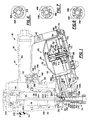
- FIG. 1 is a side elevational plan view of a fastener driving device constructed in accordance with the present invention shown partly in section for clarity, with the unitary movable structure shown in the closed operative position, with the housing and power operated means shown in dotted lines;
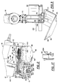
- FIG. 2 is a side elevational perspective view of the device of FIG. 1. with a fastener package loaded therein with the unitary movable structure shown in the open loading position;
- FIG. 3 is a rear elevational plan view, shown partly in section, with the unitary movable structure shown in the open loading position;
- FIG. 4 is a side elevational plan view shown partly in section, with a fastener package loaded therein with the unitary movable structure omitted for clarity;
- FIG. 5 is a side elevational plan view shown partly in section, with the unitary movable structure shown in the closed operative position;
- FIG. 6 is a cross-sectional view of the spindle taken along line 6-6 of FIG. 1;
- FIG. 7 is a cross-sectional view of the spindle taken along line 7-7 of FIG. 1;
- FIG. 8 is a cross-sectional view of the spindle taken along line 8-8 of FIG. 1;
- FIG. 9 is a top plan view of the interlocking member taken along line 9-9 of FIG. 14 with the unitary movable structure shown in the open loading position and the interlocking member in the operative position;
- FIG. 10 is a view similar to FIG. 9 with the unitary movable structure shown in the closed operative position and the interlocking member in the inoperative position;
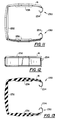
- FIG. 11 is a top plan view of the resilient guard structure constructed in accordance with the present invention;
- FIG. 12 is a side elevational view of the resilient guard structure of FIG. 11;
- FIG. 13 is a top plan sectional view of the resilient guard structure; FIG. 14 is a side elevational view showing the side opposite FIG. 1, shown partly in section for clarity;
- FIG. 14a is a cross-sectional view of the J-shaped hook of the resilient guard member and bolt taken along line 14a-14a of FIG. 14;
- FIG. 15 is a top sectional view taken along line 15-15 of FIG. 1 showing the actuating rod in its extended position;
- FIG. 16 is a top sectional view similar to FIG. 15 showing the actuating rod in its retracted position; and
- FIG. 17 is an enlarged side view, shown partly in section, showing the clearance between the fastener driving element and fastener driving element guide at the end of the return stroke of the fastener driving element.
- Referring now more particularly to FIG. 1 of the drawings, there is shown therein a portable pneumatically operated fastener driving device in the form of a portable tool, generally indicated at 10, which is constructed in accordance with the principles of the present invention. In the drawings, the device is shown oriented so as to drive a fastener vertically downwardly into a workpiece. It will be understood, however, that the device is capable of driving a fastener into workpieces oriented in any position other than the horizontal. For convenience, the device will be described in relation to the orientation illustrated, and consequently terms such as "horizontal," "vertical," "above," "below," "forward," "rearward," etc. as used herein are to be construed in their relative sense.
- As shown, the
device 10 includes a portable rigid housing assembly, generally indicated at 12, which provides ahandle portion 14. Attached to the periphery of the housing is a resilient guard structure, generally indicated at 16, embodying the principles of the present invention. In accordance with conventional practice, a drive chamber in the form of acylinder 18 is mounted within thehousing assembly 12, within which is slidably mounted adriving piston 20. Except when specifically required, although pneumatic systems are generally preferred, other systems either power or manually operable can be used, for effecting the cycle of operation of the fastener driving element may be utilized as, for example, electrical systems, spring actuated systems, hammer actuated systems, internal combustion systems and the like. - A
nosepiece 22 and magazine assembly, generally indicated at 24, are both carried by thehousing assembly 12 and together define therewith, a drive track, generally indicated at 26, a feed track, generally indicated at 28 and a coil container, generally indicated at 30. Thenosepiece 22 andmagazine assembly 24 include a unitary movable structure, generally indicated at 32 which is in cooperating relation with thehousing assembly 12. Means for mounting the unitary movable structure for pivotal movement is generally indicated at 34. Areleasable latch 36 is mounted on the unitarymovable structure 32 so as to secure the unitarymovable structure 32 into cooperating relation withhousing assembly 12. - A
fastener driving element 38 is fixed to thedriving piston 20 and extends within thedrive track 26. Means is provided within thehousing 12 to effect the return stroke of thepiston 20. For example, such means may be in the form of a conventional plenumchamber return system 42 such as disclosed in U.S. Patent No. 3,708,096, the disclosure of which is hereby incorporated by reference into the present specification. In accordance with conventional practice, thehandle portion 14 contains areservoir 40 for receiving a source of air under pressure which is communicated with the upper end of thecylinder 18 by a pilot pressure operatedmain valve assembly 50, within the main drive portion, generally indicated at 44, which is under the control of atrigger valve assembly 52 operated by a contact trip and triggerassembly 54, which together comprise part of theactuating mechanism 48, which function in accordance with conventional procedures although the actuation means may be of any known construction. An actuation prevention mechanism for preventing the actuation of the device operates in response to the unitary movable structure being moved from the closed operative position to the open loading position embodying the principles of the present invention and is generally indicated at 56. Nail feeding means in the form of a ratchet type fastener feeding mechanism, generally indicated at 58, is operable to cooperate with a leading end portion of a coiled fastener package array contained withincoil container 30. Last nail holding means for retaining the last nail of the array within thedrive track 26 is generally indicated at 60 embodying the principles of the present invention. - Likewise, the coiled fastener packages utilized with the tool may be of any known construction. The fastener package is preferably made up of a series of headed nails interconnected in an array by a pair of parallel wires welded to the shanks of each nail in the array so as to maintain them in substantially parallel relation. The wires are welded in angular relation (75°) across the parallel nail shanks. The array of nails is then wound into a spiraled coil formation in which the heads of convolutes are disposed in overlapped relation with respect to the heads of the preceding convolutes. It will be understood that the present invention contemplates selecting any one of a series of different nail sized coils.
- As described above and shown in Fig. 2, unitary
movable structure 32 together withhousing assembly 12 forms drivetrack 26,feed track 28, andcoil container 30. Unitarymovable structure 32 includes a feedtrack door portion 64 and acoil container portion 66 which are interlocked to one another which provides a rigid connection when mounted on the hinge assemblies as described below. Unitarymovable structure 32 is carried by thehousing assembly 12 by a forwardly mounted first hinge assembly, generally indicated at 70, and rearwardly mounted second hinge assembly, generally indicated at 72. As shown in Fig. 5, first hinge assembly includes a first pair of coaxial apertured lugs 74 attached to thehousing assembly 12 and disposed below thefeed track 28. A second pair of coaxial apertured lugs 76 are attached to the unitarymovable structure 32 and forwardly and rearwardly positioned from the first pair ofapertured lugs 74, respectively. Positioned rearwardly from both pairs ofapertured lugs apertured lug 78 attached to thecoil container portion 66 of the unitarymovable structure 32. Extending throughapertured lugs door pin 80 which is retained byplastic collars 82 or the like.Second hinge assembly 72 includes apivot pin 84 which extends throughholes 86 formed in the upwardly extendingperipheral wall portion 116 and base member 103 and retained therein bycross pin 88. As shown in Fig. 3,cross pin 88 has a shoulder portion 90 and is retained byplastic collar 92 or the like. - Referring now more particularly to FIGS. 1-3, the
magazine assembly 24 includes thecoil container 30. Thecoil container 30 includes abase member 102 of generally disc-shaped configuration having an innerperipheral flange 104 and acentral aperture 106 formed therein for receiving one end of ahollow spindle 108 secured to the central portion of the base member, by any suitable means, such as a retaining ring 110.Base member 102 is fixedly secured to thehousing assembly 12 by any suitable means such asbolts 112.Base member 102 has an upwardly extendingperipheral wall portion 116 having a semi-circular cross section which forms one half of the cylindrical portion of thecoil container 30. Thecoil container portion 66 of unitarymovable structure 32 forms the remainingcylindrical wall portion 118 of thecoil container 30 as best shown in FIG. 2 and also provides thecover 120 when moved into the closed operative position and thus provides peripheral confinement for the fastener package when the unitary movable structure is moved into the closed operative position. It should be noted that thecoil container 30 has a forwardly located vertical opening which opens into thefeed track 28 so as to allow fasteners to be moved from the coil container into the feed track. - Carried by the fixed
spindle 108 for movement into a plurality of adjusted positions with respect thereto, is a fastener package supporting assembly, generally indicated at 130. Theassembly 130 includes a movable disc-shapedfastener support member 132 which is attached to postmember 134 by any suitable means such as welding.Post member 134 is cylindrical in configuration and has a radially outwardly extendingflange portion 136 for supportingsupport member 132. - Secured to one end of the fixed
spindle 108 and an opposite end of thepost member 134 arespring receivers 138. Extending throughspindle 108 andpost member 134 is anextension spring 140 which is attached at opposite ends to the spring receivers and serves to resiliently bias the supporting assembly in a direction towardbase member 102. - Height adjustment of support member is provided for maintaining the
support assembly 130 in different spaced positions from thebase member 102 for the purpose of accommodating fastener packages of various sizes. As best shown in FIG. 1, such adjustment means comprises a plurality of vertically and angularly spaced pairs of slotted shoulders onspindle 108 and a pair oftabs 142 fixedly secured to postmember 134 and to be brought into vertical and rotational engagement with the spaced pairs of slottedshoulders support assembly 130 is adjusted to accommodate a small size fastener package, each of thetabs 142 extends into a slot as shown in FIGS. 1 and 6-8. When it is desired to accommodate a fastener package of a larger size, the operator grasps themovable post member 134 and pulls the same untilpost member 134 is brought out of engagement with that shoulder and is then rotated so as to engage a different slot and effect a different height adjustment. - Unitary movable structure also includes a drive
track door portion 64 which extends in the direction of extent of thedrive track 26 and forms a portion thereof. Drivetrack door portion 64 has a vertically extendingsegmental portion 150 in a forward portion thereof which forms a portion of thedrive track 26. - Mounted on drive
track door portion 64 is areleasable latch 36 which is mounted for manual movement from an operative position retaining the unitary movable structure in a closed operative position into a releasing position.Releasable latch 36 includes alatch body 160 and aslidable locking member 162 mounted for sliding movement therein which is normally biased into a latching position by aspring 164. Afinger engaging tab 166 extends outwardly therefrom enabling an operator to manually move lockingmember 162 into a releasing position. Acatch 168 inhousing assembly 12 receives lockingmember 162 so as to retain unitarymovable structure 32 in the closed operative position when the former is in the latching position. - It can thus be seen that since the unitary movable structure is mounted for pivotal movement when a fastener package has been depleted from a closed operating position in cooperating relation with the fixed structure into an open loading position wherein (1) the drive track is accessible along the side portion defined by the movable structure so as to enable a leading fastener of a new fastener package to be positioned therein, (2) the feed track is accessible along the side portion defined by the movable structure so as to enable a leading portion of the array of the new fastener package to be positioned therein, and (3) the container is accessible along the side and top portions defined by the movable structure so as to enable the coil formation of the new fastener package to be positioned therein, and from the open loading position after a new package has been positioned as aforesaid into the closed operative position.
- It should further be understood that the mass of the unitary
movable structure 32 is laterally disposed from thehinge assemblies handle portion 14 in a position such that a fastener would be moved out thedrive track 26 in a substantial downward direction the unitarymovable structure 32 will be moved by gravity into the open loading position from the closed operative position in response to the manual movement of thelatch 36 into the releasing position. - Referring now more particularly to FIGS. 9-10, the
device 10 includes an actuating prevention mechanism, generally indicated at 56, for preventing the actuation of the power operated means by theactuating mechanism 48, operates in response to the movement of themovable structure 32 from the closed operating position to the open loading position. It should be understood that while the preferred embodiment is shown in conjunction with a fastener driving device utilizing coiled nail packages and a pneumatic fastener driving means, in its broadest aspects the present invention could be used with any type of fastener driving device. As previously mentioned, atrigger valve assembly 52 controls the actuation of thepiston 20 through its fastener drive stroke. The trigger valve assembly includes a reciprocatively mounted depending actuatingmember 188 which controls the fluid pressure control system. Selective movement of the actuatingmember 188 from a normal outwardly extending inoperative position into an inwardly extending operative position initiates thedriving piston 20 to move through a fastener driving stroke. Theactuating mechanism 48 also includes acontact trip assembly 54 which includes acontact trip element 190 having a lower portion reciprocatively mounted in cooperating relationship with the nosepiece of the housing adjacent thedrive track 26, an intermediate portion extending rearwardly therefrom and an upper vertically extending portion upon which acontact block 192 is mounted by any suitable means such as welding. For purposes of the present application,contact trip element 190 may be considered a work contact responsive member. Thecontact trip element 190 is resiliently urged into a downward inoperative position by aspring 194 so that the lower end portion thereof extends beyond the discharge end of thedrive track 26. The work contactresponsive member 190 is movable from its normal inoperative position in response to the movement of thedevice 10 into cooperative engagement with a workpiece. Movement of the device away from the workpiece serves to effect movement of the work contactresponsive member 190 from its operative position back to its inoperative position under the action of thespring 194. - The
actuating mechanism 48 also includes aconventional trigger member 196 which is pivotally mounted from thehousing 12 and atrigger lever 198 pivotally mounted at 200 with thetrigger member 196. Thetrigger lever 198 is adapted to depress actuatingmember 188 into its operative position for actuating thepiston 20 andfastener driving element 38 as described heretofore. Thetrigger lever 198 is free to pivot at 200 so that movement of thetrigger member 196 alone into its operative position, without concomitant movement of work contactresponsive member 190 into its operative position, will be ineffective to move actuatingmember 188 into its operative position. - In accordance with the principles of the present invention, a means for preventing the power operated means to move through a fastener drive stroke is provided in the form of a contact trip interlocking mechanism, generally indicated at 202. An arrangement of the interlocking mechanism is illustrated in FIGS. 9-10. The interlocking mechanism is shown in the normal inoperative position in FIG. 10 and in the operative position in FIG. 9.
Interlocking mechanism 202 includes an interlockingmember 204 which is pivotally mounted onpivot pin 212 onnosepiece 22 and biased into the operative position byspring 206.Interlocking member 204 is normally retained in the inoperative position when the unitary movable structure is in the closed operative position by interlock engaging surface means in the form of atab 208 which overcomesspring 206.Interlocking member 204 is moved into the operative position under the resilient bias ofspring 206 when the unitarymovable structure 32 is moved into the open loading position. When in the operative position,leg portion 210 of interlockingmember 204 is in the vertical upward travel path of thecontact block 192 on the work contactresponsive member 190 thus preventing work contact responsive member from being moved into the operative position. It will be understood that movement of thetrigger member 196 is rendered ineffective to actuate thepiston 20 andfastener driving element 38 due to the work contact responsive member being prevented from movement from the inoperative position into the operative position. - Referring now more particularly to FIGS. 1, 11, 12, 13 and 14 and in accordance with the principles of the present invention there is shown a
resilient guard structure 16 disposed on themain drive portion 44 of thehousing 12 and extending outwardly from the periphery thereof at least on opposite sides thereof. Mechanical structure is provided for detachably securing theresilient guard structure 16 to thehousing 12, generally indicated at 230. As shown,resilient guard structure 16 includes aU-shaped member 232 which extends around the front and both sides of thehousing 12 in groove 240 although it will be understood that separate members could be provided and secured only to the opposite sides of themain drive portion 44 which would provide support when thedevice 10 was placed down on an inclined roof surface when not in use. Themechanical structure 230 includes inwardly extending J-shapedhooks 234 fixedly embedded in theU-shaped member 232 on opposite sides thereof and to be brought intoU-shaped receiving groove 242 in thehousing 12 through whichbolts 244 or the like which detachably fixedly mount acap 246 on an open upper end of adrive portion 44 of thehousing 12. -
U-shaped member 232 may be made of any elastomeric material although 80 durometer urethane is preferred. In order to securably attach theresilient guard structure 16 to thehousing 12 it is necessary to stretch theU-shaped member 16 from a relaxed condition to a stretched condition so as to place each of the J-shapedhooks 234 into a corresponding U-shaped receivinggroove 242 formed in thehousing 12. It will be understood that theU-shaped member 232 serves as its own resilient bias for securingresilient guard structure 16 to thehousing 12. Further, means are provided byU-shaped member 232 for reducing lateral and vertical movement thereof relative to the housing including a pair of projectingportions 236 extending inwardly from theU-shaped member 232 which are brought into cooperating engagement with a pair of grooves which extend inwardly from the periphery of the housing (not shown). - It should be understood that the
device 10 when not being used in portable fashion is capable of being selectively supported in either of two support positions on a support surface in which one side of the periphery of the housingmain drive portion 44 faces toward the support surface with an area of corresponding outwardly facing surface of the resilient guard structure in engagement with the support surface. The area of engagement of the outwardly facing surface engaging the support surface and the coefficient of friction of the resilient material of the engaged outwardly facing surface area being such that the device will be stably supported in either support position on an inclined support surface, such as a roof surface, having an incline of 45° or less. Further, when theU-shaped member 232 has worn to such an extent that it should be replaced so as to provide the features described heretofore, theresilient guard structure 16 can be removed and a new one attached. - Referring now more particularly to FIGS. 1, 4, 14-16 and in accordance with the principles of the present invention there is shown therein a last nail holding means, generally indicated at 60, including magnetic means, generally indicated at 250, in the form of a magnet, means for dissipating air under pressure, generally indicated at 260, in the form of a
fastener driving element 38 and a fastenerdriving element guide 258, and exhaust means, generally indicated at 252, in the form of anexhaust passageway 254. As shown in FIG. 1,magnetic means 250 includes acylindrical magnet 256 having a face disposed outside thedrive track 26 but in communication therewith so as to attract the head of a the last nail moved into the drive track. The exhaust means 252 includes apassageway 254 which is formed between thedrive track 26 and the atmosphere and extends therebetween.Passageway 254 is formed in fastener drivingelement guide 258 and through thenosepiece 22. - Nail feeding means 58 in the form of a ratchet type fastener feeding mechanism is provided to feed the leading nails and the last nail of the array into the
drive track 26. Thefeeding mechanism 58 is operatively located within thefeed track 28 between thecoil container 30 and thedrive track 26. Thefeeding mechanism 58 is best understood first by reference to thefeed track 28. As shown best in FIG. 2, one half offeed track 28 is formed by afeed track portion 280 of thehousing 12 which extends rearwardly from thedrive track 26 to thecoil container 30 and is formed with a vertically extendingsurface 282 intersecting with the surface defining the drive track. The feed track portion is formed with agroove 284 which defines an upwardly facing inclined surface which is adapted to engage beneath the heads of the nails to support the same so that their shanks extend alongvertical surface 282. A forward portion of the feed track portion is skeletonized or formed with lateral openings which create anelongated element 286 therebetween. It will be understood that thecoil container 30 contains a selected nail coil that is manually engaged in operative relation with thefeeding mechanism 58 by engaging the heads of the nails within thegroove 284 and the shanks in engagement withsurface 282. As previously described, drivetrack door portion 64 contains a portion which forms the other half of the feed track when the unitarymovable structure 32 is moved into the closed operative position. - As best shown in FIGS. 15 and 16, the
nosepiece 22 has acylinder 300 formed on the side opposite unitarymovable structure 32 in laterally offset relation with respect tovertical surface 282. The cylinder includes aforward wall 302 apertured and sealed to sealingly receive therethrough anactuating rod 304. - It will be noted that the interior of the
cylinder 300 adjacent theforward wall 302 is communicated with a conventional plenum return assembly 42 of thefastener driving device 10, as by passageway 306 (see FIG. 14), so as to move apiston 308 fixed to the rearward end of theactuating rod 304 and slidably mounted within thecylinder 300 into a retracted position, such as shown in FIG. 16. Thepiston 308 andactuating rod 304 are moved forwardly from the retracted position, as shown in FIG. 16, into an extended position, as shown in FIG. 15, by a pair ofcoil springs Coil spring 310 has one end engaged withpiston 308 and the other end within acap 314 mounted in the open rear end of thecylinder 300.Spring 312 has one end engaged with a forward portion of the piston and the other end engaged with thecap 314 and guided byspring guide 316. - The
actuating rod 304 extends forwardly and downwardly through theforward wall 302 of thecylinder 300 and has anaperture 318 formed in the forward portion thereof. A nail feeding member, generally indicated at 320, is pivotally connected to actuatingrod 304 bypivot pin 322 inserted intoaperture 318 which serves to pivotally mount the nail feeding member on the actuating rod for movement therewith along and about its axis and for relative pivotal movement with respect to the actuating rod between a nail engaging position, as shown in FIGS. 15 and 16 and a nail clearing position. Acompression spring 324 mounted betweenactuating rod 304 andnail feeding member 320 serves to resiliently bias thenail feeding member 320 into its nail engaging position and to resiliently resist movement out of such position into the nail clearing position thereof. - The lateral surface of the nail feeding member is suitably recessed to receive the
elongated element 286 of thenosepiece 22. Formed on the lateral surface of thenail feeding member 320 is a leading series of vertically spacedteeth teeth teeth nail feeding member 320 in rearwardly spaced relation to the second series of teeth. The teeth of the leading series are formed with vertically aligned forwardly facingsurfaces 348 which, when thenail feeding member 320 is in its nail engaging position and the actuating rod is its extended position, serves to close off a substantial portion of the area of communication between thedrive track 26 and thefeed track 28. The leading teeth also include rearwardly inclined cam surfaces 350. Similarly, the second and third series of teeth include forwardly facing nail feeding surfaces 352 and 354, respectively, and rearward cam surfaces 356 and 358, respectively, and engaging the nail shanks and feeding same. - Drive
track door portion 64 of unitarymovable structure 32 is formed with acentral recess 370 opening into thefeed track 28 within which is mounted a nail holding member orpawl 372. As shown, apin 374 serves to mount the nail holding member for pivotal movement between a nail engaging position as shown in FIGS. 15 and 16, and a nail clearing position. Thenail holding member 372 is resiliently biased into its nail engaging position by acoil spring 376 which extends between drivetrack door portion 64 andnail holding member 372 and serves to resiliently resist pivotal movement of themember 372 in a direction toward the nail clearing position thereof. Formed on the lateral forward surface of nail holding member is a first series of vertically spacedteeth nail holding surface inclined cam surface feed track 28 by engagement of the lower surfaces of the heads with the upwardly facing surfaces of thegrooves 284. - Means for dissipating air 260 provides a path for exhaust air within the
plenum chamber assembly 42 to flow to the atmosphere throughexhaust passageway 254. Referring now more particularly to FIG. 1, it will be noted that theplenum chamber assembly 42 is of generally conventional design and includes a returnair plenum chamber 418 defined by the interior periphery of themain drive portion 44 of the main casting below the flange 420 and the adjacent exterior periphery of thecylinder 18. Theplenum chamber 418 communicates with the lower end of thecylinder 18 as by a plurality of circumferentially spacedopenings 414 and 422 formed in thecylinder 18 at a position adjacent the lower end thereof. Disposed within the lower end of the cylinder is an annularresilient bumper member 412 having its lower end seated in a mating surface at the bottom ofcylinder 18. Centrally mounted below thecylinder 18 is the fastener drivingelement guide 258 which is apertured to receive thefastener driving element 38 therethrough. Theaperture 424, as best shown in FIG. 15, provides a discharge passage for the return or exhaust air which exits from thecylinder 18.Fastener driving element 38 includes curved surfaces which form a close fitting relationship withapertured step 426 so as to restrict the discharge of return air therebetween during the fastener driving element return stroke when the air pressure within returnair plenum chamber 418 has reached its maximum. The clearance betweenfastener driving element 38 and thedriver guide 258 is greatly increased at the end of the return stroke where the driving element is positioned above theapertured step 426 so as to no longer be in close fitting relation therewith as shown best in Fig. 17. All remaining plenum air pressure can now rapidly escape throughpassages element guide 258 is in closer fitting relation with thefastener driving element 38 during the drive and return stroke than at the end of the return stroke. The upper end of the bumper element is at approximately the same level as theopenings 422 and is adapted to be engaged with the lower surface of thedriving piston 20 when the latter reaches the end of its drive stroke. - The
plenum chamber 42 is charged with air under pressure from thecylinder 18 when thedriving piston 20 passes the holes 414 to the end of its drive stroke where it contacts thebumper element 412. To accomplish this function, a plurality of circumferentially spaced openings 414 are formed in thecylinder 18 at a position approximately two-thirds the vertical distance of the drive stroke. Additionally, an elastomeric annularcheck valve member 416 is located radially outwardly from the openings 414 so as to allow pressurized air within thecylinder 18 to flow intoplenum chamber 42 when the pressure within the cylinder communicating therewith reaches a predetermined value. - The
trigger valve assembly 52 may assume any desired configuration. However, a preferred construction is in accordance with the teachings contained in commonly assigned U.S. Patent No. 5,083,694, the disclosure of which is hereby incorporated by reference into the present specification. The trigger valve assembly is resiliently biased into a normal inoperative position wherein a supply of air under pressure withinhollow handle portion 14 of thehousing 12 is enabled to pass through thetrigger valve assembly 52 and into a passageway (not shown) which communicates with the pilot pressure chamber formain valve assembly 50. When the pilot pressure chamber is under pressure, themain valve assembly 50 is spring biased into a closed position as shown in FIG. 1. Themain valve assembly 50 is pressure biased to move into an open position when the pressure in the pilot pressure chamber is relieved. The pilot pressure chamber is relieved when the actuatingmember 188 moves from an inoperative position to an operative position as described above. - Before commencing operation, it is first necessary to load a fastener package into an operative position within the
coil container 30. To accomplish this, it is necessary initially to gain access to thecoil container 30,feed track 28,drive track 26 as well as the ratchet typefastener feeding mechanism 58. The operator gains such access simply by gripping lockingmember 162 and moving it generally downwardly from an operative condition in which the unitarymovable structure 32 is in a closed operative position into a releasing position. This downward movement releases the unitarymovable structure 32 and the unitary movable structure will then be moved by gravity into the open loading position. In response to the unitarymovable structure 32 being moved from the closed operating position to the open loading position, interlockingmember 204 will move from its inoperative position to the operative position thereby blocking the movement ofcontact trip element 190. It will be further understood that in the event that thecontact trip element 190 is prevented from movement from the inoperative position into the operative position, movement of thetrigger member 196 will be rendered ineffective to actuate thedriving piston 20 andfastener driving element 38. - To load a fastener package, after the last nail has been driven from the device, the operator adjusts the support assembly of the coil container to accommodate the particular length of fastener contained within a coiled nail package which is to be loaded therein. Since the operator has complete access to the
support assembly 130 it is a simple matter for the operator to drop the fastener package over thespindle 134 and to manually position the leading portion of the outer coil layer of the fastener package so that the heads of the nails therein are engaged within thegroove 284 and the three leading nails are disposed within the ratchet typefastener feeding mechanism 58. After the fastener package has been suitably loaded into the device, the unitarymovable structure 32 is moved into the closed operating position. - To commence the operation of the
device 10 it is then necessary to connect the inlet fitting of the reservoir to the outlet fitting of a hose leading from a source of air under pressure. Prior to making this connection, the entire air system within the device is at atmospheric pressure. When the source of air under pressure is connected with thereservoir 40, the pressure within the reservoir increases and this increase in pressure is immediately communicated with the pilot pressure chamber so as to maintain the spring biased pilot operatedmain valve assembly 50 in its closed position. - The
device 10 is now in condition to be actuated by the actuatingmember 188 which is moved into its operative position whencontact trip element 190 is in its operative position when brought into engagement with a workpiece and thetrigger member 196 is moved into its operative position in response to digital pressure being exerted thereon by the operator. As soon as thetrigger member 196 is moved into its operative position, air within the pilot pressure chamber is allowed to be exhausted. - As the air within the pilot pressure chamber is exhausted to atmosphere, the air under pressure within the
reservoir 40 acting upwardly on the pilot operatedmain valve assembly 50 effects upward movement of the main valve assembly so as to communicate air under pressure within thereservoir 40 past the openmain valve assembly 50 to the upper end ofcylinder 18 which acts upon the upper surface of thedriving piston 20 to effect a downward movement of the latter rapidly, from a first position, through its drive stroke. During the drive stroke, thefastener driving element 38 functions to drive a fastener within thedrive track 26 outwardly thereof into a workpiece. - As the
driving piston 20 approaches the end of its drive stroke, and a second position, the seal of the piston will pass the openings 414. The air under pressure acting on the upper surface of the piston passes through theopenings 422, into theplenum chamber 418 and then the piston will engage thebumper element 412 as the drive stroke is completed. Thetrigger member 196 is then moved into its inoperative position either by the operator releasing the digital pressure on thetrigger member 196 or by disengagement of thecontact trip element 190 from the workpiece. In this manner, air under pressure from thereservoir 40 is communicated to the pilot pressure chamber which together with the spring returns themain valve assembly 50 to its closed position. This effects a communication path between the upper end of thecylinder 18 with the atmosphere throughmain valve assembly 50. As air within thecylinder 18 is exhausted, the high pressure air within theplenum chamber 418 acting on the lower surface of thepiston 20 throughopenings 422 effects a relatively rapid return stroke of the piston. In this regard, it will be noted that the engagement of thepiston 20 with the upper surface of thebumper element 412 serves to trap air so as to effect the aforesaid return stroke. Thefastener drive element 38 is mounted with sufficient clearance with respect to fastener drivingelement guide 258 so that at the end of the return stroke the air under pressure effecting the return stroke of the piston dissipates to atmosphere so that when the piston reaches the upper end of its return stroke the air pressure in both thecylinder 18 as well as theplenum chamber 418 will be reduced to atmospheric pressure. - The operating cycle of the
feeding mechanism 58 is illustrated in FIGS. 15 and 16. FIG. 15 illustrates the position of the parts after a feed stroke has been accomplished and it will be noted that such a feed stroke will completed during the return stroke of thefastener driving element 38. As soon as the force exerted by the air pressure incylinder 300 onpiston 308 drops below the forces exerted bysprings springs actuating rod 304 from its retracted position, shown in FIG. 16 to its extended position, as shown in FIG. 15. It will be noted that the forwardly facingsurfaces 348 of the leadingteeth drive track 26 and thefeed track 28.Springs actuating rod 304 andnail feeding member 320 in their extended positions so that any attempt of the nail being driven to enter into thefeed track 28 is resisted by theforwardly facing surface 348. Thesprings surface 348 to move rearwardly in the rare event of extreme forces, such as might be associated with an inadvertent jam, thereby protecting the feed mechanism components from accelerated wear or damage. - At the end of the drive stroke of the
fastener driving element 38, thecylinder 300 is pressurized to move thepiston 308 andactuating rod 304 into its retracted position against the bias ofsprings actuating rod 304 takes place, thenail feed member 320 is moved therewith likewise through a return stroke. The cam surfaces 350 of the leading teeth are in substantial engagement with the leading nail in thefeed track 28 and during the return stroke the cam surfaces 350 serve to move the nails in thefeed track 28 rearwardly until the leading nail in the feed track moves into engagement with the holdingsurface 390 of thenail holding member 372. When this engagement takes place, the leading nail cannot move any further rearwardly and thus the further rearward movement of thenail feeding member 320 results in the cam surfaces 350 engaging the nail and effecting a pivotal movement of thenail holding member 320 against the bias ofspring 324 into its nail clearing position. - When the
nail feeding member 320 reaches either partly or entirely into its nail engaging position, the next three nails in thefeed track 28 are immediately rearwardly of the cam surfaces 350, 356 and 358. As further movement takes place during the return stroke, thenail feeding member 320 is cammed into its nail clearing position by the action of cam surfaces 350, 356 and 358 engaging their respective nails which are held against rearward movement by the wires connecting the same to the leading nail and next two nails which are held against rearward movement by the wires connecting the same to the adjacent nail which is held by thenail holding member 372. The extent of the return stroke is such that the nail feeding surfaces 352 and 354 move past the second and third nails, respectively, and slightly rearwardly thereof as shown in FIG. 16. During this movement, the engagement of the nail feeding surfaces 348, 352 and 354 with the second, third and fourth nails in thefeed track 28 serves to move these nails forwardly and by virtue of the connecting wires, the leading nail likewise forwardly. The effect of this engagement is to pivot thenail holding member 372 out of its nail engaging position against the bias of thespring 376 after which thespring 376 serves to return thenail holding member 372 back into its nail engaging position. Thereafter, the completion of the feed stroke of theactuating rod 304 serves to move the leading nail into thedrive track 26 as shown in FIG. 15, thus completing the cycle. - It should be noted that the last nail will be fed into the drive track by
nail feeding member 320, not by virtue of the connecting wires, but rather by the forward movement of forwardly facingsurface 348 into the nail clearing position.Nail feeding member 320 moves forwardly with sufficient force so as to thrust the last nail into thedrive track 26 from thefeed track 28 where the last nail will be supported bymagnet 256. As described heretofore, the feed stroke ofnail feeding member 320 is completed during the return stroke of thefastener driving element 38 so that the last nail is being supported by the magnet at the end of the return stroke of thefastener feeding element 38. At the end of the return stroke of the fastener feeding element, residual air in the plenum chamber and the air below the piston exhausts between thefastener feeding element 38 and thefastener driving guide 258. To prevent the exhaust air from blowing the last nail held by the magnet off of the magnet and out of thedrive track 26, anexhaust passageway 254 permits the exhaust air to exit through this passageway without impinging on the last nail. Furthermore, the fastener driving element is in close fitting mating relationship with drivingguide 258, providing reduced clearance so as to restrict exhaust airflow down through thedrive track 26 during the drive and return stroke when the pressure is at its highest. However, the holding power of themagnet 256 and the force exerted by the exhaust air on the last nail is such that the last nail will be held in thedrive track 26 until driven therefrom during the drive stroke of thefastener driving element 38. - Also, as described heretofore, if the device is not in use and is placed down on a pitched roof surface, the
resilient guard structure 16 will stably support thedevice 10 and prevent it from sliding on the pitched roof surface having an inclined surface of less than 45°. - It will thus be seen that the objects of this invention have been fully and effectively accomplished. We realize, however, that the foregoing preferred specific embodiments have been shown and described for the purpose of illustrating the functional instructional principles of this invention subject to change without departure from such principles. Therefore, this invention includes all modifications encompassed within the spirit and scope of the following claims.
Claims (38)
- A fastener driving device (10) for driving successive fasteners from a fastener package (130) of the type including an array of interconnected fasteners wound in a coil formation, said device (10) comprising a housing (12) including a handle portion (14) enabling a user to manually operate said device (10) in portable fashion and a drive portion (44) disposed forwardly of said handle portion; power operated drive means (20) in said housing drive portion operable to be selectively moved through successive operating cycles each of which includes a drive stroke and a return stroke; characterized by a nosepiece (22) and magazine assembly (24) carried by said housing (12) including cooperating fixed and movable structures defining an elongate drive track (26), a feed track (28) leading into said drive track (26), and a coil container (30) leading into said feed track (28); a fastener driving element (38) slidably mounted in said drive track (26) and operatively connected to said drive means (20) so as to drive a fastener fed into said drive track (26) from said feed track (28) outwardly of said drive track (26) and into a workpiece during the drive stroke of said drive means (20); said nosepiece (22) and magazine assembly (24) movable structure including a unitary movable structure (32) defining a side portion of said drive track (26), a side portion of said feed track (28) and a side and top portion of said coil container (30); said unitary movable structure (32) being mounted for pivotal movement, when a fastener package (130) has been depleted, from a closed operating position in cooperating relation with said fixed structure into an open loading position wherein said drive track (26) is accessible along the side portion defined by said unitary movable structure (32) so as to enable a leading fastener of a new fastener package (130) to be positioned therein, said feed track (28) is accessible along the side portion defined by said unitary movable structure (32) so as to enable a leading portion of the array of the new fastener package to be positioned therein, and said coil container (30) is accessible along the side and top portions defined by said unitary movable structure (32) so as to enable the coil formation of the new fastener package (130) to be positioned therein, and from said open loading position into said closed operative position after a new package (130) has been positioned as aforesaid; and a releasable latch (36) mounted for manual movement from an operative position retaining said unitary movable structure (32) in said closed operative position to a releasing position, the pivotal axis of said unitary movable structure (32) being such that, when said device is held by said handle portion (14) in a position such that a fastener would be moved out of said drive track (26) in a substantial downward direction, said unitary movable structure (32) is moved by gravity from said closed operative position into said open loading position in response to the manual movement of said latch (36) into said releasing position.
- A fastener driving device as claimed in claim 1, wherein said unitary movable structure (32) has a longitudinal axis extending generally in the direction of extent of said feed track (28) and is pivotably connected to said fixed structure along said longitudinal axis.
- A fastener driving device as claimed in claim 1 or 2, further comprising an actuating mechanism (48) for the actuation of said power operated drive means (20) to move through an operating cycle and an actuating prevention mechanism (202) for preventing the actuation of said power operated drive means by said actuating mechanism (48) in response to the movement of said unitary movable structure (32) from said closed operating position to said open loading position.
- A fastener driving device (10) for driving successive fasteners from a fastener package (130) of the type including an array of interconnected fasteners wound in a coil formation, said device (10) comprising a housing (12) including a handle portion (14) enabling a user to manually operate said device (10) in portable fashion and a drive portion (44) disposed forwardly of said handle portion (14); power operated means (20) in said housing drive portion (44) operable to be selectively moved through successive operating cycles each of which includes a drive stroke and a return stroke; characterised by a nosepiece (22) and magazine assembly (24) carried by said housing (12) including cooperating fixed and movable structures defining an elongate drive track (26), a feed track (28) leading into said drive track (26), and a coil container (30) leading into said feed track (28); a fastener driving element (38) slidably mounted in said drive track (26) and operatively connected to said drive means (20) so as to drive a fastener fed into said drive track (26) from said feed track (28) outwardly of said drive track (26) and into a workpiece during the drive stroke of said drive means (20); said nosepiece (22) and magazine assembly (24) movable structure including a unitary movable structure (32) defining a side portion of said drive track (26), a side portion of said feed track (28) and a side and top portion of said coil container (30); said unitary movable structure (32) having a longitudinal axis extending generally in the direction of extent of said feed track (28), said unitary movable structure (32) being pivotably connected to said fixed structure along said longitudinal axis and being movable, when a fastener package (130) has been depleted, from a closed operating position in cooperating relation with said fixed structure into an open loading position wherein said drive track (26) is accessible along the side portion defined by said unitary movable structure (32) so as to enable a leading fastener of a new fastener package (130) to be positioned therein, said feed track (28) is accessible along the side portion defined by said unitary movable structure (32) so as to enable a leading portion of the array of the new fastener package (130) to be positioned therein, and said container (30) is accessible along the side and top portions defined by said unitary movable structure so as to enable the coil formation of the new fastener package (130) to be positioned therein, and from said open loading position into said closed operative position after a new package (130) has been positioned as aforesaid; and a releasable latch (36) mounted for manual movement from an operative position retaining said unitary movable structure (32) in said closed operative position into a releasing position.
- A fastener driving device as claimed in claim 4, wherein the position of said longitudinal axis of said unitary movable structure (32) is such that when said device (10) is held by said handle portion (14) in a position such that a fastener would be moved out of said drive track (26) in a substantial downward direction said unitary movable structure (32) will be moved by gravity from said closed operative position into said open loading position in response to the manual movement of said latch (36) into said releasing position.
- A fastener driving device as claimed in claim 2, 4 or 5, wherein the centre of gravity of said unitary movable structure (32) in said closed operating position is laterally spaced from said longitudinal axis.
- A fastener driving device as claimed in claim 2, 4, 5 or 6, wherein the centre of gravity of said unitary movable structure (32) in said open loading position is disposed below said device (10).
- A fastener driving device as claimed in claim 2 or any one of claims 4 to 7, wherein said longitudinal axis of said unitary movable structure (32) is inclined relative to a horizontal plane when said handle portion (14) extends horizontally.
- A fastener driving device as claimed in claim 2 or any one of claims 4 to 8, wherein said unitary movable structure (32) includes a coil container portion (66) forming said side and top portions of said coil container and a drive track door portion (64) forming said side portion of said drive track (26) and said side portion of said feed track (28).
- A fastener driving device as claimed in claim 9, wherein said drive track door portion (64) and said coil container portion (66) each include hinge means (70, 72) which serve to effect the pivotal connection of said unitary movable structure (32) to said fixed structure.
- A fastener driving device as claimed in claim 9 or 10, wherein said releasable latch (36) is mounted on an outer portion of said drive track door portion (64) and is engageable with a catch portion (168) fixed to said fixed structure for releasably locking said unitary movable structure (32) in said closed operating position.
- A fastener driving device as claimed in claim 9, 10 or 11, wherein said releasable latch (36) is biased into said latching position by spring means (164) operatively connected between said releasable latch (36) and said drive track door portion (64), said releasable latch (36) includes a locking portion carried by said drive track door portion (64) for movement into a latching position within an opening in said catch portion (168) and a manually engageable portion (166) for enabling the locking portion (162) to be manually moved out of such latching position (162) into a release position, said catch portion (168) having a cam surface engageable with said locking portion (162) to retract said locking portion (162) into a position to enter said opening when said unitary movable structure (32) is moved from said open loading position into said closed operative position.
- A fastener driving device as claimed in any one of claims 4 to 12, wherein said coil container (30) includes a circular fastener support member (132) adapted to receive in the coil formation of the fastener package (130) disposed within said coil container (30), and means (142) to adjust the position of said fastener support member (132) along an axis perpendicular to the longitudinal extent of said feed track (28) to accommodate fastener packages (132) of different fastener dimensions.
- A fastener driving device (10) for driving successive fasteners from a fastener package (130) of the type including an array of interconnected fasteners wound in a coil formation comprising a housing (12) including a handle portion (14) enabling a user to manually operate said device (10) in portable fashion and a drive portion (44) disposed forwardly of said handle portion (12); power operated drive means (20) in said housing drive portion (44) actuatable to be moved through successive operating cycles each of which includes a drive stroke and a return stroke; characterised by a nosepiece (22) and magazine (24) assembly carried by said housing (12) including cooperating fixed and movable structures defining an elongated drive track (26), a feed track (28) leading into said drive track (26), and a coil container (30) leading into said feed track (28); a fastener driving element (38) slidably mounted in said drive track (26) and operatively connected to said drive means (20) so as to drive a fastener fed into said drive track (26) from said feed track (28) outwardly of said drive track (26) and into a workpiece during the drive stroke of said drive means (20); said nosepiece (22) and magazine assembly (24) movable structure defining a side portion of said drive track (26), a side portion of said feed track (28) and a side and top portion of said container (30); said movable structure (32) being mounted for movement, when a fastener package (130) has been depleted, from a closed operating position in cooperating relation with said fixed structure into an open loading position wherein said drive track (26) is accessible along the side portion defined by said movable structure (32) so as to enable a leading fastener of a new fastener package to be positioned therein, said feed track (28) is accessible along the side portion defined by said movable structure (32) so as to enable a leading portion of the array of the new fastener package (130) to be positioned therein, and said coil container (30) is accessible along the side and top portions defined by said movable structure (32) so as to enable the coil formation of the new fastener package (130) to be positioned therein, and from said open loading position into said closed operative position after a new package (130) has been positioned as aforesaid; an actuating mechanism (48) for actuating said power operated drive means (20) to move through an operating cycle; and an actuating prevention mechanism (202) for preventing the actuation of said power operated means (20) by said actuating mechanism (48) in response to the movement of said movable structure (32) from said closed operating position to said open loading position.
- A fastener driving device as claimed in claim 14, wherein said actuating mechanism (48) includes a contact trip element (190) mounted for movement adjacent said nosepiece (22) for movement from an inoperative position to an operative position when said nosepiece (22) is moved into engagement with a workpiece, and a trigger member (196) mounted on said housing (12) adjacent said handle portion (14) for movement by digital pressure from an inoperative position into an operative position.
- A fastener driving device as claimed in claim 15, wherein said actuating mechanism (48) includes an actuating member (188) carried by said housing (12) for movement from a normal inoperative position into an operative position for selectively actuating said power operated means (20) to move through an operating cycle in response to the movement of said contact trip element (190) and said trigger member (196) into their respective operative positions.
- A fastener driving device as claimed in claim 16, wherein said actuating mechanism (48) further includes a linkage operatively associated with said contact trip element (190), said trigger member (196) and said actuating member (188) for enabling movement of said trigger member (196) into its operative position when said contact trip element (190) is in its inoperative position without movement of said actuating member (188) into its operative position, enabling movement of said trigger member (196) into its operative position when said contact trip element (190) is in its operative position to effect movement of said actuating member (188) into its operative position, and enabling movement of said contact trip element (190) when said trigger member (196) is in its inoperative position without movement of said actuating member (188) into its operative position, said actuating prevention mechanism (202) including an interlocking member (204) mounted for movement in response to the movement of said movable structure (32) between the closed operating and open loading positions thereof between (a) a normal inoperative position enabling said contact trip element (190) to undertake the aforesaid movements when said movable structure (32) is in said closed operating position, and (b) an operative position preventing said contact trip element (190) from being moved into said operative position from said inoperative position when said movable structure (32) is in said open loading position.
- A fastener driving device as claimed in claim 17, wherein said actuation preventing mechanism (202) further includes interlock engaging surface means (208) fixed to said movable structure (32) and a spring (206) biasing said interlocking member (204) into said operative position.
- A fastener driving device as claimed in claim 18, wherein said contact trip element (190) is movable vertically between said inoperative position and said operative position with respect to said interlocking member (204) so as to define a travel path between said inoperative position and said operative position.
- A fastener driving device as claimed in claim 19, wherein said interlock engaging surface means (208) moves said interlocking member (204) into said inoperative position against the bias of said spring (206) when said movable structure (32) is moved into said closed operating position and said spring (206) urges said interlocking member (204) into said operative position in response to said movable structure (32) being moved into said inoperative position such that said interlocking member (204) is moved into the travel path thereby blocking said contact trip element (190) from moving from said inoperative position to said operative position.
- A fastener driving device (10) for use in installing roofs or the like comprising a housing (12) including a handle portion (14) enabling a user to manually operate said device in portable fashion, a main drive portion (44) disposed forwardly of said handle portion (14) and a nose portion (22) defining a fastener drive track (26) aligned with said drive portion; a fastener driving element (38) slidably mounted in said drive track (26); a fastener magazine assembly (24) for feeding successive fasteners laterally into said drive track (26); power operated drive means (20) actuatable to move said fastener driving element (38) through successive operating cycles each of which includes a drive stroke during which a fastener fed to said drive track (26) is driven outwardly thereof into a workpiece and a return stroke; said housing main drive portion (44) including a periphery having opposite sides; characterised by a resilient guard structure (16) provided on opposite sides of the periphery of said housing main drive portion (44) and extending outwardly therefrom, said resilient guard structure (16) having outwardly facing surfaces disposed outwardly of the opposite sides of the periphery of said housing main drive portion (44); said device (10) when not being used in portable fashion being capable of being selectively supported in either of two support positions on a support surface in which one side of the periphery of the housing main drive portion (44) faces toward the support surface with an area of the corresponding outwardly facing surface of the resilient guard structure (16) in engagement with the support surface; and a mechanical structure (230) for fixedly mounting said resilient guard structure (16); wherein said mechanical mounting structure (230) includes J-shaped (234) hooks embedded in opposite ends of said resilient guard structure (16) and extending outwardly thereof, and bolt means (244) are arranged to enter said J-shaped hooks (234) and serve to detachably secure a cap (246) on an open upper end of a drive portion (44) of said housing (12) disposed forwardly of the handle portion (14) thereof.
- A fastener driving device as claimed in claim 21, wherein said outwardly facing surfaces of the resilient guard structure (16) are made of elastomeric material.
- A fastener driving device as claimed in claim 21 or 22, wherein said resilient guard structure is U-shaped.
- A fastener driving device as claimed in claim 21, 22 or 23, wherein the area of engagement of the outwardly facing surface engaging the support surface and the coefficient of friction of the resilient material of the engaged outwardly facing surface area are such that the device (10) will be stably supported in either support position on an inclined support surface, such as a roof surface, having an incline of 45° or less.
- A fastener driving device as claimed in any one of claims 21 to 24, wherein said resilient guard structure (16) has a relaxed condition and a stretched attached condition and the entering of said bolt means (244) in said J-shaped hooks (234) attached to the resilient guard structure (16) requires that said resilient guard structure (16) is stretched from said relaxed condition into said stretched attached condition so as to place each of said J-shaped hooks (234) within a U-shaped receiving groove (242) formed in the periphery of the drive portion (44) of the housing (12).
- A fastener driving device as claimed in any one of claims 21 to 25, wherein said resilient guard structure (16) is disposed on opposite sides of said housing (12) in a direction generally parallel to said feed track (26).
- A fastener driving device as claimed in any one of claims 1 to 3 or 14 to 26, wherein said power operated drive means (20) is pneumatic and includes a cylindrical drive chamber (18) and a piston (20) mounted within said drive chamber (18) and operatively connected with said fastener driving element (38) for movement through a drive stroke and a return stroke.
- A fastener driving device as claimed in claim 27, further comprising means (42) within said housing (12) defining a return air plenum chamber for effecting said fastener driving element return stroke, fastener feeding means (58) mounted for movement only within said feed track (28) so as to successively move the fasteners of the array into said drive track (26) and to thrust the last fastener of the array into said drive track (26) at the end of said return stroke such that the last fastener moves into the drive track (26) under its own momentum, said cylindrical drive chamber (18) having one end arranged for communication with said plenum chamber (42) so that air under pressure in said plenum chamber (42) can effect the return stroke of said piston (20), last fastener holding means (256) for retaining the last fastener of the array within said drive track (26) such that the last fastener of the array is driven outwardly of said drive track (26) and into a workpiece during the drive stroke of said fastener driving element (38), said last fastener holding means (256) including a magnet mounted to said nosepiece (22) and extending to the periphery of said drive track (26) for receiving and holding the head of the last fastener when thrust into said drive track (26) by said fastener feeding means (58) and means (254) for dissipating the air under pressure within said plenum chamber (42) so that air under pressure within said plenum chamber (42) which effects the return stroke of said piston (20) is exhausted through said drive track (26) to atmosphere at the end of the return stroke of said piston (20) so that the last fastener being held by said magnet (256) is not blown off of said magnet (256) by air exhausting said plenum chamber (42).
- A fastener driving device as claimed in any one of claims 1 to 20, 27 or 28, further comprising a resilient guard structure (16) on opposite sides of the periphery of a main drive portion (44) of said housing (12) and extending outwardly therefrom, said resilient guard structure (16) having outwardly facing surfaces disposed outwardly of the opposite sides of the periphery of said housing main drive portion (44), said device when not being used in portable fashion being capable of being selectively supported in either of two support positions on a support surface in which one side of the periphery of the housing main drive portion (44) faces toward the support surface with an area of corresponding outwardly facing surface of the resilient guard structure (16) in engagement with the support surface, and a mechanical structure (230) for fixedly mounting said resilient guard structure (16) to said housing drive portion (44), said mechanical structure (230) including J-shaped hooks (234) embedded in opposite ends of said resilient guard structure (16) and extending outwardly thereof, and bolt means (244) are arranged to enter said J-shaped hooks (234) and serve to detachably secure a cap (246) on an open upper end of a drive portion (44) of said housing (12) disposed forwardly of the handle portion (14) thereof.
- A fastener driving device (10) for driving successive nail fasteners from an array of interconnected fasteners comprising a housing (12) including a handle portion (14) enabling a user to manually operate said device (10) in portable fashion; a nosepiece (22) having means defining an elongate drive track (26) and a magazine assembly (24) having means defining a nail feed track (28) which communicates with said drive track (26); a fastener driving element (38) slidably mounted within said drive track (26) for movement through a drive stroke to drive a fastener in said drive track (26) outwardly into a workpiece, and through a return stroke; characterised by means (42) within said housing defining a return air plenum chamber for effecting said fastener driving element return stroke; nail feeding means (58) mounted for movement only within said feed track (28) so as to successively move the leading nails of the array into said drive track (26) and to thrust the last nail of the array into said drive track (26) at the end of said return stroke; pneumatic drive means operable to move a piston (20) selectively through successive drive strokes and including a cylindrical drive chamber (18) having one end arranged for communication with said plenum chamber (42) so that air under pressure in said plenum chamber (42) can effect the return stroke of said piston (20); last nail holding means (256) for retaining the last nail of the array within said drive track (26) such that the last nail of the array is driven outwardly of said drive track (26) and into a workpiece during the drive stroke of said fastener driving element (38); said last nail holding means (256) including a magnet mounted to said nosepiece (22) and extending to the periphery of said drive track (26) for receiving and holding the head of the last nail when thrust into said drive track (26) by said nail feeding means (58) and means (254) for dissipating the air under pressure within said plenum chamber (42) so that air under pressure within said plenum chamber (42) which effects the return stroke of said piston (20) is exhausted through said drive track (26) to the atmosphere at the end of the return stroke of said piston (20) so that the last nail being held by said magnet (256) is not blown off of said magnet (256) by air exhausting said plenum chamber (42).
- A fastener driving device as claimed in claim 30, wherein said magnet (256) is cylindrical and has opposite faces one of which is in communication with said drive track (26).
- A fastener driving device as claimed in claim 30 or 31, wherein said nail feeding means (58) includes an actuating rod (304) having a longitudinal axis extending in the direction of extent of said feed track (28) for axial reciprocating movement from a retracted position in a direction toward said drive track (26) through a feed stroke into an extended position and from said extended position in a direction away from said drive track (26) through a return stroke into said retracted position, a nail feeding member (320) mounted on said actuating rod (304) for pivotal and axial reciprocating movements with said actuating rod (304) and for pivotal movement relative to said actuating rod (304) about an axis parallel to the extent of said drive track (26) in opposite directions, first spring means (324) for biasing said nail feeding member (320) to pivotally move with respect to said actuating member (304) in one direction into a nail engaging position and for resisting pivotal movement in the opposite direction into a nail clearing position, second spring means (312, 314) for effecting axial movement of said actuating rod (304) through its feed stroke and for resiliently resisting axial movement in a direction away from said drive track (26), power operated means (308) for effecting axial movement of said actuating rod (304) through its return stroke and for enabling said second spring means (312, 314) to effect the feed stroke thereof and to resiliently resist axial movement thereof in the direction away from said drive track (26) when said actuating rod (304) is in said extended position, a nail holding member (372) mounted for pivotal movement about an axis parallel with the extent of said drive track (26) in opposite directions, and third spring means (376) for biasing said nail holding member (372) to pivotally move in one direction into a nail holding position and for resiliently resisting movement in the opposite direction into a nail clearing position, said drive track (26) defining means including a discharge end, said feed track (28) defining means including operatively fixed head controlling surface means facing inwardly with respect to said drive track (26) in a direction away from the discharge end thereof for engaging the nail heads and supporting the nails in the feed track (28), said nail feeding member (320) having a leading series of teeth (378, 380) aligned and spaced apart in the direction of extent of drive track (26), a second series of teeth (382, 384) aligned and spaced apart in the direction of extent of said drive track (26) spaced apart from said leading series of teeth (378, 380) in the direction of extent of said feed track (28) and a third series of teeth (386, 388) aligned and spaced apart from said second series of teeth (382, 384) in the direction of extent of said feed track (28), said second and third series of teeth (382, 384; 386, 388) each having feed surface means facing toward said drive track (26) for engaging a nail shank in said feed track (28) and successively moving the nails in said feed track (28) into said drive track (26) during the feed stroke of said actuating rod (304) when said nail feeding member (320) is in said nail engaging position, said nail holding member (372) having cam surface means (396, 398, 400) operable during the feed stroke of said actuating rod (304) to be engaged by a moving nail shank to initially effect a pivotal movement of said nail holding member in said opposite direction against the resilient resistance of said third spring means (376) into said nail clearing position and thereafter to allow a pivotal movement of said holding member (372) in said one direction under the bias of said third spring means (376) into said nail holding position, said nail holding member (392) having nail holding surface means (396, 398, 400) facing in a direction toward said drive track (26) for engaging a nail shank when said nail holding member (372) is in said nail holding position, said teeth (378, 380; 382, 384; 386, 388) having cam surface means operable during the return stroke of said actuating rod (304) to initially effect pivotal movement of said nail feeding member (320) by engagement with a nail shank in said opposite direction into said nail clearing position and to thereafter allow said first spring means (324) to effect pivotal movement of said nail feeding member (320) in said one direction into said nail engaging position.
- A fastener driving device as claimed in claim 32, wherein said nosepiece (22) and magazine assembly (24) include cooperating fixed and movable (32) structures defining said elongate drive track (26), said feed track (28), and a coil container (30) leading into said feed track.
- A fastener driving device as claimed in claim 32 or 33, wherein said nail holding member (372) is pivoted on said movable structure (32) and said third spring means (376) is mounted between said movable member and said nail holding member (372).
- A fastener driving device as claimed in any one of claims 30 to 34, wherein said means for dissipating air includes said fastener driving element (38) and a fastener guide member (258) disposed in said drive track (26), said fastener driving element guide member (258) having an aperture therethrough for slidably receiving said fastener driving element (38) in close fitting relation thereto.
- A fastener driving device as claimed in claim 35, wherein said fastener driving element guide member (258) and said fastener driving element (38) are arranged to be in closer fitting relation at the beginning of said return stroke than at the end of said return stroke.
- A fastener driving device as claimed in any one of claims 30 to 36, wherein said means for dissipating air is disposed between said cylindrical chamber (18) and the nail moved into said drive track (26).
- A fastener driving device as claimed in claim 37, wherein said means for dissipating air further includes an opening formed in said housing (12) and an opening formed in said fastener guide element (258) in communication with said opening in said housing (12), said openings forming a passageway extending between said drive track (26) and atmosphere.
Applications Claiming Priority (2)
| Application Number | Priority Date | Filing Date | Title |
|---|---|---|---|
| US6094693A | 1993-05-13 | 1993-05-13 | |
| US60946 | 1993-05-13 |
Publications (3)
| Publication Number | Publication Date |
|---|---|
| EP0644020A2 true EP0644020A2 (en) | 1995-03-22 |
| EP0644020A3 EP0644020A3 (en) | 1996-07-10 |
| EP0644020B1 EP0644020B1 (en) | 2001-08-16 |
Family
ID=22032726
Family Applications (1)
| Application Number | Title | Priority Date | Filing Date |
|---|---|---|---|
| EP94303456A Expired - Lifetime EP0644020B1 (en) | 1993-05-13 | 1994-05-13 | Fastener driving device |
Country Status (7)
| Country | Link |
|---|---|
| US (1) | US5683024A (en) |
| EP (1) | EP0644020B1 (en) |
| JP (1) | JPH07136942A (en) |
| AT (1) | ATE204221T1 (en) |
| AU (1) | AU667162B2 (en) |
| CA (1) | CA2121717A1 (en) |
| DE (1) | DE69427943T2 (en) |
Cited By (7)
| Publication number | Priority date | Publication date | Assignee | Title |
|---|---|---|---|---|
| WO1996039280A1 (en) * | 1995-06-05 | 1996-12-12 | Senco Products, Inc. | Fastener length adjustable canister-type magazine for a fastener driving tool |
| EP0938953A2 (en) * | 1998-02-27 | 1999-09-01 | Temar S.r.l. | Magazine for compressed-air nail firing tool |
| WO2002014027A2 (en) * | 2000-08-11 | 2002-02-21 | Stanley Fastening Systems, L.P. | Feed system for nailer |
| US6499643B1 (en) | 1998-09-18 | 2002-12-31 | Stanley Fastenening Systems, L.P. | Drive channel for nailer |
| US6672498B2 (en) | 1999-09-17 | 2004-01-06 | Stanley Fastening Sytems Lp | Feed system for nailer |
| WO2005011922A1 (en) * | 2003-07-30 | 2005-02-10 | Stanley Fastening Systems, L.P. | Integrated check pawl, last nail-retaining, and dry fire lock-out mechanism for fastener-driving tool. |
| EP1702722A1 (en) * | 2005-03-16 | 2006-09-20 | Black & Decker, Inc. | Coil nail spreader |
Families Citing this family (65)
| Publication number | Priority date | Publication date | Assignee | Title |
|---|---|---|---|---|
| JPH08141934A (en) * | 1994-11-14 | 1996-06-04 | Max Co Ltd | Nail guide device of nailing machine |
| JP3606962B2 (en) * | 1995-10-24 | 2005-01-05 | 株式会社マキタ | Fixing tool feeder for driving tool |
| US5850961A (en) * | 1997-01-07 | 1998-12-22 | Stanley-Bostitch, Inc. | Quick exhaust remote trigger valve for fastener driving tool |
| US5862969A (en) * | 1997-09-17 | 1999-01-26 | De Poan Pneumatic Corporation | Safety trigger for nailer |
| EP0987086A3 (en) * | 1998-09-18 | 2000-12-20 | Ramset Fasteners (Aust.) Pty. Ltd. | Power actuated tools with magazine feed |
| US6095393A (en) * | 1998-11-06 | 2000-08-01 | Illinois Tool Works Inc. | Fastener-driving tool having magazine mounted to tool handle by mortise and tenon mounting |
| US6126057A (en) * | 1999-02-26 | 2000-10-03 | Li; Ming Chu | Magazine structure for nailing machines |
| US6152346A (en) * | 1999-05-24 | 2000-11-28 | Illinois Tool Work Inc. | Adjustable magazines for nail tools and methods therefor |
| US6454151B1 (en) * | 2000-07-17 | 2002-09-24 | Lin Wang-Kuan | Power stapler |
| US6641019B2 (en) * | 2000-07-28 | 2003-11-04 | Robert Hadfield | Fastener driving tool with multi-size fastener magazine |
| US6431428B1 (en) * | 2000-10-16 | 2002-08-13 | Jui-Chin Chen | Pneumatic nail gun |
| JP2002200575A (en) * | 2000-12-28 | 2002-07-16 | Nisca Corp | Staple cartridge and stapler provided with the same |
| US7021511B2 (en) | 2002-09-18 | 2006-04-04 | Illinois Tool Works Inc. | Lock-out mechanism for powder actuated tool |
| US20050001007A1 (en) * | 2003-05-29 | 2005-01-06 | Butzen Robert W. | Pneumatic nailer |
| JP4239731B2 (en) * | 2003-07-04 | 2009-03-18 | マックス株式会社 | Contact mechanism of power driven nailer |
| US20060108391A1 (en) * | 2003-12-31 | 2006-05-25 | Leasure Jeremy D | Pneumatic fastener |
| ES2337375T3 (en) * | 2004-04-06 | 2010-04-23 | Cetram Pty Limited | ADAPTER FOR A TOOL. |
| US7699201B2 (en) * | 2004-05-25 | 2010-04-20 | Black & Decker Inc. | Fastening tool with automatic feeding of wire-collated fasteners |
| US8172118B2 (en) * | 2004-05-25 | 2012-05-08 | Black & Decker Inc. | Height adjustable coil nail canister |
| US6948647B1 (en) * | 2004-05-25 | 2005-09-27 | Black & Decker Inc. | Anti-slip shingle grip for fastening tool |
| US7137186B2 (en) * | 2004-12-03 | 2006-11-21 | Black & Decker Inc. | Magazine for wired-collated fasteners with automatic loading |
| US7866521B2 (en) | 2004-12-03 | 2011-01-11 | Black & Decker Inc. | Magazine for wired-collated fasteners with automatic loading |
| US7086573B1 (en) * | 2005-01-28 | 2006-08-08 | De Poan Pneumatic | Brake device for de-actuating a nail driver without nails therein |
| US7225962B2 (en) * | 2005-02-18 | 2007-06-05 | Illinois Tool Works Inc. | Nail advancement systems for nail arrays disposed within nailing tool magazines |
| US7328826B2 (en) | 2005-03-28 | 2008-02-12 | Illinois Tool Works Inc. | Power nailer with driver blade blocking mechanism magazine |
| US20060261128A1 (en) * | 2005-05-17 | 2006-11-23 | Ming-Han Wen | Pressing tongue for nails in the magazine for nail gun |
| WO2007002542A2 (en) * | 2005-06-24 | 2007-01-04 | James Murtha | Nail gun cartridge and driver and stud finder integrated with nail gun |
| US20070090148A1 (en) * | 2005-10-20 | 2007-04-26 | Jeil Tacker Co., Ltd. | Coil nailer for construction finish material |
| US7234623B2 (en) * | 2005-10-20 | 2007-06-26 | Testo Industry Corp. | Coil-type magazine for nail gun |
| US7232051B2 (en) * | 2005-10-21 | 2007-06-19 | Basso Industry Corp. | Nail tray hoist structure for a coil nailer |
| TWI311517B (en) * | 2006-01-24 | 2009-07-01 | Basso Ind Corp | Nail box device for a nailer |
| TW200734130A (en) * | 2006-03-03 | 2007-09-16 | Basso Ind Corp | A nail-pressing cover for nail gun |
| US7617883B1 (en) * | 2006-05-04 | 2009-11-17 | Mangone Jr Peter G | Fastening devices, method of manufacture, tool, and method of use |
| US20070267458A1 (en) * | 2006-05-22 | 2007-11-22 | Mu-Yu Chen | Pneumatic nail gun |
| DE102006035370A1 (en) * | 2006-10-27 | 2008-04-30 | Hilti Ag | Hand-operated tacker for driving e.g. nail, in workpiece, has pressing unit provided with spring unit, whose spring force is changeable to vector of gravitational force depending on spatial orientation of pressing unit |
| US7537145B2 (en) | 2007-02-01 | 2009-05-26 | Black & Decker Inc. | Multistage solenoid fastening device |
| US8276798B2 (en) | 2007-06-21 | 2012-10-02 | Illinois Tool Works Inc. | Feeder mechanism retention device for fastener driving tool |
| JP2009023063A (en) * | 2007-07-23 | 2009-02-05 | Kikkona Kk | Nail driving machine and construction method of wall heat-insulation structure |
| US7575140B2 (en) * | 2007-09-28 | 2009-08-18 | De Poan Pneumatic Corp. | Abutment adjusting device for nail gun |
| US8104658B2 (en) * | 2007-11-20 | 2012-01-31 | De Poan Pneumatic Corp. | Block device for nail gun |
| US7617959B2 (en) * | 2008-01-29 | 2009-11-17 | Testo Industry Corp. | Adjusting device for a nail gun |
| US20100001034A1 (en) * | 2008-07-07 | 2010-01-07 | Chun-Ming Huang | Loading device of a pneumatic nail gun |
| US20110049215A1 (en) * | 2009-08-26 | 2011-03-03 | Mcafee Ronald | Unpowered coil nailer |
| US8746526B2 (en) * | 2009-09-15 | 2014-06-10 | Robert Bosch Gmbh | Fastener driver with blank fire lockout |
| FR2953751B1 (en) * | 2009-12-11 | 2012-01-20 | Prospection & Inventions | FASTENING TOOL WITH ADJUSTABLE MASSELOTTE ROD EXTENSION |
| US9827658B2 (en) | 2012-05-31 | 2017-11-28 | Black & Decker Inc. | Power tool having latched pusher assembly |
| US11229995B2 (en) | 2012-05-31 | 2022-01-25 | Black Decker Inc. | Fastening tool nail stop |
| US9636811B2 (en) | 2013-03-11 | 2017-05-02 | Illinois Tool Works Inc. | Actuation lockout for a fastener-driving tool |
| JP6244696B2 (en) * | 2013-07-04 | 2017-12-13 | マックス株式会社 | Fastener driving tool |
| CA3146951A1 (en) | 2014-03-27 | 2015-10-01 | Techtronic Power Tools Technology Limited | Powered fastener driver and operating method thereof |
| CN103950009B (en) * | 2014-04-02 | 2016-02-03 | 闫强 | Folder code rifle |
| CN208289826U (en) | 2015-02-06 | 2018-12-28 | 米沃奇电动工具公司 | Using gas spring as the fastener driver of power |
| WO2017196825A1 (en) * | 2016-05-10 | 2017-11-16 | Omg, Inc. | Handheld fastener installation guide |
| CA2969392C (en) | 2016-06-08 | 2022-11-22 | Tti (Macao Commercial Offshore) Limited | Gas spring fastener driver |
| US11400574B2 (en) | 2016-06-21 | 2022-08-02 | Techtronic Power Tools Technology Limited | Gas spring fastener driver |
| US10569403B2 (en) | 2016-06-21 | 2020-02-25 | Tti (Macao Commercial Offshore) Limited | Gas spring fastener driver |
| US11325235B2 (en) | 2016-06-28 | 2022-05-10 | Black & Decker, Inc. | Push-on support member for fastening tools |
| US11267114B2 (en) | 2016-06-29 | 2022-03-08 | Black & Decker, Inc. | Single-motion magazine retention for fastening tools |
| US11279013B2 (en) | 2016-06-30 | 2022-03-22 | Black & Decker, Inc. | Driver rebound plate for a fastening tool |
| US11400572B2 (en) | 2016-06-30 | 2022-08-02 | Black & Decker, Inc. | Dry-fire bypass for a fastening tool |
| US10987790B2 (en) | 2016-06-30 | 2021-04-27 | Black & Decker Inc. | Cordless concrete nailer with improved power take-off mechanism |
| US10926385B2 (en) * | 2017-02-24 | 2021-02-23 | Black & Decker, Inc. | Contact trip having magnetic filter |
| WO2019199605A1 (en) | 2018-04-13 | 2019-10-17 | Milwaukee Electric Tool Corporation | Pusher mechanism for powered fastener driver |
| EP4126461A1 (en) | 2020-03-25 | 2023-02-08 | Milwaukee Electric Tool Corporation | Powered fastener driver |
| EP4146435A1 (en) | 2020-05-06 | 2023-03-15 | Milwaukee Electric Tool Corporation | Pusher mechanism for powered fastener driver |
Citations (17)
| Publication number | Priority date | Publication date | Assignee | Title |
|---|---|---|---|---|
| US2927324A (en) * | 1956-08-23 | 1960-03-08 | First Bank Of Grantsburg | Power nail driving tool |
| US3491932A (en) * | 1967-04-21 | 1970-01-27 | Fastener Corp | Fastener driving tool |
| GB1206948A (en) * | 1966-12-07 | 1970-09-30 | Gaston E Marbaix Ltd | Improvements in or relating to nail and like magazines for fastener driving tools |
| US3945551A (en) * | 1969-11-10 | 1976-03-23 | Max Kabushiki Kaisha | Nailing machine |
| EP0008749A1 (en) * | 1978-09-01 | 1980-03-19 | Karl M. Reich, Maschinenfabrik GmbH | Fastener-driving apparatus |
| US4375867A (en) * | 1978-07-05 | 1983-03-08 | Duo-Fast Corporation | Electric fastener driving tool |
| US4389012A (en) * | 1981-04-22 | 1983-06-21 | Duo-Fast Corporation | Fastener tool loading assembly |
| DE3224089A1 (en) * | 1982-06-29 | 1983-12-29 | Karl M. Reich Maschinenfabrik GmbH, 7440 Nürtingen | Round magazine for fastener driving-in tools |
| US4433782A (en) * | 1981-10-20 | 1984-02-28 | Sigma Tool & Machine Limited | Magazine assembly for coil nails |
| GB2151176A (en) * | 1983-11-07 | 1985-07-17 | Umberto Monacelli | Fastener feeding arrangements and driving apparatus |
| EP0169172A2 (en) * | 1984-07-16 | 1986-01-22 | HILTI Aktiengesellschaft | Driving tool for fastening elements, such as nails, staples etc. |
| US4600135A (en) * | 1983-12-29 | 1986-07-15 | Makita Electric Works, Ltd. | Nail driving tool |
| EP0218778A1 (en) * | 1985-06-21 | 1987-04-22 | Signode Corporation | Portable fastener driving tool |
| US4858812A (en) * | 1988-06-28 | 1989-08-22 | Stanley-Bostitch, Inc. | Nail driving device with improved nail feeding mechanism |
| EP0360573A2 (en) * | 1988-09-23 | 1990-03-28 | Illinois Tool Works Inc. | Fastener-driving tool |
| DE9106241U1 (en) * | 1991-05-21 | 1991-09-05 | Schmid, Juergen, 7403 Ammerbuch, De | |
| US5085126A (en) * | 1990-01-10 | 1992-02-04 | Makita Electric Works, Ltd. | Pneumatic percussion tool with relatively movable head valves |
Family Cites Families (11)
| Publication number | Priority date | Publication date | Assignee | Title |
|---|---|---|---|---|
| US2714208A (en) * | 1953-11-20 | 1955-08-02 | Bostitch Inc | Stapling implement |
| US3703981A (en) * | 1971-03-18 | 1972-11-28 | Textron Inc | Mechanism for containing a nail package and feeding successive nails therefrom |
| US3708097A (en) * | 1971-03-18 | 1973-01-02 | Textron Inc | Nail feed mechanism |
| US3708096A (en) * | 1971-04-28 | 1973-01-02 | Textron Inc | Pneumatically actuated fastener driving device with improved piston return air system |
| US4597518A (en) * | 1985-05-06 | 1986-07-01 | Bostitch Division Of Textron Inc. | Stapler with improved magazine cover construction |
| US4981247A (en) * | 1989-07-17 | 1991-01-01 | Richard C. Noll | Protective cover for an electric stapler |
| US5025970A (en) * | 1990-03-20 | 1991-06-25 | National Carpet Equipment Inc. | Protective sleeve for carpet tacking gun |
| DE9016493U1 (en) * | 1990-12-05 | 1991-03-14 | Paslode Gmbh, 6236 Eschborn, De | |
| US5083694A (en) * | 1991-06-11 | 1992-01-28 | Stanley-Bostitch, Inc. | Fastener driving device with sequential actuation trigger assembly |
| JP2559175Y2 (en) * | 1992-05-20 | 1998-01-14 | 株式会社マキタ | Nail magazine in nailing machine |
| US5366132A (en) * | 1993-04-14 | 1994-11-22 | Stanley-Bostitch, Inc. | Portable fastener driving device with inadvertent impact activation prevention |
-
1994
- 1994-04-15 AU AU59489/94A patent/AU667162B2/en not_active Ceased
- 1994-04-20 CA CA002121717A patent/CA2121717A1/en not_active Abandoned
- 1994-05-13 AT AT94303456T patent/ATE204221T1/en not_active IP Right Cessation
- 1994-05-13 EP EP94303456A patent/EP0644020B1/en not_active Expired - Lifetime
- 1994-05-13 JP JP6100249A patent/JPH07136942A/en not_active Ceased
- 1994-05-13 DE DE69427943T patent/DE69427943T2/en not_active Expired - Fee Related
-
1995
- 1995-06-06 US US08/463,631 patent/US5683024A/en not_active Expired - Lifetime
Patent Citations (17)
| Publication number | Priority date | Publication date | Assignee | Title |
|---|---|---|---|---|
| US2927324A (en) * | 1956-08-23 | 1960-03-08 | First Bank Of Grantsburg | Power nail driving tool |
| GB1206948A (en) * | 1966-12-07 | 1970-09-30 | Gaston E Marbaix Ltd | Improvements in or relating to nail and like magazines for fastener driving tools |
| US3491932A (en) * | 1967-04-21 | 1970-01-27 | Fastener Corp | Fastener driving tool |
| US3945551A (en) * | 1969-11-10 | 1976-03-23 | Max Kabushiki Kaisha | Nailing machine |
| US4375867A (en) * | 1978-07-05 | 1983-03-08 | Duo-Fast Corporation | Electric fastener driving tool |
| EP0008749A1 (en) * | 1978-09-01 | 1980-03-19 | Karl M. Reich, Maschinenfabrik GmbH | Fastener-driving apparatus |
| US4389012A (en) * | 1981-04-22 | 1983-06-21 | Duo-Fast Corporation | Fastener tool loading assembly |
| US4433782A (en) * | 1981-10-20 | 1984-02-28 | Sigma Tool & Machine Limited | Magazine assembly for coil nails |
| DE3224089A1 (en) * | 1982-06-29 | 1983-12-29 | Karl M. Reich Maschinenfabrik GmbH, 7440 Nürtingen | Round magazine for fastener driving-in tools |
| GB2151176A (en) * | 1983-11-07 | 1985-07-17 | Umberto Monacelli | Fastener feeding arrangements and driving apparatus |
| US4600135A (en) * | 1983-12-29 | 1986-07-15 | Makita Electric Works, Ltd. | Nail driving tool |
| EP0169172A2 (en) * | 1984-07-16 | 1986-01-22 | HILTI Aktiengesellschaft | Driving tool for fastening elements, such as nails, staples etc. |
| EP0218778A1 (en) * | 1985-06-21 | 1987-04-22 | Signode Corporation | Portable fastener driving tool |
| US4858812A (en) * | 1988-06-28 | 1989-08-22 | Stanley-Bostitch, Inc. | Nail driving device with improved nail feeding mechanism |
| EP0360573A2 (en) * | 1988-09-23 | 1990-03-28 | Illinois Tool Works Inc. | Fastener-driving tool |
| US5085126A (en) * | 1990-01-10 | 1992-02-04 | Makita Electric Works, Ltd. | Pneumatic percussion tool with relatively movable head valves |
| DE9106241U1 (en) * | 1991-05-21 | 1991-09-05 | Schmid, Juergen, 7403 Ammerbuch, De |
Cited By (12)
| Publication number | Priority date | Publication date | Assignee | Title |
|---|---|---|---|---|
| WO1996039280A1 (en) * | 1995-06-05 | 1996-12-12 | Senco Products, Inc. | Fastener length adjustable canister-type magazine for a fastener driving tool |
| US5634582A (en) * | 1995-06-05 | 1997-06-03 | Senco Products, Inc. | Fastener length adjustable canister-type magazine for a fastener driving tool |
| EP0938953A2 (en) * | 1998-02-27 | 1999-09-01 | Temar S.r.l. | Magazine for compressed-air nail firing tool |
| EP0938953A3 (en) * | 1998-02-27 | 2000-07-12 | Temar S.r.l. | Magazine for compressed-air nail firing tool |
| US6499643B1 (en) | 1998-09-18 | 2002-12-31 | Stanley Fastenening Systems, L.P. | Drive channel for nailer |
| US6672498B2 (en) | 1999-09-17 | 2004-01-06 | Stanley Fastening Sytems Lp | Feed system for nailer |
| WO2002014027A2 (en) * | 2000-08-11 | 2002-02-21 | Stanley Fastening Systems, L.P. | Feed system for nailer |
| WO2002014027A3 (en) * | 2000-08-11 | 2002-08-22 | Stanley Fastening Sys Lp | Feed system for nailer |
| GB2381229A (en) * | 2000-08-11 | 2003-04-30 | Stanley Fastening Sys Lp | Feed system for nailer |
| WO2005011922A1 (en) * | 2003-07-30 | 2005-02-10 | Stanley Fastening Systems, L.P. | Integrated check pawl, last nail-retaining, and dry fire lock-out mechanism for fastener-driving tool. |
| AU2004261621B2 (en) * | 2003-07-30 | 2010-01-07 | Stanley Fastening Systems, L.P. | Fastener-driving tool |
| EP1702722A1 (en) * | 2005-03-16 | 2006-09-20 | Black & Decker, Inc. | Coil nail spreader |
Also Published As
| Publication number | Publication date |
|---|---|
| AU667162B2 (en) | 1996-03-07 |
| EP0644020A3 (en) | 1996-07-10 |
| AU5948994A (en) | 1994-11-17 |
| CA2121717A1 (en) | 1994-11-14 |
| US5683024A (en) | 1997-11-04 |
| ATE204221T1 (en) | 2001-09-15 |
| EP0644020B1 (en) | 2001-08-16 |
| DE69427943D1 (en) | 2001-09-20 |
| DE69427943T2 (en) | 2002-04-04 |
| JPH07136942A (en) | 1995-05-30 |
Similar Documents
| Publication | Publication Date | Title |
|---|---|---|
| EP0644020B1 (en) | Fastener driving device | |
| US20200215673A1 (en) | Driving tool for driving fastening means into a workpiece | |
| EP1539432B1 (en) | Nail placement device | |
| EP1648662B1 (en) | Integrated check pawl, last nail-retaining, and dry fire lock-out mechanism for fastener-driving tool | |
| US5558264A (en) | Combustion-powered, fastener-driving tool with gas-actuated, fastener-feeding mechanism | |
| US4858812A (en) | Nail driving device with improved nail feeding mechanism | |
| US4319705A (en) | Fastener driving tool | |
| EP1957239B1 (en) | Actuation structure for internal fuel cell metering valve and associated combustion tool | |
| US6913180B2 (en) | Nail gun | |
| US6443348B2 (en) | Palm nailer with magazine | |
| NZ517476A (en) | Trigger, typically for bump and select options for impact fastening, having lever locatable in two different locations of trigger | |
| US4294391A (en) | Fastener driving tool | |
| NZ526029A (en) | Framing tool with automatic fastener-size adjustment | |
| US7303105B2 (en) | Arcuate fastener nailing device for hardwood flooring | |
| US20030034377A1 (en) | Combustion tool with coil magazine | |
| US3253760A (en) | Fastener driving apparatus | |
| US20220274236A1 (en) | Slap hammer with cap dispenser | |
| EP3720658B1 (en) | Nosepiece latch mechanism for a fastening tool | |
| JPH0727090Y2 (en) | Nail holding device for nailer | |
| KR100722208B1 (en) | Stapler | |
| JP3289763B2 (en) | Exhaust cover of pneumatic nailer | |
| CA2562970C (en) | Arcuate fastener nailing device for hardwood flooring | |
| JP2001260048A (en) | Driven fastener feeder for driver |
Legal Events
| Date | Code | Title | Description |
|---|---|---|---|
| PUAI | Public reference made under article 153(3) epc to a published international application that has entered the european phase |
Free format text: ORIGINAL CODE: 0009012 |
|
| AK | Designated contracting states |
Kind code of ref document: A2 Designated state(s): AT BE CH DE DK ES FR GB GR IE IT LI LU MC NL PT SE |
|
| PUAL | Search report despatched |
Free format text: ORIGINAL CODE: 0009013 |
|
| AK | Designated contracting states |
Kind code of ref document: A3 Designated state(s): AT BE CH DE DK ES FR GB GR IE IT LI LU MC NL PT SE |
|
| 17P | Request for examination filed |
Effective date: 19961028 |
|
| 17Q | First examination report despatched |
Effective date: 19980629 |
|
| GRAG | Despatch of communication of intention to grant |
Free format text: ORIGINAL CODE: EPIDOS AGRA |
|
| GRAG | Despatch of communication of intention to grant |
Free format text: ORIGINAL CODE: EPIDOS AGRA |
|
| GRAG | Despatch of communication of intention to grant |
Free format text: ORIGINAL CODE: EPIDOS AGRA |
|
| GRAH | Despatch of communication of intention to grant a patent |
Free format text: ORIGINAL CODE: EPIDOS IGRA |
|
| GRAH | Despatch of communication of intention to grant a patent |
Free format text: ORIGINAL CODE: EPIDOS IGRA |
|
| GRAA | (expected) grant |
Free format text: ORIGINAL CODE: 0009210 |
|
| AK | Designated contracting states |
Kind code of ref document: B1 Designated state(s): AT BE CH DE DK ES FR GB GR IE IT LI LU MC NL PT SE |
|
| PG25 | Lapsed in a contracting state [announced via postgrant information from national office to epo] |
Ref country code: NL Free format text: LAPSE BECAUSE OF FAILURE TO SUBMIT A TRANSLATION OF THE DESCRIPTION OR TO PAY THE FEE WITHIN THE PRESCRIBED TIME-LIMIT Effective date: 20010816 Ref country code: LI Free format text: LAPSE BECAUSE OF FAILURE TO SUBMIT A TRANSLATION OF THE DESCRIPTION OR TO PAY THE FEE WITHIN THE PRESCRIBED TIME-LIMIT Effective date: 20010816 Ref country code: IT Free format text: LAPSE BECAUSE OF FAILURE TO SUBMIT A TRANSLATION OF THE DESCRIPTION OR TO PAY THE FEE WITHIN THE PRE;WARNING: LAPSES OF ITALIAN PATENTS WITH EFFECTIVE DATE BEFORE 2007 MAY HAVE OCCURRED AT ANY TIME BEFORE 2007. THE CORRECT EFFECTIVE DATE MAY BE DIFFERENT FROM THE ONE RECORDED.SCRIBED TIME-LIMIT Effective date: 20010816 Ref country code: CH Free format text: LAPSE BECAUSE OF FAILURE TO SUBMIT A TRANSLATION OF THE DESCRIPTION OR TO PAY THE FEE WITHIN THE PRESCRIBED TIME-LIMIT Effective date: 20010816 Ref country code: BE Free format text: LAPSE BECAUSE OF FAILURE TO SUBMIT A TRANSLATION OF THE DESCRIPTION OR TO PAY THE FEE WITHIN THE PRESCRIBED TIME-LIMIT Effective date: 20010816 Ref country code: AT Free format text: LAPSE BECAUSE OF FAILURE TO SUBMIT A TRANSLATION OF THE DESCRIPTION OR TO PAY THE FEE WITHIN THE PRESCRIBED TIME-LIMIT Effective date: 20010816 |
|
| REF | Corresponds to: |
Ref document number: 204221 Country of ref document: AT Date of ref document: 20010915 Kind code of ref document: T |
|
| REG | Reference to a national code |
Ref country code: CH Ref legal event code: EP |
|
| REF | Corresponds to: |
Ref document number: 69427943 Country of ref document: DE Date of ref document: 20010920 |
|
| REG | Reference to a national code |
Ref country code: IE Ref legal event code: FG4D |
|
| PG25 | Lapsed in a contracting state [announced via postgrant information from national office to epo] |
Ref country code: SE Free format text: LAPSE BECAUSE OF FAILURE TO SUBMIT A TRANSLATION OF THE DESCRIPTION OR TO PAY THE FEE WITHIN THE PRESCRIBED TIME-LIMIT Effective date: 20011116 Ref country code: PT Free format text: LAPSE BECAUSE OF FAILURE TO SUBMIT A TRANSLATION OF THE DESCRIPTION OR TO PAY THE FEE WITHIN THE PRESCRIBED TIME-LIMIT Effective date: 20011116 Ref country code: DK Free format text: LAPSE BECAUSE OF FAILURE TO SUBMIT A TRANSLATION OF THE DESCRIPTION OR TO PAY THE FEE WITHIN THE PRESCRIBED TIME-LIMIT Effective date: 20011116 |
|
| PG25 | Lapsed in a contracting state [announced via postgrant information from national office to epo] |
Ref country code: GR Free format text: LAPSE BECAUSE OF FAILURE TO SUBMIT A TRANSLATION OF THE DESCRIPTION OR TO PAY THE FEE WITHIN THE PRESCRIBED TIME-LIMIT Effective date: 20011117 |
|
| ET | Fr: translation filed | ||
| REG | Reference to a national code |
Ref country code: GB Ref legal event code: IF02 |
|
| NLV1 | Nl: lapsed or annulled due to failure to fulfill the requirements of art. 29p and 29m of the patents act | ||
| PG25 | Lapsed in a contracting state [announced via postgrant information from national office to epo] |
Ref country code: ES Free format text: LAPSE BECAUSE OF FAILURE TO SUBMIT A TRANSLATION OF THE DESCRIPTION OR TO PAY THE FEE WITHIN THE PRESCRIBED TIME-LIMIT Effective date: 20020228 |
|
| REG | Reference to a national code |
Ref country code: CH Ref legal event code: PL |
|
| PG25 | Lapsed in a contracting state [announced via postgrant information from national office to epo] |
Ref country code: MC Free format text: LAPSE BECAUSE OF NON-PAYMENT OF DUE FEES Effective date: 20020513 Ref country code: LU Free format text: LAPSE BECAUSE OF NON-PAYMENT OF DUE FEES Effective date: 20020513 Ref country code: IE Free format text: LAPSE BECAUSE OF NON-PAYMENT OF DUE FEES Effective date: 20020513 |
|
| PLBE | No opposition filed within time limit |
Free format text: ORIGINAL CODE: 0009261 |
|
| STAA | Information on the status of an ep patent application or granted ep patent |
Free format text: STATUS: NO OPPOSITION FILED WITHIN TIME LIMIT |
|
| 26N | No opposition filed | ||
| REG | Reference to a national code |
Ref country code: IE Ref legal event code: MM4A |
|
| PGFP | Annual fee paid to national office [announced via postgrant information from national office to epo] |
Ref country code: FR Payment date: 20040510 Year of fee payment: 11 |
|
| PGFP | Annual fee paid to national office [announced via postgrant information from national office to epo] |
Ref country code: GB Payment date: 20040512 Year of fee payment: 11 |
|
| PGFP | Annual fee paid to national office [announced via postgrant information from national office to epo] |
Ref country code: DE Payment date: 20040520 Year of fee payment: 11 |
|
| PG25 | Lapsed in a contracting state [announced via postgrant information from national office to epo] |
Ref country code: GB Free format text: LAPSE BECAUSE OF NON-PAYMENT OF DUE FEES Effective date: 20050513 |
|
| PG25 | Lapsed in a contracting state [announced via postgrant information from national office to epo] |
Ref country code: DE Free format text: LAPSE BECAUSE OF NON-PAYMENT OF DUE FEES Effective date: 20051201 |
|
| GBPC | Gb: european patent ceased through non-payment of renewal fee |
Effective date: 20050513 |
|
| PG25 | Lapsed in a contracting state [announced via postgrant information from national office to epo] |
Ref country code: FR Free format text: LAPSE BECAUSE OF NON-PAYMENT OF DUE FEES Effective date: 20060131 |
|
| REG | Reference to a national code |
Ref country code: FR Ref legal event code: ST Effective date: 20060131 |