EP0641663A2 - Tape printer - Google Patents
Tape printer Download PDFInfo
- Publication number
- EP0641663A2 EP0641663A2 EP94113768A EP94113768A EP0641663A2 EP 0641663 A2 EP0641663 A2 EP 0641663A2 EP 94113768 A EP94113768 A EP 94113768A EP 94113768 A EP94113768 A EP 94113768A EP 0641663 A2 EP0641663 A2 EP 0641663A2
- Authority
- EP
- European Patent Office
- Prior art keywords
- tape
- platen
- gear
- printing
- Prior art date
- Legal status (The legal status is an assumption and is not a legal conclusion. Google has not performed a legal analysis and makes no representation as to the accuracy of the status listed.)
- Granted
Links
Images


Classifications
-
- B—PERFORMING OPERATIONS; TRANSPORTING
- B41—PRINTING; LINING MACHINES; TYPEWRITERS; STAMPS
- B41J—TYPEWRITERS; SELECTIVE PRINTING MECHANISMS, i.e. MECHANISMS PRINTING OTHERWISE THAN FROM A FORME; CORRECTION OF TYPOGRAPHICAL ERRORS
- B41J3/00—Typewriters or selective printing or marking mechanisms characterised by the purpose for which they are constructed
- B41J3/407—Typewriters or selective printing or marking mechanisms characterised by the purpose for which they are constructed for marking on special material
- B41J3/4075—Tape printers; Label printers
-
- B—PERFORMING OPERATIONS; TRANSPORTING
- B41—PRINTING; LINING MACHINES; TYPEWRITERS; STAMPS
- B41J—TYPEWRITERS; SELECTIVE PRINTING MECHANISMS, i.e. MECHANISMS PRINTING OTHERWISE THAN FROM A FORME; CORRECTION OF TYPOGRAPHICAL ERRORS
- B41J3/00—Typewriters or selective printing or marking mechanisms characterised by the purpose for which they are constructed
- B41J3/44—Typewriters or selective printing mechanisms having dual functions or combined with, or coupled to, apparatus performing other functions
- B41J3/46—Printing mechanisms combined with apparatus providing a visual indication
Abstract
Description
- The present invention relates to a tape printer for printing images, such as characters and diagrams, on a print tape.
- The tape printer generally includes a print element, which includes a thermal head, a platen, a tape transport means, and an ink ribbon take-up means. A cassette which houses therein the print tape, which is the medium to be printed on, and an ink ribbon, can be freely inserted into and removed from the tape printer.
- A Japanese Utility Model Application Kokai No. HEI-2-56666 discloses a tape printer for printing labels and the like on a print tape, which is a medium to be printed on. The print tape is housed in a cassette along with an ink ribbon. The cassette can be freely inserted into and removed from the tape printer. The tape printer includes a print element such as a thermal head, a platen which is provided so as to come into contact with and separate from the thermal head, an ink ribbon take up means, and the like. The tape printer draws the print tape from the cassette at an appropriate speed while printing images such as characters and the like on the print tape based on data that was previously inputted to the tape printer.
- However, there are problems with the above-described tape printer in that the tape printer can only transport print tape in the direction in which the print tape is drawn from the cassette. Therefore, after an image, formed from characters for example, is printed following the lengthwise direction of the print tape, the print tape can not be rewound a predetermined distance in order to further print ornamental accessories around the already printed image, or to reprint over the printed image to form bold-face type, or to print another different color layer in the widthwise direction of the print tape to form a two-leveled image.
- Also, the print unit and the device for cutting the end of printed tape are provided at positions spaced away from each other in the direction in which the print tape is transported. With the structure, after a printed print tape is cut, subsequent printing to the unprinted print tape can only be started at a position far from the cut end of the unprinted print tape. In other words, a wasteful margin is formed at both ends of print tapes and print tape is wastefully consumed.
- Further, cassettes for use in conventional tape printers house only one color ink ribbon. Therefore, images, such as characters, with different colors can not be printed following the lengthwise direction of the print tape.
- It is therefore, an object of the present invention to provide a tape printer capable of performing overlapping printing, and the like.
- Another object of the present invention is to provide such improved tape printer having an interlocking mechanism that can automatically change the positional relationship between a drive mechanism and the print tape in response to mounting and removal operation to the tape cassette relative to the tape printer, the drive mechanism including a tape transport means, a platen with respect to the print element, and the tape cassette housing therein the print tape and an ink ribbon, to thereby allow quicker mounting and removal of the tape cassette and perform quicker printing operation.
- Still another object of the present invention is to provide such tape printer capable of printing two or more colors on the print tape.
- These and other objects of the present invention will be attained by providing a tape printer having a tape cas sette receiving portion for installing a cassette therein, the tape cassette housing therein a print tape, a tape spool which winds thereon the printing tape, an ink ribbon, an ink ribbon take up spool for taking up the ink ribbon therearound and a tape feed roller, the tape printer including a frame, printing means provided on the frame for printing an image on the print tape through the ink ribbon, the printing means comprising a platen and a print element which are provided external to the tape cassette when it is installed in the tape cassette receiving portion, ribbon take up means provided on the frame for taking up the ink ribbon that passes between the platen and the print element in a forward direction, tape transport means provided on the frame for transporting the print tape in the forward direction and a reverse direction, means for preventing the ribbon take up spool from its reversal rotation to prevent the ink ribbon from being rewound over the ribbon take up spool when the tape transport means moves for reversely transporting the print tape, and means for moving the platen away from the printing element when the tape transport means moves for reversely transporting the print tape.
- In another aspect of the invention, there is provided a tape printer having a tape cassette receiving portion for installing a cassette therein, the tape cassette housing therein a print tape, a tape spool which winds thereon the printing tape and a tape feed roller, the tape printer comprising a frame, printing means provided on the frame for printing an image on the print tape, the printing means comprising a platen and a print element which are provided external to the tape cassette when it is installed in the tape cassette receiving portion, tape transport means provided on the frame for transporting the print tape in the forward direction and a reverse direction, a cover pivotally supported to the frame for closing the tape cassette receiving portion, a press roller provided in pressure contact with the tape feed roller, and interlocking means for moving the platen and the press roller toward and away from the print element and the tape feed roller respectively in accordance with a closing movement and opening movement of the cover, respectively.
- In still another aspect of the invention, there is provided a tape printer having a tape cassette receiving portion for installing a cassette therein, the tape cassette housing therein a print tape, a tape spool which winds thereon the printing tape and a tape feed roller, the tape printer comprising a frame, a print element supported on the frame for printing an image on the print tape, the print element having a printing surface, a platen movable toward and away from the print element, the platen having one axial end provided with a gear, means for directing the platen in parallel with the printing surface when the platen nips the print tape with respect to the printing surface of the print element.
- In still another aspect of the invention, there is provided a tape printer having a tape cassette receiving portion for installing a cassette therein, the tape cassette housing therein a print tape, a tape spool which winds thereon the printing tape, a tape feed roller, an ink ribbon and an ink ribbon take up spool, the tape printer comprising a frame, a print element supported on the frame, a platen supported on the frame and movable toward and away from the print element, a press roller supported on the frame and movable toward and away from the tape feed roller when the tape cassette is installed in the cassette receiving portion, a reversible drive motor supported to the frame, a gear train engaged with the reversible drive motor for transmitting normal rotation of the reversible drive motor to the tape spool, the tape feed roller, the press roller, the platen and the ink ribbon take up spool, and for transmitting reversal rotation of the reversible drive motor to the tape feed roller and the press roller, a reverse gear connectable to the tape spool, means for disconnecting the gear train to the ink ribbon take up spool when the reversible drive motor rotates in a reverse direction, the disconnecting means being movable between the reverse gear and the ink ribbon take up spool with a time period, and means for retarding a reversal rotation start timing of the press roller and the tape feed roller, a retarding period being greater than the time period.
- In accordance with the first aspect of the present invention, the ink ribbon and the print tape are transportable in the forward direction. Further, the ribbon take up means is stopped when the tape transport means operates to transport the print tape in the reverse direction. Therefore, after once printing an image, such as a character train, following the lengthwise direction of the print tape, the print tape is again rewound only a predetermined distance and complicated printing operations such as printing ornamental images around the printed image, again printing the same printed image to produce bold characters, or printing a second line in the widthwise direction of the print tape, can be executed simply.
- Even if the print element and a cutting mechanism for cutting the end of the print tape are arranged at positions spaced far away from each other in the direction in which the print tape is transported, after a printed print tape is cut, printing can be started near the edge of the cut edge of the unprinted print tape. This prevents generation of a wasteful margin at both ends of print tapes printed with row-shaped images such as characters. Therefore print tape is not wastefully consumed. Further, platen moving means moves the platen away from the print element when the printed tape is reversely transported. Therefore, the separation between the platen from the print element can prevent the ink ribbon from being reversely fed. Further, the platen moving means can move the platen away from the print element if the tape printing operation is not carried out even in the case the tape cassette is installed in the cassette receiving portion. Therefore, the unwanted deformation of the platen can be avoided.
- In accordance with the second aspect of the present invention, for installing the tape cassette in the cassette receiving portion, the cover is opened. In accordance with the opening movement of the cover, the platen and the press roller are moved away from the print element and the tape feed roller. These movements can facilitate setting of the print tape of the tape cassette at a tape transporting path between the print element and the platen and between the tape feed roller and the press roller. Accordingly, an operator can quickly mount or dismount the tape cassette into and from the cassette receiving portion.
- In accordance with the third aspect of the invention, a surface parallelism can be provided between the platen and the print element. The platen has a platen gear engaged with a gear train driven by a drive motor, so that the platen is rotatable about its axis. The platen gear is normally provided at one axial end portion of the platen. In this case, reactive force may be generated between the platen gear and the gear train due to the meshing engagement. The reactive force may tilt or move the platen with respect to the print element. In the present invention, however, there is provided means for directing the platen in parallel with the printing surface when the platen nips the print tape with respect to the printing surface of the print element. In equivalent manner, a surface parallelism can be provided between the press roller and the tape feed roller.
- In accordance with a fourth aspect of the present invention, when the reversible drive motor is reversely rotated for reversely feeding the print tape, the reversal rotation timing of the tape spool is delayed or retarded, since it takes several time for moving the disconnecting means from the ink ribbon take up spool to the reverse gear of the tape spool. This delay may cause insufficient rewinding of the print tape. However, in the present invention, since reversal rotation start timing of the tape feed roller and the press roller is also retarded, and this retard period is greater than the moving period of the disconnecting means. Therefore, the print tape can be re wound around the tape spool without any slack.
- In the drawings;
- Fig. 1 is a schematic plan view showing a tape printer according to the present invention;
- Fig. 2 is a plan view showing a cassette with its lid removed;
- Fig. 3 is a cross-sectional view showing a mechanism for detecting the type or kind of print tape when the tape cassette is installed in the tape printer;
- Fig. 4 is a plan view showing mechanical arrangement in a main body of the tape printer and showing a print tape feeding operation in a forward direction;
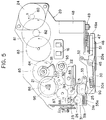
- Fig. 5 is a plan view showing the released condition of a platen holder while feeding the print tape in the reverse direction;
- Fig. 6 is a cross-sectional side view showing an open condition of the cover;
- Fig. 7 is a plan view showing operation of the cover and an interlocking mechanism of a press roller holder and a platen holder;
- Fig. 8 is a cross-sectional side view showing a closed condition of the cover;
- Fig. 9 is a cross-sectional view taken along the line IX-IX of Fig. 8;
- Fig. 10 is a cross-sectional view showing an essential portion of the platen holder;
- Fig. 11 is a cross-sectional view taken along the line XI-XI of Fig. 10;
- Fig. 12 is a cross-sectional view taken along the line XII-XII of Fig. 11;
- Fig. 13 is a cross-sectional view taken along the line XIII-XIII of Fig. 11;
- Fig. 14 is a cross-sectional view showing an essential portions of a press roller holder;
- Fig. 15 is a cross-sectional view taken along the line XV-XV of Fig. 14;
- Fig. 16 is a cross-sectional view taken along the line XVI-XVI of Fig. 15;
- Fig. 17 is a cross-sectional view taken along the line XVII-XVII of Fig. 15;
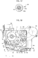
- Fig. 18 is an explanatory plan view showing a condition when the print tape is transported in a forward direction;
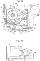
- Fig. 19 is an explanatory plan view showing a condition when the print tape is transported in a reverse direction;
- Fig. 20 is a view taken along the line XX-XX of Fig. 18;
- Fig. 21 is a front view showing a phase of a cam in a condition for operating the platen holder.
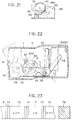
- Fig. 22 is a front view showing a cutting mechanism for cutting the print tape;
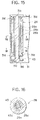
- Fig. 23 is an explanatory view showing one example of an ink ribbon;
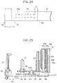
- Fig. 24 is an explanatory view showing dual line characters printed on the print tape and leading end and trailing end margins of the tape; and
- Fig. 25 is a cross-sectional side view showing a closed condition of the cover and particularly showing a rotation delaying mechanism;
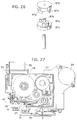
- Fig. 26 is a perspective view of gears in the delaying mechanism; and
- Fig. 27 is an explanatory plan view showing a state where a laminated type print tape housed in the cassette is installed in the tape printer.
- A tape printer according to one embodiment of the present invention will be described. Fig. 1 shows an external view of a
tape printer body 1 formed of a synthetic resin. A receivingportion 3 for receiving a cassette 2 (to be described later) is provided at one side in the upper surface of thebody 1. A freely openable andclosable cover 4 is provided for covering the receivingportion 3. Also provided at the upper surface of thebody 1 are akeyboard 5 for inputting characters and the like, aswitch panel 6 with switches for performing various operations, and aliquid crystal display 7 for displaying operation commands, inputted characters, and the like. The interior of theprinter body 1 is provided with a mechanical arrangement (to be described later), and a microcomputer (not shown) for control operations of the tape printer. - An internal arrangement of the
tape cassette 2 is shown in Fig. 2. A receptortype print tape 8 and anink ribbon 9 are accommodated in thecassette 2. Theprint tape 8 is wound on atape spool 10. Fourrollers 11 are provided for guiding travel of theprint tape 8. Thecassette 2 has atape release portion 12 from which theprint tape 8 is discharged from a cassette case body. Theprint tape 8 running along the fourrollers 11 is transported by tape transport means (described later) and passes along aprint portion 13 such as a thermal head (see Fig. 4). - The
ink ribbon 9 is wound around aribbon spool 15.Openings 18 are opened in the case body side of thecassette 2 at positions confronting a detection means 16, such as photo interrupters, in the receivingportion 3. Theink ribbon 9 is adapted to run through a detection path that passes between the detection means 16 and is guided past theprint portion 13 and therelease portion 12 in a path substantially parallel to path of theprint tape 8. A ribbon tape upspool 17 is provided for taking up theink ribbon 9 after it passes by theprint portion 13. Also, atape feed roller 19 is provided to thecassette 2 as one component of the tape transport means. - A
sensor part 301 is provided to thecassette 2. Thesensor part 301 includes six detected positions 301a through 301f, whose positions are predetermined so as to indicate the widthwise dimension ofprint tape 8, the variety (receptor type print tape on which positive images are printed or laminate type print tape on which mirror images are printed) of theprint tape 8, and the ink color of the mountedink ribbon 9. Thesensor part 301 is positioned so as to be detectable by detection switches 300a through 300f (Fig. 3 does not show switches 300a and 300b) that are provided to theprinter body 1. If no hole is opened at a sensor part, the corresponding detection switch is turned ON. If a hole is opened at a sensor part, the corresponding detection switch is turned OFF. For example, Fig. 3 shows detection switches 300c and 300f in an ON condition anddetection switches - The following Table 1 shows the relationship between ON or OFF conditions of the detection switches 300a through 300f and the kind of the
tape cassette 2, i.e., ink color, tape variety, and tape width of tapes.Table 1 Ribbon color Tape width Tape variety 300a 300b 300c 300d 300e 300f single ON ON 32mm ON ON receptor ON ON black/red ON OFF 24mm ON OFF laminate ON OFF black/blue OFF ON 18mm OFF ON cassette is not provided OFF OFF red/blue OFF OFF 12mm OFF OFF - Next, internal structure of the tape printer will be described with reference to Figs. 4 through 6. Incidentally, regarding the receptor-
type print tape 8, printing is performed on the surface of theprint tape 8 that confronts theink ribbon 9. The other surface of theprint tape 8 is precoated with an adhesive layer. A peelable tape is impermanently adhered to this adhesive layer. - The print tape transport means and the ink ribbon take up means will first be described. The
printer body 1 has aframe 20 to which provided are a tapereverse drive cam 21 capable of engaging with the inner peripheral surface of thetape spool 10, aribbon drive cam 22 for engaging with the inner peripheral surface of the ribbon take upspool 17, atape drive cam 23 for engaging with an inner peripheral surface of thetape feed roller 19, and theprint element 13, such as a thermal head. A bidirectionaltape drive motor 24 is provided, and agear train tape drive motor 24 to thetape drive cam 23. - A
press roller 26 is positioned in confrontation with the tape feed roller 19 (when the cassette is installed) to nip theprint tape 8. Further, agear 89 is provided for transmitting rotation of thegear 87 of the gear train to aplaten gear 90. Aswing arm 91 is provided coaxially with thegear 85 of the gear train. Aplanetary gear 92 is rotatably supported at a free end of theswing arm 91, and is meshedly engageable with thegear 85. Theplanetary gear 92 is also engageable with aribbon drive gear 93. Theribbon drive gear 93 is connected to theribbon drive cam 22 through a clutch spring (not shown). Ameshing gear 96 is provided at one axial end of thepress roller 26. Themeshing gear 96 is meshedly engageable with thegear 88 of the gear train, so that thetape feed roller 19 and thepress roller 26 are rotatable in synchronism. Further, anidler gear 94 is meshedly engageable with theplanetary gear 94. Theidler gear 94 is also engageable with areverse gear 95 provided coaxially with thegear 86 of the gear train. Thereverse gear 95 is connected to the tapereverse drive cam 21 through a clutch spring (not shown). - When the
cassette 2 is mounted in theprinter body 1 and printing operations are performed while theprint tape 8 is transported in the direction in which theprint tape 8 is drawn from the cassette 2 (i.e., the forward direction), the platen 25 (to be described later) presses against theprint element 13 so as to sandwich theprint tape 8 and theink ribbon 9 between itself and theprint element 13. Further, the press roller 26 (described later in detail) is caused to approach thetape feed roller 19 so as to sandwich the printedprint tape 8 therebetween. Thetape drive motor 24 is rotated in a normal direction (in the clockwise direction shown by the arrow A in Fig. 4) . The rotation force of thetape drive motor 24 is transmitted to theplaten gear 90 via thegear train 80 through 88 and thegear 89. - At the same time, since the
gear 85 rotates in the counterclockwise direction in Fig. 4 because of the normal rotation of thetape drive motor 24. Therefore, theswing arm 91, which is concentrically fixed to gear 85, is angularly moved in the counterclockwise direction. Therefore, theplanetary gear 92 rotates theribbon drive gear 93 in the counterclockwise direction, so that theink ribbon 9 is wound over the ribbon take upspool 17. In this case, the amount ofink ribbon 9 taken up over a unit of time increases with increase in the diameter of theink ribbon 9 taken up on the ribbon take upspool 17. However, high speed rotation of theribbon drive gear 93 cannot be directly transmitted to theribbon drive cam 23 because of the provision of the clutch spring (not shown) which provides slippage therebetween. Because of the slipping rotation of theribbon drive cam 22, loose winding of theink ribbon 9 is prevented. - On the other hand, when printing operations are temporarily interrupted, and the
print tape 8 is rewound (transported in the reverse direction), theink ribbon 9 is irrotational. That is, thetape drive cam 23 and the tapereverse drive cam 21 are rotated in the counterclockwise direction shown in Fig. 5 so as to transport theprint tape 8 in the reverse direction while it is sandwiched between thepress roller 26 and thetape feed roller 19. To this effect, thetape drive motor 24 is reversely driven (that is, in the counterclockwise direction indicated by the arrow B in Fig. 5). Therefore, thegear 85 is rotated in the clockwise direction in Fig. 5. Accordingly, theswing arm 91, which is concentrically fixed to thegear 85, is also rotated in the clockwise direction. Consequently, theplanetary gear 92 is disengaged from theribbon drive gear 93, to thus stop rotation of theribbon drive cam 22. Theplanetary gear 92 is brought into engagement with theidler gear 94, so that theplanetary gear 92 rotates thereverse gear 95 in the counterclockwise direction via theidler gear 94. Thus, the tapereverse drive cam 21 is reversely driven so that theprint tape 8 is wound onto thetape spool 10. In this case, theplaten 25 is positioned away from theprint element 13 as described later. - The swinging movement of the
swing arm 91 toward theidler gear 94 requires several time period. Therefore, reverse rotation start timing of thetape drive cam 23 is delayed in comparison with the reverse rotation start timing of thetape feed roller 19, thepress roller 26 and theplaten 25. Due to this delay, theprint tape 8 may be loosely wound in thecassette 2. To avoid this problem, in the illustrated embodiment, there is provided a rotation delaying mechanism for delaying reverse rotation start timing of thetape feed roller 19 and thepress roller 26. - As shown in Figs. 8, 25 and 26, the
gear 87 the gear train is constituted by first andsecond gears gear 87a and thegear 87b are intermittently connected. That is, thefirst gear 87a is provided with a pair ofarcuate ribs second gear 87b is provided with a pair ofarcuate ribs ribs gears first gear 87a is not promptly transmitted to thesecond gear 87b. Thus, thegears gear 87b is suitably delayed with respect to the rotation of thegear 87a. The rotation of thetape drive motor 24 is transmitted to thegear 87a, and thegears mesh gear 96 are driven by thegear 87b. Accordingly, the reverse rotation of thetape feed roller 19 and thepress roller 26 is delayed with respect to the start of reverse rotation of thetape drive motor 24. The amount of delay is set greater that the time of delay by the swing of the swingingarm 91. Therefore, theprint tape 8 will not be loosely rewound in thecassette 2. - Next, will be described an interlocking mechanism for moving the
platen 25 and thepress roller 26 when thecassette 2 is mounted and detached from theprinter body 1 while referring to Figs. 6 through 9.Pivot shafts frame 20. Apress roller holder 31, on which thepress roller 26 is mounted, is rotatably connected to thepivot shaft 33. Aplaten holder 30, on which theplaten 25 is mounted, is rotatably connected to pivotshaft 32.Holes platen holder 30 and thepress roller holder 31 respectively. - A
roller operation lever 35 and aplaten operation lever 34 are arranged to the rear surface (lower surface) of theframe 20. Theroller operation lever 35 and theplaten operation lever 34 are L-shaped in cross-section as best shown in Fig. 6.upstanding tip portions roller operation lever 35 and theplaten operation lever 34 are positioned intoholes Protrusion tip portions hole - The
platen operation lever 34 and theroller operation lever 35 are positioned so as to be movable parallel with the rear surface of theframe 20. Apivot shaft 36 extends horizontally from theframe 20, and an interlockinglever 37 having alower attachment portion 37a is rotatably supported on theshaft 36. Atorsion spring 40 is disposed at a pivot portion of the interlockinglever 37 so as to urge the interlockinglever 37 to pivotally rotate in the counterclockwise direction in Figs. 6 and 8. Theplaten operation lever 34 and theroller operation lever 35 are connected to thelower attachment portion 37a through tension springs 38 and 39, respectively. Theplaten operation lever 34 and theroller operation lever 35 have another ends each confronting thelower attachment portion 37a of the interlockinglever 37. - A
cover body 4 is provided to cover the tapecassette receiving portion 3. Thecover body 4 has anabutment portion 4a abuttable on the interlockinglever 37. Theabutment portion 41 protrudes from the inner surface of thecover body 4. Further, a hingedpin 41 is provided to theframe 20 for pivotally moving thecover body 4. - When
cover body 4 covers the receivingportion 3 as shown in Fig. 8, the back side (left side face in Fig. 8) of the interlockinglever 37 is pressed by theabutment portion 4a in a clockwise direction in Fig. 8. Therefore, theattachment portion 37a of the interlockinglever 37 is moved leftwardly in Fig. 8. As a result, both theplaten operation lever 34 and theroller operation lever 35 are moved toward left in Fig. 8 through the tension springs 38, 39. Consequently, theplaten holder 30 is pivotally moved about thepivot shaft 32 toward theprinting element 13 because of the engagement between thehole 30a and theupstanding tip end 34a, and thepress roller holder 31 is pivotally moved about thepivot shaft 33 toward thetape feed roller 19 because of the engagement between thehole 31a and theupstanding tip end 35a. Thus, theprint tape 8 and theink ribbon 9 can be nipped between theplaten 25 and theprint element 13, and theprint tape 8 can be nipped between thepress roller 26 and thetape feed roller 19. - On the other hand, when the
cover body 4 is opened by rotating on the hingedpin 41 as shown in Fig. 6, the interlockinglever 37 is released from theabutment portion 4a of thecover 4, and rotates as shown in Fig. 6 by the biasing force of thetorsion spring 40. This loosens the urging force produced by the tension springs 38 and 39. Also, when the interlockinglever 37 is rotated into the condition shown in Fig. 6, the front surface of the lowertip attachment portion 37a of the interlockinglever 37 pushed the other en faces 34b and 35b of both operation levers 34 and 35. Therefore, theupstanding tip portions holes platen holder 30 and thepress roller holder 31. Thus, theplaten holder 30 and thepress roller holder 31 are forcibly rotated to a direction away from theprinting element 13 and thetape feed roller 19. - As best shown in Fig. 10, the
platen 25 is integrally provided with aplaten gear 90 disposed at axially one end portion of theplaten 25, and driving force of thegear 89 is transmitted to theplaten gear 90. Further, as best shown in Fig. 14, thepress roller 26 is integrally provided with themesh gear 96 disposed at axially one end portion of thepress roller 26, and driving force of thegear 88 is transmitted to themesh gear 96. With this arrangement, the meshing engagement between thegears gears platen 25 and thepress roller 26 may lift from the surface of theprint element 13 and thetape feed roller 19, respectively. This makes it difficult to produce a uniform nipping pressure in the widthwise direction of theprint tape 8 and theink ribbon 9. In light of this, the present embodiment further provides self-centering mechanism in theplaten 25 and thepress roller 26 so as to provide uniform nipping pressure in the widthwise direction of thetape 8. - More specifically, the
platen 25 includes aspline shaft 42, aninner cylinder body 25a disposed over thespline shaft 42, and anouter cylinder body 25c disposed over theinner cylinder body 25a. Thespline shaft 42 has aspline portion 42a at its outer periphery thereof. One end of thespline shaft 42 is integrally provided with theplaten gear 90. Theplaten holder 30 is formed withattachment holes ribs spline shaft 42 is supported by the attachment holes 30c, 30c. Further, each axial end portion of theinner cylinder body 25a is guided by therib 30d so as to be movable in the direction for pressing against theprint element 13. Further, theribs inner cylinder body 25a from being moved in the direction perpendicular to the pressing direction, i.e., the direction in which theprint tape 8 moves. - An
inner cylinder body 25a is loosely engaged with thespline portion 42a. A plurality ofengagement protrusions 25b are provided at the inner diameter portion of theinner cylinder 25a. Theprotrusions 25b protrude radially inwardly at a position substantially at a central portion with respect to the length of theplaten 25. Theprotrusions 25b are engageable with the grooves of thespline portion 42a. Thus, theplaten 25 can rock on theengagement protrusions 25b with respect to an axis of the spline shaft 42 (see Figs. 10 through 13). When, via theplaten holder 30, theplaten 25 moves toward the print element 13 (to the left in Fig. 10) and presses against theprint element 13, theplaten gear 90 side of the axis of thespline shaft 42 may be moved in the direction away from theprint element 13 due to the above-described reactive force. However, since theplaten 25 is self-centered on theengagement protrusion 25b, theplaten 25 is pressed parallel to the surface of theprint element 13. Accordingly, the pressing force in the widthwise direction of the print tape and theink ribbon 9 between theprint element 13 and theplaten 25 can therefore be made uniform. - A similar structure can be applied to the
press roller 26 in thepress roller holder 31. Thepress roller 26 includes aspline shaft 43, aninner cylinder body 26a disposed over thespline shaft 43, and anouter cylinder body 26c disposed over theinner cylinder body 26a. Thespline shaft 43 has aspline portion 43a at its outer periphery thereof. One end of thespline shaft 43 is integrally provided with themesh gear 96. Thepress roller holder 31 is formed withattachment holes ribs spline shaft 43 is supported by the attachment holes 31c, 31c. Further, each axial end portion of theinner cylinder body 26a is guided by therib 31d so as to be movable in the direction for pressing against thetape feed roller 19. Further, theribs inner cylinder body 26a from being moved in the direction perpendicular to the pressing direction, i.e., the direction in which theprint tape 8 moves. - An
inner cylinder body 25a is loosely engaged with thespline portion 43a. A plurality ofengagement protrusions 26b are provided at the inner diameter portion of theinner cylinder 26a. Theprotrusions 26b protrude radially inwardly at a position substantially at a central portion with respect to the length of thepress roller 26. Theprotrusions 26b are engageable with the grooves of thespline portion 43a. Thus, thepress roller 26 can rock on theengagement protrusions 26b with respect to an axis of the spline shaft 43 (see Figs. 14 through 17). When, via thepress roller holder 31, thepress roller 26 moves toward the tape feed roller 19 (to the left in Fig. 14) and presses against thetape feed roller 19, themesh gear 96 side of the axis of thespline shaft 43 may be moved in the direction away from thetape feed roller 19 due to the above-described reactive force. However, since thepress roller 26 is self-centered on theengagement protrusion 26b, thepress roller 26 is pressed parallel to the surface of thetape feed roller 19. Accordingly, the pressing force in the widthwise direction of the print tape between thetape feed roller 19 and thepress roller 26 can therefore be made uniform. - Next, a platen moving mechanism will be described with reference to Figs. 18 through 21. The platen moving mechanism is adapted to move the
platen 25 toward and away from theprinting element 13 when theprint tape 8 of thetape cassette 2 installed in thecassette receiving portion 3 of the tape printer is moved in forward and rewinding or reverse direction, respectively. - As described above, when the
tape cassette 2 is installed in thecassette receiving portion 3 and thecover 4 is closed, the interlockinglever 37 becomes vertical (Fig. 8) and the urging force of thetension spring 38 rotates theplaten holder 30 via theplaten operation lever 34. In this case, theplaten 25 presses against the print element 13 (see Fig. 18). The platen moving mechanism allows theplaten 25 to move away from theprint element 13 even if thecover 4 is closed in order to prevent theink ribbon 9 from being reversely fed by the platen. - A
platen moving lever 46 is provided having a base end rotatably supported to ashaft 45 connected to theplaten holder 30, and having a free end provided with anabutment portion 46a. Aplaten moving motor 48 is fixed to theframe 20, and agear train 49 is provided to transmit the rotation of theplaten moving motor 48 to acam 47. Theabutment portion 46a of theplaten moving lever 46 is abuttable on a peripheral surface of thecam 47. - The
platen moving lever 46 is positioned between thecam 47 and an upwardlybent portion 20a of theframe 20 so that range of movement of theplaten moving lever 46 is restricted to only reciprocal movement in a direction parallel to the upwardlybent portion 20a. Thecam 47 rotates unidirectionally (counterclockwise direction in Fig. 20) via thegear train 49 from theplaten moving motor 48. Theplaten moving lever 46 is pulled rightward in Fig. 19 at a predetermined rotation phase position of thecam 47 so that theplaten holder 30 moves away from theprint element 13 against the biasing force of thetension spring 38. As shown in Figs. 20 and 21, thecam 47 is integrally provided with asensor plate 51, and arelief switch 50 is provided to detect thesensor plate 51. - Thus, the moving phase of the
platen holder 30 is detected by detecting the rotation phase of thecam 47 using the ON/OFF status of therelief switch 50. That is, when theplaten holder 30 is in a pressing condition against theprint element 13 as shown in Figs. 18 and 20, the tip of thesensor plate 51 does not abut therelief switch 50 and so therelief switch 50 is rendered OFF. For continuing printing operation, this state is maintained by deenergizing theplaten moving motor 48 when thecam 47 is rotated to the position shown in Fig. 20. - The unidirectionally rotating
platen moving motor 48 rotates in the counterclockwise direction in Figs. 20 and 21. With counterclockwise rotation of thecam 47, the tip of thecam 47 presses theabutment portion 46a of theplaten moving lever 46 in the rightward direction in Fig. 19. Theplaten holder 30 is moved away from theprint element 13. At this time, therelief switch 50 is rendered ON by thesensor plate 51, so that theplaten moving motor 48 is deenergized. - Accordingly, when the tape printer is not being used, while installing the
tape cassette 2 in thecassette receiving portion 3, theplaten 25 can be maintained separated from theprint element 13. This prevents theplaten 25, which is made from a soft material such as rubber, from being permanently deformed by being pressed against the surface of theprint element 13. On the other hand, when theplaten holder 30 is moving from the separated condition to the pressing condition, therelief switch 50 remains ON until theplaten holder 30 is completely in a pressing condition, whereupon the relief switch is rendered OFF. - If the
cam 47 is in the position shown in Fig. 21, while printing to thetape cassette 2 in thecassette receiving portion 3 is intended, theplaten moving motor 48 is first energized in response to the depression of the print switch, and is then deenergized upon completion of 180 degree rotation to maintain the cam position shown in Fig. 20. Therefore, theplaten 25 is positioned at its nipping position relative to theprint element 13. - In the present embodiment, the
platen holder 30 can be angularly moved to a position away from theprint element 13 by the rotation of thecam 47. Also, theplaten holder 30 and thepress roller holder 31 can be angularly moved in the separation direction via thepressing operation lever 35, theplaten operation lever 34, and the tension springs 38 and 39 in accordance with the opening and closing movement of thecover 4. Therefore, whether the operation of theplaten moving motor 48 brings theplaten holder 30 in the pressing condition or the separated condition, theplaten holder 30 and thepressing holder 31 are forced to move into the separation condition when thecover 4 is opened. Therefore an operator can changecassettes 2 regardless of the rotational phase of thecam 47. - Next, a
cutting mechanism 52 for cutting theprint tape 8 will next be provided with reference to Figs. 4 and 22. Thecutting mechanism 52 includes a fixedblade 53, amovable blade 54, and acutter motor 55 for driving themovable blade 54. The fixedblade 53 is fixed to the upwardly protruding portion 20b of theframe 20. Themovable blade 54 is rotatably mounted on asupport shaft 56, which is adjacent to the fixedblade 53. Themovable blade 54 has aconnection arm 62 extending from the base end of themovable blade 54. Theconnection arm 62 is formed with a bifurcated portion. Aspring washer 57 is provided for urging themovable blade 54 towards the fixedblade 53. - A disk-shaped
operation disk 60 is rotatably supported on theframe 20. Anengagement pin 61 protrudes from one surface of theoperation disk 60. Thedisk 60 is formed with anindentation 60a in an outer peripheral surface thereof. Further, acutter motor 55 is provided for unidirectionally rotating the disk-shapedoperation disk 60 via agear train 58. Theengagement pin 61 is slidably freely engageable between the two prongs of theconnection arm 62 for pivotally moving themovable blade 54. Arelief switch 63 is provided to be engageable with theindentation 60a. - One rotation of the
operation disk 60 moves themovable blade 54 from an open position as shown by the solid line in Fig. 22 to a temporary closed position as shown by the two dot chain line, and then again to the open position by the sliding engagement between thepin 61 and theconnection arm 62. Therelief switch 63 turns OFF when it abuts theindentation 60a. Therefore, thecutter motor 55 is deenergized for stopping themovable blade 54 at its open position. - Next, operation of the tape printer will be described. Figs. 18 and 19 show printing operations wherein the
cassette 2 houses a receptor-type print tape 8. In the present embodiment, a distance L of 25 mm separates theprint element 13 from the position where theprint tape 8 is cut by thecutting mechanism 52. Further, as shown in Fig. 23, theink ribbon 9 housed in thecassette 2 is colored in the lengthwise direction alternately with ablack ink portion 70 and ared ink portion 71 withmark portions - Colors are distinguished by the light transmission type detection means 16 (Fig. 4). More specifically, the
mark portion 73 is provided with a single black bar code before theblack ink portion 70, and themark portion 74 is provided with two black bar codes before thered ink portion 71. Each bar code is detectable by the detection means 16. The following description will be provided for printing two levels of character trains in the widthwise direction of theprint tape 8 using the two-color ink ribbon 9 as described above. - When the
cassette 2 is set in the receivingportion 3 of theprinter body 1, the ink color, the width of theprint tape 8, and the type ofprint tape 8 are distinguished by the combination of ON and OFF signals from the detection switches 300a through 300f, which are mounted to thebody 1 in accordance with the Table 1. Next, color and the like are commanded (inputted) using the operation switches 6 on theprinter body 1 and characters are inputted using thekeyboard 5. When the print switch is depressed, thetape drive motor 24 rotates in the normal direction. At first, it is impossible to distinguish which color ink portion of theink ribbon 9 is located (either red or black) at theprint element 13. Therefore, theink ribbon 9 and theprint tape 8 are feed to a predetermined position. As shown in Fig. 18, in this case, theplaten 25 of theplaten holder 30 and thepress roller 26 of thepress roller holder 31 press against theprint element 13 and thetape feed roller 19, respectively. The amount at which theink ribbon 9 and theprint tape 8 are feed is controlled by the amount at which thetape feed roller 19 and thepress roller 26 are rotated. At first, the feed amount at which theink ribbon 9 is fed is the sum of the distance L (25 mm in the present embodiment) added to the amount that must be fed until themark portion 73 for theblack ink portion 70 or themark portion 74 for thered ink portion 71 is detected by the detection means 16. - For example, if the
black ink portion 70 is first detected, printing is first performed with black ink. If the length of the image, such as a character train, is 15 cm, theprint tape 8 and theink ribbon 9 are integrally rapidly fed 5 cm even if printing is completed. The pitch by the sum of the ink portion and the mark portion is constant (20 cm) irrespective of the colors, and the amount in which theink ribbon 9 is fed is controlled by the amount in which theprint tape 8 is fed (20 cm). Therefore, by distinguishing the color by themark portion - Next, the
platen operation motor 48 is driven so that theplaten holder 30 is angularly moved to move theplaten 25 away from the print element 13 (see Fig. 19) by the engagement between thecam 47 and theabutment portion 46a of theplaten connection lever 46. As shown in Fig. 5, when thetape drive motor 24 is reversely rotated, thegear 84 of the gear train will rotate in the clockwise direction. Thus, theplanet gear 92, which is supported on the swingingarm 91, disengages from thegear 93 of theribbon drive cam 22. Therefore, take up of theink ribbon 9 is stopped. On the other hand, theplanetary gear 92 engages theidler gear 94 to causes thegear 95 to rotate in the counterclockwise direction. Further, thetape feed roller 19 is also rotated in the couterclockwise direction by the rotation of thegears 86 through 88. Thepress roller 26 is forced to rotate by the engagement of thegear 88 and themesh gear 96. Theprint tape 8 nipped between therollers - In the reverse feeding of the printed
tape 8, the reverse rotation start timing of theplaten 25, thetape feed roller 19 and thepress roller 19 is delayed by thegears print tape 8 will not be loosely rewound in thecassette 2. - Next, the
platen operation motor 48 is driven so that theplaten holder 30 is pivotally moved, thereby causing theplaten 25 to press against the surface of theprint element 13. Afterward, thetape drive motor 24 is rotated in the normal direction so that character train can be printed in red on the lower level. Incidentally, other printing layout is performed. For example, a singlecolor ink ribbon 9 is used instead of theribbon 9 shown in Fig. 23. After printing a character train on theprint tape 8, theprint tape 8 is rewound, and another character train is printed on the second level of theprint tape 8 in the widthwise direction of theprint tape 8, thus printing two line character trains with the identical color. Alternatively, an ornamental frame can be printed around the character train, or the character train can be printed over again to form bold print. Regardless, as described above, after the first character train is printed, theprint tape 8 only is rewound a suitable distance while theink ribbon 9 remains stationary. Printing can then again be executed. - Next, will be described with reference to Fig. 24, operation for reducing the margin by shortening the distance from the end portion (cut edge) in the lengthwise direction of the
print tape 8 to the start of the character train. In the present embodiment, L1 is the distance from theprint element 13 to thecutting mechanism 52. Conventionally theprint tape 8 is transported only toward where theprint tape 8 exits from the tape printer. Therefore, the position of theprint tape 8 when printing starts comes after the position of the margin at distance L1, thereby producing a long margin. - In the present embodiment, before printing starts, the
print tape 8 is rewound only the distance L2 (which is less that the distance L1) and rewinding stops. Next, the printing operations are executed while theprint tape 8 is transported in the forward direction. - Further, a trailing end margin length can also be controlled. For example, after an
image 75, such as a character train as described previously, is printed, theprint tape 8 and theink ribbon 9 are transported forward only the margin distance L3 in addition to the distance L1 from the terminal edge of the printed image region. Then theprint tape 8 is cut at thecut portion 76b. More specifically, the character "G" or "g" is positioned at theprinting element 13 when completing the printing. By forwardly moving the print tape by the length L1, the rear edge of the character "G" or "g" reaches thecutting mechanism 52. Then by further moving the print tape by the length L3, thecutting edge 76b reaches thecutting mechanism 52. When printing is next performed, printing is started after theprint tape 8 is rewound a suitable distance L2. In this way, a long margin distance is not produced and printing can be performed without wastingprint tape 8. - Fig. 27 shows a second embodiment in which performed is printing to a laminate type print tape housed in the
cassette 2. In case of thetape cassette 2 accommodating therein the laminate type print tape, atransparent tape 77, anink ribbon 9, and a dual-sidedadhesive tape 78 are housed in thecassette 2. Thetransparent tape 77 is adapted to pass through the detection means 16 instead of theink ribbon 9 in contrast to the receptor type tape cassette. - The
cassette 2 is mounted in theprinter body 1 in the same manner as in the foregoing embodiment. Thetransparent tape 77 and theink ribbon 9 are transported forward in the direction of theprint element 13 while a mirror image of the image, such as characters, is printed on thetransparent tape 77. Afterward, thetransparent tape 77 and the dual-sidedadhesive tape 78 are fed stacked one on the other between thetape feed roller 19 and thepress roller 26 so that the printing surface of thetransparent tape 77 adheres to one of the adhesive surfaces of the dual-sidedadhesive tape 78. The other adhesive surface of the dual-sidedadhesive tape 78 has a peelable tape (not shown), coated with a parting agent, such as silicon, temporarily attached thereto. The print tape is prohibited from being transported in the reverse direction for two color printing, or two line printing, since theadhesive tape 78 has already been adhered onto the printed surface of thetransparent tape 77 in the first printing. - In the first embodiment, a
non-transparent tape 79, such as aluminum tape, can be connected between the terminal end of theink ribbon 9 and thespool 15 for detecting the terminal end of theink ribbon 9. Upon detecting thenon-transparent tape 79 by the detection means 16, subsequent printing operation of the tape can be stopped. Further, in the second embodiment, thenon-transparent tape 79 can also be connected to the terminal end of thetransparent tape 77 in case thetransparent tape 77 used is laminated type. Thenon-transparent tape 79 can be detected by the detection means 16, since thetransparent tape 77 passes the detection means 16. - Further, in the above described embodiments, the
ink ribbon 9 is used for printing. However, theink ribbon 9 can be dispensed with by employing a heat-sensitive-coloring print tape. In this case, the heat-sensitive-coloring tape may be non-transparent. For detecting the terminal end of the print tape, its terminal end is connected with a transparent zone, so that the detection means 16 can detect the terminal end of the non-transparent heat-sensitive-coloring print tape. - While the invention has been described in detail and with reference to specific embodiments thereof, it would be apparent to those skilled in the art that various changes and modifications may be made therein without departing from the spirit and scope of the invention.
Claims (18)
- A tape printer having a tape cassette receiving portion for installing a cassette therein, the tape cassette housing therein a print tape, a tape spool which winds thereon the printing tape, an ink ribbon, an ink ribbon take up spool for taking up the ink ribbon therearound and a tape feed roller, the tape printer comprising:
a frame;
printing means provided on the frame for printing an image on the print tape through the ink ribbon, the printing means comprising a platen and a print element which are provided external to the tape cassette when it is installed in the tape cassette receiving portion;
ribbon take up means provided on the frame for taking up the ink ribbon that passes between the platen and the print element in a forward direction;
tape transport means provided on the frame for transporting the print tape in the forward direction and a reverse direction;
means for preventing the ribbon take up spool from its reversal rotation to prevent the ink ribbon from being rewound over the ribbon take up spool when the tape transport means moves for reversely transporting the print tape; and
means for moving the platen away from the printing element when the tape transport means moves for reversely transporting the print tape. - The tape printer as claimed in claim 1, wherein the tape transportation means comprises:
a reversible drive motor;
a gear train comprising a plurality of gears for transmitting rotation of the reversible drive motor;
a first tape drive cam connected to the gear train and engageable with the tape feed roller; and
a second tape drive cam connected to the gear train and engageable with the tape spool. - The tape printer as claimed in claim 1 or 2, wherein the ribbon take up means comprises;
the reversible drive motor;
the gear train comprising a plurality of gears for transmitting rotation of the reversible drive motor;
a ribbon drive cam engageable with the ribbon take up spool;
a ribbon drive gear connected to the ribbon drive cam; and
a planetary gear engaged with the gear train and selectively engageable with the ribbon drive gear. - The tape printer as claimed in one of claims 1 to 3, wherein the preventing means comprises:
a swing arm having one end concentrically supported on the gear train and having another end rotatably supporting the planetary gear; and
clutch means for transmitting rotation of the gear train to the swing arm and allowing slippage of the swing arm relative to the gear train, the swing arm being swingable in one direction in response to normal rotation of the reversible drive motor to engage the planetary gear with the ribbon drive gear and swingable in opposite direction in response to reversal rotation of the reversible drive motor to disengage the planetary gear from the ribbon drive gear. - The tape printer as claimed in one of claims 1 to 4, wherein the platen moving means comprises;
a platen holder supporting the platen and rotatably supported on the frame for moving the platen toward and away from the print element; and
means for moving the platen holder away from the printing element, the means for moving the platen holder being connected to the platen holder. - The tape printer as claimed in claim 5, wherein the means for moving the platen holder comprises;
a platen moving lever having one end pivotally connected to the platen holder and having another end;
a platen moving motor supported on the frame; and
a cam member rotatable by the rotation of the platen moving motor, the cam member having a cam surface to which the other end of the platen moving lever is abuttable. - The tape printer as claimed in one of claims 1 to 6, further comprising:
a cover pivotally supported to the frame for closing the tape cassette receiving portion;
a press roller provided in pressure contact with the tape feed roller; and
interlocking means for moving the platen and the press roller toward and away from the print element and the tape feed roller respectively in accordance with a closing movement and opening movement of the cover, respectively. - A tape printer having a tape cassette receiving portion for installing a cassette therein, the tape cassette housing therein a print tape, a tape spool which winds thereon the printing tape and a tape feed roller, the tape printer comprising:
a frame;
printing means provided on the frame for printing an image on the print tape, the printing means comprising a platen and a print element which are provided external to the tape cassette when it is installed in the tape cassette receiving portion;
tape transport means provided on the frame for transporting the print tape in the forward direction and a reverse direction;
a cover pivotally supported to the frame for closing the tape cassette receiving portion;
a press roller provided in pressure contact with the tape feed roller; and
interlocking means for moving the platen and the press roller toward and away from the print element and the tape feed roller respectively in accordance with a closing movement and opening movement of the cover, respectively. - The tape printer as claimed in claim 8, further comprising;
a platen holder pivotally supported on the frame, the platen holder supporting the platen, the pivotal movement of the platen holder moving the platen toward and away from the print element; and
a press roller holder pivotally supported on the frame, the press roller holder supporting the press roller, pivotal movement of the press roller holder moving the press roller toward and away from the tape feed roller. - The tape printer as claimed in claim 8 or 9, wherein the interlocking means comprises:
an interlocking lever having an intermediate portion pivotally supported to the frame, one end portion abuttable on the cover, and another end portion;
first and second tension springs each one end being connected to the other end portion of the interlocking lever;
a platen operation lever having one end abuttable with the other end portion of the interlocking lever and connected to the first tension spring, the platen operation lever having another end engageable with the platen holder;
a roller operation lever having one end abuttable with the other end portion of the interlocking lever and connected to the second tension spring, the roller operation lever having another end engageable with the press roller holder. - The tape printer as claimed in one of claims 1 to 10, wherein
the ink ribbon has ink sections of different colors, the ink sections being arrayed in a lengthwise direction of the ink ribbon with a space between neighboring ink sections, and mark is provided in each of the space for indicating the color of a subsequent ink section, and
the tape printer further comprising means for detecting the mark. - A tape printer having a tape cassette receiving portion for installing a cassette therein, the tape cassette housing therein a print tape, a tape spool which winds thereon the printing tape and a tape feed roller, the tape printer comprising:
a frame;
a print element supported on the frame for printing an image on the print tape, the print element having a printing surface;
a platen movable toward and away from the print element, the platen having one axial end provided with a gear;
means for directing the platen in parallel with the printing surface when the platen nips the print tape with respect to the printing surface of the print element. - The tape printer as claimed in claim 12, wherein the directing means comprises:
projections projecting radially inwardly from the inner cylinder body at an axially intermediate portion thereof, the projections being engageable with the grooves of the spline shaft; the inner and outer cylinder bodies being tiltable with respect to the spline shaft about the projections. - The tape printer as claimed in one of claims 1 to 13, further comprising:
a press roller movable toward and away from the tape feed roller; and
means for directing the press roller in parallel with an axis of the tape feed roller. - The tape printer as claimed in one of claims 12 to 14, further comprising a platen holder and/or a press roller holder pivotally supported to the frame; and wherein the press roller comprises:
a spline shaft formed with grooves having one end provided with the gear and both end rotatably supported to the press roller holder;
an inner cylinder body loosely disposed over the spline shaft;
an outer cylinder body disposed over the inner cylinder body, the outer cylinder body and the tape feed roller nipping the print tape therebetween. - The tape printer as claimed in one of claims 12 to 15, wherein the directing means comprises:
projections projecting radially inwardly from the inner cylinder body of the press roller at an axially intermediate portion thereof, the projections being engageable with the grooves of the spline shaft; the inner and outer cylinder bodies of the press roller being tiltable with respect to the spline shaft about the projections. - A tape printer having a tape cassette receiving portion for installing a cassette therein, the tape cassette housing therein a print tape, a tape spool which winds thereon the printing tape, a tape feed roller, an ink ribbon and an ink ribbon take up spool, the tape printer comprising:
a frame;
a print element supported on the frame;
a platen supported on the frame and movable toward and away from the print element;
a press roller supported on the frame and movable toward and away from the tape feed roller when the tape cassette is installed in the cassette receiving portion;
a reversible drive motor supported to the frame;
a gear train engaged with the reversible drive motor for transmitting normal rotation of the reversible drive motor to the tape spool, the tape feed roller, the press roller, the platen and the ink ribbon take up spool, and for transmitting reversal rotation of the reversible drive motor to the tape feed roller and the press roller;
a reverse gear connectable to the tape spool;
means for disconnecting the gear train to the ink ribbon take up spool when the reversible drive motor rotates in a reverse direction, the disconnecting means being movable between the reverse gear and the ink ribbon take up spool with a time period; and
means for retarding a reversal rotation start timing of the press roller and the tape feed roller, a retarding period being greater than the time period. - The tape printer as claimed in one of claims 1 to 17, wherein the retarding means comprises:
a first gear engaged with the drive motor;
a second gear engageable with the tape feed roller and the press roller, the first gear being provided with at least one first arcuate rib and the second gear being provided with at least one second arcuate rib spaced away from the first arcuate rib in a circumferential direction thereof, the first arcuate rib being engageable with the second arcuate rib for integral rotation of the second gear with the first gear.
Priority Applications (1)
| Application Number | Priority Date | Filing Date | Title |
|---|---|---|---|
| EP01105310A EP1116594B1 (en) | 1993-09-06 | 1994-09-02 | Tape printer |
Applications Claiming Priority (3)
| Application Number | Priority Date | Filing Date | Title |
|---|---|---|---|
| JP5221426A JPH0768814A (en) | 1993-09-06 | 1993-09-06 | Tape printing device |
| JP22142693 | 1993-09-06 | ||
| JP221426/93 | 1993-09-06 |
Related Child Applications (1)
| Application Number | Title | Priority Date | Filing Date |
|---|---|---|---|
| EP01105310A Division EP1116594B1 (en) | 1993-09-06 | 1994-09-02 | Tape printer |
Publications (3)
| Publication Number | Publication Date |
|---|---|
| EP0641663A2 true EP0641663A2 (en) | 1995-03-08 |
| EP0641663A3 EP0641663A3 (en) | 1998-01-07 |
| EP0641663B1 EP0641663B1 (en) | 2001-12-12 |
Family
ID=16766561
Family Applications (2)
| Application Number | Title | Priority Date | Filing Date |
|---|---|---|---|
| EP01105310A Expired - Lifetime EP1116594B1 (en) | 1993-09-06 | 1994-09-02 | Tape printer |
| EP94113768A Expired - Lifetime EP0641663B1 (en) | 1993-09-06 | 1994-09-02 | Tape printer |
Family Applications Before (1)
| Application Number | Title | Priority Date | Filing Date |
|---|---|---|---|
| EP01105310A Expired - Lifetime EP1116594B1 (en) | 1993-09-06 | 1994-09-02 | Tape printer |
Country Status (4)
| Country | Link |
|---|---|
| US (2) | US5536092A (en) |
| EP (2) | EP1116594B1 (en) |
| JP (1) | JPH0768814A (en) |
| DE (2) | DE69429395T2 (en) |
Cited By (20)
| Publication number | Priority date | Publication date | Assignee | Title |
|---|---|---|---|---|
| EP0734871A2 (en) * | 1995-03-29 | 1996-10-02 | Brother Kogyo Kabushiki Kaisha | Tape-shaped label printing device |
| EP0764545A2 (en) * | 1995-09-21 | 1997-03-26 | Casio Computer Co., Ltd. | Colour printer |
| EP0767066A2 (en) * | 1995-10-04 | 1997-04-09 | Casio Computer Co., Ltd. | Printer and printing method |
| EP0787591A1 (en) * | 1996-01-31 | 1997-08-06 | Brother Kogyo Kabushiki Kaisha | Tape-shaped label printing device |
| WO1998016391A1 (en) * | 1996-10-14 | 1998-04-23 | Esselte N.V. | Tape printing apparatus |
| WO1999044835A1 (en) * | 1998-03-02 | 1999-09-10 | Brady Worldwide, Inc. | Method and apparatus for maintaining ribbon tension |
| US6132120A (en) * | 1995-03-29 | 2000-10-17 | Brother Kogyo Kabushiki Kaisha | Tape-shaped label printing device |
| EP1288006A2 (en) * | 1994-05-25 | 2003-03-05 | Brother Kogyo Kabushiki Kaisha | Tape cassette |
| EP0769385B2 (en) † | 1995-10-17 | 2003-07-30 | Brother Kogyo Kabushiki Kaisha | Tape-shaped label printing device usable with ribbon cassettes having newly added colors |
| GB2388573A (en) * | 2002-05-13 | 2003-11-19 | Esselte Nv | A label printer |
| GB2394208A (en) * | 2002-09-19 | 2004-04-21 | Esselte Nv | Tape printer having spitter mechanism that ejects tape from printer |
| EP0769386B2 (en) † | 1995-10-19 | 2004-11-10 | Brother Kogyo Kabushiki Kaisha | Tape-shaped label printing device |
| US7059791B2 (en) | 2002-09-19 | 2006-06-13 | Dymo | Tape printer |
| EP1698476A1 (en) * | 2005-03-01 | 2006-09-06 | Brother Kogyo Kabushiki Kaisha | Tape printer |
| WO2007057779A2 (en) | 2005-10-25 | 2007-05-24 | Dymo | Tape printing apparatus |
| EP1650035A3 (en) * | 2004-10-22 | 2008-03-19 | Dymo Corporation | Hybrid printer |
| US7616338B2 (en) | 2002-05-13 | 2009-11-10 | Dymo | Label printer |
| CN102259506A (en) * | 2010-05-31 | 2011-11-30 | 兄弟工业株式会社 | Printer |
| CN108973340A (en) * | 2017-05-31 | 2018-12-11 | 兄弟工业株式会社 | Printing device |
| US20220134772A1 (en) * | 2020-10-30 | 2022-05-05 | Brother Kogyo Kabushiki Kaisha | Printing device including power transmission mechanism configured to switch rotation speed of platen roller in association with attachment of cassette |
Families Citing this family (58)
| Publication number | Priority date | Publication date | Assignee | Title |
|---|---|---|---|---|
| US5595447A (en) * | 1992-10-13 | 1997-01-21 | Seiko Epson Corporation | Tape cartridge and printing device having print medium cartridge |
| US5411339A (en) * | 1993-12-09 | 1995-05-02 | Kroy, Inc. | Portable printer and cartridge therefor |
| US6190069B1 (en) | 1994-05-25 | 2001-02-20 | Brother Kogyo Kabushiki Kaisha | Tape-shaped label printing device |
| US6196740B1 (en) * | 1994-05-25 | 2001-03-06 | Brother Kogyo Kabushiki Kaisha | Tape-shaped label printing device |
| US6042280A (en) * | 1995-05-25 | 2000-03-28 | Brother Kogyo Kabushiki Kaisha | Tape label printing device |
| JP3111445B2 (en) * | 1995-03-29 | 2000-11-20 | ブラザー工業株式会社 | Tape-shaped label making device |
| JPH08169155A (en) * | 1994-10-21 | 1996-07-02 | Seiko Epson Corp | Ink-jet printer as well as recording medium and recording medium supply source for the printer |
| JP3438447B2 (en) | 1994-12-28 | 2003-08-18 | セイコーエプソン株式会社 | Printing apparatus and printing method for tape-shaped recording medium, and tape-shaped recording medium |
| JP3213210B2 (en) * | 1995-06-14 | 2001-10-02 | アルプス電気株式会社 | Thermal printer |
| KR100407080B1 (en) * | 1995-08-10 | 2004-03-26 | 세이코 엡슨 가부시키가이샤 | Cartridge for ink jet printer and ink jet printer |
| KR0151099B1 (en) * | 1995-12-29 | 1998-12-01 | 김광호 | Thermal transfer printer |
| JP3564848B2 (en) * | 1996-02-16 | 2004-09-15 | ブラザー工業株式会社 | Tape cassette |
| JPH09254450A (en) * | 1996-03-26 | 1997-09-30 | Brother Ind Ltd | Print tape prep aring device |
| JP3691618B2 (en) * | 1996-04-15 | 2005-09-07 | セイコーエプソン株式会社 | Tape printer |
| GB9701831D0 (en) * | 1997-01-29 | 1997-03-19 | Neopost Ltd | Thermal transfer printing apparatus |
| US5797687A (en) * | 1997-03-11 | 1998-08-25 | Hewlett-Packard Company | Paper stacker activation for printer input/output |
| JP3711427B2 (en) * | 1997-09-18 | 2005-11-02 | カシオ計算機株式会社 | Tape printer |
| DE60020164T2 (en) * | 1999-08-06 | 2006-01-26 | Brother Industries Ltd. | TAPE CASSETTE |
| JP2001047679A (en) * | 1999-08-12 | 2001-02-20 | Seiko Epson Corp | Tape printer |
| EP1084852B1 (en) | 1999-09-14 | 2003-11-19 | Brother Kogyo Kabushiki Kaisha | Cassette and detecting device for installation thereof |
| JP4126214B2 (en) * | 2002-09-24 | 2008-07-30 | ブラザー工業株式会社 | Label tape printer |
| CN101683790B (en) * | 2002-12-24 | 2013-01-02 | 迪默公司 | Printing device and cassette |
| JP2005053182A (en) | 2003-08-07 | 2005-03-03 | Brother Ind Ltd | Tape printer and tape printing system |
| JPWO2006033430A1 (en) * | 2004-09-24 | 2008-05-15 | ブラザー工業株式会社 | Tape cassette and tape printer |
| MX2007011310A (en) * | 2005-03-16 | 2007-10-08 | Panduit Corp | Hand-held thermal transfer printer for labeling. |
| JP4561442B2 (en) * | 2005-03-30 | 2010-10-13 | ブラザー工業株式会社 | Tape cassette |
| US8100595B2 (en) * | 2007-12-07 | 2012-01-24 | Dymo | Label printing apparatus |
| GB2459531B (en) * | 2008-04-29 | 2010-10-13 | Dymo Nv | Label printer |
| JP5093046B2 (en) * | 2008-10-22 | 2012-12-05 | ブラザー工業株式会社 | Tape printer |
| JP4978733B2 (en) | 2008-10-22 | 2012-07-18 | ブラザー工業株式会社 | Tape cassette |
| KR20150038644A (en) | 2008-12-25 | 2015-04-08 | 브라더 고오교오 가부시키가이샤 | Tape cassette |
| EP2202082B1 (en) | 2008-12-25 | 2012-02-15 | Brother Kogyo Kabushiki Kaisha | Tape printer |
| JP4947085B2 (en) * | 2009-03-31 | 2012-06-06 | ブラザー工業株式会社 | Tape cassette |
| CN201989425U (en) * | 2009-03-31 | 2011-09-28 | 兄弟工业株式会社 | Band box and band printer |
| WO2010113441A1 (en) | 2009-03-31 | 2010-10-07 | Brother Kogyo Kabushiki Kaisha | Tape cassette and tape printer |
| PT2414165E (en) * | 2009-03-31 | 2014-04-17 | Brother Ind Ltd | Tape cassette and tape printer |
| JP5136503B2 (en) | 2009-03-31 | 2013-02-06 | ブラザー工業株式会社 | Tape cassette |
| EP2415610B1 (en) | 2009-03-31 | 2019-07-03 | Brother Kogyo Kabushiki Kaisha | Tape cassette |
| EP2415612B1 (en) * | 2009-03-31 | 2019-09-25 | Brother Kogyo Kabushiki Kaisha | Tape cassette |
| JP5267292B2 (en) * | 2009-04-10 | 2013-08-21 | ブラザー工業株式会社 | Printing device |
| ATE544604T1 (en) * | 2009-06-10 | 2012-02-15 | Brother Ind Ltd | PRINTER |
| US20100329767A1 (en) * | 2009-06-30 | 2010-12-30 | Brother Kogyo Kabushiki Kaisha | Tape cassette |
| JP5347767B2 (en) * | 2009-06-30 | 2013-11-20 | ブラザー工業株式会社 | Tape printer |
| US8641304B2 (en) | 2009-06-30 | 2014-02-04 | Brother Kogyo Kabushiki Kaisha | Tape cassette |
| JP5146415B2 (en) * | 2009-06-30 | 2013-02-20 | ブラザー工業株式会社 | Tape printer |
| JP5326950B2 (en) * | 2009-09-09 | 2013-10-30 | ブラザー工業株式会社 | Tape cassette |
| JP5212550B2 (en) | 2009-12-16 | 2013-06-19 | ブラザー工業株式会社 | Tape cassette |
| WO2011080840A1 (en) | 2009-12-28 | 2011-07-07 | ブラザー工業株式会社 | Tape cassette |
| JP5093265B2 (en) * | 2010-02-26 | 2012-12-12 | ブラザー工業株式会社 | Tape cassette |
| EP2371558B1 (en) | 2010-03-31 | 2015-04-15 | Brother Kogyo Kabushiki Kaisha | Thermal printer |
| US8384750B2 (en) | 2010-03-31 | 2013-02-26 | Brother Kogyo Kabushiki Kaisha | Printing apparatus |
| US20140023419A1 (en) * | 2012-07-17 | 2014-01-23 | Clover Technologies Group, Llc | Print cartridge with sensor pins |
| JP5850194B2 (en) * | 2015-04-14 | 2016-02-03 | ブラザー工業株式会社 | Tape cassette |
| JP5983851B2 (en) * | 2015-12-04 | 2016-09-06 | ブラザー工業株式会社 | Tape cassette |
| JP6812874B2 (en) * | 2017-03-27 | 2021-01-13 | カシオ計算機株式会社 | Printing equipment and printing method |
| JP7395911B2 (en) * | 2019-09-30 | 2023-12-12 | ブラザー工業株式会社 | Printing cassette and printing device |
| JP7347117B2 (en) | 2019-10-24 | 2023-09-20 | ブラザー工業株式会社 | printing device |
| CN113978137B (en) * | 2021-10-28 | 2024-03-26 | 北京硕方电子科技有限公司 | Label printer and accurate positioning printing method for labels of label printer |
Citations (4)
| Publication number | Priority date | Publication date | Assignee | Title |
|---|---|---|---|---|
| EP0473147A2 (en) * | 1990-08-29 | 1992-03-04 | Seiko Epson Corporation | Method of controlling a tape printer |
| EP0322918B1 (en) * | 1987-12-29 | 1992-04-15 | Brother Kogyo Kabushiki Kaisha | Tape cassette and tape printer for use therewith |
| JPH04229286A (en) * | 1990-11-08 | 1992-08-18 | Seiko Epson Corp | Tape printer |
| US5193919A (en) * | 1989-11-09 | 1993-03-16 | Seiko Epson Corporation | Tape printer |
Family Cites Families (13)
| Publication number | Priority date | Publication date | Assignee | Title |
|---|---|---|---|---|
| IT1158826B (en) * | 1983-03-07 | 1987-02-25 | Olivetti & Co Spa | BELT CARTRIDGE FOR PRINTER MACHINES |
| IT1208184B (en) * | 1983-11-23 | 1989-06-06 | Italia S P A Honeywell Informa | PRINTER WITH FRONT FEEDER OF SINGLE SHEETS. |
| JPS60101151U (en) * | 1983-12-16 | 1985-07-10 | アルプス電気株式会社 | thermal printer |
| JPH0696317B2 (en) * | 1985-05-22 | 1994-11-30 | キヤノン株式会社 | Ink ribbon cassette |
| JPH0655532B2 (en) * | 1985-12-18 | 1994-07-27 | 富士ゼロックス株式会社 | Ink donor film |
| US4797690A (en) * | 1987-03-04 | 1989-01-10 | Matsushita Electric Industrial Co., Ltd. | Ribbon feed mechanism |
| US5193926A (en) * | 1987-12-21 | 1993-03-16 | Brother Kogyo Kabushiki Kaisha | Apparatus for recording image covered by protective medium |
| JPH0256666A (en) * | 1988-08-23 | 1990-02-26 | Nec Corp | System for dynamically updating job network unitary control system generating information |
| US5188469A (en) * | 1988-10-14 | 1993-02-23 | Brother Kogyo Kabushiki Kaisha | Tape feed cassette with tape cutter and guide |
| JPH0743079Y2 (en) * | 1988-10-19 | 1995-10-04 | ブラザー工業株式会社 | Tape matching and crimping device |
| EP0457309B1 (en) * | 1990-05-17 | 1995-03-29 | Seiko Epson Corporation | Tape printing device |
| JP2556238B2 (en) * | 1992-04-30 | 1996-11-20 | ブラザー工業株式会社 | Tape printer |
| JP2995314B2 (en) * | 1992-10-15 | 1999-12-27 | カシオ計算機株式会社 | Tape cassette and printing device |
-
1993
- 1993-09-06 JP JP5221426A patent/JPH0768814A/en active Pending
-
1994
- 1994-08-31 US US08/298,676 patent/US5536092A/en not_active Expired - Lifetime
- 1994-09-02 EP EP01105310A patent/EP1116594B1/en not_active Expired - Lifetime
- 1994-09-02 DE DE69429395T patent/DE69429395T2/en not_active Expired - Lifetime
- 1994-09-02 DE DE69432652T patent/DE69432652T2/en not_active Expired - Lifetime
- 1994-09-02 EP EP94113768A patent/EP0641663B1/en not_active Expired - Lifetime
-
1996
- 1996-03-08 US US08/613,099 patent/US5730536A/en not_active Expired - Lifetime
Patent Citations (4)
| Publication number | Priority date | Publication date | Assignee | Title |
|---|---|---|---|---|
| EP0322918B1 (en) * | 1987-12-29 | 1992-04-15 | Brother Kogyo Kabushiki Kaisha | Tape cassette and tape printer for use therewith |
| US5193919A (en) * | 1989-11-09 | 1993-03-16 | Seiko Epson Corporation | Tape printer |
| EP0473147A2 (en) * | 1990-08-29 | 1992-03-04 | Seiko Epson Corporation | Method of controlling a tape printer |
| JPH04229286A (en) * | 1990-11-08 | 1992-08-18 | Seiko Epson Corp | Tape printer |
Non-Patent Citations (1)
| Title |
|---|
| PATENT ABSTRACTS OF JAPAN vol. 016, no. 578 (M-1346), 17 December 1992 & JP 04 229286 A (SEIKO EPSON CORP), 18 August 1992, * |
Cited By (44)
| Publication number | Priority date | Publication date | Assignee | Title |
|---|---|---|---|---|
| EP1808302A3 (en) * | 1994-05-25 | 2007-08-01 | Brother Kogyo Kabushiki Kaisha | Tape cassette |
| EP1288006A3 (en) * | 1994-05-25 | 2003-03-12 | Brother Kogyo Kabushiki Kaisha | Tape cassette |
| EP1288006A2 (en) * | 1994-05-25 | 2003-03-05 | Brother Kogyo Kabushiki Kaisha | Tape cassette |
| EP1808302A2 (en) * | 1994-05-25 | 2007-07-18 | Brother Kogyo Kabushiki Kaisha | Tape cassette |
| US6380965B1 (en) | 1994-10-14 | 2002-04-30 | Esselte N.V. | Tape printing apparatus |
| EP0734871A3 (en) * | 1995-03-29 | 1997-05-07 | Brother Ind Ltd | Tape-shaped label printing device |
| EP0734871A2 (en) * | 1995-03-29 | 1996-10-02 | Brother Kogyo Kabushiki Kaisha | Tape-shaped label printing device |
| US6132120A (en) * | 1995-03-29 | 2000-10-17 | Brother Kogyo Kabushiki Kaisha | Tape-shaped label printing device |
| US5890820A (en) * | 1995-09-21 | 1999-04-06 | Casio Computer Co., Ltd. | Printers |
| EP0764545A3 (en) * | 1995-09-21 | 1997-08-13 | Casio Computer Co Ltd | Colour printer |
| CN1078539C (en) * | 1995-09-21 | 2002-01-30 | 卡西欧计算机公司 | Printer |
| EP0764545A2 (en) * | 1995-09-21 | 1997-03-26 | Casio Computer Co., Ltd. | Colour printer |
| EP0767066A3 (en) * | 1995-10-04 | 1998-09-16 | Casio Computer Co., Ltd. | Printer and printing method |
| CN1092111C (en) * | 1995-10-04 | 2002-10-09 | 卡西欧计算机公司 | Printer and printing method |
| EP0767066A2 (en) * | 1995-10-04 | 1997-04-09 | Casio Computer Co., Ltd. | Printer and printing method |
| EP0769385B2 (en) † | 1995-10-17 | 2003-07-30 | Brother Kogyo Kabushiki Kaisha | Tape-shaped label printing device usable with ribbon cassettes having newly added colors |
| EP0769386B2 (en) † | 1995-10-19 | 2004-11-10 | Brother Kogyo Kabushiki Kaisha | Tape-shaped label printing device |
| EP0787591A1 (en) * | 1996-01-31 | 1997-08-06 | Brother Kogyo Kabushiki Kaisha | Tape-shaped label printing device |
| WO1998016391A1 (en) * | 1996-10-14 | 1998-04-23 | Esselte N.V. | Tape printing apparatus |
| US6142686A (en) * | 1998-03-02 | 2000-11-07 | Brady Worldwide | Method and apparatus for maintaining ribbon tension |
| AU740491B2 (en) * | 1998-03-02 | 2001-11-08 | Brady Worldwide, Inc. | Method and apparatus for maintaining ribbon tension |
| WO1999044835A1 (en) * | 1998-03-02 | 1999-09-10 | Brady Worldwide, Inc. | Method and apparatus for maintaining ribbon tension |
| CN1107597C (en) * | 1998-03-02 | 2003-05-07 | 勃来迪环球股份有限公司 | Method and apparatus for maintaining ribbon tension |
| GB2388573A (en) * | 2002-05-13 | 2003-11-19 | Esselte Nv | A label printer |
| GB2388573B (en) * | 2002-05-13 | 2005-10-05 | Esselte Nv | A label printer |
| US7616338B2 (en) | 2002-05-13 | 2009-11-10 | Dymo | Label printer |
| US7990567B2 (en) | 2002-05-13 | 2011-08-02 | Dymo | Label printer |
| US7059791B2 (en) | 2002-09-19 | 2006-06-13 | Dymo | Tape printer |
| GB2394208A (en) * | 2002-09-19 | 2004-04-21 | Esselte Nv | Tape printer having spitter mechanism that ejects tape from printer |
| CN101491979B (en) * | 2004-10-22 | 2013-07-31 | 桑福德有限合伙公司 | Label printing device and mixed printing device |
| EP1650035A3 (en) * | 2004-10-22 | 2008-03-19 | Dymo Corporation | Hybrid printer |
| EP2067627A3 (en) * | 2004-10-22 | 2009-07-22 | Sanford, L.P. | Printer |
| US7712984B2 (en) | 2004-10-22 | 2010-05-11 | Sanford L.P. | Hybrid printer |
| EP1698476A1 (en) * | 2005-03-01 | 2006-09-06 | Brother Kogyo Kabushiki Kaisha | Tape printer |
| US7503714B2 (en) | 2005-03-01 | 2009-03-17 | Brother Kogyo Kabushiki Kaisha | Tape printer having platen roller and print head capable of being forcibly separated |
| WO2007057779A2 (en) | 2005-10-25 | 2007-05-24 | Dymo | Tape printing apparatus |
| US8115791B2 (en) | 2005-10-25 | 2012-02-14 | Dymo | Tape printing apparatus |
| US8441510B2 (en) | 2005-10-25 | 2013-05-14 | Dymo | Tape printing apparatus |
| EP2390099A1 (en) * | 2010-05-31 | 2011-11-30 | Brother Kogyo Kabushiki Kaisha | Printer |
| CN102259506A (en) * | 2010-05-31 | 2011-11-30 | 兄弟工业株式会社 | Printer |
| US8556526B2 (en) | 2010-05-31 | 2013-10-15 | Brother Kogyo Kabushiki Kaisha | Printer |
| CN102259506B (en) * | 2010-05-31 | 2014-11-26 | 兄弟工业株式会社 | Printer |
| CN108973340A (en) * | 2017-05-31 | 2018-12-11 | 兄弟工业株式会社 | Printing device |
| US20220134772A1 (en) * | 2020-10-30 | 2022-05-05 | Brother Kogyo Kabushiki Kaisha | Printing device including power transmission mechanism configured to switch rotation speed of platen roller in association with attachment of cassette |
Also Published As
| Publication number | Publication date |
|---|---|
| DE69432652D1 (en) | 2003-06-12 |
| DE69429395T2 (en) | 2002-08-14 |
| JPH0768814A (en) | 1995-03-14 |
| EP1116594B1 (en) | 2003-05-07 |
| EP0641663B1 (en) | 2001-12-12 |
| US5536092A (en) | 1996-07-16 |
| DE69432652T2 (en) | 2004-03-11 |
| DE69429395D1 (en) | 2002-01-24 |
| EP0641663A3 (en) | 1998-01-07 |
| EP1116594A3 (en) | 2001-07-25 |
| EP1116594A2 (en) | 2001-07-18 |
| US5730536A (en) | 1998-03-24 |
Similar Documents
| Publication | Publication Date | Title |
|---|---|---|
| EP1116594B1 (en) | Tape printer | |
| US5295753A (en) | Label tape printing system using thermal head and transfer ink ribbon | |
| USRE43133E1 (en) | Tape-shaped label printing device | |
| US6196740B1 (en) | Tape-shaped label printing device | |
| US4527172A (en) | Thermal transfer recording apparatus | |
| JP2001121797A (en) | Tape printer and cassette for printer | |
| US4908632A (en) | Thermal printing apparatus | |
| JPH06328807A (en) | Printer | |
| US4755833A (en) | Thermal transfer printer | |
| JP3362444B2 (en) | Printer | |
| JPH03207681A (en) | Platen lock mechanism in thermal transfer recorder | |
| US5418552A (en) | Thermal transfer printer using ribbon cassette | |
| JP3612819B2 (en) | Tape rewind structure | |
| JP3617434B2 (en) | Tape printer | |
| US20220134784A1 (en) | Cassette including pressure portion for switching rotation speed of platen roller upon attachment of cassette to printing device | |
| JP3362483B2 (en) | Printing equipment | |
| JP2689459B2 (en) | Manual printer | |
| JPH07148952A (en) | Printing apparatus | |
| JPS615964A (en) | Heat-transfer thermal recorder | |
| JP2000001013A (en) | Thermal transfer printer | |
| JPS615965A (en) | Heat-transfer thermal recorder | |
| JPH06320816A (en) | Printer | |
| JP2000006488A (en) | Cassette for thermal transfer printer | |
| JPH0723013B2 (en) | Thermal transfer recording device | |
| JPH06227011A (en) | Printing apparatus |
Legal Events
| Date | Code | Title | Description |
|---|---|---|---|
| PUAI | Public reference made under article 153(3) epc to a published international application that has entered the european phase |
Free format text: ORIGINAL CODE: 0009012 |
|
| AK | Designated contracting states |
Kind code of ref document: A2 Designated state(s): BE DE FR GB |
|
| PUAL | Search report despatched |
Free format text: ORIGINAL CODE: 0009013 |
|
| AK | Designated contracting states |
Kind code of ref document: A3 Designated state(s): BE DE FR GB |
|
| 17P | Request for examination filed |
Effective date: 19980626 |
|
| 17Q | First examination report despatched |
Effective date: 19990618 |
|
| GRAG | Despatch of communication of intention to grant |
Free format text: ORIGINAL CODE: EPIDOS AGRA |
|
| GRAG | Despatch of communication of intention to grant |
Free format text: ORIGINAL CODE: EPIDOS AGRA |
|
| GRAH | Despatch of communication of intention to grant a patent |
Free format text: ORIGINAL CODE: EPIDOS IGRA |
|
| GRAH | Despatch of communication of intention to grant a patent |
Free format text: ORIGINAL CODE: EPIDOS IGRA |
|
| GRAH | Despatch of communication of intention to grant a patent |
Free format text: ORIGINAL CODE: EPIDOS IGRA |
|
| GRAA | (expected) grant |
Free format text: ORIGINAL CODE: 0009210 |
|
| AK | Designated contracting states |
Kind code of ref document: B1 Designated state(s): BE DE FR GB |
|
| REG | Reference to a national code |
Ref country code: GB Ref legal event code: IF02 |
|
| REF | Corresponds to: |
Ref document number: 69429395 Country of ref document: DE Date of ref document: 20020124 |
|
| ET | Fr: translation filed | ||
| PLBE | No opposition filed within time limit |
Free format text: ORIGINAL CODE: 0009261 |
|
| STAA | Information on the status of an ep patent application or granted ep patent |
Free format text: STATUS: NO OPPOSITION FILED WITHIN TIME LIMIT |
|
| 26N | No opposition filed | ||
| PGFP | Annual fee paid to national office [announced via postgrant information from national office to epo] |
Ref country code: GB Payment date: 20130827 Year of fee payment: 20 Ref country code: FR Payment date: 20130826 Year of fee payment: 20 |
|
| PGFP | Annual fee paid to national office [announced via postgrant information from national office to epo] |
Ref country code: DE Payment date: 20130930 Year of fee payment: 20 Ref country code: BE Payment date: 20131002 Year of fee payment: 20 |
|
| REG | Reference to a national code |
Ref country code: DE Ref legal event code: R071 Ref document number: 69429395 Country of ref document: DE |
|
| REG | Reference to a national code |
Ref country code: GB Ref legal event code: PE20 Expiry date: 20140901 |
|
| PG25 | Lapsed in a contracting state [announced via postgrant information from national office to epo] |
Ref country code: DE Free format text: LAPSE BECAUSE OF EXPIRATION OF PROTECTION Effective date: 20140903 |
|
| PG25 | Lapsed in a contracting state [announced via postgrant information from national office to epo] |
Ref country code: GB Free format text: LAPSE BECAUSE OF EXPIRATION OF PROTECTION Effective date: 20140901 |