This invention relates to a printing sheet making and
printing apparatus most suitable for application to for
example an electronic gravure printing system.
Conventionally, for example as shown in
GB-A-2,223,984, upon which the precharacterising portions
of appended claims 1, 2, 25 and 26 are based, in an
electronic gravure printing system, which is an example,
of an intaglio printing system, a printing sheet of
approximately 200 microns in thickness made of a
thermoplastic resin such as polyethylene resin has been used.
In an engraving step carried out by a printing sheet
making machine, this printing sheet is wound onto the
periphery of a cylinder and while the cylinder is rotated at
thigh speed image data in the form of relief is engraved in
the surface of the printing sheet by the laser beam of a
semiconductor laser cutting into the printing sheet as the
laser is reciprocated in the direction of the axis of the
cylinder.
Then, in a printing step carried out by a printing
machine, the printing sheet engraved in the foregoing
engraving step is again wound onto the periphery of a
cylinder. While the cylinder is rotated at high speed, ink
is coated by an ink roller onto the image data in the form of
relief in the printing sheet; paper or the like, the matter
to be printed, is pressed by a pressure roller against the
surface of the printing sheet while being fed past it at high
speed, and an image such as a photograph or the like is
printed at high speed on the surface of the paper.
In this step, in the case of color printing, printing
sheet making is performed separately for each of a number of
colors such as cyan, magenta, yellow and black, and
multicolor overprinting with cyan, magenta, yellow and black
inks is carried out.
With such an electronic gravure printing system, because
it is possible to highly precisely engrave image data in the
form of relief in the surface of the printing sheet in the
order of submicrons using a laser beam emitted by a
semiconductor laser, images such as photographs can be
printed with extremely high precision.
However, in conventional electronic gravure printing
systems, the printing sheet has been wound onto the periphery
of the cylinder and fixed there with screws by hand.
As a result, in conventional electronic gravure printing
systems, there has been the problem that the work of winding
the printing sheet onto the periphery of the cylinder is
tiresome and the operatability of the printing sheet making
and printing work is low.
Also, in systems wherein the printing sheet is wound
onto the cylinder and fixed there with screws by hand,
misalignment of the printing sheet with respect to the
cylinder and creasing and the like tend to occur, and when
printing sheet making of image data such as a photograph is
done separately for each of several colors such as cyan,
magenta, yellow and black and multicolor overprinting is
carried out, there has been the problem that color blurring,
image distortion, and scumming and the like occur, and that
the interchangeability of the printing sheets with respect to
the cylinder is low.
Also, if fine dust or the like adheres to the image data
in the form of relief engraved in the surface of the printing
sheet in the order of submicrons, or if even the slightest
scratching occurs there, this results in color blurring and
scumming and the like.
However, in conventional electronic gravure printing
systems, the printing sheets are handled singly and fitting
and removal of the printing sheets with respect to the
printing sheet making machine cylinder and the printing
machine cylinder has been carried out entirely by hand.
Consequently, while the printing sheets are being
handled, dust has adhered to the image data in the form of
relief in the surface of the printing sheet, scratching has
tended to occur, and color blurring and scumming and the like
has resulted.
This invention was devised in order to solve the
above-mentioned problems, and one of its objects is to
provide an apparatus for winding a printing sheet onto a
cylinder of a printing sheet making and printing system which
apparatus can wind a printing sheet onto and off the
periphery of the cylinder automatically.
Another object of the invention is to provide an
apparatus for winding a printing sheet onto a cylinder of a
printing sheet making and printing system which apparatus can
wind a printing sheet onto the periphery of the cylinder
automatically and with high precision.
Another object of the invention is to provide a printing
sheet making and printing system wherein before and after
engraving and before and after printing, from start to
finish, the adhesion of dust and the occurrence of scratching
on the surface of a printing sheet can be prevented.
A further object of the invention is to provide a
printing sheet feed and eject apparatus for a printing sheet
making and printing system wherein the feeding and ejection
of printing sheets to and from the cylinders of a printing
sheet making machine and a printing machine can be completely
automated notwithstanding that the printing sheets are
sheathed in printing sheet jackets to prevent the adhesion of
dust and the occurrence of scratching on the surfaces of the
printing sheets.
A further object of the invention is to provide an
apparatus for winding a printing sheet onto a cylinder of
a printing sheet making and printing system which
apparatus can wind a printing sheet onto the periphery of
a cylinder automatically and smoothly carry out the
operations of clamping the printing sheet onto the
periphery of the cylinder and releasing this clamping.
A further object of the invention is to provide a
printing sheet jacket which makes it possible for a
printing sheet to be safely and easily handled.
According to the present invention, there is provided
a printing sheet making apparatus, a printing apparatus,
an engraving method, a printing method and a printing
sheet jacket as defined respectively in appended claims 1,
2, 25, 26 and 27.
In another field of printing, US 2,049,917 discloses
an electro-optical system in which a sheet of light
sensitive material is fed from a light-proof casing onto
the cylinder of an apparatus which selectively exposes the
sheet on the cylinder using an optical system.
Detailed Description of the Preferred Embodiments
A preferred embodiment of the invention applied to an
electronic gravure printing system will now be described with
reference to the accompanying drawings.
First, with reference to Figs. 1 to 7, a printing sheet
will be described.
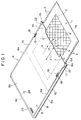
A printing sheet 1 is a substantially rectangular sheet
of about 200 microns in thickness made of a thermoplastic
resin such as polyethylene resin. Image data 2 is formed
with high precision in the form of relief of the order of
submicrons in a substantially rectangular region, shown with
diagonal hatching in Fig. 1, of the surface 1a of the
printing sheet 1. A row of sprocket holes 3 is formed along
each side, the left side and the right side, of the printing
sheet 1; the two rows are parallel and the sprocket holes 3
are spaced at a fixed pitch.
Next, with reference to Figs. 1 to 7, a printing sheet
jacket will be described.
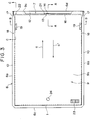
A printing sheet jacket 6 is substantially rectangular
and has the form of a flat bag with three sides 6a, 6b and 6c
closed in a substantial C-shape and a printing sheet
removal/insertion opening 7 provided at the fourth side 6d.
This printing sheet jacket 6 can be simply manufactured
by horizontally superposing a substantially rectangular base
sheet 8 and cover sheet 9 of thickness approximately 200
microns made of a thermoplastic resin such as polyethylene
resin or the like or PET resin sheet having its surface
coated with about 5 to 40µm of a readily thermally
decomposing material (for example a nitrocellulose compound)
and thermally sealing three of the sides 6a, 6b and 6c in a
substantial C-shape of a predetermined width (thermally
fusing together the base sheet 8 and the cover sheet 9 by
heating them while pressing them together).
The left and right side edges of the printing sheet
jacket 6 are formed as a left/right parallel pair of
belt-shaped roller press portions 10 of a predetermined
width.
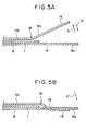
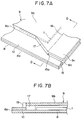
As shown in Fig. 6(A), the cover sheet 9 of the printing
sheet jacket 6 has a horizontal ceiling portion 9b formed
integrally atop a substantially C-shaped vertical portion 9a
which projects vertically upward along the inside of the
three edges 6a, 6b and 6c thermally sealed in a substantial
C-shape, and a flat printing sheet accommodating space 11 of
a height H1 greater than the thickness T1 of the printing
sheet 1 is formed between the ceiling portion 9b of the cover
sheet 9 and the base sheet 8.
The printing sheet 1 is accommodated in the printing
sheet accommodating space 11 with its front surface 1a facing
upward and can be removed from and reinserted into the
printing sheet accommodating space 11 through the printing
sheet removal/insertion opening 7 in the direction of the
arrows (a), a'.
During removal and reinsertion of the printing sheet 1
from and into the printing sheet accommodating space 11,
because the substantially C-shaped portion 9a of the cover
sheet 9 makes it possible for the height H1 of the printing
sheet accommodating space 11 to be made greater than the
thickness T1 of the printing sheet 1, removal and reinsertion
of the printing sheet 1 from and into the printing sheet
accommodating space 11 in the direction of the arrows (a), a'
can be carried out smoothly.
A cutaway 12 is formed from the central portion to the
left and right side portions of the opening end 9c, which is
the end portion of the cover sheet 9 at the printing sheet
removal/insertion opening 7 end, and an opening/closing flap
13 is formed integrally with the cover sheet 9 in the central
portion of the cutaway 12.
As shown in Fig. 4 and Fig. 5(B), this opening/closing
flap 13 is passed through a slot-shaped opening/closing flap
lock hole 14 formed in the central portion of the opening end
8a of the base sheet 8, and this blocks the printing sheet
removal/insertion opening 7 of the printing sheet jacket 6
and locks in the printing sheet 1 (prevents the printing
sheet 1 from coming out of the printing sheet jacket 6)
sheathed inside the printing sheet jacket 6.
A left/right parallel pair of slits 15 cut out of the
opening end 9c of the cover sheet 9 are formed in the cover
sheet 9 at the left and right sides of the printing sheet
removal/insertion opening 7, and the opening end 9c of the
cover sheet 9 can open and close easily across its entire
width in the direction of the arrows b, b' along a crease 16
connecting the deepest portions 15a of the left/right slits
15.
A left/right pair of taper portions 17 tapering off in
the printing sheet insertion direction (the direction of the
arrow a') for guiding printing sheet insertion are formed
integrally at the left and right sides of the printing sheet
removal/insertion opening 7 from the deepest portions 15a of
the left/right slits 15 to the left/right sides of the
vertical portion 9a.
Consequently, when the printing sheet 1 is inserted into
the printing sheet accommodating space 11 through the
printing sheet removal/insertion opening 7 of the printing
sheet jacket 6 in the direction of the arrow a', because the
left and right side portions of the printing sheet 1 are
guided by the left/right pair of taper portions 17, the
operation of inserting the printing sheet 1 into the printing
sheet accommodating space 11 in the direction of the arrow a'
can be carried out smoothly.
A left/right pair of jacket holding holes 18 passing
vertically through the base sheet 8 and the cover sheet 9 are
formed in the left/right pair of roller press portions 10 in
locations in the vicinity of the printing sheet
removal/insertion opening 7 of the printing sheet jacket 6.
Left/right pairs of slot-shaped sprocket access holes
19, 20 passing vertically through the ceiling portion 9b of
the cover sheet 9 and the base sheet 8 respectively are
formed in positions in the vicinity of the printing sheet
removal/insertion opening 7 of the printing sheet jacket 6
directly above and below sprocket holes 3 in the left and
right sides of the printing sheet 1 sheathed in the printing
sheet jacket 6.
Misloading (mis-insertion) detection holes 21, 22
constituting objects of detection of misloading detecting
means for detecting misloading (mis-insertion) of the
printing sheet jacket 6 into a printing sheet making machine
and a printing machine to be discussed hereinafter are formed
in the vicinity of the printing sheet removal/insertion
opening 7 of the printing sheet jacket 6 in left/right
positions asymmetrical with respect to the left-right
direction center of the printing sheet jacket 6. The
misloading detection hole 21 is formed to one side of the
opening/closing flap 13 and the misloading detection hole 22
is disposed above the centerline of one of the rows of
sprocket holes 3 in the printing sheet 1.
A bar code label 23 for identifying the type of the
printing sheet 1 sheathed inside the printing sheet jacket 6
(identifying its type in terms of whether or not it is a new
printing sheet and what image data 2 is engraved on it in
what colors, etc) is affixed to the upper side of the cover
sheet 9 of the printing sheet jacket 6. As necessary, an
observation hole 24 for identifying the above-mentioned type
of the printing sheet 1 visually is provided in the cover
sheet 9 of the printing sheet jacket 6.
Next, with reference to Figs. 8 and 9, a printing sheet
making and printing system will be described.
In this printing sheet making and printing system,
first, in a printing sheet making machine 27, image data 2
such as a photograph or the like is engraved in the form of
relief in the front surfaces 1a of 1 to 4 printing sheets 1.
These engraved 1 to 4 printing sheets 1 are then fed
into a printing machine 37, overprinting 1 to 4 times onto
cut paper 47 is carried out using the color by color image
data 2 on the surfaces 1a of the 1 to 4 printing sheets 1,
and printing of a photograph or the like is thereby
performed.
In this printing sheet making and printing system, by
the printing sheet 1 being sheathed in a printing sheet
jacket 6 while being handled before engraving, after
engraving, and before and after printing, from first to last,
the adhesion of dust and the like and the occurrence of
scratching on the surface 1a of the printing sheet 1 is
prevented.
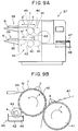
As shown in Fig. 8, the printing sheet making machine 27
is fitted with a jacket loading table 28 and a printing sheet
feed and eject device 29 disposed thereon. Inside the
printing sheet making machine 27 there are disposed a
printing cylinder 30 and a laser block 34 which shines a
laser beam CB emitted by a semiconductor laser 31 through a
collimator lens 32 and an objective lens 33 onto the surface
1a of a printing sheet wound on the periphery of the cylinder
30. The laser block 34 is reciprocated in the axial
direction of the cylinder 30 [perpendicular to the plane of
the drawing of Fig. 8(B)].
As shown in Fig. 9, the printing machine 37 is provided
with 1 to 4 jacket loading tables 38 and 1 to 4 printing
sheet feed and eject devices 39 for loading, feeding and
ejecting 1 to 4 printing sheet jackets 6, and inside the
printing machine 37 there are disposed the same number of
printing cylinders 40, pressure rollers 41 and ink units 45
comprising ink pans 42, ink rollers 43, and doctor blades 44,
etc. Four colors of water-type ink 46 such as cyan, magenta,
yellow and black are supplied color by color to the 4 ink
pans 42. The printing machine 37 is provided with a cut
paper tray 48 on which is stacked cut paper 47, the matter to
be printed, and inside the printing machine 37 is mounted a
cut paper circulating apparatus (not shown in the drawings)
for circulating the cut paper 47 to the 1 to 4 pressure
rollers 41 one after another. Fig. 9(A) shows a printing
machine provided with two jacket loading tables 38, two
printing sheet feed and eject devices 39, two cylinders 40,
two pressure rollers 41 and two ink units 45.
As shown in Fig. 8(A), a printing sheet jacket 6 in
which an unengraved printing sheet 1 is sheathed is loaded
horizontally in the direction of the arrow (a) onto the
jacket loading table 28 of the printing sheet making machine
27. When this is done, the printing sheet feed and eject
device 29 automatically pulls the printing sheet 1 out from
inside the printing sheet jacket 6 in the direction of the
arrow (a) and winds the printing sheet 1 onto the periphery
of the cylinder 30 inside the printing sheet making machine
27, as shown in Fig. 8(B).
In the printing sheet making machine, as shown in Fig.
8(B), so-called direct engraving, wherein the printing sheet
1 is rapidly rotated in the direction of the arrow c by the
cylinder 30 while the semiconductor laser 31 shines a laser
beam LB onto the surface 1a of the printing sheet 1 while the
laser block 34 is reciprocated in the axial direction of the
cylinder 30 and color by color image data 2 of a photograph
or the like is thereby engraved directly with high precision
in the form of relief of the order of submicrons in the
surface 1a of the printing sheet 1, is carried out on 1 to 4
printing sheets 1 one after another.
For this, digital information representing an image such
as a photograph is taken from a multimedia source such as a
photograph scanner or a digital VTR and electronically edited
in an image processing computer or the like, and digital
information for each of four colors such as cyan, magenta,
yellow and black is obtained. The 1 to 4 printing sheets 1
are then put through the printing sheet making machine one
after another and based on this color by color four-color
digital information color by color image data 2 for each of
the four colors is then separately engraved on the 1 to 4
printing sheets 1.
Each engraved printing sheet 1 is automatically removed
from the periphery of the cylinder 30 in the direction of the
arrow a' and reinserted into its printing sheet jacket 6 by
the printing sheet feed and eject device 29, whereby the
engraving step is finished. The printing sheet jacket 6 is
then removed from the jacket loading table 28 in the
direction of the arrow a' and loaded into the printing
machine 37.
As shown in Fig. 9(A), the 1 to 4 printing sheet jackets
6 containing the engraved printing sheets 1 of the different
colors engraved color by color in the engraving step are
severally loaded horizontally in the direction of the arrow
(a) onto the 1 to 4 jacket loading tables 38 of the printing
machine 37. When this is done, the printing sheet feed and
eject devices 39 automatically pull the printing sheets 1 out
of their printing sheet jackets 6 in the direction of the
arrow (a) and automatically wind them onto the peripheries of
the 1 to 4 cylinders 40 inside the printing machine 37, as
shown in Fig. 9(B).
Cut paper 47 from the cut paper tray 48 shown in Fig.
9(A) is circulated around the 1 to 4 pressure rollers 41 and
printing of the kind illustrated in Fig. 9(B) is carried out.
That is, while the cylinders 40 are rotated at high
speed in the direction d, the ink rollers 43 in contact with
the surfaces of the printing sheets 1 are rotated at high
speed in synchrony with the cylinders 40, water-type inks 46
of the different colors from the ink pans 42 are coated onto
the relief that is the image data 2 of the respective colors
on the printing sheets 1, and unnecessary ink 46 is scraped
off by the doctor blades 44. The pressure rollers 41, which
rotate at high speed in the direction of the arrow f in
synchrony with the cylinders 40, feed the cut paper 47 past
the cylinders 40 at high speed while pressing it against the
surfaces 1a of the printing sheets 1, and the color by color
image data 2 of a photograph or the like on the printing
sheets 1 prints a sequentially colored image 4 on the cut
paper 47 at high speed.
By this sequential overprinting of the color by color
image data 2 of a photograph or the like of the printing
sheets 1 by the cut paper 47 being sequentially circulated
around the 1 to 4 pressure rollers 41 it is possible to print
a sheet of color-printed matter on which the four colors
cyan, magenta, yellow and black are compounded. However,
one-color printing, two-color printing, three-color printing
and five or more color printing are also possible and are
achieved by adjusting the number of engraving steps and
printing steps according to the number of colors to be
printed.
The above-mentioned jacket loading tables 28 and 38, the
printing sheet feed and eject devices 29 and 39, and the
cylinders 30 and 40 of the printing sheet making machine 27
and the printing machine 37 are of identical construction.
The jacket loading table 28, the printing sheet feed and
eject device 29 and the cylinder 30 of the printing sheet
making machine 27 will now be described with reference to
Figs. 10 to 29.
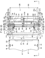
First of all, with reference to Figs. 10 to 13, the main
features of the printing sheet feed and eject device will be
described.
A table cover 51 is horizontally mounted on a horizontal
jacket loading table 28 and a printing sheet jacket 6 is
horizontally loaded into a horizontal jacket loading space 52
formed between these two onto the jacket loading table 28 in
the direction of the arrow (a) with its printing sheet
removal/insertion opening 7 end at the front. Left/right
side guides 53 for horizontally guiding the left and right
sides of the printing sheet jacket 6 are formed integrally
with the table cover 51 at the left and right sides thereof.
The printing sheet feed and eject device 29 is mounted
above the table cover 51 of the jacket loading table 28; this
printing sheet feed and eject device 29 comprises left/right
symmetrical pairs of jacket and printing sheet pulling in
devices 55 and jacket holding devices 56, and is also
provided with jacket central and side flap opening devices
57a and 57b.
A drive shaft 58, a camshaft 59 and a sprocket shaft 60
are disposed horizontally crossing over the table cover 51 in
the left-right direction and are mounted on a left/right pair
of brackets 61. A motor 62 and a gear train 63 for
reversibly rotationally driving the drive shaft 58 and a
motor 64 and a gear train 65 for reversibly rotationally
driving the camshaft 59 are mounted above the table cover 51.
Three left/right pairs of cam mechanisms 66, 67 and 68, six
cam mechanisms in total, are mounted at the left and right
ends of the camshaft 59, and a cam mechanism 69 is mounted at
the central portion of the camshaft 59.
The left/right pairs of jacket and printing sheet
pulling in devices 55 and jacket holding devices 56 and the
jacket central and side flap opening devices 57a and 57b are
driven by the motors 62 and 64, the gear trains 63 and 65,
the drive shaft 58, the camshaft 59 and the cam mechanisms
66, 67, 68 and 69 in the manner described hereinafter.
A number of sensors S1 to S8 constituting a controller
for controlling the jacket and printing sheet pulling in
devices 55, the jacket holding devices 56 and the jacket
central and side flap opening devices 57a and 57b so that
they operate sequentially based on predetermined sequences
are provided. As shown in Fig. 12, the sensors S1 to S6 each
consist of a light emitting device LD and a light receiving
device PD disposed so as to perform light detection
vertically through the jacket loading table 28 and the table
cover 51. The sensors S7 and S8 comprise photocouplers which
perform detection on a pair of slit discs 70 mounted on the
left and right ends of the camshaft 59. A left/right pair of
jacket stoppers 71 are mounted on the left and right sides of
the arrow (a) direction end of the jacket loading table 28.
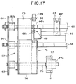
Next, with reference to Figs. 14 to 17, the jacket and
printing sheet pulling in devices will be described.
The left/right jacket and printing sheet pulling in
devices 55 are constructed left/right symmetrically and are
provided with a left/right pair of seesaw-style pivoting arms
76 each made up of first and second arms 73 and 74 mounted
pivotally in the direction of the arrows h, h' on the left
and right end portions of the drive shaft 58, which doubles
as a supporting shaft for them, and limiter springs 75
consisting of tension springs or the like which pull the
first and second arms 73 and 74 toward each other.
A left/right pair of drive rollers 77, which are jacket
pulling in means, are rotatably mounted via a left/right pair
of horizontal roller shafts 78 on the left/right pair of
second arms 74 on the arrow a' direction side of the drive
shaft 58. The left/right pair of drive rollers 77 comprise
high friction rollers such as rubber rollers and a left/right
pair of torque limiters 77a are incorporated therein.
A left/right pair of pinch rollers 79 are rotatably
mounted via a horizontal roller shaft 80 on the underside of
the jacket loading table 28 directly below and facing the
pair of drive rollers 77. A left/right pair of long holes 81
are formed in the table cover 51 and in the jacket loading
table 28 to allow the left/right pairs of drive rollers 77
and pinch rollers 79 to project therethrough.
The left and right ends of the sprocket shaft 60 are
rotatably attached to the left/right pair of first arms 73 on
the direction (a) side of the drive shaft 58. A left/right
pair of sprockets 82, which are printing sheet pulling in
means, are mounted on the left and right ends of the sprocket
shaft 60. A left/right pair of long holes 83 are formed in
the table cover 81 and the jacket loading table 28 to allow
the left/right pair of sprockets 82 to project therethrough.
Left/right pairs of driven gears 85 and 86 respectively
mounted on the left/right pair of roller shafts 78 and the
left and right end portions of the sprocket shaft 60 mesh
with the front and rear sides of drive gears 84 mounted on
the left/right end portions of the drive shaft 58, and these
gears 84, 85 and 86 constitute a drive mechanism. Torque
limiters 82a are provided between the left/right pair of
driven gears 86 and the left/right end portions of the
sprocket shaft 60.
A left/right pair of cam mechanisms 66, which are
control mechanisms, mounted on the left/right end portions of
the camshaft 59, each comprise a cam 66a mounted on the
camshaft 59, a driven roller 66b, which is a cam follower,
rotatably mounted on the first arm 73, and a cam spring 66c,
consisting of a tension spring or the like, which
rotationally urges the first arm 73 in the direction of the
arrow h and presses the driven roller 66b onto the upper
portion of the periphery of the cam 66a.
The first and second arms 73 and 74 are urged toward
each other in the direction of the arrows h, h' by the
limiter spring 75 and have their positions with respect to
each other restricted by a stopper 87 disposed between them.
The first arm 73, rotationally urged by the cam spring 66c in
the direction of the arrow h about the camshaft 58, has its
position restricted by being caused by a rubber cushion 88 to
abut with the top of a stopper 89 mounted on the table cover
51.
When the drive shaft 58 is forward/reverse rotationally
driven by the motor 62, shown in Fig. 10, via the gear train
63, the left/right pairs of rollers 77 and sprockets 82 of
the left/right pair of jacket and printing sheet pulling in
devices 55 are forward/reverse rotationally driven
simultaneously.
That is, as shown in Figs. 14 to 17, the rotational
drive of the drive shaft 58 is transmitted to the roller
shaft 78 and the sprockets 82 via the drive mechanism made up
of the drive gears 84 and the driven gears 85 and 86, and the
left right pairs of drive rollers 77 and sprockets 82 are
thereby forward/reverse rotationally driven simultaneously.
When the camshaft 59 is forward/reverse rotationally
driven by the motor 64, shown in Fig. 10, via the gear train
67, the left/right pairs of drive rollers 77 and sprockets 82
of the left/right pair of jacket and printing sheet pulling
in devices 55 are reversibly raised in the direction of the
arrows h, h' by the left/right pair of cam mechanisms 66.
That is, as shown in Figs. 14 and 16, when the
left/right pair of cams 66a of the cam mechanisms 66 are at
the cam angle 0°, the pivoting arms 76 are rotationally urged
about the drive shaft 58 in the arrow h direction by the cam
springs 66c, and while the left/right pair of drive rollers
77 are raised in the arrow h direction to above the table
cover 51, the left/right pair of sprockets 82 are lowered in
the arrow h direction to below the table cover 51.
Next, as shown in Fig. 15, when the cams 66a of the cam
mechanisms 66 are at a the cam angle 180°, these cams 66a
push the cam driven rollers 66b upward, the pivoting arms 76
are pivoted about the drive shaft 58 against the resistance
of the cam springs 66c, and while the left/right pair of
drive rollers 77 are lowered in the arrow h' direction to
below the table cover 51 the left/right pair of sprockets 82
are raised in the arrow h' direction to above the table cover
51.
The cam angle 0° and 180° positions of the cam 66a are
detected by the sensor S7.
As shown in Fig. 15, when the left/right pair of drive
rollers 77 are lowered in the arrow h' direction, as will be
further discussed hereinafter, these left/right drive rollers
press elastically on the left/right pair of pinch rollers 79,
against the resistance of the limiter springs 75, through the
left/right pair of roller press portions 10 of the printing
sheet jacket 6 loaded onto the jacket loading table 28. In
this state, the rotational force of the left/right pair of
drive rollers 77 is transmitted to the printing sheet jacket
6, and any forward/reverse rotation of the left/right pair of
drive rollers 77 causes the printing sheet jacket 6 to move
on the jacket loading table 28 in the direction of the arrows
(a), a'.
As shown in Fig. 16, when the left/right pair of
sprockets 82 are lowered in the arrow h direction, as will be
further discussed hereinafter, these left/right sprockets 82
enter the left/right pair of sprocket access holes 19, 20 in
the printing sheet jacket 6 loaded onto the jacket loading
table 28, and these left/right sprockets 82 engage with the
sprocket holes 3 in the left and right sides of the printing
sheet 1. In this state, the rotational force of the
left/right pair of sprockets 82 is transmitted to the
printing sheet 1 and any forward/reverse rotation of the
left/right pair of sprockets 82 causes the printing sheet 1
to move in the printing sheet jacket 6 in the direction of
the arrows (a), a'.
With these jacket and printing sheet pulling in devices
55, because the drive rollers 77 and the sprockets 82 are
reversibly raised and lowered by the cam mechanisms 66
driving the seesaw-style pivoting arms 76 to pivot one way
(the arrow h direction) or the other (the arrow h'
direction), it is possible to raise and lower the two types
of actuator that are the drive rollers 77 and the sprockets
82 with the one motor 64. Also, because the drive rollers 77
and the sprockets 82 are simultaneously forward/reverse
rotationally driven by the single drive shaft 58 via the
drive mechanism made up of the drive gears 84 and the driven
gears 85 and 86, the two types of actuator that are the drive
rollers 77 and the sprockets 82 can be simultaneously
forward/reverse rotationally driven by the single motor 62.
Consequently, the construction of these jacket and
printing sheet pulling in devices 55 is simple, spacesaving
and low cost.
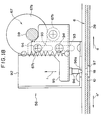
Next, with reference to Figs. 18 to 20, the jacket
holding devices will be described.
A left/right pair of jacket holding devices 56 are of
left/right symmetrical construction and comprise a left/right
pair of vertical slider mounting plates 92 mounted on the
table cover 51 and a left/right pair of sliders 95 mounted on
side surfaces of these slider mounting plates 92 by way of a
plurality of guide holes 93 and guide pins 94 in such a way
that they can move vertically in the direction of the arrows
i, i'.
A left/right pair of holding pins 96, which are jacket
holding means, are fixed to the undersides of the left/right
pair of sliders 95 and project perpendicularly downward
therefrom.
A left/right pair of cam mechanisms 67, which are drive
mechanisms for raising and lowering the left/right pair of
holding pins 96 in the direction of the arrows i, i', are
each made up of a cam 67a mounted on the camshaft 59, a cam
driven roller 67b, which is a cam follower, rotatably mounted
on the slider 95, and a cam spring 67c, consisting of a
tension spring or the like, which urges the slider 95 upward
in the arrow i direction and presses the cam driven roller
67b against the underside of the periphery of the cam 67a.
A taper 96a is formed on the lower end of each of the
left/right pair of holding pins 96. Holes 97 are formed in
the table cover 51 and the jacket loading table 28 to allow
the left/right pair of holding pins 96 to pass therethrough.
When the camshaft 59 is forward/reverse rotationally
driven one way by the motor 64, shown in Fig. 10, via the
gear train 67, the left/right cam mechanisms 67 cause the
left/right pairs 96 of the left/right jacket holding devices
56 to ascend or descend in the direction of the arrows i, i'.
That is, when the cams 67a of the cam mechanisms 67 are
at the cam angle 180°, as shown in Fig. 18, the left/right
pair of sliders 95 have been simultaneously lifted up by the
cam springs 67c and the left/right pair of holding pins 96
have been simultaneously raised in the arrow i direction to
above the table cover 51.
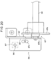
Next, when the cams 67a of the cam mechanisms 67 are at
the cam angle 0°, as shown in Fig. 19, the cam driven rollers
67b have been pushed down by these cams 67a against the
resistance of the cam springs 67c and the left/right pair of
sliders 95 have been simultaneously lowered in the arrow i'
direction. When the left/right pair of holding pins 96 are
simultaneously lowered in the arrow i' direction to below the
table cover 51, as will be further described hereinafter,
these left/right holding pins 96 enter vertically from above
into the left/right pair of jacket holding holes 18 in the
printing sheet jacket 6 loaded onto the jacket loading table
28 and hold the printing sheet jacket 6 in a fixed position
on the jacket loading table 28.
At this time, because the tapers 96a are provided on the
lower ends of the left/right pair of holding pins 96, even if
the printing sheet jacket 6 is slightly out of the above-mentioned
fixed position, the guiding action of the tapers
96a serves to automatically bring the printing sheet jacket
6 into the fixed position as the holding pins 96 descend.
Next, with reference to Figs. 21 to 25, the jacket
central flap opening device 57a will be described.
This jacket central flap opening device 57a is a device
for opening the flap of the central part of the opening end
9c of the cover sheet 9 of the printing sheet jacket 6.
This jacket central flap opening device 57a has a
vertical flap opening arm mounting plate 100 mounted on the
central portion of the table cover 51, a flap opening arm 102
and a cam driven arm 103 mounted pivotally in the direction
of the arrows j, j' on a side surface of the flap opening arm
mounting plate 100 via a horizontal supporting shaft 101, and
a central flap opening suction pad 104, which is central flap
opening means, and a central pushing pin 105, which is
central pushing means, mounted on the underside of the end
portion of the flap opening arm 102 and projecting
perpendicularly therefrom.
The central cam mechanism 69, which is a control
mechanism, mounted at the center of the camshaft 59, is made
up of a cam 69a mounted on the camshaft 59, a cam driven
roller 69b, which is a cam follower, rotatably mounted on the
cam driven arm 103, and a cam spring 69c, consisting of a
tension spring or the like, which at all times pushes the cam
driven roller 69b against the periphery of the cam 69a.
The flap opening arm 102 is mounted on the support shaft
101 in such a way that it can pivot in the direction of the
arrows j, j', and the cam driven arm 103 is mounted on this
flap opening arm 102 via a plurality of adjustment screws 106
in such a way that its length in the direction of the arrows
k, k' is adjustable. By adjusting the length in the
direction of the arrows k, k' of the cam driven arm 103 with
respect to the flap opening arm 102, it is possible to adjust
the opening stroke in the directions of the arrows j, j'
through which the central flap opening suction pad 104 is
moved by the cam mechanism 69.
Two holding suction pads 107 and 108, which are central
holding means, are vertically mounted under the jacket
loading table 28 in positions directly below the central flap
opening suction pad 104 and the central pushing pin 105
respectively. The central flap opening suction pad 104 and
the central holding suction pads 107 and 108 are constructed
as vacuum suction-gripping means connected to a vacuum pump
(not shown in the drawings).
When the camshaft 59 is forward/reverse driven in one
direction by the motor 64, shown in Fig. 10, via the gear
train 67, the jacket central flap opening device 57a is
driven by the central cam mechanism 69.
That is, when the camshaft 59 rotates the cam 69a of the
central cam mechanism 69 in the direction of the arrow from
the cam angle 180° shown in Fig. 21 toward the cam angle 0°
shown in Fig. 24, the flap opening arm 102 is caused to pivot
up and down in the direction of the arrows b, b' by the cam
driven roller 69b which is at all times pushed against the
periphery of the cam 69c by the cam spring 69c and rolls
along the periphery of the cam 69a.
When this happens, when the cam 69a is at the cam angle
180°, as shown in Fig. 21, as will be further described
hereinafter the central flap opening suction pad 104 and the
central pushing pin 105 are being held up in the arrow b
direction and are clear of the printing sheet jacket 6.
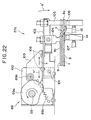
Next, when the cam 69b has been rotated to the position
in which it is shown in Fig. 22, as will be further described
hereinafter, the central flap opening suction pad 104 is
pushed by the flap opening arm 102 from the arrow b'
direction down onto the opening end 9c of the cover sheet 9
of the printing sheet jacket 6 loaded into the above-mentioned
fixed position on the jacket loading table 28 and
the opening end 8a of the base sheet 8 of the printing sheet
jacket 6 is pushed by the central flap opening suction pad
104 and the central pushing pin 105 in the arrow b' direction
down onto the pair of central holding suction pads 107 and
108.
At this time, the central flap opening suction pad 104
and the central holding suction pads 107 and 108 are caused
by suction from the vacuum pump to suction-grip the central
portions of the upper side of the cover sheet 9 and the
underside of the base sheet 8 respectively.
Then, as the cam 69a is rotated to the position in which
it is shown in Fig. 23, the central flap opening suction pad
104 is lifted by the flap opening arm 102 through a large
opening stroke 1 in the arrow b direction and the opening
end 9c of the cover sheet 9 suction-gripped by the central
flap opening suction pad 104 is opened in the arrow b
direction through the large opening stroke 1. At this time,
as shown in Figs. 1, 2 and 7, because the left/right pair of
slits 15 are formed at the left and right sides of the
opening end 9c of the cover sheet 9, the opening end 9c of
the cover sheet 9 can be easily opened in the arrow b
direction through the large opening stroke 1. The opening
end 8a of the base sheet 8 is suction-gripped and kept held
in its horizontal position by the central holding suction
pads 107 and 108.
At this time, with the opening end 8a of the base sheet
8 firmly held by the strong suction force of the two central
holding suction pads 107 and 108, because the opening end 9c
of the cover sheet 9 is opened by the central flap opening
suction pad 104 in the arrow b direction through the large
stroke 1, the opening/closing flap 13 is reliably and easily
pulled in the arrow b direction out of the opening/closing
flap lock hole 14. By the opening/closing flap 13 being
pulled out of the opening/closing flap lock hole 14, the
printing sheet removal/insertion opening 7 is opened.
Next, as the cam 69a is rotated to the cam angle 0°
position shown in Fig. 24, as will be further discussed
hereinafter, the flap opening arm 102 returns a little in the
arrow b' direction and returns the opening end 9c of the
cover sheet 9 suction-gripped by the central flap opening
suction pad 104 in the arrow b' direction a little to a
predetermined opening stroke 2 wherein the cover sheet 9 is
unstressed, and the printing sheet removal/insertion opening
7 is held open to a predetermined extent.
Next, with reference to Figs. 26 to 29, the jacket side
flap opening device will be described.
This jacket side flap opening device 57b is a device for
opening the left and right side portions of the opening end
9c of the cover sheet 9 of the printing sheet jacket 6 and is
of left/right symmetrical construction.
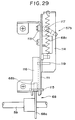
The jacket side flap opening device 57b comprises a
left/right pair of vertical flap opening arm mounting plates
111, a left/right pair of circular arcuate holes 112 formed
in the left/right pair of flap opening arm mounting plates
111, a left/right pair of flap opening arms 114 mounted via
left/right pairs of rollers 113 on side surfaces of the
left/right pair of flap opening arm mounting plates 111 in
such a way that they can move circularly along the left/right
pair of circular arcuate holes 112 in the direction of the
arrows n, n', a left/right pair of drive arms 116 mounted on
the opposite side surfaces of the left/right pair of flap
opening arm mounting plates 111 from the left/right pair of
flap opening arms 114 at their upper ends via a left/right
pair of support shafts 115 in such a way that they can pivot
in the direction of the arrows o, o', and a left/right pair
of side flap opening suction pads 117, which are side flap
opening means, mounted perpendicularly on the undersides of
the ends of the left/right pair of flap opening arms 114.
Here, the left/right pair of circular arcuate holes 112
are formed in circular arcs of radius of curvature R with the
crease line 16 of the opening end 9c of the cover sheet 9 as
a virtual center. Therefore, the left/right pair of flap
opening arms 114, engaged with these circular arcuate holes
112 via the pairs of rollers 113, move circularly along these
circular arcuate holes 112 in the direction of the arrows n,
n' with the crease line of the opening end 9c of the cover
sheet 9 of the printing sheet jacket 6 as a virtual center.
A left/right pair of side cam mechanisms 68, which are
control mechanisms, mounted at the left and right end
portions of the camshaft 59, each comprise a cam 68a mounted
on the camshaft 59, a cam driven roller 68b, which is a cam
follower, rotatably mounted on the drive arm 116, and a cam
spring 68c, consisting of a tension spring or the like, which
at all times pushes the cam driven roller 68b against the
periphery of the cam 68a. The lower ends of the left/right
pair of drive arms 116 are linked to the left/right pair of
flap opening arms 114 via link pins 119 mounted on the drive
arms 116 and passing through openings 118 in the left/right
pair of opening arm mounting plates 111 into linking holes
120 formed in the flap opening arms 114.
A left/right pair of side holding suction pads 121,
which are side holding means, are perpendicularly mounted
underneath the jacket loading table 28 and directly below the
left/right pair of side flap opening suction pads 117. The
left/right pairs of side flap opening suction pads 117 and
side holding suction pads 121 are constructed as vacuum
suction-gripping means connected to a vacuum pump.
When the camshaft 59 is forward/reverse rotationally
driven in one way by the motor 64, shown in Fig. 10, via the
gear train 67, the jacket side flap opening mechanism 57b is
driven by the left/right pair of side cam mechanisms 96.
That is, when the cam 68a of each cam mechanism 68 is
rotated in the direction of the arrow by the camshaft 59 from
the cam angle 180° shown in Fig. 26 toward the cam angle 0°,
the flap opening arm 114 is caused to reciprocate in the
direction of the arrows n, n' via the drive arm 116 by the
cam driven roller 68b which is at all times pressed against
the periphery of the cam 68a by the cam spring 68c and rolls
around the periphery of the cam 68a.
However, at this time, the pair of rollers 113 of the
opening arm 114 move circularly in the circular arcuate holes
112 in the direction of the arrows n, n' and the side flap
opening suction pads 117 consequently move circularly in the
direction of the arrows n, n' with the hereinafter discussed
crease 16 of the cover sheet 9 of the printing sheet jacket
6 as a virtual center.
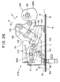
As shown in Fig. 26, when the cam 68a is at cam angle
180°, the left/right pair of side flap opening suction pads
117 are lifted in the arrow b direction above the table cover
51.
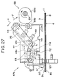
Next, when the cam 68a has been rotated to the position
in which it is shown in Fig. 27, as will be further discussed
hereinafter, the left/right pair of side flap opening suction
pads 117 are pressed down in the arrow b' direction by the
flap opening arms 114 onto the left and right side portions
of the opening end 9c of the cover sheet 9 of the printing
sheet jacket 6 loaded in the above-mentioned fixed position
on the jacket loading table 28, and also the left/right side
portions of the opening end 8a of the base sheet 8 of the
printing sheet jacket 6 are pushed by the left/right pair of
side flap opening suction pads 117 down onto the left/right
pair of side holding suction pads 121.
At this time, the left/right pair of side flap opening
suction pads 117 and the left/right pair of side holding
suction pads 121 are caused by the suction force of the
vacuum pump to suction-grip the left and right side portions
of the cover sheet 9 and the base sheet 8.
Next, when the cam 68a is rotated to the position in
which it is shown in Fig. 28, the left/right pair of side
flap opening suction pads 117 are lifted upward by the
opening arms 114 by the same amount as the opening stroke 2
shown in Fig. 24, and the opening end 9c of the cover sheet
9 suction-gripped by the left/right pair of side flap opening
suction pads 117 is opened upward through just the opening
stroke 2. The left and right side portions of the opening
end 8a of the base sheet 8 are suction-gripped and kept held
horizontal by the left/right pair of side holding suction
pads 121.
At this time, as shown in Figs. 1, 2 and 7, because the
left/right pair of slits 15 are formed in the left and right
sides of the opening end 9c of the cover sheet 9, and because
the left/right pair of side flap opening suction pads 117
move circularly about the crease 16 in the opening end 9c of
the cover sheet 9 as a virtual center, the cover sheet is
smoothly opened across its entire width about the crease 16.
By the side flap opening suction pads 117 being made to move
circularly about the crease 16 in the cover sheet 9 as a
virtual center, it is possible to prevent slippage of the
printing sheet jacket 6 during opening of the cover sheet 9;
as a result, the opening end 9c of the cover sheet 9 can be
opened unforcedly and reliably. The printing sheet
removal/insertion opening 7 is opened uniformly across its
entire width by this opening action.
The positions of the central cam mechanism 69 and the
side cam mechanisms 68 when the cams 69a, 68a are at the cam
angles 180° and 0° are detected by the sensor S8.
The cams 66a to 69a of the cam mechanisms 66 to 69 are
set to be at cam angle 0° before the start of printing sheet
feeding.
Then, as shown in Figs. 10 to 12, an operator manually
loads a printing sheet jacket 6 from its printing sheet
removal/insertion opening 7 end in the arrow g direction into
the jacket loading space 52 between the jacket loading table
28 and the table cover 51, and the insertion of the printing
sheet jacket 6 is detected by the sensors S1 and S2.
Then, as shown in Fig. 14, when the printing sheet
jacket 6 has passed between the drive rollers 77 and the
pinch rollers 79, based on detection by the sensor S2, the
motor 64 is driven to rotate forward and the cams 66a to 69a
of the cam mechanisms 66 to 69 are rotated from the cam angle
0° to the cam angle 180°.
When this happens, as shown in Figs. 6 to 15, the
left/right pair of drive rollers 77 are pushed down onto the
left/right pair of roller press portions 10 of the printing
sheet jacket 6 and, as shown in Figs. 15 and 18, the
left/right pair of sprockets 82 and the holding pins 96 which
would otherwise obstruct the insertion of the printing sheet
jacket 6 are withdrawn to above the jacket loading space 52.
Next, the motor 62 is driven to rotate forward and, a
shown in Fig. 15, the rotation of the left/right pair of
drive rollers 77 in the direction of the arrow automatically
pulls the printing sheet jacket 6 into the jacket loading
space 52 in the arrow (a) direction.
When the printing sheet jacket 6 has been pulled in the
arrow (a) direction as far as the above-mentioned fixed
position, the left and right side portions of the opening end
8a of the base sheet 8 abut with the left/right pair of
jacket stoppers 71 and the printing sheet jacket 6 is
stopped; at this time, the slip torque of the left/right pair
of torque limiters built into the left/right pair of drive
rollers 77 ensures that the printing sheet jacket 6 abuts
with the left/right pair of jacket stoppers 71 from the arrow
(a) direction and thereby correctly positions the printing
sheet jacket 6.
When the sensors S3 and S4 detect the completion of the
automatic pulling in of the printing sheet jacket 6 to the
above-mentioned fixed position and that the printing sheet
jacket 6 is parallel with respect to the left/right pair of
jacket stoppers 71, the motor 62 is automatically stopped.
While the printing sheet jacket 6 is being automatically
pulled in, the sensor S5 detects the presence or otherwise of
the misloading detection hole 21 formed in a left/right
asymmetrical position in the printing sheet jacket 6, and
top/bottom and front/rear misloading (mis-insertion) of the
printing sheet jacket 6 can thereby be detected. When the
printing sheet jacket 6 has been misloaded, the left/right
pair of drive rollers 77 are immediately driven to rotate in
reverse and automatically eject the printing sheet 6 in the
arrow a' direction, or the fact that the printing sheet
jacket 6 has been incorrectly loaded is made known to the
operator by some kind of display or the like.
When the printing sheet jacket 6 has been automatically
pulled in as far as the above-mentioned fixed position, as
shown in Fig. 28, the crease 16 in the cover sheet 9 is
correctly positioned at the center of the radius of curvature
of the left/right pair of circular arcuate holes 112.
After the completion of the automatic pulling in of the
printing sheet jacket 6 to the above-mentioned fixed
position, the vacuum pump is activated and the motor 64 is
driven to rotate in reverse to change the cam angle of the
cams 66a to 69a of the cam mechanisms 66 to 69 from 180° to
0°.
By this action, as shown in Figs. 24 and 28, the opening
end 9c of the cover sheet 9 is unforcedly and smoothly opened
across its entire width about the crease 16, and the printing
sheet removal/insertion opening 7 is opened across its entire
width. Then, as shown in Fig. 16, the left/right pair of
drive rollers 77 are withdrawn to above the printing sheet
jacket 6. Then, as shown in Fig. 19, the left/right pair of
holding pins 96 are inserted into the left/right pair of
jacket holding holes 18 in the printing sheet jacket 6 and
the printing sheet jacket 6 is thereby held in the above-mentioned
fixed position. As shown in Figs. 2, 6 and 16, the
left/right pair of sprockets 82 engage with the sprocket
holes 3 in the left and right sides of the printing sheet 1
inside the printing sheet jacket 6.
Next, the motor 62 is again driven to rotate and, as
shown in Fig. 16, the rotational force of the left/right pair
of sprockets 82 in the direction of the arrow drives the
sprocket holes 3 in the direction of the arrow and the
printing sheet 1 is automatically pulled out from inside the
printing sheet jacket 6 in the direction of the arrow (a).
At this time, the sensor S6 counts the number of
sprocket holes 3 and the extent to which the printing sheet
1 has been pulled out in the arrow (a) direction is thereby
detected. This sensor S6 can also detect the misloading
detection hole 22 in the printing sheet jacket 6.
When the printing sheet 1 has been pulled out of the
printing sheet jacket 6 in the arrow (a) direction as far as
a predetermined position, as shown in Figs. 11 and 12, the
cylinder 30 is driven to rotate in the direction of the arrow
and sprocket pins 30a provided around the peripheries of both
ends of the cylinder 30 engage with the sprocket holes 3 in
the left and right sides of the printing sheet 1 and, as
shown by dotted lines in Figs. 11 and 12, the printing sheet
1 is automatically wound onto the periphery of the cylinder
30. The printing sheet 1 ends up completely out from inside
the printing sheet jacket 6 and wound around the cylinder 30,
as shown in Figs. 8(B) and 9(B).
During opening of the printing sheet removal/insertion
opening 7 of the printing sheet jacket 6, the cover sheet 9
is opened using the suction force of a vacuum pump connected
to the central and side flap opening suction pads 104 and
117; by detecting the degree of vacuum created by the vacuum
pump in the central and side flap opening suction pad 104 and
117 system with a pressure sensor, indirect detection of
whether or not the cover sheet 9 has opened is carried out.
When the printing sheet 1 is to be ejected, the vacuum
pump is operating, the cams 66a to 69a are set to cam angle
66a to 69a, the cover sheet 9 of the printing sheet jacket 6
held in the jacket loading space 52 is open, and the printing
sheet removal/insertion opening 7 is standing by still open
across its entire width.
The printing sheet 1 is then automatically returned from
the cylinder 30 into the printing sheet jacket 6 through the
printing sheet removal/insertion opening 7 in the arrow a'
direction. At this time, because the motor 62 is driven to
rotate in reverse and the left/right pair of sprockets 82 are
thereby driven to rotate in reverse, the left/right pair of
sprockets 82 drive the sprocket holes 3 in the left and right
sides of the printing sheet 1, and the printing sheet 1 is
automatically returned in the arrow a' direction into the
printing sheet jacket 6.
At this time, the speed of rotation of the left/right
pair of sprockets 82 is made slightly higher than the speed
at which the cylinder 30 reels out the printing sheet 1; this
difference in speed is absorbed by the torque limiters 82a of
the sprocket shaft 60, and thereby the printing sheet 1 can
be returned in the arrow a' direction into the printing sheet
jacket 6 without any slackness.
At this time, the left/right pair of taper portions 17
in the printing sheet jacket 6, shown in Figs. 1, 2, 3 and 7,
guide the left and right side portions of the printing sheet
1 and consequently the printing sheet 1 can be inserted into
the printing sheet jacket 6 in the arrow a' direction
smoothly.
When the printing sheet 1 has been returned to inside
the printing sheet jacket 6, the sensor S5 detects this and
the motor 62 is automatically stopped. The motor 64 is then
driven to rotate forward and the cams 66a and 69a are set to
the cam angle 180° whereby the left/right pair of drive
rollers 77 are pushed down onto the printing sheet jacket 6
and the left/right pair of holding pins 96 and the sprockets
82 are withdrawn to above the printing sheet jacket 6.
The motor 62 is then driven to rotate in reverse, and
the printing sheet jacket 6 is automatically ejected from
inside the jacket loading space 52 by a certain fixed amount
in the arrow a' direction. The completion of the ejection of
the printing sheet jacket 6 in the direction a' is detected
by the sensor S2, and the motor 62 is automatically stopped.
After that, when an operator manually pulls the printing
sheet jacket 6 out of the jacket loading space 52 in the
arrow a' direction and this is detected by the sensor S1, the
motor 64 again sets the cams 66a to 69a to the cam angle 0°
and thereby returns the apparatus to the initial printing
sheet feeding state. At this time, until the sensor S1
detects that the printing sheet jacket 6 has been removed
manually, the apparatus goes into a standby state, and even
if the printing sheet jacket 6 is manually inserted in the
arrow (a) direction again automatic printing sheet feeding
will not be carried out.
As described above, in this electronic gravure printing
system, because the system can be operated without the
operator touching the printing sheet 1 at all, the adhesion
of dust and the like and the occurrence of scratching on the
surface 1a of the printing sheet 1 on which the image data 2
is formed can be completely prevented and stable printed
matter can be obtained. Also, by developing this system, an
electronic gravure printing system which can be run unmanned
can easily be realized.
The devices for winding the printing sheet 1 onto the
cylinders 30 and 40 of the printing sheet making machine 27
and the printing machine 37 discussed above are of identical
construction. The printing sheet winding device 251 of the
printing sheet making machine 27 will now be described, with
reference to Figs. 30 to 68.
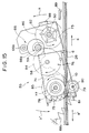
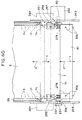
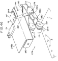
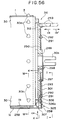
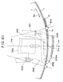
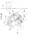
First, with reference to Figs. 49, 67 and 68, the drive
mechanism 229 of the cylinder 30 will be described.
A left/right pair of cylinder support frames 253 are
perpendicularly mounted apart from each other on a chassis
252, and a cylinder 30 is disposed horizontally between these
cylinder support frames 253. The axial direction (the
left-right direction) ends of a horizontal shaft 30b fixed at
the center of the cylinder 30 are rotatably mounted on the
left/right pair of cylinder support frames 253 via a
left/right pair of bearings (not shown in the drawings). The
above-mentioned jacket loading table 28 is mounted
horizontally between the left/right pair of cylinder support
frames 253, and the forward end of the jacket loading table
28 in the arrow (a) direction is in the vicinity of the upper
part of the cylinder 30.
The cylinder drive mechanism 229 consists of a drive
motor 230, which is cylinder rotational drive means, mounted
on the chassis 252 and linked by a belt transmission
mechanism 231 to one end of the shaft 30b. A rotary encoder
232, which is cylinder position detecting means, is directly
coupled to the other end of the shaft 30b and is mounted on
a side surface of one of the cylinder support frames 253.
Accordingly, the arrangement is such that the cylinder
30 is freely forward/reverse rotationally driven in the
direction of the arrows c, c' by the drive motor 230,
detection of the position of the cylinder 30 in the direction
of the arrows c, c' is performed by the rotary encoder 232,
and the cylinder 30 can be stopped at designated positions.
A row of sprocket pins 30a is provided at each end of
the periphery of the cylinder 30; the sprocket pins 30a of
both rows are spaced at the same pitch and are located in
identical positions around the periphery of the cylinder 30.
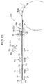
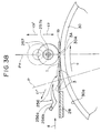
A printing sheet winding device 251 which will be
further discussed hereinafter is mounted between the
left/right pair of cylinder support frames 253. During
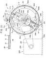
printing sheet feeding, as shown in Fig. 67, a printing sheet
1 automatically pulled out of a printing sheet jacket 6
loaded onto the jacket loading table 28 in the arrow (a)
direction by the printing sheet feed and eject device 29
discussed above is automatically wound in the arrow c
direction onto the periphery of the cylinder 30 by the two
rows of sprocket pins 30a on the cylinder 30, as shown in
Fig. 68, in a manner discussed hereinafter.
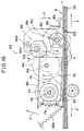
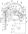
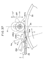
After this printing sheet winding, as shown in Fig. 68,
while the cylinder is rotated at high speed in the arrow c
direction, as discussed above, a laser beam is shone on the
surface of the printing sheet 1 by a laser block 34, and the
laser block 34 is reciprocated horizontally in the direction
of the arrows s, s' along the axis of the cylinder 30, and
the engraving step is thereby carried out.
A laser block transport mechanism 223 moves a laser
block transport plate 224 on which the laser block 34 is
mounted in the direction of the arrows s, s' by means of a
feed screw 227 forward/reverse rotationally driven by a drive
motor 226 mounted at one end of the feed screw 227 while
guiding the laser block transport plate 224 between a pair of
slide guides 225 parallel with the axis of the cylinder 30.
A rotary encoder 228 which detects the position in the
direction of the arrows s, s' of the laser block 34 is
directly coupled to the other end of the feed screw.
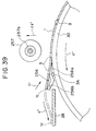
During printing sheet ejection after engraving, as will
be further discussed hereinafter, the printing sheet 1 is
automatically unwound from the periphery of the cylinder 30
in the arrow c' direction and is automatically conveyed in
the arrow a' direction into the printing sheet jacket 6.
The printing sheet winding device 251 will now be
described in detail.
First, as shown in Figs. 30 to 34, the two rows of
sprocket pins 30a provided at a fixed pitch around the ends
of the periphery of the cylinder 30 each consist of for
example 12 sprocket pins 30a spaced at 30°. As shown by the
solid black circles in Fig. 34(A), the arrangement is such
that sprockets 30a of the two rows of sprockets 30a enter
every third sprocket hole 3 of the two rows of sprocket holes
3 formed along the left and right sides of the printing sheet
1, and the printing sheet 1 is wound around the periphery of
the cylinder 30 through an angle of 360° plus α.
As shown in Fig. 34, the pitch P1 in the circumferential
direction of the cylinder and the span P2 in the axial
direction of the cylinder of the two rows of sprocket pins
30a on the periphery of the cylinder 30 are made slightly
larger (about 0.01 to 0.03mm) than the distance between every
third sprocket hole 3 and the span between the two rows of
sprocket holes 3, i.e. than the engaging pitch P3 and the
engaging span P4.
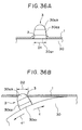
Next, as shown in Fig. 36, each of the sprocket pins 30a
has a cylindrical surface 30a1 formed at its base portion, a
tapered surface 30a2 formed above the cylindrical surface
30a, and an R surface 30a3 formed atop the cylindrical
surface 30a2. The sprocket holes 3 are press fitted over the
cylindrical surfaces 30a1 of the sprocket pins 30a.
As shown in Figs. 34 and 35, the width through which the
sprocket holes 3 along the side of the printing sheet 1
corresponding to the sprockets 30a disposed along a reference
position P5 at one end of the cylinder 30 are press fitted
over those sprockets 30a is made large, and the width through
which the sprocket holes 3 along the other side of the
printing sheet 1 corresponding to the sprockets 30a disposed
along a non-reference position P6 at the other end of the
cylinder 30 is made small.
That is, the tolerance of the diameter D1 of the
cylindrical surface 30a1 shown in Fig. 36 at the base of each
sprocket pin 30a is set at upper limit = 0mm, lower limit =
0.009mm with respect to 4mm for all the sprocket pins 30a of
the two rows, but the tolerance of the diameter D2 of the two
rows of sprocket holes 3 is set at upper limit = 0.03mm,
lower limit = 0.07mm with respect to 4mm on the reference
position P5 side and is set at upper limit = 0mm, lower limit
= 0.02mm with respect to 4mm on the non-reference position P6
side.
As shown in Figs. 30 to 33, the jacket loading table 28
is disposed on a horizontal tangent of the top of the
periphery of the cylinder 30, and the vertical position line
connecting the axis of rotation of the cylinder 30 and the
intersection of this tangent and the top of the cylinder 30
is set to be the press fitting position P11 of the sprocket
holes 3 with respect to the sprocket pins 30a. A position
approximately 15° behind this press fitting position P11 in
the arrow c' direction is set to be a reference position P12
of the circumferential direction of the cylinder 30, and a
position about 30° in front of the press fitting position P11
in the arrow c' direction is set to be a printing sheet
clamping position P13.
Used in the printing sheet winding device 251 are a
left/right pair of printing sheet pressing plates 256 which
serve as both printing sheet lifting-off means and printing
sheet pressing means, a left/right pair of printing sheet
press fitting rollers 257 constituting printing sheet press
fitting means, a printing sheet clamper 258, a left/right
pair of locking pins 259 which constitute clamper control
means, a magnet 260 for attracting the printing sheet clamper
258, and a printing sheet guide 261.
Next, with reference to Figs. 40 to 45, the drive device
264 of the printing sheet pressing plates 256 will be
described.
First, as shown in Fig. 40, the left/right pair of
printing sheet pressing plates 256 are disposed left/right
symmetrically at the inner sides of the left/right pair of
cylinder support frames 253 in positions at the reference
position P12 over the two rows of sprocket pins 30a of the
cylinder 30. A left/right pair of printing sheet pressing
plate drive devices 264 which drive this left/right pair of
printing sheet pressing plates 256 are mounted left/right
symmetrically on the outer sides of the left/right pair of
cylinder support frames 253.
The printing sheet pressing plates 256 are made of
plastic and each have an elastic twin-pronged arm 256a and a
slot 256b open in the arrow (a) direction formed in their
central portion. Base portions of the printing sheet
pressing plates 256 pass through long holes 265 formed
diagonally in the cylinder support frames 253 and project to
the outer sides of the cylinder support frames 253 and are
fixed to support plates 266 disposed on the outer sides of
the cylinder support frames 253.
The support plates 266 are each guided by a total of
four guide rollers 267 mounted on the outer side of the
respective cylinder support frame 253 so that the printing
sheet pressing plates 256 move in the direction of the arrows
c, c', which is diagonally up and down with respect to the
position P12.
The printing sheet pressing plate drive devices 264 each
comprise a worm 270 linked by a coupling 269 to a drive motor
268 mounted on a bracket 268a, a worm wheel 271 meshing with
the worm 270, a pinion 273 linked via an intermediate gear
272 to the worm wheel 271, a rack 274 fixed to the supporting
plate 266 and meshing with the pinion 273, a shutter plate
275 fixed to the side surface of the rack 274, and a pair of
sensors S9, S10, comprising photocouplers, which are switched
ON and OFF by the shutter plate 275.
When the drive motor 268 is forward rotationally driven,
the printing sheet pressing plates 256 are moved integrally
with the supporting plates 266 by the drive motor 268 via the
worms 270, the worm wheels 271, the intermediate gears, the
pinions 273 and the racks 274 to the operating positions
shown by solid lines in Figs. 30 and 44; the sensors S9
detect the movement of the shutter plate 275, and the drive
motor 268 is automatically stopped.
When the drive motor 268 is reverse rotationally driven,
in the reverse of the above, the printing sheet pressing
plates 256 are moved to the non-operating positions shown by
broken lines in Figs. 30 and 44; the other sensors S10 detect
the movement of the shutter plate 275, and the drive motor 68
is automatically stopped.
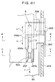
Next, with reference to Figs. 40, 42, and 46 to 48, the
drive devices 278 of the printing sheet press fitting rollers
257 will be described.
First, the left/right pair of printing sheet press
fitting rollers 257 are made of plastic, and each has a
central circular groove 257a formed around the central
portion of its periphery. These left/right pair of printing
sheet press fitting rollers 257 are disposed left/right
symmetrically inside the left/right pair of cylinder support
frames 253 in positions at the press fitting position P11 over
the two rows of sprocket pins 30a of the cylinder 30. The
left/right pair of printing sheet press fitting roller drive
devices 278 which drive these left/right pair of printing
sheet press fitting rollers 257 are mounted left/right
symmetrically on the inner sides of the left/right pair of
cylinder support frames 253.
Each printing sheet press fitting roller drive device
278 comprises a supporting shaft 279 horizontally mounted on
the respective cylinder support frame 253; a supporting arm
280 rotatably mounted on the supporting shaft 279 and having
the printing sheet press fitting roller 257 rotatably mounted
on its end; a drive arm 281 pivotally mounted on the same
supporting shaft 279; a limiter spring 282, consisting of a
tension spring, fitted between the supporting arm 280 and the
drive arm 281; a plunger solenoid 283, which is means for
driving the drive cam 281 by means of a plunger 283a, mounted
on the cylinder support frame 253; a stopper 285 of the drive
arm 281; a return spring 284 of the plunger 283a, consisting
of a tension spring; and a microswitch S11 turned ON and OFF
by the drive arm 281. The plunger 283a and the drive arm 281
are linked by a pin 283a, and the stopper 285 is formed
integrally with the bracket 283c of the plunger solenoid 283.
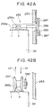
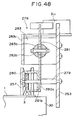
When the plunger solenoid 283 is OFF, as shown by broken
lines in Fig. 47, the drive arm 281 is pivoted by the return
spring 284 in the arrow c2' direction and abuts with the
stopper 285, and mutually abutting parts 281a and 280a formed
between the drive arm 281 and the support arm 280 cause the
support arm 280 to rotate in the arrow c3' direction and the
printing sheet press fitting roller 257 is lifted as far as
the press fitting release position shown by broken lines in
Figs. 30 and 37 and the microswitch S11 is switched OFF.
When the plunger solenoid 283 is switched ON, as shown
by solid lines in Fig. 47, the drive arm 281 is rotated in
the arrow c2 direction by the plunger 283a against the
resistance of the return spring 284 and the support arm 280
is pivoted in the arrow c3 direction by the limiter spring
282. The printing sheet press fitting roller 257 is lowered
in the arrow c3 direction to the press fitting position shown
by solid lines in Figs. 30 and 47, is pushed in the arrow c3
direction against the periphery of the cylinder by the
elastic force of the limiter spring 282, and the microswitch
S11 is switched ON by the drive arm 281.
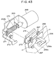
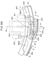
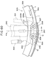
Referring now to Figs. 30 to 33 and 49 to 62, the
support mechanism 288 of the printing sheet clamper 258 will
be described.
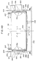
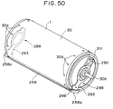
As shown in Figs. 49 to 51, the printing sheet clamper
258 is a belt-shaped plate made of a strongly magnetic
material such as steel plate, and the overall length of this
printing sheet clamper 258 is slightly greater than the
overall length of the cylinder. Also, this printing sheet
clamper 258 is curved in a circular arc along the periphery
of the cylinder in a direction normal to its length
direction. This printing sheet clamper 258 is pressed
against and separated from the periphery of the cylinder
while being held parallel with the axis of the cylinder by a
left/right pair of printing sheet clamper support mechanisms
288.
As shown in Figs. 30 to 33 and 50 to 62, the left/right
pair of printing sheet clamper support mechanisms 288 are
left/right symmetrically mounted on the ends of the cylinder.
The printing sheet clamper support mechanisms 288 each
comprise a rotary support table 290 rotatably mounted via a
bearing 289 on the left/right ends of the shaft 30b of the
cylinder and a clamper support plate 293 mounted on the side
of the rotary support table 290 slidably with respect to the
rotary support table 290 in the direction of the arrows c4,
c4', which is a direction orthogonal to the axial direction
of the cylinder, via a pair of screws/guide pins 291 and a
pair of long holes 292.
A left/right pair of bent pieces 258a are each bent into
a right angle toward the center of the cylinder at the ends
of the printing sheet clamper 258. A left/right pair of
support pin mating holes 294 are formed in the ends of the
left/right pair of bent pieces 258a in positions biased to
one side in the circumferential direction of the cylinder
from the center P14 of the printing sheet clamper 258 in the
circumferential direction of the cylinder. A left/right pair
of support pin mating holes 295 formed in positions slightly
biased in one direction from the above-mentioned center P14
in the ends of the left/right symmetrical left/right pair of
clamper support plates 293 and the left/right pair of support
pin mating holes 294 in the printing sheet clamper 258 are
pivotally linked to each other by a left/right pair of
support pins 296.
As a result, the ends of the printing sheet clamper 258
are supported by the left/right pair of clamper support
plates 293 and this printing sheet clamper 258 is movable in
the direction of the arrows c4, c4', which is a direction
orthogonal to the axial direction of the cylinder, while
being held parallel to the cylinder, and this printing sheet
clamper 258 can pivot with respect to the left/right pair of
clamper support plates 293 about the left/right pair of
support pins 296 in the direction of the arrows c5, c5' shown
in Figs. 57 and 58.
A left/right pair of spring attachment plates 297 are
left/right symmetrically fixed by fixing screws 298 to the
side surfaces of the left/right pair of rotary support plates
290 in positions peripheral to the bearings 289 so as to lie
across the left/right pair of clamper support plates 293.
Left/right pairs of pressure springs 301 and 302, consisting
of tension springs, four springs in total, are fitted between
spring anchorages 299a and 299b formed on the left/right pair
of spring attachment plates 297 and spring anchorages 300a
and 300b formed respectively on the opposite end portions of
the bent pieces 258 from the support pin mating holes 294 and
side portions of the left/right pair of clamper support
plates 293.
As a result, the printing sheet clamper 258 is pivotally
urged in the arrow c5 direction with respect to the
left/right pair of clamper support plates 293 about the
left/right pair of support pins 296 by the left/right pair of
pressure springs 301, and the printing sheet clamper 258 and
the left/right pair of clamper support plates 293 are
together strongly urged in the direction c4 with respect to
the left/right pair of rotary support plates 290 by the
left/right pairs, four springs in total, of pressure springs
301 and 302.
Next, with reference to Figs. 30 to 33, 50, 51, and 53
to 60, a cam mechanism 305 constituting part of a clamper
control mechanism for effecting clamping and unclamping of
the printing sheet clamper 258 will be described.
This cam mechanism 305 is made up of a left/right pair
of concentric circular cams 306 fixed with screws to the ends
of the cylinder around the vicinity of the periphery thereof,
and left/right pairs of cam follower rollers 307, 308,
consisting of bearings, rotatably mounted on the inner sides
of the left/right pair of bent pieces 258 of the printing
sheet clamper 258 in positions on opposite sides of the
center P14 in the circumferential direction of the cylinder.
The left/right pairs of cam follower rollers 307 and 308
are pressed in the arrow c4 direction against circular
peripheral surfaces 306a, concentric with the cylinder, of
the left/right pair of cams 306 by the left/right pairs of
springs 301 and 302. A left/right pair of concave portions
306b into which the left/right pairs of cam follower rollers
307, 308 can descend simultaneously are formed in parts of
the peripheral surfaces 306a of the left/right pair of cams
306.
Next, with reference to Figs. 30 to 33 and 52 to 56, a
fixed position lock mechanism 311, constituting another part
of the printing sheet clamper control mechanism, for locking
and unlocking the left/right pair of printing sheet clamper
support mechanisms 288 in the printing sheet clamping
position P13 shown in Figs. 30 to 33, will be described.
This fixed position lock mechanism 311 is made up of a
left/right pair of slots 312 formed in the opposite ends of
the left/right pair of rotary support plates 290 from the
printing sheet clamper 258 and a left/right pair of locking
pins 259 free to enter and exit this left/right pair of slots
312 in the direction of the arrows c6, c6', parallel to the
axis of the cylinder.
Next, with reference to Figs. 63 to 66, a left/right
pair of lock pin drive mechanisms 315, which drive the
locking pins 259 in the direction of the arrows c6, c6', will
be described.
These lock pin drive mechanisms 315 are mounted
left/right symmetrically on the printing sheet clamping
position P13 on the outer sides of the left/right pair of
cylinder support frames 253. Each lock pin drive mechanism
315 is made up of a locking pin guide 317 which guides the
respective locking pin 259 in and out through a through hole
316 formed in the respective cylinder support frame 253 in
the direction of the arrows c6, c6'; a feed screw 318 disposed
coaxially with the lock pin 259 at the opposite end of the
lock pin 259 from the cylinder; a drive motor 320, mounted on
a bracket 319, which moves the feed screw 318 in the
direction of the arrows c6, c6'; a return spring 321,
consisting of a compression spring, which at all times pushes
the lock pin 259 against the end of the feed screw 318 in the
arrow c6' direction; a shutter plate 323, fitted on the feed
screw 318 side end portion of the lock pin 259 and guided by
a guide shaft 322 parallel to the lock pin 259, which moves
in the direction of the arrows c6, c6' integrally with the
lock pin 259; and a pair of sensors S12, S13, which consist of
photocouplers and are ON/OFF actuated by the shutter plate
323.
When the drive motor 320 is driven to rotate forward, as
shown by solid lines in Figs. 64 and 65, the feed screw 318
is moved in the arrow c6 direction against the resistance of
the return spring 321, and the end of this lock pin 259 is
inserted into the slot 312 in the rotary support plate 290.
This lock pin 259 thereby locks the rotary support plate 290
in the printing sheet clamping position P13. The sensor S12
detects the movement of the shutter plate 323, and the
locking of the rotary support plate 290 is thereby confirmed.
When the drive motor 320 is driven in reverse, as shown
by broken lines in Figs. 64 and 65, the feed screw 318 is
moved in the arrow c6' direction by the return spring 321,
the lock pin 259 exits the slot 312 in the rotary support
plate 290 and the rotary support plate 290 is unlocked from
the printing sheet clamping position P13. The other sensor
S13 detects the movement of the shutter plate 323, and the
unlocking of the rotary support plate 290 is thereby
confirmed.
As shown in Figs. 49 and 59 to 62, a magnet 260 is
recessed in the periphery of the cylinder in a roughly
central position P15 in the axial direction of the cylinder,
whereby the roughly central portion in the length direction
of the printing sheet clamper 258 pressed against the
periphery of the cylinder in the printing sheet clamping
position P13 is pulled against the periphery of the cylinder
by magnetic attraction.
As shown in Figs. 30 to 33, the printing sheet guide 261
is mounted on the chassis 252 in parallel with the cylinder
and is below the arrow c' direction side vicinity of the
printing sheet clamper 258 when the printing sheet clamper
258 is in position in the printing sheet clamping position
P13.
Before the start of printing sheet winding device
operation, first, as shown in Fig. 85, the left/right pairs
of cam follower rollers 307, 308 of the left/right pair of
cam mechanisms 305 are down in the concave portions 306b of
the left/right pair of cams 306, and the printing sheet
clamper 258 is being pressed by the left/right pair of
pressure springs 301, 302 in the direction of the arrow c4
against the periphery of the cylinder. Therefore, in this
state, when the cylinder is driven to rotate, the printing
sheet clamper support mechanisms 288 rotate integrally with
the cylinder.
Next, a printing sheet jacket 6 is loaded onto the
jacket loading table 28 of the printing sheet feed and eject
device 29 shown in Figs. 10 to 12, and when the sensor S2
detects the printing sheet jacket 6 the automatic winding of
the printing sheet 1 onto the periphery of the cylinder
begins.
That is, first, as shown in Fig. 30, the cylinder is
driven in the direction of the arrow c by the cylinder drive
mechanism 229, and, based on detection of the position of the
cylinder by the rotary encoder 232, the left/right pair of
printing sheet clamper support mechanisms 288 are stopped in
the printing sheet clamping position P13.
Then, the left/right pair of lock pins 259 are driven in
the direction of the arrow c6 by the left/right pair of lock
pin drive mechanisms 315 shown in Figs. 63 to 66, and, as
shown in Figs. 55 and 56, the left/right pair of lock pins
259 are inserted in the arrow c6 direction into the
left/right pair of slots 312 in the left/right pair of rotary
support plates 290.
When this happens, as shown in Fig. 30, the left/right
pair of printing sheet clamper support mechanisms 288 and the
printing sheet clamper 258 are brought into position in the
printing sheet clamping position P13 integrally with the
left/right pair of rotary support plates 290.
When the sensor S12 of the lock pin drive mechanism 315
confirms the above locked state, the cylinder is rotated
further in the arrow c direction.
Then, as shown in Fig.59, the left/right pairs of cam
follower rollers 307, 308 of the left/right pair of cam
mechanisms 305 are pushed up from the concave portions 306b
of the left/right pair of cams 306 onto the outer peripheral
surfaces 306a, and, as shown in Figs. 30 and 59 with broken
lines, the printing sheet clamper 258 is separated from the
periphery of the cylinder in the arrow c4' direction against
the resistance of the left/right pairs of pressure springs
301, 302 while remaining parallel to the cylinder, and the
printing sheet clamper 258 is thereby unclamped.
The cylinder continues to rotate in the direction of the
arrow c, and first pins 30A, which are a left/right pair of
reference pins among the two rows of sprocket pins 30a on the
periphery of the cylinder 30, are brought into the reference
position P12, as shown in Fig. 37 with broken lines, and the
cylinder is stopped.
After this, the automatic pulling in of the printing
sheet jacket 6 in the direction of the arrow (a) to the
above-mentioned fixed position and the automatic pulling out
of the printing sheet 1 in the direction of the arrow (a)
from inside the printing sheet jacket 6 are started by the
printing sheet feed and eject device 29, shown in Figs. 10 to
12, and, as shown in Figs. 30 and 37, the leading end of the
printing sheet 1 is fed roughly tangentially to the cylinder
in the direction of the arrow (a) to the press fitting
position P11 of the cylinder.
At this time, the sensor S6 of the printing sheet feed
and eject device 29 counts the sprocket holes 3 of the
printing sheet 1 being fed in the direction of the arrow (a)
and thereby detects the extent to which the printing sheet 1
has been pulled out in the direction of the arrow (a).
When the sensor S6 detects that the printing sheet 1 has
been pulled out as far as the above-mentioned fixed position,
the left/right pair of first pins 30A of the cylinder start
to move from the reference position P12 toward the press
fitting position P11.
At the same time, the left/right pair of printing sheet
pressing plate drive devices 264 and the left/right pair of
printing sheet press fitting roller drive devices 278 shown
in Figs. 43 to 45 and 46 to 48 lower the left/right pair of
printing sheet pressing plates 256 and the left/right pair of
printing sheet press fitting rollers 257 respectively from
the non-operating positions and non-pressing positions shown
with broken lines in Fig. 37 into the operating positions and
pressing positions shown with solid lines in Fig. 37 in the
direction of the arrow c1 and the direction of the arrow c3.
At this time, as shown in Figs. 37, 41 and 42(A), the
twin-pronged arms 256a of the left/right pair of printing
sheet pressing plates 256, having the slots 256b in their
central portions, press the leading end of the printing sheet
1 down elastically in the direction of the arrow c1 onto the
periphery of the cylinder 30 on both sides of each of the
left/right pair of first pins 30A.
By this action, as shown in Figs. 34 and 35, the
left/right pair of first pins 30A of the cylinder are firmly
engaged with the first holes 3A at the leading ends of the
two rows of sprocket holes 3 in the printing sheet 1.
Also, at this time, as shown in Figs. 37, 41 and 42(B),
the left/right pair of printing sheet press fitting rollers
257, having the circular grooves 257a around their central
portions, elastically press the leading end of the printing
sheet 1 in the direction of the arrow c3 onto the periphery
of the cylinder 30 on both sides of the locuses of movement
of the two rows of sprocket pins 30a on the cylinder.
When low speed rotation of the cylinder in the direction
of the arrow c has brought the left/right pair of first pins
30A of the cylinder to the press fitting position P11, as
shown in Figs. 35(B), 38 and 41, the left/right pair of
printing sheet press fitting rollers 257 press the printing
sheet 1 in the direction of the arrow c3 on the left and
right sides of the left/right pair of first pins 30A, and the
left/right pair of first sprocket pins 3A are firmly press
fitted onto the left/right pair of first pins 30A down to the
cylindrical surfaces 30a1, shown in Fig. 36(A), at the bases
of the first pins 30A.
A fixed period of time after the left/right pair of
printing sheet press fitting rollers 257 are lowered in the
direction of the arrow c to the press fitting positions shown
by solid lines in Fig. 38, the left/right pair of printing
sheet pressing plates 256 are raised in the arrow c1'
direction to their non-operating positions.
Then, as shown in Fig. 31, the cylinder continues to
rotate at low speed, and by being pulled in the direction of
the arrow c by the left/right pair of first pins 30A the
printing sheet 1 is automatically pulled out of the printing
sheet jacket 6, the sprocket pins 30a disposed in two rows on
the cylinder are inserted two by two into the sprocket holes
3 formed in two rows in the printing sheet 1, the two rows of
sprocket holes 3 are firmly press fitted by the left/right
pair of printing sheet press fitting rollers 257 onto the two
rows of sprocket pins 30a down to the cylindrical surfaces
30a1 at the bases thereof shown in Fig. 36(A), and the
printing sheet 1 is thereby automatically wound onto the
periphery of the cylinder 30.
At this time, the end 1b of the printing sheet 1 is
guided by the printing sheet guide 261 so that it smoothly
passes through the gap between the printing sheet clamper 258
and the periphery of the cylinder 30.
Then, as shown in Fig. 31, when the cylinder has rotated
through 375° from the reference position P12, the printing
sheet 1 is wound around the periphery of the cylinder 30
through 360° + α, and the trailing end 1c of the printing
sheet 1 overlaps the leading end of the printing sheet 1.
When the cylinder has rotated through 405° from the
press fitting position P11, as shown in Figs. 55, 56, 60 and
62, the left/right pairs of cam follower rollers 307, 308
descend from the outer peripheral surfaces 306a of the
left/right pair of cams 306 into the concave portions 306b,
the printing sheet clamper 258 is strongly pressed in the
direction of the arrow c4 onto the periphery of the cylinder
30 by the left/right pairs of pressure springs 301 and 302,
four springs in total, as shown with solid lines in Fig. 49,
and, as shown in Fig. 62, the printing sheet clamper 258
strongly presses the trailing end 1c of the printing sheet 1
onto the leading end 1b and onto the periphery of the
cylinder 30 in the direction of the arrow c4, and the leading
end 1b and the trailing end 1c of the printing sheet 1 are
thereby simultaneously clamped strongly onto the periphery of
the cylinder 30.
At this time, while the cylinder is rotating in the
direction of the arrow c, after the left/right pairs of cam
follower rollers 307, 308 have descended into the concave
portions 306b of the cams 306 once and the printing sheet
clamper 258 has been pressed against the periphery of the
cylinder 30 in the direction of the arrow c4, the left/right
pair of cam follower rollers 307, 308 are pushed up again by
the outer peripheral surfaces 306a of the cams 306 and the
printing sheet clamper 258 is separated in the direction of
the arrow c4' from the periphery of the cylinder 30.
However, the positions of the concave portions 306b of the
cams 306 are set so that this action occurs before the
leading end of the printing sheet 1 wound in the direction of
the arrow c on the periphery of the cylinder 30 reaches the
printing sheet clamper 258.
When the printing sheet clamper 258 has simultaneously
clamped the leading end 1b and the trailing end 1c of the
printing sheet 1, as shown in Figs. 49 and 62, the magnet 260
recessed in the periphery of the cylinder 30 attracts and
strongly holds the roughly central portion, in the length
direction, of the printing sheet clamper 258.
After the clamping of the leading end 1b and the
trailing end 1c of the printing sheet 1 by the printing sheet
clamper 258 is confirmed by the rotary encoder 232 and the
cylinder is stopped, as shown in Fig. 32 the left/right pair
of printing sheet press fitting rollers 257 are raised in the
direction of the arrow c3' to their non-operating positions
and, as shown in Fig. 56 by broken lines, the left/right pair
of lock pins 259 are withdrawn in the direction of the arrow
c5' from the left/right pair of slots 312 in the left/right
pair of rotary support plates 290 and the rotary support
plates 290 are thereby unlocked from their fixed positions.
After that, the engraving step described hereinbefore is
begun: the cylinder is rotated at high speed in the direction
of the arrow c, and engraving of image data 2 of a photograph
or the like onto the surface 1a of the printing sheet 1 is
carried out.
During this engraving step the printing sheet clamper
258 is rotated at high speed integrally with the cylinder
while still clamping the printing sheet 1, and a phenomenon
occurs wherein centrifugal force created by the high speed
rotation causes the roughly central portion in the length
direction of the printing sheet clamper 258 to float up from
the periphery of the cylinder 30 in the direction of the
arrow c4' into a circular arc shape and the clamping force on
the printing sheet 1 decreases.
However, because the magnet 260 recessed in the
periphery of the cylinder 30 strongly attracts the roughly
central portion in the length direction of the printing sheet
clamper 258, this phenomenon is prevented from being a
problem.
When the printing sheet 1 is to be unwound from the
periphery of the cylinder 30, as shown in Fig. 32, after the
left/right pair of rotary support plates 290 are unlocked
from the printing sheet clamping position by the left/right
pair of lock pins 259, the cylinder is rotated through a
predetermined angle in the direction of the arrow c and, as
shown in Fig. 59, the left/right pairs of cam follower
rollers 307, 308 are pushed from the concave portions 306b of
the left/right pair of cams 306 up onto the outer peripheral
surfaces 306a, and the printing sheet clamper 258 is thereby
unclamped in the direction of the arrow c4'.
Next, as shown in Figs. 33 and 39, the left/right pair
of printing sheet pressing plates 256 are lowered in the
direction of the arrow c1 to their operating positions, and
these printing sheet pressing plates 256 push the printing
sheet 1 elastically onto the periphery of the cylinder 30
from above.
After that, the cylinder is rotated reversely in the
direction of the arrow c' and the printing sheet 1 is
automatically unwound from the cylinder starting from its
trailing end 1c by the left/right pair of printing sheet
pressing plates 256. At this time, the printing sheet 1 is
lifted up from the bases of the sprocket pins 30a on the
cylinder by the twin-pronged arms 256a of the left/right pair
of printing sheet pressing plates 256, and the sprocket holes
3 of the printing sheet 1 are sequentially automatically
wound off the two rows of sprocket pins 30a on the cylinder.
The printing sheet 1 is guided by the left/right pair of
printing sheet pressing plates 256 and automatically inserted
in the direction of the arrow a' into the printing sheet
jacket 6 on the jacket loading table 28.
As shown in Fig. 59, when while the printing sheet
clamper 258 is unclamped the cam follower rollers 307, 308
are pushed up in the direction of the arrow c4' from the
concave portions 306b of the cams 306 rotating in the
direction of the arrow c, first the printing sheet clamper
258 is pivoted in the direction of the arrow c5' about the
support pins 296, as shown in Fig. 59 with broken lines, and
then the printing sheet clamper 258 is pivoted in the
direction of the arrow c5 about the pair of cam follower
rollers 307, as shown in Fig. 59 with solid lines.
Consequently, while the printing sheet clamper 258 is
unclamped, the ends of the printing sheet clamper 258 in the
circumferential direction of the cylinder are alternately
pulled away from the periphery of the cylinder 30 in the
direction of the arrow c5' and the direction of the arrow c5,
and a pivoting movement of the printing sheet clamper 258 in
the direction of the arrow c5 and the direction of the arrow
c5' occurs.
Because the levering action of this printing movement of
the printing sheet clamper 258 in the direction of the arrow
c5 and the direction of the arrow c5' enables the printing
sheet clamper 258 to readily separate from the magnet 260,
unclamping of the printing sheet clamper 258 can be effected
easily.
At the start of winding of the printing sheet 1 onto the
periphery of the cylinder 30, as shown in Fig. 37, the
left/right sides of the leading end 1b of the printing sheet
1 are pushed elastically against the periphery of the
cylinder 30 by the left/right pair of printing sheet pressing
plates 256 and the first pins 30A of the two rows of sprocket
pins 30a are reliably inserted into the first sprocket pins
3A of the two rows of sprocket holes 3; during the winding
operation, as shown in Figs. 38 and 36(A), because the two
rows of sprocket holes 3 are sequentially press fitted
securely onto the two rows of sprocket pins 30a by the
left/right pair of printing sheet press fitting rollers 257,
the automatic winding of the printing sheet 1 onto the
periphery of the cylinder 30 can be performed correctly and
smoothly.
Next, during automatic winding of the printing sheet 1
onto the periphery of the cylinder 30, because the first pins
30A of the two rows of sprocket pins 30a can be always
reliably inserted into the first sprocket pins 3A of the two
rows of sprocket holes 3, as shown in Figs. 30 and 35,
positioning of the printing sheet 1 with respect to the
reference position P12 in the circumferential direction of the
cylinder can be performed with high accuracy.
Because as shown in Fig. 34 the pitch P1 and the span P2
of the two rows of sprocket pins 30a on the periphery of the
cylinder 30 are approximately 0.01 to 0.03mm larger than the
engaging pitch P3 and the engaging span P4 of the two rows of
sprocket holes 3 in the printing sheet 1, when the two rows
of sprocket holes 3 in the printing sheet 1 are press fitted
onto the two rows of sprocket pins 30a on the cylinder and
the printing sheet 1 is wound on the periphery of the
cylinder 30, as shown in Fig. 35, between the two rows of
sprocket pins 30a in the axial direction of the cylinder and
between adjacent sprocket pins 30a in the circumferential
direction of the cylinder it is possible to produce a tension
in the printing sheet 1 in the X direction, which is the
cylinder axial direction, and in the Y direction, which is
the cylinder circumferential direction.
Furthermore, at this time, because as shown in Figs. 34
and 35 the width through which the sprocket holes 3 on the
side of the printing sheet 1 corresponding to the sprocket
pins 30a along the reference position P5 at one end of the
cylinder are press fitted onto those sprocket pins 30a is
large and the width through which the sprocket holes 3 on the
other side of the printing sheet 1 corresponding to the
sprocket pins 30a along the non-reference position P6 at the
other end of the cylinder are press fitted onto those
sprocket pins 30a is small, as shown in Fig. 35 by the arrow
X direction, the whole printing sheet 1 is pulled toward the
reference position P5 side and the printing sheet 1 is
positioned with high accuracy with respect to the reference
position P5.
Consequently, the printing sheet 1 automatically wound
onto the periphery of the cylinder 30 can be positioned with
high accuracy in both the circumferential direction of the
cylinder referenced by the reference position P12 and the
axial direction of the cylinder referenced by the reference
position P12.
Furthermore, because the printing sheet 1 automatically
wound onto the periphery of the cylinder 30 is given tensions
between the sprocket pins 30a in the X and Y directions that
are the axial and circumferential directions of the cylinder,
absolutely no slippage or wrinkling of the printing sheet 1
occurs.
Because as shown in Fig. 36(A) each sprocket pin 3a is
formed with a cylindrical surface 30a1 at the base, a taper
surface 30a2 above that and an R surface 30a3 above that, as
shown in Fig. 36(A) the press fitted sprocket holes 3 of the
printing sheet 1 can be positioned stably and with high
accuracy and yet as shown in Fig. 36(B) during the insertion
and withdrawal of the sprocket pins 30a with respect to the
sprocket holes 3 in the printing sheet 1 which accompanies
the rotation of the cylinder in the direction of the arrows
c, c' the guiding action of the R surface 30a3 and the taper
surface 30a2 of each sprocket pin 30a enables the sprocket
pins 30a to enter and exit the sprocket holes 3 unforcedly
and smoothly.
The printing sheet feed and eject device of the printing
sheet making and printing system of the present invention
described above provides the following kinds of benefits:
Just by loading a printing sheet jacket onto a jacket
loading table, the complete automation of the feeding and
ejection of a printing sheet to and from a cylinder can be
achieved, and an operator can carry out feeding and ejection
of a printing sheet with respect to a cylinder extremely
easily and without directly touching the printing sheet.
Therefore, the adhesion of dust and the occurrence of
scratching on the surface of the printing sheet can be
completely avoided and stable printed matter with no color
blurring or scumming can be obtained. Also, because a
printing sheet ejected from the cylinder of a printing
machine has ink on it, if an operator were to touch the
printing sheet directly the operator would get ink on his
hands, but the present apparatus eliminates such problems and
is extremely sanitary.
Because it is possible to completely automate the
feeding and ejection of a printing sheet to and from a
cylinder, the invention facilitates development toward a
completely automatic electronic gravure printing system which
can be run unmanned.
Because there are provided a number of sensors which
detect the position of the printing sheet jacket loaded on
the jacket loading table and activate the jacket pulling in
means and detect that the printing sheet jacket has been
pulled in as far as a fixed position and sequentially
activate the flap opening means and the printing sheet
pulling out means, the chain of operations following the
loading of the printing sheet jacket onto the jacket loading
table, consisting of the automatic pulling in of the printing
sheet jacket, the automatic opening of the printing sheet
jacket and the automatic pulling out of the printing sheet
from inside the printing sheet jacket, can be systematically
carried out in correct sequence.
Because the jacket pulling in means is provided with a
left/right pair of roller press portions formed at the left
and right sides of the printing sheet jacket and a left/right
pair of drive rollers which are pressed onto these roller
press portions, by forward and reverse rotation of the
left/right pair of drive rollers pressed onto the left/right
pair of roller press portions the automatic pulling in and
automatic ejection of the printing sheet jacket on the jacket
loading table can be carried out accurately and easily.
Because the flap opening means is provided with suction-gripping
means for suction-gripping and opening the printing
sheet removal/insertion opening end of the printing sheet
jacket, the printing sheet removal/insertion opening end of
the printing sheet jacket can be suction-gripped and
accurately and easily opened by this suction-gripping means.
Because the printing sheet pulling out means is provided
with sprocket holes spaced at a fixed pitch along the left
and right sides of the printing sheet and a left/right pair
of sprockets which are engaged with the sprocket holes
through a left/right pair of sprocket access holes formed in
the printing sheet jacket, by forward and reverse rotation of
the left/right pair of sprockets engaged with the sprocket
holes in the left and right sides of the printing sheet
through the left/right pair of sprocket access holes in the
printing sheet jacket automatic pulling out of the printing
sheet from the printing sheet jacket and automatic
reinsertion of the printing sheet into the printing sheet
jacket can be carried out accurately and easily.
Because the printing sheet is pulled out of the printing
sheet jacket and fed to the cylinder by the left/right pair
of sprockets engaged with the two rows of sprocket holes
formed along the left and right sides of the printing sheet,
and the thus fed printing sheet is wound onto the periphery
of the cylinder by the two rows of sprocket pins disposed
around the ends of the cylinder being inserted into the two
rows of sprocket holes in the printing sheet, the structure
is simple and the operation is reliable, and the operations
of winding and unwinding the printing sheet onto and off the
cylinder can be carried out stably.
Because after the two rows of sprocket pins on the
cylinder have entered the two rows of sprocket holes in the
printing sheet and the printing sheet is thereby wound onto
the periphery of the cylinder at least the trailing end of
the wound printing sheet is clamped by a printing sheet
clamper onto the periphery of the cylinder, slippage and
wrinkling of the printing sheet wound on the cylinder do not
readily occur. Consequently the interchangeability of the
printing sheet with respect to the cylinder is good, and when
image data such as a photograph is engraved color by color in
colors such as cyan, magenta, yellow and black and multicolor
overprinting is carried out, color non-alignment, color
blurring, image distortion and scumming and the like do not
readily occur and high image quality, fine gravure printing
can be performed.
Because there are provided detecting means for detecting
the extent to which the printing sheet has been pulled out of
the printing sheet jacket by counting the sprocket holes in
the printing sheet and cylinder rotational drive means and
cylinder position detecting means for setting the sprocket
pins of the sprocket printing sheet on the cylinder to a
reference position and based on a signal from the detecting
means rotating the cylinder and thereby inserting the
sprocket pins into the first sprocket holes of the sprocket
holes and on completion of the winding of the printing sheet
which accompanies the rotation of the cylinder through a
predetermined angle stopping the cylinder in a printing sheet
clamping position, the chain of operations comprising the
automatic winding and clamping of the printing sheet onto the
cylinder can at all times by performed accurately and
reliably.
Because there is provided another detecting means for
detecting the loading of the printing sheet jacket as far as
a fixed position on the jacket loading table and sequentially
forwardly rotating the left/right pair of sprockets and the
cylinder, just by loading the printing sheet jacket onto the
jacket loading table the printing sheet can be automatically
pulled out from inside the printing sheet jacket and
automatically wound onto the periphery of the cylinder, and
the operatability is further improved.
By forward rotation of the cylinder the two rows of
sprocket pins at the ends of the periphery of the cylinder
are made to enter the two rows of sprocket holes formed in
the printing sheet inside the printing sheet jacket two by
two and the printing sheet is thereby automatically pulled
out of the printing sheet jacket and wound onto the periphery
of the cylinder. During this printing sheet winding
operation the two rows of sprocket holes are press fitted
onto the two rows of sprocket pins as far as the base
portions thereof; at this time, because the pitch in the
circumferential direction of the cylinder and the span in the
axial direction of the cylinder of the two rows of sprocket
pins are made slightly greater than the engaging pitch and
the engaging span of the two rows of sprocket holes with
respect to the sprocket pins, positioning of the printing
sheet on the cylinder can be performed with high accuracy so
that no slippage or wrinkling of the printing sheet occurs
whatsoever. As a result the interchangeability of the
printing sheet with respect to the cylinder is extremely
good, and when image data such as a photograph is engraved
color by color in colors such as cyan, magenta, yellow and
black and multicolor overprinting is carried out, color non-alignment,
color blurring, image distortion and scumming and
the like do not readily occur and high image quality, fine
gravure printing can be performed.
Because the width through which the sprocket holes along
the side of the printing sheet corresponding to the sprocket
pins disposed along an axial reference position at one end of
the cylinder are press fitted onto those sprocket pins is
made large and the width through which the sprocket holes on
the other side of the printing sheet corresponding to the
sprocket pins disposed along a non-reference position at the
other end of the cylinder are press fitted onto those
sprocket pins is made small, the printing sheet wound on the
cylinder can be positioned with high accuracy with respect to
the axial direction reference position on the cylinder and
the interchangeability of the printing sheet with respect to
the cylinder is further raised.
Because each of the sprocket pins on the cylinder has a
cylindrical surface formed at its base, a tapered surface
formed above that and an R surface formed atop the tapered
surface, notwithstanding that the printing sheet can be
positioned with high accuracy with respect to the cylinder,
the insertion and removal of the sprocket pins on the
cylinder into and out of the sprocket holes in the printing
sheet can be performed smoothly.
Because the left/right pair of printing sheet pressing
means consist of printing sheet press fitting rollers, having
central circular grooves, which push the printing sheet onto
the periphery of the cylinder on the left and right sides of
the sprocket pins, the two rows of sprocket holes of the
printing sheet can be smoothly press fitted onto the two rows
of sprocket pins on the cylinder as far as the bases thereof.
By forward rotation of the cylinder, the two rows of
sprocket pins on the ends of the periphery of the cylinder
are made to enter the two rows of sprocket holes formed in
the printing sheet two by two and the printing sheet is
thereby automatically pulled out of the printing sheet jacket
and wound onto the periphery of the cylinder. At least the
trailing end of the printing sheet wound on the cylinder is
clamped onto a portion of the periphery of the cylinder by a
printing sheet clamper mounted parallel with the axial
direction of the cylinder. At this time, because clamping
and unclamping of the printing sheet clamper is performed by
the axial direction ends of the printing sheet clamper being
pivotally supported at the ends of the cylinder by a
left/right pair of printing sheet clamper support mechanisms
and by the cylinder being rotated with the left/right pair of
printing sheet clamper support mechanisms locked in a fixed
position by a left/right pair of printing sheet clamper
control mechanisms, the operations of automatically clamping
and automatically unclamping the printing sheet automatically
wound on the periphery of the cylinder can be carried out
smoothly.
When the printing sheet is automatically wound onto the
periphery of the cylinder, because after the printing sheet
is wound onto the periphery of the cylinder by the two rows
of sprocket pins on the cylinder being sequentially inserted
into the two rows of sprocket holes in the printing sheet at
least the trailing end of the printing sheet is clamped by
the printing sheet clamper, the printing sheet can be wound
onto the cylinder while being positioned thereon with high
accuracy, and slippage and wrinkling of the printing sheet
does not occur. Consequently, the interchangeability of the
printing sheet with respect to the cylinder is extremely
good, and when image data such as a photograph is engraved
color by color in colors such as cyan, magenta, yellow and
black and multicolor overprinting is carried out, color non-alignment,
color blurring, image distortion and scumming and
the like do not readily occur and high image quality, fine
gravure printing can be performed.
Because there are provided pressure springs mounted in
the left/right pair of printing sheet clamper support
mechanisms which urge the printing sheet clamper against the
periphery of the cylinder, a cam mechanism disposed around
the peripheries of the ends of the cylinder which separates
the printing sheet clamper from the periphery of the cylinder
against the resistance of the pressure springs, and a fixed
position lock mechanism which locks and unlocks the
left/right pair of printing sheet clamper support mechanisms
in a fixed position, clamping and unclamping of the printing
sheet can be carried out simply and reliably.
Because the left/right pair of printing sheet clamper
support mechanisms are provided with a left/right pair of
rotary support plates rotatably mounted on the periphery of
the shaft of the cylinder at the ends of the cylinder which
are locked and unlocked by the fixed position lock mechanism
and a left/right pair of clamper support plates which support
the ends of the printing sheet clamper and are supported
slidably in a direction normal to the axial direction of the
cylinder by the left/right pair of rotary support plates and
are urged to slide in one direction by the pressure springs,
when the printing sheet clamper is being clamped and
unclamped the left/right pair of clamper support plates which
slide with respect to the left/right pair of rotary support
plates in a direction normal to the axial direction of the
cylinder enable the printing sheet clamper to move in
parallel with the cylinder. As a result, especially during
clamping, the printing sheet clamper does not cause any
slippage or wrinkling of the printing sheet.
Because there is provided a printing sheet guide which
guides the leading end of the printing sheet between the
cylinder and the printing sheet clamper during winding of the
printing sheet onto the periphery of the cylinder, the
leading end of the printing sheet can be reliably guided
between the printing sheet clamper and the cylinder during
winding of the printing sheet onto the periphery of the
cylinder and winding of the printing sheet and clamping of
the wound printing sheet can be carried out smoothly.
By forward rotation of the cylinder, the two rows of
sprocket pins on the ends of the periphery of the cylinder
are made to enter the two rows of sprocket holes formed in
the printing sheet two by two and the printing sheet is
thereby automatically pulled out of the printing sheet jacket
and wound onto the periphery of the cylinder. At least the
trailing end of the printing sheet wound on the cylinder is
clamped onto a portion of the periphery of the cylinder by a
printing sheet clamper mounted parallel with the axial
direction of the cylinder; because the roughly central
portion, in the length direction, of the printing sheet
clamper is attracted and held by a magnet recessed in the
periphery of the cylinder, the printing sheet wound on the
periphery of the cylinder can be clamped onto the periphery
of the cylinder with good stability.
Because the roughly central portion, in the length
direction, of the printing sheet clamper is attracted and
held by a magnet recessed in the periphery of the cylinder,
the roughly central portion in the length direction of the
printing sheet clamper floating off the periphery of the
cylinder due to centrifugal force during high speed rotation
of the cylinder during engraving or printing, and consequent
reduction in the clamping force on the printing sheet, can be
completely prevented from being a problem. As a result, high
precision engraving and printing can be carried out stably.
Because there is provided a cam mechanism which during
unclamping of the printing sheet clamper causes the printing
sheet clamper to undergo a pivoting motion wherein the ends
of the printing sheet clamper in the cylinder circumferential
direction pull away from the periphery of the cylinder
alternately, even though when clamped the printing sheet
clamper has its roughly central portion held against the
periphery of the cylinder by the magnet, during unclamping
the levering action of the pivoting motion of the printing
sheet clamper enables the printing sheet clamper to easily
separate from the magnet and unclamping of the printing sheet
clamper can consequently be performed easily.
Because the left/right pair of printing sheet clamper
support mechanisms are provided with a left/right pair of
rotary support plates rotatably mounted on the shaft of the
cylinder at the ends of the cylinder, a left/right pair of
clamper support plates mounted on these left/right pair of
rotary support plates slidably in a direction normal to the
axial direction of the cylinder, a left/right pair of support
pins which at both ends of the printing sheet clamper
pivotally support one side of the printing sheet clamper on
the left/right pair of clamper support plates, pressure
springs which pivotally urge the printing sheet clamper about
the left/right pair of support pins and press the printing
sheet clamper against the periphery of the cylinder, and
pressure springs which urge and press the whole printing
sheet clamper against the periphery of the cylinder by urging
the left/right pair of clamper support plates to slide with
respect to the left/right pair of rotary support plates, and
because the cam mechanism is provided with cams formed on the
ends of the cylinder and left/right pairs of cam follower
rollers, four rollers in total, mounted on the ends of the
printing sheet clamper, which are pressed by the pressure
springs against the periphery of the cams, clamping and
unclamping of the printing sheet clamper can be performed
reliably and easily.
The printing sheet jacket of the invention constructed
as described above provides the following kinds of benefits:
Because a printing sheet is removably sheathed in a
substantially rectangular printing sheet jacket having three
sides closed and a printing sheet removal/insertion opening
provided at the fourth side and all the handling of the
printing sheet involved in the feeding and ejection of the
printing sheet to and from the cylinder of a printing sheet
making machine and the feeding and ejection of the printing
sheet to and from the cylinder of a printing machine, from
start to finish, can be done with the printing sheet sheathed
in the printing sheet jacket, the adhesion of dust and the
like and the occurrence of scratching on the surface of the
printing sheet can be completely prevented. As a result, the
printing sheet can be handled safely and easily, and stable
printed matter with no color blurring or scumming or the like
can be obtained.
Because the printing sheet can be handled sheathed
inside a printing sheet jacket, a completely automated
electronic gravure printing system or the like which can be
run unmanned can easily be developed.
Because a substantially rectangular base sheet and cover
sheet made of a thermoplastic resin are superposed and three
sides are heat sealed, the manufacture of the printing sheet
is simple.
Because a printing sheet accommodating space having a
height greater than the thickness of the printing sheet is
formed between the base sheet and the cover sheet by the
cover sheet being provided with a vertical portion formed
along the inner sides of the three closed sides of the
printing sheet jacket, removal and reinsertion of the
printing sheet from and into the printing sheet accommodating
space inside the printing sheet jacket can be carried out
smoothly.
Because the printing sheet removal/insertion opening is
provided with an opening/closing flap, the printing sheet
will not readily accidentally fall out of the printing sheet
jacket while the printing sheet jacket is being handled.
Because the opening/closing flap is formed integrally
with the opening end of the cover sheet and an
opening/closing flap lock hole through which the
opening/closing flap is passed to lock it is formed in the
base sheet, the opening/closing flap can be reliably locked
and the printing sheet is completely prevented from
accidentally flying out of the printing sheet jacket while
the printing sheet jacket is being handled.
Because a left/right pair of slits cut in from the
opening end of the cover sheet are formed in the cover sheet
at the left and right sides of the printing sheet
removal/insertion opening, the opening end of the cover sheet
can be easily opened and closed across its entire width and
the printing sheet can be easily removed and inserted through
the printing sheet removal/insertion opening.
Because taper portions tapering off in the printing
sheet insertion direction for guiding printing sheet
insertion are formed in the vertical portion of the cover
sheet at the left and right sides of the printing sheet
removal/insertion opening, when the printing sheet is being
inserted into the printing sheet jacket the taper portions
guide the printing sheet and the printing sheet can be
inserted smoothly.
Because a bar code/label for identifying the printing
sheet sheathed in the printing sheet jacket is affixed to the
printing sheet jacket, identification and management of the
printing sheet can be carried out easily.
Because sprocket holes spaced at a fixed pitch are
formed along the left and right sides of the printing sheet
and a left/right pair of sprocket access holes which expose
some of the sprocket holes are formed at the left and right
sides of the printing sheet jacket, feeding and ejection of
the printing sheet to and from a printing sheet making
machine or a printing machine can be carried out
automatically by sprockets.
Because there are provided left/right asymmetrical
misloading detection portions, misloading of the printing
sheet jacket into a printing sheet making machine or a
printing machine can be prevented, and the printing sheet can
be easily loaded to the cylinders of these machines.