EP0640475A2 - Printing sheet making and printing apparatus - Google Patents
Printing sheet making and printing apparatus Download PDFInfo
- Publication number
- EP0640475A2 EP0640475A2 EP94306244A EP94306244A EP0640475A2 EP 0640475 A2 EP0640475 A2 EP 0640475A2 EP 94306244 A EP94306244 A EP 94306244A EP 94306244 A EP94306244 A EP 94306244A EP 0640475 A2 EP0640475 A2 EP 0640475A2
- Authority
- EP
- European Patent Office
- Prior art keywords
- printing sheet
- cylinder
- jacket
- printing
- sheet
- Prior art date
- Legal status (The legal status is an assumption and is not a legal conclusion. Google has not performed a legal analysis and makes no representation as to the accuracy of the status listed.)
- Granted
Links
- 238000007639 printing Methods 0.000 title claims abstract description 866
- 238000004804 winding Methods 0.000 claims abstract description 41
- 230000007246 mechanism Effects 0.000 claims description 87
- 238000003780 insertion Methods 0.000 claims description 44
- 230000037431 insertion Effects 0.000 claims description 41
- 238000003825 pressing Methods 0.000 claims description 33
- 230000033001 locomotion Effects 0.000 claims description 10
- 229920005989 resin Polymers 0.000 claims description 5
- 239000011347 resin Substances 0.000 claims description 5
- 229920005992 thermoplastic resin Polymers 0.000 claims description 5
- 238000007789 sealing Methods 0.000 claims description 2
- 230000001419 dependent effect Effects 0.000 claims 4
- 238000000034 method Methods 0.000 claims 2
- 238000007646 gravure printing Methods 0.000 abstract description 17
- 239000000428 dust Substances 0.000 abstract description 9
- 238000006748 scratching Methods 0.000 abstract description 9
- 230000002393 scratching effect Effects 0.000 abstract description 9
- 239000000976 ink Substances 0.000 description 15
- 239000003086 colorant Substances 0.000 description 14
- 238000001514 detection method Methods 0.000 description 13
- 230000009471 action Effects 0.000 description 10
- 230000002093 peripheral effect Effects 0.000 description 7
- 238000010276 construction Methods 0.000 description 5
- 230000013011 mating Effects 0.000 description 4
- 239000004065 semiconductor Substances 0.000 description 4
- 229920013716 polyethylene resin Polymers 0.000 description 3
- 230000018109 developmental process Effects 0.000 description 2
- 230000003760 hair shine Effects 0.000 description 2
- 239000004033 plastic Substances 0.000 description 2
- 229920003023 plastic Polymers 0.000 description 2
- 239000000020 Nitrocellulose Substances 0.000 description 1
- 229910000831 Steel Inorganic materials 0.000 description 1
- 230000005540 biological transmission Effects 0.000 description 1
- 230000008859 change Effects 0.000 description 1
- 230000006835 compression Effects 0.000 description 1
- 238000007906 compression Methods 0.000 description 1
- 230000008878 coupling Effects 0.000 description 1
- 238000010168 coupling process Methods 0.000 description 1
- 238000005859 coupling reaction Methods 0.000 description 1
- 230000007423 decrease Effects 0.000 description 1
- 238000007667 floating Methods 0.000 description 1
- 230000012447 hatching Effects 0.000 description 1
- 238000010438 heat treatment Methods 0.000 description 1
- 238000003698 laser cutting Methods 0.000 description 1
- 239000000696 magnetic material Substances 0.000 description 1
- 238000004519 manufacturing process Methods 0.000 description 1
- 239000000463 material Substances 0.000 description 1
- 229920001220 nitrocellulos Polymers 0.000 description 1
- -1 nitrocellulose compound Chemical class 0.000 description 1
- 230000009467 reduction Effects 0.000 description 1
- 239000007787 solid Substances 0.000 description 1
- 239000010959 steel Substances 0.000 description 1
- 230000007723 transport mechanism Effects 0.000 description 1
Images


Classifications
-
- B—PERFORMING OPERATIONS; TRANSPORTING
- B41—PRINTING; LINING MACHINES; TYPEWRITERS; STAMPS
- B41C—PROCESSES FOR THE MANUFACTURE OR REPRODUCTION OF PRINTING SURFACES
- B41C1/00—Forme preparation
- B41C1/02—Engraving; Heads therefor
- B41C1/04—Engraving; Heads therefor using heads controlled by an electric information signal
- B41C1/05—Heat-generating engraving heads, e.g. laser beam, electron beam
Definitions
- This invention relates to a printing sheet making and printing apparatus most suitable for application to for example an electronic gravure printing system.
- this printing sheet is wound onto the periphery of a cylinder and while the cylinder is rotated at high speed image data in the form of relief is engraved in the surface of the printing sheet by the laser beam of a semiconductor laser cutting into the printing sheet as the laser is reciprocated in the direction of the axis of the cylinder.
- the printing sheet engraved in the foregoing engraving step is again wound onto the periphery of a cylinder. While the cylinder is rotated at high speed, ink is coated by an ink roller onto the image data in the form of relief in the printing sheet; paper or the like, the matter to be printed, is pressed by a pressure roller against the surface of the printing sheet while being fed past it at high speed, and an image such as a photograph or the like is printed at high speed on the surface of the paper.
- printing sheet making is performed separately for each of a number of colors such as cyan, magenta, yellow and black, and multicolor overprinting with cyan, magenta, yellow and black inks is carried out.
- the printing sheet has been wound onto the periphery of the cylinder and fixed there with screws by hand.
- This invention was devised in order to solve the above-mentioned problems, and one of its objects is to provide an apparatus for winding a printing sheet onto a cylinder of a printing sheet making and printing system which apparatus can wind a printing sheet onto and off the periphery of the cylinder automatically.
- Another object of the invention is to provide an apparatus for winding a printing sheet onto a cylinder of a printing sheet making and printing system which apparatus can wind a printing sheet onto the periphery of the cylinder automatically and with high precision.
- Another object of the invention is to provide a printing sheet making and printing system wherein before and after engraving and before and after printing, from start to finish, the adhesion of dust and the occurrence of scratching on the surface of a printing sheet can be prevented.
- a further object of the invention is to provide a printing sheet feed and eject apparatus for a printing sheet making and printing system wherein the feeding and ejection of printing sheets to and from the cylinders of a printing sheet making machine and a printing machine can be completely automated notwithstanding that the printing sheets are sheathed in printing sheet jackets to prevent the adhesion of dust and the occurrence of scratching on the surfaces of the printing sheets.
- a further object of the invention is to provide an apparatus for winding a printing sheet onto a cylinder of a printing sheet making and printing system which apparatus can wind a printing sheet onto the periphery of a cylinder automatically and smoothly carry out the operations of clamping the printing sheet onto the periphery of the cylinder and releasing this clamping.
- a further object of the invention is to provide a printing sheet jacket which makes it possible for a printing sheet to be safely and easily handled.
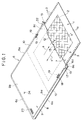
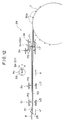
- a printing sheet 1 is a substantially rectangular sheet of about 200 microns in thickness made of a thermoplastic resin such as polyethylene resin.
- Image data 2 is formed with high precision in the form of relief of the order of submicrons in a substantially rectangular region, shown with diagonal hatching in Fig. 1, of the surface 1a of the printing sheet 1.
- a row of sprocket holes 3 is formed along each side, the left side and the right side, of the printing sheet 1; the two rows are parallel and the sprocket holes 3 are spaced at a fixed pitch.
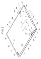
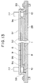
- a printing sheet jacket 6 is substantially rectangular and has the form of a flat bag with three sides 6a, 6b and 6c closed in a substantial C-shape and a printing sheet removal/insertion opening 7 provided at the fourth side 6d.
- This printing sheet jacket 6 can be simply manufactured by horizontally superposing a substantially rectangular base sheet 8 and cover sheet 9 of thickness approximately 200 microns made of a thermoplastic resin such as polyethylene resin or the like or PET resin sheet having its surface coated with about 5 to 40 ⁇ m of a readily thermally decomposing material (for example a nitrocellulose compound) and thermally sealing three of the sides 6a, 6b and 6c in a substantial C-shape of a predetermined width (thermally fusing together the base sheet 8 and the cover sheet 9 by heating them while pressing them together).
- a readily thermally decomposing material for example a nitrocellulose compound
- the left and right side edges of the printing sheet jacket 6 are formed as a left/right parallel pair of belt-shaped roller press portions 10 of a predetermined width.
- the cover sheet 9 of the printing sheet jacket 6 has a horizontal ceiling portion 9b formed integrally atop a substantially C-shaped vertical portion 9a which projects vertically upward along the inside of the three edges 6a, 6b and 6c thermally sealed in a substantial C-shape, and a flat printing sheet accommodating space 11 of a height H1 greater than the thickness T1 of the printing sheet 1 is formed between the ceiling portion 9b of the cover sheet 9 and the base sheet 8.
- the printing sheet 1 is accommodated in the printing sheet accommodating space 11 with its front surface 1a facing upward and can be removed from and reinserted into the printing sheet accommodating space 11 through the printing sheet removal/insertion opening 7 in the direction of the arrows (a), a'.
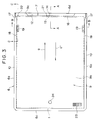
- a cutaway 12 is formed from the central portion to the left and right side portions of the opening end 9c, which is the end portion of the cover sheet 9 at the printing sheet removal/insertion opening 7 end, and an opening/closing flap 13 is formed integrally with the cover sheet 9 in the central portion of the cutaway 12.
- this opening/closing flap 13 is passed through a slot-shaped opening/closing flap lock hole 14 formed in the central portion of the opening end 8a of the base sheet 8, and this blocks the printing sheet removal/insertion opening 7 of the printing sheet jacket 6 and locks in the printing sheet 1 (prevents the printing sheet 1 from coming out of the printing sheet jacket 6) sheathed inside the printing sheet jacket 6.
- a left/right parallel pair of slits 15 cut out of the opening end 9c of the cover sheet 9 are formed in the cover sheet 9 at the left and right sides of the printing sheet removal/insertion opening 7, and the opening end 9c of the cover sheet 9 can open and close easily across its entire width in the direction of the arrows b, b' along a crease 16 connecting the deepest portions 15a of the left/right slits 15.
- a left/right pair of taper portions 17 tapering off in the printing sheet insertion direction (the direction of the arrow a') for guiding printing sheet insertion are formed integrally at the left and right sides of the printing sheet removal/insertion opening 7 from the deepest portions 15a of the left/right slits 15 to the left/right sides of the vertical portion 9a.
- a left/right pair of jacket holding holes 18 passing vertically through the base sheet 8 and the cover sheet 9 are formed in the left/right pair of roller press portions 10 in locations in the vicinity of the printing sheet removal/insertion opening 7 of the printing sheet jacket 6.
- Misloading (mis-insertion) detection holes 21, 22 constituting objects of detection of misloading detecting means for detecting misloading (mis-insertion) of the printing sheet jacket 6 into a printing sheet making machine and a printing machine to be discussed hereinafter are formed in the vicinity of the printing sheet removal/insertion opening 7 of the printing sheet jacket 6 in left/right positions asymmetrical with respect to the left-right direction center of the printing sheet jacket 6.
- the misloading detection hole 21 is formed to one side of the opening/closing flap 13 and the misloading detection hole 22 is disposed above the centerline of one of the rows of sprocket holes 3 in the printing sheet 1.
- a bar code label 23 for identifying the type of the printing sheet 1 sheathed inside the printing sheet jacket 6 (identifying its type in terms of whether or not it is a new printing sheet and what image data 2 is engraved on it in what colors, etc) is affixed to the upper side of the cover sheet 9 of the printing sheet jacket 6.
- an observation hole 24 for identifying the above-mentioned type of the printing sheet 1 visually is provided in the cover sheet 9 of the printing sheet jacket 6.
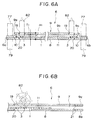
- image data 2 such as a photograph or the like is engraved in the form of relief in the front surfaces la of 1 to 4 printing sheets 1.
- the printing sheet making machine 27 is fitted with a jacket loading table 28 and a printing sheet feed and eject device 29 disposed thereon.
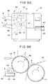
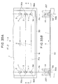
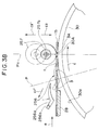
- a printing cylinder 30 Inside the printing sheet making machine 27 there are disposed a printing cylinder 30 and a laser block 34 which shines a laser beam CB emitted by a semiconductor laser 31 through a collimator lens 32 and an objective lens 33 onto the surface la of a printing sheet wound on the periphery of the cylinder 30.
- the laser block 34 is reciprocated in the axial direction of the cylinder 30 [perpendicular to the plane of the drawing of Fig. 8(B)].
- the printing machine 37 is provided with 1 to 4 jacket loading tables 38 and 1 to 4 printing sheet feed and eject devices 39 for loading, feeding and ejecting 1 to 4 printing sheet jackets 6, and inside the printing machine 37 there are disposed the same number of printing cylinders 40, pressure rollers 41 and ink units 45 comprising ink pans 42, ink rollers 43, and doctor blades 44, etc.
- Four colors of water-type ink 46 such as cyan, magenta, yellow and black are supplied color by color to the 4 ink pans 42.
- the printing machine 37 is provided with a cut paper tray 48 on which is stacked cut paper 47, the matter to be printed, and inside the printing machine 37 is mounted a cut paper circulating apparatus (not shown in the drawings) for circulating the cut paper 47 to the 1 to 4 pressure rollers 41 one after another.
- Fig. 9(A) shows a printing machine provided with two jacket loading tables 38, two printing sheet feed and eject devices 39, two cylinders 40, two pressure rollers 41 and two ink units 45.
- a printing sheet jacket 6 in which an unengraved printing sheet 1 is sheathed is loaded horizontally in the direction of the arrow (a) onto the jacket loading table 28 of the printing sheet making machine 27.
- the printing sheet feed and eject device 29 automatically pulls the printing sheet 1 out from inside the printing sheet jacket 6 in the direction of the arrow (a) and winds the printing sheet 1 onto the periphery of the cylinder 30 inside the printing sheet making machine 27, as shown in Fig. 8(B).
- so-called direct engraving wherein the printing sheet 1 is rapidly rotated in the direction of the arrow c by the cylinder 30 while the semiconductor laser 31 shines a laser beam LB onto the surface 1a of the printing sheet 1 while the laser block 34 is reciprocated in the axial direction of the cylinder 30 and color by color image data 2 of a photograph or the like is thereby engraved directly with high precision in the form of relief of the order of submicrons in the surface 1a of the printing sheet 1, is carried out on 1 to 4 printing sheets 1 one after another.
- digital information representing an image such as a photograph is taken from a multimedia source such as a photograph scanner or a digital VTR and electronically edited in an image processing computer or the like, and digital information for each of four colors such as cyan, magenta, yellow and black is obtained.
- the 1 to 4 printing sheets 1 are then put through the printing sheet making machine one after another and based on this color by color four-color digital information color by color image data 2 for each of the four colors is then separately engraved on the 1 to 4 printing sheets 1.
- Each engraved printing sheet 1 is automatically removed from the periphery of the cylinder 30 in the direction of the arrow a' and reinserted into its printing sheet jacket 6 by the printing sheet feed and eject device 29, whereby the engraving step is finished.
- the printing sheet jacket 6 is then removed from the jacket loading table 28 in the direction of the arrow a' and loaded into the printing machine 37.
- the 1 to 4 printing sheet jackets 6 containing the engraved printing sheets 1 of the different colors engraved color by color in the engraving step are severally loaded horizontally in the direction of the arrow (a) onto the 1 to 4 jacket loading tables 38 of the printing machine 37.
- the printing sheet feed and eject devices 39 automatically pull the printing sheets 1 out of their printing sheet jackets 6 in the direction of the arrow (a) and automatically wind them onto the peripheries of the 1 to 4 cylinders 40 inside the printing machine 37, as shown in Fig. 9(B).
- Cut paper 47 from the cut paper tray 48 shown in Fig. 9(A) is circulated around the 1 to 4 pressure rollers 41 and printing of the kind illustrated in Fig. 9(B) is carried out.
- the pressure rollers 41 which rotate at high speed in the direction of the arrow f in synchrony with the cylinders 40, feed the cut paper 47 past the cylinders 40 at high speed while pressing it against the surfaces la of the printing sheets 1, and the color by color image data 2 of a photograph or the like on the printing sheets 1 prints a sequentially colored image 4 on the cut paper 47 at high speed.
- jacket loading tables 28 and 38, the printing sheet feed and eject devices 29 and 39, and the cylinders 30 and 40 of the printing sheet making machine 27 and the printing machine 37 are of identical construction.
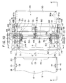
- the jacket loading table 28, the printing sheet feed and eject device 29 and the cylinder 30 of the printing sheet making machine 27 will now be described with reference to Figs. 10 to 29.
- a table cover 51 is horizontally mounted on a horizontal jacket loading table 28 and a printing sheet jacket 6 is horizontally loaded into a horizontal jacket loading space 52 formed between these two onto the jacket loading table 28 in the direction of the arrow (a) with its printing sheet removal/insertion opening 7 end at the front.
- Left/right side guides 53 for horizontally guiding the left and right sides of the printing sheet jacket 6 are formed integrally with the table cover 51 at the left and right sides thereof.
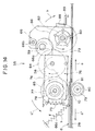
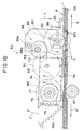
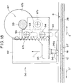
- the printing sheet feed and eject device 29 is mounted above the table cover 51 of the jacket loading table 28; this printing sheet feed and eject device 29 comprises left/right symmetrical pairs of jacket and printing sheet pulling in devices 55 and jacket holding devices 56, and is also provided with jacket central and side flap opening devices 57a and 57b.
- a drive shaft 58, a camshaft 59 and a sprocket shaft 60 are disposed horizontally crossing over the table cover 51 in the left-right direction and are mounted on a left/right pair of brackets 61.
- a motor 62 and a gear train 63 for reversibly rotationally driving the drive shaft 58 and a motor 64 and a gear train 65 for reversibly rotationally driving the camshaft 59 are mounted above the table cover 51.
- Three left/right pairs of cam mechanisms 66, 67 and 68, six cam mechanisms in total, are mounted at the left and right ends of the camshaft 59, and a cam mechanism 69 is mounted at the central portion of the camshaft 59.
- the left/right pairs of jacket and printing sheet pulling in devices 55 and jacket holding devices 56 and the jacket central and side flap opening devices 57a and 57b are driven by the motors 62 and 64, the gear trains 63 and 65, the drive shaft 58, the camshaft 59 and the cam mechanisms 66, 67, 68 and 69 in the manner described hereinafter.
- a number of sensors S1 to S8 constituting a controller for controlling the jacket and printing sheet pulling in devices 55, the jacket holding devices 56 and the jacket central and side flap opening devices 57a and 57b so that they operate sequentially based on predetermined sequences are provided.
- the sensors S1 to S6 each consist of a light emitting device LD and a light receiving device PD disposed so as to perform light detection vertically through the jacket loading table 28 and the table cover 51.
- the sensors S7 and S8 comprise photocouplers which perform detection on a pair of slit discs 70 mounted on the left and right ends of the camshaft 59.
- a left/right pair of jacket stoppers 71 are mounted on the left and right sides of the arrow (a) direction end of the jacket loading table 28.
- the left/right jacket and printing sheet pulling in devices 55 are constructed left/right symmetrically and are provided with a left/right pair of seesaw-style pivoting arms 76 each made up of first and second arms 73 and 74 mounted pivotally in the direction of the arrows h, h' on the left and right end portions of the drive shaft 58, which doubles as a supporting shaft for them, and limiter springs 75 consisting of tension springs or the like which pull the first and second arms 73 and 74 toward each other.
- a left/right pair of drive rollers 77 which are jacket pulling in means, are rotatably mounted via a left/right pair of horizontal roller shafts 78 on the left/right pair of second arms 74 on the arrow a' direction side of the drive shaft 58.
- the left/right pair of drive rollers 77 comprise high friction rollers such as rubber rollers and a left/right pair of torque limiters 77a are incorporated therein.
- a left/right pair of pinch rollers 79 are rotatably mounted via a horizontal roller shaft 80 on the underside of the jacket loading table 28 directly below and facing the pair of drive rollers 77.
- a left/right pair of long holes 81 are formed in the table cover 51 and in the jacket loading table 28 to allow the left/right pairs of drive rollers 77 and pinch rollers 79 to project therethrough.
- the left and right ends of the sprocket shaft 60 are rotatably attached to the left/right pair of first arms 73 on the direction (a) side of the drive shaft 58.
- a left/right pair of sprockets 82 which are printing sheet pulling in means, are mounted on the left and right ends of the sprocket shaft 60.
- a left/right pair of long holes 83 are formed in the table cover 81 and the jacket loading table 28 to allow the left/right pair of sprockets 82 to project therethrough.
- a left/right pair of cam mechanisms 66 which are control mechanisms, mounted on the left/right end portions of the camshaft 59, each comprise a cam 66a mounted on the camshaft 59, a driven roller 66b, which is a cam follower, rotatably mounted on the first arm 73, and a cam spring 66c, consisting of a tension spring or the like, which rotationally urges the first arm 73 in the direction of the arrow h and presses the driven roller 66b onto the upper portion of the periphery of the cam 66a.
- the first and second arms 73 and 74 are urged toward each other in the direction of the arrows h, h' by the limiter spring 75 and have their positions with respect to each other restricted by a stopper 87 disposed between them.
- the first arm 73 rotationally urged by the cam spring 66c in the direction of the arrow h about the camshaft 58, has its position restricted by being caused by a rubber cushion 88 to abut with the top of a stopper 89 mounted on the table cover 51.
- the rotational drive of the drive shaft 58 is transmitted to the roller shaft 78 and the sprockets 82 via the drive mechanism made up of the drive gears 84 and the driven gears 85 and 86, and the left right pairs of drive rollers 77 and sprockets 82 are thereby forward/reverse rotationally driven simultaneously.
- the cam angle 0° and 180° positions of the cam 66a are detected by the sensor S7.
- the drive rollers 77 and the sprockets 82 are simultaneously forward/reverse rotationally driven by the single drive shaft 58 via the drive mechanism made up of the drive gears 84 and the driven gears 85 and 86, the two types of actuator that are the drive rollers 77 and the sprockets 82 can be simultaneously forward/reverse rotationally driven by the single motor 62.
- a left/right pair of jacket holding devices 56 are of left/right symmetrical construction and comprise a left/right pair of vertical slider mounting plates 92 mounted on the table cover 51 and a left/right pair of sliders 95 mounted on side surfaces of these slider mounting plates 92 by way of a plurality of guide holes 93 and guide pins 94 in such a way that they can move vertically in the direction of the arrows i, i'.
- a left/right pair of holding pins 96 which are jacket holding means, are fixed to the undersides of the left/right pair of sliders 95 and project perpendicularly downward therefrom.
- a left/right pair of cam mechanisms 67 which are drive mechanisms for raising and lowering the left/right pair of holding pins 96 in the direction of the arrows i, i', are each made up of a cam 67a mounted on the camshaft 59, a cam driven roller 67b, which is a cam follower, rotatably mounted on the slider 95, and a cam spring 67c, consisting of a tension spring or the like, which urges the slider 95 upward in the arrow i direction and presses the cam driven roller 67b against the underside of the periphery of the cam 67a.
- a taper 96a is formed on the lower end of each of the left/right pair of holding pins 96. Holes 97 are formed in the table cover 51 and the jacket loading table 28 to allow the left/right pair of holding pins 96 to pass therethrough.
- the left/right cam mechanisms 67 cause the left/right pairs 96 of the left/right jacket holding devices 56 to ascend or descend in the direction of the arrows i, i'.
- the tapers 96a are provided on the lower ends of the left/right pair of holding pins 96, even if the printing sheet jacket 6 is slightly out of the above-mentioned fixed position, the guiding action of the tapers 96a serves to automatically bring the printing sheet jacket 6 into the fixed position as the holding pins 96 descend.
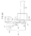
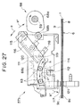
- This jacket central flap opening device 57a is a device for opening the flap of the central part of the opening end 9c of the cover sheet 9 of the printing sheet jacket 6.
- This jacket central flap opening device 57a has a vertical flap opening arm mounting plate 100 mounted on the central portion of the table cover 51, a flap opening arm 102 and a cam driven arm 103 mounted pivotally in the direction of the arrows j, j' on a side surface of the flap opening arm mounting plate 100 via a horizontal supporting shaft 101, and a central flap opening suction pad 104, which is central flap opening means, and a central pushing pin 105, which is central pushing means, mounted on the underside of the end portion of the flap opening arm 102 and projecting perpendicularly therefrom.
- the central cam mechanism 69 which is a control mechanism, mounted at the center of the camshaft 59, is made up of a cam 69a mounted on the camshaft 59, a cam driven roller 69b, which is a cam follower, rotatably mounted on the cam driven arm 103, and a cam spring 69c, consisting of a tension spring or the like, which at all times pushes the cam driven roller 69b against the periphery of the cam 69a.
- the flap opening arm 102 is mounted on the support shaft 101 in such a way that it can pivot in the direction of the arrows j, j', and the cam driven arm 103 is mounted on this flap opening arm 102 via a plurality of adjustment screws 106 in such a way that its length in the direction of the arrows k, k' is adjustable.
- Two holding suction pads 107 and 108 which are central holding means, are vertically mounted under the jacket loading table 28 in positions directly below the central flap opening suction pad 104 and the central pushing pin 105 respectively.
- the central flap opening suction pad 104 and the central holding suction pads 107 and 108 are constructed as vacuum suction-gripping means connected to a vacuum pump (not shown in the drawings).
- the flap opening arm 102 is caused to pivot up and down in the direction of the arrows b, b' by the cam driven roller 69b which is at all times pushed against the periphery of the cam 69c by the cam spring 69c and rolls along the periphery of the cam 69a.
- the central flap opening suction pad 104 and the central holding suction pads 107 and 108 are caused by suction from the vacuum pump to suction-grip the central portions of the upper side of the cover sheet 9 and the underside of the base sheet 8 respectively.
- the flap opening arm 102 returns a little in the arrow b' direction and returns the opening end 9c of the cover sheet 9 suction-gripped by the central flap opening suction pad 104 in the arrow b' direction a little to a predetermined opening stroke ⁇ 2 wherein the cover sheet 9 is unstressed, and the printing sheet removal/insertion opening 7 is held open to a predetermined extent.
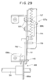
- This jacket side flap opening device 57b is a device for opening the left and right side portions of the opening end 9c of the cover sheet 9 of the printing sheet jacket 6 and is of left/right symmetrical construction.
- the jacket side flap opening device 57b comprises a left/right pair of vertical flap opening arm mounting plates 111, a left/right pair of circular arcuate holes 112 formed in the left/right pair of flap opening arm mounting plates 111, a left/right pair of flap opening arms 114 mounted via left/right pairs of rollers 113 on side surfaces of the left/right pair of flap opening arm mounting plates 111 in such a way that they can move circularly along the left/right pair of circular arcuate holes 112 in the direction of the arrows n, n', a left/right pair of drive arms 116 mounted on the opposite side surfaces of the left/right pair of flap opening arm mounting plates 111 from the left/right pair of flap opening arms 114 at their upper ends via a left/right pair of support shafts 115 in such a way that they can pivot in the direction of the arrows o, o', and a left/right pair of side flap opening suction pads 117, which are side flap opening means, mounted perpendicularly on the underside
- the left/right pair of circular arcuate holes 112 are formed in circular arcs of radius of curvature R with the crease line 16 of the opening end 9c of the cover sheet 9 as a virtual center. Therefore, the left/right pair of flap opening arms 114, engaged with these circular arcuate holes 112 via the pairs of rollers 113, move circularly along these circular arcuate holes 112 in the direction of the arrows n, n' with the crease line of the opening end 9c of the cover sheet 9 of the printing sheet jacket 6 as a virtual center.
- a left/right pair of side cam mechanisms 68 which are control mechanisms, mounted at the left and right end portions of the camshaft 59, each comprise a cam 68a mounted on the camshaft 59, a cam driven roller 68b, which is a cam follower, rotatably mounted on the drive arm 116, and a cam spring 68c, consisting of a tension spring or the like, which at all times pushes the cam driven roller 68b against the periphery of the cam 68a.
- the lower ends of the left/right pair of drive arms 116 are linked to the left/right pair of flap opening arms 114 via link pins 119 mounted on the drive arms 116 and passing through openings 118 in the left/right pair of opening arm mounting plates 111 into linking holes 120 formed in the flap opening arms 114.
- a left/right pair of side holding suction pads 121 which are side holding means, are perpendicularly mounted underneath the jacket loading table 28 and directly below the left/right pair of side flap opening suction pads 117.
- the left/right pairs of side flap opening suction pads 117 and side holding suction pads 121 are constructed as vacuum suction-gripping means connected to a vacuum pump.
- each cam mechanism 68 when the cam 68a of each cam mechanism 68 is rotated in the direction of the arrow by the camshaft 59 from the cam angle 180° shown in Fig. 26 toward the cam angle 0°, the flap opening arm 114 is caused to reciprocate in the direction of the arrows n, n' via the drive arm 116 by the cam driven roller 68b which is at all times pressed against the periphery of the cam 68a by the cam spring 68c and rolls around the periphery of the cam 68a.
- the pair of rollers 113 of the opening arm 114 move circularly in the circular arcuate holes 112 in the direction of the arrows n, n' and the side flap opening suction pads 117 consequently move circularly in the direction of the arrows n, n' with the hereinafter discussed crease 16 of the cover sheet 9 of the printing sheet jacket 6 as a virtual center.
- the left/right pair of side flap opening suction pads 117 are pressed down in the arrow b' direction by the flap opening arms 114 onto the left and right side portions of the opening end 9c of the cover sheet 9 of the printing sheet jacket 6 loaded in the above-mentioned fixed position on the jacket loading table 28, and also the left/right side portions of the opening end 8a of the base sheet 8 of the printing sheet jacket 6 are pushed by the left/right pair of side flap opening suction pads 117 down onto the left/right pair of side holding suction pads 121.
- the left/right pair of side flap opening suction pads 117 and the left/right pair of side holding suction pads 121 are caused by the suction force of the vacuum pump to suction-grip the left and right side portions of the cover sheet 9 and the base sheet 8.
- the cams 66a to 69a of the cam mechanisms 66 to 69 are set to be at cam angle 0° before the start of printing sheet feeding.
- the motor 62 is driven to rotate forward and, a shown in Fig. 15, the rotation of the left/right pair of drive rollers 77 in the direction of the arrow automatically pulls the printing sheet jacket 6 into the jacket loading space 52 in the arrow (a) direction.
- the sensor S5 detects the presence or otherwise of the misloading detection hole 21 formed in a left/right asymmetrical position in the printing sheet jacket 6, and top/bottom and front/rear misloading (mis-insertion) of the printing sheet jacket 6 can thereby be detected.
- the left/right pair of drive rollers 77 are immediately driven to rotate in reverse and automatically eject the printing sheet 6 in the arrow a' direction, or the fact that the printing sheet jacket 6 has been incorrectly loaded is made known to the operator by some kind of display or the like.
- the vacuum pump is activated and the motor 64 is driven to rotate in reverse to change the cam angle of the cams 66a to 69a of the cam mechanisms 66 to 69 from 180° to 0°.
- the opening end 9c of the cover sheet 9 is unforcedly and smoothly opened across its entire width about the crease 16, and the printing sheet removal/insertion opening 7 is opened across its entire width.
- the left/right pair of drive rollers 77 are withdrawn to above the printing sheet jacket 6.
- the left/right pair of holding pins 96 are inserted into the left/right pair of jacket holding holes 18 in the printing sheet jacket 6 and the printing sheet jacket 6 is thereby held in the above-mentioned fixed position.
- the left/right pair of sprockets 82 engage with the sprocket holes 3 in the left and right sides of the printing sheet 1 inside the printing sheet jacket 6.
- the motor 62 is again driven to rotate and, as shown in Fig. 16, the rotational force of the left/right pair of sprockets 82 in the direction of the arrow drives the sprocket holes 3 in the direction of the arrow and the printing sheet 1 is automatically pulled out from inside the printing sheet jacket 6 in the direction of the arrow (a).
- the sensor S6 counts the number of sprocket holes 3 and the extent to which the printing sheet 1 has been pulled out in the arrow (a) direction is thereby detected. This sensor S6 can also detect the misloading detection hole 22 in the printing sheet jacket 6.
- the cylinder 30 When the printing sheet 1 has been pulled out of the printing sheet jacket 6 in the arrow (a) direction as far as a predetermined position, as shown in Figs. 11 and 12, the cylinder 30 is driven to rotate in the direction of the arrow and sprocket pins 30a provided around the peripheries of both ends of the cylinder 30 engage with the sprocket holes 3 in the left and right sides of the printing sheet 1 and, as shown by dotted lines in Figs. 11 and 12, the printing sheet 1 is automatically wound onto the periphery of the cylinder 30.
- the printing sheet 1 ends up completely out from inside the printing sheet jacket 6 and wound around the cylinder 30, as shown in Figs. 8(B) and 9(B).
- the cover sheet 9 is opened using the suction force of a vacuum pump connected to the central and side flap opening suction pads 104 and 117; by detecting the degree of vacuum created by the vacuum pump in the central and side flap opening suction pad 104 and 117 system with a pressure sensor, indirect detection of whether or not the cover sheet 9 has opened is carried out.
- the vacuum pump When the printing sheet 1 is to be ejected, the vacuum pump is operating, the cams 66a to 69a are set to cam angle 66a to 69a, the cover sheet 9 of the printing sheet jacket 6 held in the jacket loading space 52 is open, and the printing sheet removal/insertion opening 7 is standing by still open across its entire width.
- the printing sheet 1 is then automatically returned from the cylinder 30 into the printing sheet jacket 6 through the printing sheet removal/insertion opening 7 in the arrow a' direction.
- the motor 62 is driven to rotate in reverse and the left/right pair of sprockets 82 are thereby driven to rotate in reverse, the left/right pair of sprockets 82 drive the sprocket holes 3 in the left and right sides of the printing sheet 1, and the printing sheet 1 is automatically returned in the arrow a' direction into the printing sheet jacket 6.
- the speed of rotation of the left/right pair of sprockets 82 is made slightly higher than the speed at which the cylinder 30 reels out the printing sheet 1; this difference in speed is absorbed by the torque limiters 82a of the sprocket shaft 60, and thereby the printing sheet 1 can be returned in the arrow a' direction into the printing sheet jacket 6 without any slackness.
- the sensor S5 detects this and the motor 62 is automatically stopped.
- the motor 64 is then driven to rotate forward and the cams 66a and 69a are set to the cam angle 180° whereby the left/right pair of drive rollers 77 are pushed down onto the printing sheet jacket 6 and the left/right pair of holding pins 96 and the sprockets 82 are withdrawn to above the printing sheet jacket 6.
- the motor 62 is then driven to rotate in reverse, and the printing sheet jacket 6 is automatically ejected from inside the jacket loading space 52 by a certain fixed amount in the arrow a' direction.
- the completion of the ejection of the printing sheet jacket 6 in the direction a' is detected by the sensor S2, and the motor 62 is automatically stopped.
- the motor 64 again sets the cams 66a to 69a to the cam angle 0° and thereby returns the apparatus to the initial printing sheet feeding state.
- the apparatus goes into a standby state, and even if the printing sheet jacket 6 is manually inserted in the arrow (a) direction again automatic printing sheet feeding will not be carried out.
- this electronic gravure printing system because the system can be operated without the operator touching the printing sheet 1 at all, the adhesion of dust and the like and the occurrence of scratching on the surface 1a of the printing sheet 1 on which the image data 2 is formed can be completely prevented and stable printed matter can be obtained. Also, by developing this system, an electronic gravure printing system which can be run unmanned can easily be realized.
- the devices for winding the printing sheet 1 onto the cylinders 30 and 40 of the printing sheet making machine 27 and the printing machine 37 discussed above are of identical construction.
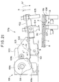
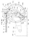
- the printing sheet winding device 251 of the printing sheet making machine 27 will now be described, with reference to Figs. 30 to 68.
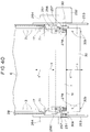
- a left/right pair of cylinder support frames 253 are perpendicularly mounted apart from each other on a chassis 252, and a cylinder 30 is disposed horizontally between these cylinder support frames 253.
- the axial direction (the left-right direction) ends of a horizontal shaft 30b fixed at the center of the cylinder 30 are rotatably mounted on the left/right pair of cylinder support frames 253 via a left/right pair of bearings (not shown in the drawings).
- the above-mentioned jacket loading table 28 is mounted horizontally between the left/right pair of cylinder support frames 253, and the forward end of the jacket loading table 28 in the arrow (a) direction is in the vicinity of the upper part of the cylinder 30.
- the cylinder drive mechanism 229 consists of a drive motor 230, which is cylinder rotational drive means, mounted on the chassis 252 and linked by a belt transmission mechanism 231 to one end of the shaft 30b.
- a rotary encoder 232 which is cylinder position detecting means, is directly coupled to the other end of the shaft 30b and is mounted on a side surface of one of the cylinder support frames 253.
- the arrangement is such that the cylinder 30 is freely forward/reverse rotationally driven in the direction of the arrows c, c' by the drive motor 230, detection of the position of the cylinder 30 in the direction of the arrows c, c' is performed by the rotary encoder 232, and the cylinder 30 can be stopped at designated positions.
- a row of sprocket pins 30a is provided at each end of the periphery of the cylinder 30; the sprocket pins 30a of both rows are spaced at the same pitch and are located in identical positions around the periphery of the cylinder 30.
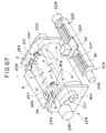
- a printing sheet winding device 251 which will be further discussed hereinafter is mounted between the left/right pair of cylinder support frames 253.
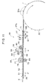
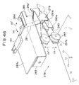
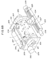
- a printing sheet 1 automatically pulled out of a printing sheet jacket 6 loaded onto the jacket loading table 28 in the arrow (a) direction by the printing sheet feed and eject device 29 discussed above is automatically wound in the arrow c direction onto the periphery of the cylinder 30 by the two rows of sprocket pins 30a on the cylinder 30, as shown in Fig. 68, in a manner discussed hereinafter.
- a laser block transport mechanism 223 moves a laser block transport plate 224 on which the laser block 34 is mounted in the direction of the arrows s, s' by means of a feed screw 227 forward/reverse rotationally driven by a drive motor 226 mounted at one end of the feed screw 227 while guiding the laser block transport plate 224 between a pair of slide guides 225 parallel with the axis of the cylinder 30.
- a rotary encoder 228 which detects the position in the direction of the arrows s, s' of the laser block 34 is directly coupled to the other end of the feed screw.
- the printing sheet 1 is automatically unwound from the periphery of the cylinder 30 in the arrow c' direction and is automatically conveyed in the arrow a' direction into the printing sheet jacket 6.
- the printing sheet winding device 251 will now be described in detail.
- the two rows of sprocket pins 30a provided at a fixed pitch around the ends of the periphery of the cylinder 30 each consist of for example 12 sprocket pins 30a spaced at 30°.
- the arrangement is such that sprockets 30a of the two rows of sprockets 30a enter every third sprocket hole 3 of the two rows of sprocket holes 3 formed along the left and right sides of the printing sheet 1, and the printing sheet 1 is wound around the periphery of the cylinder 30 through an angle of 360° plus ⁇ .
- the pitch P1 in the circumferential direction of the cylinder and the span P2 in the axial direction of the cylinder of the two rows of sprocket pins 30a on the periphery of the cylinder 30 are made slightly larger (about 0.01 to 0.03mm) than the distance between every third sprocket hole 3 and the span between the two rows of sprocket holes 3, i.e. than the engaging pitch P3 and the engaging span P4.
- each of the sprocket pins 30a has a cylindrical surface 30a1 formed at its base portion, a tapered surface 30a2 formed above the cylindrical surface 30a, and an R surface 30a3 formed atop the cylindrical surface 30a2.
- the sprocket holes 3 are press fitted over the cylindrical surfaces 30a1 of the sprocket pins 30a.
- the width through which the sprocket holes 3 along the side of the printing sheet 1 corresponding to the sprockets 30a disposed along a reference position P5 at one end of the cylinder 30 are press fitted over those sprockets 30a is made large, and the width through which the sprocket holes 3 along the other side of the printing sheet 1 corresponding to the sprockets 30a disposed along a non-reference position P6 at the other end of the cylinder 30 is made small.
- the jacket loading table 28 is disposed on a horizontal tangent of the top of the periphery of the cylinder 30, and the vertical position line connecting the axis of rotation of the cylinder 30 and the intersection of this tangent and the top of the cylinder 30 is set to be the press fitting position P11 of the sprocket holes 3 with respect to the sprocket pins 30a.
- a position approximately 15° behind this press fitting position P11 in the arrow c' direction is set to be a reference position P12 of the circumferential direction of the cylinder 30, and a position about 30° in front of the press fitting position P11 in the arrow c' direction is set to be a printing sheet clamping position P13.
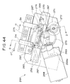
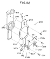
- a left/right pair of printing sheet pressing plates 256 which serve as both printing sheet lifting-off means and printing sheet pressing means, a left/right pair of printing sheet press fitting rollers 257 constituting printing sheet press fitting means, a printing sheet clamper 258, a left/right pair of locking pins 259 which constitute clamper control means, a magnet 260 for attracting the printing sheet clamper 258, and a printing sheet guide 261.
- the left/right pair of printing sheet pressing plates 256 are disposed left/right symmetrically at the inner sides of the left/right pair of cylinder support frames 253 in positions at the reference position P12 over the two rows of sprocket pins 30a of the cylinder 30.
- a left/right pair of printing sheet pressing plate drive devices 264 which drive this left/right pair of printing sheet pressing plates 256 are mounted left/right symmetrically on the outer sides of the left/right pair of cylinder support frames 253.
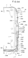
- the printing sheet pressing plates 256 are made of plastic and each have an elastic twin-pronged arm 256a and a slot 256b open in the arrow (a) direction formed in their central portion. Base portions of the printing sheet pressing plates 256 pass through long holes 265 formed diagonally in the cylinder support frames 253 and project to the outer sides of the cylinder support frames 253 and are fixed to support plates 266 disposed on the outer sides of the cylinder support frames 253.
- the support plates 266 are each guided by a total of four guide rollers 267 mounted on the outer side of the respective cylinder support frame 253 so that the printing sheet pressing plates 256 move in the direction of the arrows c, c', which is diagonally up and down with respect to the position P12.
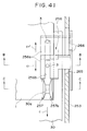
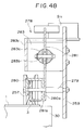
- the printing sheet pressing plate drive devices 264 each comprise a worm 270 linked by a coupling 269 to a drive motor 268 mounted on a bracket 268a, a worm wheel 271 meshing with the worm 270, a pinion 273 linked via an intermediate gear 272 to the worm wheel 271, a rack 274 fixed to the supporting plate 266 and meshing with the pinion 273, a shutter plate 275 fixed to the side surface of the rack 274, and a pair of sensors S9, S10, comprising photocouplers, which are switched ON and OFF by the shutter plate 275.
- the printing sheet pressing plates 256 are moved integrally with the supporting plates 266 by the drive motor 268 via the worms 270, the worm wheels 271, the intermediate gears, the pinions 273 and the racks 274 to the operating positions shown by solid lines in Figs. 30 and 44; the sensors S9 detect the movement of the shutter plate 275, and the drive motor 268 is automatically stopped.
- the left/right pair of printing sheet press fitting rollers 257 are made of plastic, and each has a central circular groove 257a formed around the central portion of its periphery. These left/right pair of printing sheet press fitting rollers 257 are disposed left/right symmetrically inside the left/right pair of cylinder support frames 253 in positions at the press fitting position P11 over the two rows of sprocket pins 30a of the cylinder 30.
- the left/right pair of printing sheet press fitting roller drive devices 278 which drive these left/right pair of printing sheet press fitting rollers 257 are mounted left/right symmetrically on the inner sides of the left/right pair of cylinder support frames 253.
- Each printing sheet press fitting roller drive device 278 comprises a supporting shaft 279 horizontally mounted on the respective cylinder support frame 253; a supporting arm 280 rotatably mounted on the supporting shaft 279 and having the printing sheet press fitting roller 257 rotatably mounted on its end; a drive arm 281 pivotally mounted on the same supporting shaft 279; a limiter spring 282, consisting of a tension spring, fitted between the supporting arm 280 and the drive arm 281; a plunger solenoid 283, which is means for driving the drive cam 281 by means of a plunger 283a, mounted on the cylinder support frame 253; a stopper 285 of the drive arm 281; a return spring 284 of the plunger 283a, consisting of a tension spring; and a microswitch S11 turned ON and OFF by the drive arm 281.
- the plunger 283a and the drive arm 281 are linked by a pin 283a, and the stopper 285 is formed integrally with the bracket 283c of the plunger solenoid
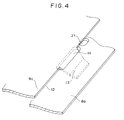
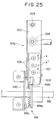
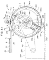
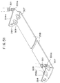
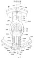
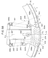
- the printing sheet clamper 258 is a belt-shaped plate made of a strongly magnetic material such as steel plate, and the overall length of this printing sheet clamper 258 is slightly greater than the overall length of the cylinder. Also, this printing sheet clamper 258 is curved in a circular arc along the periphery of the cylinder in a direction normal to its length direction. This printing sheet clamper 258 is pressed against and separated from the periphery of the cylinder while being held parallel with the axis of the cylinder by a left/right pair of printing sheet clamper support mechanisms 288.
- the left/right pair of printing sheet clamper support mechanisms 288 are left/right symmetrically mounted on the ends of the cylinder.
- the printing sheet clamper support mechanisms 288 each comprise a rotary support table 290 rotatably mounted via a bearing 289 on the left/right ends of the shaft 30b of the cylinder and a clamper support plate 293 mounted on the side of the rotary support table 290 slidably with respect to the rotary support table 290 in the direction of the arrows c4, c4', which is a direction orthogonal to the axial direction of the cylinder, via a pair of screws/guide pins 291 and a pair of long holes 292.
- a left/right pair of bent pieces 258a are each bent into a right angle toward the center of the cylinder at the ends of the printing sheet clamper 258.
- a left/right pair of support pin mating holes 294 are formed in the ends of the left/right pair of bent pieces 258a in positions biased to one side in the circumferential direction of the cylinder from the center P14 of the printing sheet clamper 258 in the circumferential direction of the cylinder.
- a left/right pair of support pin mating holes 295 formed in positions slightly biased in one direction from the above-mentioned center P14 in the ends of the left/right symmetrical left/right pair of clamper support plates 293 and the left/right pair of support pin mating holes 294 in the printing sheet clamper 258 are pivotally linked to each other by a left/right pair of support pins 296.
- the ends of the printing sheet clamper 258 are supported by the left/right pair of clamper support plates 293 and this printing sheet clamper 258 is movable in the direction of the arrows c4, c4', which is a direction orthogonal to the axial direction of the cylinder, while being held parallel to the cylinder, and this printing sheet clamper 258 can pivot with respect to the left/right pair of clamper support plates 293 about the left/right pair of support pins 296 in the direction of the arrows c5, c5' shown in Figs. 57 and 58.
- a left/right pair of spring attachment plates 297 are left/right symmetrically fixed by fixing screws 298 to the side surfaces of the left/right pair of rotary support plates 290 in positions peripheral to the bearings 289 so as to lie across the left/right pair of clamper support plates 293.
- Left/right pairs of pressure springs 301 and 302, consisting of tension springs, four springs in total, are fitted between spring anchorages 299a and 299b formed on the left/right pair of spring attachment plates 297 and spring anchorages 300a and 300b formed respectively on the opposite end portions of the bent pieces 258 from the support pin mating holes 294 and side portions of the left/right pair of clamper support plates 293.
- the printing sheet clamper 258 is pivotally urged in the arrow c5 direction with respect to the left/right pair of clamper support plates 293 about the left/right pair of support pins 296 by the left/right pair of pressure springs 301, and the printing sheet clamper 258 and the left/right pair of clamper support plates 293 are together strongly urged in the direction c4 with respect to the left/right pair of rotary support plates 290 by the left/right pairs, four springs in total, of pressure springs 301 and 302.
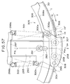
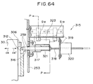
- a cam mechanism 305 constituting part of a clamper control mechanism for effecting clamping and unclamping of the printing sheet clamper 258 will be described.
- This cam mechanism 305 is made up of a left/right pair of concentric circular cams 306 fixed with screws to the ends of the cylinder around the vicinity of the periphery thereof, and left/right pairs of cam follower rollers 307, 308, consisting of bearings, rotatably mounted on the inner sides of the left/right pair of bent pieces 258 of the printing sheet clamper 258 in positions on opposite sides of the center P14 in the circumferential direction of the cylinder.
- the left/right pairs of cam follower rollers 307 and 308 are pressed in the arrow c4 direction against circular peripheral surfaces 306a, concentric with the cylinder, of the left/right pair of cams 306 by the left/right pairs of springs 301 and 302.
- a left/right pair of concave portions 306b into which the left/right pairs of cam follower rollers 307, 308 can descend simultaneously are formed in parts of the peripheral surfaces 306a of the left/right pair of cams 306.
- a fixed position lock mechanism 311 constituting another part of the printing sheet clamper control mechanism, for locking and unlocking the left/right pair of printing sheet clamper support mechanisms 288 in the printing sheet clamping position P13 shown in Figs. 30 to 33, will be described.
- This fixed position lock mechanism 311 is made up of a left/right pair of slots 312 formed in the opposite ends of the left/right pair of rotary support plates 290 from the printing sheet clamper 258 and a left/right pair of locking pins 259 free to enter and exit this left/right pair of slots 312 in the direction of the arrows c6, c6', parallel to the axis of the cylinder.
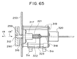
- Each lock pin drive mechanism 315 is mounted left/right symmetrically on the printing sheet clamping position P13 on the outer sides of the left/right pair of cylinder support frames 253.
- Each lock pin drive mechanism 315 is made up of a locking pin guide 317 which guides the respective locking pin 259 in and out through a through hole 316 formed in the respective cylinder support frame 253 in the direction of the arrows c6, c6'; a feed screw 318 disposed coaxially with the lock pin 259 at the opposite end of the lock pin 259 from the cylinder; a drive motor 320, mounted on a bracket 319, which moves the feed screw 318 in the direction of the arrows c6, c6'; a return spring 321, consisting of a compression spring, which at all times pushes the lock pin 259 against the end of the feed screw 318 in the arrow c6' direction; a shutter plate 323, fitted on the feed screw 318 side end portion of the lock pin 259 and guided by a guide shaft 322 parallel to the
- a magnet 260 is recessed in the periphery of the cylinder in a roughly central position P15 in the axial direction of the cylinder, whereby the roughly central portion in the length direction of the printing sheet clamper 258 pressed against the periphery of the cylinder in the printing sheet clamping position P13 is pulled against the periphery of the cylinder by magnetic attraction.
- the printing sheet guide 261 is mounted on the chassis 252 in parallel with the cylinder and is below the arrow c' direction side vicinity of the printing sheet clamper 258 when the printing sheet clamper 258 is in position in the printing sheet clamping position P13.
- a printing sheet jacket 6 is loaded onto the jacket loading table 28 of the printing sheet feed and eject device 29 shown in Figs. 10 to 12, and when the sensor S2 detects the printing sheet jacket 6 the automatic winding of the printing sheet 1 onto the periphery of the cylinder begins.
- the cylinder is driven in the direction of the arrow c by the cylinder drive mechanism 229, and, based on detection of the position of the cylinder by the rotary encoder 232, the left/right pair of printing sheet clamper support mechanisms 288 are stopped in the printing sheet clamping position P13.
- the left/right pair of lock pins 259 are driven in the direction of the arrow c6 by the left/right pair of lock pin drive mechanisms 315 shown in Figs. 63 to 66, and, as shown in Figs. 55 and 56, the left/right pair of lock pins 259 are inserted in the arrow c6 direction into the left/right pair of slots 312 in the left/right pair of rotary support plates 290.
- the left/right pairs of cam follower rollers 307, 308 of the left/right pair of cam mechanisms 305 are pushed up from the concave portions 306b of the left/right pair of cams 306 onto the outer peripheral surfaces 306a, and, as shown in Figs. 30 and 59 with broken lines, the printing sheet clamper 258 is separated from the periphery of the cylinder in the arrow c4' direction against the resistance of the left/right pairs of pressure springs 301, 302 while remaining parallel to the cylinder, and the printing sheet clamper 258 is thereby unclamped.
- first pins 30A which are a left/right pair of reference pins among the two rows of sprocket pins 30a on the periphery of the cylinder 30, are brought into the reference position P12, as shown in Fig. 37 with broken lines, and the cylinder is stopped.
- the automatic pulling in of the printing sheet jacket 6 in the direction of the arrow (a) to the above-mentioned fixed position and the automatic pulling out of the printing sheet 1 in the direction of the arrow (a) from inside the printing sheet jacket 6 are started by the printing sheet feed and eject device 29, shown in Figs. 10 to 12, and, as shown in Figs. 30 and 37, the leading end of the printing sheet 1 is fed roughly tangentially to the cylinder in the direction of the arrow (a) to the press fitting position P11 of the cylinder.
- the sensor S6 of the printing sheet feed and eject device 29 counts the sprocket holes 3 of the printing sheet 1 being fed in the direction of the arrow (a) and thereby detects the extent to which the printing sheet 1 has been pulled out in the direction of the arrow (a).
- the left/right pair of first pins 30A of the cylinder start to move from the reference position P12 toward the press fitting position P11.
- the left/right pair of printing sheet pressing plate drive devices 264 and the left/right pair of printing sheet press fitting roller drive devices 278 shown in Figs. 43 to 45 and 46 to 48 lower the left/right pair of printing sheet pressing plates 256 and the left/right pair of printing sheet press fitting rollers 257 respectively from the non-operating positions and non-pressing positions shown with broken lines in Fig. 37 into the operating positions and pressing positions shown with solid lines in Fig. 37 in the direction of the arrow c1 and the direction of the arrow c3.
- the twin-pronged arms 256a of the left/right pair of printing sheet pressing plates 256 having the slots 256b in their central portions, press the leading end of the printing sheet 1 down elastically in the direction of the arrow c1 onto the periphery of the cylinder 30 on both sides of each of the left/right pair of first pins 30A.
- the left/right pair of printing sheet press fitting rollers 257 having the circular grooves 257a around their central portions, elastically press the leading end of the printing sheet 1 in the direction of the arrow c3 onto the periphery of the cylinder 30 on both sides of the locuses of movement of the two rows of sprocket pins 30a on the cylinder.
- the cylinder continues to rotate at low speed, and by being pulled in the direction of the arrow c by the left/right pair of first pins 30A the printing sheet 1 is automatically pulled out of the printing sheet jacket 6, the sprocket pins 30a disposed in two rows on the cylinder are inserted two by two into the sprocket holes 3 formed in two rows in the printing sheet 1, the two rows of sprocket holes 3 are firmly press fitted by the left/right pair of printing sheet press fitting rollers 257 onto the two rows of sprocket pins 30a down to the cylindrical surfaces 30a1 at the bases thereof shown in Fig. 36(A), and the printing sheet 1 is thereby automatically wound onto the periphery of the cylinder 30.
- the end 1b of the printing sheet 1 is guided by the printing sheet guide 261 so that it smoothly passes through the gap between the printing sheet clamper 258 and the periphery of the cylinder 30.
- the printing sheet clamper 258 strongly presses the trailing end 1c of the printing sheet 1 onto the leading end 1b and onto the periphery of the cylinder 30 in the direction of the arrow c4, and the leading end 1b and the trailing end 1c of the printing sheet 1 are thereby simultaneously clamped strongly onto the periphery of the cylinder 30.
- the positions of the concave portions 306b of the cams 306 are set so that this action occurs before the leading end of the printing sheet 1 wound in the direction of the arrow c on the periphery of the cylinder 30 reaches the printing sheet clamper 258.
- the magnet 260 recessed in the periphery of the cylinder 30 attracts and strongly holds the roughly central portion, in the length direction, of the printing sheet clamper 258.
- the left/right pair of printing sheet press fitting rollers 257 are raised in the direction of the arrow c3' to their non-operating positions and, as shown in Fig. 56 by broken lines, the left/right pair of lock pins 259 are withdrawn in the direction of the arrow c5' from the left/right pair of slots 312 in the left/right pair of rotary support plates 290 and the rotary support plates 290 are thereby unlocked from their fixed positions.
- the engraving step described hereinbefore is begun: the cylinder is rotated at high speed in the direction of the arrow c, and engraving of image data 2 of a photograph or the like onto the surface la of the printing sheet 1 is carried out.
- the printing sheet clamper 258 is rotated at high speed integrally with the cylinder while still clamping the printing sheet 1, and a phenomenon occurs wherein centrifugal force created by the high speed rotation causes the roughly central portion in the length direction of the printing sheet clamper 258 to float up from the periphery of the cylinder 30 in the direction of the arrow c4' into a circular arc shape and the clamping force on the printing sheet 1 decreases.
- the left/right pair of printing sheet pressing plates 256 are lowered in the direction of the arrow c1 to their operating positions, and these printing sheet pressing plates 256 push the printing sheet 1 elastically onto the periphery of the cylinder 30 from above.
- the cylinder is rotated reversely in the direction of the arrow c' and the printing sheet 1 is automatically unwound from the cylinder starting from its trailing end 1c by the left/right pair of printing sheet pressing plates 256.
- the printing sheet 1 is lifted up from the bases of the sprocket pins 30a on the cylinder by the twin-pronged arms 256a of the left/right pair of printing sheet pressing plates 256, and the sprocket holes 3 of the printing sheet 1 are sequentially automatically wound off the two rows of sprocket pins 30a on the cylinder.
- the printing sheet 1 is guided by the left/right pair of printing sheet pressing plates 256 and automatically inserted in the direction of the arrow a' into the printing sheet jacket 6 on the jacket loading table 28.
- the pitch P1 and the span P2 of the two rows of sprocket pins 30a on the periphery of the cylinder 30 are approximately 0.01 to 0.03mm larger than the engaging pitch P3 and the engaging span P4 of the two rows of sprocket holes 3 in the printing sheet 1, when the two rows of sprocket holes 3 in the printing sheet 1 are press fitted onto the two rows of sprocket pins 30a on the cylinder and the printing sheet 1 is wound on the periphery of the cylinder 30, as shown in Fig.
- the printing sheet 1 automatically wound onto the periphery of the cylinder 30 can be positioned with high accuracy in both the circumferential direction of the cylinder referenced by the reference position P12 and the axial direction of the cylinder referenced by the reference position P12.
- the printing sheet 1 automatically wound onto the periphery of the cylinder 30 is given tensions between the sprocket pins 30a in the X and Y directions that are the axial and circumferential directions of the cylinder, absolutely no slippage or wrinkling of the printing sheet 1 occurs.
- each sprocket pin 3a is formed with a cylindrical surface 30a1 at the base, a taper surface 30a2 above that and an R surface 30a3 above that, as shown in Fig. 36(A) the press fitted sprocket holes 3 of the printing sheet 1 can be positioned stably and with high accuracy and yet as shown in Fig.
- the printing sheet feed and eject device of the printing sheet making and printing system of the present invention described above provides the following kinds of benefits:
- the invention facilitates development toward a completely automatic electronic gravure printing system which can be run unmanned.
- the chain of operations following the loading of the printing sheet jacket onto the jacket loading table consisting of the automatic pulling in of the printing sheet jacket, the automatic opening of the printing sheet jacket and the automatic pulling out of the printing sheet from inside the printing sheet jacket, can be systematically carried out in correct sequence.
- the jacket pulling in means is provided with a left/right pair of roller press portions formed at the left and right sides of the printing sheet jacket and a left/right pair of drive rollers which are pressed onto these roller press portions, by forward and reverse rotation of the left/right pair of drive rollers pressed onto the left/right pair of roller press portions the automatic pulling in and automatic ejection of the printing sheet jacket on the jacket loading table can be carried out accurately and easily.
- the flap opening means is provided with suction-gripping means for suction-gripping and opening the printing sheet removal/insertion opening end of the printing sheet jacket, the printing sheet removal/insertion opening end of the printing sheet jacket can be suction-gripped and accurately and easily opened by this suction-gripping means.
- the printing sheet pulling out means is provided with sprocket holes spaced at a fixed pitch along the left and right sides of the printing sheet and a left/right pair of sprockets which are engaged with the sprocket holes through a left/right pair of sprocket access holes formed in the printing sheet jacket, by forward and reverse rotation of the left/right pair of sprockets engaged with the sprocket holes in the left and right sides of the printing sheet through the left/right pair of sprocket access holes in the printing sheet jacket automatic pulling out of the printing sheet from the printing sheet jacket and automatic reinsertion of the printing sheet into the printing sheet jacket can be carried out accurately and easily.
- the structure is simple and the operation is reliable, and the operations of winding and unwinding the printing sheet onto and off the cylinder can be carried out stably.
- detecting means for detecting the extent to which the printing sheet has been pulled out of the printing sheet jacket by counting the sprocket holes in the printing sheet and cylinder rotational drive means and cylinder position detecting means for setting the sprocket pins of the sprocket printing sheet on the cylinder to a reference position and based on a signal from the detecting means rotating the cylinder and thereby inserting the sprocket pins into the first sprocket holes of the sprocket holes and on completion of the winding of the printing sheet which accompanies the rotation of the cylinder through a predetermined angle stopping the cylinder in a printing sheet clamping position, the chain of operations comprising the automatic winding and clamping of the printing sheet onto the cylinder can at all times by performed accurately and reliably.
- the two rows of sprocket holes are press fitted onto the two rows of sprocket pins as far as the base portions thereof; at this time, because the pitch in the circumferential direction of the cylinder and the span in the axial direction of the cylinder of the two rows of sprocket pins are made slightly greater than the engaging pitch and the engaging span of the two rows of sprocket holes with respect to the sprocket pins, positioning of the printing sheet on the cylinder can be performed with high accuracy so that no slippage or wrinkling of the printing sheet occurs whatsoever.
- the width through which the sprocket holes along the side of the printing sheet corresponding to the sprocket pins disposed along an axial reference position at one end of the cylinder are press fitted onto those sprocket pins is made large and the width through which the sprocket holes on the other side of the printing sheet corresponding to the sprocket pins disposed along a non-reference position at the other end of the cylinder are press fitted onto those sprocket pins is made small, the printing sheet wound on the cylinder can be positioned with high accuracy with respect to the axial direction reference position on the cylinder and the interchangeability of the printing sheet with respect to the cylinder is further raised.
- each of the sprocket pins on the cylinder has a cylindrical surface formed at its base, a tapered surface formed above that and an R surface formed atop the tapered surface, notwithstanding that the printing sheet can be positioned with high accuracy with respect to the cylinder, the insertion and removal of the sprocket pins on the cylinder into and out of the sprocket holes in the printing sheet can be performed smoothly.
- the left/right pair of printing sheet pressing means consist of printing sheet press fitting rollers, having central circular grooves, which push the printing sheet onto the periphery of the cylinder on the left and right sides of the sprocket pins, the two rows of sprocket holes of the printing sheet can be smoothly press fitted onto the two rows of sprocket pins on the cylinder as far as the bases thereof.
- the two rows of sprocket pins on the ends of the periphery of the cylinder are made to enter the two rows of sprocket holes formed in the printing sheet two by two and the printing sheet is thereby automatically pulled out of the printing sheet jacket and wound onto the periphery of the cylinder.
- At least the trailing end of the printing sheet wound on the cylinder is clamped onto a portion of the periphery of the cylinder by a printing sheet clamper mounted parallel with the axial direction of the cylinder.
- the printing sheet When the printing sheet is automatically wound onto the periphery of the cylinder, because after the printing sheet is wound onto the periphery of the cylinder by the two rows of sprocket pins on the cylinder being sequentially inserted into the two rows of sprocket holes in the printing sheet at least the trailing end of the printing sheet is clamped by the printing sheet clamper, the printing sheet can be wound onto the cylinder while being positioned thereon with high accuracy, and slippage and wrinkling of the printing sheet does not occur.
- pressure springs mounted in the left/right pair of printing sheet clamper support mechanisms which urge the printing sheet clamper against the periphery of the cylinder, a cam mechanism disposed around the peripheries of the ends of the cylinder which separates the printing sheet clamper from the periphery of the cylinder against the resistance of the pressure springs, and a fixed position lock mechanism which locks and unlocks the left/right pair of printing sheet clamper support mechanisms in a fixed position, clamping and unclamping of the printing sheet can be carried out simply and reliably.
- the left/right pair of printing sheet clamper support mechanisms are provided with a left/right pair of rotary support plates rotatably mounted on the periphery of the shaft of the cylinder at the ends of the cylinder which are locked and unlocked by the fixed position lock mechanism and a left/right pair of clamper support plates which support the ends of the printing sheet clamper and are supported slidably in a direction normal to the axial direction of the cylinder by the left/right pair of rotary support plates and are urged to slide in one direction by the pressure springs, when the printing sheet clamper is being clamped and unclamped the left/right pair of clamper support plates which slide with respect to the left/right pair of rotary support plates in a direction normal to the axial direction of the cylinder enable the printing sheet clamper to move in parallel with the cylinder. As a result, especially during clamping, the printing sheet clamper does not cause any slippage or wrinkling of the printing sheet.
- a printing sheet guide which guides the leading end of the printing sheet between the cylinder and the printing sheet clamper during winding of the printing sheet onto the periphery of the cylinder, the leading end of the printing sheet can be reliably guided between the printing sheet clamper and the cylinder during winding of the printing sheet onto the periphery of the cylinder and winding of the printing sheet and clamping of the wound printing sheet can be carried out smoothly.
- the two rows of sprocket pins on the ends of the periphery of the cylinder are made to enter the two rows of sprocket holes formed in the printing sheet two by two and the printing sheet is thereby automatically pulled out of the printing sheet jacket and wound onto the periphery of the cylinder.
- At least the trailing end of the printing sheet wound on the cylinder is clamped onto a portion of the periphery of the cylinder by a printing sheet clamper mounted parallel with the axial direction of the cylinder; because the roughly central portion, in the length direction, of the printing sheet clamper is attracted and held by a magnet recessed in the periphery of the cylinder, the printing sheet wound on the periphery of the cylinder can be clamped onto the periphery of the cylinder with good stability.
- the roughly central portion, in the length direction, of the printing sheet clamper is attracted and held by a magnet recessed in the periphery of the cylinder, the roughly central portion in the length direction of the printing sheet clamper floating off the periphery of the cylinder due to centrifugal force during high speed rotation of the cylinder during engraving or printing, and consequent reduction in the clamping force on the printing sheet, can be completely prevented from being a problem. As a result, high precision engraving and printing can be carried out stably.
- a cam mechanism which during unclamping of the printing sheet clamper causes the printing sheet clamper to undergo a pivoting motion wherein the ends of the printing sheet clamper in the cylinder circumferential direction pull away from the periphery of the cylinder alternately, even though when clamped the printing sheet clamper has its roughly central portion held against the periphery of the cylinder by the magnet, during unclamping the levering action of the pivoting motion of the printing sheet clamper enables the printing sheet clamper to easily separate from the magnet and unclamping of the printing sheet clamper can consequently be performed easily.
- the left/right pair of printing sheet clamper support mechanisms are provided with a left/right pair of rotary support plates rotatably mounted on the shaft of the cylinder at the ends of the cylinder, a left/right pair of clamper support plates mounted on these left/right pair of rotary support plates slidably in a direction normal to the axial direction of the cylinder, a left/right pair of support pins which at both ends of the printing sheet clamper pivotally support one side of the printing sheet clamper on the left/right pair of clamper support plates, pressure springs which pivotally urge the printing sheet clamper about the left/right pair of support pins and press the printing sheet clamper against the periphery of the cylinder, and pressure springs which urge and press the whole printing sheet clamper against the periphery of the cylinder by urging the left/right pair of clamper support plates to slide with respect to the left/right pair of rotary support plates, and because the cam mechanism is provided with cams formed on the ends of the cylinder and left/right pairs of cam follower rollers,
- the printing sheet jacket of the invention constructed as described above provides the following kinds of benefits:
- a printing sheet is removably sheathed in a substantially rectangular printing sheet jacket having three sides closed and a printing sheet removal/insertion opening provided at the fourth side and all the handling of the printing sheet involved in the feeding and ejection of the printing sheet to and from the cylinder of a printing sheet making machine and the feeding and ejection of the printing sheet to and from the cylinder of a printing machine, from start to finish, can be done with the printing sheet sheathed in the printing sheet jacket, the adhesion of dust and the like and the occurrence of scratching on the surface of the printing sheet can be completely prevented. As a result, the printing sheet can be handled safely and easily, and stable printed matter with no color blurring or scumming or the like can be obtained.
- the printing sheet can be handled sheathed inside a printing sheet jacket, a completely automated electronic gravure printing system or the like which can be run unmanned can easily be developed.
- a printing sheet accommodating space having a height greater than the thickness of the printing sheet is formed between the base sheet and the cover sheet by the cover sheet being provided with a vertical portion formed along the inner sides of the three closed sides of the printing sheet jacket, removal and reinsertion of the printing sheet from and into the printing sheet accommodating space inside the printing sheet jacket can be carried out smoothly.
- the printing sheet removal/insertion opening is provided with an opening/closing flap, the printing sheet will not readily accidentally fall out of the printing sheet jacket while the printing sheet jacket is being handled.
- the opening/closing flap is formed integrally with the opening end of the cover sheet and an opening/closing flap lock hole through which the opening/closing flap is passed to lock it is formed in the base sheet, the opening/closing flap can be reliably locked and the printing sheet is completely prevented from accidentally flying out of the printing sheet jacket while the printing sheet jacket is being handled.
- the opening end of the cover sheet can be easily opened and closed across its entire width and the printing sheet can be easily removed and inserted through the printing sheet removal/insertion opening.
- taper portions tapering off in the printing sheet insertion direction for guiding printing sheet insertion are formed in the vertical portion of the cover sheet at the left and right sides of the printing sheet removal/insertion opening, when the printing sheet is being inserted into the printing sheet jacket the taper portions guide the printing sheet and the printing sheet can be inserted smoothly.
- sprocket holes spaced at a fixed pitch are formed along the left and right sides of the printing sheet and a left/right pair of sprocket access holes which expose some of the sprocket holes are formed at the left and right sides of the printing sheet jacket, feeding and ejection of the printing sheet to and from a printing sheet making machine or a printing machine can be carried out automatically by sprockets.
- misloading of the printing sheet jacket into a printing sheet making machine or a printing machine can be prevented, and the printing sheet can be easily loaded to the cylinders of these machines.
Abstract
Description
- This invention relates to a printing sheet making and printing apparatus most suitable for application to for example an electronic gravure printing system.
- Conventionally, for example as shown in U.S.P. 5126531, in an electronic gravure printing system, which is an example of an intaglio printing system, a printing sheet of approximately 200 microns in thickness made of a thermoplastic resin such as polyethylene resin has been used.
- In an engraving step carried out by a printing sheet making machine, this printing sheet is wound onto the periphery of a cylinder and while the cylinder is rotated at high speed image data in the form of relief is engraved in the surface of the printing sheet by the laser beam of a semiconductor laser cutting into the printing sheet as the laser is reciprocated in the direction of the axis of the cylinder.
- Then, in a printing step carried out by a printing machine, the printing sheet engraved in the foregoing engraving step is again wound onto the periphery of a cylinder. While the cylinder is rotated at high speed, ink is coated by an ink roller onto the image data in the form of relief in the printing sheet; paper or the like, the matter to be printed, is pressed by a pressure roller against the surface of the printing sheet while being fed past it at high speed, and an image such as a photograph or the like is printed at high speed on the surface of the paper.
- In this step, in the case of color printing, printing sheet making is performed separately for each of a number of colors such as cyan, magenta, yellow and black, and multicolor overprinting with cyan, magenta, yellow and black inks is carried out.
- With such an electronic gravure printing system, because it is possible to highly precisely engrave image data in the form of relief in the surface of the printing sheet in the order of submicrons using a laser beam emitted by a semiconductor laser, images such as photographs can be printed with extremely high precision.
- However, in conventional electronic gravure printing systems, the printing sheet has been wound onto the periphery of the cylinder and fixed there with screws by hand.
- As a result, in conventional electronic gravure printing systems, there has been the problem that the work of winding the printing sheet onto the periphery of the cylinder is tiresome and the operatability of the printing sheet making and printing work is low.
- Also, in systems wherein the printing sheet is wound onto the cylinder and fixed there with screws by hand, misalignment of the printing sheet with respect to the cylinder and creasing and the like tend to occur, and when printing sheet making of image data such as a photograph is done separately for each of several colors such as cyan, magenta, yellow and black and multicolor overprinting is carried out, there has been the problem that color blurring, image distortion, and scumming and the like occur, and that the interchangeability of the printing sheets with respect to the cylinder is low.
- Also, if fine dust or the like adheres to the image data in the form of relief engraved in the surface of the printing sheet in the order of submicrons, or if even the slightest scratching occurs there, this results in color blurring and scumming and the like.
- However, in conventional electronic gravure printing systems, the printing sheets are handled singly and fitting and removal of the printing sheets with respect to the printing sheet making machine cylinder and the printing machine cylinder has been carried out entirely by hand.
- Consequently, while the printing sheets are being handled, dust has adhered to the image data in the form of relief in the surface of the printing sheet, scratching has tended to occur, and color blurring and scumming and the like has resulted.
- This invention was devised in order to solve the above-mentioned problems, and one of its objects is to provide an apparatus for winding a printing sheet onto a cylinder of a printing sheet making and printing system which apparatus can wind a printing sheet onto and off the periphery of the cylinder automatically.
- Another object of the invention is to provide an apparatus for winding a printing sheet onto a cylinder of a printing sheet making and printing system which apparatus can wind a printing sheet onto the periphery of the cylinder automatically and with high precision.
- Another object of the invention is to provide a printing sheet making and printing system wherein before and after engraving and before and after printing, from start to finish, the adhesion of dust and the occurrence of scratching on the surface of a printing sheet can be prevented.
- A further object of the invention is to provide a printing sheet feed and eject apparatus for a printing sheet making and printing system wherein the feeding and ejection of printing sheets to and from the cylinders of a printing sheet making machine and a printing machine can be completely automated notwithstanding that the printing sheets are sheathed in printing sheet jackets to prevent the adhesion of dust and the occurrence of scratching on the surfaces of the printing sheets.
- A further object of the invention is to provide an apparatus for winding a printing sheet onto a cylinder of a printing sheet making and printing system which apparatus can wind a printing sheet onto the periphery of a cylinder automatically and smoothly carry out the operations of clamping the printing sheet onto the periphery of the cylinder and releasing this clamping.
- A further object of the invention is to provide a printing sheet jacket which makes it possible for a printing sheet to be safely and easily handled.
-
- Fig. 1 is a perspective view showing a printing sheet and a printing sheet jacket for sheathing same used in an electronic gravure printing system of a preferred embodiment of the invention;
- Fig. 2 is a perspective view showing a printing sheet jacket containing a printing sheet;
- Fig. 3 is a plan view of a printing sheet jacket;
- Fig. 4 is an enlarged perspective view of a main part of a printing sheet jacket showing the locked state of an opening/closing flap;
- Figs. 5(A) and 5(B) are enlarged sectional views taken along the line A-A in Fig. 3; Fig. 5(A) shows the opening/closing flap in its unlocked state and Fig. 5(B) shows the opening/closing flap in its locked state;
- Fig. 6(A) is an enlarged sectional view taken along the line B-B in Fig. 4, and Fig. 6(B) is an enlarged sectional view taken along the line C-C in Fig. 4;
- Fig. 7(A) is an enlarged view showing slit and taper portions of a printing sheet jacket, and Fig. 7(B) is a sectional view taken along the line D-D in Fig. 7(A);
- Fig. 8(A) is an outline side view of a printing sheet making machine, and Fig. 8(B) is a sectional side view of a main part of the printing sheet making machine illustrating an engraving step;
- Fig. 9(A) is an outline side view of a printing machine, and Fig. 9(B) is a sectional side view of a main part of the printing machine illustrating a printing step;
- Fig. 10 is an overall plan view of a printing sheet feed and eject apparatus;
- Fig. 11 is a simplified side view taken along the line E-E in Fig. 10, mainly illustrating the arrangement of a jacket and printing sheet pulling in device, a jacket holding device and a jacket side flap opening device;
- Fig. 12 is a side view taken along the line E-E in Fig. 10 mainly illustrating the arrangement of a number of sensors;
- Fig. 13 is an enlarged sectional view taken along the line F-F in Fig. 10;
- Fig. 14 is a simplified side view illustrating a jacket and printing sheet pulling in device showing a manual printing sheet jacket loading (insertion) state;
- Fig. 15 is a simplified side view illustrating a jacket and printing sheet pulling in device showing an automatic printing sheet jacket pulling in operation performed by drive rollers;
- Fig. 16 is a simplified side view illustrating a jacket and printing sheet pulling in device showing an automatic printing sheet pulling out operation performed by sprockets;
- Fig. 17 is a plan view of a jacket and printing sheet pulling in device;
- Fig. 18 is a simplified side view illustrating a jacket holding device showing a printing sheet jacket in an unheld state;
- Fig. 19 is a simplified side view illustrating a jacket holding device showing a printing sheet jacket in a held state;
- Fig. 20 is a plan view of a jacket holding device;
- Fig. 21 is a simplified side view illustrating a jacket central flap opening device before the start of printing sheet jacket flap opening;
- Fig. 22 is a simplified side view illustrating a jacket central flap opening device showing the start of a printing sheet jacket flap opening operation;
- Fig. 23 is a simplified side view illustrating a jacket central flap opening device showing a state midway through a printing sheet jacket flap opening operation;
- Fig. 24 is a simplified side view illustrating a jacket central flap opening device showing the end of a printing sheet jacket flap opening operation;
- Fig. 25 is a plan view of a jacket central flap opening device;
- Fig. 26 is a simplified side view illustrating a jacket side flap opening device before the start of printing sheet jacket flap opening;
- Fig. 27 is a simplified side view illustrating a jacket side flap opening device showing the start of a printing sheet jacket flap opening operation;
- Fig. 28 is a simplified side view illustrating a jacket side flap opening device showing the end of a printing sheet jacket flap opening operation;
- Fig. 29 is a plan view of a jacket side flap opening device;
- Fig. 30 is a side view illustrating an apparatus for winding a printing sheet onto a cylinder of a printing sheet making machine of a preferred embodiment of the invention showing the start of printing sheet winding onto the cylinder;
- Fig. 31 is a side view of the same cylinder showing the state at the end of printing sheet winding onto the cylinder;
- Fig. 32 is a side view of the same cylinder showing the trailing end of a printing sheet clamped to the cylinder;
- Fig. 33 is a side view of the same cylinder illustrating the removal of a printing sheet from the cylinder;
- Fig. 34(A) is a development plan view illustrating the state in which a printing sheet is wound onto a cylinder and Fig. 34(B) is a side view of Fig. 34(A);
- Fig. 35(A) is a plan view illustrating tension in a printing sheet wound on a cylinder, and Fig. 35(B) is a sectional frontal view taken along the line A-A in Fig. 35(A);
- Fig. 36(A) is an enlarged sectional frontal view illustrating the press fitting of a sprocket hole of a printing sheet over a sprocket pin of a cylinder, and Fig. 36(B) is an enlarged sectional side view illustrating the entering and withdrawal of a sprocket pin with respect to a sprocket hole;
- Fig. 37 is an enlarged sectional side view illustrating an engaging action of a first sprocket pin of a cylinder with a first sprocket hole of a printing sheet;
- Fig. 38 is an enlarged sectional side view illustrating a press fitting action of a first sprocket hole of a printing sheet with a first sprocket pin of a cylinder;
- Fig. 39 is an enlarged sectional side view illustrating an operation in which a printing sheet is removed from a cylinder;
- Fig. 40 is a plan view of Fig. 30;
- Fig. 41 is a plan view of Fig. 39;
- Fig. 42(A) is a sectional view taken along the line B-B in Fig. 41, and Fig. 42(B) is a sectional view taken along the line C-C in Fig. 41;
- Fig. 43 is an exploded perspective view showing a printing sheet pressing plate and a drive device thereof;
- Fig. 44 is a side view of a printing sheet pressing plate drive device;
- Fig. 45 is a sectional frontal view taken along the line D-D in Fig. 44;
- Fig. 46 is a perspective view of a printing sheet press fitting roller and a drive device thereof;
- Fig. 47 is a side view of a printing sheet press fitting roller drive device;
- Fig. 48 is a sectional side view taken along the line E-E in Fig. 47;
- Fig. 49 is an overall frontal view showing a cylinder and a printing sheet clamper;
- Fig. 50 is an overall perspective view of a cylinder and a printing sheet clamper;
- Fig. 51 is a simplified perspective view showing a printing sheet clamper;
- Fig. 52 is an exploded perspective view showing a printing sheet clamper support mechanism;
- Fig. 53 is a side view showing the unclamped state of a printing sheet clamper support mechanism;
- Fig. 54 is a sectional frontal view taken along the F-F line in Fig. 53;
- Fig. 55 is a side view showing the clamped state of a printing sheet clamper support mechanism;
- Fig. 56 is a sectional frontal view taken along the line G-G in Fig. 50;
- Fig. 57 is an enlarged side view taken along the line H-H in Fig. 54;
- Fig. 58 is an enlarged side view taken along the line I-I in Fig. 56;
- Fig. 59 is an enlarged sectional side view taken along the line J-J in Fig. 54;
- Fig. 60 is an enlarged sectional side view taken along the line K-K in Fig. 56;
- Fig. 61 is an enlarged sectional side view taken along the line L-L in Fig. 54;
- Fig. 62 is an enlarged sectional side view taken along the line M-M in Fig. 56;
- Fig. 63 is a side view showing a lock pin drive device;
- Fig. 64 is a sectional frontal view taken along the line N-N in Fig. 63;
- Fig. 65 is an underside view taken along the line O-O in Fig. 63 ;
- Fig. 66 is an enlarged side view taken along the line P-P in Fig. 64;
- Fig. 67 is a perspective view showing the whole of a printing sheet winding device and a laser block transport device at the start of printing sheet winding; and
- Fig. 68 is a perspective view showing the whole of a printing sheet winding device and a laser block transport device on completion of printing sheet winding.
- A preferred embodiment of the invention applied to an electronic gravure printing system will now be described with reference to the accompanying drawings.
- First, with reference to Figs. 1 to 7, a printing sheet will be described.
- A
printing sheet 1 is a substantially rectangular sheet of about 200 microns in thickness made of a thermoplastic resin such as polyethylene resin.Image data 2 is formed with high precision in the form of relief of the order of submicrons in a substantially rectangular region, shown with diagonal hatching in Fig. 1, of thesurface 1a of theprinting sheet 1. A row ofsprocket holes 3 is formed along each side, the left side and the right side, of theprinting sheet 1; the two rows are parallel and the sprocket holes 3 are spaced at a fixed pitch. - Next, with reference to Figs. 1 to 7, a printing sheet jacket will be described.
- A
printing sheet jacket 6 is substantially rectangular and has the form of a flat bag with threesides insertion opening 7 provided at thefourth side 6d. - This
printing sheet jacket 6 can be simply manufactured by horizontally superposing a substantiallyrectangular base sheet 8 and coversheet 9 of thickness approximately 200 microns made of a thermoplastic resin such as polyethylene resin or the like or PET resin sheet having its surface coated with about 5 to 40µm of a readily thermally decomposing material (for example a nitrocellulose compound) and thermally sealing three of thesides base sheet 8 and thecover sheet 9 by heating them while pressing them together). - The left and right side edges of the
printing sheet jacket 6 are formed as a left/right parallel pair of belt-shapedroller press portions 10 of a predetermined width. - As shown in Fig. 6(A), the
cover sheet 9 of theprinting sheet jacket 6 has ahorizontal ceiling portion 9b formed integrally atop a substantially C-shapedvertical portion 9a which projects vertically upward along the inside of the threeedges sheet accommodating space 11 of a height H₁ greater than the thickness T₁ of theprinting sheet 1 is formed between theceiling portion 9b of thecover sheet 9 and thebase sheet 8. - The
printing sheet 1 is accommodated in the printingsheet accommodating space 11 with itsfront surface 1a facing upward and can be removed from and reinserted into the printingsheet accommodating space 11 through the printing sheet removal/insertion opening 7 in the direction of the arrows (a), a'. - During removal and reinsertion of the
printing sheet 1 from and into the printingsheet accommodating space 11, because the substantially C-shapedportion 9a of thecover sheet 9 makes it possible for the height H₁ of the printingsheet accommodating space 11 to be made greater than the thickness T₁ of theprinting sheet 1, removal and reinsertion of theprinting sheet 1 from and into the printingsheet accommodating space 11 in the direction of the arrows (a), a' can be carried out smoothly. - A cutaway 12 is formed from the central portion to the left and right side portions of the opening
end 9c, which is the end portion of thecover sheet 9 at the printing sheet removal/insertion opening 7 end, and an opening/closing flap 13 is formed integrally with thecover sheet 9 in the central portion of thecutaway 12. - As shown in Fig. 4 and Fig. 5(B), this opening/
closing flap 13 is passed through a slot-shaped opening/closingflap lock hole 14 formed in the central portion of the openingend 8a of thebase sheet 8, and this blocks the printing sheet removal/insertion opening 7 of theprinting sheet jacket 6 and locks in the printing sheet 1 (prevents theprinting sheet 1 from coming out of the printing sheet jacket 6) sheathed inside theprinting sheet jacket 6. - A left/right parallel pair of
slits 15 cut out of the openingend 9c of thecover sheet 9 are formed in thecover sheet 9 at the left and right sides of the printing sheet removal/insertion opening 7, and the openingend 9c of thecover sheet 9 can open and close easily across its entire width in the direction of the arrows b, b' along acrease 16 connecting thedeepest portions 15a of the left/right slits 15. - A left/right pair of
taper portions 17 tapering off in the printing sheet insertion direction (the direction of the arrow a') for guiding printing sheet insertion are formed integrally at the left and right sides of the printing sheet removal/insertion opening 7 from thedeepest portions 15a of the left/right slits 15 to the left/right sides of thevertical portion 9a. - Consequently, when the
printing sheet 1 is inserted into the printingsheet accommodating space 11 through the printing sheet removal/insertion opening 7 of theprinting sheet jacket 6 in the direction of the arrow a', because the left and right side portions of theprinting sheet 1 are guided by the left/right pair oftaper portions 17, the operation of inserting theprinting sheet 1 into the printingsheet accommodating space 11 in the direction of the arrow a' can be carried out smoothly. - A left/right pair of
jacket holding holes 18 passing vertically through thebase sheet 8 and thecover sheet 9 are formed in the left/right pair ofroller press portions 10 in locations in the vicinity of the printing sheet removal/insertion opening 7 of theprinting sheet jacket 6. - Left/right pairs of slot-shaped sprocket access holes 19, 20 passing vertically through the
ceiling portion 9b of thecover sheet 9 and thebase sheet 8 respectively are formed in positions in the vicinity of the printing sheet removal/insertion opening 7 of theprinting sheet jacket 6 directly above and belowsprocket holes 3 in the left and right sides of theprinting sheet 1 sheathed in theprinting sheet jacket 6. - Misloading (mis-insertion) detection holes 21, 22 constituting objects of detection of misloading detecting means for detecting misloading (mis-insertion) of the
printing sheet jacket 6 into a printing sheet making machine and a printing machine to be discussed hereinafter are formed in the vicinity of the printing sheet removal/insertion opening 7 of theprinting sheet jacket 6 in left/right positions asymmetrical with respect to the left-right direction center of theprinting sheet jacket 6. Themisloading detection hole 21 is formed to one side of the opening/closing flap 13 and themisloading detection hole 22 is disposed above the centerline of one of the rows ofsprocket holes 3 in theprinting sheet 1. - A
bar code label 23 for identifying the type of theprinting sheet 1 sheathed inside the printing sheet jacket 6 (identifying its type in terms of whether or not it is a new printing sheet and whatimage data 2 is engraved on it in what colors, etc) is affixed to the upper side of thecover sheet 9 of theprinting sheet jacket 6. As necessary, anobservation hole 24 for identifying the above-mentioned type of theprinting sheet 1 visually is provided in thecover sheet 9 of theprinting sheet jacket 6. - Next, with reference to Figs. 8 and 9, a printing sheet making and printing system will be described.
- In this printing sheet making and printing system, first, in a printing
sheet making machine 27,image data 2 such as a photograph or the like is engraved in the form of relief in the front surfaces la of 1 to 4printing sheets 1. - These engraved 1 to 4
printing sheets 1 are then fed into aprinting machine 37, overprinting 1 to 4 times ontocut paper 47 is carried out using the color bycolor image data 2 on the surfaces la of the 1 to 4printing sheets 1, and printing of a photograph or the like is thereby performed. - In this printing sheet making and printing system, by the
printing sheet 1 being sheathed in aprinting sheet jacket 6 while being handled before engraving, after engraving, and before and after printing, from first to last, the adhesion of dust and the like and the occurrence of scratching on thesurface 1a of theprinting sheet 1 is prevented. - As shown in Fig. 8, the printing
sheet making machine 27 is fitted with a jacket loading table 28 and a printing sheet feed and ejectdevice 29 disposed thereon. Inside the printingsheet making machine 27 there are disposed aprinting cylinder 30 and alaser block 34 which shines a laser beam CB emitted by asemiconductor laser 31 through acollimator lens 32 and anobjective lens 33 onto the surface la of a printing sheet wound on the periphery of thecylinder 30. Thelaser block 34 is reciprocated in the axial direction of the cylinder 30 [perpendicular to the plane of the drawing of Fig. 8(B)]. - As shown in Fig. 9, the
printing machine 37 is provided with 1 to 4 jacket loading tables 38 and 1 to 4 printing sheet feed and ejectdevices 39 for loading, feeding and ejecting 1 to 4printing sheet jackets 6, and inside theprinting machine 37 there are disposed the same number ofprinting cylinders 40,pressure rollers 41 andink units 45 comprising ink pans 42,ink rollers 43, anddoctor blades 44, etc. Four colors of water-type ink 46 such as cyan, magenta, yellow and black are supplied color by color to the 4 ink pans 42. Theprinting machine 37 is provided with acut paper tray 48 on which is stacked cutpaper 47, the matter to be printed, and inside theprinting machine 37 is mounted a cut paper circulating apparatus (not shown in the drawings) for circulating thecut paper 47 to the 1 to 4pressure rollers 41 one after another. Fig. 9(A) shows a printing machine provided with two jacket loading tables 38, two printing sheet feed and ejectdevices 39, twocylinders 40, twopressure rollers 41 and twoink units 45. - As shown in Fig. 8(A), a
printing sheet jacket 6 in which anunengraved printing sheet 1 is sheathed is loaded horizontally in the direction of the arrow (a) onto the jacket loading table 28 of the printingsheet making machine 27. When this is done, the printing sheet feed and ejectdevice 29 automatically pulls theprinting sheet 1 out from inside theprinting sheet jacket 6 in the direction of the arrow (a) and winds theprinting sheet 1 onto the periphery of thecylinder 30 inside the printingsheet making machine 27, as shown in Fig. 8(B). - In the printing sheet making machine, as shown in Fig. 8(B), so-called direct engraving, wherein the
printing sheet 1 is rapidly rotated in the direction of the arrow c by thecylinder 30 while thesemiconductor laser 31 shines a laser beam LB onto thesurface 1a of theprinting sheet 1 while thelaser block 34 is reciprocated in the axial direction of thecylinder 30 and color bycolor image data 2 of a photograph or the like is thereby engraved directly with high precision in the form of relief of the order of submicrons in thesurface 1a of theprinting sheet 1, is carried out on 1 to 4printing sheets 1 one after another. - For this, digital information representing an image such as a photograph is taken from a multimedia source such as a photograph scanner or a digital VTR and electronically edited in an image processing computer or the like, and digital information for each of four colors such as cyan, magenta, yellow and black is obtained. The 1 to 4
printing sheets 1 are then put through the printing sheet making machine one after another and based on this color by color four-color digital information color bycolor image data 2 for each of the four colors is then separately engraved on the 1 to 4printing sheets 1. - Each
engraved printing sheet 1 is automatically removed from the periphery of thecylinder 30 in the direction of the arrow a' and reinserted into itsprinting sheet jacket 6 by the printing sheet feed and ejectdevice 29, whereby the engraving step is finished. Theprinting sheet jacket 6 is then removed from the jacket loading table 28 in the direction of the arrow a' and loaded into theprinting machine 37. - As shown in Fig. 9(A), the 1 to 4
printing sheet jackets 6 containing theengraved printing sheets 1 of the different colors engraved color by color in the engraving step are severally loaded horizontally in the direction of the arrow (a) onto the 1 to 4 jacket loading tables 38 of theprinting machine 37. When this is done, the printing sheet feed and ejectdevices 39 automatically pull theprinting sheets 1 out of theirprinting sheet jackets 6 in the direction of the arrow (a) and automatically wind them onto the peripheries of the 1 to 4cylinders 40 inside theprinting machine 37, as shown in Fig. 9(B). - Cut
paper 47 from thecut paper tray 48 shown in Fig. 9(A) is circulated around the 1 to 4pressure rollers 41 and printing of the kind illustrated in Fig. 9(B) is carried out. - That is, while the
cylinders 40 are rotated at high speed in the direction d, theink rollers 43 in contact with the surfaces of theprinting sheets 1 are rotated at high speed in synchrony with thecylinders 40, water-type inks 46 of the different colors from the ink pans 42 are coated onto the relief that is theimage data 2 of the respective colors on theprinting sheets 1, andunnecessary ink 46 is scraped off by thedoctor blades 44. Thepressure rollers 41, which rotate at high speed in the direction of the arrow f in synchrony with thecylinders 40, feed thecut paper 47 past thecylinders 40 at high speed while pressing it against the surfaces la of theprinting sheets 1, and the color bycolor image data 2 of a photograph or the like on theprinting sheets 1 prints a sequentiallycolored image 4 on thecut paper 47 at high speed. - By this sequential overprinting of the color by
color image data 2 of a photograph or the like of theprinting sheets 1 by thecut paper 47 being sequentially circulated around the 1 to 4pressure rollers 41 it is possible to print a sheet of color-printed matter on which the four colors cyan, magenta, yellow and black are compounded. However, one-color printing, two-color printing, three-color printing and five or more color printing are also possible and are achieved by adjusting the number of engraving steps and printing steps according to the number of colors to be printed. - The above-mentioned jacket loading tables 28 and 38, the printing sheet feed and eject
devices cylinders sheet making machine 27 and theprinting machine 37 are of identical construction. The jacket loading table 28, the printing sheet feed and ejectdevice 29 and thecylinder 30 of the printingsheet making machine 27 will now be described with reference to Figs. 10 to 29. - First of all, with reference to Figs. 10 to 13, the main features of the printing sheet feed and eject device will be described.
- A
table cover 51 is horizontally mounted on a horizontal jacket loading table 28 and aprinting sheet jacket 6 is horizontally loaded into a horizontaljacket loading space 52 formed between these two onto the jacket loading table 28 in the direction of the arrow (a) with its printing sheet removal/insertion opening 7 end at the front. Left/right side guides 53 for horizontally guiding the left and right sides of theprinting sheet jacket 6 are formed integrally with thetable cover 51 at the left and right sides thereof. - The printing sheet feed and eject
device 29 is mounted above thetable cover 51 of the jacket loading table 28; this printing sheet feed and ejectdevice 29 comprises left/right symmetrical pairs of jacket and printing sheet pulling indevices 55 andjacket holding devices 56, and is also provided with jacket central and sideflap opening devices - A
drive shaft 58, acamshaft 59 and asprocket shaft 60 are disposed horizontally crossing over thetable cover 51 in the left-right direction and are mounted on a left/right pair ofbrackets 61. Amotor 62 and agear train 63 for reversibly rotationally driving thedrive shaft 58 and amotor 64 and agear train 65 for reversibly rotationally driving thecamshaft 59 are mounted above thetable cover 51. Three left/right pairs ofcam mechanisms camshaft 59, and acam mechanism 69 is mounted at the central portion of thecamshaft 59. - The left/right pairs of jacket and printing sheet pulling in
devices 55 andjacket holding devices 56 and the jacket central and sideflap opening devices motors gear trains drive shaft 58, thecamshaft 59 and thecam mechanisms - A number of sensors S₁ to S₈ constituting a controller for controlling the jacket and printing sheet pulling in
devices 55, thejacket holding devices 56 and the jacket central and sideflap opening devices table cover 51. The sensors S₇ and S₈ comprise photocouplers which perform detection on a pair ofslit discs 70 mounted on the left and right ends of thecamshaft 59. A left/right pair ofjacket stoppers 71 are mounted on the left and right sides of the arrow (a) direction end of the jacket loading table 28. - Next, with reference to Figs. 14 to 17, the jacket and printing sheet pulling in devices will be described.
- The left/right jacket and printing sheet pulling in
devices 55 are constructed left/right symmetrically and are provided with a left/right pair of seesaw-style pivoting arms 76 each made up of first andsecond arms drive shaft 58, which doubles as a supporting shaft for them, and limiter springs 75 consisting of tension springs or the like which pull the first andsecond arms - A left/right pair of
drive rollers 77, which are jacket pulling in means, are rotatably mounted via a left/right pair ofhorizontal roller shafts 78 on the left/right pair ofsecond arms 74 on the arrow a' direction side of thedrive shaft 58. The left/right pair ofdrive rollers 77 comprise high friction rollers such as rubber rollers and a left/right pair oftorque limiters 77a are incorporated therein. - A left/right pair of
pinch rollers 79 are rotatably mounted via ahorizontal roller shaft 80 on the underside of the jacket loading table 28 directly below and facing the pair ofdrive rollers 77. A left/right pair oflong holes 81 are formed in thetable cover 51 and in the jacket loading table 28 to allow the left/right pairs ofdrive rollers 77 andpinch rollers 79 to project therethrough. - The left and right ends of the
sprocket shaft 60 are rotatably attached to the left/right pair offirst arms 73 on the direction (a) side of thedrive shaft 58. A left/right pair ofsprockets 82, which are printing sheet pulling in means, are mounted on the left and right ends of thesprocket shaft 60. A left/right pair oflong holes 83 are formed in thetable cover 81 and the jacket loading table 28 to allow the left/right pair ofsprockets 82 to project therethrough. - Left/right pairs of driven
gears roller shafts 78 and the left and right end portions of thesprocket shaft 60 mesh with the front and rear sides of drive gears 84 mounted on the left/right end portions of thedrive shaft 58, and thesegears Torque limiters 82a are provided between the left/right pair of drivengears 86 and the left/right end portions of thesprocket shaft 60. - A left/right pair of
cam mechanisms 66, which are control mechanisms, mounted on the left/right end portions of thecamshaft 59, each comprise acam 66a mounted on thecamshaft 59, a drivenroller 66b, which is a cam follower, rotatably mounted on thefirst arm 73, and acam spring 66c, consisting of a tension spring or the like, which rotationally urges thefirst arm 73 in the direction of the arrow h and presses the drivenroller 66b onto the upper portion of the periphery of thecam 66a. - The first and
second arms limiter spring 75 and have their positions with respect to each other restricted by astopper 87 disposed between them. Thefirst arm 73, rotationally urged by thecam spring 66c in the direction of the arrow h about thecamshaft 58, has its position restricted by being caused by arubber cushion 88 to abut with the top of astopper 89 mounted on thetable cover 51. - When the
drive shaft 58 is forward/reverse rotationally driven by themotor 62, shown in Fig. 10, via thegear train 63, the left/right pairs ofrollers 77 andsprockets 82 of the left/right pair of jacket and printing sheet pulling indevices 55 are forward/reverse rotationally driven simultaneously. - That is, as shown in Figs. 14 to 17, the rotational drive of the
drive shaft 58 is transmitted to theroller shaft 78 and thesprockets 82 via the drive mechanism made up of the drive gears 84 and the driven gears 85 and 86, and the left right pairs ofdrive rollers 77 andsprockets 82 are thereby forward/reverse rotationally driven simultaneously. - When the
camshaft 59 is forward/reverse rotationally driven by themotor 64, shown in Fig. 10, via thegear train 67, the left/right pairs ofdrive rollers 77 andsprockets 82 of the left/right pair of jacket and printing sheet pulling indevices 55 are reversibly raised in the direction of the arrows h, h' by the left/right pair ofcam mechanisms 66. - That is, as shown in Figs. 14 and 16, when the left/right pair of
cams 66a of thecam mechanisms 66 are at the cam angle 0°, the pivotingarms 76 are rotationally urged about thedrive shaft 58 in the arrow h direction by the cam springs 66c, and while the left/right pair ofdrive rollers 77 are raised in the arrow h direction to above thetable cover 51, the left/right pair ofsprockets 82 are lowered in the arrow h direction to below thetable cover 51. - Next, as shown in Fig. 15, when the
cams 66a of thecam mechanisms 66 are at a the cam angle 180°, thesecams 66a push the cam drivenrollers 66b upward, the pivotingarms 76 are pivoted about thedrive shaft 58 against the resistance of the cam springs 66c, and while the left/right pair ofdrive rollers 77 are lowered in the arrow h' direction to below thetable cover 51 the left/right pair ofsprockets 82 are raised in the arrow h' direction to above thetable cover 51. - The cam angle 0° and 180° positions of the
cam 66a are detected by the sensor S₇. - As shown in Fig. 15, when the left/right pair of
drive rollers 77 are lowered in the arrow h' direction, as will be further discussed hereinafter, these left/right drive rollers press elastically on the left/right pair ofpinch rollers 79, against the resistance of the limiter springs 75, through the left/right pair ofroller press portions 10 of theprinting sheet jacket 6 loaded onto the jacket loading table 28. In this state, the rotational force of the left/right pair ofdrive rollers 77 is transmitted to theprinting sheet jacket 6, and any forward/reverse rotation of the left/right pair ofdrive rollers 77 causes theprinting sheet jacket 6 to move on the jacket loading table 28 in the direction of the arrows (a), a'. - As shown in Fig. 16, when the left/right pair of
sprockets 82 are lowered in the arrow h direction, as will be further discussed hereinafter, these left/right sprockets 82 enter the left/right pair of sprocket access holes 19, 20 in theprinting sheet jacket 6 loaded onto the jacket loading table 28, and these left/right sprockets 82 engage with the sprocket holes 3 in the left and right sides of theprinting sheet 1. In this state, the rotational force of the left/right pair ofsprockets 82 is transmitted to theprinting sheet 1 and any forward/reverse rotation of the left/right pair ofsprockets 82 causes theprinting sheet 1 to move in theprinting sheet jacket 6 in the direction of the arrows (a), a'. - With these jacket and printing sheet pulling in
devices 55, because thedrive rollers 77 and thesprockets 82 are reversibly raised and lowered by thecam mechanisms 66 driving the seesaw-style pivoting arms 76 to pivot one way (the arrow h direction) or the other (the arrow h' direction), it is possible to raise and lower the two types of actuator that are thedrive rollers 77 and thesprockets 82 with the onemotor 64. Also, because thedrive rollers 77 and thesprockets 82 are simultaneously forward/reverse rotationally driven by thesingle drive shaft 58 via the drive mechanism made up of the drive gears 84 and the driven gears 85 and 86, the two types of actuator that are thedrive rollers 77 and thesprockets 82 can be simultaneously forward/reverse rotationally driven by thesingle motor 62. - Consequently, the construction of these jacket and printing sheet pulling in
devices 55 is simple, spacesaving and low cost. - Next, with reference to Figs. 18 to 20, the jacket holding devices will be described.
- A left/right pair of
jacket holding devices 56 are of left/right symmetrical construction and comprise a left/right pair of verticalslider mounting plates 92 mounted on thetable cover 51 and a left/right pair ofsliders 95 mounted on side surfaces of theseslider mounting plates 92 by way of a plurality of guide holes 93 and guide pins 94 in such a way that they can move vertically in the direction of the arrows i, i'. - A left/right pair of holding
pins 96, which are jacket holding means, are fixed to the undersides of the left/right pair ofsliders 95 and project perpendicularly downward therefrom. - A left/right pair of
cam mechanisms 67, which are drive mechanisms for raising and lowering the left/right pair of holdingpins 96 in the direction of the arrows i, i', are each made up of acam 67a mounted on thecamshaft 59, a cam drivenroller 67b, which is a cam follower, rotatably mounted on theslider 95, and acam spring 67c, consisting of a tension spring or the like, which urges theslider 95 upward in the arrow i direction and presses the cam drivenroller 67b against the underside of the periphery of thecam 67a. Ataper 96a is formed on the lower end of each of the left/right pair of holding pins 96.Holes 97 are formed in thetable cover 51 and the jacket loading table 28 to allow the left/right pair of holdingpins 96 to pass therethrough. - When the
camshaft 59 is forward/reverse rotationally driven one way by themotor 64, shown in Fig. 10, via thegear train 67, the left/right cam mechanisms 67 cause the left/right pairs 96 of the left/rightjacket holding devices 56 to ascend or descend in the direction of the arrows i, i'. - That is, when the
cams 67a of thecam mechanisms 67 are at the cam angle 180°, as shown in Fig. 18, the left/right pair ofsliders 95 have been simultaneously lifted up by the cam springs 67c and the left/right pair of holdingpins 96 have been simultaneously raised in the arrow i direction to above thetable cover 51. - Next, when the
cams 67a of thecam mechanisms 67 are at the cam angle 0°, as shown in Fig. 19, the cam drivenrollers 67b have been pushed down by thesecams 67a against the resistance of the cam springs 67c and the left/right pair ofsliders 95 have been simultaneously lowered in the arrow i' direction. When the left/right pair of holdingpins 96 are simultaneously lowered in the arrow i' direction to below thetable cover 51, as will be further described hereinafter, these left/right holding pins 96 enter vertically from above into the left/right pair ofjacket holding holes 18 in theprinting sheet jacket 6 loaded onto the jacket loading table 28 and hold theprinting sheet jacket 6 in a fixed position on the jacket loading table 28. - At this time, because the
tapers 96a are provided on the lower ends of the left/right pair of holdingpins 96, even if theprinting sheet jacket 6 is slightly out of the above-mentioned fixed position, the guiding action of thetapers 96a serves to automatically bring theprinting sheet jacket 6 into the fixed position as the holding pins 96 descend. - Next, with reference to Figs. 21 to 25, the jacket central
flap opening device 57a will be described. - This jacket central
flap opening device 57a is a device for opening the flap of the central part of the openingend 9c of thecover sheet 9 of theprinting sheet jacket 6. - This jacket central
flap opening device 57a has a vertical flap openingarm mounting plate 100 mounted on the central portion of thetable cover 51, aflap opening arm 102 and a cam drivenarm 103 mounted pivotally in the direction of the arrows j, j' on a side surface of the flap openingarm mounting plate 100 via a horizontal supportingshaft 101, and a central flap openingsuction pad 104, which is central flap opening means, and a central pushingpin 105, which is central pushing means, mounted on the underside of the end portion of theflap opening arm 102 and projecting perpendicularly therefrom. - The
central cam mechanism 69, which is a control mechanism, mounted at the center of thecamshaft 59, is made up of acam 69a mounted on thecamshaft 59, a cam drivenroller 69b, which is a cam follower, rotatably mounted on the cam drivenarm 103, and acam spring 69c, consisting of a tension spring or the like, which at all times pushes the cam drivenroller 69b against the periphery of thecam 69a. - The
flap opening arm 102 is mounted on thesupport shaft 101 in such a way that it can pivot in the direction of the arrows j, j', and the cam drivenarm 103 is mounted on thisflap opening arm 102 via a plurality of adjustment screws 106 in such a way that its length in the direction of the arrows k, k' is adjustable. By adjusting the length in the direction of the arrows k, k' of the cam drivenarm 103 with respect to theflap opening arm 102, it is possible to adjust the opening stroke in the directions of the arrows j, j' through which the central flap openingsuction pad 104 is moved by thecam mechanism 69. - Two holding
suction pads suction pad 104 and the central pushingpin 105 respectively. The central flap openingsuction pad 104 and the centralholding suction pads - When the
camshaft 59 is forward/reverse driven in one direction by themotor 64, shown in Fig. 10, via thegear train 67, the jacket centralflap opening device 57a is driven by thecentral cam mechanism 69. - That is, when the
camshaft 59 rotates thecam 69a of thecentral cam mechanism 69 in the direction of the arrow from the cam angle 180° shown in Fig. 21 toward the cam angle 0° shown in Fig. 24, theflap opening arm 102 is caused to pivot up and down in the direction of the arrows b, b' by the cam drivenroller 69b which is at all times pushed against the periphery of thecam 69c by thecam spring 69c and rolls along the periphery of thecam 69a. - When this happens, when the
cam 69a is at the cam angle 180°, as shown in Fig. 21, as will be further described hereinafter the central flap openingsuction pad 104 and the central pushingpin 105 are being held up in the arrow b direction and are clear of theprinting sheet jacket 6. - Next, when the
cam 69b has been rotated to the position in which it is shown in Fig. 22, as will be further described hereinafter, the central flap openingsuction pad 104 is pushed by theflap opening arm 102 from the arrow b' direction down onto the openingend 9c of thecover sheet 9 of theprinting sheet jacket 6 loaded into the above-mentioned fixed position on the jacket loading table 28 and the openingend 8a of thebase sheet 8 of theprinting sheet jacket 6 is pushed by the central flap openingsuction pad 104 and the central pushingpin 105 in the arrow b' direction down onto the pair of centralholding suction pads - At this time, the central flap opening
suction pad 104 and the centralholding suction pads cover sheet 9 and the underside of thebase sheet 8 respectively. - Then, as the
cam 69a is rotated to the position in which it is shown in Fig. 23, the central flap openingsuction pad 104 is lifted by theflap opening arm 102 through a large opening stroke ϑ₁ in the arrow b direction and the openingend 9c of thecover sheet 9 suction-gripped by the central flap openingsuction pad 104 is opened in the arrow b direction through the large opening stroke ϑ₁. At this time, as shown in Figs. 1, 2 and 7, because the left/right pair ofslits 15 are formed at the left and right sides of the openingend 9c of thecover sheet 9, the openingend 9c of thecover sheet 9 can be easily opened in the arrow b direction through the large opening stroke ϑ₁. The openingend 8a of thebase sheet 8 is suction-gripped and kept held in its horizontal position by the centralholding suction pads - At this time, with the opening
end 8a of thebase sheet 8 firmly held by the strong suction force of the two centralholding suction pads end 9c of thecover sheet 9 is opened by the central flap openingsuction pad 104 in the arrow b direction through the large stroke ϑ₁, the opening/closing flap 13 is reliably and easily pulled in the arrow b direction out of the opening/closingflap lock hole 14. By the opening/closing flap 13 being pulled out of the opening/closingflap lock hole 14, the printing sheet removal/insertion opening 7 is opened. - Next, as the
cam 69a is rotated to the cam angle 0° position shown in Fig. 24, as will be further discussed hereinafter, theflap opening arm 102 returns a little in the arrow b' direction and returns the openingend 9c of thecover sheet 9 suction-gripped by the central flap openingsuction pad 104 in the arrow b' direction a little to a predetermined opening stroke ϑ₂ wherein thecover sheet 9 is unstressed, and the printing sheet removal/insertion opening 7 is held open to a predetermined extent. - Next, with reference to Figs. 26 to 29, the jacket side flap opening device will be described.
- This jacket side
flap opening device 57b is a device for opening the left and right side portions of the openingend 9c of thecover sheet 9 of theprinting sheet jacket 6 and is of left/right symmetrical construction. - The jacket side
flap opening device 57b comprises a left/right pair of vertical flap openingarm mounting plates 111, a left/right pair of circulararcuate holes 112 formed in the left/right pair of flap openingarm mounting plates 111, a left/right pair offlap opening arms 114 mounted via left/right pairs ofrollers 113 on side surfaces of the left/right pair of flap openingarm mounting plates 111 in such a way that they can move circularly along the left/right pair of circulararcuate holes 112 in the direction of the arrows n, n', a left/right pair ofdrive arms 116 mounted on the opposite side surfaces of the left/right pair of flap openingarm mounting plates 111 from the left/right pair offlap opening arms 114 at their upper ends via a left/right pair ofsupport shafts 115 in such a way that they can pivot in the direction of the arrows o, o', and a left/right pair of side flap openingsuction pads 117, which are side flap opening means, mounted perpendicularly on the undersides of the ends of the left/right pair offlap opening arms 114. - Here, the left/right pair of circular
arcuate holes 112 are formed in circular arcs of radius of curvature R with thecrease line 16 of the openingend 9c of thecover sheet 9 as a virtual center. Therefore, the left/right pair offlap opening arms 114, engaged with these circulararcuate holes 112 via the pairs ofrollers 113, move circularly along these circulararcuate holes 112 in the direction of the arrows n, n' with the crease line of the openingend 9c of thecover sheet 9 of theprinting sheet jacket 6 as a virtual center. - A left/right pair of
side cam mechanisms 68, which are control mechanisms, mounted at the left and right end portions of thecamshaft 59, each comprise acam 68a mounted on thecamshaft 59, a cam drivenroller 68b, which is a cam follower, rotatably mounted on thedrive arm 116, and acam spring 68c, consisting of a tension spring or the like, which at all times pushes the cam drivenroller 68b against the periphery of thecam 68a. The lower ends of the left/right pair ofdrive arms 116 are linked to the left/right pair offlap opening arms 114 via link pins 119 mounted on thedrive arms 116 and passing throughopenings 118 in the left/right pair of openingarm mounting plates 111 into linkingholes 120 formed in theflap opening arms 114. - A left/right pair of side holding
suction pads 121, which are side holding means, are perpendicularly mounted underneath the jacket loading table 28 and directly below the left/right pair of side flap openingsuction pads 117. The left/right pairs of side flap openingsuction pads 117 and side holdingsuction pads 121 are constructed as vacuum suction-gripping means connected to a vacuum pump. - When the
camshaft 59 is forward/reverse rotationally driven in one way by themotor 64, shown in Fig. 10, via thegear train 67, the jacket sideflap opening mechanism 57b is driven by the left/right pair ofside cam mechanisms 96. - That is, when the
cam 68a of eachcam mechanism 68 is rotated in the direction of the arrow by thecamshaft 59 from the cam angle 180° shown in Fig. 26 toward the cam angle 0°, theflap opening arm 114 is caused to reciprocate in the direction of the arrows n, n' via thedrive arm 116 by the cam drivenroller 68b which is at all times pressed against the periphery of thecam 68a by thecam spring 68c and rolls around the periphery of thecam 68a. - However, at this time, the pair of
rollers 113 of theopening arm 114 move circularly in the circulararcuate holes 112 in the direction of the arrows n, n' and the side flap openingsuction pads 117 consequently move circularly in the direction of the arrows n, n' with the hereinafter discussedcrease 16 of thecover sheet 9 of theprinting sheet jacket 6 as a virtual center. - As shown in Fig. 26, when the
cam 68a is at cam angle 180°, the left/right pair of side flap openingsuction pads 117 are lifted in the arrow b direction above thetable cover 51. - Next, when the
cam 68a has been rotated to the position in which it is shown in Fig. 27, as will be further discussed hereinafter, the left/right pair of side flap openingsuction pads 117 are pressed down in the arrow b' direction by theflap opening arms 114 onto the left and right side portions of the openingend 9c of thecover sheet 9 of theprinting sheet jacket 6 loaded in the above-mentioned fixed position on the jacket loading table 28, and also the left/right side portions of the openingend 8a of thebase sheet 8 of theprinting sheet jacket 6 are pushed by the left/right pair of side flap openingsuction pads 117 down onto the left/right pair of side holdingsuction pads 121. - At this time, the left/right pair of side flap opening
suction pads 117 and the left/right pair of side holdingsuction pads 121 are caused by the suction force of the vacuum pump to suction-grip the left and right side portions of thecover sheet 9 and thebase sheet 8. - Next, when the
cam 68a is rotated to the position in which it is shown in Fig. 28, the left/right pair of side flap openingsuction pads 117 are lifted upward by the openingarms 114 by the same amount as the opening stroke ϑ₂ shown in Fig. 24, and the openingend 9c of thecover sheet 9 suction-gripped by the left/right pair of side flap openingsuction pads 117 is opened upward through just the opening stroke ϑ₂. The left and right side portions of the openingend 8a of thebase sheet 8 are suction-gripped and kept held horizontal by the left/right pair of side holdingsuction pads 121. - At this time, as shown in Figs. 1, 2 and 7, because the left/right pair of
slits 15 are formed in the left and right sides of the openingend 9c of thecover sheet 9, and because the left/right pair of side flap openingsuction pads 117 move circularly about thecrease 16 in the openingend 9c of thecover sheet 9 as a virtual center, the cover sheet is smoothly opened across its entire width about thecrease 16. By the side flap openingsuction pads 117 being made to move circularly about thecrease 16 in thecover sheet 9 as a virtual center, it is possible to prevent slippage of theprinting sheet jacket 6 during opening of thecover sheet 9; as a result, the openingend 9c of thecover sheet 9 can be opened unforcedly and reliably. The printing sheet removal/insertion opening 7 is opened uniformly across its entire width by this opening action. - The positions of the
central cam mechanism 69 and theside cam mechanisms 68 when thecams - The
cams 66a to 69a of thecam mechanisms 66 to 69 are set to be at cam angle 0° before the start of printing sheet feeding. - Then, as shown in Figs. 10 to 12, an operator manually loads a
printing sheet jacket 6 from its printing sheet removal/insertion opening 7 end in the arrow g direction into thejacket loading space 52 between the jacket loading table 28 and thetable cover 51, and the insertion of theprinting sheet jacket 6 is detected by the sensors S₁ and S₂. - Then, as shown in Fig. 14, when the
printing sheet jacket 6 has passed between thedrive rollers 77 and thepinch rollers 79, based on detection by the sensor S₂, themotor 64 is driven to rotate forward and thecams 66a to 69a of thecam mechanisms 66 to 69 are rotated from the cam angle 0° to the cam angle 180°. - When this happens, as shown in Figs. 6 to 15, the left/right pair of
drive rollers 77 are pushed down onto the left/right pair ofroller press portions 10 of theprinting sheet jacket 6 and, as shown in Figs. 15 and 18, the left/right pair ofsprockets 82 and the holding pins 96 which would otherwise obstruct the insertion of theprinting sheet jacket 6 are withdrawn to above thejacket loading space 52. - Next, the
motor 62 is driven to rotate forward and, a shown in Fig. 15, the rotation of the left/right pair ofdrive rollers 77 in the direction of the arrow automatically pulls theprinting sheet jacket 6 into thejacket loading space 52 in the arrow (a) direction. - When the
printing sheet jacket 6 has been pulled in the arrow (a) direction as far as the above-mentioned fixed position, the left and right side portions of the openingend 8a of thebase sheet 8 abut with the left/right pair ofjacket stoppers 71 and theprinting sheet jacket 6 is stopped; at this time, the slip torque of the left/right pair of torque limiters built into the left/right pair ofdrive rollers 77 ensures that theprinting sheet jacket 6 abuts with the left/right pair ofjacket stoppers 71 from the arrow (a) direction and thereby correctly positions theprinting sheet jacket 6. - When the sensors S₃ and S₄ detect the completion of the automatic pulling in of the
printing sheet jacket 6 to the above-mentioned fixed position and that theprinting sheet jacket 6 is parallel with respect to the left/right pair ofjacket stoppers 71, themotor 62 is automatically stopped. - While the
printing sheet jacket 6 is being automatically pulled in, the sensor S₅ detects the presence or otherwise of themisloading detection hole 21 formed in a left/right asymmetrical position in theprinting sheet jacket 6, and top/bottom and front/rear misloading (mis-insertion) of theprinting sheet jacket 6 can thereby be detected. When theprinting sheet jacket 6 has been misloaded, the left/right pair ofdrive rollers 77 are immediately driven to rotate in reverse and automatically eject theprinting sheet 6 in the arrow a' direction, or the fact that theprinting sheet jacket 6 has been incorrectly loaded is made known to the operator by some kind of display or the like. - When the
printing sheet jacket 6 has been automatically pulled in as far as the above-mentioned fixed position, as shown in Fig. 28, thecrease 16 in thecover sheet 9 is correctly positioned at the center of the radius of curvature of the left/right pair of circulararcuate holes 112. - After the completion of the automatic pulling in of the
printing sheet jacket 6 to the above-mentioned fixed position, the vacuum pump is activated and themotor 64 is driven to rotate in reverse to change the cam angle of thecams 66a to 69a of thecam mechanisms 66 to 69 from 180° to 0°. - By this action, as shown in Figs. 24 and 28, the opening
end 9c of thecover sheet 9 is unforcedly and smoothly opened across its entire width about thecrease 16, and the printing sheet removal/insertion opening 7 is opened across its entire width. Then, as shown in Fig. 16, the left/right pair ofdrive rollers 77 are withdrawn to above theprinting sheet jacket 6. Then, as shown in Fig. 19, the left/right pair of holdingpins 96 are inserted into the left/right pair ofjacket holding holes 18 in theprinting sheet jacket 6 and theprinting sheet jacket 6 is thereby held in the above-mentioned fixed position. As shown in Figs. 2, 6 and 16, the left/right pair ofsprockets 82 engage with the sprocket holes 3 in the left and right sides of theprinting sheet 1 inside theprinting sheet jacket 6. - Next, the
motor 62 is again driven to rotate and, as shown in Fig. 16, the rotational force of the left/right pair ofsprockets 82 in the direction of the arrow drives the sprocket holes 3 in the direction of the arrow and theprinting sheet 1 is automatically pulled out from inside theprinting sheet jacket 6 in the direction of the arrow (a). - At this time, the sensor S₆ counts the number of
sprocket holes 3 and the extent to which theprinting sheet 1 has been pulled out in the arrow (a) direction is thereby detected. This sensor S₆ can also detect themisloading detection hole 22 in theprinting sheet jacket 6. - When the
printing sheet 1 has been pulled out of theprinting sheet jacket 6 in the arrow (a) direction as far as a predetermined position, as shown in Figs. 11 and 12, thecylinder 30 is driven to rotate in the direction of the arrow andsprocket pins 30a provided around the peripheries of both ends of thecylinder 30 engage with the sprocket holes 3 in the left and right sides of theprinting sheet 1 and, as shown by dotted lines in Figs. 11 and 12, theprinting sheet 1 is automatically wound onto the periphery of thecylinder 30. Theprinting sheet 1 ends up completely out from inside theprinting sheet jacket 6 and wound around thecylinder 30, as shown in Figs. 8(B) and 9(B). - During opening of the printing sheet removal/
insertion opening 7 of theprinting sheet jacket 6, thecover sheet 9 is opened using the suction force of a vacuum pump connected to the central and side flap openingsuction pads suction pad cover sheet 9 has opened is carried out. - When the
printing sheet 1 is to be ejected, the vacuum pump is operating, thecams 66a to 69a are set tocam angle 66a to 69a, thecover sheet 9 of theprinting sheet jacket 6 held in thejacket loading space 52 is open, and the printing sheet removal/insertion opening 7 is standing by still open across its entire width. - The
printing sheet 1 is then automatically returned from thecylinder 30 into theprinting sheet jacket 6 through the printing sheet removal/insertion opening 7 in the arrow a' direction. At this time, because themotor 62 is driven to rotate in reverse and the left/right pair ofsprockets 82 are thereby driven to rotate in reverse, the left/right pair ofsprockets 82 drive the sprocket holes 3 in the left and right sides of theprinting sheet 1, and theprinting sheet 1 is automatically returned in the arrow a' direction into theprinting sheet jacket 6. - At this time, the speed of rotation of the left/right pair of
sprockets 82 is made slightly higher than the speed at which thecylinder 30 reels out theprinting sheet 1; this difference in speed is absorbed by thetorque limiters 82a of thesprocket shaft 60, and thereby theprinting sheet 1 can be returned in the arrow a' direction into theprinting sheet jacket 6 without any slackness. - At this time, the left/right pair of
taper portions 17 in theprinting sheet jacket 6, shown in Figs. 1, 2, 3 and 7, guide the left and right side portions of theprinting sheet 1 and consequently theprinting sheet 1 can be inserted into theprinting sheet jacket 6 in the arrow a' direction smoothly. - When the
printing sheet 1 has been returned to inside theprinting sheet jacket 6, the sensor S₅ detects this and themotor 62 is automatically stopped. Themotor 64 is then driven to rotate forward and thecams drive rollers 77 are pushed down onto theprinting sheet jacket 6 and the left/right pair of holdingpins 96 and thesprockets 82 are withdrawn to above theprinting sheet jacket 6. - The
motor 62 is then driven to rotate in reverse, and theprinting sheet jacket 6 is automatically ejected from inside thejacket loading space 52 by a certain fixed amount in the arrow a' direction. The completion of the ejection of theprinting sheet jacket 6 in the direction a' is detected by the sensor S₂, and themotor 62 is automatically stopped. - After that, when an operator manually pulls the
printing sheet jacket 6 out of thejacket loading space 52 in the arrow a' direction and this is detected by the sensor S₁, themotor 64 again sets thecams 66a to 69a to the cam angle 0° and thereby returns the apparatus to the initial printing sheet feeding state. At this time, until the sensor S₁ detects that theprinting sheet jacket 6 has been removed manually, the apparatus goes into a standby state, and even if theprinting sheet jacket 6 is manually inserted in the arrow (a) direction again automatic printing sheet feeding will not be carried out. - As described above, in this electronic gravure printing system, because the system can be operated without the operator touching the
printing sheet 1 at all, the adhesion of dust and the like and the occurrence of scratching on thesurface 1a of theprinting sheet 1 on which theimage data 2 is formed can be completely prevented and stable printed matter can be obtained. Also, by developing this system, an electronic gravure printing system which can be run unmanned can easily be realized. - The devices for winding the
printing sheet 1 onto thecylinders sheet making machine 27 and theprinting machine 37 discussed above are of identical construction. The printingsheet winding device 251 of the printingsheet making machine 27 will now be described, with reference to Figs. 30 to 68. - First, with reference to Figs. 49, 67 and 68, the
drive mechanism 229 of thecylinder 30 will be described. - A left/right pair of cylinder support frames 253 are perpendicularly mounted apart from each other on a
chassis 252, and acylinder 30 is disposed horizontally between these cylinder support frames 253. The axial direction (the left-right direction) ends of ahorizontal shaft 30b fixed at the center of thecylinder 30 are rotatably mounted on the left/right pair of cylinder support frames 253 via a left/right pair of bearings (not shown in the drawings). The above-mentioned jacket loading table 28 is mounted horizontally between the left/right pair of cylinder support frames 253, and the forward end of the jacket loading table 28 in the arrow (a) direction is in the vicinity of the upper part of thecylinder 30. - The
cylinder drive mechanism 229 consists of adrive motor 230, which is cylinder rotational drive means, mounted on thechassis 252 and linked by abelt transmission mechanism 231 to one end of theshaft 30b. Arotary encoder 232, which is cylinder position detecting means, is directly coupled to the other end of theshaft 30b and is mounted on a side surface of one of the cylinder support frames 253. - Accordingly, the arrangement is such that the
cylinder 30 is freely forward/reverse rotationally driven in the direction of the arrows c, c' by thedrive motor 230, detection of the position of thecylinder 30 in the direction of the arrows c, c' is performed by therotary encoder 232, and thecylinder 30 can be stopped at designated positions. - A row of
sprocket pins 30a is provided at each end of the periphery of thecylinder 30; the sprocket pins 30a of both rows are spaced at the same pitch and are located in identical positions around the periphery of thecylinder 30. - A printing
sheet winding device 251 which will be further discussed hereinafter is mounted between the left/right pair of cylinder support frames 253. During printing sheet feeding, as shown in Fig. 67, aprinting sheet 1 automatically pulled out of aprinting sheet jacket 6 loaded onto the jacket loading table 28 in the arrow (a) direction by the printing sheet feed and ejectdevice 29 discussed above is automatically wound in the arrow c direction onto the periphery of thecylinder 30 by the two rows of sprocket pins 30a on thecylinder 30, as shown in Fig. 68, in a manner discussed hereinafter. - After this printing sheet winding, as shown in Fig. 68, while the cylinder is rotated at high speed in the arrow c direction, as discussed above, a laser beam is shone on the surface of the
printing sheet 1 by alaser block 34, and thelaser block 34 is reciprocated horizontally in the direction of the arrows s, s' along the axis of thecylinder 30, and the engraving step is thereby carried out. - A laser
block transport mechanism 223 moves a laserblock transport plate 224 on which thelaser block 34 is mounted in the direction of the arrows s, s' by means of afeed screw 227 forward/reverse rotationally driven by adrive motor 226 mounted at one end of thefeed screw 227 while guiding the laserblock transport plate 224 between a pair of slide guides 225 parallel with the axis of thecylinder 30. Arotary encoder 228 which detects the position in the direction of the arrows s, s' of thelaser block 34 is directly coupled to the other end of the feed screw. - During printing sheet ejection after engraving, as will be further discussed hereinafter, the
printing sheet 1 is automatically unwound from the periphery of thecylinder 30 in the arrow c' direction and is automatically conveyed in the arrow a' direction into theprinting sheet jacket 6. - The printing
sheet winding device 251 will now be described in detail. - First, as shown in Figs. 30 to 34, the two rows of
sprocket pins 30a provided at a fixed pitch around the ends of the periphery of thecylinder 30 each consist of for example 12sprocket pins 30a spaced at 30°. As shown by the solid black circles in Fig. 34(A), the arrangement is such thatsprockets 30a of the two rows ofsprockets 30a enter everythird sprocket hole 3 of the two rows ofsprocket holes 3 formed along the left and right sides of theprinting sheet 1, and theprinting sheet 1 is wound around the periphery of thecylinder 30 through an angle of 360° plus α. - As shown in Fig. 34, the pitch P₁ in the circumferential direction of the cylinder and the span P₂ in the axial direction of the cylinder of the two rows of sprocket pins 30a on the periphery of the
cylinder 30 are made slightly larger (about 0.01 to 0.03mm) than the distance between everythird sprocket hole 3 and the span between the two rows ofsprocket holes 3, i.e. than the engaging pitch P₃ and the engaging span P₄. - Next, as shown in Fig. 36, each of the
sprocket pins 30a has a cylindrical surface 30a₁ formed at its base portion, a tapered surface 30a₂ formed above thecylindrical surface 30a, and an R surface 30a₃ formed atop the cylindrical surface 30a₂. The sprocket holes 3 are press fitted over the cylindrical surfaces 30a₁ of the sprocket pins 30a. - As shown in Figs. 34 and 35, the width through which the sprocket holes 3 along the side of the
printing sheet 1 corresponding to thesprockets 30a disposed along a reference position P₅ at one end of thecylinder 30 are press fitted over thosesprockets 30a is made large, and the width through which the sprocket holes 3 along the other side of theprinting sheet 1 corresponding to thesprockets 30a disposed along a non-reference position P₆ at the other end of thecylinder 30 is made small. - That is, the tolerance of the diameter D₁ of the cylindrical surface 30a₁ shown in Fig. 36 at the base of each
sprocket pin 30a is set at upper limit = 0mm, lower limit = 0.009mm with respect to 4mm for all the sprocket pins 30a of the two rows, but the tolerance of the diameter D₂ of the two rows ofsprocket holes 3 is set at upper limit = 0.03mm, lower limit = 0.07mm with respect to 4mm on the reference position P₅ side and is set at upper limit = 0mm, lower limit = 0.02mm with respect to 4mm on the non-reference position P₆ side. - As shown in Figs. 30 to 33, the jacket loading table 28 is disposed on a horizontal tangent of the top of the periphery of the
cylinder 30, and the vertical position line connecting the axis of rotation of thecylinder 30 and the intersection of this tangent and the top of thecylinder 30 is set to be the press fitting position P₁₁ of the sprocket holes 3 with respect to the sprocket pins 30a. A position approximately 15° behind this press fitting position P₁₁ in the arrow c' direction is set to be a reference position P₁₂ of the circumferential direction of thecylinder 30, and a position about 30° in front of the press fitting position P₁₁ in the arrow c' direction is set to be a printing sheet clamping position P₁₃. - Used in the printing
sheet winding device 251 are a left/right pair of printingsheet pressing plates 256 which serve as both printing sheet lifting-off means and printing sheet pressing means, a left/right pair of printing sheet pressfitting rollers 257 constituting printing sheet press fitting means, aprinting sheet clamper 258, a left/right pair of lockingpins 259 which constitute clamper control means, amagnet 260 for attracting theprinting sheet clamper 258, and aprinting sheet guide 261. - Next, with reference to Figs. 40 to 45, the
drive device 264 of the printingsheet pressing plates 256 will be described. - First, as shown in Fig. 40, the left/right pair of printing
sheet pressing plates 256 are disposed left/right symmetrically at the inner sides of the left/right pair of cylinder support frames 253 in positions at the reference position P₁₂ over the two rows ofsprocket pins 30a of thecylinder 30. A left/right pair of printing sheet pressingplate drive devices 264 which drive this left/right pair of printingsheet pressing plates 256 are mounted left/right symmetrically on the outer sides of the left/right pair of cylinder support frames 253. - The printing
sheet pressing plates 256 are made of plastic and each have an elastic twin-pronged arm 256a and aslot 256b open in the arrow (a) direction formed in their central portion. Base portions of the printingsheet pressing plates 256 pass throughlong holes 265 formed diagonally in the cylinder support frames 253 and project to the outer sides of the cylinder support frames 253 and are fixed to supportplates 266 disposed on the outer sides of the cylinder support frames 253. - The
support plates 266 are each guided by a total of fourguide rollers 267 mounted on the outer side of the respectivecylinder support frame 253 so that the printingsheet pressing plates 256 move in the direction of the arrows c, c', which is diagonally up and down with respect to the position P₁₂. - The printing sheet pressing
plate drive devices 264 each comprise aworm 270 linked by acoupling 269 to adrive motor 268 mounted on abracket 268a, aworm wheel 271 meshing with theworm 270, apinion 273 linked via anintermediate gear 272 to theworm wheel 271, arack 274 fixed to the supportingplate 266 and meshing with thepinion 273, ashutter plate 275 fixed to the side surface of therack 274, and a pair of sensors S₉, S₁₀, comprising photocouplers, which are switched ON and OFF by theshutter plate 275. - When the
drive motor 268 is forward rotationally driven, the printingsheet pressing plates 256 are moved integrally with the supportingplates 266 by thedrive motor 268 via theworms 270, theworm wheels 271, the intermediate gears, thepinions 273 and theracks 274 to the operating positions shown by solid lines in Figs. 30 and 44; the sensors S₉ detect the movement of theshutter plate 275, and thedrive motor 268 is automatically stopped. - When the
drive motor 268 is reverse rotationally driven, in the reverse of the above, the printingsheet pressing plates 256 are moved to the non-operating positions shown by broken lines in Figs. 30 and 44; the other sensors S₁₀ detect the movement of theshutter plate 275, and thedrive motor 68 is automatically stopped. - Next, with reference to Figs. 40, 42, and 46 to 48, the
drive devices 278 of the printing sheet pressfitting rollers 257 will be described. - First, the left/right pair of printing sheet press
fitting rollers 257 are made of plastic, and each has a centralcircular groove 257a formed around the central portion of its periphery. These left/right pair of printing sheet pressfitting rollers 257 are disposed left/right symmetrically inside the left/right pair of cylinder support frames 253 in positions at the press fitting position P₁₁ over the two rows ofsprocket pins 30a of thecylinder 30. The left/right pair of printing sheet press fittingroller drive devices 278 which drive these left/right pair of printing sheet pressfitting rollers 257 are mounted left/right symmetrically on the inner sides of the left/right pair of cylinder support frames 253. - Each printing sheet press fitting
roller drive device 278 comprises a supportingshaft 279 horizontally mounted on the respectivecylinder support frame 253; a supportingarm 280 rotatably mounted on the supportingshaft 279 and having the printing sheet pressfitting roller 257 rotatably mounted on its end; adrive arm 281 pivotally mounted on the same supportingshaft 279; alimiter spring 282, consisting of a tension spring, fitted between the supportingarm 280 and thedrive arm 281; aplunger solenoid 283, which is means for driving thedrive cam 281 by means of aplunger 283a, mounted on thecylinder support frame 253; astopper 285 of thedrive arm 281; areturn spring 284 of theplunger 283a, consisting of a tension spring; and a microswitch S₁₁ turned ON and OFF by thedrive arm 281. Theplunger 283a and thedrive arm 281 are linked by apin 283a, and thestopper 285 is formed integrally with thebracket 283c of theplunger solenoid 283. - When the
plunger solenoid 283 is OFF, as shown by broken lines in Fig. 47, thedrive arm 281 is pivoted by thereturn spring 284 in the arrow c₂' direction and abuts with thestopper 285, and mutually abuttingparts drive arm 281 and thesupport arm 280 cause thesupport arm 280 to rotate in the arrow c₃' direction and the printing sheet pressfitting roller 257 is lifted as far as the press fitting release position shown by broken lines in Figs. 30 and 37 and the microswitch S₁₁ is switched OFF. - When the
plunger solenoid 283 is switched ON, as shown by solid lines in Fig. 47, thedrive arm 281 is rotated in the arrow c₂ direction by theplunger 283a against the resistance of thereturn spring 284 and thesupport arm 280 is pivoted in the arrow c₃ direction by thelimiter spring 282. The printing sheet pressfitting roller 257 is lowered in the arrow c₃ direction to the press fitting position shown by solid lines in Figs. 30 and 47, is pushed in the arrow c₃ direction against the periphery of the cylinder by the elastic force of thelimiter spring 282, and the microswitch S₁₁ is switched ON by thedrive arm 281. - Referring now to Figs. 30 to 33 and 49 to 62, the
support mechanism 288 of theprinting sheet clamper 258 will be described. - As shown in Figs. 49 to 51, the
printing sheet clamper 258 is a belt-shaped plate made of a strongly magnetic material such as steel plate, and the overall length of thisprinting sheet clamper 258 is slightly greater than the overall length of the cylinder. Also, thisprinting sheet clamper 258 is curved in a circular arc along the periphery of the cylinder in a direction normal to its length direction. Thisprinting sheet clamper 258 is pressed against and separated from the periphery of the cylinder while being held parallel with the axis of the cylinder by a left/right pair of printing sheetclamper support mechanisms 288. - As shown in Figs. 30 to 33 and 50 to 62, the left/right pair of printing sheet
clamper support mechanisms 288 are left/right symmetrically mounted on the ends of the cylinder. The printing sheetclamper support mechanisms 288 each comprise a rotary support table 290 rotatably mounted via abearing 289 on the left/right ends of theshaft 30b of the cylinder and aclamper support plate 293 mounted on the side of the rotary support table 290 slidably with respect to the rotary support table 290 in the direction of the arrows c₄, c₄', which is a direction orthogonal to the axial direction of the cylinder, via a pair of screws/guide pins 291 and a pair oflong holes 292. - A left/right pair of
bent pieces 258a are each bent into a right angle toward the center of the cylinder at the ends of theprinting sheet clamper 258. A left/right pair of support pin mating holes 294 are formed in the ends of the left/right pair ofbent pieces 258a in positions biased to one side in the circumferential direction of the cylinder from the center P₁₄ of theprinting sheet clamper 258 in the circumferential direction of the cylinder. A left/right pair of support pin mating holes 295 formed in positions slightly biased in one direction from the above-mentioned center P₁₄ in the ends of the left/right symmetrical left/right pair ofclamper support plates 293 and the left/right pair of support pin mating holes 294 in theprinting sheet clamper 258 are pivotally linked to each other by a left/right pair of support pins 296. - As a result, the ends of the
printing sheet clamper 258 are supported by the left/right pair ofclamper support plates 293 and thisprinting sheet clamper 258 is movable in the direction of the arrows c₄, c₄', which is a direction orthogonal to the axial direction of the cylinder, while being held parallel to the cylinder, and thisprinting sheet clamper 258 can pivot with respect to the left/right pair ofclamper support plates 293 about the left/right pair of support pins 296 in the direction of the arrows c₅, c₅' shown in Figs. 57 and 58. - A left/right pair of
spring attachment plates 297 are left/right symmetrically fixed by fixingscrews 298 to the side surfaces of the left/right pair ofrotary support plates 290 in positions peripheral to thebearings 289 so as to lie across the left/right pair ofclamper support plates 293. Left/right pairs of pressure springs 301 and 302, consisting of tension springs, four springs in total, are fitted betweenspring anchorages spring attachment plates 297 andspring anchorages bent pieces 258 from the support pin mating holes 294 and side portions of the left/right pair ofclamper support plates 293. - As a result, the
printing sheet clamper 258 is pivotally urged in the arrow c₅ direction with respect to the left/right pair ofclamper support plates 293 about the left/right pair of support pins 296 by the left/right pair of pressure springs 301, and theprinting sheet clamper 258 and the left/right pair ofclamper support plates 293 are together strongly urged in the direction c₄ with respect to the left/right pair ofrotary support plates 290 by the left/right pairs, four springs in total, of pressure springs 301 and 302. - Next, with reference to Figs. 30 to 33, 50, 51, and 53 to 60, a
cam mechanism 305 constituting part of a clamper control mechanism for effecting clamping and unclamping of theprinting sheet clamper 258 will be described. - This
cam mechanism 305 is made up of a left/right pair of concentriccircular cams 306 fixed with screws to the ends of the cylinder around the vicinity of the periphery thereof, and left/right pairs ofcam follower rollers bent pieces 258 of theprinting sheet clamper 258 in positions on opposite sides of the center P₁₄ in the circumferential direction of the cylinder. - The left/right pairs of
cam follower rollers peripheral surfaces 306a, concentric with the cylinder, of the left/right pair ofcams 306 by the left/right pairs ofsprings concave portions 306b into which the left/right pairs ofcam follower rollers peripheral surfaces 306a of the left/right pair ofcams 306. - Next, with reference to Figs. 30 to 33 and 52 to 56, a fixed
position lock mechanism 311, constituting another part of the printing sheet clamper control mechanism, for locking and unlocking the left/right pair of printing sheetclamper support mechanisms 288 in the printing sheet clamping position P₁₃ shown in Figs. 30 to 33, will be described. - This fixed
position lock mechanism 311 is made up of a left/right pair ofslots 312 formed in the opposite ends of the left/right pair ofrotary support plates 290 from theprinting sheet clamper 258 and a left/right pair of lockingpins 259 free to enter and exit this left/right pair ofslots 312 in the direction of the arrows c₆, c₆', parallel to the axis of the cylinder. - Next, with reference to Figs. 63 to 66, a left/right pair of lock
pin drive mechanisms 315, which drive the locking pins 259 in the direction of the arrows c₆, c₆', will be described. - These lock
pin drive mechanisms 315 are mounted left/right symmetrically on the printing sheet clamping position P₁₃ on the outer sides of the left/right pair of cylinder support frames 253. Each lockpin drive mechanism 315 is made up of alocking pin guide 317 which guides therespective locking pin 259 in and out through a throughhole 316 formed in the respectivecylinder support frame 253 in the direction of the arrows c₆, c₆'; afeed screw 318 disposed coaxially with thelock pin 259 at the opposite end of thelock pin 259 from the cylinder; adrive motor 320, mounted on abracket 319, which moves thefeed screw 318 in the direction of the arrows c₆, c₆'; areturn spring 321, consisting of a compression spring, which at all times pushes thelock pin 259 against the end of thefeed screw 318 in the arrow c₆' direction; ashutter plate 323, fitted on thefeed screw 318 side end portion of thelock pin 259 and guided by aguide shaft 322 parallel to thelock pin 259, which moves in the direction of the arrows c₆, c₆' integrally with thelock pin 259; and a pair of sensors S₁₂, S₁₃, which consist of photocouplers and are ON/OFF actuated by theshutter plate 323. - When the
drive motor 320 is driven to rotate forward, as shown by solid lines in Figs. 64 and 65, thefeed screw 318 is moved in the arrow c₆ direction against the resistance of thereturn spring 321, and the end of thislock pin 259 is inserted into theslot 312 in therotary support plate 290. Thislock pin 259 thereby locks therotary support plate 290 in the printing sheet clamping position P₁₃. The sensor S₁₂ detects the movement of theshutter plate 323, and the locking of therotary support plate 290 is thereby confirmed. - When the
drive motor 320 is driven in reverse, as shown by broken lines in Figs. 64 and 65, thefeed screw 318 is moved in the arrow c₆' direction by thereturn spring 321, thelock pin 259 exits theslot 312 in therotary support plate 290 and therotary support plate 290 is unlocked from the printing sheet clamping position P₁₃. The other sensor S₁₃ detects the movement of theshutter plate 323, and the unlocking of therotary support plate 290 is thereby confirmed. - As shown in Figs. 49 and 59 to 62, a
magnet 260 is recessed in the periphery of the cylinder in a roughly central position P₁₅ in the axial direction of the cylinder, whereby the roughly central portion in the length direction of theprinting sheet clamper 258 pressed against the periphery of the cylinder in the printing sheet clamping position P₁₃ is pulled against the periphery of the cylinder by magnetic attraction. - As shown in Figs. 30 to 33, the
printing sheet guide 261 is mounted on thechassis 252 in parallel with the cylinder and is below the arrow c' direction side vicinity of theprinting sheet clamper 258 when theprinting sheet clamper 258 is in position in the printing sheet clamping position P₁₃. - Before the start of printing sheet winding device operation, first, as shown in Fig. 85, the left/right pairs of
cam follower rollers cam mechanisms 305 are down in theconcave portions 306b of the left/right pair ofcams 306, and theprinting sheet clamper 258 is being pressed by the left/right pair of pressure springs 301, 302 in the direction of the arrow c₄ against the periphery of the cylinder. Therefore, in this state, when the cylinder is driven to rotate, the printing sheetclamper support mechanisms 288 rotate integrally with the cylinder. - Next, a
printing sheet jacket 6 is loaded onto the jacket loading table 28 of the printing sheet feed and ejectdevice 29 shown in Figs. 10 to 12, and when the sensor S₂ detects theprinting sheet jacket 6 the automatic winding of theprinting sheet 1 onto the periphery of the cylinder begins. - That is, first, as shown in Fig. 30, the cylinder is driven in the direction of the arrow c by the
cylinder drive mechanism 229, and, based on detection of the position of the cylinder by therotary encoder 232, the left/right pair of printing sheetclamper support mechanisms 288 are stopped in the printing sheet clamping position P₁₃. - Then, the left/right pair of lock pins 259 are driven in the direction of the arrow c₆ by the left/right pair of lock
pin drive mechanisms 315 shown in Figs. 63 to 66, and, as shown in Figs. 55 and 56, the left/right pair of lock pins 259 are inserted in the arrow c₆ direction into the left/right pair ofslots 312 in the left/right pair ofrotary support plates 290. - When this happens, as shown in Fig. 30, the left/right pair of printing sheet
clamper support mechanisms 288 and theprinting sheet clamper 258 are brought into position in the printing sheet clamping position P₁₃ integrally with the left/right pair ofrotary support plates 290. - When the sensor S₁₂ of the lock
pin drive mechanism 315 confirms the above locked state, the cylinder is rotated further in the arrow c direction. - Then, as shown in Fig.59, the left/right pairs of
cam follower rollers cam mechanisms 305 are pushed up from theconcave portions 306b of the left/right pair ofcams 306 onto the outerperipheral surfaces 306a, and, as shown in Figs. 30 and 59 with broken lines, theprinting sheet clamper 258 is separated from the periphery of the cylinder in the arrow c₄' direction against the resistance of the left/right pairs of pressure springs 301, 302 while remaining parallel to the cylinder, and theprinting sheet clamper 258 is thereby unclamped. - The cylinder continues to rotate in the direction of the arrow c, and
first pins 30A, which are a left/right pair of reference pins among the two rows of sprocket pins 30a on the periphery of thecylinder 30, are brought into the reference position P₁₂, as shown in Fig. 37 with broken lines, and the cylinder is stopped. - After this, the automatic pulling in of the
printing sheet jacket 6 in the direction of the arrow (a) to the above-mentioned fixed position and the automatic pulling out of theprinting sheet 1 in the direction of the arrow (a) from inside theprinting sheet jacket 6 are started by the printing sheet feed and ejectdevice 29, shown in Figs. 10 to 12, and, as shown in Figs. 30 and 37, the leading end of theprinting sheet 1 is fed roughly tangentially to the cylinder in the direction of the arrow (a) to the press fitting position P₁₁ of the cylinder. - At this time, the sensor S₆ of the printing sheet feed and eject
device 29 counts the sprocket holes 3 of theprinting sheet 1 being fed in the direction of the arrow (a) and thereby detects the extent to which theprinting sheet 1 has been pulled out in the direction of the arrow (a). - When the sensor S₆ detects that the
printing sheet 1 has been pulled out as far as the above-mentioned fixed position, the left/right pair offirst pins 30A of the cylinder start to move from the reference position P₁₂ toward the press fitting position P₁₁. - At the same time, the left/right pair of printing sheet pressing
plate drive devices 264 and the left/right pair of printing sheet press fittingroller drive devices 278 shown in Figs. 43 to 45 and 46 to 48 lower the left/right pair of printingsheet pressing plates 256 and the left/right pair of printing sheet pressfitting rollers 257 respectively from the non-operating positions and non-pressing positions shown with broken lines in Fig. 37 into the operating positions and pressing positions shown with solid lines in Fig. 37 in the direction of the arrow c₁ and the direction of the arrow c₃. - At this time, as shown in Figs. 37, 41 and 42(A), the twin-
pronged arms 256a of the left/right pair of printingsheet pressing plates 256, having theslots 256b in their central portions, press the leading end of theprinting sheet 1 down elastically in the direction of the arrow c₁ onto the periphery of thecylinder 30 on both sides of each of the left/right pair offirst pins 30A. - By this action, as shown in Figs. 34 and 35, the left/right pair of
first pins 30A of the cylinder are firmly engaged with thefirst holes 3A at the leading ends of the two rows ofsprocket holes 3 in theprinting sheet 1. - Also, at this time, as shown in Figs. 37, 41 and 42(B), the left/right pair of printing sheet press
fitting rollers 257, having thecircular grooves 257a around their central portions, elastically press the leading end of theprinting sheet 1 in the direction of the arrow c₃ onto the periphery of thecylinder 30 on both sides of the locuses of movement of the two rows of sprocket pins 30a on the cylinder. - When low speed rotation of the cylinder in the direction of the arrow c has brought the left/right pair of
first pins 30A of the cylinder to the press fitting position P₁₁, as shown in Figs. 35(B), 38 and 41, the left/right pair of printing sheet pressfitting rollers 257 press theprinting sheet 1 in the direction of the arrow c₃ on the left and right sides of the left/right pair offirst pins 30A, and the left/right pair of first sprocket pins 3A are firmly press fitted onto the left/right pair offirst pins 30A down to the cylindrical surfaces 30a₁, shown in Fig. 36(A), at the bases of thefirst pins 30A. - A fixed period of time after the left/right pair of printing sheet press
fitting rollers 257 are lowered in the direction of the arrow c to the press fitting positions shown by solid lines in Fig. 38, the left/right pair of printingsheet pressing plates 256 are raised in the arrow c₁' direction to their non-operating positions. - Then, as shown in Fig. 31, the cylinder continues to rotate at low speed, and by being pulled in the direction of the arrow c by the left/right pair of
first pins 30A theprinting sheet 1 is automatically pulled out of theprinting sheet jacket 6, the sprocket pins 30a disposed in two rows on the cylinder are inserted two by two into the sprocket holes 3 formed in two rows in theprinting sheet 1, the two rows ofsprocket holes 3 are firmly press fitted by the left/right pair of printing sheet pressfitting rollers 257 onto the two rows of sprocket pins 30a down to the cylindrical surfaces 30a₁ at the bases thereof shown in Fig. 36(A), and theprinting sheet 1 is thereby automatically wound onto the periphery of thecylinder 30. - At this time, the
end 1b of theprinting sheet 1 is guided by theprinting sheet guide 261 so that it smoothly passes through the gap between theprinting sheet clamper 258 and the periphery of thecylinder 30. - Then, as shown in Fig. 31, when the cylinder has rotated through 375° from the reference position P₁₂, the
printing sheet 1 is wound around the periphery of thecylinder 30 through 360° + α, and the trailingend 1c of theprinting sheet 1 overlaps the leading end of theprinting sheet 1. - When the cylinder has rotated through 405° from the press fitting position P₁₁, as shown in Figs. 55, 56, 60 and 62, the left/right pairs of
cam follower rollers peripheral surfaces 306a of the left/right pair ofcams 306 into theconcave portions 306b, theprinting sheet clamper 258 is strongly pressed in the direction of the arrow c₄ onto the periphery of thecylinder 30 by the left/right pairs of pressure springs 301 and 302, four springs in total, as shown with solid lines in Fig. 49, and, as shown in Fig. 62, theprinting sheet clamper 258 strongly presses the trailingend 1c of theprinting sheet 1 onto theleading end 1b and onto the periphery of thecylinder 30 in the direction of the arrow c₄, and theleading end 1b and the trailingend 1c of theprinting sheet 1 are thereby simultaneously clamped strongly onto the periphery of thecylinder 30. - At this time, while the cylinder is rotating in the direction of the arrow c, after the left/right pairs of
cam follower rollers concave portions 306b of thecams 306 once and theprinting sheet clamper 258 has been pressed against the periphery of thecylinder 30 in the direction of the arrow c₄, the left/right pair ofcam follower rollers peripheral surfaces 306a of thecams 306 and theprinting sheet clamper 258 is separated in the direction of the arrow c₄' from the periphery of thecylinder 30. However, the positions of theconcave portions 306b of thecams 306 are set so that this action occurs before the leading end of theprinting sheet 1 wound in the direction of the arrow c on the periphery of thecylinder 30 reaches theprinting sheet clamper 258. - When the
printing sheet clamper 258 has simultaneously clamped the leading end lb and the trailingend 1c of theprinting sheet 1, as shown in Figs. 49 and 62, themagnet 260 recessed in the periphery of thecylinder 30 attracts and strongly holds the roughly central portion, in the length direction, of theprinting sheet clamper 258. - After the clamping of the
leading end 1b and the trailingend 1c of theprinting sheet 1 by theprinting sheet clamper 258 is confirmed by therotary encoder 232 and the cylinder is stopped, as shown in Fig. 32 the left/right pair of printing sheet pressfitting rollers 257 are raised in the direction of the arrow c₃' to their non-operating positions and, as shown in Fig. 56 by broken lines, the left/right pair of lock pins 259 are withdrawn in the direction of the arrow c₅' from the left/right pair ofslots 312 in the left/right pair ofrotary support plates 290 and therotary support plates 290 are thereby unlocked from their fixed positions. - After that, the engraving step described hereinbefore is begun: the cylinder is rotated at high speed in the direction of the arrow c, and engraving of
image data 2 of a photograph or the like onto the surface la of theprinting sheet 1 is carried out. - During this engraving step the
printing sheet clamper 258 is rotated at high speed integrally with the cylinder while still clamping theprinting sheet 1, and a phenomenon occurs wherein centrifugal force created by the high speed rotation causes the roughly central portion in the length direction of theprinting sheet clamper 258 to float up from the periphery of thecylinder 30 in the direction of the arrow c₄' into a circular arc shape and the clamping force on theprinting sheet 1 decreases. - However, because the
magnet 260 recessed in the periphery of thecylinder 30 strongly attracts the roughly central portion in the length direction of theprinting sheet clamper 258, this phenomenon is prevented from being a problem. - When the
printing sheet 1 is to be unwound from the periphery of thecylinder 30, as shown in Fig. 32, after the left/right pair ofrotary support plates 290 are unlocked from the printing sheet clamping position by the left/right pair of lock pins 259, the cylinder is rotated through a predetermined angle in the direction of the arrow c and, as shown in Fig. 59, the left/right pairs ofcam follower rollers concave portions 306b of the left/right pair ofcams 306 up onto the outerperipheral surfaces 306a, and theprinting sheet clamper 258 is thereby unclamped in the direction of the arrow c₄'. - Next, as shown in Figs. 33 and 39, the left/right pair of printing
sheet pressing plates 256 are lowered in the direction of the arrow c₁ to their operating positions, and these printingsheet pressing plates 256 push theprinting sheet 1 elastically onto the periphery of thecylinder 30 from above. - After that, the cylinder is rotated reversely in the direction of the arrow c' and the
printing sheet 1 is automatically unwound from the cylinder starting from its trailingend 1c by the left/right pair of printingsheet pressing plates 256. At this time, theprinting sheet 1 is lifted up from the bases of the sprocket pins 30a on the cylinder by the twin-pronged arms 256a of the left/right pair of printingsheet pressing plates 256, and the sprocket holes 3 of theprinting sheet 1 are sequentially automatically wound off the two rows of sprocket pins 30a on the cylinder. Theprinting sheet 1 is guided by the left/right pair of printingsheet pressing plates 256 and automatically inserted in the direction of the arrow a' into theprinting sheet jacket 6 on the jacket loading table 28. - As shown in Fig. 59, when while the
printing sheet clamper 258 is unclamped thecam follower rollers concave portions 306b of thecams 306 rotating in the direction of the arrow c, first theprinting sheet clamper 258 is pivoted in the direction of the arrow c₅' about the support pins 296, as shown in Fig. 59 with broken lines, and then theprinting sheet clamper 258 is pivoted in the direction of the arrow c₅ about the pair ofcam follower rollers 307, as shown in Fig. 59 with solid lines. - Consequently, while the
printing sheet clamper 258 is unclamped, the ends of theprinting sheet clamper 258 in the circumferential direction of the cylinder are alternately pulled away from the periphery of thecylinder 30 in the direction of the arrow c₅' and the direction of the arrow c₅, and a pivoting movement of theprinting sheet clamper 258 in the direction of the arrow c₅ and the direction of the arrow c₅' occurs. - Because the levering action of this printing movement of the
printing sheet clamper 258 in the direction of the arrow c₅ and the direction of the arrow c₅' enables theprinting sheet clamper 258 to readily separate from themagnet 260, unclamping of theprinting sheet clamper 258 can be effected easily. - At the start of winding of the
printing sheet 1 onto the periphery of thecylinder 30, as shown in Fig. 37, the left/right sides of theleading end 1b of theprinting sheet 1 are pushed elastically against the periphery of thecylinder 30 by the left/right pair of printingsheet pressing plates 256 and thefirst pins 30A of the two rows ofsprocket pins 30a are reliably inserted into the first sprocket pins 3A of the two rows ofsprocket holes 3; during the winding operation, as shown in Figs. 38 and 36(A), because the two rows ofsprocket holes 3 are sequentially press fitted securely onto the two rows of sprocket pins 30a by the left/right pair of printing sheet pressfitting rollers 257, the automatic winding of theprinting sheet 1 onto the periphery of thecylinder 30 can be performed correctly and smoothly. - Next, during automatic winding of the
printing sheet 1 onto the periphery of thecylinder 30, because thefirst pins 30A of the two rows ofsprocket pins 30a can be always reliably inserted into the first sprocket pins 3A of the two rows ofsprocket holes 3, as shown in Figs. 30 and 35, positioning of theprinting sheet 1 with respect to the reference position P₁₂ in the circumferential direction of the cylinder can be performed with high accuracy. - Because as shown in Fig. 34 the pitch P₁ and the span P₂ of the two rows of sprocket pins 30a on the periphery of the
cylinder 30 are approximately 0.01 to 0.03mm larger than the engaging pitch P₃ and the engaging span P₄ of the two rows ofsprocket holes 3 in theprinting sheet 1, when the two rows ofsprocket holes 3 in theprinting sheet 1 are press fitted onto the two rows of sprocket pins 30a on the cylinder and theprinting sheet 1 is wound on the periphery of thecylinder 30, as shown in Fig. 35, between the two rows ofsprocket pins 30a in the axial direction of the cylinder and between adjacent sprocket pins 30a in the circumferential direction of the cylinder it is possible to produce a tension in theprinting sheet 1 in the X direction, which is the cylinder axial direction, and in the Y direction, which is the cylinder circumferential direction. - Furthermore, at this time, because as shown in Figs. 34 and 35 the width through which the sprocket holes 3 on the side of the
printing sheet 1 corresponding to the sprocket pins 30a along the reference position P₅ at one end of the cylinder are press fitted onto thosesprocket pins 30a is large and the width through which the sprocket holes 3 on the other side of theprinting sheet 1 corresponding to the sprocket pins 30a along the non-reference position P₆ at the other end of the cylinder are press fitted onto thosesprocket pins 30a is small, as shown in Fig. 35 by the arrow X direction, thewhole printing sheet 1 is pulled toward the reference position P₅ side and theprinting sheet 1 is positioned with high accuracy with respect to the reference position P₅. - Consequently, the
printing sheet 1 automatically wound onto the periphery of thecylinder 30 can be positioned with high accuracy in both the circumferential direction of the cylinder referenced by the reference position P₁₂ and the axial direction of the cylinder referenced by the reference position P₁₂. - Furthermore, because the
printing sheet 1 automatically wound onto the periphery of thecylinder 30 is given tensions between the sprocket pins 30a in the X and Y directions that are the axial and circumferential directions of the cylinder, absolutely no slippage or wrinkling of theprinting sheet 1 occurs. - Because as shown in Fig. 36(A) each sprocket pin 3a is formed with a cylindrical surface 30a₁ at the base, a taper surface 30a₂ above that and an R surface 30a₃ above that, as shown in Fig. 36(A) the press fitted
sprocket holes 3 of theprinting sheet 1 can be positioned stably and with high accuracy and yet as shown in Fig. 36(B) during the insertion and withdrawal of the sprocket pins 30a with respect to the sprocket holes 3 in theprinting sheet 1 which accompanies the rotation of the cylinder in the direction of the arrows c, c' the guiding action of the R surface 30a₃ and the taper surface 30a₂ of eachsprocket pin 30a enables the sprocket pins 30a to enter and exit thesprocket holes 3 unforcedly and smoothly. - The printing sheet feed and eject device of the printing sheet making and printing system of the present invention described above provides the following kinds of benefits:
- Just by loading a printing sheet jacket onto a jacket loading table, the complete automation of the feeding and ejection of a printing sheet to and from a cylinder can be achieved, and an operator can carry out feeding and ejection of a printing sheet with respect to a cylinder extremely easily and without directly touching the printing sheet. Therefore, the adhesion of dust and the occurrence of scratching on the surface of the printing sheet can be completely avoided and stable printed matter with no color blurring or scumming can be obtained. Also, because a printing sheet ejected from the cylinder of a printing machine has ink on it, if an operator were to touch the printing sheet directly the operator would get ink on his hands, but the present apparatus eliminates such problems and is extremely sanitary.
- Because it is possible to completely automate the feeding and ejection of a printing sheet to and from a cylinder, the invention facilitates development toward a completely automatic electronic gravure printing system which can be run unmanned.
- Because there are provided a number of sensors which detect the position of the printing sheet jacket loaded on the jacket loading table and activate the jacket pulling in means and detect that the printing sheet jacket has been pulled in as far as a fixed position and sequentially activate the flap opening means and the printing sheet pulling out means, the chain of operations following the loading of the printing sheet jacket onto the jacket loading table, consisting of the automatic pulling in of the printing sheet jacket, the automatic opening of the printing sheet jacket and the automatic pulling out of the printing sheet from inside the printing sheet jacket, can be systematically carried out in correct sequence.
- Because the jacket pulling in means is provided with a left/right pair of roller press portions formed at the left and right sides of the printing sheet jacket and a left/right pair of drive rollers which are pressed onto these roller press portions, by forward and reverse rotation of the left/right pair of drive rollers pressed onto the left/right pair of roller press portions the automatic pulling in and automatic ejection of the printing sheet jacket on the jacket loading table can be carried out accurately and easily.
- Because the flap opening means is provided with suction-gripping means for suction-gripping and opening the printing sheet removal/insertion opening end of the printing sheet jacket, the printing sheet removal/insertion opening end of the printing sheet jacket can be suction-gripped and accurately and easily opened by this suction-gripping means.
- Because the printing sheet pulling out means is provided with sprocket holes spaced at a fixed pitch along the left and right sides of the printing sheet and a left/right pair of sprockets which are engaged with the sprocket holes through a left/right pair of sprocket access holes formed in the printing sheet jacket, by forward and reverse rotation of the left/right pair of sprockets engaged with the sprocket holes in the left and right sides of the printing sheet through the left/right pair of sprocket access holes in the printing sheet jacket automatic pulling out of the printing sheet from the printing sheet jacket and automatic reinsertion of the printing sheet into the printing sheet jacket can be carried out accurately and easily.
- Because the printing sheet is pulled out of the printing sheet jacket and fed to the cylinder by the left/right pair of sprockets engaged with the two rows of sprocket holes formed along the left and right sides of the printing sheet, and the thus fed printing sheet is wound onto the periphery of the cylinder by the two rows of sprocket pins disposed around the ends of the cylinder being inserted into the two rows of sprocket holes in the printing sheet, the structure is simple and the operation is reliable, and the operations of winding and unwinding the printing sheet onto and off the cylinder can be carried out stably.
- Because after the two rows of sprocket pins on the cylinder have entered the two rows of sprocket holes in the printing sheet and the printing sheet is thereby wound onto the periphery of the cylinder at least the trailing end of the wound printing sheet is clamped by a printing sheet clamper onto the periphery of the cylinder, slippage and wrinkling of the printing sheet wound on the cylinder do not readily occur. Consequently the interchangeability of the printing sheet with respect to the cylinder is good, and when image data such as a photograph is engraved color by color in colors such as cyan, magenta, yellow and black and multicolor overprinting is carried out, color non-alignment, color blurring, image distortion and scumming and the like do not readily occur and high image quality, fine gravure printing can be performed.
- Because there are provided detecting means for detecting the extent to which the printing sheet has been pulled out of the printing sheet jacket by counting the sprocket holes in the printing sheet and cylinder rotational drive means and cylinder position detecting means for setting the sprocket pins of the sprocket printing sheet on the cylinder to a reference position and based on a signal from the detecting means rotating the cylinder and thereby inserting the sprocket pins into the first sprocket holes of the sprocket holes and on completion of the winding of the printing sheet which accompanies the rotation of the cylinder through a predetermined angle stopping the cylinder in a printing sheet clamping position, the chain of operations comprising the automatic winding and clamping of the printing sheet onto the cylinder can at all times by performed accurately and reliably.
- Because there is provided another detecting means for detecting the loading of the printing sheet jacket as far as a fixed position on the jacket loading table and sequentially forwardly rotating the left/right pair of sprockets and the cylinder, just by loading the printing sheet jacket onto the jacket loading table the printing sheet can be automatically pulled out from inside the printing sheet jacket and automatically wound onto the periphery of the cylinder, and the operatability is further improved.
- By forward rotation of the cylinder the two rows of sprocket pins at the ends of the periphery of the cylinder are made to enter the two rows of sprocket holes formed in the printing sheet inside the printing sheet jacket two by two and the printing sheet is thereby automatically pulled out of the printing sheet jacket and wound onto the periphery of the cylinder. During this printing sheet winding operation the two rows of sprocket holes are press fitted onto the two rows of sprocket pins as far as the base portions thereof; at this time, because the pitch in the circumferential direction of the cylinder and the span in the axial direction of the cylinder of the two rows of sprocket pins are made slightly greater than the engaging pitch and the engaging span of the two rows of sprocket holes with respect to the sprocket pins, positioning of the printing sheet on the cylinder can be performed with high accuracy so that no slippage or wrinkling of the printing sheet occurs whatsoever. As a result the interchangeability of the printing sheet with respect to the cylinder is extremely good, and when image data such as a photograph is engraved color by color in colors such as cyan, magenta, yellow and black and multicolor overprinting is carried out, color non-alignment, color blurring, image distortion and scumming and the like do not readily occur and high image quality, fine gravure printing can be performed.
- Because the width through which the sprocket holes along the side of the printing sheet corresponding to the sprocket pins disposed along an axial reference position at one end of the cylinder are press fitted onto those sprocket pins is made large and the width through which the sprocket holes on the other side of the printing sheet corresponding to the sprocket pins disposed along a non-reference position at the other end of the cylinder are press fitted onto those sprocket pins is made small, the printing sheet wound on the cylinder can be positioned with high accuracy with respect to the axial direction reference position on the cylinder and the interchangeability of the printing sheet with respect to the cylinder is further raised.
- Because each of the sprocket pins on the cylinder has a cylindrical surface formed at its base, a tapered surface formed above that and an R surface formed atop the tapered surface, notwithstanding that the printing sheet can be positioned with high accuracy with respect to the cylinder, the insertion and removal of the sprocket pins on the cylinder into and out of the sprocket holes in the printing sheet can be performed smoothly.
- Because the left/right pair of printing sheet pressing means consist of printing sheet press fitting rollers, having central circular grooves, which push the printing sheet onto the periphery of the cylinder on the left and right sides of the sprocket pins, the two rows of sprocket holes of the printing sheet can be smoothly press fitted onto the two rows of sprocket pins on the cylinder as far as the bases thereof.
- By forward rotation of the cylinder, the two rows of sprocket pins on the ends of the periphery of the cylinder are made to enter the two rows of sprocket holes formed in the printing sheet two by two and the printing sheet is thereby automatically pulled out of the printing sheet jacket and wound onto the periphery of the cylinder. At least the trailing end of the printing sheet wound on the cylinder is clamped onto a portion of the periphery of the cylinder by a printing sheet clamper mounted parallel with the axial direction of the cylinder. At this time, because clamping and unclamping of the printing sheet clamper is performed by the axial direction ends of the printing sheet clamper being pivotally supported at the ends of the cylinder by a left/right pair of printing sheet clamper support mechanisms and by the cylinder being rotated with the left/right pair of printing sheet clamper support mechanisms locked in a fixed position by a left/right pair of printing sheet clamper control mechanisms, the operations of automatically clamping and automatically unclamping the printing sheet automatically wound on the periphery of the cylinder can be carried out smoothly.
- When the printing sheet is automatically wound onto the periphery of the cylinder, because after the printing sheet is wound onto the periphery of the cylinder by the two rows of sprocket pins on the cylinder being sequentially inserted into the two rows of sprocket holes in the printing sheet at least the trailing end of the printing sheet is clamped by the printing sheet clamper, the printing sheet can be wound onto the cylinder while being positioned thereon with high accuracy, and slippage and wrinkling of the printing sheet does not occur. Consequently, the interchangeability of the printing sheet with respect to the cylinder is extremely good, and when image data such as a photograph is engraved color by color in colors such as cyan, magenta, yellow and black and multicolor overprinting is carried out, color non-alignment, color blurring, image distortion and scumming and the like do not readily occur and high image quality, fine gravure printing can be performed.
- Because there are provided pressure springs mounted in the left/right pair of printing sheet clamper support mechanisms which urge the printing sheet clamper against the periphery of the cylinder, a cam mechanism disposed around the peripheries of the ends of the cylinder which separates the printing sheet clamper from the periphery of the cylinder against the resistance of the pressure springs, and a fixed position lock mechanism which locks and unlocks the left/right pair of printing sheet clamper support mechanisms in a fixed position, clamping and unclamping of the printing sheet can be carried out simply and reliably.
- Because the left/right pair of printing sheet clamper support mechanisms are provided with a left/right pair of rotary support plates rotatably mounted on the periphery of the shaft of the cylinder at the ends of the cylinder which are locked and unlocked by the fixed position lock mechanism and a left/right pair of clamper support plates which support the ends of the printing sheet clamper and are supported slidably in a direction normal to the axial direction of the cylinder by the left/right pair of rotary support plates and are urged to slide in one direction by the pressure springs, when the printing sheet clamper is being clamped and unclamped the left/right pair of clamper support plates which slide with respect to the left/right pair of rotary support plates in a direction normal to the axial direction of the cylinder enable the printing sheet clamper to move in parallel with the cylinder. As a result, especially during clamping, the printing sheet clamper does not cause any slippage or wrinkling of the printing sheet.
- Because there is provided a printing sheet guide which guides the leading end of the printing sheet between the cylinder and the printing sheet clamper during winding of the printing sheet onto the periphery of the cylinder, the leading end of the printing sheet can be reliably guided between the printing sheet clamper and the cylinder during winding of the printing sheet onto the periphery of the cylinder and winding of the printing sheet and clamping of the wound printing sheet can be carried out smoothly.
- By forward rotation of the cylinder, the two rows of sprocket pins on the ends of the periphery of the cylinder are made to enter the two rows of sprocket holes formed in the printing sheet two by two and the printing sheet is thereby automatically pulled out of the printing sheet jacket and wound onto the periphery of the cylinder. At least the trailing end of the printing sheet wound on the cylinder is clamped onto a portion of the periphery of the cylinder by a printing sheet clamper mounted parallel with the axial direction of the cylinder; because the roughly central portion, in the length direction, of the printing sheet clamper is attracted and held by a magnet recessed in the periphery of the cylinder, the printing sheet wound on the periphery of the cylinder can be clamped onto the periphery of the cylinder with good stability.
- Because the roughly central portion, in the length direction, of the printing sheet clamper is attracted and held by a magnet recessed in the periphery of the cylinder, the roughly central portion in the length direction of the printing sheet clamper floating off the periphery of the cylinder due to centrifugal force during high speed rotation of the cylinder during engraving or printing, and consequent reduction in the clamping force on the printing sheet, can be completely prevented from being a problem. As a result, high precision engraving and printing can be carried out stably.
- Because there is provided a cam mechanism which during unclamping of the printing sheet clamper causes the printing sheet clamper to undergo a pivoting motion wherein the ends of the printing sheet clamper in the cylinder circumferential direction pull away from the periphery of the cylinder alternately, even though when clamped the printing sheet clamper has its roughly central portion held against the periphery of the cylinder by the magnet, during unclamping the levering action of the pivoting motion of the printing sheet clamper enables the printing sheet clamper to easily separate from the magnet and unclamping of the printing sheet clamper can consequently be performed easily.
- Because the left/right pair of printing sheet clamper support mechanisms are provided with a left/right pair of rotary support plates rotatably mounted on the shaft of the cylinder at the ends of the cylinder, a left/right pair of clamper support plates mounted on these left/right pair of rotary support plates slidably in a direction normal to the axial direction of the cylinder, a left/right pair of support pins which at both ends of the printing sheet clamper pivotally support one side of the printing sheet clamper on the left/right pair of clamper support plates, pressure springs which pivotally urge the printing sheet clamper about the left/right pair of support pins and press the printing sheet clamper against the periphery of the cylinder, and pressure springs which urge and press the whole printing sheet clamper against the periphery of the cylinder by urging the left/right pair of clamper support plates to slide with respect to the left/right pair of rotary support plates, and because the cam mechanism is provided with cams formed on the ends of the cylinder and left/right pairs of cam follower rollers, four rollers in total, mounted on the ends of the printing sheet clamper, which are pressed by the pressure springs against the periphery of the cams, clamping and unclamping of the printing sheet clamper can be performed reliably and easily.
- The printing sheet jacket of the invention constructed as described above provides the following kinds of benefits:
- Because a printing sheet is removably sheathed in a substantially rectangular printing sheet jacket having three sides closed and a printing sheet removal/insertion opening provided at the fourth side and all the handling of the printing sheet involved in the feeding and ejection of the printing sheet to and from the cylinder of a printing sheet making machine and the feeding and ejection of the printing sheet to and from the cylinder of a printing machine, from start to finish, can be done with the printing sheet sheathed in the printing sheet jacket, the adhesion of dust and the like and the occurrence of scratching on the surface of the printing sheet can be completely prevented. As a result, the printing sheet can be handled safely and easily, and stable printed matter with no color blurring or scumming or the like can be obtained.
- Because the printing sheet can be handled sheathed inside a printing sheet jacket, a completely automated electronic gravure printing system or the like which can be run unmanned can easily be developed.
- Because a substantially rectangular base sheet and cover sheet made of a thermoplastic resin are superposed and three sides are heat sealed, the manufacture of the printing sheet is simple.
- Because a printing sheet accommodating space having a height greater than the thickness of the printing sheet is formed between the base sheet and the cover sheet by the cover sheet being provided with a vertical portion formed along the inner sides of the three closed sides of the printing sheet jacket, removal and reinsertion of the printing sheet from and into the printing sheet accommodating space inside the printing sheet jacket can be carried out smoothly.
- Because the printing sheet removal/insertion opening is provided with an opening/closing flap, the printing sheet will not readily accidentally fall out of the printing sheet jacket while the printing sheet jacket is being handled.
- Because the opening/closing flap is formed integrally with the opening end of the cover sheet and an opening/closing flap lock hole through which the opening/closing flap is passed to lock it is formed in the base sheet, the opening/closing flap can be reliably locked and the printing sheet is completely prevented from accidentally flying out of the printing sheet jacket while the printing sheet jacket is being handled.
- Because a left/right pair of slits cut in from the opening end of the cover sheet are formed in the cover sheet at the left and right sides of the printing sheet removal/insertion opening, the opening end of the cover sheet can be easily opened and closed across its entire width and the printing sheet can be easily removed and inserted through the printing sheet removal/insertion opening.
- Because taper portions tapering off in the printing sheet insertion direction for guiding printing sheet insertion are formed in the vertical portion of the cover sheet at the left and right sides of the printing sheet removal/insertion opening, when the printing sheet is being inserted into the printing sheet jacket the taper portions guide the printing sheet and the printing sheet can be inserted smoothly.
- Because a bar code/label for identifying the printing sheet sheathed in the printing sheet jacket is affixed to the printing sheet jacket, identification and management of the printing sheet can be carried out easily.
- Because sprocket holes spaced at a fixed pitch are formed along the left and right sides of the printing sheet and a left/right pair of sprocket access holes which expose some of the sprocket holes are formed at the left and right sides of the printing sheet jacket, feeding and ejection of the printing sheet to and from a printing sheet making machine or a printing machine can be carried out automatically by sprockets.
- Because there are provided left/right asymmetrical misloading detection portions, misloading of the printing sheet jacket into a printing sheet making machine or a printing machine can be prevented, and the printing sheet can be easily loaded to the cylinders of these machines.
Claims (35)
- A printing sheet making apparatus for making a printing sheet comprising:
pulling out means for pulling a printing sheet made of resin sheathed in a jacket out of the jacket;
a cylinder;
winding means for winding the printing sheet pulled out of the jacket onto the cylinder; and
engraving means for engraving relief onto the printing sheet wound on the cylinder with a laser beam. - A printing apparatus for printing an image on matter to be printed, comprising:
pulling out means for pulling an engraved resin printing sheet sheathed in a jacket out of the jacket;
a cylinder;
winding means for winding the printing sheet pulled out of the jacket onto the cylinder; and
printing means for carrying out printing by rotationally driving the cylinder and applying ink to the printing sheet wound on the cylinder. - Apparatus according to claim 1 or 2, further comprising:
peeling means for peeling the engraved printing sheet off the cylinder; and
inserting means for inserting the peeled printing sheet into the jacket. - Apparatus according to claim 1, 2 or 3,
further comprising a jacket loading table onto which the jacket is loaded,
wherein the pulling out means comprises:
jacket moving means for moving the jacket from the loaded position to a predetermined position;
flap opening means for opening a flap provided on the jacket moved to the predetermined position; and
printing sheet removing means for removing the printing sheet from the jacket whose flap has been opened. - Apparatus according to claim 4, wherein the jacket moving means comprises:
a roller press portion disposed on the jacket along the travelling path thereof; and
a drive roller which is pressed onto the roller press portion. - Apparatus according to claim 4 or 5, wherein the printing sheet removing means comprises:
a sprocket which is engaged through a sprocket access hole formed in the jacket with sprocket holes provided in the printing sheet. - Apparatus according to claim 4, 5 or 6, wherein:
the flap opening means comprises suction-gripping means for suction-gripping and opening the flap. - Apparatus according to any one of the preceding claims, wherein:
sprocket holes are provided in the printing sheet, spaced at a predetermined pitch along the direction in which the printing sheet is conveyed; and
the winding means comprises a plurality of sprocket pins disposed on the cylinder which engage with the sprocket holes and uses these sprocket pins to wind the printing sheet onto the cylinder. - Apparatus according to claim 8, wherein:
the pitch of the sprocket pins is slightly greater than the pitch of the sprocket holes provided in the printing sheet. - Apparatus according to claim 8 or 9, wherein:
the sprocket holes are provided in the vicinities of one side and another side of the printing sheet, spaced at a fixed pitch along the direction in which the printing sheet is conveyed; and
the winding means uses two rows of the sprocket pins which severally engage with two rows of the sprocket holes to wind the printing sheet onto the cylinder. - Apparatus according to claim 10, wherein:
the span of the two rows of sprocket pins is slightly greater than the span of the two rows of sprocket holes provided in the printing sheet. - Apparatus according to claim 8, 9, 10 or 11, further comprising:
press fitting means for press fitting the printing sheet onto the sprocket pins as far as the bases thereof by pressing the printing sheet in the vicinity of the sprocket holes onto the periphery of the cylinder during winding of the printing sheet onto the periphery of the cylinder. - Apparatus according to claim 12, wherein:
the press fitting means is a printing sheet press fitting roller having a groove portion to accommodate the sprocket pins and a pressing portion which presses on the printing sheet on both sides of the sprocket pins. - Apparatus according to any one of claims 8 to 13, wherein:
the sprocket pins each comprise a cylindrical portion, a taper portion formed atop the cylindrical portion, and a spherical portion formed atop the taper portion. - Apparatus according to any one of claims 8 to 14, further comprising:
a printing sheet clamper for clamping at least the trailing end portion of the printing sheet wound on the cylinder onto the periphery of the cylinder. - Apparatus according to claim 15, further comprising:
a printing sheet clamper support mechanism mounted on the cylinder rotatably about the axis thereof for supporting the printing sheet clamper rotatably about the axis of the cylinder; and
a printing sheet clamper control mechanism for controlling the clamping and unclamping of the printing sheet clamper with respect to the periphery of the cylinder by the cylinder being rotated with the printing sheet clamper support mechanism locked in a predetermined angular position with respect to the cylinder. - Apparatus according to claim 16, wherein the printing sheet clamper control mechanism comprises:
a spring attached to the printing sheet clamper support mechanism for urging the printing sheet clamper to press against the periphery of the cylinder;
a cam mechanism for separating the printing sheet clamper from the periphery of the cylinder against the resistance of the spring; and
a fixed position locking mechanism for locking the printing sheet clamper support mechanism in a predetermined angular position with respect to the cylinder. - Apparatus according to claim 17, wherein the printing sheet clamper support mechanism comprises:
a rotary support plate, mounted on the cylinder rotatably with respect thereto about the axis thereof, which is locked and unlocked by the fixed position locking mechanism; and
a clamper support plate mounted on the rotary support plate slidably in a direction normal to the axis of the cylinder and urged by the spring in one direction normal to the axis of the cylinder. - Apparatus according to claim 15, 16, 17 or 18, further comprising:
a printing sheet guide which guides the leading end portion of the printing sheet between the cylinder and the printing sheet clamper when the printing sheet is being wound onto the periphery of the cylinder. - Apparatus according to any one of claims 15 to 19, further comprising:
detecting means for detecting the extent to which the printing sheet has been pulled out of the jacket by counting the number of sprocket holes in the printing sheet pulled out of the jacket; and
cylinder rotational drive means for with one of the sprocket pins as a reference pin rotating the cylinder based on an output signal from the detecting means and inserting the reference pin into a first sprocket hole in the printing sheet and rotating the cylinder through a predetermined angle and winding the printing sheet onto the cylinder and thereafter stopping the cylinder in a position wherein clamping by the printing sheet clamper is possible. - Apparatus according to any one of claims 15 to 20, further comprising:
a magnet mounted in an axially central portion of the cylinder for attracting the printing sheet clamper. - Apparatus according to claim 21, wherein:
the printing sheet clamper is of circular arcuate shape; and
the apparatus further comprises a cam mechanism which causes the printing sheet clamper to undergo a pivoting movement so that the ends of the printing sheet clamper in the circumferential direction of the cylinder alternately pull away from the periphery of the cylinder. - Apparatus according to claim 22, wherein the printing sheet clamper support mechanism comprises:
a rotary support plate rotatably mounted on an end surface of the cylinder;
a clamper support plate mounted on the rotary support plate slidably in a direction normal to the axis of the cylinder;
a support pin by which the printing sheet clamper is pivotally supported on the clamper support plate;
a first spring for pivotally urging the printing sheet clamper about the support pin and pressing the printing sheet clamper onto the periphery of the cylinder; and
a second spring for pressing the printing sheet clamper onto the periphery of the cylinder by urging the clamper support plate to slide with respect to the rotary support plate. - Apparatus according to claim 23, when dependent from claim 17 or 18, or any claim dependent therefrom, wherein the cam mechanism comprises:
a cam formed on an end portion of the cylinder; and
a cam follower roller mounted on the printing sheet clamper and pressed onto the periphery of the cam by the first and second springs. - An engraving method for engraving relief on a resin printing sheet with a laser beam, comprising the steps of:
removing the printing sheet from a jacket in which it is sheathed and winding the printing sheet onto a cylinder;
engraving relief on the printing sheet wound on the cylinder by applying a laser beam to the printing sheet;
peeling the engraved printing sheet from the cylinder; and
inserting the peeled printing sheet into the jacket. - A printing method for printing using a printing sheet with relief engraved on it comprising the steps of:
removing the engraved printing sheet from a jacket in which it is sheathed;
winding the printing sheet onto a cylinder;
performing printing by applying ink to the printing sheet wound on the cylinder;
peeling the printed printing sheet off the cylinder; and
inserting the printing sheet into the jacket. - A printing sheet jacket into which an engraved or unengraved resin printing sheet is inserted, substantially rectangular in shape and of baglike form having three sides closed and a printing sheet removal/insertion opening formed at the fourth side through which printing sheet removal/insertion opening the printing sheet is automatically transferred between a cylinder of an engraving apparatus or a printing apparatus and the inside of the jacket by a printing sheet transfer mechanism of the engraving apparatus or of the printing apparatus.
- The printing sheet jacket according to claim 27, wherein the printing sheet jacket is made by superposing a substantially rectangular base sheet and cover sheet made of thermoplastic resin and heat sealing three of their sides.
- The printing sheet jacket according to claim 28, wherein a space of a height greater than the thickness of the printing sheet is formed between the base sheet and the cover sheet by the cover sheet being provided with a vertical portion along the inner sides of the three heat sealed sides.
- The printing sheet jacket according to claim 27, 28 or 29, wherein the removal/insertion opening is provided with an opening/closing flap.
- The printing sheet jacket according to claim 30, wherein the opening/closing flap is formed integrally with an end portion of the cover sheet at the open end of the jacket and an opening/closing flap lock hole into which the opening/closing flap is passed to lock it is formed in the base sheet.
- The printing sheet jacket according to claim 28, or any claim dependent therefrom, wherein a slit cut into the end portion of the cover sheet at the open end of the jacket is provided at side of the removal/insertion opening.
- The printing sheet jacket according to claim 29, or any claim dependent therefrom, wherein at both sides of the removal/insertion opening the vertical portion of the cover sheet is provided with a taper portion tapering off with progress in the printing sheet insertion direction.
- The printing sheet jacket according to any one of claims 27 to 33, wherein the jacket is provided with sprocket access holes which expose sprocket holes formed in the printing sheet.
- The printing sheet jacket according to any one of claims 27 to 34, wherein a plurality of sprocket holes are formed along one side and another side of the printing sheet and the plurality of sprocket holes formed along one side are larger than the plurality of sprocket holes formed along the other side.
Applications Claiming Priority (4)
| Application Number | Priority Date | Filing Date | Title |
|---|---|---|---|
| JP22958993A JP3230350B2 (en) | 1993-08-24 | 1993-08-24 | Plate making and printing systems |
| JP229589/93 | 1993-08-24 | ||
| JP280732/93 | 1993-10-15 | ||
| JP28073293A JPH07108672A (en) | 1993-10-15 | 1993-10-15 | Device for winding plate material around plate cylinder of plate making/printing apparatus |
Publications (3)
| Publication Number | Publication Date |
|---|---|
| EP0640475A2 true EP0640475A2 (en) | 1995-03-01 |
| EP0640475A3 EP0640475A3 (en) | 1995-12-13 |
| EP0640475B1 EP0640475B1 (en) | 1998-10-21 |
Family
ID=26528893
Family Applications (1)
| Application Number | Title | Priority Date | Filing Date |
|---|---|---|---|
| EP94306244A Expired - Lifetime EP0640475B1 (en) | 1993-08-24 | 1994-08-24 | Printing sheet making and printing apparatus |
Country Status (3)
| Country | Link |
|---|---|
| US (2) | US5456175A (en) |
| EP (1) | EP0640475B1 (en) |
| DE (1) | DE69414055T2 (en) |
Cited By (1)
| Publication number | Priority date | Publication date | Assignee | Title |
|---|---|---|---|---|
| CN111731022A (en) * | 2020-06-17 | 2020-10-02 | 滁州新彩家用玻璃有限公司 | Laser engraving method |
Families Citing this family (12)
| Publication number | Priority date | Publication date | Assignee | Title |
|---|---|---|---|---|
| US5534964A (en) * | 1995-05-04 | 1996-07-09 | Xerox Corporation | Film loading pins and method for external drum scanners |
| US6113346A (en) | 1996-07-31 | 2000-09-05 | Agfa Corporation | Method for loading and unloading a supply of plates in an automated plate handler |
| US5655452A (en) * | 1996-08-07 | 1997-08-12 | Agfa Division, Bayer Corp. | Method and apparatus for an automated plate handler with slip sheet removal mechanism |
| EP0919371B1 (en) * | 1997-03-24 | 2006-07-19 | Toray Industries, Inc. | Coating device, printing device, imaging device, printing system, and printing method |
| US6295929B1 (en) * | 2000-02-25 | 2001-10-02 | Agfa Corporation | External drum imaging system |
| US6318262B1 (en) * | 2000-02-25 | 2001-11-20 | Agfa Corporation | External drum imaging system |
| DE10112761A1 (en) * | 2000-04-13 | 2001-10-18 | Heidelberger Druckmasch Ag | Method for using a printing plate for illustrating and flexographic printing involves securing printing plate by magnetic cylinder in illustrating machine and then undertaking printing using illustrated plate |
| US7082873B2 (en) * | 2002-02-25 | 2006-08-01 | Printing Research, Inc. | Inexpensive, wash-free integrated cover for printing press transfer cylinders |
| JP2004098559A (en) * | 2002-09-11 | 2004-04-02 | Fuji Photo Film Co Ltd | Image recording method and image recorder |
| US7424853B2 (en) * | 2002-09-23 | 2008-09-16 | Kodak Graphic Communications Canada Company | Imaging system with media carrier storage position |
| KR20120061424A (en) * | 2010-12-03 | 2012-06-13 | 한국전자통신연구원 | Intaglio Printing Plate Including Supplementary Pattern And Method For Fabricating The Same |
| US11006288B1 (en) | 2018-03-16 | 2021-05-11 | Christos Tsironis | Method for experimental optimization of RF matching networks |
Citations (6)
| Publication number | Priority date | Publication date | Assignee | Title |
|---|---|---|---|---|
| DE419150C (en) * | 1924-10-11 | 1925-09-28 | Emil Gerasch G M B H | Method and device for attaching the rubber blanket to the transfer cylinder of rubber printing machines |
| US2049917A (en) * | 1932-03-03 | 1936-08-04 | Bell Telephone Labor Inc | Electrooptical system |
| GB900691A (en) * | 1958-11-20 | 1962-07-11 | Creed & Co Ltd | Improvements in or relating to facsimile apparatus |
| US4390176A (en) * | 1979-10-24 | 1983-06-28 | Ricoh Company, Ltd. | Sheet clamping device |
| GB2223984A (en) * | 1988-09-13 | 1990-04-25 | Sony Corp | Making a gravure printing plate |
| EP0520594A1 (en) * | 1991-06-24 | 1992-12-30 | Komori Corporation | Plate exchange apparatus for printing press |
Family Cites Families (16)
| Publication number | Priority date | Publication date | Assignee | Title |
|---|---|---|---|---|
| US4845529A (en) * | 1987-12-18 | 1989-07-04 | Thomas W. Secrest | Storage apparatus comprising a plurality of layers |
| US4803523A (en) * | 1973-09-24 | 1989-02-07 | T. W. Secrest | Means and method for color separation and for reproduction |
| US5239338A (en) * | 1973-09-24 | 1993-08-24 | Pearson Robert E | Storage apparatus comprising a plurality of layers |
| JPS55108665A (en) * | 1979-02-14 | 1980-08-21 | Asahi Chem Ind Co Ltd | Production of seamless printing plate and producing apparatus thereof |
| DE3047178A1 (en) * | 1980-12-15 | 1982-07-22 | Hoechst Ag, 6000 Frankfurt | DEVICE FOR TRANSPORTING AND POSITIONING PRINTING FORMS |
| US4676586A (en) * | 1982-12-20 | 1987-06-30 | General Electric Company | Apparatus and method for performing laser material processing through a fiber optic |
| DE3725878A1 (en) * | 1987-08-05 | 1989-02-16 | Stiegler Maschf Gmbh | CARRYING BAGS FROM THERMOPLASTIC PLASTIC FILM AND METHOD FOR PRODUCING CARRYING BAGS |
| EP0350259A3 (en) * | 1988-07-05 | 1991-01-16 | Seiko Instruments Inc. | Container for image-recording sheets |
| DE3940795A1 (en) * | 1989-12-09 | 1991-06-13 | Koenig & Bauer Ag | METHOD AND DEVICE FOR AUTOMATIC FEEDING OR REMOVING A PRINT PLATE |
| DE4003445A1 (en) * | 1990-02-06 | 1991-08-08 | Roland Man Druckmasch | AUTOMATIC PLATE FEEDING AND CYLINDER FEEDING SYSTEM |
| US5023121A (en) * | 1990-04-12 | 1991-06-11 | W. R. Grace & Co.-Conn. | Coextruded film with peelable sealant |
| US5247883A (en) * | 1990-07-09 | 1993-09-28 | Sony Corporation | Apparatus for making a printing plate and a printing plate thereof |
| DE4129022A1 (en) * | 1991-08-31 | 1993-03-11 | Heidelberger Druckmasch Ag | MAGAZINE FOR AUTOMATIC CHANGE OF PRINTING PLATES |
| DE4138730C1 (en) * | 1991-09-25 | 1992-12-24 | Sulzer-Escher Wyss Ag, Zuerich, Ch | |
| DE4219870C2 (en) * | 1992-06-17 | 2002-07-18 | Heidelberger Druckmasch Ag | Automatic plate change procedure |
| US5370052A (en) * | 1993-03-15 | 1994-12-06 | Man Roland Druckmaschinen Ag | Method of controlling the quantity of printing ink and reconditioning used anilox rollers |
-
1994
- 1994-08-22 US US08/291,043 patent/US5456175A/en not_active Expired - Lifetime
- 1994-08-24 EP EP94306244A patent/EP0640475B1/en not_active Expired - Lifetime
- 1994-08-24 DE DE69414055T patent/DE69414055T2/en not_active Expired - Fee Related
-
1995
- 1995-03-10 US US08/402,186 patent/US5469789A/en not_active Expired - Lifetime
Patent Citations (6)
| Publication number | Priority date | Publication date | Assignee | Title |
|---|---|---|---|---|
| DE419150C (en) * | 1924-10-11 | 1925-09-28 | Emil Gerasch G M B H | Method and device for attaching the rubber blanket to the transfer cylinder of rubber printing machines |
| US2049917A (en) * | 1932-03-03 | 1936-08-04 | Bell Telephone Labor Inc | Electrooptical system |
| GB900691A (en) * | 1958-11-20 | 1962-07-11 | Creed & Co Ltd | Improvements in or relating to facsimile apparatus |
| US4390176A (en) * | 1979-10-24 | 1983-06-28 | Ricoh Company, Ltd. | Sheet clamping device |
| GB2223984A (en) * | 1988-09-13 | 1990-04-25 | Sony Corp | Making a gravure printing plate |
| EP0520594A1 (en) * | 1991-06-24 | 1992-12-30 | Komori Corporation | Plate exchange apparatus for printing press |
Cited By (1)
| Publication number | Priority date | Publication date | Assignee | Title |
|---|---|---|---|---|
| CN111731022A (en) * | 2020-06-17 | 2020-10-02 | 滁州新彩家用玻璃有限公司 | Laser engraving method |
Also Published As
| Publication number | Publication date |
|---|---|
| EP0640475A3 (en) | 1995-12-13 |
| US5469789A (en) | 1995-11-28 |
| US5456175A (en) | 1995-10-10 |
| DE69414055T2 (en) | 1999-04-15 |
| DE69414055D1 (en) | 1998-11-26 |
| EP0640475B1 (en) | 1998-10-21 |
Similar Documents
| Publication | Publication Date | Title |
|---|---|---|
| EP0640475A2 (en) | Printing sheet making and printing apparatus | |
| US4917513A (en) | Thermal imprint recording apparatus | |
| CN1964853B (en) | Reverse-image identification card printer | |
| US5480242A (en) | Transfer materials supplier | |
| US5547183A (en) | Imaging device | |
| EP0193063A1 (en) | Thermal transfer printer | |
| JP3154611B2 (en) | Printing method and apparatus for sheet material | |
| KR0144971B1 (en) | Printer | |
| JP3230350B2 (en) | Plate making and printing systems | |
| JPH0760943A (en) | Plate material feed and discharge device of plate making and printing system | |
| JP3620188B2 (en) | Plate making and printing system feeding and discharging plate equipment | |
| EP0582058B1 (en) | Image forming apparatus with sheet handling device | |
| JPH0760947A (en) | Plate material jacket | |
| JPH0760946A (en) | Plate material feed and discharge device of plate making and printing system | |
| JPH0760945A (en) | Plate material feed and discharge device of plate making and printing system | |
| US20050264856A1 (en) | Cylindrical outer surface scanning apparatus and method for use therewith | |
| JPH0760942A (en) | Plate material feed and discharge device of plate making and printing system | |
| JPH0760944A (en) | Plate material feed and discharge device of plate making and printing system | |
| JPH07108674A (en) | Device for winding plate material around plate cylinder of plate making/printing apparatus | |
| JPH07108672A (en) | Device for winding plate material around plate cylinder of plate making/printing apparatus | |
| JPH07108675A (en) | Device for winding plate material around plate cylinder of plate making/printing apparatus | |
| JPH0725186B2 (en) | Thermal transfer printer | |
| GB2258539A (en) | Film pasting apparatus | |
| JPH07108673A (en) | Device for winding plate material around plate cylinder of plate making/printing apparatus | |
| JPH07108676A (en) | Device for winding plate material around plate cylinder of plate making/printing apparatus |
Legal Events
| Date | Code | Title | Description |
|---|---|---|---|
| PUAI | Public reference made under article 153(3) epc to a published international application that has entered the european phase |
Free format text: ORIGINAL CODE: 0009012 |
|
| AK | Designated contracting states |
Kind code of ref document: A2 Designated state(s): DE FR GB |
|
| PUAL | Search report despatched |
Free format text: ORIGINAL CODE: 0009013 |
|
| AK | Designated contracting states |
Kind code of ref document: A3 Designated state(s): DE FR GB |
|
| 17P | Request for examination filed |
Effective date: 19960517 |
|
| 17Q | First examination report despatched |
Effective date: 19970701 |
|
| GRAG | Despatch of communication of intention to grant |
Free format text: ORIGINAL CODE: EPIDOS AGRA |
|
| GRAG | Despatch of communication of intention to grant |
Free format text: ORIGINAL CODE: EPIDOS AGRA |
|
| GRAH | Despatch of communication of intention to grant a patent |
Free format text: ORIGINAL CODE: EPIDOS IGRA |
|
| GRAH | Despatch of communication of intention to grant a patent |
Free format text: ORIGINAL CODE: EPIDOS IGRA |
|
| GRAA | (expected) grant |
Free format text: ORIGINAL CODE: 0009210 |
|
| AK | Designated contracting states |
Kind code of ref document: B1 Designated state(s): DE FR GB |
|
| REF | Corresponds to: |
Ref document number: 69414055 Country of ref document: DE Date of ref document: 19981126 |
|
| ET | Fr: translation filed | ||
| PLBE | No opposition filed within time limit |
Free format text: ORIGINAL CODE: 0009261 |
|
| STAA | Information on the status of an ep patent application or granted ep patent |
Free format text: STATUS: NO OPPOSITION FILED WITHIN TIME LIMIT |
|
| 26N | No opposition filed | ||
| REG | Reference to a national code |
Ref country code: GB Ref legal event code: IF02 |
|
| PGFP | Annual fee paid to national office [announced via postgrant information from national office to epo] |
Ref country code: DE Payment date: 20080905 Year of fee payment: 15 |
|
| PGFP | Annual fee paid to national office [announced via postgrant information from national office to epo] |
Ref country code: FR Payment date: 20080818 Year of fee payment: 15 |
|
| PGFP | Annual fee paid to national office [announced via postgrant information from national office to epo] |
Ref country code: GB Payment date: 20080903 Year of fee payment: 15 |
|
| GBPC | Gb: european patent ceased through non-payment of renewal fee |
Effective date: 20090824 |
|
| REG | Reference to a national code |
Ref country code: FR Ref legal event code: ST Effective date: 20100430 |
|
| PG25 | Lapsed in a contracting state [announced via postgrant information from national office to epo] |
Ref country code: FR Free format text: LAPSE BECAUSE OF NON-PAYMENT OF DUE FEES Effective date: 20090831 Ref country code: DE Free format text: LAPSE BECAUSE OF NON-PAYMENT OF DUE FEES Effective date: 20100302 |
|
| PG25 | Lapsed in a contracting state [announced via postgrant information from national office to epo] |
Ref country code: GB Free format text: LAPSE BECAUSE OF NON-PAYMENT OF DUE FEES Effective date: 20090824 |