EP0639459A2 - Method and apparatus for operating high speed ink jet printers - Google Patents
Method and apparatus for operating high speed ink jet printers Download PDFInfo
- Publication number
- EP0639459A2 EP0639459A2 EP94305480A EP94305480A EP0639459A2 EP 0639459 A2 EP0639459 A2 EP 0639459A2 EP 94305480 A EP94305480 A EP 94305480A EP 94305480 A EP94305480 A EP 94305480A EP 0639459 A2 EP0639459 A2 EP 0639459A2
- Authority
- EP
- European Patent Office
- Prior art keywords
- drops
- ink
- ink jet
- drop
- Prior art date
- Legal status (The legal status is an assumption and is not a legal conclusion. Google has not performed a legal analysis and makes no representation as to the accuracy of the status listed.)
- Withdrawn
Links
Images


Classifications
-
- B—PERFORMING OPERATIONS; TRANSPORTING
- B41—PRINTING; LINING MACHINES; TYPEWRITERS; STAMPS
- B41J—TYPEWRITERS; SELECTIVE PRINTING MECHANISMS, i.e. MECHANISMS PRINTING OTHERWISE THAN FROM A FORME; CORRECTION OF TYPOGRAPHICAL ERRORS
- B41J2/00—Typewriters or selective printing mechanisms characterised by the printing or marking process for which they are designed
- B41J2/005—Typewriters or selective printing mechanisms characterised by the printing or marking process for which they are designed characterised by bringing liquid or particles selectively into contact with a printing material
- B41J2/01—Ink jet
- B41J2/07—Ink jet characterised by jet control
- B41J2/075—Ink jet characterised by jet control for many-valued deflection
Definitions
- the present invention relates to ink jet printers and, more particularly, to improved character pattern designs for high speed ink jet printers.
- ink is supplied under pressure to a manifold region that distributes the ink to a plurality of orifices, typically arranged in a linear array(s).
- the ink discharges from the orifices in filaments which break into droplet streams.
- the row of continuous ink jets that are stimulated produce a two-dimensional array of ink drops that are directed to a print receiving medium.
- the approach for printing with these droplet streams is to selectively charge and deflect certain drops from their normal trajectories.
- a charge may be induced in a drop by a charging electrode associated with an adjacent jet.
- This problem is known as crosstalk, and adversely affects print quality.
- the effect of an unintentional charge so induced upon a charged drop, which is to be caught, is merely to alter its deflected trajectory slightly.
- the catching arrangement is such that the drop will still be caught.
- a print drop which is inadvertently charged by an adjacent charge electrode will be slightly deflected into a trajectory which will significantly affect the printing quality of the system.
- serious print defects exist.
- the defects consist of curved vertical segments and spaces between vertical and horizontal segments.
- the object of the present invention is achieved by providing a high speed printing pattern for a continuous ink jet array that employs drops from adjacent jets but does not allow consecutive drops from a single jet.
- the print head is driven with an inhibit function that prevents consecutive drops from a single jet or guard drops in the direction of the substrate, or copy receptor motion.
- a method for improving print quality in a continuous multi-jet ink jet printer of the type including means for producing a rectangular array of ink drops, the array having columns corresponding to the consecutive drops in a single jet, and rows corresponding to drops simultaneously produced from all of the jets, where print drops and partially charged drops are printed on a print media and fully charged drops are deflected from the print media.
- the method includes the steps of selecting one or more print drops for printing, and subjecting each of the one or more print drops to an approximately equal amount of partial charging.
- ink is discharged from orifices in filaments which break into droplet streams.
- the row of continuous ink jets produce a two-dimensional array of ink drops that are directed to a print receiving medium.
- error deflection can be to the right or to the left of the desired print location.
- the present invention provides an inhibit function that prevents consecutive drops from a single jet or guard drops in the direction of the substrate or copy receptor motion. That is, in accordance with the present invention, a high speed printing pattern for a continuous ink jet array employs drops from adjacent jets but does not allow consecutive drops from a single jet.
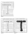
- drop placement and drop formation diagrams are illustrated for a letter "T", with orifices labeled as rows 1 through 10, and paper motion indicated by columns A through J (excluding I).
- Each square, indicated by a row number and a column letter, is termed a pixel.
- error deflection can be to the right or to the left of the desired pixel or print location.
- Fig. 1 there is illustrated ideal drop placement for the letter T, with the resulting drop formation shown in Fig. 2.
- actual drop placement is dependent on a number of factors, including partial charging by adjacent jets. Therefore, all lateral neighbors of drops B2, C2, D2, F2, G2, and H2 have been fully charged, so that those drops receive a partial charge.
- the partial charge causes those drops to be deflected to some degree before the drops reach the print media. The amount of deflection is dependent upon several factors, such as charge voltage, print head configuration, and print distance.
- Fig. 3 the actual drop placement, because of the print conditions, shows error deflection of approximately one full pixel to the right, as compared to the desired drop placement illustrated in Fig. 1. Since drops E4, E5, E6 and E7 are adjacent to print drops, with very little, if any, charge, those drops will print near the locations where intended. Drops E2 and E9 have fully charged drops on one side, i.e., drops E1 and E10, respectively, drops E2 and E9 will nominally have a location error of approximately half as much as drops B2, C2, D2, F2, G2, and H2, causing drops E2 and E9 to print approximately on the boundary between pixel locations E and F. Drops E3 and E8 receive some charging from proximate drops E1 and E10, with the resulting error placement being less than 1/4 pixel. The resulting character formation due to the print errors is illustrated in Fig. 4.
- Drops bounded by fully charged drops will have a partial charge. Drops bounded by two print drops on each side, or four print drops, will have very little or no charge. A print drop with any of its four neighbors fully charged will receive some partial charge.
- Print errors are more noticeable for small characters with thin strokes, whereas the errors are not as great nor as visible for larger characters with thicker strokes.
- the defects tend to be consistent throughout a particular set of smaller characters, and often become an acceptable part of the character set style appearance.
- OCR optical character recognition
- Fig. 9 meets those requirements. Because every drop is surrounded by fully charged drops, drop placement errors are nearly the same for each print drop, as seen in Fig. 8. That is, every print drop is deflected to the right by nearly one full pixel.
- Figs. 5-7 The character bit map is shown in Fig. 5, with the expected drop placements shown in Fig. 6. Most of the drops in row 2 are deflected a full pixel, except drop 2E is deflected by less than a half pixel because most of its adjacent neighbor drops have not been charged. Drop 9D deflects nearly a full pixel, drop 9E only half a pixel, drop 8E about 1/4th of a pixel, and drops E4-7 not at all.
- print quality for an ink jet printer is improved by selecting one or more print drops for printing, and subjecting each of the chosen print drops to an approximately equal amount of partial charging.
- the drops are selected by determining which potential print drops will print at desired locations on the print media.
- the print drops are subjected to an equal amount of partial charging by selectively creating one or more guard drops between the print drops in a row and one or more guard drops between the print drops in a column. This, then, reduces print error.
- the present invention is particularly applicable to an ink jet printing apparatus which includes a print head for generating a plurality of continuous ink jets, arranged in a row and directed toward a print receiving medium.
- the print head typically includes means for synchronously stimulating the ink jets to produce a rectangular array of ink drops, with the array having columns corresponding to the consecutive drops in a single jet, and rows corresponding to drops simultaneously produced from all of the jets.
- Print drops and partially charged drops are printed on a print media and fully charged drops are deflected from the print media.
- the print head further includes a plurality of drop charging electrodes positioned adjacent the row of ink jets.
- the ink jet printing apparatus further includes means for selecting one or more print drops for printing, and means for subjecting each of the chosen print drops to an equal amount of partial charging.
- the approach of the present invention of anticipating drop placement has more flexibility when the printer is operated in a printing mode using double resolution (dots/inch) across the character pattern, i.e., the direction of paper travel. That is, the numbered jets remain at a particular resolution (120 dots per inch, for example) and the drops (identified by letters) can be at 240 dots per inch.
- OCR Optical Character Recognition
- the present invention is useful in the field of ink jet printing, and has the advantage of improving the appearance of character patterns, particularly in high speed ink jet printers.
Landscapes
- Particle Formation And Scattering Control In Inkjet Printers (AREA)
Abstract
Description
- The present invention relates to ink jet printers and, more particularly, to improved character pattern designs for high speed ink jet printers.
- In a continuous multi-jet ink jet printer, ink is supplied under pressure to a manifold region that distributes the ink to a plurality of orifices, typically arranged in a linear array(s). The ink discharges from the orifices in filaments which break into droplet streams. The row of continuous ink jets that are stimulated produce a two-dimensional array of ink drops that are directed to a print receiving medium. The approach for printing with these droplet streams is to selectively charge and deflect certain drops from their normal trajectories.
- In systems in which printing is accomplished with uncharged drops, it is important that the print drops do not receive a slight charge inadvertently. One source of inadvertent charging is the drops which have previously formed in the stream. Assuming the previous drop in a stream carries a charge, the subsequent uncharged drop will be formed in sufficient proximity to the charged drop that a slight charge of opposite polarity may be induced. Such drop-to-drop interference has been recognized as a significant problem, and has been treated in several patents.
- In a system in which the jets are positioned relatively close together to increase the system resolution, a charge may be induced in a drop by a charging electrode associated with an adjacent jet. This problem is known as crosstalk, and adversely affects print quality. The effect of an unintentional charge so induced upon a charged drop, which is to be caught, is merely to alter its deflected trajectory slightly. The catching arrangement is such that the drop will still be caught. However, a print drop which is inadvertently charged by an adjacent charge electrode will be slightly deflected into a trajectory which will significantly affect the printing quality of the system. As the print distances increases, to about 0.7" from the bottom of the catcher, serious print defects exist. The defects consist of curved vertical segments and spaces between vertical and horizontal segments.
- In high resolution ink jet printers, two types of charging inaccuracies can occur. One type, called drop-to-drop crosstalk, results from the influence of previously charged drops on subsequent drops in a single ink jet. The other type, called jet-to-jet crosstalk, results from the influence of the charge on neighboring electrodes. These two types of charging inaccuracies cause variations in drop placement on the print receiving medium, and hence a deterioration in the characters formed by the ink jet printer.
- One approach to solving this crosstalk problem is described in U.S. Patent No. 4,613,871, issued September 23, 1986, to J. Katerberg. According to this approach, a repeating pattern of guard drops, charged to a catch potential, are provided to isolate the print drops from the influence of other print drops. In particular, one or more rows have all guard drops.
- In order to meet speed requirements for high speed ink jet printers, it is desirable to be able to print with every drop from the array of jets. However, this means that there are no guard drops, so the deflection field would be minimal. When character patterns are used in high speed printing that permit selection of every drop in both the vertical, along the array, and the horizontal, in the direction of substrate motion, axes, the result is a deterioration in character quality. For example, characters contain too much ink, with slow drying, offset, misting or splashing of overlapping drops, and smear.
- It is therefore the object of the present invention to provide a method and apparatus for improving character pattern designs for high speed ink jet printers which overcome the problems and disadvantages of prior procedures.
- The object of the present invention is achieved by providing a high speed printing pattern for a continuous ink jet array that employs drops from adjacent jets but does not allow consecutive drops from a single jet. Hence, the print head is driven with an inhibit function that prevents consecutive drops from a single jet or guard drops in the direction of the substrate, or copy receptor motion.
- In accordance with one aspect of the present invention, a method is provided for improving print quality in a continuous multi-jet ink jet printer of the type including means for producing a rectangular array of ink drops, the array having columns corresponding to the consecutive drops in a single jet, and rows corresponding to drops simultaneously produced from all of the jets, where print drops and partially charged drops are printed on a print media and fully charged drops are deflected from the print media. The method includes the steps of selecting one or more print drops for printing, and subjecting each of the one or more print drops to an approximately equal amount of partial charging.
- Other objects and advantages of the invention will be apparent from the following description, the accompanying drawings and the appended claims.
- The following figures illustrate drop placement and drop formation for varying print conditions.
- Fig. 1 illustrates perfect drop placement;
- Fig. 2 illustrates the resulting drop formation given the drop placement of Fig. 1;
- Fig. 3 illustrates actual drop placement, due to print conditions;
- Fig. 4 illustrates the resulting drop formation given the drop placement of Fig. 3;
- Fig. 5 illustrates knowledge of expected drop deflection as applied to character design;
- Fig. 6 illustrates the expected drop placements given the expected drop deflection of Fig. 5;
- Fig. 7 illustrates the resulting drop formation given the expected drop deflection and expected drop placement of Figs. 5 and 6;
- Fig. 8 illustrates drop placement when all drops are equally deflected;
- Fig. 9 illustrates the resulting drop formation given the drop placement of Fig. 8; and
- Figs. 10 and 11 show drop placement and drop formation for bolder stroke printing.
- In continuous multi-jet ink jet printers, ink is discharged from orifices in filaments which break into droplet streams. The row of continuous ink jets produce a two-dimensional array of ink drops that are directed to a print receiving medium. Depending on the print conditions, i.e., the position of the printhead and the direction of movement of the print media, error deflection can be to the right or to the left of the desired print location. To correct for this error deflection, the present invention provides an inhibit function that prevents consecutive drops from a single jet or guard drops in the direction of the substrate or copy receptor motion. That is, in accordance with the present invention, a high speed printing pattern for a continuous ink jet array employs drops from adjacent jets but does not allow consecutive drops from a single jet.
- Referring now to the drawings, drop placement and drop formation diagrams are illustrated for a letter "T", with orifices labeled as
rows 1 through 10, and paper motion indicated by columns A through J (excluding I). Each square, indicated by a row number and a column letter, is termed a pixel. As stated, depending on the position of the printhead and the direction of movement of the print media, error deflection can be to the right or to the left of the desired pixel or print location. - In Fig. 1 there is illustrated ideal drop placement for the letter T, with the resulting drop formation shown in Fig. 2. However, actual drop placement is dependent on a number of factors, including partial charging by adjacent jets. Therefore, all lateral neighbors of drops B2, C2, D2, F2, G2, and H2 have been fully charged, so that those drops receive a partial charge. The partial charge causes those drops to be deflected to some degree before the drops reach the print media. The amount of deflection is dependent upon several factors, such as charge voltage, print head configuration, and print distance.
- Referring now to Fig. 3, the actual drop placement, because of the print conditions, shows error deflection of approximately one full pixel to the right, as compared to the desired drop placement illustrated in Fig. 1. Since drops E4, E5, E6 and E7 are adjacent to print drops, with very little, if any, charge, those drops will print near the locations where intended. Drops E2 and E9 have fully charged drops on one side, i.e., drops E1 and E10, respectively, drops E2 and E9 will nominally have a location error of approximately half as much as drops B2, C2, D2, F2, G2, and H2, causing drops E2 and E9 to print approximately on the boundary between pixel locations E and F. Drops E3 and E8 receive some charging from proximate drops E1 and E10, with the resulting error placement being less than 1/4 pixel. The resulting character formation due to the print errors is illustrated in Fig. 4.
- Drops bounded by fully charged drops will have a partial charge. Drops bounded by two print drops on each side, or four print drops, will have very little or no charge. A print drop with any of its four neighbors fully charged will receive some partial charge.
- Print errors are more noticeable for small characters with thin strokes, whereas the errors are not as great nor as visible for larger characters with thicker strokes. In addition, the defects tend to be consistent throughout a particular set of smaller characters, and often become an acceptable part of the character set style appearance. However, for the smaller character patterns, and especially for optical character recognition (OCR) equipment, the defects are objectionable, and the print errors have to be resolved for varying print conditions.
- For instance, in some printer applications, speed and fast drying, i.e., low amounts of ink, are more important. The character design of Fig. 9 meets those requirements. Because every drop is surrounded by fully charged drops, drop placement errors are nearly the same for each print drop, as seen in Fig. 8. That is, every print drop is deflected to the right by nearly one full pixel.
- In other applications, bolder characters are desired, with satisfactory results shown in Figs. 10 and 11. However, in this case, the drops in the vertical stroke are not deflected as much as the horizontal stroke of the T. Nevertheless, the printed results of Fig. 11 are satisfactory and drying is very good.
- To meet the scannability of OCR, the knowledge of expected drop deflection is applied to character design, as illustrated in Figs. 5-7. The character bit map is shown in Fig. 5, with the expected drop placements shown in Fig. 6. Most of the drops in
row 2 are deflected a full pixel, except drop 2E is deflected by less than a half pixel because most of its adjacent neighbor drops have not been charged. Drop 9D deflects nearly a full pixel, drop 9E only half a pixel, drop 8E about 1/4th of a pixel, and drops E4-7 not at all. - In the present invention, print quality for an ink jet printer is improved by selecting one or more print drops for printing, and subjecting each of the chosen print drops to an approximately equal amount of partial charging. The drops are selected by determining which potential print drops will print at desired locations on the print media. The print drops are subjected to an equal amount of partial charging by selectively creating one or more guard drops between the print drops in a row and one or more guard drops between the print drops in a column. This, then, reduces print error.
- The present invention is particularly applicable to an ink jet printing apparatus which includes a print head for generating a plurality of continuous ink jets, arranged in a row and directed toward a print receiving medium. The print head typically includes means for synchronously stimulating the ink jets to produce a rectangular array of ink drops, with the array having columns corresponding to the consecutive drops in a single jet, and rows corresponding to drops simultaneously produced from all of the jets. Print drops and partially charged drops are printed on a print media and fully charged drops are deflected from the print media. The print head further includes a plurality of drop charging electrodes positioned adjacent the row of ink jets. The ink jet printing apparatus further includes means for selecting one or more print drops for printing, and means for subjecting each of the chosen print drops to an equal amount of partial charging.
- The approach of the present invention of anticipating drop placement has more flexibility when the printer is operated in a printing mode using double resolution (dots/inch) across the character pattern, i.e., the direction of paper travel. That is, the numbered jets remain at a particular resolution (120 dots per inch, for example) and the drops (identified by letters) can be at 240 dots per inch. The approach illustrated in Fig. 5 has been applied to designing Optical Character Recognition (OCR) sets A & B bit maps with the printed results being very well recognized by OCR scanners.
- The present invention is useful in the field of ink jet printing, and has the advantage of improving the appearance of character patterns, particularly in high speed ink jet printers.
- The invention has been described in detail with particular reference to certain preferred embodiments thereof, but it will be understood that modifications and variations can be effected within the spirit and scope of the invention.
Claims (6)
- A method for improving print quality in a continuous multi-jet ink jet printer of the type including means for producing a rectangular array of ink drops, the array having columns corresponding to the consecutive drops in a single jet, and rows corresponding to drops simultaneously produced from all of the jets, where print drops and partially charged drops are printed on a print media and fully charged drops are deflected from the print media, the method including the steps of:a. selecting one or more print drops for printing; andb. subjecting each of the one or more print drops to an approximately equal amount of partial charging.
- A method for improving print quality as claimed in claim 1 wherein the step of selecting one or more print drops for printing comprises the step of determining which potential print drops will print at desired locations on the print media.
- A method for improving print quality as claimed in claim 1 wherein the step of subjecting each of the one or more print drops to an equal amount of partial charging comprises the step of selectively creating one or more guard drops between the print drops in a row and one or more guard drops between the print drops in a column to reduce print error.
- Ink jet printing apparatus comprising:a. a print head for generating a plurality of continuous ink jets, arranged in a row and directed toward a print receiving medium, the print head including,(1) means for synchronously stimulating the ink jets to produce a rectangular array of ink drops, the array having columns corresponding to the consecutive drops in a single jet, and rows corresponding to drops simultaneously produced from all of the jets, where print drops and partially charged drops are printed on a print media and fully charged drops are deflected from the print media, and(2) a plurality of drop charging electrodes positioned adjacent the row of ink jets;b. means for selecting one or more print drops for printing; andc. means for subjecting each of the one or more print drops to an equal amount of partial charging.
- The ink jet printing apparatus claimed in claim 4 wherein the means for selecting one or more print drops for printing comprises means for determining which potential print drops will print at desired locations on the print media.
- The ink jet printing apparatus claimed in claim 4 wherein the means for subjecting each of the one or more print drops to an equal amount of partial charging comprises means for selectively creating one or more guard drops between the print drops in a row and one or more guard drops between the print drops in a column to reduce print error.
Applications Claiming Priority (2)
| Application Number | Priority Date | Filing Date | Title |
|---|---|---|---|
| US10793493A | 1993-08-17 | 1993-08-17 | |
| US107934 | 1993-08-17 |
Publications (2)
| Publication Number | Publication Date |
|---|---|
| EP0639459A2 true EP0639459A2 (en) | 1995-02-22 |
| EP0639459A3 EP0639459A3 (en) | 1996-10-16 |
Family
ID=22319264
Family Applications (1)
| Application Number | Title | Priority Date | Filing Date |
|---|---|---|---|
| EP94305480A Withdrawn EP0639459A3 (en) | 1993-08-17 | 1994-07-25 | Method and apparatus for operating high speed ink jet printers. |
Country Status (1)
| Country | Link |
|---|---|
| EP (1) | EP0639459A3 (en) |
Cited By (6)
| Publication number | Priority date | Publication date | Assignee | Title |
|---|---|---|---|---|
| EP0891009A3 (en) * | 1997-06-24 | 2000-03-29 | Shimano Inc. | Flat cable connector for a bicycle |
| EP1316429A1 (en) * | 1998-09-03 | 2003-06-04 | Videojet Technologies Inc. | An Ink Jet Printing System |
| US7943813B2 (en) | 2002-12-30 | 2011-05-17 | Kimberly-Clark Worldwide, Inc. | Absorbent products with enhanced rewet, intake, and stain masking performance |
| US8273066B2 (en) | 2003-07-18 | 2012-09-25 | Kimberly-Clark Worldwide, Inc. | Absorbent article with high quality ink jet image produced at line speed |
| JP2022112570A (en) * | 2021-01-22 | 2022-08-03 | 紀州技研工業株式会社 | Ink jet printer |
| CN115157658A (en) * | 2022-06-23 | 2022-10-11 | 浙江大学 | Method for preparing binary coding droplet array by microfluidic 3D droplet printing |
Citations (5)
| Publication number | Priority date | Publication date | Assignee | Title |
|---|---|---|---|---|
| US4364058A (en) * | 1979-10-29 | 1982-12-14 | Fuji Xerox Co., Ltd. | Ink drop charging device |
| US4490729A (en) * | 1982-09-15 | 1984-12-25 | The Mead Corporation | Ink jet printer |
| US4555710A (en) * | 1981-12-20 | 1985-11-26 | Ricoh Company, Ltd. | Charge-controlled ink-jet printing method and apparatus |
| US4613871A (en) * | 1985-11-12 | 1986-09-23 | Eastman Kodak Company | Guard drops in an ink jet printer |
| EP0206614A1 (en) * | 1985-06-11 | 1986-12-30 | Domino Printing Sciences Plc | Continuous ink jet printing |
-
1994
- 1994-07-25 EP EP94305480A patent/EP0639459A3/en not_active Withdrawn
Patent Citations (5)
| Publication number | Priority date | Publication date | Assignee | Title |
|---|---|---|---|---|
| US4364058A (en) * | 1979-10-29 | 1982-12-14 | Fuji Xerox Co., Ltd. | Ink drop charging device |
| US4555710A (en) * | 1981-12-20 | 1985-11-26 | Ricoh Company, Ltd. | Charge-controlled ink-jet printing method and apparatus |
| US4490729A (en) * | 1982-09-15 | 1984-12-25 | The Mead Corporation | Ink jet printer |
| EP0206614A1 (en) * | 1985-06-11 | 1986-12-30 | Domino Printing Sciences Plc | Continuous ink jet printing |
| US4613871A (en) * | 1985-11-12 | 1986-09-23 | Eastman Kodak Company | Guard drops in an ink jet printer |
Cited By (10)
| Publication number | Priority date | Publication date | Assignee | Title |
|---|---|---|---|---|
| EP0891009A3 (en) * | 1997-06-24 | 2000-03-29 | Shimano Inc. | Flat cable connector for a bicycle |
| US6129580A (en) * | 1997-06-24 | 2000-10-10 | Shimano, Inc. | Flat bicycle cable connector |
| EP1316429A1 (en) * | 1998-09-03 | 2003-06-04 | Videojet Technologies Inc. | An Ink Jet Printing System |
| US7943813B2 (en) | 2002-12-30 | 2011-05-17 | Kimberly-Clark Worldwide, Inc. | Absorbent products with enhanced rewet, intake, and stain masking performance |
| US8273066B2 (en) | 2003-07-18 | 2012-09-25 | Kimberly-Clark Worldwide, Inc. | Absorbent article with high quality ink jet image produced at line speed |
| US9006509B2 (en) | 2003-07-18 | 2015-04-14 | Kimberly-Clark Worldwide, Inc. | Absorbent article with high quality ink jet image produced at line speed |
| US9901492B2 (en) | 2003-07-18 | 2018-02-27 | Kimberly-Clark Worldwide, Inc. | Absorbent article with high quality ink jet image produced at line speed |
| JP2022112570A (en) * | 2021-01-22 | 2022-08-03 | 紀州技研工業株式会社 | Ink jet printer |
| CN115157658A (en) * | 2022-06-23 | 2022-10-11 | 浙江大学 | Method for preparing binary coding droplet array by microfluidic 3D droplet printing |
| CN115157658B (en) * | 2022-06-23 | 2023-11-24 | 浙江大学 | Method for preparing binary coded droplet array by microfluidic 3D droplet printing |
Also Published As
| Publication number | Publication date |
|---|---|
| EP0639459A3 (en) | 1996-10-16 |
Similar Documents
| Publication | Publication Date | Title |
|---|---|---|
| US5258774A (en) | Compensation for aerodynamic influences in ink jet apparatuses having ink jet chambers utilizing a plurality of orifices | |
| US4613871A (en) | Guard drops in an ink jet printer | |
| CA1204960A (en) | Ink jet printer | |
| US4091390A (en) | Arrangement for multi-orifice ink jet print head | |
| US3938163A (en) | Printed pattern inclination control in ink jet printer | |
| EP0865927B1 (en) | Printing apparatus and printing method using multiple nozzle groups | |
| US4596990A (en) | Multi-jet single head ink jet printer | |
| EP0034060A1 (en) | Ink jet printer | |
| US4504839A (en) | Deflecting electrode assembly for multi-nozzle ink jets | |
| US7438396B2 (en) | Inkjet printing method and apparatus | |
| US6157461A (en) | Method of generating randomized masks to improve image quality on a printing medium | |
| EP0639459A2 (en) | Method and apparatus for operating high speed ink jet printers | |
| US4380017A (en) | Method for ink jet printing | |
| CA1097720A (en) | Ink jet nozzle arrangement | |
| US4525721A (en) | Ink jet interlace strategy | |
| EP1109673B1 (en) | Improved dot positioning for continuous ink jet printer | |
| US4520368A (en) | Ink jet printing method and apparatus | |
| EP1126977B1 (en) | Ink jet printing system | |
| US5801734A (en) | Two row flat face charging for high resolution printing | |
| EP0084891B1 (en) | A multi-jet single head ink jet printer | |
| US6003979A (en) | Gray scale printing with high resolution array ink jet | |
| US6595629B2 (en) | Continuous inkjet printer | |
| US6527375B2 (en) | Ink jet recording device capable of controlling impact positions of ink droplets | |
| US6454391B1 (en) | Multi-nozzle ink jet recording device including common electrodes for generating deflector electric field | |
| US4429315A (en) | Multi-nozzle ink jet printer |
Legal Events
| Date | Code | Title | Description |
|---|---|---|---|
| PUAI | Public reference made under article 153(3) epc to a published international application that has entered the european phase |
Free format text: ORIGINAL CODE: 0009012 |
|
| AK | Designated contracting states |
Kind code of ref document: A2 Designated state(s): DE FR GB |
|
| PUAL | Search report despatched |
Free format text: ORIGINAL CODE: 0009013 |
|
| AK | Designated contracting states |
Kind code of ref document: A3 Designated state(s): DE FR GB |
|
| 17P | Request for examination filed |
Effective date: 19961125 |
|
| 17Q | First examination report despatched |
Effective date: 19980309 |
|
| STAA | Information on the status of an ep patent application or granted ep patent |
Free format text: STATUS: THE APPLICATION IS DEEMED TO BE WITHDRAWN |
|
| 18D | Application deemed to be withdrawn |
Effective date: 19980922 |