EP0638324A1 - Luer needle unit and injector - Google Patents
Luer needle unit and injector Download PDFInfo
- Publication number
- EP0638324A1 EP0638324A1 EP94112273A EP94112273A EP0638324A1 EP 0638324 A1 EP0638324 A1 EP 0638324A1 EP 94112273 A EP94112273 A EP 94112273A EP 94112273 A EP94112273 A EP 94112273A EP 0638324 A1 EP0638324 A1 EP 0638324A1
- Authority
- EP
- European Patent Office
- Prior art keywords
- needle
- syringe
- luer
- luer needle
- cap
- Prior art date
- Legal status (The legal status is an assumption and is not a legal conclusion. Google has not performed a legal analysis and makes no representation as to the accuracy of the status listed.)
- Granted
Links
Images


Classifications
-
- A—HUMAN NECESSITIES
- A61—MEDICAL OR VETERINARY SCIENCE; HYGIENE
- A61M—DEVICES FOR INTRODUCING MEDIA INTO, OR ONTO, THE BODY; DEVICES FOR TRANSDUCING BODY MEDIA OR FOR TAKING MEDIA FROM THE BODY; DEVICES FOR PRODUCING OR ENDING SLEEP OR STUPOR
- A61M5/00—Devices for bringing media into the body in a subcutaneous, intra-vascular or intramuscular way; Accessories therefor, e.g. filling or cleaning devices, arm-rests
- A61M5/178—Syringes
- A61M5/31—Details
- A61M5/32—Needles; Details of needles pertaining to their connection with syringe or hub; Accessories for bringing the needle into, or holding the needle on, the body; Devices for protection of needles
-
- A—HUMAN NECESSITIES
- A61—MEDICAL OR VETERINARY SCIENCE; HYGIENE
- A61M—DEVICES FOR INTRODUCING MEDIA INTO, OR ONTO, THE BODY; DEVICES FOR TRANSDUCING BODY MEDIA OR FOR TAKING MEDIA FROM THE BODY; DEVICES FOR PRODUCING OR ENDING SLEEP OR STUPOR
- A61M5/00—Devices for bringing media into the body in a subcutaneous, intra-vascular or intramuscular way; Accessories therefor, e.g. filling or cleaning devices, arm-rests
- A61M5/178—Syringes
- A61M5/28—Syringe ampoules or carpules, i.e. ampoules or carpules provided with a needle
- A61M5/285—Syringe ampoules or carpules, i.e. ampoules or carpules provided with a needle with sealing means to be broken or opened
- A61M5/288—Syringe ampoules or carpules, i.e. ampoules or carpules provided with a needle with sealing means to be broken or opened by piercing without internal pressure increase
-
- A—HUMAN NECESSITIES
- A61—MEDICAL OR VETERINARY SCIENCE; HYGIENE
- A61M—DEVICES FOR INTRODUCING MEDIA INTO, OR ONTO, THE BODY; DEVICES FOR TRANSDUCING BODY MEDIA OR FOR TAKING MEDIA FROM THE BODY; DEVICES FOR PRODUCING OR ENDING SLEEP OR STUPOR
- A61M5/00—Devices for bringing media into the body in a subcutaneous, intra-vascular or intramuscular way; Accessories therefor, e.g. filling or cleaning devices, arm-rests
- A61M5/178—Syringes
- A61M5/31—Details
- A61M5/32—Needles; Details of needles pertaining to their connection with syringe or hub; Accessories for bringing the needle into, or holding the needle on, the body; Devices for protection of needles
- A61M5/34—Constructions for connecting the needle, e.g. to syringe nozzle or needle hub
- A61M5/344—Constructions for connecting the needle, e.g. to syringe nozzle or needle hub using additional parts, e.g. clamping rings or collets
-
- Y—GENERAL TAGGING OF NEW TECHNOLOGICAL DEVELOPMENTS; GENERAL TAGGING OF CROSS-SECTIONAL TECHNOLOGIES SPANNING OVER SEVERAL SECTIONS OF THE IPC; TECHNICAL SUBJECTS COVERED BY FORMER USPC CROSS-REFERENCE ART COLLECTIONS [XRACs] AND DIGESTS
- Y10—TECHNICAL SUBJECTS COVERED BY FORMER USPC
- Y10S—TECHNICAL SUBJECTS COVERED BY FORMER USPC CROSS-REFERENCE ART COLLECTIONS [XRACs] AND DIGESTS
- Y10S604/00—Surgery
- Y10S604/905—Aseptic connectors or couplings, e.g. frangible, piercable
Landscapes
- Health & Medical Sciences (AREA)
- Animal Behavior & Ethology (AREA)
- Life Sciences & Earth Sciences (AREA)
- Anesthesiology (AREA)
- Biomedical Technology (AREA)
- General Health & Medical Sciences (AREA)
- Hematology (AREA)
- Engineering & Computer Science (AREA)
- Vascular Medicine (AREA)
- Heart & Thoracic Surgery (AREA)
- Public Health (AREA)
- Veterinary Medicine (AREA)
- Infusion, Injection, And Reservoir Apparatuses (AREA)
- Pharmaceuticals Containing Other Organic And Inorganic Compounds (AREA)
- Medicines That Contain Protein Lipid Enzymes And Other Medicines (AREA)
- Radiation-Therapy Devices (AREA)
- Accommodation For Nursing Or Treatment Tables (AREA)
Abstract
Description
- The present invention generally relates to a luer needle unit and an injector for medical use, and more particularly to a luer needle unit used along with a prefilled syringe, that is, a syringe having pharmaceutical liquid preliminarily filled therein and which allows setting of a disposable needle thereto, and an injector using the luer needle unit.
- An injector of the aforementioned type has been constructed in various kinds of structure. For example, in an injector disclosed in Japanese Utility Model Laid-Open Publication No. 2-96149 (96149/1990), a luer needle is preliminarily set to a supporting cap for supporting it fitted at a mouth of a prefilled syringe. While a needle part of the luer needle is held not to penetrate a sealing cap of the syringe before the use, a disposable needle is fixed at the outside of the luer needle and pressed together with the luer needle to the syringe at the using time, whereby the needle part pierces the sealing cap to allow the pharmaceutical liquid in the syringe to flow out through the needle part.
- In the constitution as above, since it is necessary to rotate and pull out the disposable needle from the syringe after the use in order to dispose of the disposable needle, in some cases, the luer needle alike is rotated and inadvertently taken out concurrently with the disposable needle. The needle part of the pulled out luer needle may hurt fingers or the like of a user. Moreover, at the setting time of the luer needle to the supporting cap after the supporting cap is fitted at the mouth of the syringe, it may undesirably take place that the needle part of the luer needle pierces the supporting cap due to the absence of a guiding member for the needle part. Therefore, it has been difficult to set the luer needle to the supporting cap.
- Accordingly, an object of the present invention is to provide a luer needle unit and an injector effectively preventing a user's fingers from being hurt when a disposable needle is to be detached from a luer needle after the use while allowing simple and positive mounting of the luer needle to a supporting cap.
- In accomplishing this and other objects, according to one aspect of the present invention, there is provided a luer needle unit comprising:
a luer needle supporting cap to be fitted at a mouth of a syringe having pharmaceutical liquid filled therein beforehand, and
a luer needle having one needle part which is selectively held in engagement with the supporting cap at a non-use position where the needle part does not pierce a syringe cap provided at the mouth of the syringe and at a use position where the needle part pierces the syringe cap and, to which a disposable needle is setable,
wherein the supporting cap has a flange portion, a cylindrical guiding projecting portion extending at one side of the flange portion and having a through hole through which the needle part is penetrable, and a cylindrical portion extending at the other side of the flange portion to be fitted in the mouth of the syringe, so that a fitting portion of the luer needle is fitted outside the guiding projecting portion due to guidance of the guiding projecting portion,
guide protrusions extend in an axial direction of the syringe at one of confronting surfaces of the supporting cap and luer needle, which are engaged with guide recesses formed at the other of the confronting surfaces of the supporting cap and the luer needle in the axial direction of the syringe, thereby to prohibit relative rotation of the luer needle and the supporting cap and to guide engagement of the luer needle with the supporting cap in the axial direction of the syringe, and
a distance at the two positions of the luer needle to the supporting cap is not smaller than a sum of an axial distance between a front end and a base end of a notch portion of the needle part of the luer needle and a thickness of the syringe cap. - According to another aspect of the present invention, there is provided an injector equipped with a luer needle unit comprising:
a luer needle supporting cap to be fitted at a mouth of a syringe having pharmaceutical liquid filled therein beforehand, and
a luer needle having one needle part which is selectively held in engagement with the supporting cap at a non-use position where the needle part does not pierce a syringe cap provided at the mouth of the syringe and at a use position where the needle part pierces the syringe cap and, to which a disposable needle is setable,
wherein the supporting cap has a flange portion, a cylindrical guiding projecting portion extending at one side of the flange portion and having a through hole through which the needle part is penetrable, and a cylindrical portion extending at the other side of the flange portion to be fitted in the mouth of the syringe, so that a fitting portion of the luer needle is fitted outside the guiding projecting portion due to guidance of the guiding projecting portion,
guide protrusions extend in an axial direction of the syringe at one of confronting surfaces of the supporting cap and luer needle, which are engaged with guide recesses formed at the other of the confronting surfaces of the supporting cap and the luer needle in the axial direction of the syringe, thereby to prohibit relative rotation of the luer needle and the supporting cap and to guide engagement of the luer needle with the supporting cap in the axial direction of the syringe, and
a distance at the two positions of the luer needle to the supporting cap is not smaller than a sum of an axial distance between a front end and a base end of a notch portion of the needle part of the luer needle and a thickness of the syringe cap. - These and other objects and features of the present invention will become clear from the following description taken in conjunction with the preferred embodiments thereof with reference to the accompanying drawings, in which:
- Fig. 1 is a sectional view of a part of an injector with a luer needle unit in one embodiment of the present invention;
- Fig. 2 is an exploded perspective view of the luer needle unit of Fig. 1;
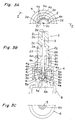
- Figs. 3A, 3B and 3C are a plane view of the upper half of the luer needle unit before the injector is used, a sectional view of the injector taken along a line II-II of Fig. 3A, and a bottom view of the lower half of the injector, respectively;
- Figs. 4A, 4B and 4C are a plan view of the upper half of the luer needle unit when the injector is used, a sectional view of the injector taken along a line III-III of Fig. 3A, and a bottom view of the lower half of the injector, respectively;
- Fig. 5 is an enlarged view of a front end of a needle;
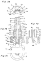
- Fig. 6 is an exploded perspective view of a luer needle unit in another embodiment of the present invention; and
- Figs. 7A, 7B, 7C, and 7D are a plan view of the upper half of the luer needle unit of Fig. 6 before an injector is used, a sectional view of the injector of the luer needle unit, a bottom view of the lower half of the injector, and a sectional view of a supporting cap respectively.
- Before the description of the present invention proceeds, it is to be noted that like parts are designated by like reference numerals throughout the accompanying drawings.
- A preferred embodiment of the present invention will be described in detail with reference to Figs. 1-7.
- As shown in Fig. 1, an injector according to the embodiment has a
syringe cap 5 provided at amouth 6a of asyringe 6 in which pharmaceutical liquid is already filled. Aneedle part 3 of aluer needle 2 is penetrable through thesyringe cap 5. A luerneedle supporting cap 4 is set at themouth 6a so that theluer needle 2 can be held in engagement with the supportingcap 4 at two positions, that is, a non-use position where afront notch portion 3a of theneedle part 3 of theluer needle 2 does not pierce thesyringe cap 5 and a use position where thefront notch portion 3a penetrates thesyringe cap 5. At the same time, a disposable needle 1 can be set to theluer needle 2. The luer needle unit is thus composed of the supportingcap 4 and theluer needle 2. - The disposable needle 1 has a needle
main body 1a and a generallycylindrical fitting part 1b which supports the needlemain body 1a and can be fitted into the outer periphery of theluer needle 2. Thefitting part 1b is desirably formed of transparent material so that a blood vessel is confirmed at a hollow 1c between theluer needle 2 and themain body 1a. - As shown in Figs. 1-3, the
mouth 6a of thesyringe 6 is so constructed that an inner surface of athrough hole 6b and an outer end face of themouth 6a are kept in tight contact with thesyringe cap 5 made of elastic material such as rubber or the like. Pharmaceutical liquid is sealed in thesyringe 6. Thesyringe cap 5 has aflange portion 5b able to be tightly held in touch with the outer end face of themouth 6a and, a cylindrical leg portion 5a extended from theflange portion 5b and tightly fitted in aninner recess 6b of themouth 6a. A front end of theneedle part 3 of theluer needle 2 is accommodated in aninner fitting recess 5d of the leg portion 5a as will be described later. Theneedle part 3 pierces abottom 5e of the inner fitting recess 5d when the injector is used. - The supporting
cap 4 is generally an integral body of two, large and smallcylindrical portions flange portion 4f. More specifically, referring to Figs. 1-3, the lowercylindrical portion 4a of a larger diameter projecting downward from theflange portion 4f has an engaging projection 4i at the inner peripheral face at the lower end thereof. The supportingcap 4 is accordingly securely fitted at the outer peripheral part of themouth 6a of thesyringe 6, and prevented from slipping off from themouth 6a. Anannular protrusion 4j like a wedge in section is formed at the lower inner face of theflange portion 4f. When the engaging projection 4i is fitted at thesyringe mouth 6a, theannular protrusion 4j is pressed in the upper surface of thesyringe cap 5 thereby to enhance the contact between thesyringe mouth 6a and thesyringe cap 5. Acylindrical guide portion 4d of a small diameter is extended downward from the central part of the lower face of theflange portion 4f inside the lowercylindrical portion 4a, which is fitted into theinner recess 5d of thesyringe cap 5 to smoothly guide theneedle part 3 of theluer needle 2 in the axial direction along a needle throughhole 4e thereinside. The provision of thecylindrical guide portion 4d is not necessarily required if it is not necessary to guide theneedle part 3 in the axial direction. The uppercylindrical portion 4b of a smaller diameter than that of the lowercylindrical portion 4a projects at the upper side of theflange portion 4f which is an upper end face of the lowercylindrical portion 4a. Further, a guiding projectingportion 4g projects upward from the central part at the upper face of theflange portion 4f so as to guide theluer needle 2 in the axial direction when theluer needle 2 is fitted into the supportingcap 4, as will be described later. A throughhole 4c formed at the central part of the guiding projectingportion 4g serves to guide theluer needle part 3 smoothly. As indicated in Fig. 3A, there are also provided eight rectangular, curved guidingrecesses 4k, ..., 4k in the inner peripheral face of the uppercylindrical portion 4b. The guidingrecesses 4k are separated an equal distance in the circumferential direction and elongated in the axial direction of the uppercylindrical portion 4b. An annularengaging protrusion 4m in the shape of a projecting wedge in section extends at the inner peripheral face of the upper end of the uppercylindrical portion 4b in the circumferential direction orthogonal to the axial direction of thesyringe 6. - Meanwhile, the
luer needle 2 has a throughhole 2a at the upper face of amain body 2j. The throughhole 2a is smaller in diameter than theneedle part 3. Moreover, theluer needle 2 has afitting recess 2b continuous with the throughhole 2a. As theneedle part 3 is fitted and bonded into thefitting recess 2b, theluer needle 2 is fixed to be unable to move in the axial direction. Since the diameter of the throughhole 2a is made smaller than that of theneedle part 3, theneedle part 3 is surely prevented from popping up from theluer needle 2, namely, towards the disposable needle when theluer needle 2 is pressed towards the supportingcap 4 from the non-use position to the use position. Areference 2c in Fig. 3B indicates a conical surface to smoothly guide theneedle part 3 from below theluer needle 2 into thefitting recess 2b. A cylindricalfitting portion 2h is extended in the axial direction of thesyringe 6 at the lower side of themain body 2j. Thefitting portion 2h is set in a luer needle-insertion recess 4h formed between the cylindricalguiding projecting portion 4g and the uppercylindrical portion 4b of the supportingcap 4, and theguiding projecting portion 4g of the supportingcap 4 is fitted in arecess 2g inside the cylindricalfitting portion 2h. In other words, thefitting portion 2h is guided by theguiding projecting portion 4g at the inside thereof, and also by the uppercylindrical portion 4b at the outside thereof. Therefore, theluer needle 2 is more smoothly inserted into the supportingcap 4. Theneedle part 3 of theluer needle 2 is smoothly guided in the axial direction owing to the throughhole 4c in theguiding projecting portion 4g and the throughhole 4e of thecylindrical guide portion 4d communicating with the throughhole 4c. The cylindricalfitting portion 2h has fourguide protrusions 2d spaced an equal distance in the circumferential direction and elongated in the axial direction at the outer face thereof. Therefore, when theguide protrusions 2d are engaged with four of the eight guide recesses 4k of the supportingcap 4, theluer needle 2 is smoothly guided in the axial direction to be fitted to the supportingcap 4. At the same time, the relative rotation of theluer needle 2 to the supportingcap 4 is prevented when theluer needle 2 is set to the supportingcap 4 or when the disposable needle 1 is removed. Furthermore, at the lower and upper ends of the outer peripheral face of the cylindricalfitting portion 2h of theluer needle 2, engagingrecesses syringe 6. At the non-use position where the front end of theneedle part 3 of theluer needle 2 does not pass through thesyringe cap 5 before the use, the engagingprotrusion 4m of the supportingcap 4 is engaged with the engagingrecess 2f at the lower end of theluer needle 2. On the other hand, at the use position with thefront notch portion 3a of theneedle part 3 penetrating thesyringe cap 5, the engagingprotrusion 4m is engaged with the upperengaging recess 2e of theluer needle 2. - The distance A shown in Fig. 4B between the two positions, i.e., non-use position and use position of the
luer needle 2 to the supportingcap 4 is not smaller than the sum of a distance t in the axial direction between afront end 3c and abase end 3b of thenotch portion 3a of theneedle part 3 and a thickness m of thesyringe cap 5 in Fig. 5. The distance A is set so that, at the non-use position before thenotch portion 3a pierces thesyringe cap 5, thefront end 3c is retained not to penetrate thesyringe cap 5 at all, whereas after piercing, thebase end 3b is brought to the state fully penetrating thesyringe cap 5. By setting the distance A as above, the pharmaceutical liquid in thesyringe 6 is positively introduced into theneedle part 3 when theluer needle 2 is moved from the non-use position to the use position in the axial direction to the supportingcap 4, because the state where thenotch portion 3a of theneedle part 3 does not penetrate thesyringe cap 5 is changed into the state where thenotch portion 3a of theneedle part 3 perfectly penetrates thesyringe cap 5, i.e., even thebase end 3b of theneedle part 3 penetrates thesyringe cap 5. - In the constitution described hereinabove, as shown in Fig. 3, the
luer needle 2 and the supportingcap 4 are protected by a protecting cover or the like from outside before they are used in the state where the supportingcap 4 is fitted at themouth 6a of thesyringe 6 held in tight contact with thesyringe cap 5 and the engagingprotrusion 4m of the supportingcap 4 is engaged with the engagingrecess 2f at the lower side of theluer needle 2, that is, theluer needle 2 is at the non-use position. Then, when the injector is to be used, a plunger (not shown) is inserted to a gasket (not shown) in thesyringe 6 and the disposable needle 1 is fitted outside theliner needle 2. When theluer needle 2 together with the disposable needle 1 is pressed to the supportingcap 4, the lowerengaging recess 2f of theluer needle 2 is separated from the engagingprotrusion 4m of the supportingcap 4, so that theluer needle 2 is furthermore pressed into the supportingcap 4. In consequence, the upperengaging recess 2e of theluer needle 2 is engaged with the engagingprotrusion 4m of the supportingcap 4, whereby theluer needle 2 is set at the use position. In this state, thefront notch portion 3a of theneedle part 3 of theluer needle 2 penetrates thesyringe cap 5, allowing the pharmaceutical liquid in thesyringe 6 to flow outside through theneedle part 3. The injector is thus completely assembled. After the use of the injector, in order to dispose of the disposable needle 1, the disposable needle 1 is rotated about the axis of thesyringe 6 with respect to theluer needle 2 prevented from rotating by the supportingcap 4 and pulled out in the axial direction of thesyringe 6 from theluer needle 2. Only the disposable needle 1 can be surely separated easily from theluer needle 2 in the manner as above. - In the foregoing embodiment, when the
luer needle 2 is to be inserted into and fitted to the supportingcap 4, the inner-sideguiding projecting portion 4g and the outer-side uppercylindrical portion 4b of the supportingcap 4 guide thefitting portion 2h of theluer needle 2 smoothly in the axial direction, and moreover, theneedle part 3 of theluer needle 2 is smoothly guided along the throughhole 4c of theguiding projecting portion 4g. Therefore, theluer needle 2 can be smoothly and surely fitted to the supportingcap 4 in the stable manner while theneedle part 3 of theluer needle 2 is prevented from piercing the supportingcap 4. Theguide protrusions 2d of theluer needle 2 smoothly guide theluer needle 2 in the axial direction in engagement with the guide recesses 4k of the supportingcap 4. The engagement of theguide protrusions 2d with the guide recesses 4k positively prevents the relative rotation of theluer needle 2 and the supportingcap 4. As a result of this arrangement, even when the disposable needle 1 is to be detached by an user from theluer needle 2 in order to dispose of the disposable needle 1 after the use of the injector, it is prevented that theluer needle 2 is rotated along with the disposable needle 1 and detached therefrom to hurt the user by theneedle part 3. - Because of the provision of the engaging
protrusion 4m and the engagingrecesses cap 4 with theluer needle 2 at the non-use position and the use position, theluer needle 2 can be held positively to the supportingcap 4 at the two positions. - Moreover, since the distance of the above two positions of the
luer needle 2 to the supportingcap 4 is so set as to be not smaller than the sum of the axial distance between the front end and the base end of thenotch portion 3a of theneedle part 3 of theluer needle 2 and the thickness of thesyringe cap 5, when theluer needle 2 is moved with respect to the supportingcap 4 in the axial direction from the non-use position to the use position, thefront notch portion 3a of theneedle part 3 is changed from the state not piercing thesyringe cap 5 to the state completely penetrating thesyringe cap 5, i.e., the state where even thebase end 3b of thenotch portion 3a penetrates thesyringe cap 5. Accordingly, the pharmaceutical liquid in thesyringe 6 can be positively introduced into theneedle part 3. - The present invention is not limited to the above embodiment, and can be executed in various embodiments.
- For instance, instead of the guiding
protrusions 2d of theluer needle 2 and the guiding recesses 4k of the supportingcap 4 for preventing the rotation therebetween, guiding recesses can be provided on theluer needle 2 and guiding protrusions can be provided on the supportingcap 4. Although the above guiding protrusions andrecesses fitting portion 2h of theluer needle 2 and the inner peripheral face of the uppercylindrical portion 4b of the supportingcap 4 in the above embodiment, it can be so designed as to provide the protrusions and recesses between the inner peripheral face of thefitting portion 2h of theluer needle 2 and the outer peripheral face of theguiding projecting portion 4g of the supportingcap 4. The numbers of the protrusions and recesses are optional. If an odd number of protrusions and recesses are provided, the working force is dispersed in many directions, so that the shift resulting from the size error can be absorbed. - Moreover, the supporting
cap 4 can have theguiding projecting portion 4g alone at the upper side of theflange portion 4f, with the uppercylindrical portion 4b omitted. In this case, the guiding protrusions and recesses, and the engaging protrusion and recesses are formed between the outer peripheral face of theguiding projecting portion 4g and the inner peripheral face of thefitting portion 2h of theluer needle 2. - Instead of disposing the engaging
protrusion 4m only at the upper end of the uppercylindrical portion 4b, the protrusion can be formed also at the lower end of the uppercylindrical portion 4b. At the use position, therefore, the two engagingprotrusions 4m are fitted with the corresponding engagingrecesses luer needle 2, whereby the luer needle is more positively held at the use position and prevented from slipping off from the supportingcap 4 after the use. Likewise, the engaging protrusions and recesses can be formed between the outer peripheral face of theguiding projecting portion 4g of theluer needle 2 and the inner peripheral face of the cylindricalfitting portion 2h of theluer needle 2. The sectional shape of the protrusions and recesses can not be a wedge, but can be a circle or a trapezoid or any form so long as it ensures the engagement between theluer needle 2 and the supportingcap 4. The protrusions and recesses can not be formed annularly either. - In order to set up the injector, the way is not restricted to the above. Alternatively, the
luer needle 2 can be mounted to the supportingcap 4 beforehand at the non-use position, thereby to constitute the luer needle unit. The luer needle unit is assembled with thesyringe 6 having thesyringe cap 5 tightly secured at themouth 6a, and kept protected by a protecting cover or the like until the injector is used. Or, thesyringe 6 equipped with thesyringe cap 5 and the above luer needle unit are protected separately and, at the using time, thesyringe 6 and the luer needle unit are assembled each other and also the disposable needle 1 is set. - The engaging
recesses fitting portion 2h as illustrated in Figs. 2-4, but can be formed on theguide protrusions 2d as are denoted by 20e, 20f in Figs. 6, 7. In this case, the engaging protrusions 40m are formed inside the guide recesses 4k. In the arrangement as above, engaging faces can be secured at the lower ends of the upper engagingrecesses 20e in a direction orthogonal to the axial direction, making it impossible to press theluer needle 2 into the supportingcap 4 from the non-use position to the use position if without a certain degree of force. Similarly, the lowerengaging recesses 20f can be provided with engaging faces in the orthogonal direction to the axial direction at the upper ends thereof to hinder the detachment of theluer needle 2 from the supportingcap 4 unless not smaller than a certain degree of force acts to theluer needle 2. - As shown in Figs. 6, 7, a
guiding projecting portion 40g of the supportingcap 4 can be formed longer than the uppercylindrical portion 4b thereoutside so as to guide theneedle part 3 more stably. - Although the present invention has been fully described in connection with the preferred embodiments thereof with reference to the accompanying drawings, it is to be noted that various changes and modifications are apparent to those skilled in the art. Such changes and modifications are to be understood as included within the scope of the present invention as defined by the appended claims unless they depart therefrom.
Claims (6)
- A luer needle unit comprising:
a luer needle supporting cap (4) to be fitted at a mouth (6a) of a syringe (6) having pharmaceutical liquid filled therein beforehand, and
a luer needle (2) having one needle part (3) which is selectively held in engagement with the supporting cap (4) at a non-use position where the needle part (3) does not pierce a syringe cap (5) provided at the mouth (6a) of the syringe (6) and at a use position where the needle part (3) pierces the syringe cap (5) and, to which a disposable needle (1) is setable,
wherein the supporting cap (4) has a flange portion (4f), a cylindrical guiding projecting portion (4g, 40g) extending at one side of the flange portion (4f) and having a through hole (4c) through which the needle part (3) is penetrable, and a cylindrical portion (4a) extending at the other side of the flange portion (4f) to be fitted in the mouth (6a) of the syringe (6), so that a fitting portion (2h) of the luer needle (2) is fitted outside the guiding projecting portion (4g, 40g) due to guidance of the guiding projecting portion (4g, 40g),
guide protrusions (2d) extend in an axial direction of the syringe at one of confronting surfaces of the supporting cap (4) and luer needle (2), which are engaged with guide recesses (4k) formed at the other of the confronting surfaces of the supporting cap (4) and the luer needle (2) in the axial direction of the syringe, thereby to prohibit relative rotation of the luer needle (2) and the supporting cap (4) and to guide engagement of the luer needle (2) with the supporting cap (4) in the axial direction of the syringe, and
a distance (A) at the two positions of the luer needle (2) to the supporting cap (4) is not smaller than a sum of an axial distance (t) between a front end (3c) and a base end (3b) of a notch portion (3a) of the needle part (3) of the luer needle (2) and a thickness (m) of the syringe cap (5). - The luer needle unit as claimed in claim 1, wherein the luer needle (2) has an engaging protrusion (4m, 40m) extended in a direction orthogonal to the axial direction of the syringe at one of confronting surfaces of the fitting portion (2h) and the supporting cap (4), while at the other of the confronting surfaces of the fitting portion (2h) and the supporting cap (4) are formed two engaging recesses (2e, 2f, 20e, 20f) to be selectively engaged with the engaging protrusion (4m, 40m) at the non-use position and the use position.
- The luer needle unit as claimed in claim 1 or 2, wherein the supporting cap (4) is provided with a cylindrical outer guiding projecting portion (4b) which defines along with the guiding projecting portion (4g, 40g) a predetermined space (4h) to receive the fitting portion (2h) of the luer needle (2) and extends to one side from the flange portion (4f) thereby to guide an outer peripheral face of the fitting portion (2h) of the luer needle (2).
- An injector equipped with a luer needle unit comprising:
a luer needle supporting cap (4) to be fitted at a mouth (6a) of a syringe (6) having pharmaceutical liquid filled therein beforehand, and
a luer needle (2) having one needle part (3) which is selectively held in engagement with the supporting cap (4) at a non-use position where the needle part (3) does not pierce a syringe cap (5) provided at the mouth (6a) of the syringe (6) and at a use position where the needle part (3) pierces the syringe cap (5) and, to which a disposable needle (1) is setable,
wherein the supporting cap (4) has a flange portion (4f), a cylindrical guiding projecting portion (4g, 40g) extending at one side of the flange portion (4f) and having a through hole (4c) through which the needle part (3) is penetrable, and a cylindrical portion (4a) extending at the other side of the flange portion (f) to be fitted in the mouth (6a) of the syringe (6), so that a fitting portion (2h) of the luer needle (2) is fitted outside the guiding projecting portion (4g, 40g) due to guidance of the guiding projecting portion (4g, 40g),
guide protrusions (2d) extend in an axial direction of the syringe at one of confronting surfaces of the supporting cap (4) and luer needle (2), which are engaged with guide recesses (4k) formed at the other of the confronting surfaces of the supporting cap (4) and the luer needle (2) in the axial direction of the syringe, thereby to prohibit relative rotation of the luer needle (2) and the supporting cap (4) and to guide engagement of the luer needle (2) with the supporting cap (4) in the axial direction of the syringe, and
a distance (A) at the two positions of the luer needle (2) to the supporting cap (4) is not smaller than a sum of an axial distance (t) between a front end (3c) and a base end (3b) of a notch portion (3a) of the needle part (3) of the luer needle (2) and a thickness (m) of the syringe cap (5). - The injector as claimed in claim 4, wherein the luer needle (2) has an engaging protrusion (4m, 40m) extended in a direction orthogonal to the axial direction of the syringe at one of confronting surfaces of the fitting portion (2h) and the supporting cap (4), while at the other of the confronting surfaces of the fitting portion (2h) and the supporting cap (4) are formed two engaging recesses (2e, 2f, 20e, 20f) to be selectively engaged with the engaging protrusion (4m, 40m) at the non-use position and the use position.
- The injector as claimed in claim 4 or 5, wherein the supporting cap (4) is provided with a cylindrical outer guiding projecting portion (4b) which defines along with the guiding projecting portion (4g, 40g) a predetermined space (4h) to receive the fitting portion (2h) of the luer needle (2) and extends to one side from the flange portion (4f) thereby to guide an outer peripheral face of the fitting portion (2h) of the luer needle (2).
Applications Claiming Priority (3)
| Application Number | Priority Date | Filing Date | Title |
|---|---|---|---|
| JP195944/93 | 1993-08-06 | ||
| JP19594493 | 1993-08-06 | ||
| JP19594493A JP3199524B2 (en) | 1993-08-06 | 1993-08-06 | Luer needle unit and syringe |
Publications (2)
| Publication Number | Publication Date |
|---|---|
| EP0638324A1 true EP0638324A1 (en) | 1995-02-15 |
| EP0638324B1 EP0638324B1 (en) | 2000-05-24 |
Family
ID=16349573
Family Applications (1)
| Application Number | Title | Priority Date | Filing Date |
|---|---|---|---|
| EP94112273A Expired - Lifetime EP0638324B1 (en) | 1993-08-06 | 1994-08-05 | Luer needle unit and injector |
Country Status (9)
| Country | Link |
|---|---|
| US (1) | US5611785A (en) |
| EP (1) | EP0638324B1 (en) |
| JP (1) | JP3199524B2 (en) |
| KR (1) | KR100314479B1 (en) |
| AT (1) | ATE193216T1 (en) |
| AU (1) | AU675859B2 (en) |
| CA (1) | CA2129419C (en) |
| DE (1) | DE69424607T2 (en) |
| NZ (1) | NZ264185A (en) |
Cited By (9)
| Publication number | Priority date | Publication date | Assignee | Title |
|---|---|---|---|---|
| WO1997021457A1 (en) * | 1995-12-11 | 1997-06-19 | Elan Medical Technologies Limited | Cartridge-based drug delivery device |
| WO1997036624A1 (en) * | 1996-03-28 | 1997-10-09 | Dr. Karl Thomae Gmbh | Syringe for medicinal purposes |
| DE19750090A1 (en) * | 1997-11-12 | 1999-06-10 | Transcoject Gmbh | Cannula for medicine and dentistry, especially delivering viscous fluids |
| US5957895A (en) | 1998-02-20 | 1999-09-28 | Becton Dickinson And Company | Low-profile automatic injection device with self-emptying reservoir |
| WO2009143639A1 (en) * | 2008-05-24 | 2009-12-03 | Tecpharma Licensing Ag | Needle unit comprising a rotary stop |
| US7914499B2 (en) | 2006-03-30 | 2011-03-29 | Valeritas, Inc. | Multi-cartridge fluid delivery device |
| US8070726B2 (en) | 2003-04-23 | 2011-12-06 | Valeritas, Inc. | Hydraulically actuated pump for long duration medicament administration |
| US9089636B2 (en) | 2004-07-02 | 2015-07-28 | Valeritas, Inc. | Methods and devices for delivering GLP-1 and uses thereof |
| CN105413016A (en) * | 2015-12-23 | 2016-03-23 | 中国人民解放军第三军医大学第一附属医院 | Disposable re-covering-puncture-preventing type sterile injection needle |
Families Citing this family (70)
| Publication number | Priority date | Publication date | Assignee | Title |
|---|---|---|---|---|
| SK3296A3 (en) * | 1993-12-28 | 1996-05-08 | Tetsuro Higashikawa | The syringe |
| US5772643A (en) * | 1996-02-29 | 1998-06-30 | Becton Dickinson And Company | Barbed luer adapter |
| AUPN981996A0 (en) * | 1996-05-14 | 1996-06-06 | Faulding Inc | Connector assembly and reservoir module |
| US6342061B1 (en) | 1996-09-13 | 2002-01-29 | Barry J. Kauker | Surgical tool with integrated channel for irrigation |
| US5931817A (en) * | 1997-09-12 | 1999-08-03 | Becton Dickinson And Company | Pen needle assembly |
| US6346094B2 (en) * | 1998-09-28 | 2002-02-12 | Becton, Dickinson And Company | Pen needle magazine |
| FR2784034B1 (en) * | 1998-10-01 | 2000-12-15 | Marc Brunel | SINGLE USE INJECTION DEVICE FOR PRE-FILLED |
| US20020173748A1 (en) * | 1998-10-29 | 2002-11-21 | Mcconnell Susan | Reservoir connector |
| DE69923858T2 (en) * | 1998-10-29 | 2006-01-12 | Medtronic MiniMed, Inc., Northridge | COMPACT PUMP DRIVE SYSTEM |
| US6248093B1 (en) | 1998-10-29 | 2001-06-19 | Minimed Inc. | Compact pump drive system |
| US6800071B1 (en) * | 1998-10-29 | 2004-10-05 | Medtronic Minimed, Inc. | Fluid reservoir piston |
| US7193521B2 (en) * | 1998-10-29 | 2007-03-20 | Medtronic Minimed, Inc. | Method and apparatus for detecting errors, fluid pressure, and occlusions in an ambulatory infusion pump |
| EP1083005A3 (en) | 1999-08-11 | 2004-12-15 | Tah Industries, Inc. | A static mixer nozzle and attachment accessory configuration |
| US7063684B2 (en) * | 1999-10-28 | 2006-06-20 | Medtronic Minimed, Inc. | Drive system seal |
| US6547764B2 (en) | 2000-05-31 | 2003-04-15 | Novo Nordisk A/S | Double pointed injection needle |
| TW483767B (en) * | 2000-11-08 | 2002-04-21 | Bi-Jang Luo | Safe injector with needle seat of easy fastening |
| US20020143271A1 (en) * | 2001-03-30 | 2002-10-03 | Becton, Dickinson And Company | Walled adaptor for use with point-of-care testing kit |
| US6890310B2 (en) * | 2001-03-30 | 2005-05-10 | Becton, Dickinson And Company | Adaptor for use with point-of-care testing cartridge |
| US6866640B2 (en) * | 2001-03-30 | 2005-03-15 | Becton, Dickinson And Company | Adaptor for use with point-of-care testing cartridge |
| US20020143297A1 (en) * | 2001-03-30 | 2002-10-03 | Becton, Dickinson And Company | Adaptor for use with point-of-care testing cartridge |
| KR100879498B1 (en) * | 2001-11-30 | 2009-01-20 | 노보 노르디스크 에이/에스 | A safety needle assembly |
| GB2414775B (en) | 2004-05-28 | 2008-05-21 | Cilag Ag Int | Releasable coupling and injection device |
| GB2414400B (en) * | 2004-05-28 | 2009-01-14 | Cilag Ag Int | Injection device |
| GB2414402B (en) * | 2004-05-28 | 2009-04-22 | Cilag Ag Int | Injection device |
| EP1600190B1 (en) * | 2004-05-29 | 2007-08-29 | Gerresheimer Bünde GmbH | Syringe cap and method of producing a syringe cap |
| DE102004059126B4 (en) * | 2004-12-08 | 2014-01-16 | Roche Diagnostics Gmbh | Adapter for injection device |
| US7523967B2 (en) * | 2004-12-13 | 2009-04-28 | Alcon, Inc. | Tubing fitting |
| GB2427826B (en) | 2005-04-06 | 2010-08-25 | Cilag Ag Int | Injection device comprising a locking mechanism associated with integrally formed biasing means |
| GB2425062B (en) | 2005-04-06 | 2010-07-21 | Cilag Ag Int | Injection device |
| GB2424836B (en) * | 2005-04-06 | 2010-09-22 | Cilag Ag Int | Injection device (bayonet cap removal) |
| PT1759729E (en) | 2005-08-30 | 2010-03-04 | Cilag Gmbh Int | Needle assembly for a prefilled syringe system |
| US20110098656A1 (en) * | 2005-09-27 | 2011-04-28 | Burnell Rosie L | Auto-injection device with needle protecting cap having outer and inner sleeves |
| GB2438590B (en) * | 2006-06-01 | 2011-02-09 | Cilag Gmbh Int | Injection device |
| GB2438593B (en) | 2006-06-01 | 2011-03-30 | Cilag Gmbh Int | Injection device (cap removal feature) |
| GB2438591B (en) * | 2006-06-01 | 2011-07-13 | Cilag Gmbh Int | Injection device |
| US9056164B2 (en) | 2007-01-01 | 2015-06-16 | Bayer Medical Care Inc. | Radiopharmaceutical administration methods, fluid delivery systems and components thereof |
| WO2009044401A2 (en) | 2007-10-02 | 2009-04-09 | Yossi Gross | External drug pump |
| US9656019B2 (en) | 2007-10-02 | 2017-05-23 | Medimop Medical Projects Ltd. | Apparatuses for securing components of a drug delivery system during transport and methods of using same |
| US10420880B2 (en) * | 2007-10-02 | 2019-09-24 | West Pharma. Services IL, Ltd. | Key for securing components of a drug delivery system during assembly and/or transport and methods of using same |
| FR2922112B1 (en) * | 2007-10-11 | 2009-12-04 | Rexam Pharma La Verpilliere | SAFETY DEVICE FOR A LIQUID INJECTION SYRINGE AND SYRINGE ASSEMBLY COMPRISING SAID DEVICE |
| GB2461086B (en) * | 2008-06-19 | 2012-12-05 | Cilag Gmbh Int | Injection device |
| GB2461087B (en) | 2008-06-19 | 2012-09-26 | Cilag Gmbh Int | Injection device |
| GB2461088B (en) * | 2008-06-19 | 2012-09-26 | Cilag Gmbh Int | Injection device |
| GB2461084B (en) * | 2008-06-19 | 2012-09-26 | Cilag Gmbh Int | Fluid transfer assembly |
| GB2461085B (en) * | 2008-06-19 | 2012-08-29 | Cilag Gmbh Int | Injection device |
| GB2461089B (en) * | 2008-06-19 | 2012-09-19 | Cilag Gmbh Int | Injection device |
| JP5854836B2 (en) | 2008-08-30 | 2016-02-09 | サノフィ−アベンティス・ドイチュラント・ゲゼルシャフト・ミット・ベシュレンクテル・ハフツング | Cartridge and needle system therefor |
| WO2011153457A1 (en) | 2010-06-04 | 2011-12-08 | Medrad, Inc. | System and method for planning and monitoring multi-dose radiopharmaceutical usage on radiopharmaceutical injectors |
| US9433768B2 (en) | 2011-03-25 | 2016-09-06 | Becton, Dickinson And Company | Drug delivery connectors |
| US8777931B2 (en) | 2011-08-19 | 2014-07-15 | Alcon Research, Ltd. | Retractable luer lock fittings |
| US9033924B2 (en) * | 2013-01-18 | 2015-05-19 | Medtronic Minimed, Inc. | Systems for fluid reservoir retention |
| US9107994B2 (en) | 2013-01-18 | 2015-08-18 | Medtronic Minimed, Inc. | Systems for fluid reservoir retention |
| US9522223B2 (en) | 2013-01-18 | 2016-12-20 | Medtronic Minimed, Inc. | Systems for fluid reservoir retention |
| GB2517896B (en) | 2013-06-11 | 2015-07-08 | Cilag Gmbh Int | Injection device |
| GB2515039B (en) | 2013-06-11 | 2015-05-27 | Cilag Gmbh Int | Injection Device |
| GB2515038A (en) | 2013-06-11 | 2014-12-17 | Cilag Gmbh Int | Injection device |
| GB2515032A (en) | 2013-06-11 | 2014-12-17 | Cilag Gmbh Int | Guide for an injection device |
| US10149943B2 (en) | 2015-05-29 | 2018-12-11 | West Pharma. Services IL, Ltd. | Linear rotation stabilizer for a telescoping syringe stopper driverdriving assembly |
| US9987432B2 (en) | 2015-09-22 | 2018-06-05 | West Pharma. Services IL, Ltd. | Rotation resistant friction adapter for plunger driver of drug delivery device |
| US10576207B2 (en) | 2015-10-09 | 2020-03-03 | West Pharma. Services IL, Ltd. | Angled syringe patch injector |
| JP7017512B2 (en) | 2015-10-09 | 2022-02-08 | ウェスト ファーマ サービシーズ イスラエル リミテッド | Bending fluid path type accessories for filled fluid containers |
| JP6542481B2 (en) | 2016-01-21 | 2019-07-10 | ウェスト ファーマ サービシーズ イスラエル リミテッド | system |
| CN113041432B (en) | 2016-01-21 | 2023-04-07 | 西医药服务以色列有限公司 | Medicament delivery device comprising a visual indicator |
| EP3711793B1 (en) | 2016-01-21 | 2021-12-01 | West Pharma Services IL, Ltd. | A method of connecting a cartridge to an automatic injector |
| US11389597B2 (en) | 2016-03-16 | 2022-07-19 | West Pharma. Services IL, Ltd. | Staged telescopic screw assembly having different visual indicators |
| JP6869327B2 (en) | 2016-08-01 | 2021-05-12 | ウェスト ファーマ サービシーズ イスラエル リミテッド | Anti-rotation cartridge |
| CN110869072B (en) | 2017-05-30 | 2021-12-10 | 西部制药服务有限公司(以色列) | Modular drive mechanism for a wearable injector |
| WO2019235521A1 (en) * | 2018-06-07 | 2019-12-12 | トリプル・ダブリュー・ジャパン株式会社 | Ultrasonic measurement device, contact determination server device, contact determination program, and contact determination method |
| KR102188186B1 (en) * | 2018-06-15 | 2020-12-07 | 주식회사 한국감염관리본부 | Dual slide safety cap syringe to prevent stab injury and reuse |
| KR102300942B1 (en) * | 2019-08-21 | 2021-09-16 | 김정순 | Free body urinal for female |
Citations (3)
| Publication number | Priority date | Publication date | Assignee | Title |
|---|---|---|---|---|
| US2870765A (en) * | 1955-11-08 | 1959-01-27 | Henderson Edward | Hypodermic needle mount |
| US4051850A (en) * | 1975-11-21 | 1977-10-04 | Tischlinger Edward A | Disposable medicament injector |
| EP0379177A1 (en) * | 1989-01-18 | 1990-07-25 | Nihon Medi-Physics Co., Ltd. | Double-sided needle assembly |
Family Cites Families (19)
| Publication number | Priority date | Publication date | Assignee | Title |
|---|---|---|---|---|
| US3247850A (en) * | 1962-08-09 | 1966-04-26 | American Home Prod | Cartridge-syringe and needle assembly bonded together with a continuous line of adhesive |
| DE2434046C3 (en) * | 1974-07-16 | 1979-10-18 | Lothar 7500 Karlsruhe Schwarz | Needle holder for medical syringes |
| US3974832A (en) * | 1975-01-07 | 1976-08-17 | Vca Corporation | Interchangeable hypodermic needle assemblage |
| US4084588A (en) * | 1976-03-19 | 1978-04-18 | Sherwood Medical Industries Inc. | Parenteral drug storage device with closure piercing coupling member |
| US4240425A (en) * | 1978-10-23 | 1980-12-23 | American Hospital Supply Corporation | Syringe with plug type needle hub lock |
| US4424057A (en) * | 1982-04-01 | 1984-01-03 | House Hugh A | Wet-dry syringe |
| ATE42684T1 (en) * | 1984-11-21 | 1989-05-15 | Ewald Pickhard | INJECTION SYRINGE. |
| JPH01500165A (en) * | 1986-07-11 | 1989-01-26 | アルツナイミツテル ゲ−エムベ−ハ− アポテ−カ フエツタ− ウント コンパニ ラ−ヴエンスブルク | medical syringe |
| US4747839A (en) * | 1986-12-17 | 1988-05-31 | Survival Technology, Inc. | Disposable hypodermic syringe with plastic snap-on needle hub and heat shrink seal therefor |
| US5100394A (en) * | 1988-01-25 | 1992-03-31 | Baxter International Inc. | Pre-slit injection site |
| US5066287A (en) * | 1988-07-27 | 1991-11-19 | Ryan Medical, Inc. | Safety multiple sample rear adapter assembly |
| US4927417A (en) * | 1988-07-07 | 1990-05-22 | Schneider Medical Technologies, Inc. | Safety sleeve adapter |
| JPH087415B2 (en) * | 1988-10-03 | 1996-01-29 | 富士写真フイルム株式会社 | Image forming method for silver halide color photography |
| US5066286A (en) * | 1989-05-07 | 1991-11-19 | Ryan Medical, Inc. | Safety multiple sample luer adapter assembly |
| US5256151A (en) * | 1989-06-15 | 1993-10-26 | Mediverse, Inc. | Safety syringe with retractible needle holder |
| US5290222A (en) * | 1991-10-15 | 1994-03-01 | Jiyu Feng | Injection port connector with rotatable locking lug |
| US5261572A (en) * | 1992-06-09 | 1993-11-16 | Plato Products, Inc. | Dropper bottle |
| US5389086A (en) * | 1992-07-06 | 1995-02-14 | Sterling Winthrop Inc. | Safety cannula |
| US5501676A (en) * | 1995-01-13 | 1996-03-26 | Sanofi Winthrop, Inc. | Coupling system for safety cannula |
-
1993
- 1993-08-06 JP JP19594493A patent/JP3199524B2/en not_active Expired - Fee Related
-
1994
- 1994-08-03 CA CA002129419A patent/CA2129419C/en not_active Expired - Fee Related
- 1994-08-05 NZ NZ264185A patent/NZ264185A/en unknown
- 1994-08-05 EP EP94112273A patent/EP0638324B1/en not_active Expired - Lifetime
- 1994-08-05 AU AU68941/94A patent/AU675859B2/en not_active Ceased
- 1994-08-05 AT AT94112273T patent/ATE193216T1/en not_active IP Right Cessation
- 1994-08-05 KR KR1019940019326A patent/KR100314479B1/en not_active IP Right Cessation
- 1994-08-05 DE DE69424607T patent/DE69424607T2/en not_active Expired - Fee Related
-
1995
- 1995-12-21 US US08/576,162 patent/US5611785A/en not_active Expired - Fee Related
Patent Citations (3)
| Publication number | Priority date | Publication date | Assignee | Title |
|---|---|---|---|---|
| US2870765A (en) * | 1955-11-08 | 1959-01-27 | Henderson Edward | Hypodermic needle mount |
| US4051850A (en) * | 1975-11-21 | 1977-10-04 | Tischlinger Edward A | Disposable medicament injector |
| EP0379177A1 (en) * | 1989-01-18 | 1990-07-25 | Nihon Medi-Physics Co., Ltd. | Double-sided needle assembly |
Cited By (20)
| Publication number | Priority date | Publication date | Assignee | Title |
|---|---|---|---|---|
| US5858001A (en) * | 1995-12-11 | 1999-01-12 | Elan Medical Technologies Limited | Cartridge-based drug delivery device |
| WO1997021457A1 (en) * | 1995-12-11 | 1997-06-19 | Elan Medical Technologies Limited | Cartridge-based drug delivery device |
| WO1997036624A1 (en) * | 1996-03-28 | 1997-10-09 | Dr. Karl Thomae Gmbh | Syringe for medicinal purposes |
| DE19750090B4 (en) * | 1997-11-12 | 2011-11-03 | Transcodent GmbH & Co. KG | Cannula for a Luer or Luer lock connection |
| DE19750090A1 (en) * | 1997-11-12 | 1999-06-10 | Transcoject Gmbh | Cannula for medicine and dentistry, especially delivering viscous fluids |
| US5957895A (en) | 1998-02-20 | 1999-09-28 | Becton Dickinson And Company | Low-profile automatic injection device with self-emptying reservoir |
| US10525194B2 (en) | 2003-04-23 | 2020-01-07 | Valeritas, Inc. | Hydraulically actuated pump for fluid administration |
| US9125983B2 (en) | 2003-04-23 | 2015-09-08 | Valeritas, Inc. | Hydraulically actuated pump for fluid administration |
| US8070726B2 (en) | 2003-04-23 | 2011-12-06 | Valeritas, Inc. | Hydraulically actuated pump for long duration medicament administration |
| US9511187B2 (en) | 2003-04-23 | 2016-12-06 | Valeritas, Inc. | Hydraulically actuated pump for fluid administration |
| US11642456B2 (en) | 2003-04-23 | 2023-05-09 | Mannkind Corporation | Hydraulically actuated pump for fluid administration |
| US9072828B2 (en) | 2003-04-23 | 2015-07-07 | Valeritas, Inc. | Hydraulically actuated pump for long duration medicament administration |
| US9089636B2 (en) | 2004-07-02 | 2015-07-28 | Valeritas, Inc. | Methods and devices for delivering GLP-1 and uses thereof |
| US8821443B2 (en) | 2006-03-30 | 2014-09-02 | Valeritas, Inc. | Multi-cartridge fluid delivery device |
| US8361053B2 (en) | 2006-03-30 | 2013-01-29 | Valeritas, Inc. | Multi-cartridge fluid delivery device |
| US9687599B2 (en) | 2006-03-30 | 2017-06-27 | Valeritas, Inc. | Multi-cartridge fluid delivery device |
| US10493199B2 (en) | 2006-03-30 | 2019-12-03 | Valeritas, Inc. | Multi-cartridge fluid delivery device |
| US7914499B2 (en) | 2006-03-30 | 2011-03-29 | Valeritas, Inc. | Multi-cartridge fluid delivery device |
| WO2009143639A1 (en) * | 2008-05-24 | 2009-12-03 | Tecpharma Licensing Ag | Needle unit comprising a rotary stop |
| CN105413016A (en) * | 2015-12-23 | 2016-03-23 | 中国人民解放军第三军医大学第一附属医院 | Disposable re-covering-puncture-preventing type sterile injection needle |
Also Published As
| Publication number | Publication date |
|---|---|
| JP3199524B2 (en) | 2001-08-20 |
| CA2129419A1 (en) | 1995-02-07 |
| AU6894194A (en) | 1995-02-16 |
| JPH0747125A (en) | 1995-02-21 |
| EP0638324B1 (en) | 2000-05-24 |
| AU675859B2 (en) | 1997-02-20 |
| KR100314479B1 (en) | 2002-02-19 |
| DE69424607D1 (en) | 2000-06-29 |
| CA2129419C (en) | 2005-11-22 |
| NZ264185A (en) | 1997-01-29 |
| KR950005332A (en) | 1995-03-20 |
| US5611785A (en) | 1997-03-18 |
| ATE193216T1 (en) | 2000-06-15 |
| DE69424607T2 (en) | 2001-01-25 |
Similar Documents
| Publication | Publication Date | Title |
|---|---|---|
| US5611785A (en) | Luer needle unit and injector | |
| EP0581454B1 (en) | Syringe having two component barrel | |
| CA2440873C (en) | Kit including side firing syringe needle for preparing a drug in an injection pen cartridge | |
| US5445631A (en) | Fluid delivery system | |
| EP0589379B1 (en) | Hypodermic syringe with protective cap | |
| EP0873757B1 (en) | Cannula sealing shield assembly | |
| JP3987106B2 (en) | Syringe device | |
| JP3389045B2 (en) | Adapter top | |
| US8985162B2 (en) | Device for connection between a recipient and a container and method for assembling and using such a device | |
| US5755696A (en) | Syringe filling and delivery device | |
| EP0592689B1 (en) | Vessel for drug | |
| MXPA02004526A (en) | Ready to use connecting device. | |
| JPH05317383A (en) | Solution container equipped with means for communicating with chemical container | |
| AU2002248537A1 (en) | Kit including side firing syringe needle for preparing a drug in an injection pen cartridge | |
| GB1572866A (en) | Parenteral drug storage device with closure piercing coupling member | |
| JPH11104215A (en) | Glass bottle connector assembly | |
| US5403293A (en) | Molded partial pre-slit reseal | |
| JP2003164508A (en) | Transfusion container | |
| US5024256A (en) | Vial construction and method | |
| JP6046721B2 (en) | Liquid dosing device | |
| JPH0331474B2 (en) | ||
| WO2021182370A1 (en) | Syringe set, syringe, and set | |
| JP3478320B2 (en) | Drug container with communication means | |
| CN213490571U (en) | Adapter for vials | |
| JP4361959B2 (en) | Container / Syringe |
Legal Events
| Date | Code | Title | Description |
|---|---|---|---|
| PUAI | Public reference made under article 153(3) epc to a published international application that has entered the european phase |
Free format text: ORIGINAL CODE: 0009012 |
|
| AK | Designated contracting states |
Kind code of ref document: A1 Designated state(s): AT BE CH DE DK ES FR GB IT LI LU NL SE |
|
| 17P | Request for examination filed |
Effective date: 19950405 |
|
| 17Q | First examination report despatched |
Effective date: 19970408 |
|
| GRAG | Despatch of communication of intention to grant |
Free format text: ORIGINAL CODE: EPIDOS AGRA |
|
| RAP1 | Party data changed (applicant data changed or rights of an application transferred) |
Owner name: NIHON MEDI-PHYSICS CO., LTD. |
|
| GRAG | Despatch of communication of intention to grant |
Free format text: ORIGINAL CODE: EPIDOS AGRA |
|
| GRAH | Despatch of communication of intention to grant a patent |
Free format text: ORIGINAL CODE: EPIDOS IGRA |
|
| GRAH | Despatch of communication of intention to grant a patent |
Free format text: ORIGINAL CODE: EPIDOS IGRA |
|
| GRAH | Despatch of communication of intention to grant a patent |
Free format text: ORIGINAL CODE: EPIDOS IGRA |
|
| GRAA | (expected) grant |
Free format text: ORIGINAL CODE: 0009210 |
|
| AK | Designated contracting states |
Kind code of ref document: B1 Designated state(s): AT BE CH DE DK ES FR GB IT LI LU NL SE |
|
| PG25 | Lapsed in a contracting state [announced via postgrant information from national office to epo] |
Ref country code: NL Free format text: LAPSE BECAUSE OF FAILURE TO SUBMIT A TRANSLATION OF THE DESCRIPTION OR TO PAY THE FEE WITHIN THE PRESCRIBED TIME-LIMIT Effective date: 20000524 Ref country code: LI Free format text: LAPSE BECAUSE OF FAILURE TO SUBMIT A TRANSLATION OF THE DESCRIPTION OR TO PAY THE FEE WITHIN THE PRESCRIBED TIME-LIMIT Effective date: 20000524 Ref country code: ES Free format text: THE PATENT HAS BEEN ANNULLED BY A DECISION OF A NATIONAL AUTHORITY Effective date: 20000524 Ref country code: CH Free format text: LAPSE BECAUSE OF FAILURE TO SUBMIT A TRANSLATION OF THE DESCRIPTION OR TO PAY THE FEE WITHIN THE PRESCRIBED TIME-LIMIT Effective date: 20000524 Ref country code: BE Free format text: LAPSE BECAUSE OF FAILURE TO SUBMIT A TRANSLATION OF THE DESCRIPTION OR TO PAY THE FEE WITHIN THE PRESCRIBED TIME-LIMIT Effective date: 20000524 Ref country code: AT Free format text: LAPSE BECAUSE OF FAILURE TO SUBMIT A TRANSLATION OF THE DESCRIPTION OR TO PAY THE FEE WITHIN THE PRESCRIBED TIME-LIMIT Effective date: 20000524 |
|
| REF | Corresponds to: |
Ref document number: 193216 Country of ref document: AT Date of ref document: 20000615 Kind code of ref document: T |
|
| REG | Reference to a national code |
Ref country code: CH Ref legal event code: EP |
|
| REF | Corresponds to: |
Ref document number: 69424607 Country of ref document: DE Date of ref document: 20000629 |
|
| ITF | It: translation for a ep patent filed |
Owner name: ST. DR. CAVATTONI ING. A. RAIMONDI |
|
| PG25 | Lapsed in a contracting state [announced via postgrant information from national office to epo] |
Ref country code: LU Free format text: LAPSE BECAUSE OF NON-PAYMENT OF DUE FEES Effective date: 20000805 |
|
| PG25 | Lapsed in a contracting state [announced via postgrant information from national office to epo] |
Ref country code: SE Free format text: LAPSE BECAUSE OF FAILURE TO SUBMIT A TRANSLATION OF THE DESCRIPTION OR TO PAY THE FEE WITHIN THE PRESCRIBED TIME-LIMIT Effective date: 20000824 Ref country code: DK Free format text: LAPSE BECAUSE OF FAILURE TO SUBMIT A TRANSLATION OF THE DESCRIPTION OR TO PAY THE FEE WITHIN THE PRESCRIBED TIME-LIMIT Effective date: 20000824 |
|
| ET | Fr: translation filed | ||
| NLV1 | Nl: lapsed or annulled due to failure to fulfill the requirements of art. 29p and 29m of the patents act | ||
| REG | Reference to a national code |
Ref country code: CH Ref legal event code: PL |
|
| PLBE | No opposition filed within time limit |
Free format text: ORIGINAL CODE: 0009261 |
|
| STAA | Information on the status of an ep patent application or granted ep patent |
Free format text: STATUS: NO OPPOSITION FILED WITHIN TIME LIMIT |
|
| 26N | No opposition filed | ||
| REG | Reference to a national code |
Ref country code: GB Ref legal event code: IF02 |
|
| PGFP | Annual fee paid to national office [announced via postgrant information from national office to epo] |
Ref country code: DE Payment date: 20050728 Year of fee payment: 12 |
|
| PGFP | Annual fee paid to national office [announced via postgrant information from national office to epo] |
Ref country code: GB Payment date: 20050803 Year of fee payment: 12 |
|
| PGFP | Annual fee paid to national office [announced via postgrant information from national office to epo] |
Ref country code: FR Payment date: 20050809 Year of fee payment: 12 |
|
| PGFP | Annual fee paid to national office [announced via postgrant information from national office to epo] |
Ref country code: IT Payment date: 20060831 Year of fee payment: 13 |
|
| PG25 | Lapsed in a contracting state [announced via postgrant information from national office to epo] |
Ref country code: DE Free format text: LAPSE BECAUSE OF NON-PAYMENT OF DUE FEES Effective date: 20070301 |
|
| GBPC | Gb: european patent ceased through non-payment of renewal fee |
Effective date: 20060805 |
|
| REG | Reference to a national code |
Ref country code: FR Ref legal event code: ST Effective date: 20070430 |
|
| PG25 | Lapsed in a contracting state [announced via postgrant information from national office to epo] |
Ref country code: GB Free format text: LAPSE BECAUSE OF NON-PAYMENT OF DUE FEES Effective date: 20060805 |
|
| PG25 | Lapsed in a contracting state [announced via postgrant information from national office to epo] |
Ref country code: FR Free format text: LAPSE BECAUSE OF NON-PAYMENT OF DUE FEES Effective date: 20060831 |
|
| PG25 | Lapsed in a contracting state [announced via postgrant information from national office to epo] |
Ref country code: IT Free format text: LAPSE BECAUSE OF NON-PAYMENT OF DUE FEES Effective date: 20070805 |