EP0637713A1 - Diagnostic system for control- and shut-off-valves - Google Patents
Diagnostic system for control- and shut-off-valves Download PDFInfo
- Publication number
- EP0637713A1 EP0637713A1 EP94112112A EP94112112A EP0637713A1 EP 0637713 A1 EP0637713 A1 EP 0637713A1 EP 94112112 A EP94112112 A EP 94112112A EP 94112112 A EP94112112 A EP 94112112A EP 0637713 A1 EP0637713 A1 EP 0637713A1
- Authority
- EP
- European Patent Office
- Prior art keywords
- valve
- stuffing box
- positioner
- recording
- processor
- Prior art date
- Legal status (The legal status is an assumption and is not a legal conclusion. Google has not performed a legal analysis and makes no representation as to the accuracy of the status listed.)
- Withdrawn
Links
Images


Classifications
-
- F—MECHANICAL ENGINEERING; LIGHTING; HEATING; WEAPONS; BLASTING
- F16—ENGINEERING ELEMENTS AND UNITS; GENERAL MEASURES FOR PRODUCING AND MAINTAINING EFFECTIVE FUNCTIONING OF MACHINES OR INSTALLATIONS; THERMAL INSULATION IN GENERAL
- F16K—VALVES; TAPS; COCKS; ACTUATING-FLOATS; DEVICES FOR VENTING OR AERATING
- F16K37/00—Special means in or on valves or other cut-off apparatus for indicating or recording operation thereof, or for enabling an alarm to be given
- F16K37/0075—For recording or indicating the functioning of a valve in combination with test equipment
- F16K37/0083—For recording or indicating the functioning of a valve in combination with test equipment by measuring valve parameters
-
- F—MECHANICAL ENGINEERING; LIGHTING; HEATING; WEAPONS; BLASTING
- F16—ENGINEERING ELEMENTS AND UNITS; GENERAL MEASURES FOR PRODUCING AND MAINTAINING EFFECTIVE FUNCTIONING OF MACHINES OR INSTALLATIONS; THERMAL INSULATION IN GENERAL
- F16J—PISTONS; CYLINDERS; SEALINGS
- F16J15/00—Sealings
- F16J15/16—Sealings between relatively-moving surfaces
- F16J15/18—Sealings between relatively-moving surfaces with stuffing-boxes for elastic or plastic packings
- F16J15/182—Sealings between relatively-moving surfaces with stuffing-boxes for elastic or plastic packings with lubricating, cooling or draining means
-
- F—MECHANICAL ENGINEERING; LIGHTING; HEATING; WEAPONS; BLASTING
- F16—ENGINEERING ELEMENTS AND UNITS; GENERAL MEASURES FOR PRODUCING AND MAINTAINING EFFECTIVE FUNCTIONING OF MACHINES OR INSTALLATIONS; THERMAL INSULATION IN GENERAL
- F16J—PISTONS; CYLINDERS; SEALINGS
- F16J15/00—Sealings
- F16J15/16—Sealings between relatively-moving surfaces
- F16J15/18—Sealings between relatively-moving surfaces with stuffing-boxes for elastic or plastic packings
- F16J15/184—Tightening mechanisms
- F16J15/185—Tightening mechanisms with continuous adjustment of the compression of the packing
- F16J15/186—Tightening mechanisms with continuous adjustment of the compression of the packing using springs
-
- F—MECHANICAL ENGINEERING; LIGHTING; HEATING; WEAPONS; BLASTING
- F16—ENGINEERING ELEMENTS AND UNITS; GENERAL MEASURES FOR PRODUCING AND MAINTAINING EFFECTIVE FUNCTIONING OF MACHINES OR INSTALLATIONS; THERMAL INSULATION IN GENERAL
- F16K—VALVES; TAPS; COCKS; ACTUATING-FLOATS; DEVICES FOR VENTING OR AERATING
- F16K37/00—Special means in or on valves or other cut-off apparatus for indicating or recording operation thereof, or for enabling an alarm to be given
- F16K37/0075—For recording or indicating the functioning of a valve in combination with test equipment
- F16K37/0091—For recording or indicating the functioning of a valve in combination with test equipment by measuring fluid parameters
-
- F—MECHANICAL ENGINEERING; LIGHTING; HEATING; WEAPONS; BLASTING
- F16—ENGINEERING ELEMENTS AND UNITS; GENERAL MEASURES FOR PRODUCING AND MAINTAINING EFFECTIVE FUNCTIONING OF MACHINES OR INSTALLATIONS; THERMAL INSULATION IN GENERAL
- F16K—VALVES; TAPS; COCKS; ACTUATING-FLOATS; DEVICES FOR VENTING OR AERATING
- F16K41/00—Spindle sealings
- F16K41/02—Spindle sealings with stuffing-box ; Sealing rings
- F16K41/04—Spindle sealings with stuffing-box ; Sealing rings with at least one ring of rubber or like material between spindle and housing
Definitions
- the present invention relates to a diagnostic system according to the preamble of claim 1.
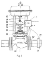
- an actuator which consists essentially of a valve body 10, a pneumatic diaphragm actuator 12 and an "intelligent" positioner 14.
- An intelligent positioner 14 is understood here to mean a positioner provided with processor capabilities, which is able to record and process certain variables in order to influence them accordingly or to control corresponding displays.
- the valve 10 is installed in a pipeline 16 and controls the passage of a medium through a corresponding stroke of a closing body interacting with a valve seat. For a given pressure or differential pressure, a certain flow rate results depending on the valve stroke.
- the pneumatic diaphragm actuator 12 is connected to the valve upper part by means of stud bolts 18 and nuts 20 pull a stuffing box and packing (not shown here in more detail) via a stuffing box gland 22 to seal a valve rod 24 in the upper part of the valve.
- a connecting piece 26 connects the valve rod 24 to a rod 28 of the pneumatic diaphragm actuator 12.
- a lever 30 acts on the connecting piece 26 and acts on a position transmitter 32, preferably a potentiometer of the positioner 14.
- the actual task of the positioner 14 is to convert a standardized electrical signal of, for example, 4-20 mA into a pneumatic pressure signal which is fed to the pneumatic drive 12 and results in a corresponding position of the valve rod 24. Via the potentiometer 32 shown, the actual value be compared electrically with the electrical setpoint signal.
- the processor contained in the positioner 14 is designed as a digital signal processor and connected to various sensors. These sensors are formed by the position sensor 32, a sensor 34 monitoring the tightness of the stuffing box, which is preferably a pressure sensor, a structure-borne noise sensor 36, which is arranged on a crossbar connected to the valve upper part, and a flow sensor 38, which can be provided with the actuator or can also be integrated in the form of a vortex sensor 38 'in a flange eye of the valve body 10.
- the feedback of the actual value signal predetermined by the position sensor 32 could also be replaced by a pressure sensor in the pneumatic drive 12. Additional pressure sensors can be provided to measure the pressure of the medium or the differential pressure of the medium.
- the positioner 14 is provided with a standardized interface in order to communicate via a fieldbus with a central control room of a process control system or to specify a connection for a portable personal computer. Furthermore, the PID controller usually provided in the control room can be integrated in the positioner.
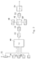
- FIG. 2 shows the circuitry of the processor contained in the positioner 14 insofar as it is required for the implementation of the present invention.
- the various analog sensors 32-38 are connected to an analog / digital converter 44 via a multiplexer 40 and possibly an amplifier 42, whose digital output signals are fed to a digital signal processor 46, which is connected in the usual way to a read-only memory ROM-48 and a random access memory ROM-50, in order to prepare and analyze the digitized measured values in accordance with programs stored in the ROM and with predetermined ones Compare standard and level values in order to set an error display in the event of an impermissible deviation or to control an analog display 54 via a digital / analog converter 52.
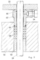
- FIG. 3 shows an exemplary embodiment for monitoring the tightness of the stuffing box with a pressure sensor 34.
- the valve rod 24 is centered in the valve upper part 56 by means of a guide bush 58 and is sealed off from the outside by an adjustable packing consisting of a plurality of packing rings 60.
- an adjustable packing consisting of a plurality of packing rings 60.
- a perfect seal is achieved with minimal friction or hysteresis. In practice, however, permanent tightness cannot be maintained. It is therefore necessary to readjust the packing from time to time, the nuts 20 of the gland follower 22 according to FIG. 1 having to be tightened.
- a stuffing box 62 moves further into the upper part and compresses the partly elastic packing rings, which thereby nestle more tightly on the valve rod 24 or on the walls of the upper part 56 and produce tightness again.
- the O-ring 64 is arranged statically between the stuffing box 62 and the valve upper part 56 and the O-ring 66 is arranged dynamically between the valve rod 24 and the stuffing box 62. If one now assumes that the static seal by means of the O-ring 64 is completely tight and the dynamic seal by means of the O-ring 66 retains at least the majority of a leak, then a pressure must build up within the special gland 62 the miniature pressure sensor 34 is detected and converted into an electrical signal. This signal is fed to the existing positioner and evaluated in the processor.
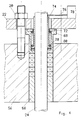
- the special stuffing box 68 contains a spring 70 which is held down by a plate 72.
- the spring ensures that a leakage quantity indicator 74 in the form of a piston always assumes an extreme lower position in the absence of a leakage quantity.
- the piston-shaped indicator 74 which is made of a corrosion-resistant material with good sliding properties, e.g. consists of PTFE, pushed upwards, touching an actuating plate 76 of a microswitch 78 and triggering a signal. Sealing lips on the lower part of the piston-shaped indicator are pressed by a spreading ring 80 both against the valve rod 24 and against the inner wall of the special stuffing box 68 and ensure a tight seal.
- the signal from the microswitch 78 is in turn fed to the processor in the positioner.
- the basic characteristic curve including the reversal range U and hysteresis H, is determined under practical conditions, according to FIG Stroke of the drive is recorded. This is possible in a simple manner with the aid of the position transmitter 32 according to FIG. 1.
- the recorded characteristic curve is stored in the memory assigned to the microprocessor.
- the throttle element is usually a variable cross-section inside the valve, usually a concentric seat ring and a so-called cone is used as the closing body, which dips into the seat ring and - depending on the travel path, i. H. from the stroke - the throttle cross-section adjusted.
- a typical operating characteristic is shown in Fig. 7, with the controlled variable, i.e. in the present case the flow is shown.
- the average or local gain of the actuator which is determined on the basis of the slope dX / dQ, can also be taken into account, where dQ is the change in flow, e.g. in kg / h when the input signal dX changes, e.g. in mA or as a digital variable.
- dQ is the change in flow, e.g. in kg / h when the input signal dX changes, e.g. in mA or as a digital variable.
- a tolerance band is established both for the permitted course of the basic characteristic curve according to FIGS. 5 and 6 and for the course of the operating characteristic curve according to FIGS. 7 and 8, and furthermore limit values for the differential quotient dx / dQ, which expresses the slope of the operating characteristic. As soon as this tolerance band or the limit values of the operating curve steepness are exceeded, an alarm is output in the diagnostic status. Indications of possible causes of damage result from the direction and size of the deviations from the initial characteristics.
- FIG. 9 shows a typical reproducible spectrum recorded by the structure-borne noise sensor in the normal operating state of the valve.
- the vibrations of the valve determined by an acceleration sensor are plotted against the frequency, preferably in a range from 2 to 10 kHz.
- Fig. 10 the band of thirds of the vibrations is dashed in a valve as good as new and in solid lines in a valve that is already damaged.
- a defective valve can also be identified here, and this measurement can be used in particular to determine wear due to corrosion, cavitation or erosion.
- All diagnoses are carried out either periodically by a built-in timer or permanently in the case of particularly critical regulations. A comparison is always made with the output characteristics and an alarm is triggered if there is a deviation by a predetermined amount. This alarm can be signaled in the central control room via the fieldbus. On the other hand, it is also possible to operate in one Process control system to initialize the diagnosis manually from the control room.
Abstract
Description
Die vorliegende Erfindung bezieht sich auf ein Diagnose-System nach dem Gattungsbegriff des Patentanspruches 1.The present invention relates to a diagnostic system according to the preamble of claim 1.
Ein ständig steigender Wettbewerb in der freien Wirtschaft machen Kostensenkungen und eine Verbesserung der Effizienz notwendig. Diese Forderung ist am ehesten durch eine bessere Auslastung bestehender Anlagen und eine Steigerung der Anlagenleistung zu erreichen. Unvorhergesehene Stillstände von Anlagen oder Anlageteilen, verursacht durch ausgefallene Komponenten, wie beispielsweise Regelventile, Meßumformer, Durchflußmesser und dergl. vermindern die Produktionskapazität und die mögliche Auslastung einer Anlage ganz entscheidend. Eine Verminderung von Stillstandszeiten und eine erhöhte Anlagenzuverlässigkeit setzt eine möglichst genaue Kenntnis des aktuellen Anlagenzustandes und ihrer Komponenten voraus. Dies betrifft vor allem die unvermeidlichen Abnutzungsprozesse von Anlagenkomponenten.Constantly increasing competition in the free economy makes it necessary to cut costs and improve efficiency. The best way to achieve this requirement is to better utilize existing plants and increase plant performance. Unforeseen downtimes of plants or parts of plants, caused by failed components, such as control valves, transmitters, flow meters and the like, significantly reduce the production capacity and the possible utilization of a plant. A reduction in downtimes and increased plant reliability requires knowledge of the current plant status and its components that is as precise as possible. This concerns above all the inevitable wear processes of system components.
Strenge Auflagen der Behörden (Technische überwachungsvereine, Gewerbeaufsichtsämter usw.) in Bezug auf den immer dringlicher werdenden Umweltschutz, verlangen im Interesse einer Reinhaltung von Luft und Gewässer, daß jedwede Undichtigkeit von chemischen oder petrochemischen Anlagen vermieden und frühzeitig erkannt werden muß.Strict regulations by the authorities (technical surveillance associations, trade inspectorates, etc.) with regard to the increasingly urgent need for environmental protection require, in the interest of keeping the air and water clean, that any leakage from chemical or petrochemical plants must be avoided and recognized at an early stage.
In geschlossenen, drucktragenden Anlagen, wie sie vor allem in der chemischen und petro-chemischen Industrie, in konventionellen und Nuklearkraftwerken, sowie in Raffinierien und erdölverarbeitenden Anlagen auftreten, gestaltet sich eine Beurteilung des Abnutzungsgrades außerordentlich schwierig, weil eine Schadensfeststellung und entsprechende Wartungsmaßnahme normalerweise nicht ohne ein Abschalten der Anlage und den Ausbau der Anlagenkomponenten möglich ist.In closed, pressure-bearing plants, such as those that occur in the chemical and petrochemical industry, in conventional and nuclear power plants, as well as in refineries and petroleum-processing plants, an assessment of the degree of wear is extremely difficult because a damage assessment and corresponding maintenance measures are usually not without it is possible to switch off the system and expand the system components.
Wesentliche Bauelemente in derartigen Anlagen sind Regel- und Absperrarmaturen, d.h. Ventile, die in Kombination mit einem vorzugsweise pneumatischen Antrieb und einem Stellungsregler als Stellgeräte Verwendung finden. Übliche Schäden bei derartigen Stellgeräten - geordnet in etwa nach der Häufigkeit ihres Auftretens - sind folgende:
- 1. Undichte Stopfbuchse, verbunden mit Umweltverschmutzung
- 2. Hohe oder veränderliche Reibungskräfte, verbunden mit Hysteresis
- 3. Zunehmende Restleckmenge des Ventils in der geschlossenen Stellung
- 4. Störungen oder Ausfall des Ventil-Stellungsreglers
- 5. Schäden am Ventilantrieb (z.B. Reißen der Membrane)
- 6. Erosion bzw. Verschleiß der Innenteile durch andauernde Kavitation
- 7. Korrosionsschäden durch Wahl ungeeigneter Werkstoffe
- 8. Erosion der aus Schließkörper und Sitz bestehenden Garnitur, verbunden mit gestörtem Kennlinienverlauf.
- 9. Dauerbrüche von Innenteilen
- 10. Ausgeschlagene Führungen, Klappern ungenügende Reproduzierbarkeit.
- 1. Leaking gland connected to pollution
- 2. High or variable frictional forces associated with hysteresis
- 3. Increasing residual valve leakage in the closed position
- 4. Malfunctions or failure of the valve positioner
- 5. Damage to the valve drive (eg tearing of the membrane)
- 6. Erosion or wear of the internal parts due to continuous cavitation
- 7. Corrosion damage due to the selection of unsuitable materials
- 8. Erosion of the closing body and seat Set combined with a disturbed characteristic curve.
- 9. Fatigue breaks of internal parts
- 10. Knocked out guides, rattling insufficient reproducibility.
Aus der Zeitschrift "ölhydraulik und Pneumatik", 1981, Seiten 568-573 ist es bereits bekannt, bei hydraulischen Bauelementen durch Messung von Körperschall eine Schadensfrüherkennung durchzuführen, wobei Körperschallspektren im Neuzustand des hydraulischen Bauelementes und im laufenden Betrieb aufgenommen und miteinander verglichen werden und bei Abweichung um einen vorgegebenen Pegel auf einen entstehenden oder bereits bestehenden Schaden geschlossen wird. Die Untersuchungen werden dort an Flügelzellenpumpen, d.h. an Geräten mit rotierenden Teilen, vorgenommen, wobei insbesondere mechanischer Verschleiß und Kavitation feststellbar sind. Aus der US-PS 5 197 328 ist es ferner bekannt, Drücke und einen Stellweg eines Ventils zu erfassen und sie nach Analog/Digitalwandlung einem Prozessor zuzuführen, der die ordnungsgemäße Funktion des Ventils überwacht.From the magazine "Oil Hydraulics and Pneumatics", 1981, pages 568-573, it is already known to carry out early detection of damage to hydraulic components by measuring structure-borne noise, wherein structure-borne noise spectra are recorded and compared with one another in the new state of the hydraulic component and during operation and in the event of a deviation an existing or existing damage is concluded by a predetermined level. The investigations are carried out on vane pumps, i.e. on devices with rotating parts, in particular mechanical wear and cavitation can be determined. From US Pat. No. 5,197,328 it is also known to detect pressures and an actuating path of a valve and, after analog / digital conversion, to supply them to a processor which monitors the proper functioning of the valve.
Ausgehend von diesem Stand der Technik ist es die Aufgabe der vorliegenden Erfindung, eine nahezu lückenlose überwachung und Frühanzeige von Schadensfällen bei Regel- und Absperrarmaturen durchzuführen, so daß eine vorbeugende Wartung möglich ist.Based on this prior art, it is the object of the present invention to carry out an almost complete monitoring and early notification of damage to control and shut-off valves, so that preventive maintenance is possible.
Die Lösung dieser Aufgabe gelingt gemäß den kennzeichnenden Merkmalen des Patentanspruches 1. Weitere vorteilhafte Ausgestaltungen des erfindungsgemäßen Diagnose-Systems sind den abhängigen Ansprüchen entnehmbar.This object is achieved in accordance with the characterizing features of patent claim 1. Further advantageous refinements of the diagnostic system according to the invention can be found in the dependent claims.
Anhand der Figuren der beiliegenden Zeichnung seien im folgenden das erfindungsgemäße Diagnose-System sowie Elemente zur Verwirklichung dieses Systems näher beschrieben. Es zeigen:
- Fig. 1
- die prinzipielle Anordnung eines Stellgerätes, bestehend aus einem Regelventil mit pneumatischem Antrieb und Stellungsregler;
- Fig. 2
- wesentliche Komponenten eines intelligenten Stellungsreglers;
- Fig. 3
- einen Teil des Regelventils mit Spezialstopfbuchse und Drucksensor zur Erkennung von Undichtheiten;
- Fig. 4
- Teile eines Regelventils mit Spezialstopfbuchse und mechanischer Abtastung zur Erkennung von Undichtheiten;
- Fig. 5
- die typische Grundkennlinie eines Regelventils;
- Fig. 6
- eine Entartung dieser Grundkennlinie bei einem Antriebsschaden;
- Fig. 7
- eine Betriebskennlinie des Regelventils;
- Fig. 8
- eine Entartung dieser Betriebskennlinie bei starkem Verschleiß des Drosselkörpers;
- Fig. 9
- ein typisches reproduzierbares Körperschallspektrum bei Normalbedingungen des Regelventils; und
- Fig. 10
- ein Terzband der aufintegrierten Körperschallschwingungen bei einem neuwertigen und einem bereits beschädigten Regelventil.
- Fig. 1
- the basic arrangement of an actuator, consisting of a control valve with pneumatic actuator and positioner;
- Fig. 2
- essential components of an intelligent positioner;
- Fig. 3
- part of the control valve with special stuffing box and pressure sensor to detect leaks;
- Fig. 4
- Parts of a control valve with special stuffing box and mechanical scanning for the detection of leaks;
- Fig. 5
- the typical basic characteristic of a control valve;
- Fig. 6
- a degeneracy of this basic characteristic when the drive is damaged;
- Fig. 7
- an operating characteristic of the control valve;
- Fig. 8
- a degeneracy of this operating characteristic when the throttle body is subject to excessive wear;
- Fig. 9
- a typical reproducible structure-borne noise spectrum under normal conditions of the control valve; and
- Fig. 10
- a third-octave band of the integrated structure-borne sound vibrations in a control valve that is as good as new and that has already been damaged.
Gemäß Fig. 1 ist ein Stellgerät dargestellt, welches im wesentlichen aus einem Ventilkörper 10, einem pneumatischen Membranantrieb 12 und einem "intelligenten" Stellungsregler 14 besteht. Unter intelligentem Stellungsregler 14 wird hierbei ein mit Prozessorfähigkeiten versehener Stellungsregler verstanden, der in der Lage ist, bestimmte Größen aufzunehmen und zu verarbeiten, um entsprechend Einfluß zu nehmen bzw. entsprechende Anzeigen zu steuern.1, an actuator is shown, which consists essentially of a
Das Ventil 10 ist in eine Rohrleitung 16 eingebaut und steuert durch einen entsprechenden Hub eines mit einem Ventilsitz zusammenwirkenden Schließkörpers den Durchtritt eines Mediums. Bei einem vorgegebenen Druck bzw. Differenzdruck ergibt sich in Abhängigkeit vom Ventilhub eine bestimmte Druchflußmenge.The
Der pneumatische Membranantrieb 12 ist über Stehbolzen 18 mit dem Ventiloberteil verbunden und Muttern 20 ziehen über eine Stopfbuchsenbrille 22 eine hier nicht näher erkennbare Stopfbuchse und Packung zur Abdichtung einer Ventilstange 24 im Ventiloberteil zusammen. Ein Verbindungsstück 26 verbindet die Ventilstange 24 mit einer Stange 28 des pneumatischen Membranantriebs 12. An dem Verbindungsstück 26 greift ein Hebel 30 an, der auf einen Stellungsgeber 32, vorzugsweise ein Potentiometer des Stellungsreglers 14, einwirkt. Die eigentliche Aufgabe des Stellungsreglers 14 besteht darin, ein normiertes elektrisches Signal von z.B. 4 - 20 mA in ein pneumatisches Drucksignal umzusetzen, das dem pneumatischen Antrieb 12 zugeführt wird und in einer entsprechenden Stellung der Ventilstange 24 resultiert. über das dargestellte Potentiometer 32 kann der Istwert elektrisch mit dem elektrischen Sollwertsignal verglichen werden.The
Der in dem Stellungsregler 14 enthaltene Prozessor ist als digitaler Signalprozessor ausgebildet und an verschiedene Sensoren angeschlossen. Diese Sensoren werden gebildet durch den Stellungssensor 32, ein die Dichtigkeit der Stopfbuchse überwachenden Sensor 34, der vorzugsweise ein Drucksensor ist, einen Körperschallsensor 36, der an einer mit dem Ventiloberteil verbundenen Traverse angeordnet ist und einen Durchflußsensor 38, der dem Stellgerät beigestellt werden kann oder auch in Form eines Vortex-Sensors 38' in ein Flanschauge des Ventilkörpers 10 integriert sein kann. Die durch den Stellungssensor 32 vorgegebene Rückführung des Istwertsignales könnte auch durch einen Drucksensor in dem pneumatischen Antrieb 12 ersetzt werden. Weitere Drucksensoren können vorgesehen sein, um den Druck des Mediums bzw. den Differenzdruck des Mediums zu messen. Der Stellungsregler 14 ist mit einer genormten Schnittstelle versehen, um über einen Feldbus mit einer zentralen Warte eines Prozeßleitsystems zu kommunizieren bzw. um einen Anschluß für einen tragbaren Personalcomputer vorzugeben. Ferner kann der üblicherweise in der Meßwarte vorgesehene PID-Regler in den Stellungsregler integriert sein.The processor contained in the
Fig. 2 zeigt die Beschaltung des in dem Stellungsregler 14 enthaltenen Prozessors, soweit sie für die Verwirklichung der vorliegenden Erfindung benötigt wird. Die verschiedenen analogen Sensoren 32 - 38 sind über einen Multiplexer 40 und ggf. einen Verstärker 42 an einen Analog/Digital-Wandler 44 angeschlossen, dessen digitale Ausgangssignale einem digitalen Signalprozessor 46 zugeführt werden, der in der üblichen Weise an einen Festwertspeicher ROM-48 und einen Speicher mit wahlfreiem Zugriff ROM-50 angeschlossen ist, um gemäß in dem ROM gespeicherten Programmen die digitalisierten Meßwerte aufzubereiten und zu analysieren und mit vorgegebenen Norm- und Pegelwerten zu vergleichen, um bei unzulässiger Abweichung eine Fehleranzeige zu setzen bzw. über einen Digital/Analog-Wandler 52 eine analoge Anzeige 54 zu steuern.2 shows the circuitry of the processor contained in the
Fig. 3 zeigt ein Ausführungsbeispiel zur überwachung der Dichtheit der Stopfbuchse mit einem Drucksensor 34. Die Ventilstange 24 ist im Ventiloberteil 56 mittels einer Führungsbuchse 58 zentriert und durch eine nachstellbare Packung, die aus mehreren Packungsringen 60 besteht, nach außen abgedichtet. Im Idealfall wird hierbei eine vollkommene Dichtheit bei minimaler Reibung bzw. Hysterese erreicht. In der Praxis ist jedoch eine dauernde Dichtheit nicht aufrechtzuerhalten. Deshalb ist von Zeit zu Zeit ein Nachstellen der Packung notwendig, wobei die Muttern 20 der Stopfbuchsenbrille 22 gemäß Fig. 1 angezogen werden müssen. Dabei bewegt sich eine Stopfbuchse 62 weiter in das Oberteil hinein und komprimiert die zum Teil elastischen Packungsringe, die sich dadurch fester an die Ventilstange 24 bzw. an die Wandungen des Oberteils 56 anschmiegen und erneut Dichtheit herstellen. Um ein regelmäßiges Nachstellen zu vermeiden, wurden spezielle Packungskonfigurationen bislang entwickelt, die z.B. durch Federn eine automatische Nachstellung der Packung gewährleisten sollen. Eine tatsächliche überprüfung der Dichtheit findet allerdings nicht statt. Diese überprüfung ist auch vom Wartungspersonal nicht immer auf einfache Art und Weise durchzuführen. Bei Flüssigkeiten ist eine Dichtheitsüberprüfung noch relativ einfach, weil sich Undichtheiten durch benetzte Oberflächen leicht nachweisen lassen. Auch bei Dampf als Betriebsstoff kann eine undichte Stangendurchführung durch Auftreten einer Dampffahne oder zumindest durch gesammeltes Kondenzwasser leicht erkannt werden. Bei Gasen wird die Überprüfung allerdings schon sehr schwierig, wenn man von stark riechenden Gasen einmal absieht. Durch Verwendung einer Spezialstopfbuchse, die zwei O-Ringe 64 und 66 enthält, ist jedoch - wie gezeigt - eine überprüfung der Dichtheit relativ einfach möglich. Der O-Ring 64 ist statisch zwischen der Stopfbuchse 62 und dem Ventiloberteil 56 angeordnet und der O-Ring 66 ist dynamisch zwischen Ventilstange 24 und Stopfbuchse 62 angeordnet. Geht man nunmehr davon aus, daß die statische Dichtung mittels des O-Ringes 64 vollkommen dicht ist und die dynamische Dichtung mittels des O-Ringes 66 zumindest den größten Teil einer Leckage zurückhält, so muß sich innerhalb der Spezialstopfbuchse 62 ein Druck aufbauen, der von dem Miniaturdrucksensor 34 erfaßt und in ein elektrisches Signal umgewandelt wird. Dieses Signal wird dem vorhandenen Stellungsregler zugeführt und in dem Prozessor ausgewertet.3 shows an exemplary embodiment for monitoring the tightness of the stuffing box with a
Fig. 4 zeigt eine modifizierte Anordnung zur überwachung der Dichtheit einer Stopfbuchsenanordnung. Dort enthält die Spezialstopfbuchse 68 eine Feder 70, die von einem Blech 72 niedergehalten wird. Die Feder sorgt dafür, daß ein Leckmengenindikator 74 in Form eines Kolbens beim Nichtvorhandensein einer Leckmenge stets eine extreme untere Position einnimmt.4 shows a modified arrangement for monitoring the tightness of a stuffing box arrangement. There, the
Beim Auftreten einer Packungsleckage wird wird der kolbenförmige Indikator 74, der aus einem korrosionsfesten Material mit guten Gleiteigenschaften, z.B. aus PTFE besteht, nach oben geschoben, wobei er ein Betätigungsblech 76 eines Mikroschalters 78 berührt und ein Signal auslöst. Dichtlippen am unteren Teil des kolbenförmigen Indikators werden von einem Spreizring 80 sowohl gegen die Ventilstange 24 als auch gegen die Innenwandung der Spezialstopfbuchse 68 gedrückt und sorgen für einen dichten Abschluß. Das Signal des Mikroschalters 78 wird wiederum dem Prozessor in dem Stellungsregler zugeführt.If a pack leak occurs, the piston-shaped
Zur Überwachung von zu großer Reibung (Hysterese) und der Funktionstüchtigkeit des pneumatischen Antriebs wird gemäß Fig. 5 vor Inbetriebnahme des kompletten Stellgerätes unter praxisnahen Bedingungen die Grundkennlinie einschließlich Umkehrspanne U und Hysterese H ermittelt, indem in Abhängigkeit von dem Eingangssignal X der Stellweg, d.h. der Hub des Antriebes aufgenommen wird. Dies ist in einfacher Weise mit Hilfe des Positionsgebers 32 gemäß Fig. 1 möglich. Die aufgenommene Kennlinie wird in dem dem Mikroprozessor zugeordneten Speicher abgespeichert. Im laufenden Betrieb des Stellgerätes deutet eine überschreitung der maximalen Hysterese H oder der normalen Umkehrspanne U auf eine erhöhte Reibung des Stellgerätes hin, was z.B. durch eine zu fest angezogene Stopfbuchse oder durch erhöhte innere Reibung in der Armatur bedingt sein kann. Auch diese Abweichungen von den Normwerten werden durch den Mikroprozessor signalisiert, da im Falle der Ignorierung dieser Erscheinungen nicht nur die Regelbarkeit des Stellgerätes leidet, sondern auch ein Fressen in der Führung und damit ein Totalausfall des Stellgerätes auftreten kann.To monitor excessive friction (hysteresis) and the functionality of the pneumatic drive, the basic characteristic curve, including the reversal range U and hysteresis H, is determined under practical conditions, according to FIG Stroke of the drive is recorded. This is possible in a simple manner with the aid of the
Ein anderer häufig anzutreffender Schadensfall ist ein Reißen oder Undichtwerden der Membran innerhalb des pneumatischen Antriebes. Dies äußert sich unweigerlich in einer Entartung der ursprünglich aufgenommenen und gespeicherten Kennlinie des Stellgerätes, wie dies in Fig. 6 veranschaulicht ist. In einem solchen Fall wird im Innern des Membranantriebs nicht mehr der volle Betriebsdruck aufgebaut, so daß der Stellweg entsprechend der Gegenkraft der Rückstellfedern verkürzt wird. Durch eine periodische oder permanente überwachung der Grundkennlinie des Stellgerätes werden auch solche Fehler und Schadensfälle diagnostizierbar.Another common damage is tearing or leaking of the diaphragm inside the pneumatic actuator. This inevitably manifests itself in a degeneracy of the characteristic curve of the actuator originally recorded and stored, as illustrated in FIG. 6. In such a case, the full operating pressure is no longer built up in the interior of the diaphragm drive, so that the actuating path is shortened in accordance with the counterforce of the return springs. Periodic or permanent monitoring of the basic characteristic of the actuator also makes it possible to diagnose such errors and damage.
Eine Lose oder ein partieller Verschleiß des Drosselelementes, d.h. des Schließkörpers des Ventils, beeinträchtigen die Regelbarkeit des Stellgerätes und sind daher auf jeden Fall zu vermeiden. Das Drosselelement ist in der Regel ein veränderlicher Querschnitt im Innern der Armatur, üblicherweise wird ein konzentrischer Sitzring und ein sogenannter Kegel als Schließkörper verwendet, der in den Sitzring eintaucht und - abhängig vom Stellweg, d. h. vom Hub - den Drosselquerschnitt verstellt. Eine übliche Betriebskennlinie ist in Fig. 7 dargestellt, wobei über dem Eingangssignal X die Regelgröße, d.h. im vorliegenden Fall der Durchfluß dargestellt ist.Loose or partial wear of the throttle element, i.e. of the closing body of the valve impair the controllability of the actuator and should therefore be avoided in any case. The throttle element is usually a variable cross-section inside the valve, usually a concentric seat ring and a so-called cone is used as the closing body, which dips into the seat ring and - depending on the travel path, i. H. from the stroke - the throttle cross-section adjusted. A typical operating characteristic is shown in Fig. 7, with the controlled variable, i.e. in the present case the flow is shown.
Lose und Verschleiß äußern sich in einem unstetigen Verlauf dieser Betriebskennlinie. Dabei kann sich die Verstärkung des Regelkreises erheblich verändern, was zu einem instabilen Betrieb führt, wie dies in Fig. 8 dargestellt ist. Hat man die Betriebskennlinie bei normalen Prozeßbedingungen gemäß Fig. 7 bei Inbetriebnahme des Stellgerätes als Funktion des Reglereingangssignals X aufgenommen und in dem dem Prozessor zugeordneten Speicher abgespeichert, so ist es bei vorhandenem Durchflußmesser möglich, jegliche Abweichung von dieser normalen Betriebskennlinie festzustellen. Da allerdings auch bei geänderten Betriebsbedingungen, z.B. bei geringerem Eingangsdruck die Betriebskennlinie des Durchflusses verändert wird, erfordert eine genaue Beurteilung des Zustandes noch die Berücksichtigung weiterer Einflußgrößen, wie z.B. den Eingangsdruck oder den Differenzdruck.Loose and wear are expressed in an inconsistent course of this operating characteristic. The gain of the control loop can change considerably, which leads to an unstable one Operation performs as shown in FIG. 8. If the operating characteristic under normal process conditions according to FIG. 7 was recorded as a function of the controller input signal X when the actuator was started up and stored in the memory assigned to the processor, it is possible to determine any deviation from this normal operating characteristic when there is a flow meter. However, since the operating characteristic of the flow is changed even under changed operating conditions, for example with a lower inlet pressure, a precise assessment of the condition also requires consideration of other influencing variables, such as the inlet pressure or the differential pressure.
Auch kann man die mittlere oder lokale Verstärkung des Stellgerätes, die anhand der Kennliniensteilheit dX/dQ ermittelt wird, in Betracht ziehen, wobei dQ die Durchflußänderung, z.B. in kg/h bei einer Änderung des Eingangssignales dX, z.B. in mA oder als digitale Größe darstellt. Da bei einer integrierten Lösung, d.h. bei dem Prozeßregler im Stellungsreglergehäuse der zuletzt genannte Wert identisch mit dem Reglerausgangssignal Y ist, müssen natürlich auch die Einstellparameter des PID-Reglers, die gewöhnlich nach der Grundeinstellung bei der Inbetriebnahme nicht mehr verändert werden, mit in Betracht gezogen werden.The average or local gain of the actuator, which is determined on the basis of the slope dX / dQ, can also be taken into account, where dQ is the change in flow, e.g. in kg / h when the input signal dX changes, e.g. in mA or as a digital variable. With an integrated solution, i.e. In the case of the process controller in the positioner housing, the last-mentioned value is identical to the controller output signal Y, the setting parameters of the PID controller, which usually do not need to be changed after commissioning, must of course also be taken into account.
Sowohl für den erlaubten Verlauf der Grundkennlinie nach den Figuren 5 und 6, als auch für den Verlauf der Betriebskennlinie nach den Figuren 7 und 8 wird ein Toleranzband festgelegt und ferner werden Grenzwerte für den Differentialquotienten dx/dQ, der die Steilheit der Betriebskennlinie ausdrückt, ermittelt. Sobald dieses Toleranzband oder die Grenzwerte der Betriebskennliniensteilheit überschritten werden, wird im Diagnosestatus ein Alarm ausgegeben. Hinweise für mögliche Schadensursachen ergeben sich aus der Richtung und Größe der Abweichungen von den Ausgangskennlinien.A tolerance band is established both for the permitted course of the basic characteristic curve according to FIGS. 5 and 6 and for the course of the operating characteristic curve according to FIGS. 7 and 8, and furthermore limit values for the differential quotient dx / dQ, which expresses the slope of the operating characteristic. As soon as this tolerance band or the limit values of the operating curve steepness are exceeded, an alarm is output in the diagnostic status. Indications of possible causes of damage result from the direction and size of the deviations from the initial characteristics.
Figur 9 zeigt ein typisches reproduzierbares, durch den Körperschallsensor aufgenommenes Spektrum im Normal-Betriebszustand des Ventils. Hierbei sind die durch einen Beschleunigungsaufnehmer ermittelten Schwingungen des Ventils über der Frequenz, vorzugsweise in einem Bereich von 2 - 10 kHz, aufgetragen.FIG. 9 shows a typical reproducible spectrum recorded by the structure-borne noise sensor in the normal operating state of the valve. Here, the vibrations of the valve determined by an acceleration sensor are plotted against the frequency, preferably in a range from 2 to 10 kHz.
In Fig. 10 ist das Terzband der Schwingungen bei einem neuwertigen Ventil gestrichelt und bei einem bereits beschädigten Ventil in ausgezogenen Linien dargestellt. Durch Bildung des Flächenintegrals und Vorgabe einer tolerierbaren Abweichung kann auch hier ein schadhaftes Ventil erkannt werden, wobei sich durch diese Messung insbesondere Verschleiß bedingt durch Korrosion, Kavitation oder Erosion feststellen lassen.In Fig. 10 the band of thirds of the vibrations is dashed in a valve as good as new and in solid lines in a valve that is already damaged. By forming the surface integral and specifying a tolerable deviation, a defective valve can also be identified here, and this measurement can be used in particular to determine wear due to corrosion, cavitation or erosion.
Alle Diagnosen werden entweder periodisch durch einen eingebauten Zeitgeber oder bei besonders kritischen Regelungen permanent durchgeführt. Immer wird ein Vergleich mit den Ausgangskennlinien durchgeführt und bei Abweichung um einen vorbestimmten Betrag ein Alarm ausgelöst. Dieser Alarm kann in die zentrale Warte über den Feldbus signalisiert werden. Andererseits ist es auch möglich, bei einem Betrieb in einem Prozeßleitsystem die Diagnose manuell von der Warte aus zu initialisieren.All diagnoses are carried out either periodically by a built-in timer or permanently in the case of particularly critical regulations. A comparison is always made with the output characteristics and an alarm is triggered if there is a deviation by a predetermined amount. This alarm can be signaled in the central control room via the fieldbus. On the other hand, it is also possible to operate in one Process control system to initialize the diagnosis manually from the control room.
Selbstverständlich kann auch eine Weiterverarbeitung und Registrierung der Meßwerte mittels Personalcomputer und entsprechender Software direkt am Stellgerät erfolgen. Hierbei ist eine graphische Erfassung und Darstellung aller Meßwerte und Kennlinien möglich.Of course, further processing and registration of the measured values by means of a personal computer and corresponding software can also take place directly on the control device. Here, a graphical recording and representation of all measured values and characteristic curves is possible.
Claims (17)
Applications Claiming Priority (2)
| Application Number | Priority Date | Filing Date | Title |
|---|---|---|---|
| DE4326343 | 1993-08-05 | ||
| DE19934326343 DE4326343A1 (en) | 1993-08-05 | 1993-08-05 | Diganose system for control and shut-off valves |
Publications (1)
| Publication Number | Publication Date |
|---|---|
| EP0637713A1 true EP0637713A1 (en) | 1995-02-08 |
Family
ID=6494553
Family Applications (1)
| Application Number | Title | Priority Date | Filing Date |
|---|---|---|---|
| EP94112112A Withdrawn EP0637713A1 (en) | 1993-08-05 | 1994-08-03 | Diagnostic system for control- and shut-off-valves |
Country Status (3)
| Country | Link |
|---|---|
| EP (1) | EP0637713A1 (en) |
| CA (1) | CA2129470A1 (en) |
| DE (1) | DE4326343A1 (en) |
Cited By (58)
| Publication number | Priority date | Publication date | Assignee | Title |
|---|---|---|---|---|
| DE4447309A1 (en) * | 1994-12-31 | 1996-07-11 | Rtk Regeltechnik Kornwestheim | Control valve control method |
| WO1996030684A1 (en) * | 1995-03-31 | 1996-10-03 | Institut Für Sicherheitstechnologie (Istec) Gmbh | Process for monitoring and operating valve units, in particular motor-driven valve units |
| DE19524237A1 (en) * | 1995-07-04 | 1997-01-16 | Baelz Gmbh Helmut | Electromagnetic control valve for hazardous fluid esp. hot cooking oil in deep fat fryer - in which condition of metallic bellows seal is continuously monitored, with geared stepper motor controlled according to thermostat reading |
| DE29612775U1 (en) * | 1996-07-23 | 1997-08-21 | Siemens Ag | Positioner and control valve with such a positioner |
| FR2764037A1 (en) | 1997-06-03 | 1998-12-04 | Samson Ag | REGULATORY APPARATUS |
| FR2764712A1 (en) * | 1997-06-05 | 1998-12-18 | Samson Ag | METHOD AND DEVICE FOR MONITORING A CONTROLLER |
| WO1999015823A1 (en) * | 1997-09-22 | 1999-04-01 | Fisher Controls International, Inc. | Diagnostic device and method for pressure regulator |
| WO1999017042A1 (en) * | 1997-09-29 | 1999-04-08 | Fisher Controls International, Inc. | Method of and apparatus for deterministically obtaining measurements of a process control device parameter while a process is operating on-line |
| US5966679A (en) * | 1995-10-30 | 1999-10-12 | Fisher Controls International, Inc. | Method of and apparatus for nonobtrusively obtaining on-line measurements of a process control device parameter |
| US5993744A (en) * | 1994-07-11 | 1999-11-30 | Tekmar Company | Apparatus for introducing standards into a vial |
| EP0972979A2 (en) * | 1998-07-16 | 2000-01-19 | SMC Kabushiki Kaisha | Positioner and its setting method |
| US6056008A (en) * | 1997-09-22 | 2000-05-02 | Fisher Controls International, Inc. | Intelligent pressure regulator |
| WO2000073688A1 (en) | 1999-05-27 | 2000-12-07 | Siemens Aktiengesellschaft | Diagnostic system for a valve that can be actuated by a position controller via a drive |
| DE19947129A1 (en) * | 1999-09-30 | 2001-04-05 | Siemens Ag | Diagnosis system, especially for control |
| WO2001075344A1 (en) | 2000-04-04 | 2001-10-11 | Siemens Aktiengesellschaft | Positioner, especially for a valve that can be actuated by a drive |
| EP1156249A1 (en) * | 2000-05-19 | 2001-11-21 | Siemens Aktiengesellschaft | Device for positioning and holding a magnet and a position controller containing this device |
| WO2001088423A1 (en) | 2000-05-19 | 2001-11-22 | Siemens Aktiengesellschaft | Position controller especially for a drive actuated valve having inherent safety design |
| WO2002017028A1 (en) * | 2000-08-22 | 2002-02-28 | Fisher Controls International, Inc. | Method for detecting plug wear |
| US20020040284A1 (en) * | 1997-09-29 | 2002-04-04 | Junk Kenneth W. | Detection and discrimination of instabilities in process control loops |
| US6426225B1 (en) | 1994-07-11 | 2002-07-30 | Tekmar Company | Method of calibrating a vial autosampler |
| US6466893B1 (en) | 1997-09-29 | 2002-10-15 | Fisher Controls International, Inc. | Statistical determination of estimates of process control loop parameters |
| DE10218830C1 (en) * | 2002-04-26 | 2003-12-18 | Siemens Ag | Diagnostic system and method for a valve |
| DE19961064B4 (en) * | 1998-12-17 | 2004-05-06 | Cummins Inc., Columbus | Device and method for detecting fault conditions for an internal combustion engine |
| DE10254219A1 (en) * | 2002-11-20 | 2004-06-09 | Helmut Bälz GmbH | Flow valve monitoring device for industrial process plant evaluating stored data for providing warning signal when maintenance is required |
| WO2004102052A1 (en) | 2003-05-16 | 2004-11-25 | Siemens Aktiengesellschaft | Diagnostic system and method for a valve, especially a check valve of a positive displacement pump |
| EP1502031A1 (en) * | 2002-05-03 | 2005-02-02 | Fisher Controls International, Inc. | Method and apparatus for performing diagnostics in a control loop of a control valve |
| DE19724754B4 (en) * | 1996-06-06 | 2006-06-29 | Yamatake Corp. | Method and device for detecting an abnormality in a control valve |
| WO2007099057A2 (en) * | 2006-02-28 | 2007-09-07 | Auma Riester Gmbh+Co. Kg | Method and device for the monitoring, diagnosis or adjustment of an actuator for actuating a fitting |
| CN100394331C (en) * | 2006-06-09 | 2008-06-11 | 浙江大学 | Implementing method of intelligent flow control valve and valve |
| US7444191B2 (en) | 2005-10-04 | 2008-10-28 | Fisher-Rosemount Systems, Inc. | Process model identification in a process control system |
| WO2009040349A1 (en) * | 2007-09-24 | 2009-04-02 | Siemens Aktiengesellschaft | Diagnostic system and diagnostic method for a valve, particularly a closing valve or a control valve |
| CN101451562A (en) * | 2007-12-06 | 2009-06-10 | Abb股份公司 | Method for identifuing and adjusting drive type of drive device |
| CN101719410A (en) * | 2008-10-02 | 2010-06-02 | 罗伯特.博世有限公司 | Method and control unit for operating an injection valve |
| US7738975B2 (en) | 2005-10-04 | 2010-06-15 | Fisher-Rosemount Systems, Inc. | Analytical server integrated in a process control network |
| DE102008062846A1 (en) | 2008-12-23 | 2010-07-01 | Scheugenpflug Ag | Piston dispenser with monitored valve |
| US8036760B2 (en) | 2005-10-04 | 2011-10-11 | Fisher-Rosemount Systems, Inc. | Method and apparatus for intelligent control and monitoring in a process control system |
| CN102734549A (en) * | 2011-03-29 | 2012-10-17 | 阿自倍尔株式会社 | Cavitation diagnosis device and diagnosis method thereof |
| CN101372993B (en) * | 2007-08-22 | 2012-12-05 | Abb股份公司 | Method of identifying and adjusting drive type of drive |
| WO2013012849A1 (en) * | 2011-07-21 | 2013-01-24 | Fisher Controls International Llc | Control valve monitoring system |
| WO2013079690A1 (en) * | 2011-11-30 | 2013-06-06 | Visteon Global Technologies, Inc. | Valve sensor arrangement for motor vehicle air conditioning systems |
| WO2014168908A3 (en) * | 2013-04-09 | 2015-08-20 | Fisher Controls International Llc | Intelligent actuator and method of monitoring actuator health and integrity |
| CN105042174A (en) * | 2015-08-21 | 2015-11-11 | 厦门医学高等专科学校 | Monitoring and alarming device for inlet and outlet valves of culture tank and implementing method of monitoring and alarming device |
| EP2698570A3 (en) * | 2012-08-16 | 2015-12-02 | Samson Aktiengesellschaft | Device and method for quantifying a leakage flow at a positioning device |
| WO2016062328A1 (en) * | 2014-10-20 | 2016-04-28 | Aktiebolaget Skf | Valve operator assembly and valve equipped with such assembly |
| WO2016203273A1 (en) * | 2015-06-19 | 2016-12-22 | Seetru Limited | Safety valve leak analysis system |
| WO2018083176A1 (en) * | 2016-11-03 | 2018-05-11 | Vat Holding Ag | Vacuum valve system for a regulated operation of a vacuum process |
| DE102017100956A1 (en) | 2017-01-18 | 2018-07-19 | Samson Aktiengesellschaft | Optical microphone for the diagnosis of actuators |
| CN108953273A (en) * | 2018-09-17 | 2018-12-07 | 杜商精机(嘉兴)有限公司 | A kind of robot dedicated hydraulic control valve |
| WO2019231707A1 (en) * | 2018-06-01 | 2019-12-05 | Saudi Arabian Oil Company | Choke valve with internal sleeve for erosion protection |
| DE102018114710A1 (en) * | 2018-06-19 | 2019-12-19 | Samson Aktiengesellschaft | Detect poor seat integrity in a control valve |
| EP3599402A1 (en) * | 2018-07-25 | 2020-01-29 | SISTO Armaturen S.A. | Control air connection of a pneumatic unit |
| US10962440B2 (en) | 2016-03-18 | 2021-03-30 | Rotork Uk Limited | Valve operator including a fugitive emissions detector, and a method of detecting fugitive emissions from an industrial valve |
| CN112984197A (en) * | 2021-02-04 | 2021-06-18 | 大连海事大学 | Fault-monitorable electromagnetic valve |
| EP3851713A1 (en) * | 2020-01-20 | 2021-07-21 | SISTO Armaturen S.A. | System for condition monitoring |
| EP3851711A1 (en) * | 2020-01-20 | 2021-07-21 | SISTO Armaturen S.A. | Method for monitoring membrane valves |
| CN113503395A (en) * | 2021-08-02 | 2021-10-15 | 常州大学 | Dead monitoring system of LNG gas cylinder liquid outlet valve card |
| EP4043769A1 (en) * | 2021-02-05 | 2022-08-17 | Gemü Gebr. Müller Apparatebau GmbH & Co. Kommanditgesellschaft | Method for measuring acceleration in a process valve, and process valve |
| DE102021211592A1 (en) | 2021-10-14 | 2023-04-20 | Siemens Aktiengesellschaft | Method of operation for a valve system, valve system, control unit and computer program product |
Families Citing this family (21)
| Publication number | Priority date | Publication date | Assignee | Title |
|---|---|---|---|---|
| FI104129B (en) * | 1996-06-11 | 1999-11-15 | Neles Jamesbury Oy | Procedure for monitoring the condition of control valve |
| DE19637607A1 (en) * | 1996-09-16 | 1998-03-19 | Trw Fahrzeugelektrik | Pressure switch device, in particular for automotive technology |
| DE19704843A1 (en) * | 1997-02-08 | 1998-08-13 | Bayerische Motoren Werke Ag | Method of adjusting level indicator for vehicle storage container |
| JP2000046665A (en) | 1998-07-29 | 2000-02-18 | Smc Corp | Multichannel pressure sensor controller |
| DE20304894U1 (en) * | 2003-03-26 | 2003-07-31 | Buerkert Werke Gmbh & Co | Fluid flow control system, e.g. for regulating the flow speed of transport gas, comprises a valve mounted in a prefabricated unit, with pressure transmitters and electronic controller, for ease of installation |
| DE102004006354B4 (en) * | 2004-02-10 | 2007-02-22 | Abb Research Ltd. | Device for assessing the maintenance status of a valve |
| DE102006061815A1 (en) * | 2006-12-21 | 2008-06-26 | Endress + Hauser Conducta Gesellschaft für Mess- und Regeltechnik mbH + Co. KG | Retractable housing |
| DE102007020597A1 (en) * | 2007-05-02 | 2009-01-02 | Siemens Ag | Method for checking the functionality of a positioning device |
| DE102008058208B4 (en) | 2008-11-19 | 2017-01-05 | Samson Aktiengesellschaft | Actuator and method for checking the correct functioning of a bellows of a control device |
| US8555917B2 (en) * | 2009-03-26 | 2013-10-15 | Areva Np Inc | Power line data acquisition |
| DE102011078881A1 (en) * | 2011-07-08 | 2013-01-10 | Krones Aktiengesellschaft | Detection of cracks on metal bellows of valves |
| CN102890115B (en) * | 2011-07-21 | 2018-04-13 | 费希尔控制国际公司 | control valve monitoring system |
| DE102012017320B4 (en) | 2012-09-03 | 2014-08-28 | Siepmann-Werke Gmbh & Co. Kg | Apparatus and method for monitoring control or shut-off valves |
| DE102014015888B4 (en) | 2014-10-27 | 2018-10-04 | Samson Ag | Stellarmatur comprising a sealing arrangement |
| DE102014015889A1 (en) | 2014-10-27 | 2016-05-12 | Samson Ag | Stellarmatur comprising a sealing arrangement |
| DE102015105483B4 (en) * | 2015-04-10 | 2023-07-06 | Bürkert Werke GmbH | valve drive |
| DE102016216923B4 (en) | 2016-09-07 | 2018-07-26 | Festo Ag & Co. Kg | Method for detecting a valve state and drive head for carrying out the method |
| DE102018111019B4 (en) * | 2018-05-08 | 2023-08-03 | Witzenmann Gmbh | Movable metal component |
| DE102018130579A1 (en) * | 2018-11-30 | 2020-06-04 | Gemü Gebr. Müller Apparatebau Gmbh & Co. Kommanditgesellschaft | Shut-off device, component for a shut-off device, control unit for a shut-off device and method for operating a shut-off device |
| DE102019135598A1 (en) * | 2019-12-20 | 2021-06-24 | Endress+Hauser Conducta Gmbh+Co. Kg | Intelligent safety fitting and control method of an intelligent safety fitting |
| FR3108381B1 (en) | 2020-03-19 | 2022-06-10 | Asco Sas | Assembly comprising a valve and at least one fitting |
Citations (5)
| Publication number | Priority date | Publication date | Assignee | Title |
|---|---|---|---|---|
| JPS59155533A (en) * | 1983-02-25 | 1984-09-04 | Toshiba Corp | Gas turbine plant |
| EP0315391A2 (en) * | 1987-10-30 | 1989-05-10 | Westinghouse Electric Corporation | Online valve diagnostic monitoring system |
| US4896101A (en) * | 1986-12-03 | 1990-01-23 | Cobb Harold R W | Method for monitoring, recording, and evaluating valve operating trends |
| US5115672A (en) * | 1991-02-11 | 1992-05-26 | Westinghouse Electric Corp. | System and method for valve monitoring using pipe-mounted ultrasonic transducers |
| EP0517280A2 (en) * | 1991-06-07 | 1992-12-09 | SIHI GmbH & Co KG | Shaft passage |
Family Cites Families (26)
| Publication number | Priority date | Publication date | Assignee | Title |
|---|---|---|---|---|
| US3727520A (en) * | 1970-11-06 | 1973-04-17 | Sperry Rand Corp | Digital electrohydraulic servo system |
| SU446755A1 (en) * | 1972-12-28 | 1974-10-15 | Предприятие П/Я А-1639 | Mass flow meter |
| GB2077434B (en) * | 1980-05-30 | 1984-04-26 | Millar John | Ascertaining flow rate through valves or pumps |
| DE3148735A1 (en) * | 1981-12-09 | 1986-10-09 | Fried. Krupp Gmbh, 4300 Essen | Method and device for frequency analysis |
| DE3236815C2 (en) * | 1982-10-05 | 1985-09-19 | Klaus Dipl.-Ing.(FH) 3200 Hildesheim Metzger | Monitoring and control device on pipelines for the transport of liquids |
| GB8402538D0 (en) * | 1984-01-31 | 1984-03-07 | Glaxo Group Ltd | Automation unit |
| US4735101A (en) * | 1985-06-06 | 1988-04-05 | Charbonneau & Godfrey Associates | Motor operated valve analysis and testing system with monitoring of spring pack movement through torque switch post |
| US4891975A (en) * | 1986-04-04 | 1990-01-09 | Movats Incorporated | Method and apparatus for remote monitoring of valves and valve operators |
| US4916641A (en) * | 1987-01-16 | 1990-04-10 | Acl Technologies, Inc. | Servovalve analyzer system |
| US4762992A (en) * | 1987-06-10 | 1988-08-09 | Kollmorgen Corporation | Error detection system for two-state fiber optic sensors |
| SU1580164A1 (en) * | 1988-04-08 | 1990-07-23 | Предприятие П/Я В-8116 | Method of checking position of inner element of automatic system |
| DE3812101A1 (en) * | 1988-04-12 | 1989-11-02 | Martin Pfeil | Measuring device for a large number of measuring points |
| US5197328A (en) * | 1988-08-25 | 1993-03-30 | Fisher Controls International, Inc. | Diagnostic apparatus and method for fluid control valves |
| DE3907419A1 (en) * | 1989-03-08 | 1990-09-13 | Ingenieurgesellschaft Fuer Beh | Method for preventing damage in a machine or device |
| EP0425898A1 (en) * | 1989-10-31 | 1991-05-08 | Siemens Aktiengesellschaft | Process for controlling the transmission of measured values from a sensor to a central control unit using an input/output module |
| US5119683A (en) * | 1990-09-07 | 1992-06-09 | Motorola, Inc. | Solenoid controller with flyback pulses useful for diagnostics and/or control |
| DE4105062C2 (en) * | 1990-09-19 | 1997-01-23 | Helmut Prof Dipl Ing Hoenicke | Electropneumatic positioner with pulse width control |
| DE4035656B4 (en) * | 1990-11-09 | 2006-05-18 | Friatec Aktiengesellschaft | Compound slider with control |
| DE4036684C1 (en) * | 1990-11-17 | 1991-12-19 | Hermann Sewerin Gmbh, 4830 Guetersloh, De | Water pipe section tester esp. for hydrant or slide valve - has sound pick=up on one side and piezo-discs on other side of receptor |
| DE4105283A1 (en) * | 1991-02-20 | 1992-09-03 | Ultrakust Elektronic Gmbh | FLOW MEASURING DEVICE |
| DE4108460A1 (en) * | 1991-03-13 | 1992-09-17 | Salzgitter Anlagenbau | METHOD FOR QUICK REGULATING AND CONTROLLING A PROCESS IN A REACTOR AND MEASURING DEVICE FOR IMPLEMENTING THE METHOD |
| DE4111361A1 (en) * | 1991-04-09 | 1992-10-15 | Bosch Gmbh Robert | TANK VENTILATION SYSTEM AND METHOD AND DEVICE FOR CHECKING IT |
| DE9105473U1 (en) * | 1991-05-03 | 1991-07-04 | Uhde, Wilhelm, 3355 Kalenfeld, De | |
| JPH0569996A (en) * | 1991-09-05 | 1993-03-23 | Smc Corp | Vacuum unit |
| JP3418411B2 (en) * | 1991-09-06 | 2003-06-23 | Smc株式会社 | Vacuum unit |
| DE4200302C2 (en) * | 1992-01-09 | 1995-08-10 | Telefunken Microelectron | Method for determining the coupling state of a truck with an electro-pneumatic brake system |
-
1993
- 1993-08-05 DE DE19934326343 patent/DE4326343A1/en not_active Withdrawn
-
1994
- 1994-08-03 EP EP94112112A patent/EP0637713A1/en not_active Withdrawn
- 1994-08-04 CA CA 2129470 patent/CA2129470A1/en not_active Abandoned
Patent Citations (5)
| Publication number | Priority date | Publication date | Assignee | Title |
|---|---|---|---|---|
| JPS59155533A (en) * | 1983-02-25 | 1984-09-04 | Toshiba Corp | Gas turbine plant |
| US4896101A (en) * | 1986-12-03 | 1990-01-23 | Cobb Harold R W | Method for monitoring, recording, and evaluating valve operating trends |
| EP0315391A2 (en) * | 1987-10-30 | 1989-05-10 | Westinghouse Electric Corporation | Online valve diagnostic monitoring system |
| US5115672A (en) * | 1991-02-11 | 1992-05-26 | Westinghouse Electric Corp. | System and method for valve monitoring using pipe-mounted ultrasonic transducers |
| EP0517280A2 (en) * | 1991-06-07 | 1992-12-09 | SIHI GmbH & Co KG | Shaft passage |
Non-Patent Citations (1)
| Title |
|---|
| PATENT ABSTRACTS OF JAPAN vol. 9, no. 3 (M - 349)<1726> 9 January 1985 (1985-01-09) * |
Cited By (112)
| Publication number | Priority date | Publication date | Assignee | Title |
|---|---|---|---|---|
| US5993744A (en) * | 1994-07-11 | 1999-11-30 | Tekmar Company | Apparatus for introducing standards into a vial |
| US6426225B1 (en) | 1994-07-11 | 2002-07-30 | Tekmar Company | Method of calibrating a vial autosampler |
| US6544799B1 (en) | 1994-07-11 | 2003-04-08 | Tekmar Company | Vial autosampler with vial stabilization member |
| DE4447309A1 (en) * | 1994-12-31 | 1996-07-11 | Rtk Regeltechnik Kornwestheim | Control valve control method |
| WO1996030684A1 (en) * | 1995-03-31 | 1996-10-03 | Institut Für Sicherheitstechnologie (Istec) Gmbh | Process for monitoring and operating valve units, in particular motor-driven valve units |
| DE19524237A1 (en) * | 1995-07-04 | 1997-01-16 | Baelz Gmbh Helmut | Electromagnetic control valve for hazardous fluid esp. hot cooking oil in deep fat fryer - in which condition of metallic bellows seal is continuously monitored, with geared stepper motor controlled according to thermostat reading |
| DE19524237C2 (en) * | 1995-07-04 | 2002-02-07 | Baelz Gmbh Helmut | Flow armature unit and operating method therefor |
| US5966679A (en) * | 1995-10-30 | 1999-10-12 | Fisher Controls International, Inc. | Method of and apparatus for nonobtrusively obtaining on-line measurements of a process control device parameter |
| DE19724754B4 (en) * | 1996-06-06 | 2006-06-29 | Yamatake Corp. | Method and device for detecting an abnormality in a control valve |
| DE29612775U1 (en) * | 1996-07-23 | 1997-08-21 | Siemens Ag | Positioner and control valve with such a positioner |
| EP0822343A3 (en) * | 1996-07-23 | 1999-01-13 | Siemens Aktiengesellschaft | Position controller and a control valve with such a controller |
| DE19723207A1 (en) * | 1997-06-03 | 1998-12-10 | Samson Ag | Gas tap actuator pressure sensor |
| DE19723207C2 (en) * | 1997-06-03 | 2003-08-21 | Samson Ag | positioner |
| FR2764037A1 (en) | 1997-06-03 | 1998-12-04 | Samson Ag | REGULATORY APPARATUS |
| DE19723650B9 (en) * | 1997-06-05 | 2004-04-29 | Samson Ag | Method and device for monitoring an actuator |
| FR2764712A1 (en) * | 1997-06-05 | 1998-12-18 | Samson Ag | METHOD AND DEVICE FOR MONITORING A CONTROLLER |
| DE19723650C2 (en) * | 1997-06-05 | 2001-10-18 | Samson Ag | Method and device for monitoring an actuator |
| WO1999015823A1 (en) * | 1997-09-22 | 1999-04-01 | Fisher Controls International, Inc. | Diagnostic device and method for pressure regulator |
| US6035878A (en) * | 1997-09-22 | 2000-03-14 | Fisher Controls International, Inc. | Diagnostic device and method for pressure regulator |
| US6056008A (en) * | 1997-09-22 | 2000-05-02 | Fisher Controls International, Inc. | Intelligent pressure regulator |
| US6466893B1 (en) | 1997-09-29 | 2002-10-15 | Fisher Controls International, Inc. | Statistical determination of estimates of process control loop parameters |
| US6192321B1 (en) | 1997-09-29 | 2001-02-20 | Fisher Controls International, Inc. | Method of and apparatus for deterministically obtaining measurements |
| WO1999017042A1 (en) * | 1997-09-29 | 1999-04-08 | Fisher Controls International, Inc. | Method of and apparatus for deterministically obtaining measurements of a process control device parameter while a process is operating on-line |
| US7039537B2 (en) | 1997-09-29 | 2006-05-02 | Fisher Controls Llc. | Detection and discrimination of instabilities in process control loops |
| US6804618B2 (en) | 1997-09-29 | 2004-10-12 | Fisher Controls International, Llc | Detection and discrimination of instabilities in process control loops |
| US20020040284A1 (en) * | 1997-09-29 | 2002-04-04 | Junk Kenneth W. | Detection and discrimination of instabilities in process control loops |
| EP0972979A2 (en) * | 1998-07-16 | 2000-01-19 | SMC Kabushiki Kaisha | Positioner and its setting method |
| EP0972979A3 (en) * | 1998-07-16 | 2001-10-10 | SMC Kabushiki Kaisha | Positioner and its setting method |
| DE19961064B4 (en) * | 1998-12-17 | 2004-05-06 | Cummins Inc., Columbus | Device and method for detecting fault conditions for an internal combustion engine |
| US6530277B2 (en) | 1999-05-27 | 2003-03-11 | Siemens Aktiengesellschaft | Diagnostic system for a valve that can be actuated by a position controller via a drive |
| WO2000073688A1 (en) | 1999-05-27 | 2000-12-07 | Siemens Aktiengesellschaft | Diagnostic system for a valve that can be actuated by a position controller via a drive |
| DE19947129A1 (en) * | 1999-09-30 | 2001-04-05 | Siemens Ag | Diagnosis system, especially for control |
| WO2001025662A2 (en) | 1999-09-30 | 2001-04-12 | Siemens Aktiengesellschaft | Diagnostic system and method, especially for a valve |
| US6637267B2 (en) | 1999-09-30 | 2003-10-28 | Siemens Aktiengesellschaft | Diagnostic system and method, especially for a valve |
| WO2001025662A3 (en) * | 1999-09-30 | 2001-10-25 | Siemens Ag | Diagnostic system and method, especially for a valve |
| WO2001075344A1 (en) | 2000-04-04 | 2001-10-11 | Siemens Aktiengesellschaft | Positioner, especially for a valve that can be actuated by a drive |
| DE10016636A1 (en) * | 2000-04-04 | 2001-10-18 | Siemens Ag | Positioner, in particular for a valve which can be actuated by a drive |
| US6695282B2 (en) | 2000-04-04 | 2004-02-24 | Siemens Aktiengesellschaft | Positioner for a valve that can be actuated by a drive |
| EP1156249A1 (en) * | 2000-05-19 | 2001-11-21 | Siemens Aktiengesellschaft | Device for positioning and holding a magnet and a position controller containing this device |
| WO2001088423A1 (en) | 2000-05-19 | 2001-11-22 | Siemens Aktiengesellschaft | Position controller especially for a drive actuated valve having inherent safety design |
| US6655652B2 (en) | 2000-05-19 | 2003-12-02 | Siemens Aktiengesellschaft | Position controller for a drive-actuated valve having inherent safety design |
| WO2002017028A1 (en) * | 2000-08-22 | 2002-02-28 | Fisher Controls International, Inc. | Method for detecting plug wear |
| US6976503B2 (en) | 2002-04-26 | 2005-12-20 | Siemens Aktiengesellschaft | Diagnostic system and method for a valve |
| DE10218830C1 (en) * | 2002-04-26 | 2003-12-18 | Siemens Ag | Diagnostic system and method for a valve |
| EP1502031A1 (en) * | 2002-05-03 | 2005-02-02 | Fisher Controls International, Inc. | Method and apparatus for performing diagnostics in a control loop of a control valve |
| DE10254219A1 (en) * | 2002-11-20 | 2004-06-09 | Helmut Bälz GmbH | Flow valve monitoring device for industrial process plant evaluating stored data for providing warning signal when maintenance is required |
| DE10254219B4 (en) * | 2002-11-20 | 2005-06-02 | Helmut Bälz GmbH | Flow-through unit and monitoring system for flow-through valves |
| WO2004102052A1 (en) | 2003-05-16 | 2004-11-25 | Siemens Aktiengesellschaft | Diagnostic system and method for a valve, especially a check valve of a positive displacement pump |
| US7621179B2 (en) | 2003-05-16 | 2009-11-24 | Siemens Aktiengesellschaft | Diagnostic system and method for a valve, especially a check valve of a positive displacement pump |
| US7444191B2 (en) | 2005-10-04 | 2008-10-28 | Fisher-Rosemount Systems, Inc. | Process model identification in a process control system |
| US8046096B2 (en) | 2005-10-04 | 2011-10-25 | Fisher-Rosemount Systems, Inc. | Analytical server integrated in a process control network |
| US8706267B2 (en) | 2005-10-04 | 2014-04-22 | Fisher-Rosemount Systems, Inc. | Process model identification in a process control system |
| US10310456B2 (en) | 2005-10-04 | 2019-06-04 | Fisher-Rosemount Systems, Inc. | Process model identification in a process control system |
| US8036760B2 (en) | 2005-10-04 | 2011-10-11 | Fisher-Rosemount Systems, Inc. | Method and apparatus for intelligent control and monitoring in a process control system |
| US11487252B2 (en) | 2005-10-04 | 2022-11-01 | Fisher-Rosemount Systems, Inc. | Process model identification in a process control system |
| US7738975B2 (en) | 2005-10-04 | 2010-06-15 | Fisher-Rosemount Systems, Inc. | Analytical server integrated in a process control network |
| WO2007099057A2 (en) * | 2006-02-28 | 2007-09-07 | Auma Riester Gmbh+Co. Kg | Method and device for the monitoring, diagnosis or adjustment of an actuator for actuating a fitting |
| WO2007099057A3 (en) * | 2006-02-28 | 2007-11-15 | Auma Riester Gmbh & Co Kg | Method and device for the monitoring, diagnosis or adjustment of an actuator for actuating a fitting |
| CN100394331C (en) * | 2006-06-09 | 2008-06-11 | 浙江大学 | Implementing method of intelligent flow control valve and valve |
| CN101372993B (en) * | 2007-08-22 | 2012-12-05 | Abb股份公司 | Method of identifying and adjusting drive type of drive |
| US8429951B2 (en) | 2007-09-24 | 2013-04-30 | Siemens Ag | Diagnostic system and diagnostic method for a valve, particularly a closing valve or a control valve |
| WO2009040349A1 (en) * | 2007-09-24 | 2009-04-02 | Siemens Aktiengesellschaft | Diagnostic system and diagnostic method for a valve, particularly a closing valve or a control valve |
| CN101451562A (en) * | 2007-12-06 | 2009-06-10 | Abb股份公司 | Method for identifuing and adjusting drive type of drive device |
| CN101719410A (en) * | 2008-10-02 | 2010-06-02 | 罗伯特.博世有限公司 | Method and control unit for operating an injection valve |
| US8584515B2 (en) | 2008-10-02 | 2013-11-19 | Robert Bosch Gmbh | Method and control unit for operating an injection valve |
| DE102008062846B4 (en) | 2008-12-23 | 2018-03-15 | Scheugenpflug Ag | Piston dispenser with monitored valve |
| DE102008062846A1 (en) | 2008-12-23 | 2010-07-01 | Scheugenpflug Ag | Piston dispenser with monitored valve |
| CN102734549A (en) * | 2011-03-29 | 2012-10-17 | 阿自倍尔株式会社 | Cavitation diagnosis device and diagnosis method thereof |
| CN102734549B (en) * | 2011-03-29 | 2014-10-08 | 阿自倍尔株式会社 | Cavitation diagnosis device and diagnosis method thereof |
| US9494560B2 (en) | 2011-07-21 | 2016-11-15 | Fisher Controls International Llc | Control valve monitoring system |
| US10550959B2 (en) | 2011-07-21 | 2020-02-04 | Fisher Controls International Llc | Control valve monitoring system |
| WO2013012849A1 (en) * | 2011-07-21 | 2013-01-24 | Fisher Controls International Llc | Control valve monitoring system |
| US10197185B2 (en) | 2011-07-21 | 2019-02-05 | Fisher Controls International Llc | Control valve monitoring system |
| RU2609818C2 (en) * | 2011-07-21 | 2017-02-06 | Фишер Контролз Интернешнел Ллс | Control valve control system |
| EP3051285A1 (en) * | 2011-07-21 | 2016-08-03 | Fisher Controls International Llc | Control valve monitoring system |
| CN104105914A (en) * | 2011-11-30 | 2014-10-15 | 汉拿伟世通空调有限公司 | Valve sensor arrangement for motor vehicle air conditioning systems |
| WO2013079690A1 (en) * | 2011-11-30 | 2013-06-06 | Visteon Global Technologies, Inc. | Valve sensor arrangement for motor vehicle air conditioning systems |
| CN104105914B (en) * | 2011-11-30 | 2016-05-18 | 汉拿伟世通空调有限公司 | For the valve-sensor cluster of motor vehicle air conditioning equipment |
| US9528901B2 (en) | 2012-08-16 | 2016-12-27 | Samson Aktiengesellschaft | Device and method for quantifying a leakage flow on an actuator |
| EP2698570A3 (en) * | 2012-08-16 | 2015-12-02 | Samson Aktiengesellschaft | Device and method for quantifying a leakage flow at a positioning device |
| US9423050B2 (en) | 2013-04-09 | 2016-08-23 | Fisher Controls International Llc | Intelligent actuator and method of monitoring actuator health and integrity |
| WO2014168908A3 (en) * | 2013-04-09 | 2015-08-20 | Fisher Controls International Llc | Intelligent actuator and method of monitoring actuator health and integrity |
| WO2016062328A1 (en) * | 2014-10-20 | 2016-04-28 | Aktiebolaget Skf | Valve operator assembly and valve equipped with such assembly |
| CN107002904B (en) * | 2014-10-20 | 2019-04-09 | 斯凯孚公司 | Valve operator component and valve equipped with the component |
| CN107002904A (en) * | 2014-10-20 | 2017-08-01 | 斯凯孚公司 | Valve operator component and the valve equipped with the component |
| EP3670982A1 (en) * | 2015-06-19 | 2020-06-24 | Seetru Limited | Safety valve leak analysis system |
| WO2016203273A1 (en) * | 2015-06-19 | 2016-12-22 | Seetru Limited | Safety valve leak analysis system |
| CN105042174A (en) * | 2015-08-21 | 2015-11-11 | 厦门医学高等专科学校 | Monitoring and alarming device for inlet and outlet valves of culture tank and implementing method of monitoring and alarming device |
| US10962440B2 (en) | 2016-03-18 | 2021-03-30 | Rotork Uk Limited | Valve operator including a fugitive emissions detector, and a method of detecting fugitive emissions from an industrial valve |
| CN109863339A (en) * | 2016-11-03 | 2019-06-07 | Vat控股公司 | The vacuum valve system controllably run for vacuum process |
| TWI744407B (en) * | 2016-11-03 | 2021-11-01 | 瑞士商Vat控股股份有限公司 | Vacuum-valve system for regulated operation of a vacuum process |
| WO2018083176A1 (en) * | 2016-11-03 | 2018-05-11 | Vat Holding Ag | Vacuum valve system for a regulated operation of a vacuum process |
| US11204107B2 (en) | 2016-11-03 | 2021-12-21 | Vat Holding Ag | Vacuum valve system for a regulated operation of a vacuum process |
| DE102017100956A1 (en) | 2017-01-18 | 2018-07-19 | Samson Aktiengesellschaft | Optical microphone for the diagnosis of actuators |
| DE102017100956B4 (en) | 2017-01-18 | 2022-08-25 | Samson Aktiengesellschaft | Diagnostic system and method for checking the functionality of an actuator for influencing a process medium flow of a process plant and actuator |
| US10502341B2 (en) | 2017-01-18 | 2019-12-10 | Samson Aktiengesellschaft | Optical microphone to diagnose actuators |
| WO2019231707A1 (en) * | 2018-06-01 | 2019-12-05 | Saudi Arabian Oil Company | Choke valve with internal sleeve for erosion protection |
| US10704702B2 (en) | 2018-06-01 | 2020-07-07 | Saudi Arabian Oil Company | Choke valve with internal sleeve for erosion protection |
| DE102018114710B4 (en) | 2018-06-19 | 2020-07-16 | Samson Aktiengesellschaft | Detect poor seat integrity in a control valve |
| US10851912B2 (en) | 2018-06-19 | 2020-12-01 | Samson Aktiengesellschaft | Detecting inadequate valve seat integrity of a control valve |
| DE102018114710A1 (en) * | 2018-06-19 | 2019-12-19 | Samson Aktiengesellschaft | Detect poor seat integrity in a control valve |
| EP3599402A1 (en) * | 2018-07-25 | 2020-01-29 | SISTO Armaturen S.A. | Control air connection of a pneumatic unit |
| CN108953273B (en) * | 2018-09-17 | 2024-02-23 | 杜商精机(嘉兴)有限公司 | Hydraulic control valve special for robot |
| CN108953273A (en) * | 2018-09-17 | 2018-12-07 | 杜商精机(嘉兴)有限公司 | A kind of robot dedicated hydraulic control valve |
| EP3851713A1 (en) * | 2020-01-20 | 2021-07-21 | SISTO Armaturen S.A. | System for condition monitoring |
| EP3851711A1 (en) * | 2020-01-20 | 2021-07-21 | SISTO Armaturen S.A. | Method for monitoring membrane valves |
| CN112984197A (en) * | 2021-02-04 | 2021-06-18 | 大连海事大学 | Fault-monitorable electromagnetic valve |
| EP4043769A1 (en) * | 2021-02-05 | 2022-08-17 | Gemü Gebr. Müller Apparatebau GmbH & Co. Kommanditgesellschaft | Method for measuring acceleration in a process valve, and process valve |
| CN113503395A (en) * | 2021-08-02 | 2021-10-15 | 常州大学 | Dead monitoring system of LNG gas cylinder liquid outlet valve card |
| CN113503395B (en) * | 2021-08-02 | 2023-01-24 | 常州大学 | Dead monitoring system of LNG gas cylinder liquid outlet valve card |
| DE102021211592A1 (en) | 2021-10-14 | 2023-04-20 | Siemens Aktiengesellschaft | Method of operation for a valve system, valve system, control unit and computer program product |
| DE102021211592B4 (en) | 2021-10-14 | 2023-11-09 | Siemens Aktiengesellschaft | Operating method for a valve system, valve system, control unit and computer program product |
Also Published As
| Publication number | Publication date |
|---|---|
| DE4326343A1 (en) | 1995-02-09 |
| CA2129470A1 (en) | 1995-02-06 |
Similar Documents
| Publication | Publication Date | Title |
|---|---|---|
| EP0637713A1 (en) | Diagnostic system for control- and shut-off-valves | |
| EP1499825B1 (en) | Diagnostic system and method for a valve | |
| EP2191182B1 (en) | Diagnostic system and diagnostic method for a valve, particularly a closing valve or a control valve | |
| EP3074680B1 (en) | Valve | |
| EP3421851A1 (en) | Vacuum valve with pressure sensor | |
| DE102014201529A1 (en) | Method for operating a pressure transmitter and pressure transmitter | |
| WO2011026666A1 (en) | Diagnostic system for a valve | |
| DE102018111010B3 (en) | Method for setting a closing force of a fitting and fitting measurement method | |
| EP2893234B1 (en) | Device and method for monitoring control valves or shut-off valves | |
| DE102012016295B4 (en) | Device and method for quantifying a leakage flow rate on an actuator | |
| CH682001A5 (en) | ||
| EP3784937B1 (en) | Method for monitoring the function of a control valve, device for carrying out a method of this kind and control valve having a device of this kind | |
| DE102007058251A1 (en) | Device for controlling a process valve for use in food technology | |
| EP1443219A1 (en) | Method and device for testing a pneumatic actuator | |
| DE102011002900A1 (en) | Pressure Transmitter | |
| DE3206116A1 (en) | DEVICE FOR MEASURING THE FLOW RATE | |
| DE4425225A1 (en) | Valve sealing integrity testing device | |
| WO2012028428A2 (en) | Pressure measurement transducer | |
| DE102019211666B4 (en) | Measuring device with limiting device for a tightening torque, wherein the limiting device is formed integrally with a rotary fastening element | |
| DE202020106989U1 (en) | leakage protection arrangement | |
| EP0748970B1 (en) | Method and apparatus to dampen the valve lift of a spring-loaded valve | |
| EP1625375B1 (en) | Monitoring device for liquid-guiding systems | |
| DE102017125459A1 (en) | Process valve with sensor function | |
| DE2937103C2 (en) | Device for checking the correct closing of flap valves | |
| DE102020101177A1 (en) | System for operating a pneumatic device |
Legal Events
| Date | Code | Title | Description |
|---|---|---|---|
| PUAI | Public reference made under article 153(3) epc to a published international application that has entered the european phase |
Free format text: ORIGINAL CODE: 0009012 |
|
| AK | Designated contracting states |
Kind code of ref document: A1 Designated state(s): DE FR GB |
|
| STAA | Information on the status of an ep patent application or granted ep patent |
Free format text: STATUS: THE APPLICATION IS DEEMED TO BE WITHDRAWN |
|
| 18D | Application deemed to be withdrawn |
Effective date: 19950809 |