EP0637491A1 - Process and device for the production of moulded objects as well as objects produced by this process - Google Patents
Process and device for the production of moulded objects as well as objects produced by this process Download PDFInfo
- Publication number
- EP0637491A1 EP0637491A1 EP94810432A EP94810432A EP0637491A1 EP 0637491 A1 EP0637491 A1 EP 0637491A1 EP 94810432 A EP94810432 A EP 94810432A EP 94810432 A EP94810432 A EP 94810432A EP 0637491 A1 EP0637491 A1 EP 0637491A1
- Authority
- EP
- European Patent Office
- Prior art keywords
- mold
- starting material
- carbon atoms
- molded part
- container wall
- Prior art date
- Legal status (The legal status is an assumption and is not a legal conclusion. Google has not performed a legal analysis and makes no representation as to the accuracy of the status listed.)
- Granted
Links
Images

Classifications
-
- B—PERFORMING OPERATIONS; TRANSPORTING
- B29—WORKING OF PLASTICS; WORKING OF SUBSTANCES IN A PLASTIC STATE IN GENERAL
- B29D—PRODUCING PARTICULAR ARTICLES FROM PLASTICS OR FROM SUBSTANCES IN A PLASTIC STATE
- B29D11/00—Producing optical elements, e.g. lenses or prisms
- B29D11/00009—Production of simple or compound lenses
- B29D11/00432—Auxiliary operations, e.g. machines for filling the moulds
- B29D11/00442—Curing the lens material
-
- B—PERFORMING OPERATIONS; TRANSPORTING
- B29—WORKING OF PLASTICS; WORKING OF SUBSTANCES IN A PLASTIC STATE IN GENERAL
- B29C—SHAPING OR JOINING OF PLASTICS; SHAPING OF MATERIAL IN A PLASTIC STATE, NOT OTHERWISE PROVIDED FOR; AFTER-TREATMENT OF THE SHAPED PRODUCTS, e.g. REPAIRING
- B29C31/00—Handling, e.g. feeding of the material to be shaped, storage of plastics material before moulding; Automation, i.e. automated handling lines in plastics processing plants, e.g. using manipulators or robots
- B29C31/04—Feeding of the material to be moulded, e.g. into a mould cavity
- B29C31/041—Feeding of the material to be moulded, e.g. into a mould cavity using filling or dispensing heads placed in closed moulds or in contact with mould walls
-
- B—PERFORMING OPERATIONS; TRANSPORTING
- B29—WORKING OF PLASTICS; WORKING OF SUBSTANCES IN A PLASTIC STATE IN GENERAL
- B29C—SHAPING OR JOINING OF PLASTICS; SHAPING OF MATERIAL IN A PLASTIC STATE, NOT OTHERWISE PROVIDED FOR; AFTER-TREATMENT OF THE SHAPED PRODUCTS, e.g. REPAIRING
- B29C33/00—Moulds or cores; Details thereof or accessories therefor
- B29C33/02—Moulds or cores; Details thereof or accessories therefor with incorporated heating or cooling means
- B29C33/06—Moulds or cores; Details thereof or accessories therefor with incorporated heating or cooling means using radiation, e.g. electro-magnetic waves, induction heating
-
- B—PERFORMING OPERATIONS; TRANSPORTING
- B29—WORKING OF PLASTICS; WORKING OF SUBSTANCES IN A PLASTIC STATE IN GENERAL
- B29C—SHAPING OR JOINING OF PLASTICS; SHAPING OF MATERIAL IN A PLASTIC STATE, NOT OTHERWISE PROVIDED FOR; AFTER-TREATMENT OF THE SHAPED PRODUCTS, e.g. REPAIRING
- B29C35/00—Heating, cooling or curing, e.g. crosslinking or vulcanising; Apparatus therefor
- B29C35/02—Heating or curing, e.g. crosslinking or vulcanizing during moulding, e.g. in a mould
- B29C35/08—Heating or curing, e.g. crosslinking or vulcanizing during moulding, e.g. in a mould by wave energy or particle radiation
- B29C35/0888—Heating or curing, e.g. crosslinking or vulcanizing during moulding, e.g. in a mould by wave energy or particle radiation using transparant moulds
- B29C35/0894—Heating or curing, e.g. crosslinking or vulcanizing during moulding, e.g. in a mould by wave energy or particle radiation using transparant moulds provided with masks or diaphragms
-
- B—PERFORMING OPERATIONS; TRANSPORTING
- B29—WORKING OF PLASTICS; WORKING OF SUBSTANCES IN A PLASTIC STATE IN GENERAL
- B29C—SHAPING OR JOINING OF PLASTICS; SHAPING OF MATERIAL IN A PLASTIC STATE, NOT OTHERWISE PROVIDED FOR; AFTER-TREATMENT OF THE SHAPED PRODUCTS, e.g. REPAIRING
- B29C37/00—Component parts, details, accessories or auxiliary operations, not covered by group B29C33/00 or B29C35/00
- B29C37/0003—Discharging moulded articles from the mould
- B29C37/0007—Discharging moulded articles from the mould using means operable from outside the mould for moving between mould parts, e.g. robots
-
- B—PERFORMING OPERATIONS; TRANSPORTING
- B29—WORKING OF PLASTICS; WORKING OF SUBSTANCES IN A PLASTIC STATE IN GENERAL
- B29C—SHAPING OR JOINING OF PLASTICS; SHAPING OF MATERIAL IN A PLASTIC STATE, NOT OTHERWISE PROVIDED FOR; AFTER-TREATMENT OF THE SHAPED PRODUCTS, e.g. REPAIRING
- B29C37/00—Component parts, details, accessories or auxiliary operations, not covered by group B29C33/00 or B29C35/00
- B29C37/005—Compensating volume or shape change during moulding, in general
-
- B—PERFORMING OPERATIONS; TRANSPORTING
- B29—WORKING OF PLASTICS; WORKING OF SUBSTANCES IN A PLASTIC STATE IN GENERAL
- B29C—SHAPING OR JOINING OF PLASTICS; SHAPING OF MATERIAL IN A PLASTIC STATE, NOT OTHERWISE PROVIDED FOR; AFTER-TREATMENT OF THE SHAPED PRODUCTS, e.g. REPAIRING
- B29C39/00—Shaping by casting, i.e. introducing the moulding material into a mould or between confining surfaces without significant moulding pressure; Apparatus therefor
- B29C39/22—Component parts, details or accessories; Auxiliary operations
- B29C39/24—Feeding the material into the mould
-
- B—PERFORMING OPERATIONS; TRANSPORTING
- B29—WORKING OF PLASTICS; WORKING OF SUBSTANCES IN A PLASTIC STATE IN GENERAL
- B29C—SHAPING OR JOINING OF PLASTICS; SHAPING OF MATERIAL IN A PLASTIC STATE, NOT OTHERWISE PROVIDED FOR; AFTER-TREATMENT OF THE SHAPED PRODUCTS, e.g. REPAIRING
- B29C39/00—Shaping by casting, i.e. introducing the moulding material into a mould or between confining surfaces without significant moulding pressure; Apparatus therefor
- B29C39/22—Component parts, details or accessories; Auxiliary operations
- B29C39/36—Removing moulded articles
-
- B—PERFORMING OPERATIONS; TRANSPORTING
- B29—WORKING OF PLASTICS; WORKING OF SUBSTANCES IN A PLASTIC STATE IN GENERAL
- B29C—SHAPING OR JOINING OF PLASTICS; SHAPING OF MATERIAL IN A PLASTIC STATE, NOT OTHERWISE PROVIDED FOR; AFTER-TREATMENT OF THE SHAPED PRODUCTS, e.g. REPAIRING
- B29C39/00—Shaping by casting, i.e. introducing the moulding material into a mould or between confining surfaces without significant moulding pressure; Apparatus therefor
- B29C39/22—Component parts, details or accessories; Auxiliary operations
- B29C39/42—Casting under special conditions, e.g. vacuum
-
- B—PERFORMING OPERATIONS; TRANSPORTING
- B29—WORKING OF PLASTICS; WORKING OF SUBSTANCES IN A PLASTIC STATE IN GENERAL
- B29D—PRODUCING PARTICULAR ARTICLES FROM PLASTICS OR FROM SUBSTANCES IN A PLASTIC STATE
- B29D11/00—Producing optical elements, e.g. lenses or prisms
- B29D11/00009—Production of simple or compound lenses
- B29D11/00038—Production of contact lenses
- B29D11/00057—Production of contact lenses characterised by the shape or surface condition of the edge, e.g. flashless, burrless, smooth
-
- B—PERFORMING OPERATIONS; TRANSPORTING
- B29—WORKING OF PLASTICS; WORKING OF SUBSTANCES IN A PLASTIC STATE IN GENERAL
- B29D—PRODUCING PARTICULAR ARTICLES FROM PLASTICS OR FROM SUBSTANCES IN A PLASTIC STATE
- B29D11/00—Producing optical elements, e.g. lenses or prisms
- B29D11/00009—Production of simple or compound lenses
- B29D11/00038—Production of contact lenses
- B29D11/00125—Auxiliary operations, e.g. removing oxygen from the mould, conveying moulds from a storage to the production line in an inert atmosphere
- B29D11/00134—Curing of the contact lens material
-
- B—PERFORMING OPERATIONS; TRANSPORTING
- B29—WORKING OF PLASTICS; WORKING OF SUBSTANCES IN A PLASTIC STATE IN GENERAL
- B29D—PRODUCING PARTICULAR ARTICLES FROM PLASTICS OR FROM SUBSTANCES IN A PLASTIC STATE
- B29D11/00—Producing optical elements, e.g. lenses or prisms
- B29D11/00009—Production of simple or compound lenses
- B29D11/00432—Auxiliary operations, e.g. machines for filling the moulds
-
- B—PERFORMING OPERATIONS; TRANSPORTING
- B29—WORKING OF PLASTICS; WORKING OF SUBSTANCES IN A PLASTIC STATE IN GENERAL
- B29C—SHAPING OR JOINING OF PLASTICS; SHAPING OF MATERIAL IN A PLASTIC STATE, NOT OTHERWISE PROVIDED FOR; AFTER-TREATMENT OF THE SHAPED PRODUCTS, e.g. REPAIRING
- B29C35/00—Heating, cooling or curing, e.g. crosslinking or vulcanising; Apparatus therefor
- B29C35/02—Heating or curing, e.g. crosslinking or vulcanizing during moulding, e.g. in a mould
- B29C35/08—Heating or curing, e.g. crosslinking or vulcanizing during moulding, e.g. in a mould by wave energy or particle radiation
- B29C35/0805—Heating or curing, e.g. crosslinking or vulcanizing during moulding, e.g. in a mould by wave energy or particle radiation using electromagnetic radiation
- B29C2035/0827—Heating or curing, e.g. crosslinking or vulcanizing during moulding, e.g. in a mould by wave energy or particle radiation using electromagnetic radiation using UV radiation
-
- B—PERFORMING OPERATIONS; TRANSPORTING
- B29—WORKING OF PLASTICS; WORKING OF SUBSTANCES IN A PLASTIC STATE IN GENERAL
- B29C—SHAPING OR JOINING OF PLASTICS; SHAPING OF MATERIAL IN A PLASTIC STATE, NOT OTHERWISE PROVIDED FOR; AFTER-TREATMENT OF THE SHAPED PRODUCTS, e.g. REPAIRING
- B29C33/00—Moulds or cores; Details thereof or accessories therefor
- B29C33/30—Mounting, exchanging or centering
- B29C33/303—Mounting, exchanging or centering centering mould parts or halves, e.g. during mounting
-
- B—PERFORMING OPERATIONS; TRANSPORTING
- B29—WORKING OF PLASTICS; WORKING OF SUBSTANCES IN A PLASTIC STATE IN GENERAL
- B29K—INDEXING SCHEME ASSOCIATED WITH SUBCLASSES B29B, B29C OR B29D, RELATING TO MOULDING MATERIALS OR TO MATERIALS FOR MOULDS, REINFORCEMENTS, FILLERS OR PREFORMED PARTS, e.g. INSERTS
- B29K2029/00—Use of polyvinylalcohols, polyvinylethers, polyvinylaldehydes, polyvinylketones or polyvinylketals or derivatives thereof as moulding material
- B29K2029/04—PVOH, i.e. polyvinyl alcohol
-
- B—PERFORMING OPERATIONS; TRANSPORTING
- B29—WORKING OF PLASTICS; WORKING OF SUBSTANCES IN A PLASTIC STATE IN GENERAL
- B29K—INDEXING SCHEME ASSOCIATED WITH SUBCLASSES B29B, B29C OR B29D, RELATING TO MOULDING MATERIALS OR TO MATERIALS FOR MOULDS, REINFORCEMENTS, FILLERS OR PREFORMED PARTS, e.g. INSERTS
- B29K2105/00—Condition, form or state of moulded material or of the material to be shaped
- B29K2105/0002—Condition, form or state of moulded material or of the material to be shaped monomers or prepolymers
-
- B—PERFORMING OPERATIONS; TRANSPORTING
- B29—WORKING OF PLASTICS; WORKING OF SUBSTANCES IN A PLASTIC STATE IN GENERAL
- B29L—INDEXING SCHEME ASSOCIATED WITH SUBCLASS B29C, RELATING TO PARTICULAR ARTICLES
- B29L2011/00—Optical elements, e.g. lenses, prisms
- B29L2011/0016—Lenses
-
- B—PERFORMING OPERATIONS; TRANSPORTING
- B29—WORKING OF PLASTICS; WORKING OF SUBSTANCES IN A PLASTIC STATE IN GENERAL
- B29L—INDEXING SCHEME ASSOCIATED WITH SUBCLASS B29C, RELATING TO PARTICULAR ARTICLES
- B29L2011/00—Optical elements, e.g. lenses, prisms
- B29L2011/0016—Lenses
- B29L2011/0041—Contact lenses
-
- Y—GENERAL TAGGING OF NEW TECHNOLOGICAL DEVELOPMENTS; GENERAL TAGGING OF CROSS-SECTIONAL TECHNOLOGIES SPANNING OVER SEVERAL SECTIONS OF THE IPC; TECHNICAL SUBJECTS COVERED BY FORMER USPC CROSS-REFERENCE ART COLLECTIONS [XRACs] AND DIGESTS
- Y10—TECHNICAL SUBJECTS COVERED BY FORMER USPC
- Y10S—TECHNICAL SUBJECTS COVERED BY FORMER USPC CROSS-REFERENCE ART COLLECTIONS [XRACs] AND DIGESTS
- Y10S425/00—Plastic article or earthenware shaping or treating: apparatus
- Y10S425/808—Lens mold
Definitions
- the invention relates to a method for producing molded articles, in particular optical lenses and especially contact lenses, according to the preamble of the respective independent patent claim.
- the invention relates to moldings produced by the method or by the device, in particular optical lenses and especially contact lenses.
- Contact lenses which can be produced economically in large quantities, are preferably manufactured according to the so-called mold process and especially according to the full mold process. In these processes, the lenses are usually produced in their final shape between two mold halves, so that neither a subsequent processing of the surfaces of the lenses nor a processing of the edge is necessary. Mold processes are known, for example, from WO-A-87/04390 or from EP-A-0,367,513.
- the geometry of the contact lens to be produced is determined by the mold cavity (mold cavity).
- the edge of the contact lens is also formed by the shape usually consisting of two mold halves.
- the geometry of the edge is determined by the contour of the two mold halves in the area in which they touch.
- a certain amount of a flowable starting material is first introduced into the female mold half. Then the mold is closed by putting on the male mold half. Normally, the starting material is overdosed a little so that the excess amount is displaced when the mold is closed into an overflow space that adjoins the mold cavity to the outside.
- the subsequent polymerization or crosslinking of the starting material is carried out by irradiation with UV light or by the action of heat or another non-thermal method. Both the starting material in the mold cavity and the excess material in the overflow space hardened. The curing of the excess material can be delayed somewhat, since it may initially be inhibited by atmospheric oxygen.
- a good seal or displacement of the excess material must be achieved in the contact zone of the two mold halves. This is the only way to obtain flawless contact lens edges.
- plastics such as polypropylene are preferably used as materials for the molds.
- the molds are made by injection molding and used only once (disposable molds). On the one hand, this is due to the fact that the molds are partially contaminated by the excess material, are damaged when the contact lens is removed, or are irreversibly deformed in some areas.
- the shapes are only used once, since a certain deformation of the shapes in the contact area cannot be ruled out with certainty.
- the crosslinking of the material in the reservoir channel can be prevented by means of an inhibiting gas atmosphere or by shielding against the energy radiation causing the crosslinking.
- an inhibiting gas atmosphere or by shielding against the energy radiation causing the crosslinking.
- the material in the mold cavity is exposed to radiation only in a central region, which is smaller than the diameter of the mold cavity, or in this central region exposed to stronger radiation intensity than in the peripheral region of the mold cavity surrounding this central region.
- the networking in the central area has begun and has progressed to a certain degree, however, in the peripheral area with the subsequent annular gap and the material located in the reservoir channel, it is exposed to the full radiation and crosslinked. This inevitably creates the ridges and webs already mentioned above, so that the moldings or contact lenses produced using this known method require reworking.
- the efficiency is high, i.e. the shape can be used efficiently, and the effort is comparatively low, but there is always the requirement that the molded body (e.g. contact lens) is free of air pockets.
- this object is achieved in that the mold cavity is filled in the starting material which is at least partially still uncrosslinked. This ensures that no air can be left in the mold from the start when the mold is filled, which means that air inclusions are completely avoided. As a result, the mold can be closed more quickly and thus used more efficiently, with comparatively little effort. The rest of the way, too an exact dosage of the required amount of the starting material is given automatically, since the filling takes place in the starting material.
- the mold cavity can be filled with a surrounding reservoir, in which the starting material is provided and from which the mold cavity is flooded. This is a process variant with particularly little technical effort.
- the mold is also closed in the starting material in order to exclude the risk that air can get into the mold cavity in any way during the closing process.
- a mold which comprises a container and a molded part which can be displaced in a piston-like manner in this container.
- This molded part can be opened and closed to move the mold away from the container wall opposite it and towards this container wall.
- the starting material is fed between the container wall and the molded part and the starting material is removed again during the closing of the mold.
- the displaceable molded part away from the opposite container wall the space between the displaceable molded part and the container wall is filled with starting material without air being able to penetrate into this space.
- the displaceable molded part onto the container wall to the starting material located between the molded part and the container wall, the material located in the mold cavity is naturally left behind. Even when the molded part is moved onto the container wall, no air can get into the mold cavity, as a result of which moldings free of air inclusions can be produced in a simple and efficient manner.
- a mold with two mold halves can be used, one mold half being provided on the container wall and the other mold half being provided on the displaceable molded part.
- a mold with a male mold half and a female mold half can be used, the male mold half being provided on the container wall and the female mold half being provided on the displaceable molded part.
- Pumps can advantageously be used to feed and discharge the starting material.
- the piston can be driven to feed and discharge the starting material.
- the crosslinked molded body can be removed from the mold in a particularly simple manner by rinsing the mold with starting material. This can be done, for example, in such a way that the molded body is detached from the mold by the flow of the starting material when the mold is opened and is flushed out of the mold when the mold is closed.
- the mold is opened and closed again in a first cycle. This is followed by at least the crosslinking required for the demouldability of the molded body by the application of energy.
- the mold is opened again in a second cycle, the molded body being detached from the mold.
- the piston-like molded part is then moved again to the opposite container wall, that is to say the mold is closed again, the cross-linked molded body being rinsed out of the mold.
- This “two-cycle” variant of the method is characterized in that the molded body is produced in the first cycle, which is then rinsed out of the mold in a second cycle.
- the mold can be cleaned simultaneously in the "rinsing cycle”.
- the method variant just described can either run in such a way that a "production cycle” (first cycle) and then a separate “rinse cycle” (second cycle, for example with a rinsing liquid) is provided, but it can also run in such a way that rinsing with the The manufacturing cycle of a new shaped body coincides, that is, when new starting material is poured into the mold cavity, the shaped body produced in the previous cycle is rinsed out of the mold.
- the "two-cycle” variant of the method then becomes a "one-cycle” variant.
- the cross-linked shaped body can also be removed from the mold by means of a gripping device. This can be done in such a way that the molded body removed from the mold by the gripping device is placed on the movable molded part outside the space between the movable molded part and the opposite container wall. The molded body placed on the displaceable molded part can be held there by negative pressure and then detached from it by excess pressure.
- the mold is not completely closed after the introduction of the starting material into the mold cavity, so that a die Form cavity enclosing ring gap, which is connected to this and contains uncrosslinked starting material, remains open.
- this enables a volume shrinkage that occurs during crosslinking to be compensated for, namely by starting material flowing into the mold cavity through the annular gap.
- this also prevents the mold halves from being pressed firmly against one another during the production of the molded body.
- the mold halves have so far only been used once, as was explained at the beginning. According to this process variant, it is possible to use the mold halves several times.
- the exposure of the material to the crosslinking energy is spatially limited to the region of the mold cavity, so that essentially only the starting material located in the mold cavity, that is to say the region of the molded body, especially the contact lens, is crosslinked. Any excess starting material is not polymerized or crosslinked. Partial areas of the molded body edge are not formed by mechanical limitation of the material by mold walls, but by a spatial limitation of the energy exposure which triggers the polymerization or crosslinking (usually UV or other radiation). In a preferred embodiment, these two measures prevent contact between the two mold halves, so that they are not deformed and can accordingly be reused.
- the known problem of the volume shrinkage occurring during the networking can be dealt with very easily without, for example, in the case of US-A-4,113,224, mechanical reworking of the shaped body is required.
- the spatial limitation of the energy impingement takes place by masking the shape, which is at least partially impermeable to the energy form in question.
- energy for networking Radiation energy in particular UV radiation, gamma radiation, electron radiation or thermal radiation is used, the radiation energy preferably being used in the form of an essentially parallel radiation beam, on the one hand to achieve good limitation and on the other hand to effectively use the energy.
- a shape is used which is at least unilaterally permeable to the energy shape causing the crosslinking.
- the spatial limitation of the energy supply takes place through parts of the mold which are poorly or not permeably designed for the energy form.
- a shape is used which is permeable to the energy shape causing the crosslinking at least from one direction.
- the spatial limitation of the application of energy takes place by means of a mask which is provided outside of the mold cavity on or in the mold and is poorly or not permeable to the energy.
- the mask is preferably arranged in the region of parting planes or parting surfaces of different parts of the mold, in particular in regions of these parts which are in contact with the crosslinkable starting material.
- the energy causing the crosslinking is kept away from the starting material located in this annular gap, so that the crosslinking can only take place in the mold cavity and, in particular, it is possible for the starting material to flow in to compensate for the loss of volume.
- the shape can also be closed further as the material progresses as the crosslinking shrinks.
- a starting material which is at least viscous and flowable before crosslinking is used, so that starting material can flow through the annular gap into the mold cavity for shrinkage compensation. If the molded article still has uncrosslinked starting material after removal from the mold, it can be removed by rinsing with a suitable solvent. Mechanical reworking of the molded body is not necessary in any case.
- the object of the invention is achieved in that when the mold cavity is filled, it is at least partially still in an uncrosslinked state Starting material is arranged. This ensures that no air can be left in the mold from the start when the mold is filled, which means that air inclusions are completely avoided. As a result, the mold can be closed more quickly and thus used more efficiently, with comparatively little effort.
- the device comprises a reservoir for providing the starting material, which surrounds the mold cavity.
- This reservoir can be connected to the mold cavity.
- the reservoir is connected to the mold cavity and floods it.
- the device comprises means for closing the mold arranged in the starting material, here too the mold is always closed in the starting material, so that no air can get into the mold cavity.
- the mold comprises a container and a molded part which can be displaced in a piston-like manner in this container and which can be moved away from the container wall opposite it and towards this container wall in order to open and close the mold.
- An inlet is provided in the container, through which starting material flows between the container wall and the molded part during the opening of the mold.
- an outlet is provided in the container through which starting material flows out again during the closing of the mold.
- the mold preferably has two mold halves, one mold half being provided on the container wall and the other on the displaceable molded part.
- the shape has (especially in the manufacture of contact lenses) a male mold half and a female mold half.
- the male mold half is preferably provided on the container wall and the female mold half is provided on the displaceable molded part. With this configuration, the molded body (contact lens) can be removed from the mold particularly easily later.
- Pumps are preferably provided for feeding and / or discharging starting material, which feed starting material between the container wall and the molded part when the mold is opened through the inlet and through the outlet when the mold is closed lead away again. Such pumps work reliably and therefore do not require any special effort.
- means are provided for driving the molded part which is displaceable in the manner of a piston. These can be provided both in a device that works without pumps and in a device with pumps in order to move the piston-like displaceable molded part in the direction of the opposite container wall, and thus to push out the starting material located between the mold halves.
- means for generating a flow are provided. This flow detaches the molded body from the mold when the mold is opened and flushes it out of the mold when the mold is closed.
- These means can be designed as nozzles or similar means. It is important that they generate a flow or a swirl of the starting material located between the mold halves, so that the molded body (contact lens) is lifted off the mold half by means of the flow or by swirling.
- production cycle in a first cycle (“production cycle”), starting material first flows through the inlet between the container wall and the displaceable molded part and then flows out again through the outlet. Subsequently, the source for the energy acts on the mold with an amount of energy required for the mold release, so that the crosslinking takes place. Then flows in a second cycle through the inlet e.g. again starting material between the container wall and the movable molded part, detaches the molded body from the mold and rinses it out through the outlet.
- This "two-cycle” device is characterized in that the molded body is produced in the first cycle, which is then rinsed out of the mold in the second cycle (rinsing cycle, cleaning cycle), the mold also being cleaned at the same time.
- This device can either be designed in such a way that, as described, first a "production cycle” (first cycle) and then a separate “rinsing cycle” (second cycle) is provided, but it can also be designed such that the Rinsing coincides with the production cycle of a new shaped body, ie when new starting material is poured into the mold cavity, the shaped body produced in the previous cycle is rinsed out of the mold.
- the "two cycle” device then becomes a “one cycle” device. In the “one-cycle” device, however, starting material must be used for rinsing, while in the "two-cycle” device, the use of a special cleaning liquid is also conceivable.
- a gripping device can be provided which removes the cross-linked shaped body from the mold.
- the container preferably has a bulge or recess on a container wall that is different from the shaping surface and extends essentially in the direction of the movement of the displaceable molded part.
- the gripping device is arranged in this bulge or niche.
- the displaceable molded part has an indentation on an outer wall, which is not opposite the shaping container wall, into which the gripping device deposits the removed molded body. This is a structurally particularly expedient and simple configuration of the device.
- This device can be further developed such that the displaceable molded part has a channel leading to the indentation, which can be connected to a negative or positive pressure source.
- the channel is then connected to the vacuum source when the gripping device deposits the removed molded body into the indentation of the molded part.
- To detach the lens it is then connected to the pressure source.
- the lens can thus be produced during one cycle and removed during the next cycle, placed on the molded part and then removed from the molded part. This is possible both in the case of a device designed as a “two-cycle” device and in the case of a device designed as a “one-cycle” device.
- the mold is provided with spacing means which keep the two mold halves at a small distance from one another when the mold is closed, so that an annular gap which surrounds and is connected to the mold cavity is formed.
- this can compensate for a volume shrinkage that occurs during crosslinking, because starting material flows into the through the annular gap Mold cavity can flow.
- this also prevents the mold halves from being pressed firmly against one another during the production of the molded body.
- the mold halves have so far only been used once, as was explained at the beginning. If this embodiment of the device is used, it is possible to use the mold halves several times. In addition, it is also conceivable to further develop the device in such a way that the mold is provided with elastic means or adjusting means, which allow the two mold halves to approach the shrinkage following crosslinking.
- means are provided which limit the application of energy to the mold in the region of the mold cavity, so that essentially only the starting material located in the mold cavity, that is to say the region of the molded body, especially the contact lens, is crosslinked. Any excess starting material is not polymerized or crosslinked. Partial areas of the molded body edge are not formed by mechanical limitation of the material by mold walls, but by a spatial limitation of the energy exposure which triggers the polymerization or crosslinking (usually UV or other radiation). In a preferred embodiment, these two measures prevent contact between the two mold halves, so that they are not deformed and can accordingly be reused. In addition, the known problem of the volume shrinkage occurring during the networking can be dealt with very easily without, for example, in the case of US-A-4,113,224, mechanical reworking of the shaped body is required.
- the mold is provided with a mask which is not or poorly permeable to the energy and which, with the exception of the mold cavity, shields all mold cavities which can contain uncrosslinked material or mold surfaces which can come into contact with the material against the energy.
- the mold can have two mold halves which are separated along a parting surface and the mask is arranged on one of the two mold halves and / or on both parting molds in the region of the parting surface outside the mold cavity.
- the source of the energy generates UV radiation and at least one of the mold halves consists of UV-permeable material, especially quartz.
- the mask can consist of a layer of material that is not transparent to UV radiation, in particular a chrome layer.
- the mask can be arranged in the region of the annular gap.
- the mold can of course also be provided with elastic means or adjusting means which allow the two mold halves to come closer as the crosslinking shrinks.
- moldings in particular optical lenses and especially contact lenses, can be produced by the method or with the device described.
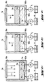
- the exemplary embodiment of the device according to the invention shown in FIGS. 1A-C is designed for the production of contact lenses from a liquid starting material which can be polymerized or crosslinked, for example, by UV radiation.
- 1A shows the shape 1 in the closed state.
- the mold 1 is arranged in a container 10 which is filled with uncrosslinked liquid starting material M.
- the device comprises an energy source in the form of a UV light source 2a and Means 2b, which direct the energy provided by the UV light source 2a in the form of a parallel beam 3 onto the mold 1.
- These means 2a can in particular also comprise an aperture which is arranged between the UV light source 2a and the container 10.
- the UV light source 2a and the means 2b can be combined into a single unit.
- the mold 1 comprises two mold halves 11 and 12, each having a curved mold surface 13 or 14, which together define a mold cavity 15, which in turn determines the shape of the contact lens CL to be produced.
- the shaped surface 13 of the upper mold half 11 is concave and defines the front surface with the adjoining edge area.
- This mold half 11 is usually referred to as the mother mold half.
- the molding surface 14 of the lower mold half 12 is convex and determines the rear or base surface of the contact lens CL and the adjoining edge region thereof.
- This mold half 12 is usually referred to as the father mold half.
- the mold cavity is not completely and tightly sealed, but in the exemplary embodiment shown they are in the region of their peripheral edge which is the edge of the part to be produced Contact lens CL defined, open all around.
- the mold cavity 15 is also connected to a relatively narrow annular gap 16, as is also the case with the molds shown in US Pat. No. 4,113,224.
- the annular gap 16 is delimited by a flat mold wall 17 and 18 on the mother mold half 11 and the father mold half 12, respectively.
- spacer means in the form of spacer bolts 19 are provided on the male mold half 12, which keep the female mold half 11 at a distance, that is to say prevent the mold from being fully closed and thus define the annular gap 16.
- the spacer bolts can be adjustable (for example by means of a thread (not shown) embedded in the male mold half), they can also be designed to be resilient. In this way By adjusting the distance means or against a spring force, the two mold halves 11 and 12 can be moved towards one another during the crosslinking process in order to compensate for shrinkage.
- the shape can, of course, be opened and closed in the usual way, for example by means of a closing unit indicated only by the arrow 1a.
- the distance between the two mold halves for the shrinkage compensation can also be adjusted, for example, by means of this external closing unit.
- the two mold halves 11 and 12 consist of a material that is as permeable as possible for the selected energy, here as mentioned, for example, UV light, for example polypropylene or another polyolefin that is usually used for such purposes. Since the irradiation with UV light takes place here only from one side, from above, only the upper one, that is to say the mother mold half 11, needs to be UV-transparent. The same applies, of course, to the radiation from below through the male mold half 12. According to a particularly expedient and advantageous embodiment of the invention, at least the mold half irradiated by UV light consists of quartz. This material not only has a particularly good UV permeability, but is also very hard and resistant, so that molds made from this material can be reused very well.
- UV light for example polypropylene or another polyolefin that is usually used for such purposes. Since the irradiation with UV light takes place here only from one side, from above, only the upper one, that is to say the mother mold half 11, needs to be UV-transparent
- the prerequisite for this is that the mold is either closed without power or not completely, so that the mold halves are not damaged by contact.
- quartz UV-permeable special glasses or sapphire can also be used. Due to the reusability of the mold or mold halves, a relatively high level of effort can be expended in order to obtain molds with extremely high precision and reproducibility. Since the mold halves do not touch each other in the area of the lens to be produced, that is to say in the area of the mold cavity 15 or the actual mold surfaces, damage by contact is excluded. This ensures a long tool life. This also has favorable consequences for the reproducibility of the contact lenses or molded articles to be produced in general.
- the space between the two mold halves 11 and 12 and thus also the mold cavity 15 is arranged in the uncrosslinked starting material M during the entire production process.
- at least the mold cavity is completely arranged in the starting material which is in the uncrosslinked state when it is filled. 1B that the upper mold half 11 does not protrude completely from the starting material M even in the open state, the space between the mold halves 11 and 12 always remains below the liquid level of the starting material M located in the container 10.
- the space is between the two mold halves and in particular the mold cavity with the starting material M located in the container 10 constantly in connection. At no time can air get into the space between the two mold halves 11 and 12.
- UV rays 3 are applied to it and crosslinking of the molded body is achieved.
- the mold is opened and the molded body in the form of the contact lens CL is removed from the mold, that is to say it is removed from the mold and removed from the mold.
- the gripping device 4 is symbolically provided in FIG. 1C, which, when the upper mold half is lifted off, removes the contact lens CL from the male mold half 12 (FIG. 1B) and removes it from the mold (FIG. 1C).
- the demolding and removal of the contact lens or the molded body from the mold can, however, also be carried out in a different way, as will be explained with reference to the other exemplary embodiments.
- the mold can now be closed again and a new contact lens CL can be produced.
- the exposure to the mold with UV rays is additionally limited to the material in the mold cavity 15, ie only the material in the mold cavity 15 is crosslinked.
- the starting material in the annular gap 16, which surrounds the mold cavity 15, and the rest of the starting material M located in the container 10 are not subjected to energy and are not crosslinked.
- the mold cavity is understood here to mean that cavity of the closed mold which is defined by the complete contour of the molded body to be produced, in particular the contact lens CL.
- the annular gap 16 opening into the mold cavity therefore does not belong to the mold cavity 15 here.
- a mask 21 is provided on the mold wall 17 in the area of the annular gap 16 in the region of the annular gap 16 for the practical implementation, which mask is impermeable (or at least poorly permeable in comparison to the permeability of the mold) extends directly to the mold cavity and, with the exception of the mold cavity, shields all other parts, cavities or surfaces of the mold which are or may come in contact with the liquid, uncrosslinked, possibly excess material, from the radiated energy. Partial areas of the lens edge are not formed by a limitation of the material by means of mold walls, but by a spatial limitation of the radiation or other energy which triggers the polymerization or crosslinking.
- the side walls of the upper mold half are also provided with the mask 21 in order to prevent the starting material M which surrounds the mold in the container 10 from being crosslinked.
- the mask can preferably be a thin chromium layer, which can be produced by methods such as are known, for example, in photo or UV lithography. Other metals or metal oxides may also be considered as mask material.
- the mask can also be coated with a protective layer, in the case of quartz as material for the mold or mold half, for example made of silicon dioxide.
- the mask does not necessarily have to be arranged in a fixed manner; for example, it could also be designed to be removable or replaceable. In principle, it could be provided anywhere on or on the mold, as long as it can only fulfill the function intended for it, namely the shielding of all mold areas which carry no crosslinked material, with the exception of the mold cavity.
- the mask is preferably arranged on a wall surface in contact with the uncrosslinked starting material or just below it, since undesired diffraction and scattering effects can be largely ruled out in this way.
- a mask or masking in or on the mold can even be dispensed with if it is possible in another way to limit the application of energy locally to the mold cavity, taking into account the optical effect of the mold.
- this could be achieved, for example, by a spatially limited light source, a suitable lens arrangement, possibly in combination with external masks, diaphragms or the like, and taking into account the optical effect of the shape.
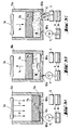
- FIGS. 2A-C Another embodiment of the device according to the invention is shown in FIGS. 2A-C.
- the one mold half here the father mold half
- the container 10a there is also a piston-like displaceable molded part 11a, which can be moved sealingly away from the opposite container wall, here the container bottom 100a, and back onto the container bottom along the side walls of the container. In this way, the mold can be opened and closed.
- the molded part 11a is correspondingly designed on its surface 17a facing the container bottom as a mother mold half.
- Container bottom 100a and mold surface 17a define the mold cavity 15a when the mold is closed (FIG. 2A).
- the molded part does not necessarily have to be piston-like, a membrane could also be provided to which the molded half is attached. Other forms of volume change are also conceivable.
- an inlet 101a is provided, through which starting material can flow into the space between the molded part 11a and the container base 100a.
- the space between the molded part 11a and the container base 100a is in constant contact with a reservoir R.
- pumps P1 and P2 at the inlet 101a or at the outlet 102a starting material can be supplied or fed into the space between the molded part 11a and the container base 100a . It is important that the space between the molded part 11a and the container bottom 100a is always filled with starting material M, so that no air can enter this space.
- the pumps P1 and P2 are shown with an integrated non-return valve, but pumps without an integrated non-return valve can also be used and this can be switched separately between the pump and the tank or, depending on the type of pump, such a non-return valve can also be dispensed with entirely.
- the piston-like displaceable molded part 11a is then moved downwards again and the material located between the molded part 11a and the container bottom 100a is discharged through the outlet 102a (FIG. 2C).
- the material can be removed by means of the pump P2 provided at the outlet.
- the piston-like displaceable molded part 11a is driven only by the liquid starting material that is supplied or removed between the molded part 11a and the container bottom 100a, so that the pumps P1 and P2 provide the drive energy necessary for this. It is also conceivable that no pumps are provided at all and the piston-like displaceable molded part 11a is mechanically driven, that is to say that starting material is sucked in during the upward movement and starting material is pressed out again during the downward movement. Combinations with pumps and a mechanical drive are of course also possible.
- a mask 21a is provided on the molded part 11a. 1A-C, it extends over the annular gap 16a up to the mold cavity 15a, and optionally along the side walls of the piston-like displaceable molded part 11a. If UV radiation 3 is now applied to the mold, crosslinking and thus the formation of the molded body take place in the region of the mold cavity 15a and only there. The material in the other areas, in particular in the annular gap 16a and other starting material in the container 10a, are not crosslinked. For the materials as well as the production and application of such masks, the same considerations apply, which already apply to the explanations of the 1A-C have been made.
- FIGS. 3A-C show an embodiment of the device which is in principle very similar to the embodiment of FIGS. 2A-C.
- the outlet 102a is designed as a deformable tab or plate or as a flap.
- the demolding of the molded body that is to say here the contact lens CL, will be dealt with in the following.
- the mold cavity 15a is filled analogously to the exemplary embodiment according to FIGS. 2A-C by means of the pump P1. If the mold is closed (FIG. 3A), the contact lens CL is produced by crosslinking by applying UV radiation 3 to the mold.
- liquid starting material flows into the container 10a between the container base 100a and the piston-like displaceable molded part 11a.
- the inlet 101a can be designed as a nozzle or a similarly acting flow-generating means.
- the crosslinked contact lens CL is then lifted from the mold by the generated flow and, with a corresponding arrangement of the nozzle, rinsed in the direction of the outlet 102a. This is designed as a deformable tab or plate.
- the tab is deformed downward by the pressure generated and releases the outlet 102a, so that the liquid starting material together with the contact lens CL can be rinsed out through the outlet 102a.
- the contact lens can be collected in a sieve S which is permeable to the liquid starting material.
- the starting material can, for example, be recycled and reused, if necessary after cleaning the same. While the contact lens has been rinsed out, the mold cavity 15a has been filled with new starting material, so that a new contact lens CL can be crosslinked by exposure to UV radiation 3.
- the contact lens can be produced in a first cycle (“production cycle”), that is to say that the piston-like molded part 11a is moved upward, liquid starting material flows between molded part 11a and container bottom 100a, and then moves the molded part 11a downward again becomes.
- production cycle a first cycle
- UV radiation 3 is then applied to the mold, as a result of which crosslinking takes place and the contact lens CL is thus produced.
- the contact lens can now be rinsed out of the mold in a separate second cycle (“rinsing cycle”) without a new contact lens being produced in this second cycle, while a new contact lens CL is produced again in the “one-cycle” device.
- both liquid starting material can be used for rinsing in the "two-cycle” device, but in particular a separate cleaning liquid can also be used.
- This is advantageous in that the shape can then be cleaned particularly well from the inside during the rinsing cycle before starting material flows in again in the next cycle and the next contact lens CL is produced.
- there is therefore both a "one-cycle” operation one contact lens is produced in each cycle
- a "two-cycle” operation a contact lens is produced in the first cycle and in the second Cycle, it is rinsed out and the mold cleaned without making a new contact lens).
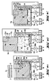
- FIGS. 4A-C Another embodiment of the device according to the invention is shown in FIGS. 4A-C.
- this exemplary embodiment is also similar to the exemplary embodiments described with reference to FIGS. 2A-C and 3A-C, but differs significantly from them in that it comprises a somewhat differently shaped piston-like displaceable molded part 11b.
- the container 10b is also significantly different in that a bulge or recess 104b is provided in its one side wall 103b, which extends in the direction of the movement of the piston-like molded part 11b.
- a gripping device 4b is arranged in this recess 104b.
- the molded part 11b has an indentation 114b on its outer wall 113b exactly in the area in which the recess 104b is provided in the side wall 103b of the container 11b.
- the molded part 11b furthermore has a channel 115b which can be connected to a vacuum source or pressure source P3.
- the gripping device 4b can also be connected to this vacuum or pressure source P3.
- the production of the contact lens CL by cross-linking by exposure to the form with UV radiation 3 is again carried out in the same manner as has already been described with reference to FIGS. 2A-C and 3A-C.
- the manner in which the contact lens CL is removed from the mold should therefore be dealt with primarily.
- UV radiation 3 is again applied to the mold and the contact lens CL is produced by crosslinking (FIG. 4A).
- starting material is pumped between the molded part 11b and the container bottom 100b by means of the pump P1 and the molded part 11b is moved upward (FIG. 4B).
- the gripping device 4b is now pivoted out of the recess 104b over the contact lens CL.
- the gripping device 4b has a bore in its gripper plate 40b, through which vacuum is now applied by means of the vacuum source P3, so that the contact lens CL is lifted off and sucked against the gripper plate 40b. If the contact lens CL is sucked onto the gripper plate 40b, the gripping device 4b is pivoted back into the recess 104b and the molded part 11b is moved downward again. The liquid starting material located between the molded part 11b and the container bottom 100b is sucked off by means of the pump P2 (FIG. 4C).
- the gripping device 4b located in the recess 104b either slides along the outer wall 113b of the molded part 11b or is held in the recess 104b until the gripper plate 40b is located on the outer wall of the molded part 11b opposite the indentation 114b. At this time, excess pressure is applied through the hole in the gripper plate 40b, so that the contact lens CL detaches from the gripper plate 40b and is placed in the indentation 114b. Vacuum is applied through the channel 115b leading to the indentation 114b at the same time that the contact lens CL is detached from the gripper plate 40b, so that the contact lens CL is simply placed away from the gripper plate 40b into the indentation 114b (FIG. 4A). .
- the indentation 114b of the molded part 11b is outside the container 10b (FIG. 4B). If excess pressure is now applied through the channel 115b, the contact lens CL detaches itself from the indentation 114b and can be fed to further processing.
- the side wall 103b can also extend further upward and can have a further niche into which the contact lens CL can be placed or flushed. This results in an even better guidance of the molded part 11b and protection of its corresponding sealing surfaces which slide along the container wall.
- the pump P3 is provided for the application of overpressure or underpressure, the overpressure connection HP or underpressure connection NP, depending on the position of the piston-like displaceable molded part, being connected to the channel 115b or to the bore in the gripper plate 40b.
- This pump P3 can draw from the reservoir R, in which starting material is provided, starting material with which the required pressure is generated.
- 4A-C show two separate reservoirs at the inlet 101b and at the outlet 102b, into which the pumps P1 or P2 and P3 protrude, but it goes without saying that it is also possible that these are one and is the same reservoir.
- the exemplary embodiment according to FIGS. 4A-C can also operate both as a “one-cycle” device and as a “two-cycle” device.
- the “one cycle” device it must be ensured that only starting material ever flows into the container 10b.
- a cleaning liquid can be supplied in the second cycle, in which the contact lens CL is then also removed.
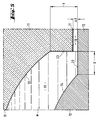
- annular gap 16 which can be seen better in FIG. 5, is selected so far or so high ( ⁇ y) that the two mold halves 11 and 12 come into contact (or the molded part 11, 11a, 11b comes into contact with the container bottom 100, 100a, 100b). is reliably avoided in the area of the mask 21.
- the positioning (spacing) of the two mold halves is carried out by the spacer bolts 19 (Fig. 1A-C).
- the mold cavity 15 in FIG. 5 has a shape that corresponds to the typical edge geometry of a so-called soft contact lens.
- the cavity and thus the contact lens edge is formed here by two wall surfaces 22 and 23 which are at right angles to one another and are formed on the male 12 and female mold halves 11, respectively.
- the width and the height of these two wall surfaces or the edge regions of the contact lens defined by them are designated X and Y respectively.
- the lens edge can of course also be somewhat rounded.
- the wall surface 23 of the mold half 11 does not reach all the way to and the wall surface 22, but is less high by the amount ⁇ y of the annular gap 16.
- Typical gap heights ⁇ y for the manufacture of contact lenses are in the range below about 100 ⁇ m. Tests have shown that, at least when using parallel energy radiation, a clean edge structuring of the molded body to be produced is still possible even at gap heights of approximately 1 mm. Conversely, however, it is also readily possible to reduce the width or height of the annular gap to practically zero if the mold is only closed without force, that is to say the two mold halves lie on one another without external stress.
- the device according to the invention is still distinguished from known devices in that the mold is closed in the starting material and thus the mold can be closed more quickly without the risk of air pockets.
- the mold half facing away from the energy source can in principle be made of any material that is compatible with the crosslinkable or crosslinked material or components thereof. If metals are used, however, depending on the type of energy radiation, potential reflections are to be expected, which may lead to undesired effects such as overexposure, edge distortion or the like. Absorbent materials do not have these disadvantages.
- the device explained with the aid of the figures can also comprise several cavities instead of just one cavity, so that several contact lenses can be produced simultaneously during a cycle.
- This variant is particularly efficient.
- a flow control can be carried out in such a way that the piston-like molded part is first subjected to mechanical force and the starting material is released into the container with a slight delay when it is fed in, or is released from the container with a little delay when it is removed becomes.
- both pumps are used and the piston is mechanically driven.
- a negative pressure can be generated in the container when it is fed in and a positive pressure can be specifically generated in the container or the pressure in the container can generally be influenced in this way.
- a variant is also conceivable in which the number of cycles after which a new contact lens is produced is variable.
- a sensor can detect whether a contact lens has actually been rinsed out of the mold and only if the sensor has detected such a rinsed contact lens is the mold completely closed and a new contact lens is produced. If the sensor has not detected a rinsed contact lens, the mold is rinsed until the contact lens has been rinsed out of the mold.
- the starting material which can be crosslinked by irradiation with UV light is, for example, the HEMA (hydroxyethyl methacrylate) or poly-HEMA which is frequently used for this purpose, in particular in a mixture with a suitable crosslinking agent such as ethylene glycol dimethacrylate.
- HEMA hydroxyethyl methacrylate
- poly-HEMA poly-HEMA which is frequently used for this purpose
- a suitable crosslinking agent such as ethylene glycol dimethacrylate.
- other materials may be used for other shaped bodies, although in principle other forms of energy, e.g. Electron radiation, gamma radiation, thermal energy etc. are possible.
- materials that can be crosslinked under UV light are common, but not essential.
- Special prepolymers are particularly suitable as starting materials, namely in particular those based on polyvinyl alcohol, which contain cyclic acetal groups and crosslinkable groups.
- EP 216,074 discloses contact lenses which contain polyvinyl alcohol which has (meth) acryloyl groups bonded via urethane groups.
- EP 189,375 describes contact lenses made from polyvinyl alcohol crosslinked with polyepoxides.
- EP 201,693 describes, inter alia, acetals of unbranched aldehydes having 2 to 11 carbon atoms which carry an amino group at the end, which amino group is substituted by a C3-C24-olefinically unsaturated organic radical.
- This organic radical has a functionality which withdraws electrons from the nitrogen atom, and the olefinically unsaturated functionality can also be polymerized.
- EP 201,693 also claims reaction products of the acetals characterized above with a 1,2-diol, a 1,3-diol, a polyvinyl alcohol or a cellulose. However, such products are not specifically described.
- the prepolymers contain a 1,3-diol backbone, a certain percentage of the 1,3-diol units being modified to give a 1,3-dioxane, which in the 2-position is not polymerizable has polymerized residue.
- the polymerizable radical is in particular an aminoalkyl radical, to the nitrogen atom of which a polymerizable group is bonded.
- the prepolymer according to the invention is preferably a derivative of a polyvinyl alcohol with a molecular weight of at least about 2000, that of about 0.5 to about 80%, based on the number of hydroxyl groups of the polyvinyl alcohol, contains units of the formula I, wherein R is lower alkylene having up to 8 carbon atoms, R1 is hydrogen or lower alkyl and R2 is an olefinically unsaturated, electron-withdrawing, copolymerizable radical having preferably up to 25 carbon atoms.
- R2 is, for example, an olefinically unsaturated acyl radical of the formula R3-CO-, in which R3 is an olefinically unsaturated copolymerizable radical having 2 to 24 carbon atoms, preferably having 2 to 8 carbon atoms, particularly preferably having 2 to 4 carbon atoms.
- the R2 radical is a radical of the formula II -CO-NH- (R4-NH-CO-O) q -R5-O-CO-R3 (II) wherein q is zero or one and R4 and R5 independently of one another lower alkylene with 2 to 8 carbon atoms, arylene with 6 to 12 carbon atoms, a saturated bivalent cycloaliphatic group with 6 to 10 carbon atoms, arylenealkylene or alkylene arylene with 7 to 14 carbon atoms or arylenealkylene arylene with 13 mean up to 16 carbon atoms and wherein R3 has the meaning given above.
- the prepolymer according to the invention is therefore in particular a derivative of a polyvinyl alcohol with a molecular weight of at least about 2000, which contains from about 0.5 to about 80%, based on the number of hydroxyl groups of the polyvinyl alcohol, of units of the formula III, where R is lower alkylene, R1 is hydrogen or lower alkyl, p is zero or one, q is zero or one, R3 is an olefinically unsaturated copolymerizable radical having 2 to 8 carbon atoms and R4 and R5 are independently lower alkylene having 2 to 8 carbon atoms, arylene with 6 to 12 carbon atoms, a saturated bivalent cycloaliphatic group with 6 to 10 carbon atoms, arylene alkylene or alkylene arylene with 7 to 14 carbon atoms or arylene alkylene arylene with 13 to 16 carbon atoms.
- Lower alkylene R preferably has up to 8 carbon atoms and can be straight-chain or branched. Suitable examples include octylene, hexylene, pentylene, butylene, propylene, ethylene, methylene, 2-propylene, 2-butylene or 3-pentylene. Lower alkylene R preferably has up to 6 and particularly preferably up to 4 carbon atoms. The meanings methylene and butylene are particularly preferred.
- R1 is preferably hydrogen or lower alkyl having up to seven, especially up to four carbon atoms, especially hydrogen.
- Lower alkylene R4 or R5 preferably has 2 to 6 carbon atoms and is in particular straight-chain. Suitable examples include propylene, butylene, hexylene, dimethylethylene and, particularly preferably, ethylene.
- Arylene R4 or R5 is preferably phenylene which is unsubstituted or substituted by lower alkyl or lower alkoxy, in particular 1,3-phenylene or 1,4-phenylene or methyl-1,4-phenylene.
- a saturated bivalent cycloaliphatic group R4 or R5 is preferably cyclohexylene or cyclohexylene-lower alkylene, for example cyclohexylene methylene, which is unsubstituted or substituted by one or more methyl groups, such as for example trimethylcyclohexylene methylene, for example the bivalent isophorone radical.
- the arylene unit of alkylene arylene or arylene alkylene R4 or R5 is preferably phenylene, unsubstituted or substituted by lower alkyl or lower alkoxy, the alkylene unit thereof is preferably lower alkylene, such as methylene or ethylene, especially methylene.
- Such radicals R4 or R5 are therefore preferably phenylene methylene or methylene phenylene.
- Arylenealkylenearylene R4 or R5 is preferably phenylene-lower alkylene-phenylene with up to 4 carbon atoms in the alkylene unit, e.g. Phenylene ethylene phenylene.
- the radicals R4 and R5 independently of one another are preferably lower alkylene having 2 to 6 carbon atoms, phenylene, unsubstituted or substituted by lower alkyl, cyclohexylene or cyclohexylene-lower alkylene, unsubstituted or substituted by lower alkyl, phenylene-lower alkylene, lower alkylene-phenylene or phenylene-lower alkylene-phenylene.
- lower means, in the context of radicals and compounds, unless defined otherwise, radicals or compounds having up to 7 carbon atoms, preferably having up to 4 carbon atoms.
- Lower alkyl in particular has up to 7 carbon atoms, preferably up to 4 carbon atoms, and is e.g. Methyl, ethyl, propyl, butyl or tert-butyl.
- Lower alkoxy in particular has up to 7 carbon atoms, preferably up to 4 carbon atoms, and is e.g. Methoxy, ethoxy, propoxy, butoxy or tert-butoxy.
- the olefinically unsaturated copolymerizable radical R 3 having 2 to 24 carbon atoms preferably means alkenyl having 2 to 24 carbon atoms, in particular alkenyl having 2 to 8 carbon atoms and particularly preferably alkenyl having 2 to 4 carbon atoms, for example ethenyl, 2-propenyl, 3-propenyl, 2- Butenyl, hexenyl, octenyl or dodecenyl.
- the meanings ethenyl and 2-propenyl are preferred, so that the group -CO-R3 stands for the acyl radical of acrylic acid or methacrylic acid.
- the bivalent group -R4-NH-CO-O- is present when q is one and absent when q is zero. Prepolymers in which q is zero are preferred.
- the bivalent group -CO-NH- (R4-NH-CO-O) q -R5-O- is present when p is one and absent when p is zero.
- Prepolymers in which p is zero are preferred.
- the index q preferably means zero.
- Prepolymers in which p is one, the index q is zero and R5 is lower alkylene are particularly preferred.
- a preferred prepolymer according to the invention is therefore in particular a derivative of a polyvinyl alcohol with a molecular weight of at least about 2000, which contains from about 0.5 to about 80%, based on the number of hydroxyl groups of the polyvinyl alcohol, of units of the formula m, in which R represents lower alkylene having up to 6 carbon atoms, p is zero and R3 is alkenyl having 2 to 8 carbon atoms.
- a further preferred prepolymer according to the invention is therefore, in particular, a derivative of a polyvinyl alcohol with a molecular weight of at least about 2000, which contains from about 0.5 to about 80%, based on the number of hydroxyl groups of the polyvinyl alcohol, of units of the formula III in which R is lower alkylene with up to 6 carbon atoms, p is one, q is zero, R5 is lower alkylene with 2 to 6 carbon atoms and R3 is alkenyl with 2 to 8 carbon atoms.
- a further preferred prepolymer according to the invention is therefore, in particular, a derivative of a polyvinyl alcohol with a molecular weight of at least about 2000, which contains from about 0.5 to about 80%, based on the number of hydroxyl groups of the polyvinyl alcohol, of units of the formula III in which R is lower alkylene with up to 6 carbon atoms, p is one, q one is, R4 is lower alkylene with 2 to 6 carbon atoms, phenylene, unsubstituted or substituted by lower alkyl, cyclohexylene or cyclohexylene-lower alkylene, unsubstituted or substituted by lower alkyl, phenylene-lower alkylene , Lower alkylene-phenylene or phenylene-lower alkylene-phenylene, R5 is lower alkylene having 2 to 6 carbon atoms and R3 is alkenyl having 2 to 8 carbon atoms.
- the prepolymers according to the invention are derivatives of polyvinyl alcohol with a Molecular weight of at least about 2000, which contains from about 0.5 to about 80%, based on the number of hydroxyl groups of the polyvinyl alcohol, of units of the formula III, in particular about 1 to 50%, more preferably about 1 to 25%, preferably about 2 to 15% and particularly preferably about 3 to 10%.
- Prepolymers according to the invention which are intended for the production of contact lenses contain in particular from about 0.5 to about 25%, based on the number of hydroxyl groups of the polyvinyl alcohol, of units of the formula III, in particular about 1 to 15% and particularly preferably about 2 to 12%.
- Polyvinyl alcohols which can be derivatized according to the invention preferably have a molecular weight of at least 10,000.
- the upper limit of the polyvinyl alcohols can have a molecular weight of up to 1,000,000.
- the polyvinyl alcohols preferably have a molecular weight of up to 300,000, in particular up to about 100,000 and very particularly preferably up to about 50,000.
- Polyvinyl alcohols suitable according to the invention usually have a poly (2-hydroxy) ethylene structure.
- the polyvinyl alcohols derivatized according to the invention can also have hydroxyl groups in the form of 1,2-glycols, such as copolymer units of 1,2-dihydroxyethylene, as can be obtained, for example, by alkaline hydrolysis of vinyl acetate-vinylene carbonate copolymers.
- polyvinyl alcohols derivatized according to the invention can also contain small amounts, for example up to 20%, preferably up to 5%, of copolymer units of ethylene, propylene, acrylamide, methacrylamide, dimethacrylamide, hydroxyethyl methacrylate, methyl methacrylate, methyl acrylate, ethyl acrylate, vinyl pyrrolidone, hydroxyethyl acrylate, allyl alcohol, allyl alcohol or similar comonomers commonly used.
- small amounts for example up to 20%, preferably up to 5%, of copolymer units of ethylene, propylene, acrylamide, methacrylamide, dimethacrylamide, hydroxyethyl methacrylate, methyl methacrylate, methyl acrylate, ethyl acrylate, vinyl pyrrolidone, hydroxyethyl acrylate, allyl alcohol, allyl alcohol or similar comonomers commonly used.
- Other manufacturers are e.g. Nippon Gohsei (Gohsenol®), Monsanto (Gelvatol®), Wacker (Polyviol®) or the Japanese manufacturers Kuraray, Denki and Shin-Etsu.
- copolymers of hydrolyzed vinyl acetate can also be used are available, for example, as hydrolyzed ethylene-vinyl acetate (EVA), or vinyl chloride-vinyl acetate, N-vinylpyrrolidone-vinyl acetate and maleic anhydride-vinyl acetate.
- EVA hydrolyzed ethylene-vinyl acetate
- vinyl chloride-vinyl acetate vinyl chloride-vinyl acetate
- N-vinylpyrrolidone-vinyl acetate N-vinylpyrrolidone-vinyl acetate
- maleic anhydride-vinyl acetate maleic anhydride-vinyl acetate
- Polyvinyl alcohol is usually produced by hydrolysis of the corresponding homopolymeric polyvinyl acetate.
- the polyvinyl alcohol derivatized according to the invention contains less than 50% polyvinyl acetate units, in particular less than 20% polyvinyl acetate units.
- the compounds containing units of the formula III can be prepared in a manner known per se.
- a polyvinyl alcohol with a molecular weight of at least about 2000 which contains units of the formula IV with a compound of the formula VI are implemented in which the variables are as defined for the compound of formula V, in particular under acidic conditions, and the cyclic acetal obtainable in this way is then reacted with a compound of formula VII OCN- (R4-NH-CO-O) q -R5-O-CO-R3 (VII) where the variables are as defined for the compound of formula V.
- reaction product of a compound of formula IV and a compound of formula VI as described above can be obtained with a compound of formula (VIII)
- X-CO-R3 (VIII) are implemented in which R3 is, for example, alkenyl having 2 to 8 carbon atoms and X is a reactive group, for example etherified or esterified hydroxy, for example halogen, in particular chlorine.
- Compounds of the formula V in which p is zero are known, for example, from EP 201,693.
- Compounds of the formula VI are also described there.
- Compounds of the formula VII are known per se or can be prepared in a manner known per se.
- An example of a compound of formula VII in which q is zero is isocyanatoethyl methacrylate.
- An example of a compound of formula VII in which q represents one is the reaction product of isophorone diisocyanate with 0.5 equivalents of hydroxyethyl methacrylate.
- Compounds of formula VIII are known per se, a typical representative is methacryloyl chloride.
- the prepolymers of the formula I and III are extremely stable. This is unexpected for the person skilled in the art because, for example, more highly functional acrylates usually have to be stabilized. If such compounds are not stabilized, rapid polymerization usually occurs. However, spontaneous crosslinking by homopolymerization does not take place with the prepolymers according to the invention.
- the prepolymers of the formula I or III can moreover be purified in a manner known per se, for example by precipitation with acetone, dialysis or ultrafiltration, with ultrafiltration being particularly preferred. This cleaning process enables the prepolymers of the formula I or III to be used in extremely pure form, e.g. are obtained as concentrated aqueous solutions which are free or at least substantially free of reaction products such as salts and of starting materials such as e.g. Compounds of formula V or other non-polymeric ingredients.
- the preferred cleaning process of the prepolymers according to the invention can be carried out in a manner known per se. It is possible to carry out the ultrafiltration repeatedly, for example two to ten times. Alternatively, the ultrafiltration can also be carried out continuously until the desired degree of purity is reached.
- the desired degree of purity can in principle be chosen as high as desired.
- a suitable measure of the degree of purity is e.g. the saline content of the solution, which can be easily determined in a known manner.
- the prepolymers of the formula I or III according to the invention can be crosslinked in an extremely effective manner and in a targeted manner, in particular by photocrosslinking.
- a photoinitiator which can initiate radical crosslinking is suitably added.
- these are familiar to the person skilled in the art; in particular, benzoin methyl ether, 1-hydroxycyclohexylphenyl ketone, Daracure 1173 or Irgacure types can be mentioned as suitable photoinitiators.
- the crosslinking can then be triggered by actinic radiation, such as UV light, or ionizing radiation, such as gamma radiation or X-rays.
- the photopolymerization is suitably carried out in a solvent.
- solvents which dissolve polyvinyl alcohol and any vinyl comonomers additionally used are suitable as solvents, e.g. Water, alcohols such as lower alkanols, e.g. Ethanol or methanol, also carboxamides, such as dimethylformamide or dimethyl sulfoxide, as well as mixtures of suitable solvents, such as e.g. Mixtures of water with an alcohol, e.g. a water / ethanol or water / methanol mixture.
- the photocrosslinking is preferably carried out directly from an aqueous solution of the prepolymers according to the invention, which can be obtained as a result of the preferred cleaning step, an ultrafiltration, if appropriate after adding an additional vinyl comonomer.
- an aqueous solution of the prepolymers according to the invention which can be obtained as a result of the preferred cleaning step, an ultrafiltration, if appropriate after adding an additional vinyl comonomer.
- the photocrosslinking of an approximately 15 to 40% aqueous solution can be carried out.
- the process for the preparation of the polymers according to the invention can be characterized, for example, by the fact that a prepolymer containing units of the formula I or III, in particular in essentially pure form, i.e. for example after single or multiple ultrafiltration, preferably in solution, in particular in aqueous solution, in the absence or presence of an additional vinyl comonomer, photocrosslinked.
- the vinylic comonomer which can additionally be used in the photocrosslinking according to the invention can be hydrophilic, hydrophobic or a mixture of a hydrophobic and a hydrophilic vinylic monomer.
- Suitable vinylic monomers include, in particular, those commonly used in the manufacture of contact lenses.
- a hydrophilic vinyl monomer is understood to mean a monomer which, as a homopolymer, typically gives a polymer which is water-soluble or can absorb at least 10% by weight of water.
- a hydrophobic vinyl monomer is understood to mean a monomer which, as a homopolymer, typically results in a polymer which is water-insoluble and can absorb less than 10% by weight of water.
- the crosslinked ones contain Polymers according to the invention preferably between about 1 and 15 percent, particularly preferably between about 3 and 8 percent, units of the formula I or III, based on the number of hydroxyl groups of the polyvinyl alcohol, which are reacted with about 0.1 to 80 units of the vinyl monomer.
- the proportion of the vinyl comonomers, if used, is preferably 0.5 to 80 units per unit of the formula I, in particular 1 to 30 units of vinyl comonomer per unit of the formula I and particularly preferably 5 to 20 units per unit of the formula I.
- hydrophobic vinylic comonomer or a mixture of a hydrophobic vinylic comonomer with a hydrophilic vinylic comonomer, this mixture containing at least 50% by weight of a hydrophobic vinylic comonomer.
- this mixture containing at least 50% by weight of a hydrophobic vinylic comonomer.
- Suitable hydrophobic vinyl comonomers include, without this list being exhaustive, C1-C18 alkyl acrylates and methacrylates, C3-C18 alkyl acrylamides and methacrylamides, acrylonitrile, methacrylonitrile, vinyl C1-C18 alkanoates, C2-C18 alkenes, C2 -C18-haloalkenes, styrene, C1-C6-alkylstyrene, vinyl alkyl ethers in which the alkyl part has 1 to 6 carbon atoms, C2-C10-perfluoroalkyl-acrylates and methacrylates or correspondingly partially fluorinated acrylates and methacrylates, C3-C12-perfluoroalkyl-ethylthiocarbonylaminoethyl -acrylates and -methacrylates, acryloxy and methacryloxy-alkylsiloxanes, N-vinylcarbazole,
- Suitable hydrophobic vinyl comonomers include methyl acrylate, ethyl acrylate, propyl acrylate, isopropyl acrylate, cyclohexyl acrylate, 2-ethylhexyl acrylate, methyl methacrylate, ethyl methacrylate, propyl methacrylate, vinyl acetate, vinyl propionate, vinyl buryrate, vinyl valerate, vinyl chloride, vinyl chloride, vinyl chloride, vinyl chloride 1-butene, butadiene, methacrylonitrile, vinyl toluene, vinyl ethyl ether, perfluorohexylethyl thiocarbonylaminoethyl methacrylate, isobornyl methacrylate, trifluoromethyl methacrylate, hexafluoroisopropyl methacrylate, hexafluorobutyl methacrylate, tris-trimethylsilyloxy-silylpropy
- Suitable hydrophilic vinyl comonomers include, without this list being exhaustive, hydroxy-substituted lower alkyl acrylates and methacrylates, acrylamide, methacrylamide, lower alkyl acrylamides and methacrylamides, ethoxylated acrylates and methacrylates, hydroxy-substituted lower alkyl acrylamides and methacrylamides, hydroxy-substituted lower alkylsulfonate ether, sodium ethylsulfonyl vinyl sulfonate , 2-acrylamido-2-methylpropanesulfonic acid, N-vinylpyrrole, N-vinylsuccinimide, N-vinylpyrrolidone, 2- or 4-vinylpyridine, acrylic acid, methacrylic acid, amino- (where the term "amino" also includes quaternary ammonium), mono-lower alkylamino or Diniederalkylamino-lower alkyl
- hydrophilic vinyl comonomers examples include hydroxyethyl methacrylate, hydroxyethyl acrylate, acrylamide, methacrylamide, dimethylacrylamide, allyl alcohol, vinyl pyridine, vinyl pyrrolidone, glycerol methacrylate, N- (1,1-dimethyl-3-oxobutyl) acrylamide, and the like.
- Preferred hydrophobic vinyl comonomers are methyl methacrylate and vinyl acetate.
- Preferred hydrophilic vinyl comonomers are 2-hydroxyethyl methacrylate, N-vinyl pyrrolidone and acrylamide.
- aminoacetaldehyde dimethylacetal 52.6 g are dissolved in 150 ml of deionized water and cooled to 5 ° C. with ice cooling. Subsequently, 50 ml of methacrylic acid chloride and 50 ml of 30% sodium hydroxide solution are simultaneously added over 40 minutes in such a way that the pH remains at 10 and the temperature does not rise above 20 ° C. After the addition has ended, the remaining content of aminoacetaldehyde dimethylacetal is determined to be 0.18% by means of gas chromatography. The amine is completely converted by further addition of 2.2 ml of methacrylic acid chloride and 2.0 ml of 30% sodium hydroxide solution.
- the aqueous phase is extracted with 50 ml of petroleum ether and washed with water.
- the petroleum ether phase contains 3.4 g of by-product.
- the water phases are combined and give 402.8 g of a 20.6% solution of methacrylamidoacetaldehyde dimethylacetal.
- the product is 98.2% pure according to the gas chromatogram.
- the solution is concentrated. 660 g of a 17.9% solution of methacrylamidoacetaldehydo-1,3-acetal of polyvinyl alcohol with a viscosity of 210 cp are obtained.
- the inherent viscosity of the polymer is 0.319.
- the nitrogen content is 0.96%.
- 11 mol% of the OH groups are acetalized and 5 mol% of the OH groups are acetylated.
- a 30.8% solution with a viscosity of 3699 cp is obtained.
- the 30.8% polymer solution according to Example 4 with a viscosity of about 3600 cp is mixed with 0.7% Darocur 1173 (based on the polymer content).
- the solution is filled into a transparent polypropylene contact lens mold, the mold is closed.
- the solution is exposed for 6 seconds from a distance of 18 cm using a 200 watt Oriel UV lamp.
- the mold opens and the finished contact lens can be removed.
- the contact lens is transparent and has a water content of 61%.
- the modulus is 0.9 mPa, the elongation at break is 50%.
- the contact lens is autoclaved at 121 ° C for 40 minutes. No changes in shape can be detected on a contact lens treated in this way.
- Example 10.00 g of a 27.1% polymer solution according to Example 7 are mixed with 0.0268 g Darocur 1173 (0.7% based on the polymer content) and 0.922 g methyl methacrylate. After adding 2.3 g of methanol, a clear solution is obtained. As in Example 8, this solution is exposed to a 200 watt oral lamp for a period of 14 seconds. A transparent contact lens with a water content of 70.4% is obtained.
- the polymers according to the invention can be processed to shaped articles in a manner known per se, in particular to contact lenses, for example by photocrosslinking the prepolymers according to the invention in contact lens forms in the manner described in detail above.
- shaped articles according to the invention in addition to contact lenses, are biomedical or especially ophthalmic shaped articles, e.g. Intraocular lenses, eye bandages, molded articles that can be used in surgery, such as heart valves, artificial arteries or the like, as well as films or membranes, e.g. Membranes for diffusion control, photostructurable films for information storage, or photoresist materials, e.g. Membranes or moldings for etching resist or screen printing resist.
- ophthalmic shaped articles e.g. Intraocular lenses, eye bandages, molded articles that can be used in surgery, such as heart valves, artificial arteries or the like, as well as films or membranes, e.g. Membranes for diffusion control, photostructurable films for information
- Contact lenses which comprise a polymer according to the invention as described above or which consist essentially or entirely of such a polymer have a range of unusual and extremely advantageous properties. These properties include, for example, their excellent compatibility with the human cornea, which are based on a balanced ratio of water content, oxygen permeability and mechanical properties. For the rest, the contact lenses according to the invention have high dimensional stability. Even after autoclaving with e.g. around 120 ° C no changes in shape can be detected.
- such contact lenses can be produced in a very simple and efficient manner compared to the prior art. This is due to several factors.
- the starting materials can be procured or manufactured inexpensively.
- the prepolymers are surprisingly stable, so that they can be subjected to high-level cleaning.
- a material can therefore be used for crosslinking which practically no longer requires subsequent cleaning, such as in particular a complex extraction of unpolymerized components.
- the polymerization can also be carried out in aqueous solution, so that a subsequent hydration step is not necessary.
- the photopolymerization takes place within a short time, so that the manufacturing process of the contact lenses according to the invention can also be designed extremely economically from this point of view.
- the moldings according to the invention are particularly suitable as mass articles, such as, for example, as contact lenses which are worn for a short period of time and are then replaced by new lenses.
Abstract
Description
Die Erfindung betrifft ein Verfahren zur Herstellung von Formkörpern, insbesondere optischen Linsen und speziell Kontaktlinsen, gemäss dem Oberbegriff des jeweiligen unabhängigen Patentanspruchs. Ausserdem betrifft die Erfindung nach dem Verfahren bzw. mit der Vorrichtung hergestellte Formkörper, insbesondere optische Linsen und speziell Kontaktlinsen.The invention relates to a method for producing molded articles, in particular optical lenses and especially contact lenses, according to the preamble of the respective independent patent claim. In addition, the invention relates to moldings produced by the method or by the device, in particular optical lenses and especially contact lenses.
Kontaktlinsen, welche in grossen Stückzahlen wirtschaftlich herzustellen sind, werden bevorzugt nach sogenannten Mould- Verfahren und speziell nach dem Full-Mold-Verfahren gefertigt. Bei diesen Verfahren werden die Linsen zwischen üblicherweise zwei Formhälften (Moulds) in ihrer endgültigen Form hergestellt, so dass weder eine nachträgliche Bearbeitung der Oberflächen der Linsen noch eine Bearbeitung des Randes erforderlich ist. Mould-Verfahren sind beispielsweise aus der WO-A-87/04390 oder aus der EP-A-0,367,513 bekannt.Contact lenses, which can be produced economically in large quantities, are preferably manufactured according to the so-called mold process and especially according to the full mold process. In these processes, the lenses are usually produced in their final shape between two mold halves, so that neither a subsequent processing of the surfaces of the lenses nor a processing of the edge is necessary. Mold processes are known, for example, from WO-A-87/04390 or from EP-A-0,367,513.
Bei diesen bekannten Mould-Verfahren wird die Geometrie der herzustellenden Kontaktlinse durch den Formhohlraum (Formkavität) festgelegt. Der Kontaktlinsenrand wird ebenfalls durch die üblicherweise aus zwei Formhälften bestehende Form gebildet. Die Geometrie des Randes wird durch die Kontur der beiden Formhälften in dem Bereich festgelegt, in dem sie sich berühren.In these known mold processes, the geometry of the contact lens to be produced is determined by the mold cavity (mold cavity). The edge of the contact lens is also formed by the shape usually consisting of two mold halves. The geometry of the edge is determined by the contour of the two mold halves in the area in which they touch.
Zur Herstellung einer Kontaktlinse wird zunächst in die weibliche Formhälfte eine bestimmte Menge eines fliessfähigen Ausgangsmaterials eingebracht. Danach wird die Form durch Aufsetzen der männlichen Formhälfte geschlossen. Normalerweise wird das Ausgangsmaterial etwas überdosiert, so dass die überschüssige Menge beim Schliessen der Form in einen an den Formhohlraum nach aussen sich anschliessenden Überlauf-Raum verdrängt wird. Die anschliessende Polymerisation bzw. Vernetzung des Ausgangsmaterials erfolgt durch Bestrahlung mit UV-Licht bzw. durch Wärmeeinwirkung oder eine andere nicht-thermische Methode. Dabei werden sowohl das Ausgangsmaterial in dem Formhohlraum als auch das überschüssige Material in dem Überlauf-Raum ausgehärtet. Die Aushärtung des überschüssigen Materials kann etwas verzögert erfolgen, da sie anfangs möglicherweise durch Luftsauerstoff inhibiert wird. Um eine fehlerfreie Trennung der Kontaktlinse von dem überschüssigen Material zu erhalten, muss in der Berührungszone der beiden Formhälften eine gute Abdichtung bzw. Verdrängung des überschüssigen Materials erreicht werden. Nur so können fehlerfreie Kontaktlinsenränder erhalten werden.To produce a contact lens, a certain amount of a flowable starting material is first introduced into the female mold half. Then the mold is closed by putting on the male mold half. Normally, the starting material is overdosed a little so that the excess amount is displaced when the mold is closed into an overflow space that adjoins the mold cavity to the outside. The subsequent polymerization or crosslinking of the starting material is carried out by irradiation with UV light or by the action of heat or another non-thermal method. Both the starting material in the mold cavity and the excess material in the overflow space hardened. The curing of the excess material can be delayed somewhat, since it may initially be inhibited by atmospheric oxygen. In order to obtain an error-free separation of the contact lens from the excess material, a good seal or displacement of the excess material must be achieved in the contact zone of the two mold halves. This is the only way to obtain flawless contact lens edges.
Als Materialien für die Formen werden heute bevorzugt Kunststoffe wie beispielsweise Polypropylen verwendet. Die Formen werden durch Spritzgiessen hergestellt und nur einmal verwendet (disposable moulds). Dies liegt zum einen daran, dass die Formen durch das überschüssige Material zum Teil verunreinigt sind, beim Abtrennen der Kontaktlinse beschädigt werden oder sich in Teilbereichen irreversibel verformen.Today, plastics such as polypropylene are preferably used as materials for the molds. The molds are made by injection molding and used only once (disposable molds). On the one hand, this is due to the fact that the molds are partially contaminated by the excess material, are damaged when the contact lens is removed, or are irreversibly deformed in some areas.
Bei den spritzgegossenen Formen ist zusätzlich noch mit Schwankungen in den Abmessungen durch Schwankungen im Herstellungsprozess (Temperaturen, Drücke, Materialeigenschaften) zu rechnen. Zusätzlich kann noch ein Schwund der Formen nach dem Spritzgiessen auftreten. Diese masslichen Veränderungen der Form können zu Schwankungen der Parameter der herzustellenden Kontaktlinse (Scheitelbrechwert, Durchmesser, Basiskurve, Mittendicke, etc.) führen, was zu einer Verschlechterung der Qualität der Linsen und damit zu einer reduzierten Ausbeute führen kann. Bei nicht ausreichender Abdichtung zwischen den Formhälften wird das überschüssige Material nicht sauber abgetrennt, was zur Ausbildung von sogenannten Schwimmhäuten am Kontaktlinsenrand führt. Bei stärkerer Ausprägung kann dieser kosmetische Fehler am Rand der Linse auch zu einer Irritation beim Tragen einer solchen Linse führen, weshalb solche Linsen durch eine Inspektion aussortiert werden müssen.In the case of injection molded molds, fluctuations in the dimensions due to fluctuations in the manufacturing process (temperatures, pressures, material properties) are also to be expected. In addition, mold shrinkage can occur after injection molding. These massive changes in shape can lead to fluctuations in the parameters of the contact lens to be manufactured (apex refractive index, diameter, base curve, central thickness, etc.), which can lead to a deterioration in the quality of the lenses and thus to a reduced yield. If there is insufficient sealing between the mold halves, the excess material is not separated cleanly, which leads to the formation of so-called webbed skin on the edge of the contact lens. If the lens is more pronounced, this cosmetic defect at the edge of the lens can also lead to irritation when wearing such a lens, which is why such lenses have to be sorted out by an inspection.
Insbesondere wegen der Anforderungen an die Qualität des Kontaktlinsenrandes werden die Formen auch nur einmal verwendet, da eine gewisse Deformation der Formen im Kontaktbereich nicht mit Sicherheit auszuschliessen ist.In particular because of the requirements placed on the quality of the edge of the contact lens, the shapes are only used once, since a certain deformation of the shapes in the contact area cannot be ruled out with certainty.
In der US-A-4,113,224 ist ein weiteres Mould-Verfahren für die Herstellung von unter anderem Kontaktlinsen beschrieben. Bei diesem Verfahren wird eine Form verwendet, deren Kavität nicht vollständig abgeschlossen ist, sondern über einen dünnen Ringspalt mit einem die Kavität umschliessenden Reservoir-Kanal (Überlaufrinne) verbunden ist. Über den Ringspalt kann während des Vernetzungsvorgangs Material aus dem Reservoir in die Form-Kavität nachfliessen, um den bei den üblicherweise eingesetzten Linsenmaterialien relativ grossen Volumenssschwund auszugleichen.Another mold process for the production of, inter alia, contact lenses is described in US Pat. No. 4,113,224. In this method, a mold is used whose cavity is not completely closed, but is connected via a thin annular gap to a reservoir channel (overflow channel) surrounding the cavity. During the crosslinking process, material can flow from the reservoir into the mold cavity via the annular gap, around that of those normally used Compensate lens materials relatively large volume loss.
Die Vernetzung des Materials im Reservoir-Kanal kann dabei mittels einer inhibierenden Gasatmosphäre oder durch Abschirmung gegenüber der die Vernetzung bewirkenden Energiestrahlung verhindert werden. Um das Nachfliessen von Material in die Form-Kavität zu gewährleisten, wird zumindest anfänglich das in der Form-Kavität befindliche Material nur in einem zentralen Bereich, der kleiner als der Durchmesser der Form-Kavität ist, mit Strahlung beaufschlagt oder in diesem zentralen Bereich einer stärkeren Strahlungsintensität ausgesetzt als in dem diesen zentralen Bereich umgebenden Randbereich der Form-Kavität. Nachdem die Vernetzung im zentralen Bereich begonnen und bis zu einem gewissen Grad fortgeschritten ist, wird jedoch auch im Randbereich mit dem anschliessenden Ringspalt und das im Reservoirkanal befindliche Material der vollen Strahlung ausgesetzt und vernetzt. Dabei entstehen zwangsläufig die schon weiter oben erwähnten Grate und Schwimmhäute, so dass die mit diesem bekannten Verfahren hergestellten Formkörper bzw. Kontaktlinsen einer Nachbearbeitung bedürfen.The crosslinking of the material in the reservoir channel can be prevented by means of an inhibiting gas atmosphere or by shielding against the energy radiation causing the crosslinking. In order to ensure that material continues to flow into the mold cavity, at least initially the material in the mold cavity is exposed to radiation only in a central region, which is smaller than the diameter of the mold cavity, or in this central region exposed to stronger radiation intensity than in the peripheral region of the mold cavity surrounding this central region. After the networking in the central area has begun and has progressed to a certain degree, however, in the peripheral area with the subsequent annular gap and the material located in the reservoir channel, it is exposed to the full radiation and crosslinked. This inevitably creates the ridges and webs already mentioned above, so that the moldings or contact lenses produced using this known method require reworking.
Ein weiteres Problem bei der Herstellung nach den bisher beschriebenen Verfahren ist, dass es beim Schliessen der Form zu Lufteinschlüssen kommen kann. Lufteinschlüsse in den Linsen haben aber zur Folge, dass die Linsen bei der anschliessenden Inspektion (Qualitätskontrolle) als Ausschuss aussortiert werden. Bisher wird die Form entprechend langsam geschlossen, um ein möglichst vollständiges Entweichen der Luft aus dem Formhohlraum (Formkavität) zu ermöglichen. Dieses vergleichsweise langsame Schliessen der Form nimmt jedoch einen relativ grossen Zeitraum in Anspruch.Another problem with the production according to the processes described so far is that air pockets can occur when the mold is closed. Air inclusions in the lenses mean that the lenses are sorted out as rejects during the subsequent inspection (quality control). So far, the mold has been closed correspondingly slowly in order to allow the air to escape as completely as possible from the mold cavity (mold cavity). However, this comparatively slow closing of the mold takes a relatively long time.
Es ist daher eine Aufgabe der Erfindung, ein Verfahren und eine Vorrichtung der genannten Art zu schaffen, bei dem zum einen die Effizienz gross ist, d.h. die Form effizient genutzt werden kann, und bei dem der Aufwand vergleichsweise gering ist, wobei jedoch immer die Vorgabe besteht, dass der hergestellte Formkörper (z.B. Kontaktlinse) von Lufteinschlüssen frei ist.It is therefore an object of the invention to provide a method and a device of the type mentioned, in which on the one hand the efficiency is high, i.e. the shape can be used efficiently, and the effort is comparatively low, but there is always the requirement that the molded body (e.g. contact lens) is free of air pockets.
Verfahrensmässig wird diese Aufgabe dadurch gelöst, dass das Befüllen der Formkavität in dem in zumindest teilweise noch unvernetztem Zustand befindlichen Ausgangsmaterial erfolgt. Dadurch wird erreicht, dass von vornherein beim Befüllen der Form keine Luft mehr in der Form sein kann, mithin also Lufteinschlüsse gänzlich vermieden werden. Als Folge kann die Form schneller geschlossen und damit effizienter genutzt werden, dies bei gleichzeitig vergleichsweise sehr geringem Aufwand. Im übrigen ist auf diese Weise auch automatisch eine exakte Dosierung der erforderlichen Menge des Ausgangsmaterials gegeben, da die Befüllung im Ausgangsmaterial erfolgt.In terms of the method, this object is achieved in that the mold cavity is filled in the starting material which is at least partially still uncrosslinked. This ensures that no air can be left in the mold from the start when the mold is filled, which means that air inclusions are completely avoided. As a result, the mold can be closed more quickly and thus used more efficiently, with comparatively little effort. The rest of the way, too an exact dosage of the required amount of the starting material is given automatically, since the filling takes place in the starting material.
In einer Variante des Verfahrens kann zum Befüllen der Formkavität diese mit einem sie umgebenden Reservoir in Verbindung gebracht werden, in welchem das Ausgangsmaterial bereitgestellt wird und aus welchem die Formkavität geflutet wird. Dies ist eine Verfahrensvariante mit besonders geringem technischen Aufwand.In a variant of the method, the mold cavity can be filled with a surrounding reservoir, in which the starting material is provided and from which the mold cavity is flooded. This is a process variant with particularly little technical effort.
In einer weiteren Verfahrensvariante wird die Form auch in dem Ausgangsmaterial geschlossen, um das Risiko auszuschliessen, dass während des Schliessvorgangs auf irgendeinem Weg Luft in die Formkavität gelangen kann.In a further variant of the method, the mold is also closed in the starting material in order to exclude the risk that air can get into the mold cavity in any way during the closing process.
In einer weiteren Variante wird eine Form verwendet, die einen Behälter und ein in diesem Behälter kolbenartig verschiebbares Formteil umfasst. Dieses Formteil ist zum Öffnen und Schliessen der Form von der ihm gegenüberliegenden Behälterwand weg und auf diese Behälterwand zu bewegbar. Während des Öffnens der Form wird Ausgangsmaterial zwischen Behälterwand und Formteil zugeführt und während des Schliessens der Form Ausgangsmaterial wieder abgeführt. Durch das Bewegen des verschiebbaren Formteils von der gegenüberliegenden Behälterwand weg wird der Raum zwischen dem verschiebbaren Formteil und der Behälterwand mit Ausgangsmaterial gefüllt, ohne dass Luft in diesen Raum eindringen kann. Anschliessend wird durch das Bewegen des verschiebbaren Formteils auf die Behälterwand zu das zwischen Formteil und Behälterwand befindliche Ausgangsmaterial wieder abgeführt, wobei das in der Formkavität befindliche Material natürlich in dieser zurückbleibt. Auch beim Bewegen des Formteils auf die Behälterwand zu kann keinerlei Luft in die Formkavität gelangen, wodurch lufteinschlussfreie Formkörper auf einfache und effiziente Weise hergestellt werden können.In a further variant, a mold is used which comprises a container and a molded part which can be displaced in a piston-like manner in this container. This molded part can be opened and closed to move the mold away from the container wall opposite it and towards this container wall. During the opening of the mold, the starting material is fed between the container wall and the molded part and the starting material is removed again during the closing of the mold. By moving the displaceable molded part away from the opposite container wall, the space between the displaceable molded part and the container wall is filled with starting material without air being able to penetrate into this space. Then, by moving the displaceable molded part onto the container wall to the starting material located between the molded part and the container wall, the material located in the mold cavity is naturally left behind. Even when the molded part is moved onto the container wall, no air can get into the mold cavity, as a result of which moldings free of air inclusions can be produced in a simple and efficient manner.
Beispielsweise kann eine Form mit zwei Formhälften verwendet werden, wobei die eine Formhälfte an der Behälterwand und die andere Formhälfte an dem verschiebbaren Formteil vorgesehen ist. Dabei kann eine Form mit einer Vaterformhälfte und einer Mutterformhälfte verwendet werden, wobei an der Behälterwand die Vaterformhälfte und an dem verschiebbaren Formteil die Mutterformhälfte vorgesehen ist. Zum Zu- und Abführen des Ausgangsmaterials können vorteilhafterweise Pumpen verwendet werden. Bei einer weiteren vorteilhaften Verfahrensvariante kann zum Zu- und Abführen des Ausgangsmaterials der Kolben angetrieben werden.For example, a mold with two mold halves can be used, one mold half being provided on the container wall and the other mold half being provided on the displaceable molded part. A mold with a male mold half and a female mold half can be used, the male mold half being provided on the container wall and the female mold half being provided on the displaceable molded part. Pumps can advantageously be used to feed and discharge the starting material. In a further advantageous method variant, the piston can be driven to feed and discharge the starting material.
Auf besonders einfache Weise kann der vernetzte Formkörper entformt werden durch Ausspülen der Form mit Ausgangsmaterial. Dies kann beispielsweise derart erfolgen, dass der Formkörper durch die Strömung des Ausgangsmaterials beim Öffnen der Form von der Form abgelöst und beim Schliessen der Form aus der Form herausgespült wird.The crosslinked molded body can be removed from the mold in a particularly simple manner by rinsing the mold with starting material. This can be done, for example, in such a way that the molded body is detached from the mold by the flow of the starting material when the mold is opened and is flushed out of the mold when the mold is closed.
Bei einer Variante des Verfahrens wird in einem ersten Zyklus die Form geöffnet und wieder geschlossen. Anschliessend erfolgt zumindest die für die Entformbarkeit des Formkörpers erforderliche Vernetzung durch Beaufschlagung mit Energie. In einem zweiten Zyklus wird die Form erneut geöffnet, wobei der Formkörper von der Form abgelöst wird. Danach wird das kolbenartige Formteil erneut auf die gegenüberliegende Behälterwand zu bewegt, die Form also erneut geschlossen, wobei der vernetzte Formkörper aus der Form herausgespült wird. Diese "Zwei-Zyklen"-Variante des Verfahrens zeichnet sich dadurch aus, dass in dem ersten Zyklus die Herstellung des Formkörpers erfolgt, der dann anschliessend in einem zweiten Zyklus aus der Form herausgespült wird. In dem "Spülzyklus" kann gleichzeitig eine Reinigung der Form erfolgen.In a variant of the method, the mold is opened and closed again in a first cycle. This is followed by at least the crosslinking required for the demouldability of the molded body by the application of energy. The mold is opened again in a second cycle, the molded body being detached from the mold. The piston-like molded part is then moved again to the opposite container wall, that is to say the mold is closed again, the cross-linked molded body being rinsed out of the mold. This “two-cycle” variant of the method is characterized in that the molded body is produced in the first cycle, which is then rinsed out of the mold in a second cycle. The mold can be cleaned simultaneously in the "rinsing cycle".
Die eben beschriebene Verfahrensvariante kann entweder so ablaufen, dass zunächst ein "Herstellungszyklus" (erster Zyklus) und anschliessend ein separater "Spülzyklus" (zweiter Zyklus, z.B. mit einer Spülflüssigkeit) vorgesehen ist, es kann aber auch so ablaufen, dass das Ausspülen mit dem Herstellungszyklus eines neuen Formkörpers zusammenfällt, also beim Einfüllen von neuem Ausgangsmaterial in die Formkavität der im vorangehenden Zyklus hergestellte Formkörper aus der Form herausgespült wird. Die "Zwei-Zyklen"-Variante des Verfahrens wird dann zu einer "Ein-Zyklus"-Variante.The method variant just described can either run in such a way that a "production cycle" (first cycle) and then a separate "rinse cycle" (second cycle, for example with a rinsing liquid) is provided, but it can also run in such a way that rinsing with the The manufacturing cycle of a new shaped body coincides, that is, when new starting material is poured into the mold cavity, the shaped body produced in the previous cycle is rinsed out of the mold. The "two-cycle" variant of the method then becomes a "one-cycle" variant.
Der vernetzte Formkörper kann aber auch mittels einer Greifeinrichtung aus der Form entnommen werden. Dies kann derart erfolgen, dass der mittels der Greifeinrichtung aus der Form entnommene Formkörper ausserhalb des Raums zwischen dem verschiebbaren Formteil und der gegenüberliegenden Behälterwand auf dem verschiebbaren Formteil abgelegt wird. Der auf dem verschiebbaren Formteil abgelegte Formkörper kann dabei durch Unterdruck an diesem festgehalten und dann durch Überdruck von diesem abgelöst werden.The cross-linked shaped body can also be removed from the mold by means of a gripping device. This can be done in such a way that the molded body removed from the mold by the gripping device is placed on the movable molded part outside the space between the movable molded part and the opposite container wall. The molded body placed on the displaceable molded part can be held there by negative pressure and then detached from it by excess pressure.
Bei einer weiteren Verfahrensvariante wird die Form nach dem Einbringen des Ausgangsmaterials in die Formkavität nicht vollständig geschlossen, so dass ein die Formkavität umschliessender, mit dieser in Verbindung stehender, unvernetztes Ausgangsmaterial enthaltender Ringspalt offen bleibt. Dadurch kann einerseits ein bei der Vernetzung entstehender Volumenschwund ausgeglichen werden, indem nämlich durch den Ringspalt Ausgangsmaterial in die Formkavität nachströmt. Auf der anderen Seite wird dadurch auch vermieden, dass die Formhälften bei der Herstellung des Formkörpers fest gegeneinander gepresst werden. Insbesondere wegen der Gefahr, dass sich die Formhälften bei einer mechanischen Beanspruchung irreversibel verformen, sind bisher die Formhälften nur einmal verwendet worden, wie eingangs erläutert worden ist. Gemäss dieser Verfahrensvariante ist es möglich, die Formhälften mehrfach zu verwenden.In a further method variant, the mold is not completely closed after the introduction of the starting material into the mold cavity, so that a die Form cavity enclosing ring gap, which is connected to this and contains uncrosslinked starting material, remains open. On the one hand, this enables a volume shrinkage that occurs during crosslinking to be compensated for, namely by starting material flowing into the mold cavity through the annular gap. On the other hand, this also prevents the mold halves from being pressed firmly against one another during the production of the molded body. In particular because of the risk that the mold halves deform irreversibly when subjected to mechanical stress, the mold halves have so far only been used once, as was explained at the beginning. According to this process variant, it is possible to use the mold halves several times.
Es ist auch denkbar, dass die Form während der fortschreitenden Vernetzung des Materials dem Vernetzungsschwund folgend weiter geschlossen wird.It is also conceivable for the shape to be closed further as the crosslinking progresses as the material crosslinks.
In jedem Fall ist es jedoch wichtig, dass ein vor der Vernetzung wenigstens zäh fliessfähiges Ausgangsmaterial verwendet wird, damit zur Schwundkompensation Ausgangsmaterial durch den Ringspalt in die Formkavität nachfliessen kann.In any case, however, it is important that a starting material that is at least viscous and free-flowing before crosslinking is used so that starting material can flow through the annular gap into the mold cavity for shrinkage compensation.
Bei einer weiteren Verfahrensvariante wird die Beaufschlagung des Materials mit die Vernetzung bewirkender Energie räumlich auf den Bereich der Formkavität begrenzt, so dass im wesentlichen lediglich das in der Formkavität befindliche Ausgangsmaterial, also der Bereich des Formkörpers, speziell der Kontaktlinse, vernetzt wird. Eventuell vorhandenes überschüssiges Ausgangsmaterial wird nicht polymerisiert bzw. vernetzt. Teilbereiche des Formkörper-Randes werden dabei nicht durch eine mechanische Begrenzung des Materials durch Formwände, sondern durch eine räumliche Begrenzung der die Polymerisation bzw. Vernetzung auslösenden Energie-Beaufschlagung (üblicherweise UV- oder andere Strahlung) gebildet. Durch diese beiden Massnahmen kann in einer bevorzugten Ausführungsform ein Kontakt der beiden Formhälften vermieden werden, so dass diese nicht deformiert werden und entsprechend wiederverwendet werden können. Ausserdem kann dadurch auch das bekannte Problem des bei der Vernetzung auftretenden Volumenschwunds sehr einfach in den Griff bekommen werden, ohne dass wie z.B. im Fall der US-A-4,113,224 eine mechanische Nachbearbeitung des Formkörpers erforderlich ist.In a further variant of the method, the exposure of the material to the crosslinking energy is spatially limited to the region of the mold cavity, so that essentially only the starting material located in the mold cavity, that is to say the region of the molded body, especially the contact lens, is crosslinked. Any excess starting material is not polymerized or crosslinked. Partial areas of the molded body edge are not formed by mechanical limitation of the material by mold walls, but by a spatial limitation of the energy exposure which triggers the polymerization or crosslinking (usually UV or other radiation). In a preferred embodiment, these two measures prevent contact between the two mold halves, so that they are not deformed and can accordingly be reused. In addition, the known problem of the volume shrinkage occurring during the networking can be dealt with very easily without, for example, in the case of US-A-4,113,224, mechanical reworking of the shaped body is required.
Bei einer Verfahrensvariante erfolgt die räumliche Begrenzung der Energiebeaufschlagung durch für die betreffende Energieform wenigstens teilweise undurchlässige Maskierung der Form. Als Energie für die Vernetzung wird Strahlungsenergie, insbesondere UV-Stahlung, Gamma-Strahlung, Elektronen-Strahlung oder thermische Strahlung verwendet, wobei die Strahlungsenergie vorzugsweise in Form eines im wesentlichen parallelen Strahlungsbündels verwendet wird, um zum einen eine gute Begrenzung und zum anderen eine effektive Ausnutzung der Energie zu erzielen.In one variant of the method, the spatial limitation of the energy impingement takes place by masking the shape, which is at least partially impermeable to the energy form in question. As energy for networking Radiation energy, in particular UV radiation, gamma radiation, electron radiation or thermal radiation is used, the radiation energy preferably being used in the form of an essentially parallel radiation beam, on the one hand to achieve good limitation and on the other hand to effectively use the energy.
In einer weiteren Variante wird eine Form verwendet, die wenigstens einseitig für die die Vernetzung bewirkende Energieform gut durchlässig ist. Die räumliche Begrenzung der Energiebeaufschlagung erfolgt durch für die Energieform schlecht oder nicht durchlässig ausgebildete Teile der Form.In a further variant, a shape is used which is at least unilaterally permeable to the energy shape causing the crosslinking. The spatial limitation of the energy supply takes place through parts of the mold which are poorly or not permeably designed for the energy form.
In einer weiteren Variante des Verfahrens wird eine Form verwendet, die wenigstens aus einer Richtung für die die Vernetzung bewirkende Energieform gut durchlässig ist. Die räumliche Begrenzung der Energiebeaufschlagung efolgt durch eine ausserhalb der Formkavität an oder in der Form vorgesehene, für die Energie schlecht oder nicht durchlässige Maske.In a further variant of the method, a shape is used which is permeable to the energy shape causing the crosslinking at least from one direction. The spatial limitation of the application of energy takes place by means of a mask which is provided outside of the mold cavity on or in the mold and is poorly or not permeable to the energy.
Dabei wird die Maske vorzugsweise im Bereich von Trennebenen bzw. Trennflächen verschiedener Teile der Form angeordnet, insbesondere in mit dem vernetzbaren Ausgangsmaterial in Berührung stehenden Bereichen dieser Teile.The mask is preferably arranged in the region of parting planes or parting surfaces of different parts of the mold, in particular in regions of these parts which are in contact with the crosslinkable starting material.
Bei einer weiteren Verfahrensvariante wird die die Vernetzung bewirkende Energie von dem in diesem Ringspalt befindlichen Ausgangsmaterial ferngehalten, damit die Vernetzung nur in der Formkavität stattfinden kann und insbesondere ein Nachfliessen von Ausgangsmaterial zur Kompensation des Volumenschwunds möglich ist. Die Form kann auch während der fortschreitenden Vernetzung des Materials dem Vernetzungsschwund folgend weiter geschlossen werden.In a further variant of the method, the energy causing the crosslinking is kept away from the starting material located in this annular gap, so that the crosslinking can only take place in the mold cavity and, in particular, it is possible for the starting material to flow in to compensate for the loss of volume. The shape can also be closed further as the material progresses as the crosslinking shrinks.
Dabei wird ein vor der Vernetzung wenigstens zäh fliessfähiges Ausgangsmaterial verwendet, damit zur Schwundkompensation Ausgangsmaterial durch den Ringspalt in die Formkavität nachfliessen kann. Falls dem Formkörper nach der Entformung noch unvernetztes Ausgangsmaterial anhaftet, kann dieses durch Spülung mit einem geeigneten Lösungsmittel entfernt werden. Eine mechanische Nachbearbeitung des Formkörpers entfällt aber in jedem Fall.In this case, a starting material which is at least viscous and flowable before crosslinking is used, so that starting material can flow through the annular gap into the mold cavity for shrinkage compensation. If the molded article still has uncrosslinked starting material after removal from the mold, it can be removed by rinsing with a suitable solvent. Mechanical reworking of the molded body is not necessary in any case.
Vorrichtungsmässig wird die Aufgabe der Erfindung dadurch gelöst, dass beim Befüllen der Formkavität diese in zumindest teilweise noch in unvernetztem Zustand befindlichem Ausgangsmaterial angeordnet ist. Dadurch wird erreicht, dass von vornherein beim Befüllen der Form keine Luft mehr in der Form sein kann, mithin also Lufteinschlüsse gänzlich vermieden werden. Als Folge kann die Form schneller geschlossen und damit effizienter genutzt werden, dies bei gleichzeitig vergleichsweise sehr geringem Aufwand.In terms of the device, the object of the invention is achieved in that when the mold cavity is filled, it is at least partially still in an uncrosslinked state Starting material is arranged. This ensures that no air can be left in the mold from the start when the mold is filled, which means that air inclusions are completely avoided. As a result, the mold can be closed more quickly and thus used more efficiently, with comparatively little effort.
In einem Ausführungsbeispiel umfasst die Vorrichtung ein Reservoir zur Bereitstellung des Ausgangsmaterials, welches die Formkavität umgibt. Dieses Reservoir ist mit der Formkavität verbindbar. Beim Befüllen der Formkavität ist das Reservoir mit der Formkavität verbunden und flutet diese. Dies erlaubt mehrere konstruktiv besonders einfache Weiterbildungen, die im einzelnen noch genauer erläutert werden.In one exemplary embodiment, the device comprises a reservoir for providing the starting material, which surrounds the mold cavity. This reservoir can be connected to the mold cavity. When the mold cavity is filled, the reservoir is connected to the mold cavity and floods it. This allows several structurally particularly simple further developments, which are explained in more detail below.
In einem weiteren Ausführungsbeispiel umfasst die Vorrichtung Mittel zum Schliessen der im Ausgangsmaterial angeordneten Form, wobei auch hier die Form stets im Ausgangsmaterial geschlossen wird, so dass keine Luft in die Formkavität gelangen kann.In a further exemplary embodiment, the device comprises means for closing the mold arranged in the starting material, here too the mold is always closed in the starting material, so that no air can get into the mold cavity.
In einem vorteilhaften Ausführungsbeispiel umfasst die Form einen Behälter und ein in diesem Behälter kolbenartig verschiebbares Formteil, welches zum Öffnen und Schliessen der Form von der ihm gegenüberliegenden Behälterwand weg und auf diese Behälterwand zu bewegbar ist. In dem Behälter ist ein Einlass vorgesehen, durch den während des Öffnens der Form Ausgangsmaterial zwischen Behälterwand und Formteil hineinströmt. Ferner ist in dem Behälter ein Auslass vorgesehen, durch den während des Schliessens der Form Ausgangsmaterial wieder herausströmt. Dieses Ausführungsbeispiel ist konstruktiv vergleichsweise einfach, also wenig aufwendig, und daher für den praktischen Einsatz gut geeignet.In an advantageous exemplary embodiment, the mold comprises a container and a molded part which can be displaced in a piston-like manner in this container and which can be moved away from the container wall opposite it and towards this container wall in order to open and close the mold. An inlet is provided in the container, through which starting material flows between the container wall and the molded part during the opening of the mold. Furthermore, an outlet is provided in the container through which starting material flows out again during the closing of the mold. This exemplary embodiment is structurally comparatively simple, that is to say less complex, and is therefore well suited for practical use.
Die Form weist dabei vorzugsweise zwei Formhälften auf, wobei eine Formhälfte an der Behälterwand und die andere an dem verschiebbaren Formteil vorgesehen ist. Die Form weist (speziell bei der Herstellung von Kontaktlinsen) eine Vaterformhälfte und eine Mutterformhälfte auf. Dabei ist bevorzugt die Vaterformhälfte an der Behälterwand und die Mutterformhälfte an dem verschiebbaren Formteil vorgesehen. Bei dieser Ausgestaltung kann der Formkörper (Kontaktlinse) später besonders einfach entformt werden.The mold preferably has two mold halves, one mold half being provided on the container wall and the other on the displaceable molded part. The shape has (especially in the manufacture of contact lenses) a male mold half and a female mold half. The male mold half is preferably provided on the container wall and the female mold half is provided on the displaceable molded part. With this configuration, the molded body (contact lens) can be removed from the mold particularly easily later.
Zum Zuführen und/oder Abführen von Ausgangsmaterial sind bevorzugt Pumpen vorgesehen, die beim Öffnen der Form durch den Einlass Ausgangsmaterial zwischen Behälterwand und Formteil zuführen und beim Schliessen der Form durch den Auslass wieder abführen. Solche Pumpen arbeiten zuverlässig und bedeuten daher keinerlei besonderen Aufwand.Pumps are preferably provided for feeding and / or discharging starting material, which feed starting material between the container wall and the molded part when the mold is opened through the inlet and through the outlet when the mold is closed lead away again. Such pumps work reliably and therefore do not require any special effort.
In einem weiteren Ausführungsbeispiel sind Mittel zum Antreiben des kolbenartig verschiebbaren Formteils vorgesehen. Diese können sowohl bei einer Vorrichtung, die ohne Pumpen arbeitet, als auch bei einer Vorrichtung mit Pumpen vorgesehen sein, um das kolbenartig verschiebbare Formteil in Richtung der gegenüberliegenden Behälterwand zu bewegen, und somit zwischen den Formhälften befindliches Ausgangsmaterial wieder herauszudrücken.In a further exemplary embodiment, means are provided for driving the molded part which is displaceable in the manner of a piston. These can be provided both in a device that works without pumps and in a device with pumps in order to move the piston-like displaceable molded part in the direction of the opposite container wall, and thus to push out the starting material located between the mold halves.
Bei einem weiteren Ausführungsbeispiel der Vorrichtung sind Mittel zum Erzeugen einer Strömung vorgesehen. Diese Strömung löst den Formkörper beim Öffnen der Form von der Form ab und spült ihn beim Schliessen der Form aus der Form heraus. Diese Mittel können als Düsen oder ählich wirkende Mittel ausgebildet sein. Wichtig ist, dass sie eine Strömung bzw. eine Verwirbelung des zwischen den Formhälften befindlichen Ausgangsmaterials erzeugen, sodass der Formkörper (Kontaktlinse) mittels der Strömung bzw. mittels der Verwirbelung von der Formhälfte abgehoben wird.In a further exemplary embodiment of the device, means for generating a flow are provided. This flow detaches the molded body from the mold when the mold is opened and flushes it out of the mold when the mold is closed. These means can be designed as nozzles or similar means. It is important that they generate a flow or a swirl of the starting material located between the mold halves, so that the molded body (contact lens) is lifted off the mold half by means of the flow or by swirling.
Bei einem weiteren Ausführungsbeispiel der Vorrichtung strömt in einem ersten Zyklus ("Herstellungszyklus") zunächst durch den Einlass hindurch Ausgangsmaterial zwischen Behälterwand und verschiebbares Formteil hinein und anschliessend wieder durch den Auslass heraus. Daran anschliessend beaufschlagt die Quelle für die Energie die Form mit einer für die Entformbarkeit des Formkörpers erforderlichen Menge an Energie, sodass die Vernetzung erfolgt. Anschliessend strömt in einem zweiten Zyklus durch den Einlass hindurch z.B. wieder Ausgangsmaterial zwischen Behälterwand und verschiebbares Formteil hinein, löst den Formkörper von der Form ab und spült ihn durch den Auslass heraus.In a further exemplary embodiment of the device, in a first cycle (“production cycle”), starting material first flows through the inlet between the container wall and the displaceable molded part and then flows out again through the outlet. Subsequently, the source for the energy acts on the mold with an amount of energy required for the mold release, so that the crosslinking takes place. Then flows in a second cycle through the inlet e.g. again starting material between the container wall and the movable molded part, detaches the molded body from the mold and rinses it out through the outlet.
Diese "Zwei-Zyklen"- Vorrichtung zeichnet sich dadurch aus, dass in dem ersten Zyklus die Herstellung des Formkörpers erfolgt, welcher anschliessend in dem zweiten Zyklus (Spülzyklus, Reinigungszyklus) aus der Form herausgespült wird, wobei auch gleichzeitig die Form gereinigt wird.This "two-cycle" device is characterized in that the molded body is produced in the first cycle, which is then rinsed out of the mold in the second cycle (rinsing cycle, cleaning cycle), the mold also being cleaned at the same time.
Diese Vorrichtung kann entweder so ausgebildet sein, dass wie beschrieben zunächst ein "Herstellungszyklus" (erster Zyklus) und anschliessend ein separater "Spülzyklus" (zweiter Zyklus) vorgesehen ist, sie kann aber auch so ausgebildet sein, dass das Ausspülen mit dem Herstellungszyklus eines neuen Formkörpers zusammenfällt, also beim Einfüllen von neuem Ausgangsmaterial in die Formkavität der im vorangehenden Zyklus hergestellte Formkörper aus der Form herausgespült wird. Die "Zwei-Zyklen"-Vorrichtung wird dann zu einer "Ein-Zyklus"-Vorrichtung. Bei der "Ein-Zyklus"-Vorrichtung muss aber zum Spülen Ausgangsmaterial verwendet werden, während bei der "Zwei-Zyklen"-Vorrichtung im Spülzyklus auch die Verwendung einer speziellen Reinigungsflüssigkeit denkbar ist.This device can either be designed in such a way that, as described, first a "production cycle" (first cycle) and then a separate "rinsing cycle" (second cycle) is provided, but it can also be designed such that the Rinsing coincides with the production cycle of a new shaped body, ie when new starting material is poured into the mold cavity, the shaped body produced in the previous cycle is rinsed out of the mold. The "two cycle" device then becomes a "one cycle" device. In the "one-cycle" device, however, starting material must be used for rinsing, while in the "two-cycle" device, the use of a special cleaning liquid is also conceivable.
Zur Entnahme des Formkörpers kann eine Greifeinrichtung vorgesehen sein, die den vernetzten Formkörper aus der Form entnimmt. In bevorzugter Weise weist zu diesem Zweck der Behälter auf einer von der formgebenden Fläche verschiedenen Behälterwand eine Ausbuchtung oder Nische auf, die sich im wesentlichen in Richtung der Bewegung des verschiebbaren Formteils erstreckt. In dieser Ausbuchtung oder Nische ist die Greifeinrichtung angeordnet. Das verschiebbare Formteil weist auf einer Aussenwand, die nicht der formgebenden Behälterwand gegenüberliegt, eine Einbuchtung auf, in welche hinein die Greifeinrichtung den entnommenen Formkörper ablegt. Dies ist eine konstruktiv besonders zweckmässige und einfache Ausgestaltung der Vorrichtung.To remove the shaped body, a gripping device can be provided which removes the cross-linked shaped body from the mold. For this purpose, the container preferably has a bulge or recess on a container wall that is different from the shaping surface and extends essentially in the direction of the movement of the displaceable molded part. The gripping device is arranged in this bulge or niche. The displaceable molded part has an indentation on an outer wall, which is not opposite the shaping container wall, into which the gripping device deposits the removed molded body. This is a structurally particularly expedient and simple configuration of the device.
Diese Vorrichtung kann noch so weitergebildet sein, dass das verschiebbare Formteil einen zu der Einbuchtung führenden Kanal aufweist, der an eine Unter- bzw. Überdruckquelle anschliessbar ist. Der Kanal ist dann, wenn die Greifeinrichtung den entnommenen Formkörper in die Einbuchtung des Formteils hinein ablegt, an die Unterdruckquelle angeschlossen. Zum Ablösen der Linse ist er dann anschliessend an die Überdruckquelle angeschlossen. Damit kann während eines Zyklus die Linse hergestellt und während des nächsten Zyklus entnommen, auf dem Formteil abgelegt und anschliessend vom Formteil abgenommen werden. Dies ist sowohl bei einer als "Zwei-Zyklus"-Vorrichtung ausgebildeten Vorrichtung als auch bei einer als "Ein-Zyklus"-Vorrichtung ausgebildeten Vorrichtung möglich.This device can be further developed such that the displaceable molded part has a channel leading to the indentation, which can be connected to a negative or positive pressure source. The channel is then connected to the vacuum source when the gripping device deposits the removed molded body into the indentation of the molded part. To detach the lens, it is then connected to the pressure source. The lens can thus be produced during one cycle and removed during the next cycle, placed on the molded part and then removed from the molded part. This is possible both in the case of a device designed as a “two-cycle” device and in the case of a device designed as a “one-cycle” device.
Bei einem weiteren Ausführungsbeispiel der Vorrichtung ist die Form mit Distanzmitteln versehen, welche die beiden Formhälften bei geschlossener Form in geringem Abstand zueinander halten, so dass ein die Formkavität umschliessender und mit dieser in Verbindung stehender Ringspalt gebildet wird.In a further exemplary embodiment of the device, the mold is provided with spacing means which keep the two mold halves at a small distance from one another when the mold is closed, so that an annular gap which surrounds and is connected to the mold cavity is formed.
Dadurch kann einerseits ein bei der Vernetzung entstehender Volumenschwund ausgeglichen werden, da nämlich durch den Ringspalt Ausgangsmaterial in die Formkavität nachströmen kann. Auf der anderen Seite wird dadurch auch vermieden, dass die Formhälften bei der Herstellung des Formkörpers fest gegeneinander gepresst werden. Insbesondere wegen der Gefahr, dass sich die Formhälften bei einer mechanischen Beanspruchung irreversibel verformen, sind bisher die Formhälften nur einmal verwendet worden, wie eingangs erläutert worden ist. Wird dieses Ausführungsbeispiel der Vorrichtung verwendet, ist es möglich, die Formhälften mehrfach zu verwenden. Ausserdem ist es auch denkbar, die Vorrichtung so weiterzubilden, dass die Form mit elastischen Mitteln oder Verstellmitteln versehen ist, welche eine dem Vernetzungsschwund folgende Annäherung der beiden Formhälften erlauben.On the one hand, this can compensate for a volume shrinkage that occurs during crosslinking, because starting material flows into the through the annular gap Mold cavity can flow. On the other hand, this also prevents the mold halves from being pressed firmly against one another during the production of the molded body. In particular because of the risk that the mold halves deform irreversibly when subjected to mechanical stress, the mold halves have so far only been used once, as was explained at the beginning. If this embodiment of the device is used, it is possible to use the mold halves several times. In addition, it is also conceivable to further develop the device in such a way that the mold is provided with elastic means or adjusting means, which allow the two mold halves to approach the shrinkage following crosslinking.
Bei einem weiteren Ausführungsbeispiel sind Mittel vorgesehen, die die Beaufschlagung der Form mit Energie auf den Bereich der Formkavität begrenzen, so dass im wesentlichen lediglich das in der Formkavität befindliche Ausgangsmaterial, also der Bereich des Formkörpers, speziell der Kontaktlinse, vernetzt wird. Eventuell vorhandenes überschüssiges Ausgangsmaterial wird nicht polymerisiert bzw. vernetzt. Teilbereiche des Formkörper-Randes werden dabei nicht durch eine mechanische Begrenzung des Materials durch Formwände, sondern durch eine räumliche Begrenzung der die Polymerisation bzw. Vernetzung auslösenden Energie-Beaufschlagung (üblicherweise UV- oder andere Strahlung) gebildet. Durch diese beiden Massnahmen kann in einer bevorzugten Ausführungsform ein Kontakt der beiden Formhälften vermieden werden, so dass diese nicht deformiert werden und entsprechend wiederverwendet werden können. Ausserdem kann dadurch auch das bekannte Problem des bei der Vernetzung auftretenden Volumenschwunds sehr einfach in den Griff bekommen werden, ohne dass wie z.B. im Fall der US-A-4,113,224 eine mechanische Nachbearbeitung des Formkörpers erforderlich ist.In a further exemplary embodiment, means are provided which limit the application of energy to the mold in the region of the mold cavity, so that essentially only the starting material located in the mold cavity, that is to say the region of the molded body, especially the contact lens, is crosslinked. Any excess starting material is not polymerized or crosslinked. Partial areas of the molded body edge are not formed by mechanical limitation of the material by mold walls, but by a spatial limitation of the energy exposure which triggers the polymerization or crosslinking (usually UV or other radiation). In a preferred embodiment, these two measures prevent contact between the two mold halves, so that they are not deformed and can accordingly be reused. In addition, the known problem of the volume shrinkage occurring during the networking can be dealt with very easily without, for example, in the case of US-A-4,113,224, mechanical reworking of the shaped body is required.
In einer Weiterbildung des gerade genannten Ausführungsbeispiels ist die Form mit einer für die Energie nicht oder schlecht durchlässigen Maske versehen, welche mit Ausnahme der Formkavität alle unvernetztes Material enthalten könnenden Formhohlräume bzw. mit dem Material in Kontakt kommen könnenden Formflächen gegenüber der Energie abschirmt. Dabei kann die Form zwei Formhälften aufweien, die längs einer Trennfläche getrennt sind und die Maske ist an einer der beiden Formhälften und/oder an beiden Formhälften im Bereich der Trennfläche ausserhalb der Formkavität angeordnet.In a development of the exemplary embodiment just mentioned, the mold is provided with a mask which is not or poorly permeable to the energy and which, with the exception of the mold cavity, shields all mold cavities which can contain uncrosslinked material or mold surfaces which can come into contact with the material against the energy. The mold can have two mold halves which are separated along a parting surface and the mask is arranged on one of the two mold halves and / or on both parting molds in the region of the parting surface outside the mold cavity.
Bei einem weiteren Ausführungsbeispiel der Vorrichtung erzeugt die Quelle für die Energie UV-Strahlung, und wenigstens eine der Formhälften der Form besteht aus UV-durchlässigem Material, insbesondere aus Quarz. Die Maske kann dabei aus einer Schicht aus für UV-Strahlung nicht durchlässigem Material, insbesondere aus einer Chrom-Schicht, bestehen. Bei dem Ausführungsbeispiel der Vorrichtung mit dem Ringspalt kann die Maske im Bereich des Ringspalts angeordnet sein.In another embodiment of the device, the source of the energy generates UV radiation and at least one of the mold halves consists of UV-permeable material, especially quartz. The mask can consist of a layer of material that is not transparent to UV radiation, in particular a chrome layer. In the exemplary embodiment of the device with the annular gap, the mask can be arranged in the region of the annular gap.
Bei den Ausführungsbeispielen der Vorrichtung, bei denen die Vernetzung räumlich auf den Bereich der Formkavität beschränkt wird, kann die Form natürlich ebenfalls mit elastischen Mitteln oder Verstellmitteln versehen sein, welche eine dem Vernetzungsschwund folgende Annäherung der beiden Formhälften erlauben.In the exemplary embodiments of the device in which the crosslinking is spatially limited to the area of the mold cavity, the mold can of course also be provided with elastic means or adjusting means which allow the two mold halves to come closer as the crosslinking shrinks.
Insbesondere können nach dem Verfahren bzw. mit den beschriebenen Vorrichtung Formkörper, insbesondere optische Linsen und speziell Kontaktlinsen, hergestellt werden.In particular, moldings, in particular optical lenses and especially contact lenses, can be produced by the method or with the device described.
Im folgenden wird die Erfindung anhand der Zeichnung näher erläutert. Es zeigen, teilweise in schematischer Darstellung bzw. im Schnitt:
- Fig. 1A-C
- ein Ausführungsbeispiel der erfindungsgemässen Vorrichtung,
- Fig. 2A-C
- ein weiteres Ausführungsbeispiel der erfindungsgemässen Vorrichtung,
- Fig. 3A-C
- eine Variante des Ausführungsbeispiels der Fig. 2,
- Fig. 4A-C
- ein weiteres Ausführungsbeispiel der erfindungsgemässen Vorrichtung,
und
- Fig. 5
- eine vergrösserte Darstellung des Randbereichs eines Ausführungsbeispiels einer Form in geschlossenem Zustand.
- 1A-C
- an embodiment of the device according to the invention,
- 2A-C
- another embodiment of the device according to the invention,
- 3A-C
- a variant of the embodiment of FIG. 2,
- 4A-C
- another embodiment of the device according to the invention,
and
- Fig. 5
- an enlarged view of the edge region of an embodiment of a mold in the closed state.
Das in den Fig. 1A-C gezeigte Ausführungsbeispiel der erfindungsgemässen Vorrichtung ist für die Herstellung von Kontaktlinsen aus einem flüssigen Ausgangsmaterial konzipiert, das z.B. durch UV-Strahlung polymerisiert bzw. vernetzt werden kann. In Fig. 1A erkennt man dabei die Form 1 in geschlossenem Zustand. Die Form 1 ist in einem Behälter 10 angeordnet, der mit unvernetztem flüssigem Ausgangsmaterial M gefüllt ist. Ferner umfasst die Vorrichtung eine Energiequelle in Form einer UV-Lichtquelle 2a sowie Mittel 2b, die die von der UV-Lichtquelle 2a bereitgestellte Energie in Form eines parallelen Strahlenbündels 3 auf die Form 1 richten. Diese Mittel 2a können insbesondere auch eine Blende umfassen, die zwischen der UV-Lichtquelle 2a und dem Behälter 10 angeordnet ist. Selbstverständlich können die UV-Lichtquelle 2a und die Mittel 2b zu einer einzigen Einheit zusammengefasst sein.The exemplary embodiment of the device according to the invention shown in FIGS. 1A-C is designed for the production of contact lenses from a liquid starting material which can be polymerized or crosslinked, for example, by UV radiation. 1A shows the
Details zum allgemeinen Aufbau, zu Dimensionierungs-, Material- und Stabilitätsfragen etc. sowie zu beispielsweise in Frage kommenden Materialien für die Formkörper und zu verfahrenstechnischen Aspekten sind sehr umfassend in der EP-A-0,367,513 und insbesondere in der US-A-4,113,224 abgehandelt, und diese Dokumente werden daher ausdrücklich zum integrierten Bestandteil der vorliegenden Beschreibung erklärt (incorporation by reference).Details on the general structure, dimensioning, material and stability issues, etc., as well as, for example, suitable materials for the moldings and procedural aspects are dealt with very extensively in EP-A-0,367,513 and in particular in US-A-4,113,224, and these documents are therefore expressly declared to be an integral part of the present description (incorporation by reference).
Die Form 1 umfasst zwei Formhälften 11 und 12, die je eine gekrümmte Formfläche 13 bzw. 14 aufweisen, welche zusammen eine Formkavität 15 definieren, die ihrerseits wiederum die Gestalt der herzustellenden Kontaktlinse CL bestimmt. Die Formfläche 13 der oberen Formhälfte 11 ist konkav und bestimmt die Vorderfläche mit dem daran anschliessenden Randbereich. Üblicherweise wird diese Formhälfte 11 als Mutterformhälfte bezeichnet. Die Formfläche 14 der unteren Formhälfte 12 ist konvex und bestimmt die Rück- oder Basisfläche der Kontaktlinse CL und den daran anschliessenden Randbereich derselben. Diese Formhälfte 12 wird üblicherweise als Vaterformhälfte bezeichnet.The
Die Formkavität ist im Unterschied zu den z.B. aus den eingangs erwähnten Dokumenten WO-A-87/04390 oder EP-A-0,367,513 bekannten Formen nicht vollständig und dicht abgeschlossen, sondern im gezeigten Ausführungsbeispiel sind sie im Bereich ihres Umfangsrands, der den Rand der herzustellenden Kontaktlinse CL definiert, ringsum offen. Dort steht die Formkavität 15 auch mit einem relativ schmalen Ringspalt 16 in Verbindung, so wie dies auch bei den in der US-A-4,113,224 gezeigten Formen der Fall ist. Der Ringspalt 16 ist durch je eine ebene Formwand 17 und 18 an der Mutterformhälfte 11 bzw. der Vaterformhälfte 12 begrenzt. Um ein vollständiges Schliessen der Form zu verhindern, sind an der Vaterformhälfte 12 Distanzmittel in Form von Distanzbolzen 19 vorgesehen, die die Mutterformhälfte 11 auf Distanz halten, also ein vollständiges Schliessen der Form verhindern und so den Ringspalt 16 definieren. Die Distanzbolzen können verstellbar sein(z.B. mittels eines in die Vaterformhälfte eingelassenen, nicht dargestellten Gewindes), sie können auch federnd ausgebildet sein. Auf diese Weise können durch Verstellen der Distanzmittel oder entgegen einer Federkraft die beiden Formhälften 11 und 12 während des Vernetzugsvorgangs zwecks Schwundausgleich aufeinander zu bewegt werden. Die Form ist selbstverständlich in der üblichen Weise, z.B. mittels einer hier nur durch den Pfeil 1a angedeuteten Schliesseinheit, öffen- und schliessbar. Die Verstellung des Abstands der beiden Formhälften für den Schwundausgleich kann z.B. auch mittels dieser externen Schliesseinheit erfolgen.In contrast to the molds known, for example, from documents WO-A-87/04390 or EP-A-0,367,513 mentioned at the outset, the mold cavity is not completely and tightly sealed, but in the exemplary embodiment shown they are in the region of their peripheral edge which is the edge of the part to be produced Contact lens CL defined, open all around. There, the
In einer anderen, hier nicht gezeigten Ausführungsform kann anstelle des durchgehenden Ringspalts 16 und der Distanzmittel 19 auch eine Reihe von segementförmigen Spalten vorgesehen sein, wobei die Zwischenräume zwischen den einzelnen Segmentspalten die Funktion der Distanzmittel übernehmen. Selbstverständlich sind auch noch andere Konfigurationen möglich.In another embodiment, not shown here, instead of the continuous
Die beiden Formhälften 11 und 12 bestehen aus einem für die gewählte Energie, hier wie erwähnt z.B. UV-Licht, möglichst gut durchlässigen Material, z.B. aus für solche Zwecke üblicherweise eingesetztem Polypropylen oder einem anderen Polyolefin. Da die Bestrahlung mit UV-Licht hier nur einseitig, und zwar von oben, erfolgt, braucht eigentlich nur die obere, das heisst hier die Mutterformhälfte 11 UV-durchlässig zu sein. Für die Bestrahlung von unten durch die Vaterformhälfte 12 hindurch gilt natürlich sinngemäss dasselbe. Gemäss einer besonders zweckmässigen und vorteilhaften Ausgestaltung der Erfindung besteht wenigstens die vom UV-Licht bestrahlte Formhälfte aus Quarz. Dieses Material hat nicht nur eine besonders gute UV-Durchlässigkeit, sondern ist auch sehr hart und widerstandsfähig, so dass aus diesem Material hergestellte Formen sehr gut wiederverwendet werden können. Voraussetzung dafür ist jedoch, wie aus den folgenden Erläuterungen noch näher hervorgeht, dass die Form entweder kraftlos oder nicht vollständig geschlossen wird, so dass die Formhälften nicht durch Berührung beschädigt werden. Alternativ zu Quarz kommen auch UV-durchlässige Spezialgläser oder Saphir in Frage. Wegen der Wiederverwendbarkeit der Form bzw. Formhälften kann bei ihrer Anfertigung ein relativ hoher Aufwand getrieben werden, um Formen mit extrem hoher Präzision und Reproduzierbarkeit zu erhalten. Da sich die Formhälften im Bereich der herzustellenden Linse, das heisst im Bereich der Formkavität 15 bzw. der eigentlichen Formflächen nicht berühren, ist eine Beschädigung durch Berührung ausgeschlossen. Damit ist eine hohe Standzeit der Formen sichergestellt. Dies hat auch günstige Konsequenzen auf die Reproduzierbarkeit der herzustellenden Kontaktlinsen bzw. Formkörper generell.The two
Der Raum zwischen den beiden Formhälften 11 und 12 und damit auch die Formkavität 15 ist während des gesamten Herstellungsprozess in dem unvernetzten Ausgangsmaterial M angeordnet. Gemäss dem allgemeinen Erfindungsgedanken ist jedenfalls zumindest die Formkavität beim Befüllen vollständig in dem in unvernetztem Zustand befindlichen Ausgangsmaterial angeordnet. In Fig. 1B erkennt man, dass die obere Formhälfte 11 selbst in geöffnetem Zustand nicht ganz aus dem Ausgangsmaterial M herausragt, der Raum zwischen den Formhälften 11 und 12 bleibt immer unterhalb des Flüssigkeitsspiegels des im Behälter 10 befindlichen Ausgangsmaterials M. Somit steht der Raum zwischen den beiden Formhälften und insbesondere auch die Formkavität mit dem im Behälter 10 befindlichen Ausgangsmaterial M ständig in Verbindung. Es kann damit zu keinem Zeitpunkt Luft in den Raum zwischen den beiden Formhälften 11 und 12 gelangen.The space between the two
Ist die Formkavität gefüllt und die Form geschlossen (Fig. 1A), wird sie mit UV-Strahlen 3 beaufschlagt und es wird so eine Vernetzung des Formkörpers erreicht.If the mold cavity is filled and the mold is closed (FIG. 1A),
Nach der Vernetzung wird die Form geöffnet und der Formkörper in Form der Kontaktlinse CL wird entformt, also von der Form abgenommen und aus der Form entnommen. In Fig. 1C ist zu diesem Zweck symbolisch die Greifeinrichtung 4 vorgesehen, die dann, wenn die obere Formhälfte abgehoben ist, die Kontaktlinse CL von der Vaterformhälfte 12 abnimmt (Fig. 1B) und sie aus der Form entfernt (Fig. 1C). Das Entformen und Entnehmen der Kontaktlinse bzw. der Formkörpers aus der Form kann aber auch auf andere Art und Weise erfolgen, wie anhand der anderen Ausführungsbeispiele noch erläutert wird. Nach dem Entnehmen der Kontaktlinse bzw. des Formkörpers kann die Form nun wieder geschlossen werden und eine neue Kontaktlinse CL hergestellt werden.After crosslinking, the mold is opened and the molded body in the form of the contact lens CL is removed from the mold, that is to say it is removed from the mold and removed from the mold. For this purpose, the gripping device 4 is symbolically provided in FIG. 1C, which, when the upper mold half is lifted off, removes the contact lens CL from the male mold half 12 (FIG. 1B) and removes it from the mold (FIG. 1C). The demolding and removal of the contact lens or the molded body from the mold can, however, also be carried out in a different way, as will be explained with reference to the other exemplary embodiments. After removing the contact lens or the molded body, the mold can now be closed again and a new contact lens CL can be produced.
Da der gesamte Herstellungsvorgang gemäss Fig. 1A-C unterhalb des Flüssigkeitsspiegels des Ausgangsmaterials M im Behälter 10 stattfindet, kann keine Luft in den Raum zwischen den beiden Formhälften 11 und 12 und insbesondere nicht in die Formkavität 15 gelangen. Da das Öffnen und Schliessen der Form unterhalb des Flüssigkeitsspiegels stattfindet, kann auch die Form vergleichsweise schnell geschlossen werden, was bei den Verfahren bzw. Vorrichtungen gemäss dem Stand der Technik nicht möglich war. Es können somit Kontaktlinsen, die frei von irgendwelchen Lufteinschlüssen sind, effizient und mit geringem Aufwand hergestellt werden.Since the entire manufacturing process according to FIGS. 1A-C takes place below the liquid level of the starting material M in the
In dem in Fig. 1A-C gezeigten Ausführungsbeispiel wird zusätzlich die Beaufschlagung der Form mit UV-Strahlen auf das Material in der Formkavität 15 begrenzt, das heisst es wird nur das in der Formkavität 15 befindliche Material vernetzt. Insbesondere wird das Ausgangsmaterial in dem Ringspalt 16, der die Formkavität 15 umgibt, und das übrige im Behälter 10 befindliche Ausgangsmaterial M nicht mit Energie beaufschlagt und nicht vernetzt. Unter der Formkavität wird hier somit derjenige Hohlraum der geschlossenen Form verstanden, welcher durch die vollständige Kontur des herzustellenden Formkörpers, im speziellen also der Kontaktlinse CL, definiert ist. Der in die Formkavität mündende Ringspalt 16 gehört hier somit nicht zur Formkavität 15.In the exemplary embodiment shown in FIGS. 1A-C, the exposure to the mold with UV rays is additionally limited to the material in the
Für die praktische Realisierung ist gemäss Fig. 1A-C an der Formwand 17 im Bereich des Ringspalts 16 eine für die verwendete Energie, hier also UV-Licht, undurchlässige (oder wenigstens im Vergleich zur Durchlässigkeit der Form schlecht durchlässige) Maske 21 vorgesehen, welche sich bis unmittelbar an die Formkavität heran erstreckt und mit Ausnahme der Formkavität alle übrigen Teile, Hohlräume oder Flächen der Form, welche mit dem hier flüssigen unvernetzten, eventuell überschüssigen Material in Kontakt sind oder kommen können, gegenüber der eingestrahlten Energie abschirmt. Teilbereiche des Linsenrands werden nicht durch eine Begrenzung des Materials durch Formwände, sondern durch eine räumliche Begrenzung der die Polymerisation bzw. Vernetzung auslösenden Strahlung oder anderen Energie gebildet. Die Seitenwände der oberen Formhälfte sind ebenfalls mit der Maske 21 versehen, um zu verhindern, dass Ausgangsmaterial M, welches im Behälter 10 die Form umgibt, vernetzt wird.1A-C, a
Im Falle von UV-Licht kann die Maske vorzugsweise eine dünne Chrom-Schicht sein, die nach Verfahren hergestellt sein kann, wie sie z.B. in der Photo- bzw. UV-Lithographie bekannt sind. Als Maskenmaterial kommen eventuell auch andere Metalle oder Metalloxide in Frage. Die Maske kann auch mit einer Schutzschicht, im Falle von Quarz als Material für die Form bzw. Formhälfte beispielsweise aus Siliziumdioxid, überzogen sein. Die Maske braucht nicht unbedingt fest angeordnet zu sein, sie könnte beispielsweise auch abnehmbar oder auswechselbar ausgebildet bzw. angeordnet sein. Sie könnte prinzipiell überall an oder auf der Form vorgesehen sein, solange sie nur die ihr zugedachte Funktion, nämlich die Abschirmung aller unvernetztes Material führenden Formbereiche mit Ausnahme der Formkavität, erfüllen kann. Vorzugsweise ist die Maske an einer mit dem unvernetzten Ausgangsmaterial in Kontakt befindlichen Wandoberfläche oder knapp darunter angeordnet, da auf diese Weise unerwünschte Beugungs- und Streueffekte weitgehend ausgeschlossen werden können. Dies muss aber nicht so sein. Im Prinzip kann sogar auf eine Maske bzw. Maskierung in bzw. an der Form verzichtet werden, wenn es auf andere Weise gelingt, die Energiebeaufschlagung ggf. unter Berücksichtigung der optischen Wirkung der Form lokal auf die Formkavität zu beschränken. Im Falle von UV-Strahlung könnte dies z.B. durch eine räumlich begrenzte Lichtquelle, eine geeignete Linsenanordnung eventuell in Kombination mit externen Masken, Blenden oder dergleichen und unter Berücksichtigung der optischen Wirkung der Form erreicht werden.In the case of UV light, the mask can preferably be a thin chromium layer, which can be produced by methods such as are known, for example, in photo or UV lithography. Other metals or metal oxides may also be considered as mask material. The mask can also be coated with a protective layer, in the case of quartz as material for the mold or mold half, for example made of silicon dioxide. The mask does not necessarily have to be arranged in a fixed manner; for example, it could also be designed to be removable or replaceable. In principle, it could be provided anywhere on or on the mold, as long as it can only fulfill the function intended for it, namely the shielding of all mold areas which carry no crosslinked material, with the exception of the mold cavity. The mask is preferably arranged on a wall surface in contact with the uncrosslinked starting material or just below it, since undesired diffraction and scattering effects can be largely ruled out in this way. However, this does not have to be the case. in the In principle, a mask or masking in or on the mold can even be dispensed with if it is possible in another way to limit the application of energy locally to the mold cavity, taking into account the optical effect of the mold. In the case of UV radiation, this could be achieved, for example, by a spatially limited light source, a suitable lens arrangement, possibly in combination with external masks, diaphragms or the like, and taking into account the optical effect of the shape.
Ein weiteres Ausführungsbeispiel der erfindungsgemässen Vorrichtung ist in den Fig. 2A-C dargestellt. Bei diesem Ausführungsbeispiel ist die eine Formhälfte, hier die Vaterformhälfte, durch eine Wand eines Behälters 10a, hier durch den Behälterboden 100a, gebildet. Am Behälterboden 100a ist also die Vaterformhälfte direkt ausgebildet. In dem Behälter 10a ist ein ferner ein kolbenartig verschiebbares Formteil 11a vorgesehen, welches von der ihm gegenüberliegenden Behälterwand, hier dem Behälterboden 100a, weg und wieder auf den Behälterboden zu entlang der Seitenwände des Behälters dichtend bewegbar ist. Auf diese Weise kann also die Form geöffnet und geschlossen werden. Das Formteil 11a ist auf seiner dem Behälterboden zugewandten Fläche 17a entsprechend als Mutterformhälfte ausgebildet. Behälterboden 100a und Formfläche 17a definieren im geschlossenen Zustand der Form (Fig. 2A) die Formkavität 15a. Es ist selbstverständlich, dass das Formteil nicht unbedingt kolbenartig ausgebildet sein muss, ebensogut könnte auch eine Membran vorgesehen sein, an welcher die Formhälfte befestigt ist. Andere Formen der Volumenänderung sind ebenfalls denkbar.Another embodiment of the device according to the invention is shown in FIGS. 2A-C. In this exemplary embodiment, the one mold half, here the father mold half, is formed by a wall of a
In dem Behälter 10a, hier im Behälterboden 100a, ist ein Einlass 101a vorgesehen, durch den hinweg Ausgangsmaterial in den Raum zwischen das Formteil 11a und den Behälterboden 100a strömen kann. Der Raum zwischen dem Formteil 11a und dem Behälterboden 100a steht zu diesem Zweck ständig in Kontakt mit einem Reservoir R. Mit Hilfe von Pumpen P1 und P2 am Einlass 101a bzw. am Auslass 102a kann in den Raum zwischen Formteil 11a und Behälterboden 100a Ausgangsmaterial zugeführt bzw. abgeführt werden, wobei es wichtig ist, dass der Raum zwischen Formteil 11a und Behälterboden 100a stets mit Ausgangsmaterial M gefüllt ist, sodass keinerlei Luft in diesen Raum eindringen kann. Die Pumpen P1 und P2 sind mit einem integrierten Rückschlagventil dargestellt, es können aber auch Pumpen ohne integriertes Rückschlagventil verwendet werden und dieses kann gesondert zwischen Pumpe und Behälter geschaltet werden bzw. je nach Art der Pumpe kann auch ganz auf ein solches Rückschlagventil verzichtet werden.In the
Bei geschlossener Form (Fig. 2A) wird die Form mit Energie, hier wieder UV-Strahlung 3, beaufschlagt. Auch hier erfolgt beispielhaft die Beaufschlagung der Form mit Energie von oben. Dadurch wird die Vernetzung hervorgerufen. Anschliessend wird der vernetzte Formkörper CL von der Form abgehoben und aus der Form entfernt. Dazu wird zunächst mit Hilfe der Pumpe P1 durch den Einlass 101a flüssiges Ausgangsmaterial M in den Raum zwischen Behälterboden 100a und das Formteil 11a zugeführt, das kolbenartige Formteil 11a wird nach oben bewegt (Fig. 2B). Der Formkörper, hier in Form der Kontaktlinse CL, kann nun von der Form abgelöst und aus der Form entnommen werden. Dies kann beispielsweise mittels einer speziellen Greifeinrichtung erfolgen, wie dies schon anhand der Fig. 1 angedeutet worden ist. Die Kontaktlinse CL kann aber ebensogut aus der Form herausgespült werden, wie im folgenden noch genauer erläutert wird.When the mold is closed (FIG. 2A), energy, here again
Das kolbenartig verschiebbare Formteil 11a wird anschliessend wieder abwärts bewegt und das zwischen dem Formteil 11a und dem Behälterboden 100a befindliche Material durch den Auslass 102a hindurch abgeführt (Fig. 2C). Das Abführen des Materials kann mittels der am Auslass vorgesehenen Pumpe P2 erfolgen.The piston-like displaceable molded
Grundsätzlich ist es hier denkbar, dass das kolbenartig verschiebbare Formteil 11a nur durch das zwischen Formteil 11a und Behälterboden 100a zugeführte bzw. abgeführte flüssige Ausgangsmaterial angetrieben wird, sodass die Pumpen P1 und P2 die dafür notwendige Antriebsenergie bereitstellen. Es ist auch denkbar, dass gar keine Pumpen vorgesehen sind und das kolbenartig verschiebbare Formteil 11a mechanisch angetrieben wird, dass also bei der Aufwärtsbewegung Ausgangsmaterial angesaugt und bei der Abwärtsbewegung Ausgangsmaterial wieder herausgedrückt wird. Selbstverständlich sind auch Kombinationen mit Pumpen und einem mechanischen Antrieb möglich.Basically, it is conceivable here that the piston-like displaceable molded
Auf dem Formteil 11a ist eine Maske 21a vorgesehen. Sie erstreckt sich, ähnlich wie bereits bei der oberen Formhälfte 11 in den Fig. 1A-C, über den Ringspalt 16a hinweg bis an die Formkavität 15a heran, sowie gegebenenfalls entlang den Seitenwänden des kolbenartig verschiebbaren Formteils 11a. Wird nun die Form mit UV-Strahlung 3 beaufschlagt, findet im Bereich der Formkavität 15a und nur dort eine Vernetzung und somit die Bildung des Formkörpers statt. Das Material in den übrigen Bereichen, insbesondere im Ringspalt 16a sowie anderes Ausgangsmaterial im Behälter 10a, werden nicht vernetzt. Für die Materialien sowie die Herstellung und Aufbringung solcher Masken gelten grundsätzlich die gleichen Betrachtungen, die schon anhand der Erläuterungen der Fig. 1A-C gemacht worden sind.A
Die Fig. 3A-C zeigen ein Ausführungsbeispiel der Vorrichtung, welches im Prinzip dem Ausführungsbeispiel der Fig. 2A-C sehr ähnlich ist. Ein Unterschied ist jedoch, dass beim Ausführungsbeispiel gemäss Fig. 3A-C am Auslass 102a keine Pumpe P2 vorgesehen ist, sondern der Auslass 102a als verformbare Lasche bzw. Platte oder als Klappe ausgebildet ist. Bei der Erläuterung der Fig. 3A-C soll im folgenden vornehmlich auf das Entformen des Formkörpers, hier also der Kontaktlinse CL, eingegangen werden. Das Befüllen der Formkavität 15a erfolgt analog zu dem Ausführungsbeispiel gemäss Fig. 2A-C mittels der Pumpe P1. Ist die Form geschlossen (Fig. 3A), wird die Kontaktlinse CL durch Vernetzung mittels Beaufschlagung der Form mit UV-Strahlung 3 hergestellt.3A-C show an embodiment of the device which is in principle very similar to the embodiment of FIGS. 2A-C. One difference, however, is that in the embodiment according to FIGS. 3A-C no pump P2 is provided at the
Bei der Aufwärtsbewegung des kolbenartigen Formteils 11a (Fig. 3B) strömt flüssiges Ausgangsmaterial in den Behälter 10a zwischen den Behälterboden 100a und das kolbenartig verschiebbare Formteil 11a ein. Der Einlass 101a kann als Düse oder ähnlich wirkendes strömungserzeugendes Mittel ausgebildet sein. Beim Zuführen des flüssigen Ausgangsmaterials durch den Einlasss wird dann durch die erzeugte Strömung die vernetzte Kontaktlinse CL von der Form abgehoben und bei entsprechender Anordnung der Düse in Richtung zum Auslass 102a hin gespült. Dieser ist hier als verformbare Lasche bzw. Platte ausgebildet. Bei der Abwärtsbewegung des kolbenartigen Formteils 11a (Fig. 3C) wird durch den erzeugten Druck die Lasche nach unten verformt und gibt den Auslass 102a frei, sodass das flüssige Ausgangsmaterial mitsamt der Kontaktlinse CL durch den Auslass 102a herausgespült werden kann. Die Kontaktlinse kann in einem Sieb S aufgefangen werden, das für das flüssige Ausgangsmaterial durchlässig ist. Das Ausgangsmaterial kann beispielsweise rezykliert und wiederverwendet werden, gegebenenfalls nach einer Reinigung desselben. Während die Kontaktlinse herausgespült worden ist, ist die Formkavität 15a mit neuem Ausgangsmaterial befüllt worden, sodass durch Beaufschlagung mit UV-Strahlung 3 gleich eine neue Kontaktlinse CL vernetzt werden kann.During the upward movement of the piston-like molded
Vorstehend ist beschrieben, dass zum Abheben und Ausspülen flüssiges Ausgangsmaterial in den Behälter 10a zugeführt wird, im gleichen Zyklus die Formkavität 15a wieder befüllt und bei geschlossener Form zur Vernetzung und Herstellung der nächsten Kontaktlinse CL die Form wieder mit UV-Strahlung 3 beaufschlagt wird. Die Vorrichtung arbeitet also quasi als "Ein-Zyklus"-Vorrichtung. In jedem Zyklus (Auf- und Abwärtsbewegung des kolbenartigen Formteils 11a) wird nämlich eine Kontaktlinse hergestellt und aus der Form herausgespült.It has been described above that liquid starting material is fed into the
Es ist aber auch denkbar, dass in einem ersten Zyklus ("Herstellungszyklus") die Herstellung der Kontaktlinse erfolgt, dass also das kolbenartige Formteil 11a aufwärts bewegt wird, flüssiges Ausgangsmaterial zwischen Formteil 11a und Behälterboden 100a strömt, und anschliessend das Formteil 11a wieder abwärts bewegt wird. Im geschlossenen Zustand wird die Form dann mit UV-Strahlung 3 beaufschlagt, wodurch eine Vernetzung erfolgt und damit die Kontaktlinse CL hergestellt wird. Nun kann in einem gesonderten zweiten Zyklus ("Spülzyklus") die Kontaktlinse aus der Form gespült werden, ohne dass in diesem zweiten Zyklus eine neue Kontaktlinse hergestellt wird, während bei der "Ein-Zyklus"-Vorrichtung wieder eine neue Kontaktlinse CL hergestellt wird. Zum Spülen kann daher bei der "Zwei-Zyklen"-Vorrichtung sowohl flüssiges Ausgangsmaterial verwendet werden, es kann aber insbesondere auch eine gesonderte Reinigungsflüssigkeit verwendet werden. Dies ist insofern von Vorteil, als dann während des Spülzyklus die Form von innen besonders gut gereinigt werden kann, bevor im nächsten Zyklus wieder Ausgangsmaterial einströmt und die nächste Kontaktlinse CL hergestellt wird. Bei dem Ausführungsbeispiel gemäss Fig. 3A-C ist also sowohl ein "Ein-Zyklus"-Betrieb (in jedem Zyklus wird eine Kontaktlinse hergestellt) als auch ein "Zwei-Zyklen"-Betrieb (im ersten Zyklus wird eine Kontaktlinse hergestellt, im zweiten Zyklus wird sie herausgespült und die Form gereinigt, ohne dass eine neue Kontaktlinse hergestellt wird) möglich.However, it is also conceivable for the contact lens to be produced in a first cycle (“production cycle”), that is to say that the piston-like molded
Ein weiteres Ausführungsbeispiel der erfindungsgemässen Vorrichtung ist in den Fig. 4A-C dargestellt. Dieses Ausführungsbeispiel ist im Prinzip auch ähnlich den anhand von Fig. 2A-C und Fig. 3A-C beschriebenen Ausführungsbeispielen, unterscheidet sich allerdings signifikant von diesen insofern, als es ein etwas anders ausgebildetes kolbenartig verschiebbares Formteil 11b umfasst. Ausserdem ist auch der Behälter 10b insofern signifikant anders ausgebildet, als in seiner einen Seitenwand 103b eine Ausbuchtung oder Nische 104b vorgesehen ist, die sich in Richtung der Bewegung des kolbenartigen Formteils 11b erstreckt. In dieser Nische 104b ist eine Greifeinrichtung 4b angeordnet. Das Formteil 11b weist auf seiner Aussenwand 113b genau in dem Bereich, in welchem die Nische 104b in der Seitenwand 103b des Behälters 11b vorgesehen ist, eine Einbuchtung 114b auf. Das Formteil 11b weist ferner einen Kanal 115b auf, der an eine Unterdruckquelle bzw. Überdruckquelle P3 anschliessbar ist. Die Greifeinrichtung 4b ist ebenfalls an diese Unterdruck- bzw. Überdruckquelle P3 anschliessbar.Another embodiment of the device according to the invention is shown in FIGS. 4A-C. In principle, this exemplary embodiment is also similar to the exemplary embodiments described with reference to FIGS. 2A-C and 3A-C, but differs significantly from them in that it comprises a somewhat differently shaped piston-like displaceable molded
Die Herstellung der Kontaktlinse CL durch Vernetzung mittels Beaufschlagung der Form mit UV-Strahlung 3 erfolgt wieder in der gleichen Art und Weise, wie dies schon anhand der Fig. 2A-C und der Fig. 3A-C beschrieben worden ist. Bei der Erläuterung der Fig. 4A-C soll daher vornehmlich auf die Art und Weise der Entformung der Kontaktlinse CL eingegangen werden. Bei geschlossener Form wird die Form wieder mit UV-Strahlung 3 beaufschlagt und durch Vernetzung die Kontaktlinse CL hergestellt (Fig. 4A). Anschliessend wird mittels der Pumpe P1 Ausgangsmaterial zwischen das Formteil 11b und den Behälterboden 100b gepumpt und das Formteil 11b nach oben bewegt (Fig. 4B). Nun wird die Greifeinrichtung 4b aus der Nische 104b heraus über die Kontaktlinse CL geschwenkt. Die Greifeinrichtung 4b weist in ihrem Greiferteller 40b eine Bohrung auf, durch die nun mittels der Unterdruckquelle P3 Unterdruck appliziert wird, so dass die Kontaktlinse CL abgehoben und gegen den Greiferteller 40b gesaugt wird. Ist die Kontaktlinse CL am Greiferteller 40b angesaugt, wird die Greifeinrichtung 4b wieder in die Nische 104b zurückgeschwenkt und das Formteil 11b wieder abwärts bewegt. Dabei wird das zwischen Formteil 11b und Behälterboden 100b befindliche flüssige Ausgangsmaterial mittels der Pumpe P2 abgesaugt (Fig. 4C).The production of the contact lens CL by cross-linking by exposure to the form with
Die in der Nische 104b befindliche Greifeinrichtung 4b gleitet dabei entweder an der Aussenwand 113b der Formteils 11b entlang oder wird in der Nische 104b gehalten, bis sich der Greiferteller 40b gegenüber der Einbuchtung 114b auf der Aussenwand des Formteils 11b befindet. Zu diesem Zeitpunkt wird durch die Bohrung im Greiferteller 40b Überdruck appliziert, so dass sich die Kontaktlinse CL vom Greiferteller 40b löst und in die Einbuchtung 114b abgelegt wird. Durch den zur Einbuchtung 114b führenden Kanal 115b wird nämlich zum gleichen Zeitpunkt, zu dem die Kontaktlinse CL vom Greiferteller 40b abgelöst wird, Unterdruck appliziert, so dass die Kontaktlinse CL vom Greiferteller 40b weg einfach in die Einbuchtung 114b hinein abgelegt wird (Fig. 4A).The
Wenn das Formteil 11b nach oben bewegt worden ist, befindet sich die Einbuchtung 114b des Formteils 11b ausserhalb des Behälters 10b (Fig. 4B). Wird nun durch den Kanal 115b hindurch Überdruck appliziert, so löst sich die Kontaktlinse CL aus der Einbuchtung 114b heraus ab und kann der weiteren Verarbeitung zugeführt werden. Hierzu ist speziell zu bemerken, dass die Seitenwand 103b sich auch noch weiter nach oben erstrecken kann und eine weitere Nische aufweisen kann, in die hinein die Kontaktlinse CL abgelegt bzw. hineingespült werden kann. Dadurch wird eine noch bessere Führung der Formteils 11b und eine Schonung seiner entsprechenden dichtenden Flächen, die an der Behälterwand entlang gleiten, erreicht.When the molded
Zur Applikation von Überdruck oder Unterdruck ist in den Fig. 4A-C die Pumpe P3 vorgesehen, deren Überdruckanschluss HP bzw. Unterdruckanschluss NP je nach der Stellung des kolbenartig verschiebbaren Formteils mit dem Kanal 115b bzw. mit der Bohrung im Greiferteller 40b verbunden ist. Diese Pumpe P3 kann aus dem Reservoir R, in welchem Ausgangsmaterial bereitgestellt wird, Ausgangsmaterial ansaugen, mit dem der erforderliche Druck erzeugt wird. In den Fig. 4A-C sind am Einlass 101b und am Auslass 102b zwei getrennte Reservoirs dargestellt, in die die Pumpen P1 bzw. P2 und P3 hineinragen, es ist aber selbstverständlich, dass es auch möglich ist, dass es sich hierbei um ein und dasselbe Reservoir handelt.4A-C, the pump P3 is provided for the application of overpressure or underpressure, the overpressure connection HP or underpressure connection NP, depending on the position of the piston-like displaceable molded part, being connected to the
Es soll an dieser Stelle noch angemerkt werden, dass auch das Ausführungsbeispiel gemäss Fig. 4A-C sowohl als "Ein-Zyklus"-Vorrichtung, wie auch als "Zwei-Zyklen"-Vorrichtung arbeiten kann. Allerdings muss bei der "Ein-Zyklus"-Vorrichtung gewährleistet sein, dass immer nur Ausgangsmaterial in den Behälter 10b einströmt. Bei der "Zwei-Zyklen"-Vorrichtung hingegen kann im zweiten Zyklus, in welchem dann auch die Kontaktlinse CL entnommen wird, eine Reinigungsflüssigkeit zugeführt werden.It should be noted at this point that the exemplary embodiment according to FIGS. 4A-C can also operate both as a "one-cycle" device and as a "two-cycle" device. However, with the “one cycle” device, it must be ensured that only starting material ever flows into the
Wie bereits anhand der Erläuterung der einzelnen Figuren diskutiert, wird beim Schliessen der Formhälften überschüssiges Ausgangsmaterial in den Ringspalt 16 zwischen den beiden Formhälften verdrängt. Der in Fig. 5 besser erkennbare Ringspalt 16 wird so weit bzw. so hoch (Δy) gewählt, dass eine Berührung der beiden Formhälften 11 und 12 (bzw. eine Berührung des Formteils 11,11a,11b mit dem Behälterboden 100,100a,100b) im Bereich der Maske 21 mit Sicherheit zuverlässig vermieden wird. Die Positionierung (Abstandhaltung) der beiden Formhälften erfolgt durch die Distanzbolzen 19 (Fig. 1A-C).As already discussed on the basis of the explanation of the individual figures, when the mold halves are closed, excess starting material is displaced into the
Die Formkavität 15 hat in Fig. 5 im Sinne eines Beispiels eine Gestalt, die der typischen Randgeometrie einer sogenannten weichen Kontaktlinse entspricht. Der Kavitäts- und damit der Kontaktlinsenrand ist hier durch zwei rechtwinklig zu einander stehende Wandflächen 22 und 23 gebildet, die an der männlichen 12 bzw. weiblichen Formhälfte 11 ausgebildet sind. Die Breite und die Höhe dieser beiden Wandflächen bzw. der durch sie definierten Randbereiche der Kontaktlinse sind mit X bzw. Y bezeichnet. Selbstverständlich kann der Linsenrand in der Praxis auch etwas abgerundet sein.In the sense of an example, the
Wie man deutlich erkennt, reicht die Wandfläche 23 der Formhälfte 11 nicht ganz bis and die Wandfläche 22 heran, sondern ist um den Betrag Δy des Ringspalts 16 weniger hoch. Typische Spalthöhen Δy liegen für die Herstellung von Kontaktlinsen im Bereich unterhalb von etwa 100 µm. Versuche haben gezeigt, dass wenigstens bei Verwendung von paralleler Energiestrahlung eine saubere Randstrukturierung des herzustellenden Formkörpers auch bei Spalthöhen von etwa 1 mm noch möglich ist. Umgekehrt ist es aber auch ohne weiteres möglich, die Weite bzw. Höhe des Ringspalts auf praktisch null zu reduzieren, wenn die Form nur kraftlos geschlossen wird, die beiden Formhälften also ohne äussere Belastung aufeinander liegen. Dabei bleibt zwischen den beiden Formhälften im Bereich des Ringspalts nur ein Film des unvernetzten Materials von wenigen Mikrometern Dicke, der aber wegen der Abschattung der UV-Strahlung ebenfalls nicht zur Bildung einer Schwimmhaut führen kann. Es entsteht so bei der Vernetzung ein sauberer und gratfreier Kontaktlinsenrand, der keinerlei mechanischer Nachbearbeitung bedarf. Wegen der kraftlosen Schliessung der Form wird diese zumindest bei geeigneter Materialwahl ebenfalls nicht beschädigt und kann so mehrfach verwendet werden.As can be clearly seen, the
Selbst wenn die Form aber unter Aufwendung von Kraft geschlossen und gegebenenfalls nur einmal verwendet wird, zeichnet sich die erfindungsgemässe Vorrichtung gegenüber bekannten Vorrichtungen immer noch dadurch aus, dass die Form im Ausgangsmaterial geschlossen wird und somit die Form schneller geschlossen werden kann, ohne dass das Risiko von Lufteinschlüssen gegeben ist.Even if the mold is closed with the application of force and possibly only used once, the device according to the invention is still distinguished from known devices in that the mold is closed in the starting material and thus the mold can be closed more quickly without the risk of air pockets.
Bei einseitiger Energie-Beaufschlagung kann die der Energie-Quelle abgewandte Formhälfte prizipiell aus jedem Material gefertigt sein, das sich mit dem vernetzbaren bzw. vernetzten Material bzw. Komponenten davon verträgt. Bei Verwendung von Metallen ist jedoch je nach Art der Energie-Strahlung mit potentiellen Reflexionen zu rechnen, welche eventuell zu nicht erwünschten Effekten wie Überbelichtung, Kantenverfälschung oder dergleichen führen können. Absorbierende Materialien weisen diese Nachteile nicht auf.In the case of one-sided energy application, the mold half facing away from the energy source can in principle be made of any material that is compatible with the crosslinkable or crosslinked material or components thereof. If metals are used, however, depending on the type of energy radiation, potential reflections are to be expected, which may lead to undesired effects such as overexposure, edge distortion or the like. Absorbent materials do not have these disadvantages.
Prinzipiell ist es auch möglich, Beugungs- und/oder Streueffekte der die Form beaufschlagenden Strahlung gezielt zur Erzeugung einer gewollt unscharfen Kontur bzw. etwas abgerundeter Kanten des herzustellenden Formkörpers auszunutzen. Derselbe Effekt kann auch mit Masken örtlich variabler Durchlässigkeit erzielt werden. Scharfkantige Ränder der Formkörpers können so durch gezielte unvollständige Vernetzung und durch Anlösen der unvollständig vernetzten Bereiche mit einem geeigneten Lösungsmittel, das auch das unvernetzte Ausgangsmaterial selbst sein kann, gezielt abgerundet werden. Im Falle von HEMA (Hydroxyethylmethacrylat) als Ausgangsmaterial ist beispielsweise Isopropanol ein geeignetes Lösungsmittel.In principle, it is also possible to use diffraction and / or scattering effects of the radiation acting on the mold in a targeted manner to produce an intentionally fuzzy contour or somewhat rounded edges of the molded body to be produced. The same effect can also be achieved with masks of locally variable permeability. Sharp-edged edges of the shaped body can thus by targeted incomplete crosslinking and by dissolving the incompletely crosslinked areas with a suitable solvent, which can also be the uncrosslinked starting material itself, be rounded off in a targeted manner. In the case of HEMA (hydroxyethyl methacrylate) as the starting material, isopropanol, for example, is a suitable solvent.
Des weiteren ist es klar, dass die anhand der Figuren erläuterte Vorrichtung auch anstelle von nur einer Kavität auch mehrere Kavitäten umfassen kann, so dass mehrere Kontaktlinsen während eines Zyklus gleichzeitig hergestellt werden können. Diese Variante ist besonders effizient.
Ausserdem kann bei den Varianten mit dem kolbenartigen Formteil gezielt eine Durchflusssteuerung derart erfolgen, dass zunächst das kolbenartige Formteil mechanisch mit Kraft baufschlagt wird und das Ausgangsmaterial beim Zuführen ein wenig verzögert in den Behälter freigegeben wird bzw. beim Abführen ein wenig verzögert aus dem Behälter hinaus freigegeben wird. Dies gilt auch für die Variante, bei der sowohl Pumpen verwendet und der Kolben mechanisch angetrieben wird. Mit dieser Massnahme kann beim Zuführen gezielt ein Unterdruck bzw. beim Abführen gezielt ein Überdruck in dem Behälter erzeugt werden bzw. der Druck im Behälter kann so generell beeinflusst werden.Furthermore, it is clear that the device explained with the aid of the figures can also comprise several cavities instead of just one cavity, so that several contact lenses can be produced simultaneously during a cycle. This variant is particularly efficient.
In addition, in the variants with the piston-like molded part, a flow control can be carried out in such a way that the piston-like molded part is first subjected to mechanical force and the starting material is released into the container with a slight delay when it is fed in, or is released from the container with a little delay when it is removed becomes. This also applies to the variant in which both pumps are used and the piston is mechanically driven. With this measure, a negative pressure can be generated in the container when it is fed in and a positive pressure can be specifically generated in the container or the pressure in the container can generally be influenced in this way.
Es ist ferner auch eine Variante denkbar, bei welcher die Anzahl der Zyklen, nach der jeweils eine neue Kontaktlinse hergestellt wird, variabel ist. Beispielsweise kann ein Sensor detektieren, ob eine Kontaktlinse aus der Form auch tatsächlich herausgespült worden ist und nur dann, wenn der Sensor eine solche herausgespülte Kontaktlinse detektiert hat, wird die Form vollständig geschlossen und eine neue Kontaktlinse wird hergestellt. Hat der Sensor keine herausgespülte Kontaktlinse detektiert, so wird die Form so lange weiter gespült, bis die Kontaktlinse aus der Form herausgespült worden ist.A variant is also conceivable in which the number of cycles after which a new contact lens is produced is variable. For example, a sensor can detect whether a contact lens has actually been rinsed out of the mold and only if the sensor has detected such a rinsed contact lens is the mold completely closed and a new contact lens is produced. If the sensor has not detected a rinsed contact lens, the mold is rinsed until the contact lens has been rinsed out of the mold.
Für die Kontaktlinse CL ist als Ausgangsmaterial, das durch Bestrahlung mit UV-Licht vernetzt werden kann, beispielsweise das für diese Zwecke vielfach verwendete HEMA (Hydroxyethylmethacrylat) oder poly-HEMA, insbesondere im Gemisch mit einem geeigneten Vernetzer wie beispielsweise Ethylenglykoldimethacrylat einsetzbar. Für andere Formkörper kommen je nach Einsatzzweck eventuell andere Materialien zur Anwendung, wobei für die Auslösung der Vernetzung je nach Art des vernetzbaren Materials grundsätzlich auch andere Energieformen, z.B. Elektronenstrahlung, Gamma-Strahlung, thermische Energie etc. möglich sind. Bei der Herstellung von Kontaktlinsen sind unter UV-Licht vernetzbare Materialien allgemein üblich, jedoch nicht zwingend.For the contact lens CL, the starting material which can be crosslinked by irradiation with UV light is, for example, the HEMA (hydroxyethyl methacrylate) or poly-HEMA which is frequently used for this purpose, in particular in a mixture with a suitable crosslinking agent such as ethylene glycol dimethacrylate. Depending on the intended use, other materials may be used for other shaped bodies, although in principle other forms of energy, e.g. Electron radiation, gamma radiation, thermal energy etc. are possible. In the manufacture of contact lenses, materials that can be crosslinked under UV light are common, but not essential.
Als Ausgangsmaterialien kommen besonders spezielle Präpolymere in Frage, und zwar insbesondere solche auf der Grundlage von Polyvinylalkohol, welche cyclische Acetalgruppen und vernetzbare Gruppen enthalten.Special prepolymers are particularly suitable as starting materials, namely in particular those based on polyvinyl alcohol, which contain cyclic acetal groups and crosslinkable groups.
Kontaktlinsen auf der Grundlage von Polyvinylalkohol sind bereits bekannt. So werden z.B. in der EP 216,074 Kontaktlinsen offenbart, die Polyvinylalkohol enthalten, der über Urethangruppen gebundene (Meth)acryloylgruppen aufweist. In der EP 189,375 sind Kontaktlinsen aus mit Polyepoxiden vernetztem Polyvinylalkohol beschrieben.Contact lenses based on polyvinyl alcohol are already known. For example, EP 216,074 discloses contact lenses which contain polyvinyl alcohol which has (meth) acryloyl groups bonded via urethane groups. EP 189,375 describes contact lenses made from polyvinyl alcohol crosslinked with polyepoxides.
Ferner sind auch einige spezielle Acetale bereits bekannt, die vernetzbare Gruppen enthalten. In diesem Zusammenhang wird beispielsweise auf die EP 201,693, auf die EP 215,245 und auf die EP 211,432 verwiesen. In der EP 201,693 werden unter anderem Acetale von unverzweigten Aldehyden mit 2 bis 11 Kohlenstoffatomen beschrieben, die endständig eine Aminogruppe tragen, welche Aminogruppe mit einem C₃-C₂₄-olefinisch ungesättigten organischen Radikal substituiert ist. Dieses organische Radikal weist eine Funktionalität auf, die vom Stickstoffatom Elektronen abzieht, ferner ist die olefinisch ungesättigte Funktionalität polymerisierbar. In der EP 201,693 werden auch Reaktionsprodukte von den vorstehend charakterisierten Acetalen mit einem 1,2-Diol, einem 1,3-Diol, einem Polyvinylalkohol oder einer Cellulose beansprucht. Jedoch sind derartige Produkte nicht konkret beschrieben.Furthermore, some special acetals are known which contain crosslinkable groups. In this context, reference is made, for example, to EP 201,693, EP 215,245 and EP 211,432. EP 201,693 describes, inter alia, acetals of unbranched aldehydes having 2 to 11 carbon atoms which carry an amino group at the end, which amino group is substituted by a C₃-C₂₄-olefinically unsaturated organic radical. This organic radical has a functionality which withdraws electrons from the nitrogen atom, and the olefinically unsaturated functionality can also be polymerized. EP 201,693 also claims reaction products of the acetals characterized above with a 1,2-diol, a 1,3-diol, a polyvinyl alcohol or a cellulose. However, such products are not specifically described.
Wenn eines der Acetale gemäss EP 201,693 überhaupt im Zusammenhang mit z.B. Polyvinylalkohol erwähnt wird, wie dies u.a. in Beispiel 17 jener Patentanmeldung der Fall ist, dann wird das über seine olefinische Gruppe polymerisierbare Acetal zuerst mit beispielsweise Vinylacetat copolymerisiert. Das so erhaltene Copolymer wird danach mit Polyvinylalkohol umgesetzt, und es wird eine 37 % Feststoffe enthaltende Emulsion mit einem pH von 5,43 und einer Viskosität von 11640 cps erhalten.If one of the acetals according to EP 201,693 at all in connection with e.g. Polyvinyl alcohol is mentioned, such as is the case in Example 17 of that patent application, then the acetal polymerizable via its olefinic group is first copolymerized with, for example, vinyl acetate. The copolymer thus obtained is then reacted with polyvinyl alcohol and an emulsion containing 37% solids with a pH of 5.43 and a viscosity of 11640 cps is obtained.
Demgegenüber enthalten gemäss einem Aspekt der vorliegenden Erfindung die Präpolymere ein 1,3-Diol-Grundgerüst, wobei ein gewisser Prozentsatz der 1,3-Diol-Einheiten zu einem 1,3-Dioxan modifiziert ist, das in 2-Position einen polymerisierbaren aber nicht polymerisierten Rest aufweist. Der polymerisierbare Rest ist insbesondere ein Aminoalkylrest, an dessen Stickstoffatom eine polymerisierbare Gruppe gebunden ist.In contrast, according to one aspect of the present invention, the prepolymers contain a 1,3-diol backbone, a certain percentage of the 1,3-diol units being modified to give a 1,3-dioxane, which in the 2-position is not polymerizable has polymerized residue. The polymerizable radical is in particular an aminoalkyl radical, to the nitrogen atom of which a polymerizable group is bonded.
Bei dem erfindungsgemässen Präpolymer handelt es sich vorzugsweise um ein Derivat eines Polyvinylalkohols mit einem Molekulargewicht von mindestens etwa 2000, das von etwa 0,5 bis etwa 80 %, bezogen auf die Anzahl Hydroxylgruppen des Polyvinylalkohols, Einheiten der Formel I enthält,

worin R für Niederalkylen mit bis zu 8 Kohlenstoffatomen steht, R¹ für Wasserstoff oder Niederalkyl steht und R² einen olefinisch ungesättigten, elektronenziehenden, copolymerisierbaren Rest mit vorzugsweise bis zu 25 Kohlenstoffatomen bedeutet.The prepolymer according to the invention is preferably a derivative of a polyvinyl alcohol with a molecular weight of at least about 2000, that of about 0.5 to about 80%, based on the number of hydroxyl groups of the polyvinyl alcohol, contains units of the formula I,
wherein R is lower alkylene having up to 8 carbon atoms, R¹ is hydrogen or lower alkyl and R² is an olefinically unsaturated, electron-withdrawing, copolymerizable radical having preferably up to 25 carbon atoms.
R² steht beispielsweise für einen olefinisch ungesättigten Acylrest der Formel R₃-CO-, worin R³ einen olefinisch ungesättigten copolymerisierbaren Rest mit 2 bis 24 Kohlenstoffatomen, bevorzugt mit 2 bis 8 Kohlenstoffatomen, besonders bevorzugt mit 2 bis 4 Kohlenstoffatomen, bedeutet. In einer anderen Ausführungsform steht der Rest R² für einen Rest der Formel II
-CO-NH-(R⁴-NH-CO-O)q-R⁵-O-CO-R³ (II)
worin q für Null oder eins steht und R⁴ und R⁵ unabhängig voneinander Niederalkylen mit 2 bis 8 Kohlenstoffatomen, Arylen mit 6 bis 12 Kohlenstoffatomen, eine gesättigte bivalente cycloaliphatische Gruppe mit 6 bis 10 Kohlenstoffatomen, Arylenalkylen oder Alkylenarylen mit 7 bis 14 Kohlenstoffatomen oder Arylenalkylenarylen mit 13 bis 16 Kohlenstoffatomen bedeuten und worin R³ die vorstehend angegebene Bedeutung hat.R² is, for example, an olefinically unsaturated acyl radical of the formula R₃-CO-, in which R³ is an olefinically unsaturated copolymerizable radical having 2 to 24 carbon atoms, preferably having 2 to 8 carbon atoms, particularly preferably having 2 to 4 carbon atoms. In another embodiment, the R² radical is a radical of the formula II
-CO-NH- (R⁴-NH-CO-O) q -R⁵-O-CO-R³ (II)
wherein q is zero or one and R⁴ and R⁵ independently of one another lower alkylene with 2 to 8 carbon atoms, arylene with 6 to 12 carbon atoms, a saturated bivalent cycloaliphatic group with 6 to 10 carbon atoms, arylenealkylene or alkylene arylene with 7 to 14 carbon atoms or arylenealkylene arylene with 13 mean up to 16 carbon atoms and wherein R³ has the meaning given above.
Bei dem erfindungsgemässen Präpolymer handelt es sich daher insbesondere um ein Derivat eines Polyvinylalkohols mit einem Molekulargewicht von mindestens etwa 2000, das von etwa 0,5 bis etwa 80 %, bezogen auf die Anzahl Hydroxylgruppen des Polyvinylalkohols, Einheiten der Formel III enthält,

worin R für Niederalkylen steht, R¹ für Wasserstoff oder Niederalkyl steht, p den Wert Null oder eins aufweist, q den Wert Null oder eins aufweist, R³ einen olefinisch ungesättigten copolymerisierbaren Rest mit 2 bis 8 Kohlenstoffatomen bedeutet und R⁴ und R⁵ unabhängig voneinander Niederalkylen mit 2 bis 8 Kohlenstoffatomen, Arylen mit 6 bis 12 Kohlenstoffatomen, eine gesättigte bivalente cycloaliphatische Gruppe mit 6 bis 10 Kohlenstoffatomen, Arylenalkylen oder Alkylenarylen mit 7 bis 14 Kohlenstoffatomen oder Arylenalkylenarylen mit 13 bis 16 Kohlenstoffatomen bedeuten.The prepolymer according to the invention is therefore in particular a derivative of a polyvinyl alcohol with a molecular weight of at least about 2000, which contains from about 0.5 to about 80%, based on the number of hydroxyl groups of the polyvinyl alcohol, of units of the formula III,
where R is lower alkylene, R¹ is hydrogen or lower alkyl, p is zero or one, q is zero or one, R³ is an olefinically unsaturated copolymerizable radical having 2 to 8 carbon atoms and R⁴ and R⁵ are independently lower alkylene having 2 to 8 carbon atoms, arylene with 6 to 12 carbon atoms, a saturated bivalent cycloaliphatic group with 6 to 10 carbon atoms, arylene alkylene or alkylene arylene with 7 to 14 carbon atoms or arylene alkylene arylene with 13 to 16 carbon atoms.
Niederalkylen R weist vorzugsweise bis zu 8 Kohlenstoffatome auf und kann geradkettig oder verzweigt sein. Geignete Beispiele umfassen Octylen, Hexylen, Pentylen, Butylen, Propylen, Ethylen, Methylen, 2-Propylen, 2-Butylen oder 3-Pentylen. Vorzugsweise weist Niederalkylen R bis zu 6 und besonders bevorzugt bis zu 4 Kohlenstoffatome auf. Besonders bevorzugt sind die Bedeutungen Methylen und Butylen.Lower alkylene R preferably has up to 8 carbon atoms and can be straight-chain or branched. Suitable examples include octylene, hexylene, pentylene, butylene, propylene, ethylene, methylene, 2-propylene, 2-butylene or 3-pentylene. Lower alkylene R preferably has up to 6 and particularly preferably up to 4 carbon atoms. The meanings methylene and butylene are particularly preferred.
R¹ bedeutet vorzugsweise Wasserstoff oder Niederalkyl mit bis zu sieben, insbesondere bis zu vier Kohlenstoffatomen, insbesondere Wasserstoff.R¹ is preferably hydrogen or lower alkyl having up to seven, especially up to four carbon atoms, especially hydrogen.
Niederalkylen R⁴ oder R⁵ weist vorzugsweise 2 bis 6 Kohlenstoffatome auf und ist insbesondere geradkettig. Geeignete Beispiele umfassen Propylen, Butylen, Hexylen, Dimethylethylen und, besonders bevorzugt, Ethylen.Lower alkylene R⁴ or R⁵ preferably has 2 to 6 carbon atoms and is in particular straight-chain. Suitable examples include propylene, butylene, hexylene, dimethylethylene and, particularly preferably, ethylene.
Arylen R⁴ oder R⁵ ist vorzugsweise Phenylen, das unsubstituiert oder durch Niederalkyl oder Niederalkoxy substituiert ist, insbesondere 1,3-Phenylen oder 1,4-Phenylen oder Methyl-1,4-phenylen.Arylene R⁴ or R⁵ is preferably phenylene which is unsubstituted or substituted by lower alkyl or lower alkoxy, in particular 1,3-phenylene or 1,4-phenylene or methyl-1,4-phenylene.
Eine gesättigte bivalente cycloaliphatische Gruppe R⁴ oder R⁵ ist vorzugsweise Cyclohexylen oder Cyclohexylen-niederalkylen, z.B. Cyclohexylenmethylen, die unsubstituiert ist oder substituiert durch eine oder mehrere Methylgruppen, wie beispielsweise Trimethylcyclohexylenmethylen, z.B. der bivalente Isophoronrest.A saturated bivalent cycloaliphatic group R⁴ or R⁵ is preferably cyclohexylene or cyclohexylene-lower alkylene, for example cyclohexylene methylene, which is unsubstituted or substituted by one or more methyl groups, such as for example trimethylcyclohexylene methylene, for example the bivalent isophorone radical.
Die Aryleneinheit von Alkylenarylen oder Arylenalkylen R⁴ oder R⁵ ist vorzugsweise Phenylen, unsubstituiert oder durch Niederalkyl oder Niederalkoxy substituiert, die Alkyleneinheit davon ist vorzugsweise Niederalkylen, wie Methylen oder Ethylen, insbesondere Methylen. Vorzugsweise sind derartige Reste R⁴ oder R⁵ daher Phenylenmethylen oder Methylenphenylen.The arylene unit of alkylene arylene or arylene alkylene R⁴ or R⁵ is preferably phenylene, unsubstituted or substituted by lower alkyl or lower alkoxy, the alkylene unit thereof is preferably lower alkylene, such as methylene or ethylene, especially methylene. Such radicals R⁴ or R⁵ are therefore preferably phenylene methylene or methylene phenylene.
Arylenalkylenarylen R⁴ oder R⁵ ist vorzugsweise Phenylen-niederalkylen-phenylen mit bis zu 4 Kohlenstoffatomen in der Alkyleneinheit, z.B. Phenylenethylenphenylen.Arylenealkylenearylene R⁴ or R⁵ is preferably phenylene-lower alkylene-phenylene with up to 4 carbon atoms in the alkylene unit, e.g. Phenylene ethylene phenylene.
Die Reste R⁴ und R⁵ bedeuten unabhängig voneinander vorzugsweise Niederalkylen mit 2 bis 6 Kohlenstoffatomen, Phenylen, unsubstituiert oder durch Niederalkyl substituiert, Cyclohexylen oder Cyclohexylen-niederalkylen, unsubstituiert oder durch Niederalkyl substituiert, Phenylen-niederalkylen, Niederalkylen-phenylen oder Phenylen-niederalkylen-phenylen.The radicals R⁴ and R⁵ independently of one another are preferably lower alkylene having 2 to 6 carbon atoms, phenylene, unsubstituted or substituted by lower alkyl, cyclohexylene or cyclohexylene-lower alkylene, unsubstituted or substituted by lower alkyl, phenylene-lower alkylene, lower alkylene-phenylene or phenylene-lower alkylene-phenylene.
Der Begriff "nieder" bedeutet im Rahmen dieser Erfindung im Zusammenhang mit Resten und Verbindungen, soweit er nicht abweichend definiert ist, Reste oder Verbindungen mit bis zu 7 Kohlenstoffatomen, vorzugsweise mit bis zu 4 Kohlenstoffatomen.In the context of this invention, the term “lower” means, in the context of radicals and compounds, unless defined otherwise, radicals or compounds having up to 7 carbon atoms, preferably having up to 4 carbon atoms.
Niederalkyl weist insbesondere bis zu 7 Kohlenstoffatome auf, vorzugsweise bis zu 4 Kohlenstoffatome, und ist z.B. Methyl, Ethyl, Propyl, Butyl oder tert.-Butyl.Lower alkyl in particular has up to 7 carbon atoms, preferably up to 4 carbon atoms, and is e.g. Methyl, ethyl, propyl, butyl or tert-butyl.
Niederalkoxy weist insbesondere bis zu 7 Kohlenstoffatome auf, vorzugsweise bis zu 4 Kohlenstoffatome, und ist z.B. Methoxy, Ethoxy, Propoxy, Butoxy oder tert.-Butoxy.Lower alkoxy in particular has up to 7 carbon atoms, preferably up to 4 carbon atoms, and is e.g. Methoxy, ethoxy, propoxy, butoxy or tert-butoxy.
Der olefinisch ungesättigte copolymerisierbare Rest R³ mit 2 bis 24 Kohlenstoffatomen bedeutet vorzugsweise Alkenyl mit 2 bis 24 Kohlenstoffatomen, insbesondere Alkenyl mit 2 bis 8 Kohlenstoffatomen und besonders bevorzugt Alkenyl mit 2 bis 4 Kohlenstoffatomen, beispielsweise Ethenyl, 2-Propenyl, 3-Propenyl, 2-Butenyl, Hexenyl, Octenyl oder Dodecenyl. Bevorzugt sind die Bedeutungen Ethenyl und 2-Propenyl, so dass die Gruppe -CO-R³ für den Acylrest der Acrylsäure oder Methacrylsäure steht.The olefinically unsaturated copolymerizable
Die bivalente Gruppe -R⁴-NH-CO-O- ist vorhanden, wenn q für eins steht und abwesend, wenn q für Null steht. Präpolymere, in denen q für Null steht, sind bevorzugt.The bivalent group -R⁴-NH-CO-O- is present when q is one and absent when q is zero. Prepolymers in which q is zero are preferred.
Die bivalente Gruppe -CO-NH-(R⁴-NH-CO-O)q-R⁵-O- ist vorhanden, wenn p für eins steht und abwesend, wenn p für Null steht. Präpolymere, in denen p für Null steht, sind bevorzugt.The bivalent group -CO-NH- (R⁴-NH-CO-O) q -R⁵-O- is present when p is one and absent when p is zero. Prepolymers in which p is zero are preferred.
In den Präpolymeren, in denen p für eins steht, bedeutet der Index q vorzugweise Null. Insbesondere sind Präpolymere bevorzugt, in denen p für eins steht, der Index q Null bedeutet und R⁵ für Niederalkylen steht.In the prepolymers in which p stands for one, the index q preferably means zero. Prepolymers in which p is one, the index q is zero and R⁵ is lower alkylene are particularly preferred.
Bei einem bevorzugten erfindungsgemässen Präpolymer handelt es sich daher insbesondere um ein Derivat eines Polyvinylalkohols mit einem Molekulargewicht von mindestens etwa 2000, das von etwa 0,5 bis etwa 80 %, bezogen auf die Anzahl Hydroxylgruppen des Polyvinylalkohols, Einheiten der Formel m enthält, worin R für Niederalkylen mit bis zu 6 Kohlenstoffatomen steht, p Null bedeutet und R³ Alkenyl mit 2 bis 8 Kohlenstoffatomen bedeutet.A preferred prepolymer according to the invention is therefore in particular a derivative of a polyvinyl alcohol with a molecular weight of at least about 2000, which contains from about 0.5 to about 80%, based on the number of hydroxyl groups of the polyvinyl alcohol, of units of the formula m, in which R represents lower alkylene having up to 6 carbon atoms, p is zero and R³ is alkenyl having 2 to 8 carbon atoms.
Bei einem weiteren bevorzugten erfindungsgemässen Präpolymer handelt es sich daher insbesondere um ein Derivat eines Polyvinylalkohols mit einem Molekulargewicht von mindestens etwa 2000, das von etwa 0,5 bis etwa 80 %, bezogen auf die Anzahl Hydroxylgruppen des Polyvinylalkohols, Einheiten der Formel III enthält, worin R für Niederalkylen mit bis zu 6 Kohlenstoffatomen steht, p eins bedeutet, q Null bedeutet, R⁵ für Niederalkylen mit 2 bis 6 Kohlenstoffatomen steht und R³ Alkenyl mit 2 bis 8 Kohlenstoffatomen bedeutet.A further preferred prepolymer according to the invention is therefore, in particular, a derivative of a polyvinyl alcohol with a molecular weight of at least about 2000, which contains from about 0.5 to about 80%, based on the number of hydroxyl groups of the polyvinyl alcohol, of units of the formula III in which R is lower alkylene with up to 6 carbon atoms, p is one, q is zero, R⁵ is lower alkylene with 2 to 6 carbon atoms and R³ is alkenyl with 2 to 8 carbon atoms.
Bei einem weiteren bevorzugten erfindungsgemässen Präpolymer handelt es sich daher insbesondere um ein Derivat eines Polyvinylalkohols mit einem Molekulargewicht von mindestens etwa 2000, das von etwa 0,5 bis etwa 80 %, bezogen auf die Anzahl Hydroxylgruppen des Polyvinylalkohols, Einheiten der Formel III enthält, worin R für Niederalkylen mit bis zu 6 Kohlenstoffatomen steht, p eins bedeutet, q eins bedeutet, R⁴ für Niederalkylen mit 2 bis 6 Kohlenstoffatomen, Phenylen, unsubstituiert oder durch Niederalkyl substituiert, Cyclohexylen oder Cyclohexylen-niederalkylen, unsubstituiert oder durch Niederalkyl substituiert, Phenylen-niederalkylen, Niederalkylen-phenylen oder Phenylen-niederalkylen-phenylen steht, R⁵ für Niederalkylen mit 2 bis 6 Kohlenstoffatomen steht und R³ Alkenyl mit 2 bis 8 Kohlenstoffatomen bedeutet.A further preferred prepolymer according to the invention is therefore, in particular, a derivative of a polyvinyl alcohol with a molecular weight of at least about 2000, which contains from about 0.5 to about 80%, based on the number of hydroxyl groups of the polyvinyl alcohol, of units of the formula III in which R is lower alkylene with up to 6 carbon atoms, p is one, q one is, R⁴ is lower alkylene with 2 to 6 carbon atoms, phenylene, unsubstituted or substituted by lower alkyl, cyclohexylene or cyclohexylene-lower alkylene, unsubstituted or substituted by lower alkyl, phenylene-lower alkylene , Lower alkylene-phenylene or phenylene-lower alkylene-phenylene, R⁵ is lower alkylene having 2 to 6 carbon atoms and R³ is alkenyl having 2 to 8 carbon atoms.
Die erfindungsgemässen Präpolymere sind Derivate von Polyvinylalkohol mit einem Molekulargewicht von mindestens etwa 2000, das von etwa 0,5 bis etwa 80 %, bezogen auf die Anzahl Hydroxylgruppen des Polyvinylalkohols, Einheiten der Formel III enthält, insbesondere etwa 1 bis 50 %, weiter bevorzugt etwa 1 bis 25 %, bevorzugt etwa 2 bis 15 % und besonders bevorzugt etwa 3 bis 10 %. Erfindungsgemässe Präpolymere, die zur Herstellung von Kontaktlinsen vorgesehen sind, enthalten insbesondere von etwa 0,5 bis etwa 25 %, bezogen auf Anzahl Hydroxylgruppen des Polyvinylalkohols, Einheiten der Formel III, insbesondere etwa 1 bis 15 % und besonders bevorzugt etwa 2 bis 12 %.The prepolymers according to the invention are derivatives of polyvinyl alcohol with a Molecular weight of at least about 2000, which contains from about 0.5 to about 80%, based on the number of hydroxyl groups of the polyvinyl alcohol, of units of the formula III, in particular about 1 to 50%, more preferably about 1 to 25%, preferably about 2 to 15% and particularly preferably about 3 to 10%. Prepolymers according to the invention which are intended for the production of contact lenses contain in particular from about 0.5 to about 25%, based on the number of hydroxyl groups of the polyvinyl alcohol, of units of the formula III, in particular about 1 to 15% and particularly preferably about 2 to 12%.
Polyvinylalkohole, die erfindungsgemäss derivatisiert werden können, haben vorzugsweise ein Molekulargewicht von mindestens 10000. Als Obergrenze können die Polyvinylalkohole ein Molekulargewicht von bis zu 1000000 aufweisen. Vorzugsweise haben die Polyvinylalkohole ein Molekulargewicht von bis zu 300000, insbesondere von bis zu etwa 100000 und ganz besonders bevorzugt von bis zu etwa 50000.Polyvinyl alcohols which can be derivatized according to the invention preferably have a molecular weight of at least 10,000. The upper limit of the polyvinyl alcohols can have a molecular weight of up to 1,000,000. The polyvinyl alcohols preferably have a molecular weight of up to 300,000, in particular up to about 100,000 and very particularly preferably up to about 50,000.
Ueblicherweise weisen erfindungsgemäss geeignete Polyvinylalkohole hauptsächlich eine Poly(2-hydroxy)ethylen - Struktur auf. Die erfindungsgemäss derivatisierten Polyvinylalkohole können jedoch auch Hydroxygruppen in Form von 1,2-Glykolen aufweisen, wie Copolymereinheiten von 1,2-Dihydroxyethylen, wie sie beispielsweise durch alkalische Hydrolyse von Vinylacetat-Vinylencarbonat-Copolymeren erhalten werden können.Polyvinyl alcohols suitable according to the invention usually have a poly (2-hydroxy) ethylene structure. However, the polyvinyl alcohols derivatized according to the invention can also have hydroxyl groups in the form of 1,2-glycols, such as copolymer units of 1,2-dihydroxyethylene, as can be obtained, for example, by alkaline hydrolysis of vinyl acetate-vinylene carbonate copolymers.
Darüberhinaus können die erfindungsgemäss derivatisierten Polyvinylalkohole auch geringe Anteile, beispielsweise bis zu 20 %, vorzugsweise bis zu 5 %, von Copolymereinheiten von Ethylen, Propylen, Acrylamid, Methacrylamid, Dimethacrylamid, Hydroxyethylmethacrylat, Methylmethacrylat, Methylacrylat, Ethylacrylat, Vinylpyrrolidon, Hydroxyethylacrylat, Allylalkohol, Styrol oder ähnlichen üblicherweise verwendeten Comonomeren enthalten.In addition, the polyvinyl alcohols derivatized according to the invention can also contain small amounts, for example up to 20%, preferably up to 5%, of copolymer units of ethylene, propylene, acrylamide, methacrylamide, dimethacrylamide, hydroxyethyl methacrylate, methyl methacrylate, methyl acrylate, ethyl acrylate, vinyl pyrrolidone, hydroxyethyl acrylate, allyl alcohol, allyl alcohol or similar comonomers commonly used.
Es können handelsübliche Polyvinylalkohole verwendet werden, wie z.B. Vinol® 107 der Firma Air Products (MW = 22000 bis 31000, 98 - 98,8 % hydrolysiert), Polysciences 4397 (MW = 25000, 98,5 % hydrolysiert), BF 14 von Chan Chun, Elvanol® 90 - 50 von DuPont, UF-120 von Unitika, Moviol® 4-88, 10-98 und 20-98 von Hoechst. Andere Hersteller sind z.B. Nippon Gohsei (Gohsenol®), Monsanto (Gelvatol®), Wacker (Polyviol®) oder die japanischen Hersteller Kuraray, Denki und Shin-Etsu.Commercial polyvinyl alcohols can be used, e.g. Vinol® 107 from Air Products (MW = 22000 to 31000, 98 - 98.8% hydrolyzed), Polysciences 4397 (MW = 25000, 98.5% hydrolyzed),
Wie bereits erwähnt, können auch Copolymere von hydrolysiertem Vinylacetat verwendet werden, die beispielsweise als hydrolysiertes Ethylen-vinylacetat (EVA) erhältlich sind, oder Vinylchlorid-Vinylacetat, N-Vinylpyrrolidon-Vinylacetat und Maleinsäureanhydrid-Vinylacetat.As already mentioned, copolymers of hydrolyzed vinyl acetate can also be used are available, for example, as hydrolyzed ethylene-vinyl acetate (EVA), or vinyl chloride-vinyl acetate, N-vinylpyrrolidone-vinyl acetate and maleic anhydride-vinyl acetate.
Polyvinylalkohol wird üblicherweise durch Hydrolyse des entsprechenden homopolymeren Polyvinylacetat hergestellt. In einer bevorzugten Ausführungsform enthält der erfindungsgemäss derivatisierte Polyvinylalkohol weniger als 50 % Polyvinylacetat-Einheiten, insbesondere weniger als 20 % Polyvinylacetat-Einheiten.Polyvinyl alcohol is usually produced by hydrolysis of the corresponding homopolymeric polyvinyl acetate. In a preferred embodiment, the polyvinyl alcohol derivatized according to the invention contains less than 50% polyvinyl acetate units, in particular less than 20% polyvinyl acetate units.
Die Verbindungen enthaltend Einheiten der Formel III können auf an sich bekannte Weise hergestellt werden. Beispielsweise kann ein Polyvinylalkohol mit einem Molekulargewicht von mindestens etwa 2000, der Einheiten der Formel IV enthält
-CH(OH)-CH₂- (IV)
mit etwa 0,5 bis 80 %, bezogen auf die Anzahl von Hydroxylgruppen der Verbindung der Formel IV, zu einer Verbindung der Formel (V)

worin R' und R'' unabhängig voneinander Wasserstoff, Niederalkyl oder Niederalkanoyl, wie Acetyl oder Propionyl, bedeuten und die anderen Variablen die für Formel m angegebene Bedeutung aufweisen, umgesetzt werden, insbesondere in saurem Medium.The compounds containing units of the formula III can be prepared in a manner known per se. For example, a polyvinyl alcohol with a molecular weight of at least about 2000 containing units of Formula IV
-CH (OH) -CH₂- (IV)
with about 0.5 to 80%, based on the number of hydroxyl groups of the compound of the formula IV, to give a compound of the formula (V)
in which R 'and R''independently of one another are hydrogen, lower alkyl or lower alkanoyl, such as acetyl or propionyl, and the other variables are as defined for formula m, in particular in an acidic medium.
Alternativ dazu kann ein Polyvinylalkohol mit einem Molekulargewicht von mindestens etwa 2000, der Einheiten der Formel IV enthält mit einer Verbindung der Formel VI

umgesetzt werden, worin die Variablen wie für die Verbindung der Formel V definiert sind, insbesondere unter sauren Bedingungen, und das auf diese Weise erhältliche cyclische Acetal anschliessend mit einer Verbindung der Formel VII umgesetzt werden
OCN-(R⁴-NH-CO-O)q-R⁵-O-CO-R³ (VII)
worin die Variablen wie für die Verbindung der Formel V definiert sind.Alternatively, a polyvinyl alcohol with a molecular weight of at least about 2000, which contains units of the formula IV with a compound of the formula VI
are implemented in which the variables are as defined for the compound of formula V, in particular under acidic conditions, and the cyclic acetal obtainable in this way is then reacted with a compound of formula VII
OCN- (R⁴-NH-CO-O) q -R⁵-O-CO-R³ (VII)
where the variables are as defined for the compound of formula V.
Alternativ dazu kann das Reaktionsprodukt aus einer Verbindung der Formel IV und einer Verbindung der Formel VI wie vorstehend beschrieben erhältliche Produkt mit einer Verbindung der Formel (VIII)
X-CO-R³ (VIII)
umgesetzt werden, worin R³ z.B. Alkenyl mit 2 bis 8 Kohlenstoffatomen bedeutet und X für eine reaktionsfähige Gruppe steht, z.B. für verethertes oder verestertes Hydroxy, z.B. für Halogen, insbesondere für Chlor.Alternatively, the reaction product of a compound of formula IV and a compound of formula VI as described above can be obtained with a compound of formula (VIII)
X-CO-R³ (VIII)
are implemented in which R³ is, for example, alkenyl having 2 to 8 carbon atoms and X is a reactive group, for example etherified or esterified hydroxy, for example halogen, in particular chlorine.
Verbindungen der Formel V, in denen p für Null steht, sind z.B. aus der EP 201,693 bekannt. Auch Verbindungen der Formel VI sind dort beschrieben. Verbindungen der Formel VII sind an sich bekannt oder lassen sich auf an sich bekannte Weise herstellen. Ein Beispiel für eine Verbindung der Formel VII, in der q für Null steht, ist Isocyanatoethylmethacrylat. Ein Beispiel für eine Verbindung der Formel VII, in der q für eins steht, ist das Reaktionsprodukt von Isophorondiisocyanat mit 0,5 Aequivalenten Hydroxyethylmethacrylat. Verbindungen der Formel VIII sind an sich bekannt, ein typischer Vertreter ist das Methacryloylchlorid. Verbindungen der Formel V, in denen p und / oder q für 1 stehen, lassen sich aus den vorstehend erwähnten Verbindungen auf an sich bekannte Weise herstellen, z.B. durch Umsetzung einer Verbindung der Formel VI mit Isocyanatoethylmethacrylat oder durch Umsetzung einer Verbindung der Formel VI mit Isophorondiisocyanat, das zuvor mit 0,5 Aequivalenten Hydroxyethylmethacrylat terminiert wurde.Compounds of the formula V in which p is zero are known, for example, from EP 201,693. Compounds of the formula VI are also described there. Compounds of the formula VII are known per se or can be prepared in a manner known per se. An example of a compound of formula VII in which q is zero is isocyanatoethyl methacrylate. An example of a compound of formula VII in which q represents one is the reaction product of isophorone diisocyanate with 0.5 equivalents of hydroxyethyl methacrylate. Compounds of formula VIII are known per se, a typical representative is methacryloyl chloride. Compounds of the formula V in which p and / or q are 1 can be prepared from the compounds mentioned above in a manner known per se, for example by reacting a compound of the formula VI with isocyanatoethyl methacrylate or by reacting a compound of formula VI with isophorone diisocyanate, which was previously terminated with 0.5 equivalents of hydroxyethyl methacrylate.
Ueberraschenderweise sind die Präpolymere der Formel I bzw. III ausserordentlich stabil. Dies ist für den Fachmann unerwartet, weil beispielsweise höherfunktionelle Acrylate üblicherweise stabilisiert werden müssen. Werden derartige Verbindungen nicht stabilisiert, tritt üblicherweise rasche Polymerisation ein. Eine spontane Vernetzung durch Homopolymerisation findet jedoch mit den erfindungsgemässen Präpolymeren nicht statt. Die Präpolymere der Formel I bzw. III lassen sich darüber hinaus auf an sich bekannte Weise reinigen, beispielsweise durch Fällen mit Aceton, Dialyse oder Ultrafiltration, wobei die Ultrafiltration besonders bevorzugt ist. Durch diesen Reinigungsvorgang können die Präpolymere der Formel I bzw. III in äusserst reiner Form, z.B. als aufkonzentrierte wässrige Lösungen erhalten werden, die frei oder zumindest im wesentlichen frei sind von Reaktionsprodukten, wie Salzen, und von Ausgangsstoffen, wie z.B. Verbindungen der Formel V oder anderen nicht-polymeren Bestandteilen.Surprisingly, the prepolymers of the formula I and III are extremely stable. This is unexpected for the person skilled in the art because, for example, more highly functional acrylates usually have to be stabilized. If such compounds are not stabilized, rapid polymerization usually occurs. However, spontaneous crosslinking by homopolymerization does not take place with the prepolymers according to the invention. The prepolymers of the formula I or III can moreover be purified in a manner known per se, for example by precipitation with acetone, dialysis or ultrafiltration, with ultrafiltration being particularly preferred. This cleaning process enables the prepolymers of the formula I or III to be used in extremely pure form, e.g. are obtained as concentrated aqueous solutions which are free or at least substantially free of reaction products such as salts and of starting materials such as e.g. Compounds of formula V or other non-polymeric ingredients.
Das bevorzugte Reinigungsverfahren der erfindungsgemässen Präpolymere, eine Ultrafiltration, kann auf an sich bekannte Weise durchgeführt werden. Dabei besteht die Möglichkeit, die Ultrafiltration wiederholt durchzuführen, beispielsweise zwei- bis zehnmal. Alternativ dazu kann die Ultrafiltration auch kontinuierlich durchgeführt werden, bis der gewünschte Reinheitsgrad erreicht ist. Der gewünschte Reinheitsgrad kann grundsätzlich beliebig hoch gewählt werden. Ein geeignetes Mass für den Reinheitsgrad ist z.B. der Kochsalzgehalt der Lösung, der sich auf bekannte Weise einfach ermitteln lässt.The preferred cleaning process of the prepolymers according to the invention, ultrafiltration, can be carried out in a manner known per se. It is possible to carry out the ultrafiltration repeatedly, for example two to ten times. Alternatively, the ultrafiltration can also be carried out continuously until the desired degree of purity is reached. The desired degree of purity can in principle be chosen as high as desired. A suitable measure of the degree of purity is e.g. the saline content of the solution, which can be easily determined in a known manner.
Die erfindungsgemässen Präpolymere der Formel I bzw. III sind andererseits auf äusserst effektive Weise und gezielt vernetzbar, insbesondere durch Photovernetzung.On the other hand, the prepolymers of the formula I or III according to the invention can be crosslinked in an extremely effective manner and in a targeted manner, in particular by photocrosslinking.
Bei der Photovernetzung wird geeigneterweise ein Photoinitiator zugesetzt, der eine radikalische Vernetzung initiieren kann. Beispiele hierfür sind dem Fachmann geläufig, speziell können als geeignete Photoinitiatoren Benzoinmethylether, 1-Hydroxycyclohexylphenylketon, Daracure 1173 oder Irgacure-Typen genannt werden. Die Vernetzung kann dann durch aktinische Strahlung, wie z.B. UV-Licht, oder ionisierende Strahlung, wie z.B. Gammastrahlung oder Röntgenstrahlung, ausgelöst werden.In the case of photo crosslinking, a photoinitiator which can initiate radical crosslinking is suitably added. Examples of these are familiar to the person skilled in the art; in particular, benzoin methyl ether, 1-hydroxycyclohexylphenyl ketone, Daracure 1173 or Irgacure types can be mentioned as suitable photoinitiators. The crosslinking can then be triggered by actinic radiation, such as UV light, or ionizing radiation, such as gamma radiation or X-rays.
Die Photopolymerisation wird geeigneterweise in einem Lösungsmittel durchgeführt. Als Lösungsmittel sind grundsätzlich alle Lösungsmittel geeignet, die Polyvinylalkohol und die gegebenenfalls zusätzlich verwendeten vinylischen Comonomere lösen, z.B. Wasser, Alkohole wie Niederalkanole, z.B. Ethanol oder Methanol, ferner Carbonsäureamide, wie Dimethylformamid, oder Dimethylsulfoxid, ebenso Gemische von geeigneten Lösungsmitteln, wie z.B. Gemische von Wasser mit einem Alkohol, wie z.B. ein Wasser / Ethanol- oder ein Wasser / Methanol-Gemisch.The photopolymerization is suitably carried out in a solvent. In principle, all solvents which dissolve polyvinyl alcohol and any vinyl comonomers additionally used are suitable as solvents, e.g. Water, alcohols such as lower alkanols, e.g. Ethanol or methanol, also carboxamides, such as dimethylformamide or dimethyl sulfoxide, as well as mixtures of suitable solvents, such as e.g. Mixtures of water with an alcohol, e.g. a water / ethanol or water / methanol mixture.
Die Photovernetzung erfolgt vorzugsweise unmittelbar aus einer wässrigen Lösung der erfindungsgemässen Präpolymere heraus, die als Resultat des bevorzugten Reinigungsschrittes, einer Ultrafiltration, erhalten werden kann, gegebenenfalls nach Zusatz eines zusätzlichen vinylischen Comonomeren. Beispielsweise kann die Photovernetzung einer etwa 15 bis 40 %-igen wässrigen Lösung vorgenommen werden.The photocrosslinking is preferably carried out directly from an aqueous solution of the prepolymers according to the invention, which can be obtained as a result of the preferred cleaning step, an ultrafiltration, if appropriate after adding an additional vinyl comonomer. For example, the photocrosslinking of an approximately 15 to 40% aqueous solution can be carried out.
Das Verfahren zur Herstellung der erfindungsgemässen Polymere lässt sich beispielsweise dadurch charakterisieren, dass man ein Präpolymer enthaltend Einheiten der Formel I bzw. III, insbesondere in im wesentlichen reiner Form, d.h. zum Beispiel nach ein- oder mehrmaliger Ultrafiltration, vorzugsweise in Lösung, insbesondere in wässriger Lösung, in Abwesenheit oder Anwesenheit eines zusätzlichen vinylischen Comonomeren, photovernetzt.The process for the preparation of the polymers according to the invention can be characterized, for example, by the fact that a prepolymer containing units of the formula I or III, in particular in essentially pure form, i.e. for example after single or multiple ultrafiltration, preferably in solution, in particular in aqueous solution, in the absence or presence of an additional vinyl comonomer, photocrosslinked.
Das vinylische Comonomer, das erfindungsgemäss bei der Photovernetzung zusätzlich verwendet werden kann, kann hydrophil, hydrophob oder ein Gemisch eines hydrophoben und eines hydrophilen vinylischen Monomeren sein. Geeignete vinylische Monomere umfassen insbesondere diejenigen, die üblicherweise bei der Herstellung von Kontaktlinsen verwendet werden. Unter einem hydrophilen vinylischen Monomeren wird ein Monomer verstanden, das als Homopolymer typischerweise ein Polymer ergibt, das wasserlöslich ist oder mindestens 10 Gewichtsprozent Wasser absorbieren kann. Analog wird unter einem hydrophoben vinylischen Monomeren ein Monomer verstanden, das als Homopolymeer typischerweise ein Polymer ergibt, das wasserunlöslich ist und weniger als 10 Gewichtsprozent Wasser absorbieren kann.The vinylic comonomer which can additionally be used in the photocrosslinking according to the invention can be hydrophilic, hydrophobic or a mixture of a hydrophobic and a hydrophilic vinylic monomer. Suitable vinylic monomers include, in particular, those commonly used in the manufacture of contact lenses. A hydrophilic vinyl monomer is understood to mean a monomer which, as a homopolymer, typically gives a polymer which is water-soluble or can absorb at least 10% by weight of water. Analogously, a hydrophobic vinyl monomer is understood to mean a monomer which, as a homopolymer, typically results in a polymer which is water-insoluble and can absorb less than 10% by weight of water.
Im allgemeinen reagieren zwischen etwa 0,01 und 80 Einheiten eines typischen vinylischen Comonomeren pro Einheit der Formel I bzw. III.Generally between about 0.01 and 80 units of a typical vinylic comonomer react per unit of formula I or III.
Falls ein vinylisches Comonomer verwendet wird, enthalten die vernetzten erfindungsgemässen Polymere vorzugsweise zwischen etwa 1 und 15 Prozent, besonders bevorzugt zwischen etwa 3 und 8 Prozent, Einheiten der Formel I bzw. III, bezogen auf die Anzahl von Hydroxylgruppen des Polyvinylalkohols, die mit etwa 0.1 bis 80 Einheiten des vinylischen Monomeren umgesetzt werden.If a vinyl comonomer is used, the crosslinked ones contain Polymers according to the invention preferably between about 1 and 15 percent, particularly preferably between about 3 and 8 percent, units of the formula I or III, based on the number of hydroxyl groups of the polyvinyl alcohol, which are reacted with about 0.1 to 80 units of the vinyl monomer.
Der Anteil der vinylischen Comonomere, falls diese verwendet werden, beträgt vorzugsweise 0,5 bis 80 Einheiten pro Einheit der Formel I, insbesondere 1 bis 30 Einheiten vinylisches Comonomer pro Einheit der Formel I und besonders bevorzugt 5 bis 20 Einheiten pro Einheit der Formel I.The proportion of the vinyl comonomers, if used, is preferably 0.5 to 80 units per unit of the formula I, in particular 1 to 30 units of vinyl comonomer per unit of the formula I and particularly preferably 5 to 20 units per unit of the formula I.
Es ist ferner bevorzugt, ein hydrophobes vinylisches Comonomer zu verwenden oder ein Gemisch eines hydrophoben vinylischen Comonomeren mit einem hydrophilen vinylischen Comonomeren, wobei dieses Gemisch wenigstens 50 Gewichtsprozent eines hydrophoben vinylischen Comonomeren enthält. Auf diese Weise lassen sich die mechanischen Eigenschaften des Polymeren verbessern, ohne dass der Wassergehalt wesentlich absinkt. Grundsätzlich gilt jedoch, dass sowohl konventionelle hydrophobe vinylische Comonomere als auch konventionelle hydrophile vinylische Comonomere für die Copolymerisation mit Polyvinylalkohol enthaltend Gruppen der Formel I geeignet sind.It is further preferred to use a hydrophobic vinylic comonomer or a mixture of a hydrophobic vinylic comonomer with a hydrophilic vinylic comonomer, this mixture containing at least 50% by weight of a hydrophobic vinylic comonomer. In this way, the mechanical properties of the polymer can be improved without significantly reducing the water content. In principle, however, it applies that both conventional hydrophobic vinyl comonomers and conventional hydrophilic vinyl comonomers are suitable for copolymerization with polyvinyl alcohol containing groups of the formula I.
Geeignete hydrophobe vinylische Comonomere umfassen, ohne dass diese Aufzählung abschliessend wäre, C₁-C₁₈-Alkylacrylate und -methacrylate, C₃-C₁₈-Alkylacrylamide und -methacrylamide, Acrylnitril, Methacrylnitril, Vinyl-C₁-C₁₈-alkanoate, C₂-C₁₈-Alkene, C₂-C₁₈-Haloalkene, Styrol, C₁-C₆-Alkylstyrol, Vinylalkylether, in denen der Alkylteil 1 bis 6 Kohlenstoffatome aufweist, C₂-C₁₀-Perfluoralkyl-acrylate und -methacrylate oder entsprechend partiell fluorierte Acrylate und Methacrylate, C₃-C₁₂-Perfluoralkyl-ethylthiocarbonylaminoethyl-acrylate und -methacrylate, Acryloxy und Methacryloxy-alkylsiloxane, N-Vinylcarbazol, C₁-C₁₂-Alkylester der Maleinsäure, Fumarsäure, Itaconsäure, Mesaconsäure und dergleichen. Bevorzugt sind z.B. C₁-C₄-Alkylester von vinylisch ungesättigten Carbonsäuren mit 3 bis 5 Kohlenstoffatomen oder Vinylester von Carbonsäuren mit bis zu 5 Kohlenstoffatomen.Suitable hydrophobic vinyl comonomers include, without this list being exhaustive, C₁-C₁₈ alkyl acrylates and methacrylates, C₃-C₁₈ alkyl acrylamides and methacrylamides, acrylonitrile, methacrylonitrile, vinyl C₁-C₁₈ alkanoates, C₂-C₁₈ alkenes, C₂ -C₁₈-haloalkenes, styrene, C₁-C₆-alkylstyrene, vinyl alkyl ethers in which the alkyl part has 1 to 6 carbon atoms, C₂-C₁₀-perfluoroalkyl-acrylates and methacrylates or correspondingly partially fluorinated acrylates and methacrylates, C₃-C₁₂-perfluoroalkyl-ethylthiocarbonylaminoethyl -acrylates and -methacrylates, acryloxy and methacryloxy-alkylsiloxanes, N-vinylcarbazole, C₁-C₁₂-alkyl esters of maleic acid, fumaric acid, itaconic acid, mesaconic acid and the like. Preferred are e.g. C₁-C₄ alkyl esters of vinylically unsaturated carboxylic acids with 3 to 5 carbon atoms or vinyl esters of carboxylic acids with up to 5 carbon atoms.
Beispiele geeigneter hydrophober vinylischer Comonomere umfassen Methylacrylat, Ethylacrylat, Propylacrylat, Isopropylacrylat, Cyclohexylacrylat, 2-Ethylhexylacrylat, Methylmethacrylat, Ethylmethacrylat, Propylmethacrylat, Vinylacetat, Vinylpropionat, Vinylburyrat, Vinylvalerat, Styrol, Chloropren, Vinylchlorid, Vinylidenchlorid, Acrylnitril, 1-Buten, Butadien, Methacrylnitril, Vinyltoluol, Vinylethylether, Perfluorhexylethylthiocarbonylaminoethylmethacrylat, Isobornylmethacrylat, Trifluorethylmethacrylat, Hexafluorisopropylmethacrylat, Hexafluorbutylmethacrylat, Tris-trimethylsilyloxy-silylpropylmethacrylat, 3-Methacryloxypropylpentamethyldisiloxan und Bis(methacryloxypropyl)tetramethyldisiloxan.Examples of suitable hydrophobic vinyl comonomers include methyl acrylate, ethyl acrylate, propyl acrylate, isopropyl acrylate, cyclohexyl acrylate, 2-ethylhexyl acrylate, methyl methacrylate, ethyl methacrylate, propyl methacrylate, vinyl acetate, vinyl propionate, vinyl buryrate, vinyl valerate, vinyl chloride, vinyl chloride, vinyl chloride, vinyl chloride 1-butene, butadiene, methacrylonitrile, vinyl toluene, vinyl ethyl ether, perfluorohexylethyl thiocarbonylaminoethyl methacrylate, isobornyl methacrylate, trifluoromethyl methacrylate, hexafluoroisopropyl methacrylate, hexafluorobutyl methacrylate, tris-trimethylsilyloxy-silylpropyl methoxyl methoxamethyloxiloxamyloxamethyloxiloxamyloxamethyloxiloxamyloxypropyl methacrylate.
Geeignete hydrophile vinylische Comonomere umfassen, ohne dass diese Aufzählung abschliessend wäre, durch Hydroxy substituierte Niederalkylacrylate und -methacrylate, Acrylamid, Methacrylamid, Niederalkylacrylamide und -methacrylamide, ethoxylierte Acrylate und Methacrylate, durch Hydroxy substituierte Niederalkylacrylamide und Methacrylamide, durch Hydroxy substituierte Niederalkylvinylether, Natriumethylensulfonat, Natriumstyrolsulfonat, 2-Acrylamido-2-methylpropansulfonsäure, N-Vinylpyrrol, N-Vinylsuccinimid, N-Vinylpyrrolidon, 2- oder 4-Vinylpyridin, Acrylsäure, Methacrylsäure, Amino- (wobei der Begriff"Amino" auch quaternäres Ammonium umfasst), Mononiederalkylamino- oder Diniederalkylamino-niederalkylacrylate und -methacrylate, Allylalkohol und dergleichen. Bevorzugt sind z.B. durch Hydroxy substituierte C₂-C₄-Alkyl(meth)acrylate, fünf- bis siebengliedrige N-Vinyllactame, N,N-Di-C₁-C₄-alkyl(meth)acrylamide und vinylisch ungesättigte Carbonsäuren mit insgesamt 3 bis 5 Kohlenstoffatomen.Suitable hydrophilic vinyl comonomers include, without this list being exhaustive, hydroxy-substituted lower alkyl acrylates and methacrylates, acrylamide, methacrylamide, lower alkyl acrylamides and methacrylamides, ethoxylated acrylates and methacrylates, hydroxy-substituted lower alkyl acrylamides and methacrylamides, hydroxy-substituted lower alkylsulfonate ether, sodium ethylsulfonyl vinyl sulfonate , 2-acrylamido-2-methylpropanesulfonic acid, N-vinylpyrrole, N-vinylsuccinimide, N-vinylpyrrolidone, 2- or 4-vinylpyridine, acrylic acid, methacrylic acid, amino- (where the term "amino" also includes quaternary ammonium), mono-lower alkylamino or Diniederalkylamino-lower alkyl acrylates and methacrylates, allyl alcohol and the like. Preferred are e.g. hydroxy-substituted C₂-C₄-alkyl (meth) acrylates, five- to seven-membered N-vinyl lactams, N, N-di-C₁-C₄-alkyl (meth) acrylamides and vinylically unsaturated carboxylic acids with a total of 3 to 5 carbon atoms.
Beispiele geeigneter hydrophiler vinylischer Comonomere umfassen Hydroxyethylmethacrylat, Hydroxyethylacrylat, Acrylamid, Methacrylamid, Dimethylacrylamid, Allylalkohol, Vinylpyridin, Vinylpyrrolidon, Glycerinmethacrylat, N-(1,1-Dimethyl-3-oxobutyl)acrylamid, und dergleichen.Examples of suitable hydrophilic vinyl comonomers include hydroxyethyl methacrylate, hydroxyethyl acrylate, acrylamide, methacrylamide, dimethylacrylamide, allyl alcohol, vinyl pyridine, vinyl pyrrolidone, glycerol methacrylate, N- (1,1-dimethyl-3-oxobutyl) acrylamide, and the like.
Bevorzugte hydrophobe vinylische Comonomere sind Methylmethacrylat und Vinylacetat.Preferred hydrophobic vinyl comonomers are methyl methacrylate and vinyl acetate.
Bevorzugte hydrophile vinylische Comonomere sind 2-Hydroxyethylmethacrylat, N-Vinylpyrrolidon und Acrylamid.Preferred hydrophilic vinyl comonomers are 2-hydroxyethyl methacrylate, N-vinyl pyrrolidone and acrylamide.
In den nachfolgenden Beispielen sind Mengenangeben, falls nicht ausdrücklich anders angegeben, Gewichtsangaben, Temperaturen werden in Grad Celsius angegeben. Die Beispiele sind nicht geeignet, die Erfindung in irgendeiner Weise, beispielsweise auf den Umfang der Beispiele, zu beschränken.In the following examples, amounts are given, unless expressly stated otherwise, weights, temperatures are given in degrees Celsius. The examples are not suitable for restricting the invention in any way, for example within the scope of the examples.
Zu 105,14 Teilen Aminoacetaldehyd-dimethylacetal und 101,2 Teilen Triethylamin in 200 Teilen Dichlormethan werden unter Eiskühlung 104,5 Teile Methacryloylchlorid, gelöst in 105 Teilen Dichlormethan, bei maximal 15°C während 4 Stunden zugetropft. Nach beendeter Reaktion wird die Dichlormethanphase mit 200 Teilen Wasser, dann mit 200 Teilen 1N HCl-Lösung, dann zweimal mit 200 Teilen Wasser gewaschen. Nach Trocknen mit wasserfreiem Magnesiumsulfat wird die Dichlormethanphase eingedampft und mit 0,1 %, bezogen auf das Reaktionsprodukt, 2,6-Di-tert.-butyl-p-kresol stabilisiert. Nach Destillation bei 90°C/10⁻³ mbar erhält man 112 g Methacrylamidoacetaldehyd-dimethylacetal als farblose Flüssigkeit, Siedepunkt 92°C/10⁻³ mbar (65 % Ausbeute).To 105.14 parts of aminoacetaldehyde dimethylacetal and 101.2 parts of triethylamine in 200 parts of dichloromethane, 104.5 parts of methacryloyl chloride, dissolved in 105 parts of dichloromethane, added dropwise at a maximum of 15 ° C. for 4 hours. After the reaction has ended, the dichloromethane phase is washed with 200 parts of water, then with 200 parts of 1N HCl solution, then twice with 200 parts of water. After drying with anhydrous magnesium sulfate, the dichloromethane phase is evaporated and stabilized with 0.1%, based on the reaction product, of 2,6-di-tert-butyl-p-cresol. After distillation at 90 ° C / 10⁻³ mbar, 112 g of methacrylamidoacetaldehyde dimethylacetal is obtained as a colorless liquid, boiling point 92 ° C / 10⁻³ mbar (65% yield).
52,6 g Aminoacetaldehyd-dimethylacetal werden in 150 ml deionisiertem Wasser gelöst und unter Eiskühlung auf 5°C abgekühlt. Anschliessend werden gleichzeitig 50 ml Methacrylsäurechlorid und 50 ml 30 %-ige Natronlauge während 40 Minuten so zugegeben, dass der pH-Wert bei 10 bleibt und die Temperatur nicht über 20°C steigt. Nach beendeter Zugabe wird mittels Gaschromatographie der verbliebene Gehalt an Aminoacetaldehyd-dimethylacetal zu 0,18 % bestimmt. Durch weitere Zugabe von 2,2 ml Methacrylsäurechlorid und 2,0 ml 30 %-ige Natronlauge wird das Amin vollständig umgesetzt. Anschliessend wird die Lösung mit 1N Salzsäure neutralisiert (pH = 7). Die wässrige Phase wird mit 50 ml Petrolether extrahiert und mit Wasser gewaschen. Die Petroletherphase enthält 3,4 g Nebenprodukt. Die Wasserphasen werden vereinigt und ergeben 402,8 g einer 20,6 %-igen Lösung von Methacrylamidoacetaldehyd-dimethylacetal. Das Produkt ist gemäss Gaschromatogramm 98,2 %-ig.52.6 g of aminoacetaldehyde dimethylacetal are dissolved in 150 ml of deionized water and cooled to 5 ° C. with ice cooling. Subsequently, 50 ml of methacrylic acid chloride and 50 ml of 30% sodium hydroxide solution are simultaneously added over 40 minutes in such a way that the pH remains at 10 and the temperature does not rise above 20 ° C. After the addition has ended, the remaining content of aminoacetaldehyde dimethylacetal is determined to be 0.18% by means of gas chromatography. The amine is completely converted by further addition of 2.2 ml of methacrylic acid chloride and 2.0 ml of 30% sodium hydroxide solution. The solution is then neutralized with 1N hydrochloric acid (pH = 7). The aqueous phase is extracted with 50 ml of petroleum ether and washed with water. The petroleum ether phase contains 3.4 g of by-product. The water phases are combined and give 402.8 g of a 20.6% solution of methacrylamidoacetaldehyde dimethylacetal. The product is 98.2% pure according to the gas chromatogram.
10 Teile Polyvinylalkohol mit einem Molekulargewicht von 22'000 und einem Verseifungsgrad von 97,5 - 99,5 % werden in 90 Teilen Wasser gelöst, mit 2,5 Teilen Methacrylamidoacetaldehyd-dimethylacetal versetzt und mit 10 Teilen konzentrierter Salzsäure angesäuert. Die Lösung wird mit 0,02 Teilen 2,6-Di-tert.-butyl-p-kresol stabilisiert. Nach 20-stündigem Rühren bei Raumtemperatur wird die Lösung mit 10 %-iger Natronlauge auf pH 7 eingestellt und dann siebenmal über eine 3kD-Membran ultrafiltriert (Verhältnis 1:3). Nach Einengen erhält man eine 18.8 %-ige wässrige Lösung von Methacrylamidoacetaldehydo-1,3-acetal von Polyvinylalkohol mit einer Viskosität von 2240 cP bei 25 °C.10 parts of polyvinyl alcohol with a molecular weight of 22,000 and a degree of saponification of 97.5-99.5% are dissolved in 90 parts of water, mixed with 2.5 parts of methacrylamidoacetaldehyde dimethylacetal and acidified with 10 parts of concentrated hydrochloric acid. The solution is stabilized with 0.02 part of 2,6-di-tert-butyl-p-cresol. After stirring for 20 hours at room temperature, the solution is adjusted to pH 7 with 10% sodium hydroxide solution and then ultrafiltered seven times over a 3 kD membrane (ratio 1: 3). After concentration, an 18.8% aqueous solution of methacrylamidoacetaldehyde-1,3-acetal of polyvinyl alcohol with a viscosity of 2240 cP at 25 ° C. is obtained.
10 Teile der gemäss Beispiel 2 erhaltenen Lösung des Methacrylamidoacetaldehydo-1,3-acetals von Polyvinylalkohol werden photochemisch vernetzt, indem sie mit 0,034 Teilen Darocure 1173 (CIBA-GEIGY) versetzt werden. Dieses Gemisch wird als 100 Mikron dicke Schicht zwischen zwei Glasplatten mit 200 Impulsen eines 5000 Watt Belichtungsgerätes der Firma Staub belichtet. Es resultiert eine feste transparente Folie mit einem Feststoffgehalt von 31 %.10 parts of the solution of methacrylamidoacetaldehydo-1,3-acetal of polyvinyl alcohol obtained according to Example 2 are crosslinked photochemically by adding 0.034 part Darocure 1173 (CIBA-GEIGY). This mixture is a 100 micron thick layer between two glass plates with 200 pulses of 5000 watts Exposure device from the company Staub exposed. The result is a solid transparent film with a solids content of 31%.
110 g Polyvinylalkohol (Moviol 4-88, Hoechst) werden in 440 g deionisiertem Wasser bei 90°C gelöst und auf 22°C abgekühlt. 100,15 g einer 20,6 %-igen wässrigen Lösung von Methacrylamidoacetaldehyd-dimethylacetal, 38,5 g konz. Salzsäure (37 % p.a., Merck) und 44,7 g deionisiertes Wasser werden dazugegeben. Die Mischung wird bei Raumtemperatur während 22 Stunden gerührt und dann mit einer 5 %-igen NaOH-Lösung auf pH = 7,0 eingestellt. Die Lösung wird mit deionisiertem Wasser auf 3 Liter verdünnt, filtriert und durch eine 1-KD-Omega-Membran der Firma Filtron ultrafiltriert. Nachdem das dreifache Probenvolumen permeiert hat, wird die Lösung aufkonzentriert. Man erhält 660 g einer 17,9 %-igen Lösung des Methacrylamidoacetaldehydo-1,3-acetals von Polyvinylalkohol mit einer Viskosität von 210 cp. Die inhärente Viskosität des Polymeren beträgt 0,319. Der Stickstoffgehalt beträgt 0,96 %. Gemäss NMR-Untersuchung sind 11 Mol-% der OH-Gruppen acetalisiert und 5 Mol-% der OH-Gruppen acetyliert. Durch Aufkonzentrieren der wässrigen Polymerlösung unter reduziertem Druck und Luftzug erhält man eine 30,8 %-ige Lösung mit einer Viskosität von 3699 cp.110 g of polyvinyl alcohol (Moviol 4-88, Hoechst) are dissolved in 440 g of deionized water at 90 ° C and cooled to 22 ° C. 100.15 g of a 20.6% aqueous solution of methacrylamidoacetaldehyde dimethylacetal, 38.5 g conc. Hydrochloric acid (37% p.a., Merck) and 44.7 g deionized water are added. The mixture is stirred at room temperature for 22 hours and then adjusted to pH = 7.0 with a 5% NaOH solution. The solution is diluted to 3 liters with deionized water, filtered and ultrafiltered through a 1 KD Omega membrane from Filtron. After three times the sample volume has permeated, the solution is concentrated. 660 g of a 17.9% solution of methacrylamidoacetaldehydo-1,3-acetal of polyvinyl alcohol with a viscosity of 210 cp are obtained. The inherent viscosity of the polymer is 0.319. The nitrogen content is 0.96%. According to the NMR investigation, 11 mol% of the OH groups are acetalized and 5 mol% of the OH groups are acetylated. By concentrating the aqueous polymer solution under reduced pressure and draft, a 30.8% solution with a viscosity of 3699 cp is obtained.
133,3 g einer 15 %-igen Polyvinylalkohollösung (Moviol 4-88, Hoechst) werden mit 66,6 g deionisiertem Wasser, 3,3 g monomerem 4-Methacrylamidobutyraldehyddiethylacetal und 20,0 g konz. Salzsäure (37 % p.a., Merck) versetzt und bei Raumtemperatur 8 Stunden gerührt. Die Lösung wird anschliessend mit 5 %-iger Natronlauge auf pH = 7 eingestellt. Nach Ultrafiltration dieser Lösung über eine 3 KD-Omega-Membran der Firma Filtron, wobei der Natriumchloridgehalt der Polymerlösung von 2,07 % auf 0,04 % reduziert wird, resultiert eine 20 %-ige Polymerlösung des Methacrylamidobutyraldehydo-1,3-acetals von Polyvinylalkohol mit einer Viskosität von 400 cp. Die inhärente Viskosität des Polymeren beträgt 0,332. Der Stickstoffgehalt beträgt 0,41 %. Gemäss NMR-Untersuchung sind 7,5 Mol-% der OH-Gruppen mit Acetalgruppen beladen, und 7,3 Mol-% der OH-Gruppen sind mit Acetatgruppen beladen.133.3 g of a 15% polyvinyl alcohol solution (Moviol 4-88, Hoechst) are mixed with 66.6 g of deionized water, 3.3 g of monomeric 4-methacrylamidobutyraldehyde diethylacetal and 20.0 g of conc. Hydrochloric acid (37% p.a., Merck) was added and the mixture was stirred at room temperature for 8 hours. The solution is then adjusted to pH = 7 with 5% sodium hydroxide solution. After ultrafiltration of this solution through a 3 KD omega membrane from Filtron, the sodium chloride content of the polymer solution being reduced from 2.07% to 0.04%, a 20% polymer solution of methacrylamidobutyraldehydo-1,3-acetal results from Polyvinyl alcohol with a viscosity of 400 cp. The inherent viscosity of the polymer is 0.332. The nitrogen content is 0.41%. According to the NMR investigation, 7.5 mol% of the OH groups are loaded with acetal groups, and 7.3 mol% of the OH groups are loaded with acetate groups.
200 g einer 10 %-igen Polyvinylalkohollösung (Moviol 4-88, Hoechst) werden mit 2,4 g (14,8 mmol) Aminobutyraldehyd-diethylacetal (Fluka) und 20 g konz. Salzsäure (37 % p.a., Merck) versetzt. Die Lösung wird während 48 Stunden bei Raumtemperatur gerührt und anschliessend mit 10 %-iger Natronlauge neutralisiert. Die Lösung wird auf 400 ml verdünnt. 200 ml dieser Lösung werden gemäss Beispiel 7 weiter verarbeitet. Die übrigen 200 ml dieser Lösung werden mit 0,85 g (8,1 mmol) Methacrylsäurechlorid (Fluka) versetzt, und der pH-Wert wird mit 2N Natronlauge auf pH = 10 gehalten. Nach 30 Minuten bei Raumtemperatur wird der pH auf 7,0 eingestellt und die Lösung über eine 3-KD-Omega-Membran der Firma Filtron analog Beispiel 5 gereinigt. Nach Aufkonzentrieren resultiert eine 27,6 %-ige Polymerlösung des Methacrylamidobutyraldehydo-1,3-acetals von Polyvinylalkohol mit einer Viskosität von 2920 cp. Die inhärente Viskosität des Polymeren beträgt 0,435. Der Stickstoffgehalt beträgt 0,59 %.200 g of a 10% polyvinyl alcohol solution (Moviol 4-88, Hoechst) are mixed with 2.4 g (14.8 mmol) of aminobutyraldehyde diethylacetal (Fluka) and 20 g of conc. Hydrochloric acid (37% pa, Merck) added. The solution is stirred for 48 hours at room temperature and then neutralized with 10% sodium hydroxide solution. The solution is diluted to 400 ml. 200 ml of this solution are processed further in accordance with Example 7. The remaining 200 ml of this solution are mixed with 0.85 g (8.1 mmol) of methacrylic acid chloride (Fluka) are added, and the pH is kept at 10 with 2N sodium hydroxide solution. After 30 minutes at room temperature, the pH is adjusted to 7.0 and the solution is purified over a 3-KD Omega membrane from Filtron analogously to Example 5. After concentration, a 27.6% polymer solution of methacrylamidobutyraldehydo-1,3-acetal of polyvinyl alcohol results with a viscosity of 2920 cp. The inherent viscosity of the polymer is 0.435. The nitrogen content is 0.59%.
200 ml der Polymerlösung von Beispiel 6 werden mit 1,3 g (8,5 mmol) 2-Isocyanatoethylmethacrylat versetzt, und mit 2N Natronlauge wird der pH-Wert auf 10 gehalten. Nach 15 Minuten bei Raumtemperatur wird die Lösung mit 2N Salzsäure neutralisiert und analog wie in Beispiel 6 ultrafiltriert. Nach Konzentrieren resultiert eine 27,1 %-ige Polymerlösung des 4-(2-Methacryloylethyl-ureido)butyraldehydo-1,3-acetals von Polyvinylalkohol mit einer Viskosität von 2320 cp. Die inhärente Viskosität des Polymeren beträgt 0,390. Der Stickstoffgehalt beträgt 1,9 %.1.3 g (8.5 mmol) of 2-isocyanatoethyl methacrylate are added to 200 ml of the polymer solution from Example 6, and the pH is kept at 10 with 2N sodium hydroxide solution. After 15 minutes at room temperature, the solution is neutralized with 2N hydrochloric acid and ultrafiltered as in Example 6. After concentration, a 27.1% polymer solution of 4- (2-methacryloylethyl-ureido) butyraldehydo-1,3-acetal of polyvinyl alcohol results with a viscosity of 2320 cp. The inherent viscosity of the polymer is 0.390. The nitrogen content is 1.9%.
Die 30,8 %-ige Polymerlösung gemäss Beispiel 4 mit einer Viskosität von etwa 3600 cp wird mit 0,7 % Darocur 1173 (bezogen auf den Gehalt an Polymer) versetzt. Die Lösung wird in eine transparente Kontaktlinsenform aus Polypropylen gefüllt, die Form wird geschlossen. Mittels einer 200 Watt Oriel UV-Lampe wird die Lösung während 6 Sekunden aus einem Abstand von 18 cm belichtet. Die Form wird geöffnet, und die fertige Kontaktlinse kann entfernt werden. Die Kontaktlinse ist transparent und weist einen Wassergehalt von 61 % auf. Der Modulus beträgt 0,9 mPa, die Bruchdehnung 50 %. Die Kontaktlinse wird bei 121 °C während 40 Minuten autoklaviert. An einer so behandelten Kontaktlinsen können keine Formveränderungen nachgewiesen werden.The 30.8% polymer solution according to Example 4 with a viscosity of about 3600 cp is mixed with 0.7% Darocur 1173 (based on the polymer content). The solution is filled into a transparent polypropylene contact lens mold, the mold is closed. The solution is exposed for 6 seconds from a distance of 18 cm using a 200 watt Oriel UV lamp. The mold opens and the finished contact lens can be removed. The contact lens is transparent and has a water content of 61%. The modulus is 0.9 mPa, the elongation at break is 50%. The contact lens is autoclaved at 121 ° C for 40 minutes. No changes in shape can be detected on a contact lens treated in this way.
10,00 g einer 27,1 %-igen Polymerlösung gemäss Beispiel 7 werden mit 0,0268 g Darocur 1173 (0,7 % bezogen auf den Polymergehalt) und 0,922 g Methylmethacrylat versetzt. Nach Zugabe von 2,3 g Methanol erhält man eine klare Lösung. Diese Lösung wird analog wie in Beispiel 8 mit einer 200 Watt Oriellampe für eine Dauer von 14 Sekunden belichtet. Man erhält eine transparente Kontaktlinse mit einem Wassergehalt von 70,4 %.10.00 g of a 27.1% polymer solution according to Example 7 are mixed with 0.0268 g Darocur 1173 (0.7% based on the polymer content) and 0.922 g methyl methacrylate. After adding 2.3 g of methanol, a clear solution is obtained. As in Example 8, this solution is exposed to a 200 watt oral lamp for a period of 14 seconds. A transparent contact lens with a water content of 70.4% is obtained.
12,82 g einer 24,16 %-igen Lösung des Präpolymeren von Beispiel 4 werden mit 1,04 g Acrylamid und 0,03 g Darocur 1173 versetzt. Die klare Lösung wird anschliessend analog zu Beispiel 8 mit einer 200 Watt Oriellampe während 14 Sekungen belichtet. Man erhält eine Kontaktlinse mit einem Wassergehalt von 64,4 %.1.04 g of acrylamide and 0.03 g of Darocur 1173 are added to 12.82 g of a 24.16% solution of the prepolymer from Example 4. The clear solution is then exposed analogously to Example 8 with a 200 watt oral lamp for 14 seconds. A contact lens with a water content of 64.4% is obtained.
Die erfindungsgemässen Polymere können auf an sich bekannte Weise zu Formkörpern verarbeitet werden, insbesondere zu Kontaktlinsen, beispielsweise indem die Photovernetzung der erfindungsgemässen Präpolymere in Kontaktlinsenformen in der Art und Weise erfolgt wie dies weiter oben ausführlich beschrieben ist. Weitere Beispiele für erfindungsgemässe Formkörper, neben Kontaktlinsen, sind biomedizinische oder speziell ophthalmische Formkörper, z.B. Intraokularlinsen, Augenverbände, Formkörper, die in der Chirurgie Verwendung finden können, wie Herzklappen, künstliche Arterien oder dergleichen, ferner Filme oder Membranen, z.B. Membranen für Diffusionskontrolle, photostrukturierbare Folien für Informationsspeicherung, oder Photoresistmaterialien, z.B. Membranen oder Formkörper für Aetzresist oder Siebdruckresist.The polymers according to the invention can be processed to shaped articles in a manner known per se, in particular to contact lenses, for example by photocrosslinking the prepolymers according to the invention in contact lens forms in the manner described in detail above. Further examples of shaped articles according to the invention, in addition to contact lenses, are biomedical or especially ophthalmic shaped articles, e.g. Intraocular lenses, eye bandages, molded articles that can be used in surgery, such as heart valves, artificial arteries or the like, as well as films or membranes, e.g. Membranes for diffusion control, photostructurable films for information storage, or photoresist materials, e.g. Membranes or moldings for etching resist or screen printing resist.
Kontaktlinsen, die ein erfindungsgemässes Polymer, wie es oben beschrieben ist, umfassen oder im wesentlichen oder vollständig aus einem solchen Polymer bestehen, weisen eine Palette ungewöhnlicher und äusserst vorteilhafter Eigenschaften auf. Unter diesen Eigenschaften sind beispielsweise ihre ausgezeichnete Verträglichkeit mit der menschlichen Cornea zu nennen, die auf einem ausgewogenen Verhältnis von Wassergehalt, Sauerstoffdurchlässigkeit und mechanischen Eigenschaften beruhen. Im übrigen sind die erfindungsgemässen Kontaktlinsen von hoher Formbeständigkeit. Auch nach Autoklavierung bei z.B. etwa 120 °C können keine Formveränderungen nachgewiesen werden.Contact lenses which comprise a polymer according to the invention as described above or which consist essentially or entirely of such a polymer have a range of unusual and extremely advantageous properties. These properties include, for example, their excellent compatibility with the human cornea, which are based on a balanced ratio of water content, oxygen permeability and mechanical properties. For the rest, the contact lenses according to the invention have high dimensional stability. Even after autoclaving with e.g. around 120 ° C no changes in shape can be detected.
Ferner kann hervorgehoben werden, dass solche Kontaktlinsen, wie beschrieben, auf gegenüber dem Stand der Technik sehr einfache und effiziente Weise hergestellt werden können. Dies beruht auf mehreren Faktoren. Einerseits sind die Ausgangsmaterialien kostengünstig zu beschaffen oder herzustellen. Zum zweiten bietet sich der Vorteil, dass die Präpolymere überraschenderweise stabil sind, so dass sie einer hochgradigen Reinigung unterzogen werden können. Zur Vernetzung kann daher ein Material eingesetzt werden, das praktisch keiner nachträglichen Reinigung mehr bedarf, wie insbesondere einer aufwendigen Extraktion von unpolymerisierten Bestandteilen. Ferner kann die Polymerisation in wässriger Lösung erfolgen, so dass ein nachträglicher Hydratationsschritt nicht erforderlich ist. Letztlich erfolgt die Photopolymerisation innerhalb kurzer Zeit, so dass der Herstellungsprozess der erfindungsgemässen Kontaktlinsen auch unter diesem Gesichtspunkt ausserordentlich wirtschaftlich gestaltet werden kann.Furthermore, it can be emphasized that such contact lenses, as described, can be produced in a very simple and efficient manner compared to the prior art. This is due to several factors. On the one hand, the starting materials can be procured or manufactured inexpensively. Secondly, there is the advantage that the prepolymers are surprisingly stable, so that they can be subjected to high-level cleaning. A material can therefore be used for crosslinking which practically no longer requires subsequent cleaning, such as in particular a complex extraction of unpolymerized components. The polymerization can also be carried out in aqueous solution, so that a subsequent hydration step is not necessary. Ultimately, the photopolymerization takes place within a short time, so that the manufacturing process of the contact lenses according to the invention can also be designed extremely economically from this point of view.
Alle die vorstehend genannten Vorteile gelten naturgemäss nicht nur für Kontaktlinsen, sondern auch für andere erfindungsgemässe Formkörper. Die Summe der verschiedenen vorteilhaften Aspekte bei der Herstellung der erfindungsgemässen Formkörper führt dazu, dass die erfindungsgemässen Formkörper besonders als Massenartikel geeignet sind, wie beispielsweise als Kontaktlinsen, die während einer kurzen Zeitspanne getragen werden und dann durch neue Linsen ersetzt werden.Naturally, all the advantages mentioned above do not only apply to contact lenses, but also for other moldings according to the invention. The sum of the various advantageous aspects in the production of the moldings according to the invention means that the moldings according to the invention are particularly suitable as mass articles, such as, for example, as contact lenses which are worn for a short period of time and are then replaced by new lenses.
Claims (42)

-CO-NH-(R⁴-NH-CO-O)q-R⁵-O-CO-R³ (II)
worin q für Null oder eins steht und R⁴ und R⁵ unabhängig voneinander Niederalkylen mit 2 bis 8 Kohlenstoffatomen, Arylen mit 6 bis 12 Kohlenstoffatomen, eine gesättigte bivalente cycloaliphatische Gruppe mit 6 bis 10 Kohlenstoffatomen, Arylenalkylen oder Alkylenarylen mit 7 bis 14 Kohlenstoffatomen oder Arylenalkylenarylen mit 13 bis 16 Kohlenstoffatomen bedeuten und worin R³ einen olefinisch ungesättigten copolymerisierbaren Rest mit 2 bis 24 Kohlenstoffatomen, bevorzugt mit 2 bis 8 Kohlenstoffatomen, besonders bevorzugt mit 2 bis 4 Kohlenstoffatomen, bedeutet.A method according to claim 18, characterized in that the starting material is a prepolymer, wherein the radical R² is a radical of formula II,
-CO-NH- (R⁴-NH-CO-O) q -R⁵-O-CO-R³ (II)
wherein q is zero or one and R⁴ and R⁵ independently of one another lower alkylene with 2 to 8 carbon atoms, arylene with 6 to 12 carbon atoms, a saturated bivalent cycloaliphatic group with 6 to 10 carbon atoms, arylenealkylene or alkylene arylene with 7 to 14 carbon atoms or arylenealkylene arylene with 13 are up to 16 carbon atoms and in which R 3 is an olefinically unsaturated copolymerizable radical having 2 to 24 carbon atoms, preferably having 2 to 8 carbon atoms, particularly preferably having 2 to 4 carbon atoms.

Applications Claiming Priority (4)
| Application Number | Priority Date | Filing Date | Title |
|---|---|---|---|
| CH2299/93 | 1993-07-29 | ||
| CH229993 | 1993-07-29 | ||
| CH235093 | 1993-08-06 | ||
| CH2350/93 | 1993-08-06 |
Publications (2)
| Publication Number | Publication Date |
|---|---|
| EP0637491A1 true EP0637491A1 (en) | 1995-02-08 |
| EP0637491B1 EP0637491B1 (en) | 1997-11-05 |
Family
ID=25690057
Family Applications (1)
| Application Number | Title | Priority Date | Filing Date |
|---|---|---|---|
| EP94810432A Expired - Lifetime EP0637491B1 (en) | 1993-07-29 | 1994-07-20 | Process and device for the production of moulded objects |
Country Status (20)
| Country | Link |
|---|---|
| US (1) | US5782460A (en) |
| EP (1) | EP0637491B1 (en) |
| JP (1) | JPH0752168A (en) |
| CN (1) | CN1107411A (en) |
| AT (1) | ATE159886T1 (en) |
| AU (1) | AU682872B2 (en) |
| CA (1) | CA2128915A1 (en) |
| CZ (1) | CZ180794A3 (en) |
| DE (1) | DE59404515D1 (en) |
| DK (1) | DK0637491T3 (en) |
| ES (1) | ES2108407T3 (en) |
| FI (1) | FI943496A (en) |
| GR (1) | GR3026004T3 (en) |
| HK (1) | HK1003029A1 (en) |
| HU (1) | HUT69318A (en) |
| IL (1) | IL110394A0 (en) |
| MX (1) | MXPA94005738A (en) |
| NO (1) | NO942810L (en) |
| NZ (1) | NZ264105A (en) |
| PL (1) | PL304465A1 (en) |
Cited By (9)
| Publication number | Priority date | Publication date | Assignee | Title |
|---|---|---|---|---|
| EP0750983A2 (en) * | 1995-05-01 | 1997-01-02 | JOHNSON & JOHNSON VISION PRODUCTS, INC. | Apparatus for removing and transporting articles from molds |
| US6077031A (en) * | 1994-06-10 | 2000-06-20 | Johnson & Johnson Vision Products, Inc. | Method for removing and transporting articles from molds |
| US6180032B1 (en) | 1994-06-10 | 2001-01-30 | Johnson & Johnson Vision Products, Inc. | Apparatus and method for removing and transporting articles from molds |
| US6708397B2 (en) | 2001-08-09 | 2004-03-23 | Johnson & Johnson Vision Care, Inc. | Inlay station with alignment assemblies and transfer tubes |
| WO2009025848A2 (en) * | 2007-08-21 | 2009-02-26 | Johnson & Johnson Vision Care, Inc. | Apparatus for formation of an ophthalmic lens precursor |
| CN102092228A (en) * | 2010-12-30 | 2011-06-15 | 叶逸仁 | Preparation method of hot-laminated membrane with peripheral lines |
| US8240849B2 (en) | 2009-03-31 | 2012-08-14 | Johnson & Johnson Vision Care, Inc. | Free form lens with refractive index variations |
| US9346226B2 (en) | 2010-03-12 | 2016-05-24 | Johnson & Johnson Vision Care, Inc. | Apparatus for vapor phase processing ophthalmic devices |
| US10359643B2 (en) | 2015-12-18 | 2019-07-23 | Johnson & Johnson Vision Care, Inc. | Methods for incorporating lens features and lenses having such features |
Families Citing this family (59)
| Publication number | Priority date | Publication date | Assignee | Title |
|---|---|---|---|---|
| NZ298808A (en) * | 1995-02-02 | 1999-11-29 | Novartis Ag | Process for manufacture of moulded optical articles like contact lenses that are partly coloured or have regions of different colours |
| TW448205B (en) * | 1996-05-23 | 2001-08-01 | Novartis Ag | Process for the manufacture of storage-stable hydrogel-moldings |
| US6113817A (en) * | 1997-03-25 | 2000-09-05 | Novartis Ag | Molding processes |
| AU8534998A (en) * | 1997-05-27 | 1998-12-30 | Novartis Ag | Composite ophthalmic lens |
| AR016682A1 (en) * | 1997-11-14 | 2001-07-25 | Garcia Cattebeke Cybele Carina | METHODS AND COMPOSITIONS FOR MANUFACTURING OF OPHTHALMIC LENSES TAKEN, OPHTHAL MOLDED ARTICLE |
| US6497000B1 (en) | 1999-09-30 | 2002-12-24 | Novartis Ag | Apparatus for cleaning ophthalmic components |
| AR021819A1 (en) * | 1998-09-30 | 2002-08-07 | Novartis Ag | APPARATUS AND METHOD FOR CLEANING OPHTHALM COMPONENTS |
| US6419873B1 (en) * | 1999-03-19 | 2002-07-16 | Q2100, Inc. | Plastic lens systems, compositions, and methods |
| US6997428B1 (en) * | 1999-03-31 | 2006-02-14 | Novartis Ag | Contact lens mold |
| DE60017550T2 (en) * | 1999-03-31 | 2006-03-30 | Novartis Ag | CASTING FOR THE PRODUCTION OF CONTACT LENSES |
| US6592356B1 (en) | 1999-05-05 | 2003-07-15 | Johnson & Johnson Vision Care, Inc. | Mold, molding system and molding machine for making ophthalmic devices |
| US6638451B1 (en) * | 1999-08-31 | 2003-10-28 | Novartis Ag | Plastic casting molds |
| US6723260B1 (en) | 2000-03-30 | 2004-04-20 | Q2100, Inc. | Method for marking a plastic eyeglass lens using a mold assembly holder |
| US6960312B2 (en) * | 2000-03-30 | 2005-11-01 | Q2100, Inc. | Methods for the production of plastic lenses |
| US6716375B1 (en) | 2000-03-30 | 2004-04-06 | Q2100, Inc. | Apparatus and method for heating a polymerizable composition |
| US6737661B2 (en) * | 2000-08-17 | 2004-05-18 | Novartis Ag | Pre-treatment of molds |
| US7045081B2 (en) * | 2001-02-20 | 2006-05-16 | Q2100, Inc. | Method of monitoring components of a lens forming apparatus |
| US7011773B2 (en) * | 2001-02-20 | 2006-03-14 | Q2100, Inc. | Graphical interface to display mold assembly position in a lens forming apparatus |
| US6790022B1 (en) * | 2001-02-20 | 2004-09-14 | Q2100, Inc. | Apparatus for preparing an eyeglass lens having a movable lamp mount |
| US7060208B2 (en) * | 2001-02-20 | 2006-06-13 | Q2100, Inc. | Method of preparing an eyeglass lens with a controller |
| US7025910B2 (en) * | 2001-02-20 | 2006-04-11 | Q2100, Inc | Method of entering prescription information |
| US6962669B2 (en) * | 2001-02-20 | 2005-11-08 | Q2100, Inc. | Computerized controller for an eyeglass lens curing apparatus |
| US7074352B2 (en) * | 2001-02-20 | 2006-07-11 | Q2100, Inc. | Graphical interface for monitoring usage of components of a lens forming apparatus |
| US7052262B2 (en) * | 2001-02-20 | 2006-05-30 | Q2100, Inc. | System for preparing eyeglasses lens with filling station |
| US6790024B2 (en) * | 2001-02-20 | 2004-09-14 | Q2100, Inc. | Apparatus for preparing an eyeglass lens having multiple conveyor systems |
| US7037449B2 (en) * | 2001-02-20 | 2006-05-02 | Q2100, Inc. | Method for automatically shutting down a lens forming apparatus |
| ATE526135T1 (en) * | 2001-03-26 | 2011-10-15 | Novartis Ag | MOLD AND METHOD FOR PRODUCING OPTHALMIC LENSES |
| US20030044478A1 (en) * | 2001-08-15 | 2003-03-06 | Epstein Howard A. | Burnet extract |
| US6997693B2 (en) * | 2001-10-19 | 2006-02-14 | Novartis Ag | Casting mold half and casting mold for producing contact lenses |
| US6740474B2 (en) * | 2001-11-06 | 2004-05-25 | Eastman Kodak Company | Technique for making deep microstructures in photoresist |
| JP2003176157A (en) * | 2001-12-10 | 2003-06-24 | Fujikura Ltd | Optical fiber recoating device |
| US6846892B2 (en) * | 2002-03-11 | 2005-01-25 | Johnson & Johnson Vision Care, Inc. | Low polydispersity poly-HEMA compositions |
| US20060100408A1 (en) * | 2002-03-11 | 2006-05-11 | Powell P M | Method for forming contact lenses comprising therapeutic agents |
| US20040084811A1 (en) * | 2002-11-01 | 2004-05-06 | Beebe David J. | Method of fabricating a three-dimensional microfluidic device |
| US7387759B2 (en) * | 2002-12-17 | 2008-06-17 | Novartis Ag | System and method for curing polymeric moldings having a masking collar |
| US7384590B2 (en) * | 2002-12-17 | 2008-06-10 | Novartis Ag | System and method for curing polymeric moldings |
| US20040119174A1 (en) * | 2002-12-19 | 2004-06-24 | Hofmann Gregory J. | Method for forming ophthalmic lenses using reusable molds |
| US20050056954A1 (en) * | 2003-09-12 | 2005-03-17 | Devlin Brian Gerrard | Method for making contact lenses |
| US20080131593A1 (en) * | 2004-01-29 | 2008-06-05 | Powell P Mark | Contact lens mold printing systems and processes |
| DE102004010648B4 (en) * | 2004-02-26 | 2008-12-04 | Jenoptik Laser, Optik, Systeme Gmbh | Radiation-permeable mold half for a mold |
| US8030369B2 (en) * | 2004-10-13 | 2011-10-04 | Novartis Ag | Contact lenses with improved wearing comfort |
| US9804295B2 (en) * | 2005-05-05 | 2017-10-31 | Novartis Ag | Ophthalmic devices for sustained delivery of active compounds |
| US20070185014A1 (en) * | 2006-02-09 | 2007-08-09 | The Schepens Eye Research Institute, Inc. | Methods and compositions for modulating conjunctival goblet cells |
| US8003024B2 (en) * | 2006-09-18 | 2011-08-23 | Coopervision International Holding Company, Lp | Polyolefin contact lens molds and uses thereof |
| US7905594B2 (en) | 2007-08-21 | 2011-03-15 | Johnson & Johnson Vision Care, Inc. | Free form ophthalmic lens |
| US8318055B2 (en) | 2007-08-21 | 2012-11-27 | Johnson & Johnson Vision Care, Inc. | Methods for formation of an ophthalmic lens precursor and lens |
| US8313828B2 (en) | 2008-08-20 | 2012-11-20 | Johnson & Johnson Vision Care, Inc. | Ophthalmic lens precursor and lens |
| US9417464B2 (en) | 2008-08-20 | 2016-08-16 | Johnson & Johnson Vision Care, Inc. | Method and apparatus of forming a translating multifocal contact lens having a lower-lid contact surface |
| US20100129484A1 (en) * | 2008-11-26 | 2010-05-27 | Scott Ansell | Mold system for producing ophthalmic devices |
| HUE039327T2 (en) * | 2008-12-18 | 2018-12-28 | Novartis Ag | Mold and method for manufacturing an ophtalmic lens |
| HUE031152T2 (en) * | 2008-12-18 | 2017-06-28 | Novartis Ag | Method of making an injection molded ophthalmic lens mold and such mold |
| CN101890817B (en) * | 2009-05-22 | 2013-11-20 | 鸿富锦精密工业(深圳)有限公司 | Method for molding lens array by stamping |
| EP2496406B1 (en) * | 2009-11-04 | 2019-01-16 | Novartis AG | Method for making a colored contact lens |
| EP2513712B1 (en) * | 2009-12-17 | 2016-08-10 | Novartis AG | Pad transfer printing method for making colored contact lenses |
| EP2931489A4 (en) * | 2012-12-14 | 2016-10-19 | 3M Innovative Properties Co | Method of making precision-molded articles by polymerizing ethylenically-unsaturated materials in a mold using ionizing radiation |
| US9645412B2 (en) | 2014-11-05 | 2017-05-09 | Johnson & Johnson Vision Care Inc. | Customized lens device and method |
| GB2533408B (en) * | 2014-12-19 | 2020-03-11 | Coopervision Int Holding Co Lp | Method and apparatus relating to manufacture of molds for forming contact lenses |
| KR102440547B1 (en) * | 2020-09-14 | 2022-09-07 | (주)오톡스 | Injection molding system |
| US11364696B2 (en) | 2020-09-18 | 2022-06-21 | Johnson & Johnson Vision Care, Inc | Apparatus for forming an ophthalmic lens |
Citations (9)
| Publication number | Priority date | Publication date | Assignee | Title |
|---|---|---|---|---|
| US4113224A (en) * | 1975-04-08 | 1978-09-12 | Bausch & Lomb Incorporated | Apparatus for forming optical lenses |
| EP0107431A2 (en) * | 1982-10-21 | 1984-05-02 | Apsley Metals Limited | Moulding apparatus and moulding method |
| WO1987004390A1 (en) * | 1986-01-28 | 1987-07-30 | Coopervision Optics Limited | Moulding contact lenses |
| US4693446A (en) * | 1985-09-20 | 1987-09-15 | Techna Vision, Inc. | Gasket for molding plastic lenses |
| US4712765A (en) * | 1984-12-04 | 1987-12-15 | Stella Werke Ag | Apparatus for producing coated panels |
| EP0318164A2 (en) * | 1987-10-29 | 1989-05-31 | Techna Vision, Inc. | Lens forming system |
| EP0361101A1 (en) * | 1988-09-23 | 1990-04-04 | Schock & Co. GmbH | Component such as a fitted sink, and method for manufacturing the same |
| EP0367513A2 (en) * | 1988-11-02 | 1990-05-09 | Btg International Limited | Contact lens cast moulding |
| EP0484015A2 (en) * | 1990-10-30 | 1992-05-06 | Minnesota Mining And Manufacturing Company | Method for curing ocular devices |
Family Cites Families (7)
| Publication number | Priority date | Publication date | Assignee | Title |
|---|---|---|---|---|
| US3380718A (en) * | 1964-07-20 | 1968-04-30 | Neefe Hamilton Res Company | Process for molding high quality plastic lenses |
| US3841598A (en) * | 1972-09-19 | 1974-10-15 | B Grucza | A mold for casting a hydrophilic contact lens blank |
| GB2144749B (en) * | 1983-08-09 | 1986-10-08 | Plastomedical Sciences Inc | Disposable, hydrogel soft cantact lenses |
| US4842782A (en) * | 1986-10-14 | 1989-06-27 | Allergan, Inc. | Manufacture of ophthalmic lenses by excimer laser |
| IE883230L (en) * | 1988-10-25 | 1990-04-25 | Provost Fellows Ans Scholars O | Laser profiling of lenses |
| JPH02239123A (en) * | 1989-03-10 | 1990-09-21 | Hoya Corp | Production of glass and mold vessel to be used in this method |
| DE69211198T2 (en) * | 1991-03-26 | 1996-10-31 | Canon Kk | Process for the production of molded parts made of plastic with relief patterns on the surface |
-
1994
- 1994-07-20 DE DE59404515T patent/DE59404515D1/en not_active Expired - Fee Related
- 1994-07-20 EP EP94810432A patent/EP0637491B1/en not_active Expired - Lifetime
- 1994-07-20 AT AT94810432T patent/ATE159886T1/en active
- 1994-07-20 ES ES94810432T patent/ES2108407T3/en not_active Expired - Lifetime
- 1994-07-20 DK DK94810432T patent/DK0637491T3/en active
- 1994-07-21 IL IL11039494A patent/IL110394A0/en unknown
- 1994-07-25 FI FI943496A patent/FI943496A/en unknown
- 1994-07-26 AU AU68701/94A patent/AU682872B2/en not_active Ceased
- 1994-07-27 NZ NZ264105A patent/NZ264105A/en unknown
- 1994-07-27 PL PL94304465A patent/PL304465A1/en unknown
- 1994-07-27 CA CA002128915A patent/CA2128915A1/en not_active Abandoned
- 1994-07-27 CZ CZ941807A patent/CZ180794A3/en unknown
- 1994-07-28 NO NO942810A patent/NO942810L/en unknown
- 1994-07-28 MX MXPA94005738A patent/MXPA94005738A/en unknown
- 1994-07-28 CN CN94114995A patent/CN1107411A/en active Pending
- 1994-07-28 HU HU9402225A patent/HUT69318A/en unknown
- 1994-07-29 JP JP6178139A patent/JPH0752168A/en active Pending
-
1996
- 1996-08-13 US US08/696,138 patent/US5782460A/en not_active Expired - Fee Related
-
1998
- 1998-01-28 GR GR980400174T patent/GR3026004T3/en unknown
- 1998-03-12 HK HK98102057A patent/HK1003029A1/en not_active IP Right Cessation
Patent Citations (9)
| Publication number | Priority date | Publication date | Assignee | Title |
|---|---|---|---|---|
| US4113224A (en) * | 1975-04-08 | 1978-09-12 | Bausch & Lomb Incorporated | Apparatus for forming optical lenses |
| EP0107431A2 (en) * | 1982-10-21 | 1984-05-02 | Apsley Metals Limited | Moulding apparatus and moulding method |
| US4712765A (en) * | 1984-12-04 | 1987-12-15 | Stella Werke Ag | Apparatus for producing coated panels |
| US4693446A (en) * | 1985-09-20 | 1987-09-15 | Techna Vision, Inc. | Gasket for molding plastic lenses |
| WO1987004390A1 (en) * | 1986-01-28 | 1987-07-30 | Coopervision Optics Limited | Moulding contact lenses |
| EP0318164A2 (en) * | 1987-10-29 | 1989-05-31 | Techna Vision, Inc. | Lens forming system |
| EP0361101A1 (en) * | 1988-09-23 | 1990-04-04 | Schock & Co. GmbH | Component such as a fitted sink, and method for manufacturing the same |
| EP0367513A2 (en) * | 1988-11-02 | 1990-05-09 | Btg International Limited | Contact lens cast moulding |
| EP0484015A2 (en) * | 1990-10-30 | 1992-05-06 | Minnesota Mining And Manufacturing Company | Method for curing ocular devices |
Cited By (22)
| Publication number | Priority date | Publication date | Assignee | Title |
|---|---|---|---|---|
| US6077031A (en) * | 1994-06-10 | 2000-06-20 | Johnson & Johnson Vision Products, Inc. | Method for removing and transporting articles from molds |
| US6176669B1 (en) | 1994-06-10 | 2001-01-23 | Johnson & Johnson Vision Care, Inc. | Apparatus for removing and transporting articles from molds |
| US6180032B1 (en) | 1994-06-10 | 2001-01-30 | Johnson & Johnson Vision Products, Inc. | Apparatus and method for removing and transporting articles from molds |
| US6186736B1 (en) | 1994-06-10 | 2001-02-13 | Johnson & Johnson Vision Care, Inc. | Method for removing and transporting articles from molds |
| US6752581B1 (en) | 1994-06-10 | 2004-06-22 | Johnson & Johnson Vision Care, Inc. | Apparatus for removing and transporting articles from molds |
| EP0750983A2 (en) * | 1995-05-01 | 1997-01-02 | JOHNSON & JOHNSON VISION PRODUCTS, INC. | Apparatus for removing and transporting articles from molds |
| EP0750983A3 (en) * | 1995-05-01 | 1997-04-16 | Johnson & Johnson Vision Prod | Apparatus for removing and transporting articles from molds |
| EP1184158A2 (en) * | 1995-05-01 | 2002-03-06 | JOHNSON & JOHNSON VISION PRODUCTS, INC. | Apparatus for removing and transporting articles from molds |
| EP1184158A3 (en) * | 1995-05-01 | 2002-03-13 | JOHNSON & JOHNSON VISION PRODUCTS, INC. | Apparatus for removing and transporting articles from molds |
| US6708397B2 (en) | 2001-08-09 | 2004-03-23 | Johnson & Johnson Vision Care, Inc. | Inlay station with alignment assemblies and transfer tubes |
| WO2009025848A2 (en) * | 2007-08-21 | 2009-02-26 | Johnson & Johnson Vision Care, Inc. | Apparatus for formation of an ophthalmic lens precursor |
| WO2009025848A3 (en) * | 2007-08-21 | 2009-05-14 | Johnson & Johnson Vision Care | Apparatus for formation of an ophthalmic lens precursor |
| EP2228201A3 (en) * | 2007-08-21 | 2013-04-03 | Johnson & Johnson Vision Care Inc. | Apparatus for formation of an ophthalmic lens precursor |
| EP2228202A3 (en) * | 2007-08-21 | 2013-04-03 | Johnson & Johnson Vision Care Inc. | Apparatus for formation of an ophthalmic lens precursor |
| EP2633981A3 (en) * | 2007-08-21 | 2013-12-04 | Johnson & Johnson Vision Care, Inc. | Apparatus for formation of an ophthalmic lens precursor and lens |
| RU2503541C2 (en) * | 2007-08-21 | 2014-01-10 | Джонсон Энд Джонсон Вижн Кэа, Инк. | Method of forming ocular lens and lenses thus formed |
| US8240849B2 (en) | 2009-03-31 | 2012-08-14 | Johnson & Johnson Vision Care, Inc. | Free form lens with refractive index variations |
| US9075186B2 (en) | 2009-03-31 | 2015-07-07 | Johnson & Johnson Vision Care, Inc. | Free form lens with refractive index variations |
| US9346226B2 (en) | 2010-03-12 | 2016-05-24 | Johnson & Johnson Vision Care, Inc. | Apparatus for vapor phase processing ophthalmic devices |
| CN102092228A (en) * | 2010-12-30 | 2011-06-15 | 叶逸仁 | Preparation method of hot-laminated membrane with peripheral lines |
| CN102092228B (en) * | 2010-12-30 | 2013-04-17 | 叶逸仁 | Preparation method of hot-laminated membrane with peripheral lines |
| US10359643B2 (en) | 2015-12-18 | 2019-07-23 | Johnson & Johnson Vision Care, Inc. | Methods for incorporating lens features and lenses having such features |
Also Published As
| Publication number | Publication date |
|---|---|
| HUT69318A (en) | 1995-09-28 |
| FI943496A (en) | 1995-01-30 |
| DE59404515D1 (en) | 1997-12-11 |
| PL304465A1 (en) | 1995-02-06 |
| JPH0752168A (en) | 1995-02-28 |
| EP0637491B1 (en) | 1997-11-05 |
| FI943496A0 (en) | 1994-07-25 |
| CZ180794A3 (en) | 1996-01-17 |
| NZ264105A (en) | 1996-07-26 |
| GR3026004T3 (en) | 1998-04-30 |
| HK1003029A1 (en) | 1998-09-30 |
| CA2128915A1 (en) | 1995-01-30 |
| ATE159886T1 (en) | 1997-11-15 |
| NO942810D0 (en) | 1994-07-28 |
| US5782460A (en) | 1998-07-21 |
| IL110394A0 (en) | 1994-10-21 |
| DK0637491T3 (en) | 1998-07-27 |
| MXPA94005738A (en) | 2004-09-09 |
| AU6870194A (en) | 1995-02-09 |
| NO942810L (en) | 1995-01-30 |
| AU682872B2 (en) | 1997-10-23 |
| CN1107411A (en) | 1995-08-30 |
| ES2108407T3 (en) | 1997-12-16 |
| HU9402225D0 (en) | 1994-09-28 |
Similar Documents
| Publication | Publication Date | Title |
|---|---|---|
| EP0637491B1 (en) | Process and device for the production of moulded objects | |
| EP0637490B1 (en) | Process and device for production of contact lenses | |
| US6800225B1 (en) | Process and device for the manufacture of mouldings and mouldings manufactured in accordance with that process | |
| DE69827481T2 (en) | casting process | |
| EP0790258B1 (en) | Photo-crosslinked polymers | |
| DE69816666T2 (en) | Method and device for producing molded parts, in particular optical lenses | |
| DE602004012876T2 (en) | PROCESS FOR THE PRODUCTION OF CONTACT LENSES | |
| US8398903B2 (en) | Process for the production of contact lenses using plastic castings molds | |
| DE69728402T2 (en) | METHOD AND COMPOSITION FOR MOUNTING RADIATION ABSORBENT MEDIUM IN POLYMERS | |
| DE69914031T2 (en) | Casting mold for ophthalmic lenses, process for producing the same, and process for producing ophthalmic lenses with the casting mold | |
| DE60222644T2 (en) | PROCESS FOR THE MANUFACTURE OF TRANSPARENT FORM PARTS | |
| DE2712437A1 (en) | PRODUCTION OF CONTACT LENSES | |
| DE2518905A1 (en) | METHOD AND DEVICE FOR MANUFACTURING OPTICAL LENSES | |
| EP1268284A1 (en) | Container with structured fluid repellent and fluid wettable partial regions of the inner surfaces | |
| DE69826857T2 (en) | OPHTHALMIC COMPOSITE LENSES | |
| JP4160120B2 (en) | Manufacture of molded products | |
| CN113021738B (en) | Process for the preparation of ophthalmic materials | |
| CN113024716A (en) | Ophthalmic material and method for producing same |
Legal Events
| Date | Code | Title | Description |
|---|---|---|---|
| PUAI | Public reference made under article 153(3) epc to a published international application that has entered the european phase |
Free format text: ORIGINAL CODE: 0009012 |
|
| AK | Designated contracting states |
Kind code of ref document: A1 Designated state(s): AT BE CH DE DK ES FR GB GR IE IT LI LU NL PT SE |
|
| 17P | Request for examination filed |
Effective date: 19950807 |
|
| 17Q | First examination report despatched |
Effective date: 19960307 |
|
| GRAG | Despatch of communication of intention to grant |
Free format text: ORIGINAL CODE: EPIDOS AGRA |
|
| RAP1 | Party data changed (applicant data changed or rights of an application transferred) |
Owner name: NOVARTIS AG |
|
| GRAH | Despatch of communication of intention to grant a patent |
Free format text: ORIGINAL CODE: EPIDOS IGRA |
|
| GRAH | Despatch of communication of intention to grant a patent |
Free format text: ORIGINAL CODE: EPIDOS IGRA |
|
| GRAH | Despatch of communication of intention to grant a patent |
Free format text: ORIGINAL CODE: EPIDOS IGRA |
|
| GRAA | (expected) grant |
Free format text: ORIGINAL CODE: 0009210 |
|
| AK | Designated contracting states |
Kind code of ref document: B1 Designated state(s): AT BE CH DE DK ES FR GB GR IE IT LI LU NL PT SE |
|
| REF | Corresponds to: |
Ref document number: 159886 Country of ref document: AT Date of ref document: 19971115 Kind code of ref document: T |
|
| REG | Reference to a national code |
Ref country code: CH Ref legal event code: EP |
|
| ITF | It: translation for a ep patent filed |
Owner name: SOCIETA' ITALIANA BREVETTI S.P.A. |
|
| REF | Corresponds to: |
Ref document number: 59404515 Country of ref document: DE Date of ref document: 19971211 |
|
| REG | Reference to a national code |
Ref country code: ES Ref legal event code: FG2A Ref document number: 2108407 Country of ref document: ES Kind code of ref document: T3 |
|
| ET | Fr: translation filed | ||
| GBT | Gb: translation of ep patent filed (gb section 77(6)(a)/1977) |
Effective date: 19980123 |
|
| REG | Reference to a national code |
Ref country code: IE Ref legal event code: FG4D Free format text: 77279 |
|
| REG | Reference to a national code |
Ref country code: PT Ref legal event code: SC4A Free format text: AVAILABILITY OF NATIONAL TRANSLATION Effective date: 19980115 |
|
| PGFP | Annual fee paid to national office [announced via postgrant information from national office to epo] |
Ref country code: SE Payment date: 19980608 Year of fee payment: 5 Ref country code: IE Payment date: 19980608 Year of fee payment: 5 |
|
| PGFP | Annual fee paid to national office [announced via postgrant information from national office to epo] |
Ref country code: DK Payment date: 19980609 Year of fee payment: 5 |
|
| PGFP | Annual fee paid to national office [announced via postgrant information from national office to epo] |
Ref country code: BE Payment date: 19980610 Year of fee payment: 5 |
|
| PGFP | Annual fee paid to national office [announced via postgrant information from national office to epo] |
Ref country code: GR Payment date: 19980611 Year of fee payment: 5 |
|
| PGFP | Annual fee paid to national office [announced via postgrant information from national office to epo] |
Ref country code: AT Payment date: 19980612 Year of fee payment: 5 |
|
| PGFP | Annual fee paid to national office [announced via postgrant information from national office to epo] |
Ref country code: NL Payment date: 19980616 Year of fee payment: 5 |
|
| PGFP | Annual fee paid to national office [announced via postgrant information from national office to epo] |
Ref country code: PT Payment date: 19980622 Year of fee payment: 5 |
|
| PGFP | Annual fee paid to national office [announced via postgrant information from national office to epo] |
Ref country code: LU Payment date: 19980630 Year of fee payment: 5 |
|
| PGFP | Annual fee paid to national office [announced via postgrant information from national office to epo] |
Ref country code: ES Payment date: 19980707 Year of fee payment: 5 Ref country code: CH Payment date: 19980707 Year of fee payment: 5 |
|
| REG | Reference to a national code |
Ref country code: DK Ref legal event code: T3 |
|
| PLBE | No opposition filed within time limit |
Free format text: ORIGINAL CODE: 0009261 |
|
| STAA | Information on the status of an ep patent application or granted ep patent |
Free format text: STATUS: NO OPPOSITION FILED WITHIN TIME LIMIT |
|
| 26N | No opposition filed | ||
| PG25 | Lapsed in a contracting state [announced via postgrant information from national office to epo] |
Ref country code: LU Free format text: LAPSE BECAUSE OF NON-PAYMENT OF DUE FEES Effective date: 19990720 Ref country code: IE Free format text: LAPSE BECAUSE OF NON-PAYMENT OF DUE FEES Effective date: 19990720 Ref country code: AT Free format text: LAPSE BECAUSE OF NON-PAYMENT OF DUE FEES Effective date: 19990720 |
|
| PG25 | Lapsed in a contracting state [announced via postgrant information from national office to epo] |
Ref country code: ES Free format text: LAPSE BECAUSE OF NON-PAYMENT OF DUE FEES Effective date: 19990721 |
|
| PG25 | Lapsed in a contracting state [announced via postgrant information from national office to epo] |
Ref country code: SE Free format text: THE PATENT HAS BEEN ANNULLED BY A DECISION OF A NATIONAL AUTHORITY Effective date: 19990730 |
|
| PG25 | Lapsed in a contracting state [announced via postgrant information from national office to epo] |
Ref country code: LI Free format text: LAPSE BECAUSE OF NON-PAYMENT OF DUE FEES Effective date: 19990731 Ref country code: GR Free format text: LAPSE BECAUSE OF NON-PAYMENT OF DUE FEES Effective date: 19990731 Ref country code: CH Free format text: LAPSE BECAUSE OF NON-PAYMENT OF DUE FEES Effective date: 19990731 Ref country code: BE Free format text: LAPSE BECAUSE OF NON-PAYMENT OF DUE FEES Effective date: 19990731 |
|
| PG25 | Lapsed in a contracting state [announced via postgrant information from national office to epo] |
Ref country code: DK Free format text: LAPSE BECAUSE OF NON-PAYMENT OF DUE FEES Effective date: 19990802 |
|
| BERE | Be: lapsed |
Owner name: NOVARTIS A.G. Effective date: 19990731 |
|
| PG25 | Lapsed in a contracting state [announced via postgrant information from national office to epo] |
Ref country code: PT Free format text: LAPSE BECAUSE OF NON-PAYMENT OF DUE FEES Effective date: 20000131 |
|
| PG25 | Lapsed in a contracting state [announced via postgrant information from national office to epo] |
Ref country code: NL Free format text: LAPSE BECAUSE OF NON-PAYMENT OF DUE FEES Effective date: 20000201 |
|
| REG | Reference to a national code |
Ref country code: CH Ref legal event code: PL |
|
| REG | Reference to a national code |
Ref country code: DK Ref legal event code: EBP |
|
| EUG | Se: european patent has lapsed |
Ref document number: 94810432.8 |
|
| NLV4 | Nl: lapsed or anulled due to non-payment of the annual fee |
Effective date: 20000201 |
|
| REG | Reference to a national code |
Ref country code: IE Ref legal event code: MM4A |
|
| REG | Reference to a national code |
Ref country code: PT Ref legal event code: MM4A Free format text: LAPSE DUE TO NON-PAYMENT OF FEES Effective date: 20000131 |
|
| PGFP | Annual fee paid to national office [announced via postgrant information from national office to epo] |
Ref country code: FR Payment date: 20010605 Year of fee payment: 8 |
|
| PGFP | Annual fee paid to national office [announced via postgrant information from national office to epo] |
Ref country code: DE Payment date: 20010611 Year of fee payment: 8 |
|
| PGFP | Annual fee paid to national office [announced via postgrant information from national office to epo] |
Ref country code: GB Payment date: 20010612 Year of fee payment: 8 |
|
| REG | Reference to a national code |
Ref country code: GB Ref legal event code: IF02 |
|
| REG | Reference to a national code |
Ref country code: ES Ref legal event code: FD2A Effective date: 20020603 |
|
| PG25 | Lapsed in a contracting state [announced via postgrant information from national office to epo] |
Ref country code: GB Free format text: LAPSE BECAUSE OF NON-PAYMENT OF DUE FEES Effective date: 20020720 |
|
| PG25 | Lapsed in a contracting state [announced via postgrant information from national office to epo] |
Ref country code: DE Free format text: LAPSE BECAUSE OF NON-PAYMENT OF DUE FEES Effective date: 20030201 |
|
| GBPC | Gb: european patent ceased through non-payment of renewal fee |
Effective date: 20020720 |
|
| PG25 | Lapsed in a contracting state [announced via postgrant information from national office to epo] |
Ref country code: FR Free format text: LAPSE BECAUSE OF NON-PAYMENT OF DUE FEES Effective date: 20030331 |
|
| REG | Reference to a national code |
Ref country code: FR Ref legal event code: ST |
|
| PG25 | Lapsed in a contracting state [announced via postgrant information from national office to epo] |
Ref country code: IT Free format text: LAPSE BECAUSE OF NON-PAYMENT OF DUE FEES;WARNING: LAPSES OF ITALIAN PATENTS WITH EFFECTIVE DATE BEFORE 2007 MAY HAVE OCCURRED AT ANY TIME BEFORE 2007. THE CORRECT EFFECTIVE DATE MAY BE DIFFERENT FROM THE ONE RECORDED. Effective date: 20050720 |