EP0636953A2 - Imaging apparatus with cartridge and lid interaction - Google Patents
Imaging apparatus with cartridge and lid interaction Download PDFInfo
- Publication number
- EP0636953A2 EP0636953A2 EP94305422A EP94305422A EP0636953A2 EP 0636953 A2 EP0636953 A2 EP 0636953A2 EP 94305422 A EP94305422 A EP 94305422A EP 94305422 A EP94305422 A EP 94305422A EP 0636953 A2 EP0636953 A2 EP 0636953A2
- Authority
- EP
- European Patent Office
- Prior art keywords
- lid
- cartridge
- shutter
- closed
- crank arm
- Prior art date
- Legal status (The legal status is an assumption and is not a legal conclusion. Google has not performed a legal analysis and makes no representation as to the accuracy of the status listed.)
- Withdrawn
Links
- 238000003384 imaging method Methods 0.000 title claims description 13
- 230000003993 interaction Effects 0.000 title description 4
- 230000003287 optical effect Effects 0.000 claims description 3
- 230000001681 protective effect Effects 0.000 abstract 1
- 230000006378 damage Effects 0.000 description 3
- 208000027418 Wounds and injury Diseases 0.000 description 2
- 208000014674 injury Diseases 0.000 description 2
- 230000005484 gravity Effects 0.000 description 1
Images


Classifications
-
- G—PHYSICS
- G03—PHOTOGRAPHY; CINEMATOGRAPHY; ANALOGOUS TECHNIQUES USING WAVES OTHER THAN OPTICAL WAVES; ELECTROGRAPHY; HOLOGRAPHY
- G03G—ELECTROGRAPHY; ELECTROPHOTOGRAPHY; MAGNETOGRAPHY
- G03G21/00—Arrangements not provided for by groups G03G13/00 - G03G19/00, e.g. cleaning, elimination of residual charge
- G03G21/16—Mechanical means for facilitating the maintenance of the apparatus, e.g. modular arrangements
- G03G21/18—Mechanical means for facilitating the maintenance of the apparatus, e.g. modular arrangements using a processing cartridge, whereby the process cartridge comprises at least two image processing means in a single unit
- G03G21/1803—Arrangements or disposition of the complete process cartridge or parts thereof
- G03G21/1828—Prevention of damage or soiling, e.g. mechanical abrasion
- G03G21/1832—Shielding members, shutter, e.g. light, heat shielding, prevention of toner scattering
-
- G—PHYSICS
- G03—PHOTOGRAPHY; CINEMATOGRAPHY; ANALOGOUS TECHNIQUES USING WAVES OTHER THAN OPTICAL WAVES; ELECTROGRAPHY; HOLOGRAPHY
- G03G—ELECTROGRAPHY; ELECTROPHOTOGRAPHY; MAGNETOGRAPHY
- G03G21/00—Arrangements not provided for by groups G03G13/00 - G03G19/00, e.g. cleaning, elimination of residual charge
- G03G21/16—Mechanical means for facilitating the maintenance of the apparatus, e.g. modular arrangements
- G03G21/1642—Mechanical means for facilitating the maintenance of the apparatus, e.g. modular arrangements for connecting the different parts of the apparatus
- G03G21/1647—Mechanical connection means
-
- G—PHYSICS
- G03—PHOTOGRAPHY; CINEMATOGRAPHY; ANALOGOUS TECHNIQUES USING WAVES OTHER THAN OPTICAL WAVES; ELECTROGRAPHY; HOLOGRAPHY
- G03G—ELECTROGRAPHY; ELECTROPHOTOGRAPHY; MAGNETOGRAPHY
- G03G21/00—Arrangements not provided for by groups G03G13/00 - G03G19/00, e.g. cleaning, elimination of residual charge
- G03G21/16—Mechanical means for facilitating the maintenance of the apparatus, e.g. modular arrangements
- G03G21/1661—Mechanical means for facilitating the maintenance of the apparatus, e.g. modular arrangements means for handling parts of the apparatus in the apparatus
- G03G21/1671—Mechanical means for facilitating the maintenance of the apparatus, e.g. modular arrangements means for handling parts of the apparatus in the apparatus for the photosensitive element
-
- G—PHYSICS
- G03—PHOTOGRAPHY; CINEMATOGRAPHY; ANALOGOUS TECHNIQUES USING WAVES OTHER THAN OPTICAL WAVES; ELECTROGRAPHY; HOLOGRAPHY
- G03G—ELECTROGRAPHY; ELECTROPHOTOGRAPHY; MAGNETOGRAPHY
- G03G2221/00—Processes not provided for by group G03G2215/00, e.g. cleaning or residual charge elimination
- G03G2221/16—Mechanical means for facilitating the maintenance of the apparatus, e.g. modular arrangements and complete machine concepts
- G03G2221/1606—Mechanical means for facilitating the maintenance of the apparatus, e.g. modular arrangements and complete machine concepts for the photosensitive element
- G03G2221/1609—Mechanical means for facilitating the maintenance of the apparatus, e.g. modular arrangements and complete machine concepts for the photosensitive element protective arrangements for preventing damage
-
- G—PHYSICS
- G03—PHOTOGRAPHY; CINEMATOGRAPHY; ANALOGOUS TECHNIQUES USING WAVES OTHER THAN OPTICAL WAVES; ELECTROGRAPHY; HOLOGRAPHY
- G03G—ELECTROGRAPHY; ELECTROPHOTOGRAPHY; MAGNETOGRAPHY
- G03G2221/00—Processes not provided for by group G03G2215/00, e.g. cleaning or residual charge elimination
- G03G2221/16—Mechanical means for facilitating the maintenance of the apparatus, e.g. modular arrangements and complete machine concepts
- G03G2221/1651—Mechanical means for facilitating the maintenance of the apparatus, e.g. modular arrangements and complete machine concepts for connecting the different parts
- G03G2221/1654—Locks and means for positioning or alignment
-
- G—PHYSICS
- G03—PHOTOGRAPHY; CINEMATOGRAPHY; ANALOGOUS TECHNIQUES USING WAVES OTHER THAN OPTICAL WAVES; ELECTROGRAPHY; HOLOGRAPHY
- G03G—ELECTROGRAPHY; ELECTROPHOTOGRAPHY; MAGNETOGRAPHY
- G03G2221/00—Processes not provided for by group G03G2215/00, e.g. cleaning or residual charge elimination
- G03G2221/16—Mechanical means for facilitating the maintenance of the apparatus, e.g. modular arrangements and complete machine concepts
- G03G2221/1678—Frame structures
- G03G2221/1687—Frame structures using opening shell type machines, e.g. pivoting assemblies
Definitions
- This invention relates to an electrophotographic imaging apparatus employing a toner cartridge which is under a closed lid during use. With such a device the cartridge must be suitably positioned and held in place during operation while the lid is closed.
- Imaging devices with operative elements in the lid are known, as established by the following: U.S. Patent Nos. 3,966,316 to Pfeifer et al; 4,538,896 to Tajima et al; 5,047,801 to Haneda et al and 5,095,334 to Nukaya.
- the Pfeifer et al and Tajima et al patents both have in the lid the light source for imaging and the electrical charging source for a photoconductor, and both have elements in the lid which physically interact to position removable members in the printer. This interaction, however, is by positioning rollers, while the interaction of the present invention is by a resiliently mounted pressure member.
- the Haneda et al and Nukaya patents have an electrical charging source and paper feed elements in the lid and removable printing elements on which the lid closes, and have nothing similar to the resiliently mounted pressure member of this invention.
- an imaging apparatus comprising a removable cartridge containing toner, a photoconductive member and a shutter covering said photoconductive member when closed, a movable lid for said imaging apparatus carrying an optical member to selectively expose said photoconductive member and a charging member to electrically charge said photoconductive member, a biased push plate pivotally attached to said lid, a plunger resiliently mounted on said apparatus separate from said cartridge and positioned to contact said push plate as said lid closes, a pivotally mounted first crank arm pivotally connected to said plunger, and a second crankarm pivotally mounted on said cartridge and connected to said shutter to open and close said shutter, said first crank arm being located to rotate said second crank arm to open said shutter when said lid closes on said plunger.
- a preferred form of the present invention has a charging roller mounted in the lid on spring members, as well as the optical element in the lid.
- the lid also carries pivoted, spring biased push plates on opposite sides.
- the main body of the printer receives a toner cartridge immediately under the location of the closed lid which has plunger rods positioned under the spring biased plates and pivotally attached to crank arms.
- the cartridge has an upper shutter which is pivotally mounted on each side of the cartridge.
- Closing of the lid brings the push plates into contact with the rods, which pivot the crank arms to contact the shutter mounting.
- the shutter is moved open and the mounting continues to receive downward force through the rods.
- the shutter first moves to expose the photoconductor drum and the further movement of the lid brings the charge roller in contact with the photoconductor drum.
- the bias mounting of the charge roller provides further downward force on the cartridge.
- the biased plates first contact the rods to cushion the movement by the bias of the rods. Continued movement is furthercush- ioned by the spring bias of the plates, thereby avoiding damage to elements in or near the lid and injury to persons near the lid.
- the spring mounting gives a decisive, "pop-up" response.
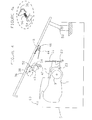
- Fig. 1 illustrates the electrophotographic toner cartridge 1 installed in base members 3 of a printer 5 (Fig. 4).
- Cartridge 1 has a top shutter 7 which is pivoted open as will be described to uncover a photoconductor drum 9 (Fig. 3).
- Base members 3 each supports a plunger rod 11, which are biased upward by a coil spring 13 surrounding each rod 11. Springs 13 abut on an upper surface 15 of each base member 3.
- Fig. 2 is a more detailed view of significant elements which pivots open shutter 7. Elements on the opposite side of the cartridge 1 are the identical, mirror-images of those shown in Fig. 2. Plunger rod 11 is pivotally connected to crank arm 20 at a location spaced from pivot pin 22, which is pivoted in base member 3.
- Arm 23 has a arc-shaped portion 24 which is pivotally attached at one end by pin 26 to shutter 7. Arm 23 is pivotally attached to cartridge 1 by pin 28 at the other end of arc-shaped portion 24. Arm 23 has straight portion 30 at approximately a right angle to portion 24. The end of portion 30 carries an abutment member 32 which extends toward cartridge 1 in a position to be engaged by the end of crank arm 20 opposite pivot pin 22. Torsion spring 34 around pin 28 connects arm 23 and cartridge 1 to tend to rotate arm 23 so as to close shutter 7.
- Fig. 4 shows printer 5 (shown largely symbolically) with lid 36 open.
- Lid 36 has mounted to it light emitting diode printhead 40, charge roller42, and, on each side of lid 36 positioned to contact each plunger rod 11, push plate 44.
- Each push plate 44 is pivoted on a bracket 46 mounted to the underside of lid 36 and biased by spring 48 with one end connected to plate 44 on the side toward hinge 50 of lid 36 and with the opposite end of spring 48 connected to lid 36.
- Charge roller42 is mounted on each side of lid 36 by a bushing 52 which is mounted in pivoting arm 54. Arm 54 rotates about pivot shaft 58.
- Torsion spring 56 (Fig. 4a) mounted on shaft 58 provides a downward force for charge roller 42 against photoconductor drum 9.
- An identical, biased mounting of charge roller 42 exists near the opposite end of charge roller 42.
- lid 36 is held by a latch 60, which may be a conventional, yieldable member.
- cartridge 1 For use in printing, cartridge 1 is initially positioned in printer 5 with no positive downward restraint except gravity. (Studs on cartridge 1 (not shown) slide into slots in printer 5 to position cartridge 1 laterally.) Lid 36 is then closed by manual pivoting with respect to hinge 50. The first mechanical interaction is each push plate 44 engaging the top of its corresponding plunger rod 11. Resistance from springs 13 is less than the resistance of springs 48, so rods 11 are pushed downward and push plates 44 do not pivot. As lowering of lid 36 continues, shutter 7 is opened as described and then charge roller 42 engages photoconductor 9. Crank arm 20 reaches its limit when abutment 32 encounters base 3. Further movement of lid 36 then pivots plates 44 against the force of springs 48. Charge roller 42 also moves on arms 54 to rotate torsion springs 56.
- springs 56 and 48 act to positively lift lid 36 a short distance, which is convenient to the operator (i.e. lid 36 "pops" open). If lid 36 is dropped or pushed downward accidentally or too hard, spring 48 is engaged to damp movement before LED 40 and charge roller 42 or other elements can make contact and therefore be damaged and before injury can occur to the operator by lid 36 slam- ming shut.
Abstract
A charging roller (42) and push plates (44) are spring mounted to the lid (36) of a printer. When the lid is closed, the plates push plungers (11) down to rotate crank arms (23), which open a shutter (7) in electrophotographic cartridge (1). This holds the cartridge in place and provides both a resilient, protective cushion for the cartridge and a pop-up action of the lid.
Description
- This invention relates to an electrophotographic imaging apparatus employing a toner cartridge which is under a closed lid during use. With such a device the cartridge must be suitably positioned and held in place during operation while the lid is closed.
- Imaging devices with operative elements in the lid are known, as established by the following: U.S. Patent Nos. 3,966,316 to Pfeifer et al; 4,538,896 to Tajima et al; 5,047,801 to Haneda et al and 5,095,334 to Nukaya. The Pfeifer et al and Tajima et al patents both have in the lid the light source for imaging and the electrical charging source for a photoconductor, and both have elements in the lid which physically interact to position removable members in the printer. This interaction, however, is by positioning rollers, while the interaction of the present invention is by a resiliently mounted pressure member. The Haneda et al and Nukaya patents have an electrical charging source and paper feed elements in the lid and removable printing elements on which the lid closes, and have nothing similar to the resiliently mounted pressure member of this invention.
- Viewed from one aspect the present invention provides an imaging apparatus comprising a removable cartridge containing toner, a photoconductive member and a shutter covering said photoconductive member when closed, a movable lid for said imaging apparatus carrying an optical member to selectively expose said photoconductive member and a charging member to electrically charge said photoconductive member, a biased push plate pivotally attached to said lid, a plunger resiliently mounted on said apparatus separate from said cartridge and positioned to contact said push plate as said lid closes, a pivotally mounted first crank arm pivotally connected to said plunger, and a second crankarm pivotally mounted on said cartridge and connected to said shutter to open and close said shutter, said first crank arm being located to rotate said second crank arm to open said shutter when said lid closes on said plunger.
- A preferred form of the present invention has a charging roller mounted in the lid on spring members, as well as the optical element in the lid. The lid also carries pivoted, spring biased push plates on opposite sides. The main body of the printer receives a toner cartridge immediately under the location of the closed lid which has plunger rods positioned under the spring biased plates and pivotally attached to crank arms. The cartridge has an upper shutter which is pivotally mounted on each side of the cartridge.
- Closing of the lid brings the push plates into contact with the rods, which pivot the crank arms to contact the shutter mounting. The shutter is moved open and the mounting continues to receive downward force through the rods. The shutter first moves to expose the photoconductor drum and the further movement of the lid brings the charge roller in contact with the photoconductor drum. The bias mounting of the charge roller provides further downward force on the cartridge.
- Should the lid be open and accidently dropped or pushed toward the closed position, the biased plates first contact the rods to cushion the movement by the bias of the rods. Continued movement is furthercush- ioned by the spring bias of the plates, thereby avoiding damage to elements in or near the lid and injury to persons near the lid. When the lid is opened, the spring mounting gives a decisive, "pop-up" response.
- An embodiment of the invention will now be described by way of example and with reference to the accompanying drawings, in which:-
- Fig. 1 is a perspective view showing the toner cartridge mounted in the imaging device prior to closing of the lid;
- Fig. 2 is a detailed view, slightly in perspective of the crank and hold mechanism for the shutter;
- Fig. 3 is an enlarged perspective view similar to Fig. 2 showing the crank and hold mechanism in the open position;
- Fig. 4 is a side view showing the lid and cartridge and crank and hold mechanism with the lid opened;
- Fig. 4a is an enlarged view of the mechanism at the region indicated in Fig. 4; and
- Fig. 5 is the same view as Fig. 4 with the lid closed.
- Fig. 1 illustrates the
electrophotographic toner cartridge 1 installed inbase members 3 of a printer 5 (Fig. 4). Cartridge 1 has atop shutter 7 which is pivoted open as will be described to uncover a photoconductor drum 9 (Fig. 3).Base members 3 each supports aplunger rod 11, which are biased upward by acoil spring 13 surrounding eachrod 11. Springs 13 abut on anupper surface 15 of eachbase member 3. - Fig. 2 is a more detailed view of significant elements which pivots
open shutter 7. Elements on the opposite side of thecartridge 1 are the identical, mirror-images of those shown in Fig. 2. Plungerrod 11 is pivotally connected tocrank arm 20 at a location spaced frompivot pin 22, which is pivoted inbase member 3. -
Arm 23 has a arc-shaped portion 24 which is pivotally attached at one end bypin 26 toshutter 7.Arm 23 is pivotally attached tocartridge 1 bypin 28 at the other end of arc-shaped portion 24.Arm 23 hasstraight portion 30 at approximately a right angle toportion 24. The end ofportion 30 carries anabutment member 32 which extends towardcartridge 1 in a position to be engaged by the end ofcrank arm 20opposite pivot pin 22. Torsionspring 34 aroundpin 28 connectsarm 23 andcartridge 1 to tend to rotatearm 23 so as to closeshutter 7. - In operation,
push plates 44 of the lid 36 (Fig. 4) of printer 5 push down on bothplunger rods 11 whenlid 36 is closed. This rotatescrank arms 20 clockwise seen in Fig. 2. The rotation causesarm 20 to engage abutment 32 and to thus rotate thearm 23. Rotation terminates when abutment 32 encounters the floor of base member 3 (Fig. 1). Fig. 3 shows these members in their final position afterlid 36 is closed. This takes place identically on both sides ofcartridge 1. Shutter 7 is moved slightly upward on the arc ofportion 24, but primarily moves laterally, where it then rests in the open position on an upper surface 35 (Fig. 2) ofcartridge 1. - Fig. 4 shows printer 5 (shown largely symbolically) with
lid 36 open.Lid 36 has mounted to it light emittingdiode printhead 40, charge roller42, and, on each side oflid 36 positioned to contact eachplunger rod 11,push plate 44. Eachpush plate 44 is pivoted on abracket 46 mounted to the underside oflid 36 and biased byspring 48 with one end connected toplate 44 on the side towardhinge 50 oflid 36 and with the opposite end ofspring 48 connected tolid 36. Charge roller42 is mounted on each side oflid 36 by a bushing 52 which is mounted in pivotingarm 54.Arm 54 rotates aboutpivot shaft 58. Torsion spring 56 (Fig. 4a) mounted onshaft 58 provides a downward force forcharge roller 42 againstphotoconductor drum 9. An identical, biased mounting of charge roller 42 (not shown) exists near the opposite end ofcharge roller 42. In the closedposition lid 36 is held by alatch 60, which may be a conventional, yieldable member. - For use in printing,
cartridge 1 is initially positioned in printer 5 with no positive downward restraint except gravity. (Studs on cartridge 1 (not shown) slide into slots in printer 5 to positioncartridge 1 laterally.)Lid 36 is then closed by manual pivoting with respect tohinge 50. The first mechanical interaction is eachpush plate 44 engaging the top of itscorresponding plunger rod 11. Resistance fromsprings 13 is less than the resistance ofsprings 48, sorods 11 are pushed downward andpush plates 44 do not pivot. As lowering oflid 36 continues,shutter 7 is opened as described and thencharge roller 42 engagesphotoconductor 9. Crankarm 20 reaches its limit when abutment 32 encountersbase 3. Further movement oflid 36 thenpivots plates 44 against the force ofsprings 48.Charge roller 42 also moves onarms 54 to rotatetorsion springs 56. - The forces of
springs cartridge 1 which are somewhat displaced laterally. Thesesecure cartridge 1 vertically. Whenlatch 60 is released, springs 48 and 56 act to positively lift lid 36 a short distance, which is convenient to the operator (i.e.lid 36 "pops" open). Iflid 36 is dropped or pushed downward accidentally or too hard,spring 48 is engaged to damp movement beforeLED 40 andcharge roller 42 or other elements can make contact and therefore be damaged and before injury can occur to the operator bylid 36 slam- ming shut.
Claims (6)
1. An imaging apparatus comprising a removable cartridge (1) containing toner, a photoconductive member (9) and a shutter (7) covering said photoconductive member when closed, a movable lid (36) for said imaging apparatus carrying an optical member (40) to selectively expose said photoconductive member and a charging member (42) to electrically charge said photoconductive member, a biased push plate (44) pivotally attached to said lid, a plunger (11) resiliently mounted on said apparatus separate from said cartridge and positioned to contact said push plate as said lid closes, a pivotally mounted first crank arm (20) pivotally connected to said plunger, and a second crank arm (23) pivotally mounted on said cartridge and connected to said shutter to open and close said shutter, said first crank arm being located to rotate said second crank arm to open said shutter when said lid closes on said plunger.
2. Apparatus as claimed in claim 1, in which said charging member (42) is a spring mounted roller.
3. Apparatus as claimed in claim 1 or 2, in which said push plate (44) is spring mounted with a spring (48) of force such as not to yield while said first crank arm (20) rotates said second crank arm (23) to open said shutter (7) and then to yield as said lid (36) is further closed.
4. A removable toner cartridge (1) for an imaging apparatus having a photoconductor member (9) and a moveable shutter (7) covering said photoconductor member in one position, said cartridge having a two crank arms (23) each pivotally connected to said cartridge on opposite sides of said shutter, each said crank arm having a first portion (24) pivotally connected to said shutter on one side of said pivot (28) to said cartridge and a second portion (30) having an abutment surface (32) extending toward said cartridge for rotating said crank on the other side of said pivot to said cartridge, said first portion being arc-shaped extending generally from said pivot to said cartridge toward said shutter and then extending generally toward said pivotal connection (26) to said shutter.
6. An imaging apparatus for receiving a removable toner cartridge (1) to form a complete imaging apparatus having a lid (36) on which is mounted a light source (40) for imaging a photoconductor member (9) in said cartridge when said lid is closed, a charge roller (42) for contacting and charging said photoconductor member when said lid is closed, said charge roller being resiliently mounted to form a firm contact with said photoconductor member when said lid is closed, a push plate (44) resiliently mounted on said lid independent of said mounting of said charge roller, and a plunger (11) mounted in said assembly and located to contact said push plate as said lid is closed.
7. Apparatus as claimed in claim 6, in which said push plate (44) is pivotally mounted with a spring (48) of force such as not to yield while said plunger (11) moves a first distance and to then yield as said lid (36) is further closed.
Applications Claiming Priority (2)
| Application Number | Priority Date | Filing Date | Title |
|---|---|---|---|
| US99814 | 1993-07-29 | ||
| US08/099,814 US5365315A (en) | 1993-07-29 | 1993-07-29 | Imaging device with cartridge and lid interaction |
Publications (2)
| Publication Number | Publication Date |
|---|---|
| EP0636953A2 true EP0636953A2 (en) | 1995-02-01 |
| EP0636953A3 EP0636953A3 (en) | 1996-05-08 |
Family
ID=22276751
Family Applications (1)
| Application Number | Title | Priority Date | Filing Date |
|---|---|---|---|
| EP94305422A Withdrawn EP0636953A3 (en) | 1993-07-29 | 1994-07-22 | Imaging apparatus with cartridge and lid interaction. |
Country Status (3)
| Country | Link |
|---|---|
| US (1) | US5365315A (en) |
| EP (1) | EP0636953A3 (en) |
| JP (1) | JPH0764463A (en) |
Families Citing this family (23)
| Publication number | Priority date | Publication date | Assignee | Title |
|---|---|---|---|---|
| JPH07114144A (en) * | 1993-10-15 | 1995-05-02 | Fuji Photo Film Co Ltd | Paper magazine |
| US5526097A (en) * | 1995-06-07 | 1996-06-11 | Lexmark International, Inc. | Cartridge utilizing a plurality of contact charging members |
| US5758231A (en) * | 1996-12-20 | 1998-05-26 | Lexmark International, Inc. | Venting plug in toner cartridge |
| US5794102A (en) * | 1996-12-20 | 1998-08-11 | Lexmark International, Inc. | Toner cartridge with heat shield shutter |
| US5802432A (en) * | 1996-12-20 | 1998-09-01 | Lexmark International, Inc. | Toner cartridge with housing and pin construction |
| US5875378A (en) * | 1996-12-20 | 1999-02-23 | Lexmark International, Inc. | Toner cartridge with hopper exit agitator |
| US5758233A (en) * | 1996-12-20 | 1998-05-26 | Lexmark International, Inc. | Toner cartridge with locating on photoconductor shaft |
| US5768661A (en) * | 1996-12-20 | 1998-06-16 | Lexmark International, Inc. | Toner cartridge with external planar installation guides |
| JP3300245B2 (en) * | 1997-02-19 | 2002-07-08 | シャープ株式会社 | Image forming device |
| US5752135A (en) * | 1997-05-09 | 1998-05-12 | Lexmark International, Inc. | Door operated charge member positioning |
| US6079084A (en) * | 1997-10-17 | 2000-06-27 | Nu-Kote International, Inc. | Method and apparatus for removing and replacing a wiper blade assembly and a corona grid in a toner cartridge |
| JP3799227B2 (en) * | 1999-11-30 | 2006-07-19 | キヤノン株式会社 | Image forming apparatus |
| US6801733B2 (en) * | 2003-01-21 | 2004-10-05 | Static Control Components, Inc. | Printer cartridge and method of making or refurbishing |
| US7447464B2 (en) * | 2003-12-19 | 2008-11-04 | Cartridge Corporation Of America, Inc. | Toner cartridge having a collapsible actuating structure |
| US7120375B2 (en) * | 2004-01-29 | 2006-10-10 | Lexmark International, Inc. | Cover prop mechanism |
| JP4378299B2 (en) * | 2004-02-20 | 2009-12-02 | キヤノン株式会社 | Process cartridge and electrophotographic image forming apparatus |
| KR100644658B1 (en) | 2004-12-07 | 2006-11-10 | 삼성전자주식회사 | Image forming apparatus |
| EP1842107A1 (en) * | 2005-01-25 | 2007-10-10 | GCC IP Pty Limited | Activation mechanism for a shutter |
| KR100739739B1 (en) * | 2005-10-13 | 2007-07-13 | 삼성전자주식회사 | A finisher and Multi function peripheral having the same |
| US7321739B1 (en) * | 2007-04-30 | 2008-01-22 | Lexmark International, Inc. | Cartridge with a handle for use with an image forming device |
| US10576765B2 (en) * | 2016-04-29 | 2020-03-03 | Hewlett-Packard Development Company, L.P. | Printer door hinge assembly |
| CN106597825B (en) * | 2016-09-21 | 2018-05-22 | 纳思达股份有限公司 | A kind of handle box |
| US10444665B2 (en) * | 2017-10-03 | 2019-10-15 | Canon Kabushiki Kaisha | Image forming apparatus |
Citations (5)
| Publication number | Priority date | Publication date | Assignee | Title |
|---|---|---|---|---|
| US4873548A (en) * | 1985-06-06 | 1989-10-10 | Canon Kabushiki Kaisha | Image forming apparatus comprising a main assembly having a top frame adapted to swing open and closed with respect to a bottom frame and having process cartridge detachably mounted in the main assembly |
| JPH03123380A (en) * | 1989-10-07 | 1991-05-27 | Canon Inc | Image forming device |
| US5083158A (en) * | 1989-10-25 | 1992-01-21 | Brother Kogyo Kabushiki Kaisha | Photoconductive cartridge having shutter locking device for holding opening of the cartridge in closed position |
| US5095335A (en) * | 1989-09-19 | 1992-03-10 | Canon Kabushiki Kaisha | Copier with retractable charging unit to prevent damage to drum when removing process cartridge |
| US5231453A (en) * | 1991-04-23 | 1993-07-27 | Brother Kogyo Kabushiki Kaisha | Image recording apparatus with rolled protective cover for process unit |
Family Cites Families (5)
| Publication number | Priority date | Publication date | Assignee | Title |
|---|---|---|---|---|
| DE2436301A1 (en) * | 1974-07-27 | 1976-02-12 | Agfa Gevaert Ag | ELECTROSTATIC COPY DEVICE |
| JPS57154255A (en) * | 1981-03-18 | 1982-09-24 | Canon Inc | Image forming apparatus |
| US5047801A (en) * | 1988-12-06 | 1991-09-10 | Konica Corporation | Color image forming apparatus having the developing means and cleaning means formed as a detachable unit |
| JPH03229272A (en) * | 1990-02-02 | 1991-10-11 | Ricoh Co Ltd | Electrophotographic recording device |
| KR950001428Y1 (en) * | 1990-09-29 | 1995-03-06 | 삼성전자 주식회사 | Opening/closing device of a photosensitive drum cover |
-
1993
- 1993-07-29 US US08/099,814 patent/US5365315A/en not_active Expired - Fee Related
-
1994
- 1994-07-19 JP JP6188810A patent/JPH0764463A/en not_active Withdrawn
- 1994-07-22 EP EP94305422A patent/EP0636953A3/en not_active Withdrawn
Patent Citations (5)
| Publication number | Priority date | Publication date | Assignee | Title |
|---|---|---|---|---|
| US4873548A (en) * | 1985-06-06 | 1989-10-10 | Canon Kabushiki Kaisha | Image forming apparatus comprising a main assembly having a top frame adapted to swing open and closed with respect to a bottom frame and having process cartridge detachably mounted in the main assembly |
| US5095335A (en) * | 1989-09-19 | 1992-03-10 | Canon Kabushiki Kaisha | Copier with retractable charging unit to prevent damage to drum when removing process cartridge |
| JPH03123380A (en) * | 1989-10-07 | 1991-05-27 | Canon Inc | Image forming device |
| US5083158A (en) * | 1989-10-25 | 1992-01-21 | Brother Kogyo Kabushiki Kaisha | Photoconductive cartridge having shutter locking device for holding opening of the cartridge in closed position |
| US5231453A (en) * | 1991-04-23 | 1993-07-27 | Brother Kogyo Kabushiki Kaisha | Image recording apparatus with rolled protective cover for process unit |
Non-Patent Citations (1)
| Title |
|---|
| PATENT ABSTRACTS OF JAPAN vol. 015 no. 335 (P-1242) ,26 August 1991 & JP-A-03 123380 (CANON INC) 27 May 1991, * |
Also Published As
| Publication number | Publication date |
|---|---|
| US5365315A (en) | 1994-11-15 |
| JPH0764463A (en) | 1995-03-10 |
| EP0636953A3 (en) | 1996-05-08 |
Similar Documents
| Publication | Publication Date | Title |
|---|---|---|
| EP0636953A2 (en) | Imaging apparatus with cartridge and lid interaction | |
| US5262827A (en) | Light emitting diode printer | |
| US5095335A (en) | Copier with retractable charging unit to prevent damage to drum when removing process cartridge | |
| EP1298502B1 (en) | Electrophotographic image forming apparatus having a detachable process cartridge | |
| EP1650776A1 (en) | Open/close switch mechanism having simple configuration | |
| US5614992A (en) | Image forming apparatus with improved jam clearance operation | |
| EP0530491B1 (en) | Electrophotographic image forming apparatus with detachable imaging cartridge | |
| CA1079762A (en) | Multibin shingling type stack feeder | |
| JPS60260063A (en) | Electrophotostatic type copying equipment and loading/ unloading processing cartrige | |
| JP4593700B2 (en) | Image forming apparatus | |
| EP0545067A2 (en) | Image-forming machine | |
| KR880006578A (en) | Developing device | |
| US5005053A (en) | Image-forming machine having a process assembly comprising two independently movable units | |
| KR20020016389A (en) | Laser printer | |
| US4866483A (en) | Cleaning station for use in an electrophotographic print engine | |
| JPS60260064A (en) | Electrophotostatic type copying equipment and loading/ unloading processing cartrige | |
| JPS6333153B2 (en) | ||
| US4908674A (en) | Image forming apparatus | |
| US5752135A (en) | Door operated charge member positioning | |
| EP0507528B1 (en) | Process cartridge and image forming system with it | |
| JPH086471A (en) | Image-forming device | |
| JPH0459634B2 (en) | ||
| JPS61254956A (en) | Supporting device for developing device | |
| JPH07120134B2 (en) | Copier | |
| JP3484326B2 (en) | Process cartridge and image forming apparatus |
Legal Events
| Date | Code | Title | Description |
|---|---|---|---|
| PUAI | Public reference made under article 153(3) epc to a published international application that has entered the european phase |
Free format text: ORIGINAL CODE: 0009012 |
|
| AK | Designated contracting states |
Kind code of ref document: A2 Designated state(s): DE FR GB |
|
| PUAL | Search report despatched |
Free format text: ORIGINAL CODE: 0009013 |
|
| AK | Designated contracting states |
Kind code of ref document: A3 Designated state(s): DE FR GB |
|
| STAA | Information on the status of an ep patent application or granted ep patent |
Free format text: STATUS: THE APPLICATION IS DEEMED TO BE WITHDRAWN |
|
| 18D | Application deemed to be withdrawn |
Effective date: 19970201 |