EP0635710A2 - Method and apparatus for surface area liquid transfer - Google Patents
Method and apparatus for surface area liquid transfer Download PDFInfo
- Publication number
- EP0635710A2 EP0635710A2 EP94202115A EP94202115A EP0635710A2 EP 0635710 A2 EP0635710 A2 EP 0635710A2 EP 94202115 A EP94202115 A EP 94202115A EP 94202115 A EP94202115 A EP 94202115A EP 0635710 A2 EP0635710 A2 EP 0635710A2
- Authority
- EP
- European Patent Office
- Prior art keywords
- liquid
- test
- test element
- dispensing
- supporting surface
- Prior art date
- Legal status (The legal status is an assumption and is not a legal conclusion. Google has not performed a legal analysis and makes no representation as to the accuracy of the status listed.)
- Ceased
Links
Images


Classifications
-
- B—PERFORMING OPERATIONS; TRANSPORTING
- B01—PHYSICAL OR CHEMICAL PROCESSES OR APPARATUS IN GENERAL
- B01L—CHEMICAL OR PHYSICAL LABORATORY APPARATUS FOR GENERAL USE
- B01L3/00—Containers or dishes for laboratory use, e.g. laboratory glassware; Droppers
- B01L3/02—Burettes; Pipettes
- B01L3/0241—Drop counters; Drop formers
- B01L3/0244—Drop counters; Drop formers using pins
- B01L3/0255—Drop counters; Drop formers using pins characterized by the form or material of the pin tip
-
- B—PERFORMING OPERATIONS; TRANSPORTING
- B01—PHYSICAL OR CHEMICAL PROCESSES OR APPARATUS IN GENERAL
- B01L—CHEMICAL OR PHYSICAL LABORATORY APPARATUS FOR GENERAL USE
- B01L3/00—Containers or dishes for laboratory use, e.g. laboratory glassware; Droppers
- B01L3/02—Burettes; Pipettes
-
- G—PHYSICS
- G01—MEASURING; TESTING
- G01N—INVESTIGATING OR ANALYSING MATERIALS BY DETERMINING THEIR CHEMICAL OR PHYSICAL PROPERTIES
- G01N35/00—Automatic analysis not limited to methods or materials provided for in any single one of groups G01N1/00 - G01N33/00; Handling materials therefor
- G01N35/00029—Automatic analysis not limited to methods or materials provided for in any single one of groups G01N1/00 - G01N33/00; Handling materials therefor provided with flat sample substrates, e.g. slides
-
- B—PERFORMING OPERATIONS; TRANSPORTING
- B01—PHYSICAL OR CHEMICAL PROCESSES OR APPARATUS IN GENERAL
- B01L—CHEMICAL OR PHYSICAL LABORATORY APPARATUS FOR GENERAL USE
- B01L2300/00—Additional constructional details
- B01L2300/06—Auxiliary integrated devices, integrated components
- B01L2300/069—Absorbents; Gels to retain a fluid
-
- B—PERFORMING OPERATIONS; TRANSPORTING
- B01—PHYSICAL OR CHEMICAL PROCESSES OR APPARATUS IN GENERAL
- B01L—CHEMICAL OR PHYSICAL LABORATORY APPARATUS FOR GENERAL USE
- B01L2400/00—Moving or stopping fluids
- B01L2400/02—Drop detachment mechanisms of single droplets from nozzles or pins
- B01L2400/022—Drop detachment mechanisms of single droplets from nozzles or pins droplet contacts the surface of the receptacle
- B01L2400/025—Drop detachment mechanisms of single droplets from nozzles or pins droplet contacts the surface of the receptacle tapping tip on substrate
-
- B—PERFORMING OPERATIONS; TRANSPORTING
- B01—PHYSICAL OR CHEMICAL PROCESSES OR APPARATUS IN GENERAL
- B01L—CHEMICAL OR PHYSICAL LABORATORY APPARATUS FOR GENERAL USE
- B01L3/00—Containers or dishes for laboratory use, e.g. laboratory glassware; Droppers
- B01L3/02—Burettes; Pipettes
- B01L3/0241—Drop counters; Drop formers
- B01L3/0244—Drop counters; Drop formers using pins
-
- G—PHYSICS
- G01—MEASURING; TESTING
- G01N—INVESTIGATING OR ANALYSING MATERIALS BY DETERMINING THEIR CHEMICAL OR PHYSICAL PROPERTIES
- G01N35/00—Automatic analysis not limited to methods or materials provided for in any single one of groups G01N1/00 - G01N33/00; Handling materials therefor
- G01N35/10—Devices for transferring samples or any liquids to, in, or from, the analysis apparatus, e.g. suction devices, injection devices
- G01N2035/1027—General features of the devices
- G01N2035/1034—Transferring microquantities of liquid
- G01N2035/1037—Using surface tension, e.g. pins or wires
-
- G—PHYSICS
- G01—MEASURING; TESTING
- G01N—INVESTIGATING OR ANALYSING MATERIALS BY DETERMINING THEIR CHEMICAL OR PHYSICAL PROPERTIES
- G01N35/00—Automatic analysis not limited to methods or materials provided for in any single one of groups G01N1/00 - G01N33/00; Handling materials therefor
- G01N35/10—Devices for transferring samples or any liquids to, in, or from, the analysis apparatus, e.g. suction devices, injection devices
- G01N35/1095—Devices for transferring samples or any liquids to, in, or from, the analysis apparatus, e.g. suction devices, injection devices for supplying the samples to flow-through analysers
-
- Y—GENERAL TAGGING OF NEW TECHNOLOGICAL DEVELOPMENTS; GENERAL TAGGING OF CROSS-SECTIONAL TECHNOLOGIES SPANNING OVER SEVERAL SECTIONS OF THE IPC; TECHNICAL SUBJECTS COVERED BY FORMER USPC CROSS-REFERENCE ART COLLECTIONS [XRACs] AND DIGESTS
- Y10—TECHNICAL SUBJECTS COVERED BY FORMER USPC
- Y10T—TECHNICAL SUBJECTS COVERED BY FORMER US CLASSIFICATION
- Y10T436/00—Chemistry: analytical and immunological testing
- Y10T436/11—Automated chemical analysis
Definitions
- the present invention relates to a method and apparatus for surface area liquid transfer, for use in clinical analyzers for testing of liquid analytes, and is particularly concerned with a method and apparatus for transferring patient sample to a test element in such analyzers.
- a patient sample is introduced and caused to interact with a reaction chemistry to produce a signal involving the analyte of choice, for detection by a sensing apparatus.
- a preferred technique used by analyzers involves the so-called dried assay technology so that patient sample is applied to dried test slide elements, each having a dried reactant layer.
- Analyzers and test elements using this technology include those manufactured by Eastman Kodak Company, both under the trademark "EKTACHEMTM".
- a patient sample is conveyed to a processing station within an analyzer where it is dispensed on to a test element.
- the sample is dispensed by means of a point source, usually a disposable pipette tip, which is positioned a short distance above the test element surface and has a tip orifice from where the sample is expelled (or metered) on to the test element.
- a point source usually a disposable pipette tip
- sample delivered from a point source has to spread horizontally, as well as vertically, through the predetermined test volume of the test element.
- the need for both directions of spreading introduces the possibility of flow irregularities.
- a patient may have a serum, plasma or whole blood sample which may contain a high fat content, (that is, containing a higher percentage of lipids and lipo-proteins than a "normal" patient).
- a high fat content that is, containing a higher percentage of lipids and lipo-proteins than a "normal” patient.
- the presence of varying amounts of biological components and salts in the patient sample can produce a variation in the sample's viscosity, surface tension and contact angle, impacting its ability to outwardly spread in a uniform manner when dispensed as a drop from a suspended pipette tip on to a test element.
- Non-uniformity in the spreadability of a patient liquid may affect the accuracy of the detection of the analyte of choice, especially if the analyzer detection means is focused on only a portion of the chemistry portion of the test element on to which a patient sample has been dispensed. This type of non-uniformity is possible with any body fluid, such as blood serum, urine, and so forth, and may extend as well to control or calibration liquids that are commonly utilized in known clinical analyzers.
- the above problems are generally known as "matrix effects" and are based on differences in patient liquid samples, as well as sample interaction with the spreading layer of the chemistry portion of a test element.
- the spreading layer assists in the migration of the liquid sample across the chemistry portion of the element and in general it works well to counter these effects.
- An example of a spreading layer is described in greater detail in US-A-3 992 158.
- a spreading layer be added to the chemistry portion of a test element to promote sample migration is expensive and complex.
- point source dispensing systems have other drawbacks. For example, it is usually required that an additional volume of patient liquid be dispensed on to the test element to provide a sufficiently uniform detection or read area. Typically as much as 10 ⁇ l of a patient liquid can be required to produce an effective read area having a diameter of 3mm. This, in turn, also requires that the chemistry portion of the test element be provided with a larger surface area to accept the additional volume of patient liquid dispensed on to the test element. Further, the dispensing of additional quantities of patient liquid from a point source above the test element also increases the probability of outwardly diffusing or washout of the reaction chemistry, effectively diluting the chemical portion of the test element.
- the present invention solves the above stated needs by providing a method and related means of metering a sample on to a test element without concern for the effects of fluid adhesion or flow characteristics of a particular biological liquid which occur when dispensing from conventional point source metering systems on to a relatively large test slide surface area.
- a method of dispensing a liquid sample on to a test element having a test volume subtending a surface area for that volume for receiving the liquid sample comprising the steps of:-
- a liquid dispensing device for dispensing a liquid sample on to a test element having a test surface
- the device comprising:- a main body portion; a transfer portion supported by the main body portion for engagement with a test element, the transfer portion having a liquid-impermeable supporting surface for supporting a liquid over an area approximately equal to the area of the test surface of the test element; and absorbing means disposed about the periphery of the transfer portion for absorbing excess liquid from the liquid-impermeable supporting surface prior to dispensing therefrom.
- a method and associated apparatus are provided in which a liquid sample can be applied on to a test slide element which pre-spreads the liquid uniformly over a contact surface area which matches the test element test surface area, thus negating the matrix effects which impact the diffusivity of conventionally dispensed systems.
- Another advantageous feature of the invention is that a smaller quantity of liquid can be directly and evenly applied to the test volume of a test element with reduced consideration of the fluid characteristics of a dispensed liquid from a suspended tip.
- a further advantageous feature of the invention is that the ability to uniformly dispense a patient liquid on to a test element eliminates the necessity for a test element having a pre-incorporated horizontally diffusing spreading layer thereby allowing test elements to be manufactured more easily and inexpensively.
- a still further advantageous feature of the present invention is that by uniformly distributing a patient sample to the test volume of a test element there is provide less need for an oversized chemistry portion to provide an adequately sized detection area, thereby producing an additional and significant savings in the manufacture of test elements.
- a still further advantageous feature of the present invention is that a surface-dispersed quantity, as defined below, can be delivered to the test volume of a test element all at once, providing a relatively constant concentration level of liquid across the detection read area without significant washout of the dried chemistry or transient liquid flow after delivery.
- the invention is hereinafter described in the context of the preferred embodiments.
- the invention is useful regardless of the liquid being dispensed, the kind of analyzer which is being used, and regardless of whether the surface is a dried slide test element, or even any kind of test element, since the described methods and associated apparatus can also be used to meter on to any surface.
- surface-dispersed quantity means, a quantity in which the surface area/volume ratio is approximately 1:1, for example, if a 10cm3 volume has a 10cm2 dispersed surface area and a 1cm thickness, its ratio is 1:1. Ratios of 9:10 or 11:10 are included here.
- FIG. 1 A preferred embodiment of the present invention is shown in Figures 1, 2A, and 2B.
- a transfer element 10 having a main body 2 comprising an upper surface 4 and a preferably circular lower surface 6.
- the shape of lower surface 6 may be varied, but preferably should be congruent with the shape of the test surface area to be contacted, whatever that may be.
- lower surface 6 is defined, in part, by a liquid-supporting portion 7 defined by a series of substantially parallel, V-shaped grooves 8, disposed over the majority of the area of surface 6.
- the shapes and depths of grooves 8, however, may be varied to be rectangular, convex, concave, U-shaped, and so forth. Alternate configurations can also be provided for defining liquid supporting portion 7; for example, a diamond-like pattern such as illustrated in Figure 2B.
- grooves 8 have a depth of 200 ⁇ m and a spacing of 400 ⁇ m.
- liquid-supporting portion 7 can alternatively be textured (not shown), as opposed to providing grooves, provided capability is provided for supporting a sufficient quantity of liquid to effectively coat the reagent member, or other reactive portion of a test element.
- Lower surface 6 is further defined by a ring portion 11, preferably circumferentially and substantially disposed about the entire outer periphery 5 of liquid-supporting portion 7, and having an outer peripheral edge 16.
- ring and liquid-supporting portions 7, 11 are made from the same material, except that ring portion 11 is smooth.
- main body 2, Figure 1 can be constructed of almost any material, it is preferred that lower surface 6 be made from a compliant and liquid-impermeable material.
- main body 2, including lower surface 6, is made from a plastic with minimal protein adhesion, such as polypropylene or polyethylene.
- Ring portion 11 and liquid-supporting portion 7 further define a diameter D1 which is preferably at least equal to the detection or read area of the chemistry portion of a test element.
- grooves 8 are formed in surface 6 between ring portion 11, to form a series of ribs 14.
- ribs 14 are rounded, though this may not be required if lower surface 6 is made from a fairly compliant material, so as not to damage the chemistry portion of a test element when brought into contact therewith.
- Contacting surface 9 of ring portion 11 is made to be flush with ribs 14, ring portion 11 being substantially continuous with the exception of a variable number of small vent channels 12.
- a disc 17, Figure 1 made of a liquid absorbent material is preferably continuously disposed about main body 2, adjacent outer peripheral edge 16 and generally in contact with ring portion 11, except in the vicinity of vent channels 12, Figure 2, where it is slightly undercut so as not to prematurely siphon liquid from grooves 8.
- cross-channels (not shown) arranged substantially perpendicular to grooves 8 can also be provided across surface 6 for this purpose.
- disc 17 is made of a high density open-cell urethane foam, though other nonreactive, liquid absorbing materials such as an absorbent paper may be provided.
- Disc 17 is made to extend inwardly radially from edge 16, attaching to upper surface 4.
- Transfer element 10 is preferably made to be both pivotably and vertically movable.
- a ball 20 is seated within a centrally disposed recess 18 defined in upper surface 4.
- recess 18 is an opening sized to receive ball 20 and is defined by a substantially orthogonal configuration, having a bottom surface 15 and side seating surfaces 21.
- Ball 20, in the embodiment illustrated, is made of DelrinTM, a polyformaldehyde acetal resin sold by E.I. DuPont de Nemours & Company, though other moldable plastics such as polyethylene or polycarbonate are also acceptable. It is preferable, however, that ball 20 be provided with a relatively smooth outer surface for allowing ball 20 to be engageably movable within recess 18 and along side seating surfaces 21.
- One end 23 of a mounting arm 22 is threaded or otherwise fastened into a bore 25 defined in ball 20, bore 25 being oppositely situated from the portion of ball 20 which is engaged into recess 18.
- the remaining end 27 of mounting arm 22 extends upwardly, in the embodiment illustrated, and is engaged into lower end 29 of a cylindrical supporting member 26.
- the other or upper end 31 of supporting member 26 is inserted into a force-application member 32, having a centrally disposed sleeve 30.
- supporting member 26 is shaped so as to be slidingly engageable within sleeve 30.
- a helical spring 24, having a length L1 is positioned between upper surface 4 and a lower surface 33 of force application member 32, and is circumferentially disposed about supporting member 26.
- Force application member 32 is mechanically attached to an analyzer (not shown).
- ball 20, mounting arm 22, spring 24, supporting member 26, and force application member 32 can be made part of transfer element 10, or be part of the analyzer, the remainder of which is not shown. It can be seen that other available means of making the transfer element pivotable can be used, such as by providing supporting member 26 from a flexible material so as to allow it to bend from a neutral position.
- Figures 3A, 3B, 4A, 4B, 5A, 5B and 6 illustrate a method of dispensing a quantity of liquid sample, such as blood serum, on to a test element which permits the quantitative analysis of analytes in the liquid sample using the apparatus discussed above and illustrated in Figures 1 and 2.
- a quantity of liquid sample such as blood serum
- transfer element 10 is placed into a container 34 containing a patient liquid 36.
- container 34 containing a patient liquid 36.
- the location and requirements of container 34 can be varied such that it may be positioned at a station within the confines of a clinical analyzer, or alternatively in an off-line position.
- Container 34 in terms of location or configuration, is not considered an essential element of the present invention.
- Transfer element 10 is first lowered into container 34, as illustrated in Figure 3B, immersing lower surface 6 to a level in which grooves 8 of liquid-supporting portion 7, if present, can acquire contained patient liquid 36 thereupon. Most of the air contained within grooves 8 is vented outwardly of transfer element 10 through venting channels 12, Figure 2A. Transfer element 10 is then withdrawn from container 34. As shown in Figure 4A, as transfer element 10 is removed from container 34 a quantity of liquid 44 is retained on supporting portion 7, such as within grooves 8 due to the adhesion of fluid to ribs 14.
- meniscus 41 As transfer element 10 is withdrawn from container 34 a meniscus 41, containing an excess of patient liquid in addition to quantity 44, Figure 4B required to fill grooves 8, forms on lower surface 6 due to the surface tension of the patient liquid. It is preferable that meniscus 41 be removed prior to the dispensing of liquid from transfer element 10 in order to avoid potential flooding of the test slide element when liquid is transferred, and further to more adequately control the volume of liquid to be applied thereto.
- Container 34 preferably, provides means for scraping against lower surface 6 to wipe excess liquid from surface 6 and grooves 8.
- an edge 38 is provided with a knife edge 35 as shown in Figure 4A and 4B.
- transfer element 10 can be drawn,in the direction of arrow 42, along knife edge 35, to remove meniscus 41, Figure 4B, leaving a uniform layer of patient liquid 44 within grooves 8.
- the excess fluid comprising meniscus 41 is squeegeed from one side of lower surface 6 to the other while a quantity of fluid 44 within grooves 8 remains.
- the external energy supplied to grooves 8 by scraping knife edge 35 against surface 6 serves to evacuate air pockets formed within grooves 8, allowing the grooves to fill with liquid.
- Knife edge 35 can be made from known materials.
- scraping apparatus 38 can be made part of the analyzer, such as if container 34 is located off-line.
- a known volume of liquid material 44 as defined by the size and number of grooves 8, is uniformly supported by surface 6 prior to transferring liquid material to a test element.
- a quantity of 2 ⁇ l is retained within grooves 8, over a diameter D1 of 4mm.
- transfer element 10 is positioned over a test element 50 having a plastic support frame 52, and a centrally disposed chemistry portion 58 having a circular configuration, a test volume V subtending test surface area S, and having a diameter D3.
- the chemistry portion 58 further comprises dried reagents distributed through two layers 60, 61 on a support 54. In the embodiment illustrated, D3 is also 4mm.
- transfer element 10 is lowered until ribs 14 are brought into contact with chemistry portion 58, and specifically, reagent layer 60.
- liquid-supporting portion 7 of lower surface 6 has a diameter D1 which is preferably at least equal to diameter D2, Figure 5B, Figure 7, of detection target area 59 of chemistry portion 58.
- chemistry portion 58 has a diameter D1 of 4mm and detection target area diameter D2 is equal to 3mm. Such equality of diameters removes the need to have horizontal spreading of the liquid across test volume V.
- Figure 6 illustrates an optional pivotability feature of transfer element 10 in the event that slide element 50 is not aligned with respect to lower surface 6.
- the position of slide element 50 defines a plane 70, plane 70 being skewed from vertical centerline 74 such that plane 70 is not orthogonal thereto.
- transfer element 10 is made to pivot about centerline 74 due to downward force F, thereby allowing surface 6 to align substantially parallel to plane 70 as ball 20 impinges upon side surfaces 21 of recess 18 allowing transfer element 10 to rotate counterclockwise, as illustrated by arrow 71, until surface 6 contacts end 75.
- the compressive load levels applied also insures chemistry portion 58 will not be damaged.
- a compressive force of 0.14N (0.5ozf) is sufficient to transfer a patient liquid to chemistry portion 58 without damage thereto.
- the amount of force required can be varied depending upon material properties and the fragility of the chemistry portion provided.
- rounding the ribs 14 of liquid-supporting portion 7 is also preferable to avoid damage to chemistry portion 58.
- Transfer element 10 is then withdrawn from slide test element 50 as illustrated in Figure 5B, by arrow 69.
- the method herein described eliminates the need for a spreading layer to horizontally diffuse the patient fluid throughout reagent layers 60, 61 in that the liquid sample has been effectively and uniformly distributed over the entire surface area, all at once, as a surface-dispersed quantity to the test volume V of element 50 to permit detection of the analyte of interest.
- the manufacture of test slide elements, and in particular the manufacture of the chemistry portion contained therein is simplified.
- Figure 8A depicts a generalized plot of sample concentration (denoted as C) versus horizontal radial distance from centerline 74, Figure 5A for a point source dispensing system as typically described above.
- concentration level C begins to become variable markedly at approximately 2mm, which is approximately the dimension of the pipette tip exterior diameter as the tip vertically delivers the sample as a single droplet to the test element.
- a variable level of C is thereafter found as R increases outwardly due to the outward spread of the variably viscous sample liquid from the centrally disposed droplet.
- t1 there is a tendency for the concentration gradient to equilibrate, or redistribute, to some degree due to diffusion, as represented by the dashed profile.
- t1 is 1 to 5 minutes, though the time taken to equilibrate, or redistribute can be varied depending upon the diffusivity of compounds used.
- Such a transient change in the concentration level can directly affect the detection results as read by an analyzer, particularly in rate-type chemistries.
- the time required for complete equilibration is lengthy and generally unpredictable due to the makeup of individual samples.
- the chemistry portion 58' of a typical test element 50, having a sample dispensed from a point source (not shown), has a diameter D4 of at least 11mm to provide a detection or read area 59 having a diameter D2 of 3mm.
- the present invention by delivering a quantity of patient liquid all at once to an area at least equal to detection area 59 requires a smaller chemistry portion 58.
- chemistry portion 58 has a diameter D3 of 4mm, or roughly the same size D1 of lower surface 6.
- approximately 2 ⁇ l is required to fill the smaller chemistry portion 58, as opposed to 10 ⁇ l or more being required for point source dispensing systems having larger chemistry portions.
- a quantity of a liquid diluent can be directly applied all at once to the chemistry portion of a test element using the method and apparatus described herein, prior to the application of a patient sample.
Abstract
Description
- The present invention relates to a method and apparatus for surface area liquid transfer, for use in clinical analyzers for testing of liquid analytes, and is particularly concerned with a method and apparatus for transferring patient sample to a test element in such analyzers.
- In the field of clinical analyzers for the testing of liquid analytes, a patient sample is introduced and caused to interact with a reaction chemistry to produce a signal involving the analyte of choice, for detection by a sensing apparatus. A preferred technique used by analyzers involves the so-called dried assay technology so that patient sample is applied to dried test slide elements, each having a dried reactant layer. Analyzers and test elements using this technology include those manufactured by Eastman Kodak Company, both under the trademark "EKTACHEM™".
- In a conventional operation, a patient sample is conveyed to a processing station within an analyzer where it is dispensed on to a test element. The sample is dispensed by means of a point source, usually a disposable pipette tip, which is positioned a short distance above the test element surface and has a tip orifice from where the sample is expelled (or metered) on to the test element. A metering tip method of dispensing patient liquid is described in US-A-5 143 849.
- However, there are a number of problems relating to a metering technique such as those typically described.
- First, it is important to understand that sample delivered from a point source has to spread horizontally, as well as vertically, through the predetermined test volume of the test element. The need for both directions of spreading introduces the possibility of flow irregularities.
- Second, the reliability of test results is impacted by the sensitivity occurring due to differences in the makeup of samples between patients. For example, a patient may have a serum, plasma or whole blood sample which may contain a high fat content, (that is, containing a higher percentage of lipids and lipo-proteins than a "normal" patient). These sorts of differences are not, however, limited to non-average patients; differences in samples between patients in the so-called "normal" range may also impact the accuracy of test results.
- In some cases, the presence of varying amounts of biological components and salts in the patient sample can produce a variation in the sample's viscosity, surface tension and contact angle, impacting its ability to outwardly spread in a uniform manner when dispensed as a drop from a suspended pipette tip on to a test element. Non-uniformity in the spreadability of a patient liquid may affect the accuracy of the detection of the analyte of choice, especially if the analyzer detection means is focused on only a portion of the chemistry portion of the test element on to which a patient sample has been dispensed. This type of non-uniformity is possible with any body fluid, such as blood serum, urine, and so forth, and may extend as well to control or calibration liquids that are commonly utilized in known clinical analyzers.
- The above problems are generally known as "matrix effects" and are based on differences in patient liquid samples, as well as sample interaction with the spreading layer of the chemistry portion of a test element. The spreading layer assists in the migration of the liquid sample across the chemistry portion of the element and in general it works well to counter these effects. An example of a spreading layer is described in greater detail in US-A-3 992 158.
- However, the requirement that a spreading layer be added to the chemistry portion of a test element to promote sample migration is expensive and complex. In addition, and notwithstanding the use of a spreading layer, point source dispensing systems have other drawbacks. For example, it is usually required that an additional volume of patient liquid be dispensed on to the test element to provide a sufficiently uniform detection or read area. Typically as much as 10µl of a patient liquid can be required to produce an effective read area having a diameter of 3mm. This, in turn, also requires that the chemistry portion of the test element be provided with a larger surface area to accept the additional volume of patient liquid dispensed on to the test element. Further, the dispensing of additional quantities of patient liquid from a point source above the test element also increases the probability of outwardly diffusing or washout of the reaction chemistry, effectively diluting the chemical portion of the test element.
- There are other effects which may produce test variability which result from dispensing a volume of liquid sample from a point source. The ability of a point source, such as a pipette tip, to adequately target on to a test element so that it can be analyzed is directly influenced by flow characteristics of the liquid to be tested. These characteristics are affected by factors such as the viscosity, surface tension, contact angle and temperature of the liquid, the volume dispensed, shape of the tip nozzle, the distance the tip is suspended above the test element, the centering of the tip above the test slide, and the makeup of the sample to be tested.
- Other factors such as the amount of ambient air flow in the vicinity of the dispensed liquid, must also be considered, and all factors may impact upon the accuracy of results. In addition, it is also known that liquid dispensed by a suspended point source has a tendency to move up the exterior surface of the dispensing container, rather than down on to the test element designed to receive the liquid. This problem, known as perfusion, has been an occasional but persistent problem with clinical analyzers using the dispensing means described, altering the volume of liquid which is subsequently dispensed. In addition, the horizontal or outward flow of a point source dispensed liquid varies over time, affecting in particular rate-type chemistries which are also time dependent.
- It has been a problem, therefore, to provide a metering method which will allow patient liquid to be deposited on to a test element without the variability in testing results which are possible using known point source techniques.
- It has also been a problem to provide a method of dispensing a smaller quantity of a patient liquid on toa test element in a substantially uniform manner which will minimize the flow characteristics of the dispensed liquid, as well as washout, and produce an effective detection area for an analyzer.
- There is a further problem of providing a method of dispensing a patient sample to a test element which will obviate the current needs of requiring a spreading layer to horizontally and uniformly spread a liquid patient sample over the detection area of a test element, thereby also simplifying their design and manufacture.
- The present invention solves the above stated needs by providing a method and related means of metering a sample on to a test element without concern for the effects of fluid adhesion or flow characteristics of a particular biological liquid which occur when dispensing from conventional point source metering systems on to a relatively large test slide surface area.
- More specifically, in accordance with one aspect of the present invention, there is provided a method of dispensing a liquid sample on to a test element having a test volume subtending a surface area for that volume for receiving the liquid sample, the method comprising the steps of:-
- a) applying on to a transfer element having a liquid-supporting surface for supporting a liquid, a quantity of liquid sample over substantially all of the liquid-supporting surface; and
- b) placing the liquid-supporting surface of the transfer element in contact with all of the surface area of a test element at once, thereby transferring the liquid sample as a surface-dispersed quantity to the test element without the need for extensive horizontal flow over the surface area of the test element.
- In accordance with another aspect of the present invention, there is provided a liquid dispensing device for dispensing a liquid sample on to a test element having a test surface, the device comprising:-
a main body portion;
a transfer portion supported by the main body portion for engagement with a test element, the transfer portion having a liquid-impermeable supporting surface for supporting a liquid over an area approximately equal to the area of the test surface of the test element; and
absorbing means disposed about the periphery of the transfer portion for absorbing excess liquid from the liquid-impermeable supporting surface prior to dispensing therefrom. - By this arrangement, it is possible to transfer the liquid sample instantaneously over the entirety of the surface area of the test element.
- Thus, it is an advantageous feature of the invention that a method and associated apparatus are provided in which a liquid sample can be applied on to a test slide element which pre-spreads the liquid uniformly over a contact surface area which matches the test element test surface area, thus negating the matrix effects which impact the diffusivity of conventionally dispensed systems.
- Another advantageous feature of the invention is that a smaller quantity of liquid can be directly and evenly applied to the test volume of a test element with reduced consideration of the fluid characteristics of a dispensed liquid from a suspended tip.
- A further advantageous feature of the invention is that the ability to uniformly dispense a patient liquid on to a test element eliminates the necessity for a test element having a pre-incorporated horizontally diffusing spreading layer thereby allowing test elements to be manufactured more easily and inexpensively.
- A still further advantageous feature of the present invention is that by uniformly distributing a patient sample to the test volume of a test element there is provide less need for an oversized chemistry portion to provide an adequately sized detection area, thereby producing an additional and significant savings in the manufacture of test elements.
- A still further advantageous feature of the present invention is that a surface-dispersed quantity, as defined below, can be delivered to the test volume of a test element all at once, providing a relatively constant concentration level of liquid across the detection read area without significant washout of the dried chemistry or transient liquid flow after delivery.
- For a better understanding of the present invention, reference will now be made, by way of example only, to the accompanying drawings in which:-
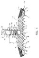
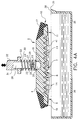
- Figure 1 is a sectioned fragmentary side elevational view of a fluid dispensing apparatus according to the present invention;
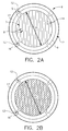
- Figures 2A and 2B are bottom views of the apparatus shown in Figure 1 illustrating preferred embodiments of a lower liquid-supporting surface of the apparatus;
- Figures 3A and 3B are sectioned fragmentary side elevational views of the apparatus shown in Figure 1, illustrating the transfer of a liquid from a source to the liquid-supporting surface of the apparatus of Figures 1 and 2A;
- Figures 4A and 4B are partly sectioned fragmentary side elevational views of the apparatus shown in Figures 1 to 3, illustrating the removal of excess fluid from the liquid-supporting surface prior to the dispensing of fluid on to a test element;
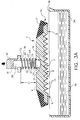
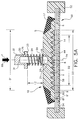
- Figures 5A and 5B are sectioned fragmentary side elevational views of the apparatus shown in Figures 1 to 4 illustrating the instantaneous dispensing of a patient liquid on to the entire test surface of a test element;
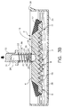
- Figure 6 is a partly sectioned fragmentary side elevational view of the fluid dispensing apparatus shown in Figures 1 to 5 illustrating the dispensing of liquid on to a misaligned test element;
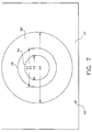
- Figure 7 is a partial top view of the test element shown in Figures 5A and 5B after a liquid has been dispensed thereto illustrating the sizing of a chemistry portion of the test element in accordance with the present invention with that of a known test element; and
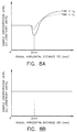
- Figures 8A and 8B are plots illustrating the advantageous features of liquid delivered to a test element using the invention shown by Figures 1 to 7 as compared with prior delivery systems.
- The invention is hereinafter described in the context of the preferred embodiments. In addition, the invention is useful regardless of the liquid being dispensed, the kind of analyzer which is being used, and regardless of whether the surface is a dried slide test element, or even any kind of test element, since the described methods and associated apparatus can also be used to meter on to any surface.
- Terms such as "up", "down", "lower", "vertical", "horizontal", and "bottom" as used herein refer to the orientation of parts when the apparatus is positioned in its customary position of use. The term "surface-dispersed quantity" means, a quantity in which the surface area/volume ratio is approximately 1:1, for example, if a 10cm³ volume has a 10cm² dispersed surface area and a 1cm thickness, its ratio is 1:1. Ratios of 9:10 or 11:10 are included here.
- A preferred embodiment of the present invention is shown in Figures 1, 2A, and 2B.
- Referring to Figure 1, a
transfer element 10 is shown having amain body 2 comprising anupper surface 4 and a preferably circularlower surface 6. The shape oflower surface 6 may be varied, but preferably should be congruent with the shape of the test surface area to be contacted, whatever that may be. - Referring to Figure 2A,
lower surface 6 is defined, in part, by a liquid-supportingportion 7 defined by a series of substantially parallel, V-shapedgrooves 8, disposed over the majority of the area ofsurface 6. The shapes and depths ofgrooves 8, however, may be varied to be rectangular, convex, concave, U-shaped, and so forth. Alternate configurations can also be provided for definingliquid supporting portion 7; for example, a diamond-like pattern such as illustrated in Figure 2B. In the embodiment illustrated in Figures 1 and 2A,grooves 8 have a depth of 200µm and a spacing of 400µm. - Further, liquid-supporting
portion 7 can alternatively be textured (not shown), as opposed to providing grooves, provided capability is provided for supporting a sufficient quantity of liquid to effectively coat the reagent member, or other reactive portion of a test element. -
Lower surface 6 is further defined by aring portion 11, preferably circumferentially and substantially disposed about the entireouter periphery 5 of liquid-supportingportion 7, and having an outerperipheral edge 16. Preferably, ring and liquid-supportingportions ring portion 11 is smooth. Thoughmain body 2, Figure 1, can be constructed of almost any material, it is preferred thatlower surface 6 be made from a compliant and liquid-impermeable material. In the embodiment illustrated,main body 2, includinglower surface 6, is made from a plastic with minimal protein adhesion, such as polypropylene or polyethylene.Ring portion 11 and liquid-supportingportion 7 further define a diameter D1 which is preferably at least equal to the detection or read area of the chemistry portion of a test element. - Referring to Figures 1 and 2A,
grooves 8 are formed insurface 6 betweenring portion 11, to form a series ofribs 14. In the present embodiment,ribs 14 are rounded, though this may not be required iflower surface 6 is made from a fairly compliant material, so as not to damage the chemistry portion of a test element when brought into contact therewith. Contactingsurface 9 ofring portion 11 is made to be flush withribs 14,ring portion 11 being substantially continuous with the exception of a variable number ofsmall vent channels 12. - To absorb excess liquid at the periphery of
surface 6, adisc 17, Figure 1, made of a liquid absorbent material is preferably continuously disposed aboutmain body 2, adjacent outerperipheral edge 16 and generally in contact withring portion 11, except in the vicinity ofvent channels 12, Figure 2, where it is slightly undercut so as not to prematurely siphon liquid fromgrooves 8. Alternately, cross-channels (not shown) arranged substantially perpendicular togrooves 8 can also be provided acrosssurface 6 for this purpose. In the embodiment illustrated,disc 17 is made of a high density open-cell urethane foam, though other nonreactive, liquid absorbing materials such as an absorbent paper may be provided.Disc 17 is made to extend inwardly radially fromedge 16, attaching toupper surface 4. -
Transfer element 10 is preferably made to be both pivotably and vertically movable. Referring to Figure 1, aball 20, is seated within a centrally disposedrecess 18 defined inupper surface 4. Preferably,recess 18 is an opening sized to receiveball 20 and is defined by a substantially orthogonal configuration, having abottom surface 15 and side seating surfaces 21.Ball 20, in the embodiment illustrated, is made of Delrin™, a polyformaldehyde acetal resin sold by E.I. DuPont de Nemours & Company, though other moldable plastics such as polyethylene or polycarbonate are also acceptable. It is preferable, however, thatball 20 be provided with a relatively smooth outer surface for allowingball 20 to be engageably movable withinrecess 18 and along side seating surfaces 21. - One
end 23 of a mountingarm 22 is threaded or otherwise fastened into abore 25 defined inball 20, bore 25 being oppositely situated from the portion ofball 20 which is engaged intorecess 18. The remainingend 27 of mountingarm 22 extends upwardly, in the embodiment illustrated, and is engaged intolower end 29 of a cylindrical supportingmember 26. The other orupper end 31 of supportingmember 26 is inserted into a force-application member 32, having a centrally disposedsleeve 30. In the embodiment illustrated, supportingmember 26 is shaped so as to be slidingly engageable withinsleeve 30. Tobias element 10 to be generally perpendicular toaxis 74, Figure 5A, ahelical spring 24, having a length L1, is positioned betweenupper surface 4 and alower surface 33 offorce application member 32, and is circumferentially disposed about supportingmember 26.Force application member 32 is mechanically attached to an analyzer (not shown). In the embodiment illustrated,ball 20, mountingarm 22,spring 24, supportingmember 26, and forceapplication member 32 can be made part oftransfer element 10, or be part of the analyzer, the remainder of which is not shown. It can be seen that other available means of making the transfer element pivotable can be used, such as by providing supportingmember 26 from a flexible material so as to allow it to bend from a neutral position. - Figures 3A, 3B, 4A, 4B, 5A, 5B and 6 illustrate a method of dispensing a quantity of liquid sample, such as blood serum, on to a test element which permits the quantitative analysis of analytes in the liquid sample using the apparatus discussed above and illustrated in Figures 1 and 2.
- Turning to Figures 3A and 3B,
transfer element 10 is placed into acontainer 34 containing apatient liquid 36. The location and requirements ofcontainer 34 can be varied such that it may be positioned at a station within the confines of a clinical analyzer, or alternatively in an off-line position.Container 34, in terms of location or configuration, is not considered an essential element of the present invention. -
Transfer element 10 is first lowered intocontainer 34, as illustrated in Figure 3B, immersinglower surface 6 to a level in whichgrooves 8 of liquid-supportingportion 7, if present, can acquire containedpatient liquid 36 thereupon. Most of the air contained withingrooves 8 is vented outwardly oftransfer element 10 through ventingchannels 12, Figure 2A.Transfer element 10 is then withdrawn fromcontainer 34. As shown in Figure 4A, astransfer element 10 is removed from container 34 a quantity ofliquid 44 is retained on supportingportion 7, such as withingrooves 8 due to the adhesion of fluid toribs 14. - As
transfer element 10 is withdrawn from container 34 ameniscus 41, containing an excess of patient liquid in addition toquantity 44, Figure 4B required to fillgrooves 8, forms onlower surface 6 due to the surface tension of the patient liquid. It is preferable thatmeniscus 41 be removed prior to the dispensing of liquid fromtransfer element 10 in order to avoid potential flooding of the test slide element when liquid is transferred, and further to more adequately control the volume of liquid to be applied thereto. -
Container 34, preferably, provides means for scraping againstlower surface 6 to wipe excess liquid fromsurface 6 andgrooves 8. Specifically, anedge 38 is provided with aknife edge 35 as shown in Figure 4A and 4B. Beginning at one side of liquid-supportingportion 7,transfer element 10 can be drawn,in the direction ofarrow 42, alongknife edge 35, to removemeniscus 41, Figure 4B, leaving a uniform layer ofpatient liquid 44 withingrooves 8. Aslower surface 6 is drawn acrossknife edge 35 the excessfluid comprising meniscus 41 is squeegeed from one side oflower surface 6 to the other while a quantity offluid 44 withingrooves 8 remains. In addition, the external energy supplied togrooves 8 by scrapingknife edge 35 againstsurface 6 serves to evacuate air pockets formed withingrooves 8, allowing the grooves to fill with liquid. - Any small portion of
meniscus 41 remaining along the outerperipheral edge 16 ofring portion 11 afterlower surface 6 has been drawn alongknife edge 35 can then be wicked by the circumferentially disposedabsorbent disc 17, positioned adjacentouter edge 16. -
Knife edge 35 can be made from known materials. Alternatively, scrapingapparatus 38 can be made part of the analyzer, such as ifcontainer 34 is located off-line. - In this way, a known volume of
liquid material 44, as defined by the size and number ofgrooves 8, is uniformly supported bysurface 6 prior to transferring liquid material to a test element. In the embodiment illustrated, a quantity of 2µl is retained withingrooves 8, over a diameter D1 of 4mm. - Turning to Figures 5A and 5B,
transfer element 10 is positioned over atest element 50 having aplastic support frame 52, and a centrally disposedchemistry portion 58 having a circular configuration, a test volume V subtending test surface area S, and having a diameter D3. Thechemistry portion 58 further comprises dried reagents distributed through twolayers support 54. In the embodiment illustrated, D3 is also 4mm. - Referring to Figures 5A, 5B and 7,
transfer element 10 is lowered untilribs 14 are brought into contact withchemistry portion 58, and specifically,reagent layer 60. As noted above, liquid-supportingportion 7 oflower surface 6 has a diameter D1 which is preferably at least equal to diameter D2, Figure 5B, Figure 7, ofdetection target area 59 ofchemistry portion 58. In the embodiment illustrated,chemistry portion 58 has a diameter D1 of 4mm and detection target area diameter D2 is equal to 3mm. Such equality of diameters removes the need to have horizontal spreading of the liquid across test volume V. - Referring to Figure 5A, downward pressure in the amount of force F is then exerted by
force applicating member 32, as shown byarrow 66, substantially along a vertically extendingcenterline 74. As force F is applied supportingmember 26 is further engaged intosleeve 30 and the distance betweensurface 33 andupper surface 4 is decreased to L2, placinghelical spring 24 into compressive contact withupper surface 4, centrally distributing the applied compressive force F to transferelement 10. The effect of providing compressive force F is that liquid-supportingportion 7 andchemistry portion 58 are also brought into compressive contact. - Under force F, liquid 44 contained within each of
grooves 8 is then uniformly communicated to the entirety of test surface area S of test volume V, effectively blotting the entire test surface area S all at once as a surface-dispersed quantity, as defined, upon removal oftransfer element 10, FIG 5B.Liquid 44 is then quickly absorbed (or vertically diffused) by porous reactant layers 60, 61. The representation in Figure 5B illustrates the instantaneous dispensing of liquid prior to the complete vertical absorption intoporous layers disc 17 is effective in absorbing excess liquid from outerperipheral edge 16 when each of the surfaces are brought into compressive contact, so as not to floodtest element 50.Ring portion 11, having asurface 9 which is flush withedges 14, however, provides a barrier so that only excess liquid is wicked bydisc 17 upon contact. - Figure 6 illustrates an optional pivotability feature of
transfer element 10 in the event that slideelement 50 is not aligned with respect tolower surface 6. According to Figure 6, the position ofslide element 50 defines aplane 70,plane 70 being skewed fromvertical centerline 74 such thatplane 70 is not orthogonal thereto. As liquid-supportingportion 7contacts chemistry portion 58 ofslide element 50 at oneend 72,transfer element 10 is made to pivot aboutcenterline 74 due to downward force F, thereby allowingsurface 6 to align substantially parallel to plane 70 asball 20 impinges upon side surfaces 21 ofrecess 18 allowingtransfer element 10 to rotate counterclockwise, as illustrated byarrow 71, untilsurface 6 contacts end 75. - The compressive load levels applied also insures
chemistry portion 58 will not be damaged. In the embodiment illustrated, a compressive force of 0.14N (0.5ozf) is sufficient to transfer a patient liquid tochemistry portion 58 without damage thereto. The amount of force required, however, can be varied depending upon material properties and the fragility of the chemistry portion provided. In addition, rounding theribs 14 of liquid-supportingportion 7 is also preferable to avoid damage tochemistry portion 58.Transfer element 10 is then withdrawn fromslide test element 50 as illustrated in Figure 5B, byarrow 69. - The method herein described eliminates the need for a spreading layer to horizontally diffuse the patient fluid throughout reagent layers 60, 61 in that the liquid sample has been effectively and uniformly distributed over the entire surface area, all at once, as a surface-dispersed quantity to the test volume V of
element 50 to permit detection of the analyte of interest. Thereby the manufacture of test slide elements, and in particular the manufacture of the chemistry portion contained therein, is simplified. - A direct advantage realized by delivering the liquid sample as a surface-dispersed quantity is graphically illustrated in Figures 8A and 8B. Figure 8A depicts a generalized plot of sample concentration (denoted as C) versus horizontal radial distance from
centerline 74, Figure 5A for a point source dispensing system as typically described above. As noted by the plot, at time t₀ the concentration level C begins to become variable markedly at approximately 2mm, which is approximately the dimension of the pipette tip exterior diameter as the tip vertically delivers the sample as a single droplet to the test element. A variable level of C is thereafter found as R increases outwardly due to the outward spread of the variably viscous sample liquid from the centrally disposed droplet. - At some later time, t₁, there is a tendency for the concentration gradient to equilibrate, or redistribute, to some degree due to diffusion, as represented by the dashed profile. In the embodiment illustrated, t₁ is 1 to 5 minutes, though the time taken to equilibrate, or redistribute can be varied depending upon the diffusivity of compounds used. Such a transient change in the concentration level can directly affect the detection results as read by an analyzer, particularly in rate-type chemistries. Further, the time required for complete equilibration is lengthy and generally unpredictable due to the makeup of individual samples.
- By delivering a surface-dispersed quantity all at once to test volume V, Figure 5A, a relatively constant concentration level C is provided over the entirety of test surface area S, Figure 5A, shown generally by Figure 8B. Further, there is no need for the liquid level delivered to equilibrate and no significant and artificial rate change is produced, such as shown in Figure 8A.
- Referring to Figure 7, a further advantage provided by the present invention is shown. The chemistry portion 58', of a
typical test element 50, having a sample dispensed from a point source (not shown), has a diameter D4 of at least 11mm to provide a detection or readarea 59 having a diameter D2 of 3mm. The present invention, however, by delivering a quantity of patient liquid all at once to an area at least equal todetection area 59 requires asmaller chemistry portion 58. In the embodiment illustrated,chemistry portion 58 has a diameter D3 of 4mm, or roughly the same size D1 oflower surface 6. As noted above, because a much smaller chemistry portion is required, a correspondingly smaller quantity of sample is required to fill the volume. In the embodiment described, approximately 2µl is required to fill thesmaller chemistry portion 58, as opposed to 10µl or more being required for point source dispensing systems having larger chemistry portions. - In another embodiment, a quantity of a liquid diluent can be directly applied all at once to the chemistry portion of a test element using the method and apparatus described herein, prior to the application of a patient sample. This particular embodiment is described in detail in co-pending European patent application no. filed concurrently herewith and corresponding to USSN 094722 filed 21 July 1993 and entitled "Method of Pretreating Diagnostic Test Elements".
Claims (9)
- A method of dispensing a liquid sample on to a test element (50, 52, 54, 60, 61) having a test volume (V) subtending a surface area (S) for that volume for receiving the liquid sample, the method comprising the steps of:-a) applying on to a transfer element (10) having a liquid-supporting surface (7) for supporting a liquid, a quantity of liquid sample over substantially all of the liquid-supporting surface (7); andb) placing the liquid-supporting surface (7) of the transfer element (10) in contact with all of the surface area (S) of a test element (50, 52, 54, 60, 61) at once, thereby transferring the liquid sample as a surface-dispersed quantity to the test element (50, 52, 54, 60, 61) without the need for extensive horizontal flow over the surface area (S) of the test element (50, 52, 54, 60, 61).
- A method according to claim 1, further comprising the step of removing excess liquid material from the liquid-supporting surface (7) of the transfer element (10) prior to step b).
- A liquid dispensing device for dispensing a liquid sample on to a test element (50, 52, 54, 60, 61) having a test surface (S), the device comprising:-
a main body portion (2);
a transfer portion (6, 7, 8) supported by the main body portion (2) for engagement with a test element (50, 52, 54, 60, 61), the transfer portion (6, 7, 8) having a liquid-impermeable supporting surface (7) for supporting a liquid over an area (D1) approximately equal to the area (D3) of the test surface (S) of the test element (50, 52, 54, 60, 61); and
absorbing means (17) disposed about the periphery of the transfer portion (6, 7, 8) for absorbing excess liquid from the liquid-impermeable supporting surface (7) prior to dispensing therefrom. - A device according to claim 3, further comprising pivotable adjusting means (18, 20, 21) for pivotably adjusting the transfer portion (6, 7, 8) to compensate for misalignment with the test surface (S) of a test element (50, 52, 54, 60, 61) ensuring substantial contact therewith for dispensing thereto.
- A device according to claim 4, further comprising biasing means (24) for biasing the transfer portion (6, 7, 8) to be generally perpendicular to a central axis (74), the biasing means (24) cooperating with the pivotable adjusting means (18, 20, 21) to hold the liquid-impermeable supporting surface (7) in contact with the test surface (S) of the test element (50, 52, 54, 60, 61).
- A device according to any one of claims 3 to 5, wherein the liquid-impermeable supporting surface (7) of the transfer portion (6, 7, 8) comprises a plurality of grooves (8) sized to support a quantity of liquid for dispensing.
- A device according to any one of claims 3 to 6, wherein the absorbing means (17) comprises at least one strip of absorbing material, the strip being disposed about at least a portion of the periphery of the transfer portion (6, 7, 8) and in contact with at least a portion of the liquid-impermeable supporting surface (7).
- A device according to any one of claims 3 to 7, further comprising wiping means (35, 38) for wiping excess liquid material from the liquid-impermeabl supporting surface (7) prior to contacting a test element (50, 52, 54, 60, 61).
- A device according to claim 8, wherein the wiping means (35, 38) comprises a knife edge fixture (38) sized so that the liquid-impermeable contacting surface (7) can be scraped against the knife edge fixture (38) to remove excess liquid material prior to contacting with the test element (50, 52, 54, 60, 61).
Applications Claiming Priority (2)
| Application Number | Priority Date | Filing Date | Title |
|---|---|---|---|
| US94724 | 1993-07-21 | ||
| US08/094,724 US5895761A (en) | 1993-07-21 | 1993-07-21 | Surface area liquid transfer method and related apparatus |
Publications (2)
| Publication Number | Publication Date |
|---|---|
| EP0635710A2 true EP0635710A2 (en) | 1995-01-25 |
| EP0635710A3 EP0635710A3 (en) | 1995-04-19 |
Family
ID=22246795
Family Applications (1)
| Application Number | Title | Priority Date | Filing Date |
|---|---|---|---|
| EP94202115A Ceased EP0635710A3 (en) | 1993-07-21 | 1994-07-19 | Method and apparatus for surface area liquid transfer. |
Country Status (3)
| Country | Link |
|---|---|
| US (1) | US5895761A (en) |
| EP (1) | EP0635710A3 (en) |
| JP (1) | JPH07151750A (en) |
Cited By (4)
| Publication number | Priority date | Publication date | Assignee | Title |
|---|---|---|---|---|
| WO1997018036A1 (en) * | 1995-11-13 | 1997-05-22 | Cortecs (Uk) Limited | Diagnostic test apparatus |
| WO2001012328A1 (en) * | 1999-08-17 | 2001-02-22 | Mwg-Biotech Ag | Sample dispenser |
| US6558630B1 (en) | 1997-10-20 | 2003-05-06 | Hans Degn | Dosing unit and a method of continuous introduction of liquid solution samples into a system |
| WO2009134509A2 (en) * | 2008-02-15 | 2009-11-05 | 3M Innovative Properties Company | Sample acquisition device |
Families Citing this family (5)
| Publication number | Priority date | Publication date | Assignee | Title |
|---|---|---|---|---|
| USD412990S (en) | 1996-10-07 | 1999-08-17 | Cortecs (Uk) Limited | Medical test device |
| US9815053B2 (en) * | 2013-01-15 | 2017-11-14 | Mettler-Toledo Rainin, LLC | Liquid end assembly for a multichannel air displacement pipette |
| CN103191794B (en) * | 2013-03-12 | 2015-04-29 | 西安交通大学 | Sample-adding pen and sample-adding method and application thereof |
| USD728120S1 (en) * | 2013-03-15 | 2015-04-28 | Ventana Medical Systems, Inc. | Arcuate member for moving liquids along a microscope slide |
| WO2015189960A1 (en) * | 2014-06-12 | 2015-12-17 | 株式会社 リージャー | Blood-sample collection instrument |
Citations (7)
| Publication number | Priority date | Publication date | Assignee | Title |
|---|---|---|---|---|
| GB2095404A (en) * | 1981-03-25 | 1982-09-29 | Fuji Photo Film Co Ltd | Method for supplying liquid samples to an analysis element |
| EP0075605A1 (en) * | 1981-09-25 | 1983-04-06 | Winfried Dr. med. Stöcker | Apparatus for photometric analyses |
| DE3341518C1 (en) * | 1983-11-17 | 1985-04-18 | Biotest-Serum-Institut Gmbh, 6000 Frankfurt | Method and device for applying a test reagent to a diagnostic test card |
| EP0376110A2 (en) * | 1988-12-28 | 1990-07-04 | Roche Diagnostics GmbH | Test strip analysing system |
| WO1991001364A1 (en) * | 1989-07-24 | 1991-02-07 | Imperial Cancer Research Technology Limited | Sample material transfer device |
| EP0459093A2 (en) * | 1990-05-29 | 1991-12-04 | Becton, Dickinson and Company | Capillary inoculator and assembly for inoculating multiple test sites and method of inoculating test sites therewith. |
| US5143849A (en) * | 1991-03-21 | 1992-09-01 | Eastman Kodak Company | Tip to surface spacing for optimum dispensing controlled by a detected pressure change in the tip |
Family Cites Families (15)
| Publication number | Priority date | Publication date | Assignee | Title |
|---|---|---|---|---|
| US985574A (en) * | 1910-06-17 | 1911-02-28 | Moses B Diskin | Means for applying paste to the coverings for boxes. |
| US1750567A (en) * | 1928-04-16 | 1930-03-11 | Mannington Mills | Apparatus for making mottled floor coverings |
| US2868020A (en) * | 1955-02-24 | 1959-01-13 | Beckman Instruments Inc | Apparatus for applying a liquid sample |
| US3006317A (en) * | 1955-09-08 | 1961-10-31 | Kimberly Clark Co | Knurled strip adhesive applying device |
| US3776184A (en) * | 1972-03-02 | 1973-12-04 | Univ Surrey | Apparatus for applying liquid samples to a surface |
| US3842660A (en) * | 1973-03-19 | 1974-10-22 | Buskirk H Van | Trough applicator |
| US3992158A (en) * | 1973-08-16 | 1976-11-16 | Eastman Kodak Company | Integral analytical element |
| US4086372A (en) * | 1975-10-08 | 1978-04-25 | Helena Laboratories Corporation | Method for applying an organic liquid sample |
| US4367750A (en) * | 1980-11-03 | 1983-01-11 | Levine Robert A | Device for obtaining stool samples |
| US4340390A (en) * | 1980-06-16 | 1982-07-20 | Eastman Kodak Company | Method and apparatus for metering biological fluids |
| US4826759A (en) * | 1984-10-04 | 1989-05-02 | Bio-Metric Systems, Inc. | Field assay for ligands |
| US4615360A (en) * | 1985-09-05 | 1986-10-07 | Eastman Kodak Company | Means providing separation of exterior sheath of liquid on dispensing tip |
| US4906439A (en) * | 1986-03-25 | 1990-03-06 | Pb Diagnostic Systems, Inc. | Biological diagnostic device and method of use |
| FI890105A (en) * | 1988-03-01 | 1989-09-02 | Tobler & Co Ag | ANORDINATION OVER FARING BEHANDLING AV GLIDYTAN I VINTERSPORTARTIKLAR. |
| US4963325A (en) * | 1988-05-06 | 1990-10-16 | Hygeia Sciences, Inc. | Swab expressor immunoassay device |
-
1993
- 1993-07-21 US US08/094,724 patent/US5895761A/en not_active Expired - Lifetime
-
1994
- 1994-07-19 EP EP94202115A patent/EP0635710A3/en not_active Ceased
- 1994-07-21 JP JP6169585A patent/JPH07151750A/en active Pending
Patent Citations (7)
| Publication number | Priority date | Publication date | Assignee | Title |
|---|---|---|---|---|
| GB2095404A (en) * | 1981-03-25 | 1982-09-29 | Fuji Photo Film Co Ltd | Method for supplying liquid samples to an analysis element |
| EP0075605A1 (en) * | 1981-09-25 | 1983-04-06 | Winfried Dr. med. Stöcker | Apparatus for photometric analyses |
| DE3341518C1 (en) * | 1983-11-17 | 1985-04-18 | Biotest-Serum-Institut Gmbh, 6000 Frankfurt | Method and device for applying a test reagent to a diagnostic test card |
| EP0376110A2 (en) * | 1988-12-28 | 1990-07-04 | Roche Diagnostics GmbH | Test strip analysing system |
| WO1991001364A1 (en) * | 1989-07-24 | 1991-02-07 | Imperial Cancer Research Technology Limited | Sample material transfer device |
| EP0459093A2 (en) * | 1990-05-29 | 1991-12-04 | Becton, Dickinson and Company | Capillary inoculator and assembly for inoculating multiple test sites and method of inoculating test sites therewith. |
| US5143849A (en) * | 1991-03-21 | 1992-09-01 | Eastman Kodak Company | Tip to surface spacing for optimum dispensing controlled by a detected pressure change in the tip |
Cited By (8)
| Publication number | Priority date | Publication date | Assignee | Title |
|---|---|---|---|---|
| WO1997018036A1 (en) * | 1995-11-13 | 1997-05-22 | Cortecs (Uk) Limited | Diagnostic test apparatus |
| US6241689B1 (en) | 1995-11-13 | 2001-06-05 | Provalis Uk Limited | Diagnostic test apparatus |
| US6558630B1 (en) | 1997-10-20 | 2003-05-06 | Hans Degn | Dosing unit and a method of continuous introduction of liquid solution samples into a system |
| WO2001012328A1 (en) * | 1999-08-17 | 2001-02-22 | Mwg-Biotech Ag | Sample dispenser |
| US7201880B1 (en) | 1999-08-17 | 2007-04-10 | F. Hoffman-Laroche Ag | Sample dispenser |
| WO2009134509A2 (en) * | 2008-02-15 | 2009-11-05 | 3M Innovative Properties Company | Sample acquisition device |
| WO2009134509A3 (en) * | 2008-02-15 | 2010-01-14 | 3M Innovative Properties Company | Sample acquisition device |
| US8677843B2 (en) | 2008-02-15 | 2014-03-25 | 3M Innovative Properties Company | Sample acquisition device |
Also Published As
| Publication number | Publication date |
|---|---|
| EP0635710A3 (en) | 1995-04-19 |
| JPH07151750A (en) | 1995-06-16 |
| US5895761A (en) | 1999-04-20 |
Similar Documents
| Publication | Publication Date | Title |
|---|---|---|
| US4452899A (en) | Method for metering biological fluids | |
| JP5336179B2 (en) | Separation of diagnostic reagent for diagnostic liquid | |
| US5114862A (en) | Method for distributing and analyzing a fluid sample onto a test surface | |
| US4340390A (en) | Method and apparatus for metering biological fluids | |
| US4737344A (en) | Liquid sample-spotting apparatus | |
| EP0425604B1 (en) | Assay element | |
| US5186897A (en) | Multianalyte test vehicle | |
| EP0163826B1 (en) | Apparatus for removing liquid from the outer surface of a pipette tube | |
| JP3984748B2 (en) | Chemical analyzer and chemical analysis system | |
| US5110555A (en) | Capillary flow apparatus for inoculation of a test substrate | |
| JPH07167779A (en) | Quantitative analysis method of sample liquid | |
| US5895761A (en) | Surface area liquid transfer method and related apparatus | |
| JP2004325462A (en) | Chemical analyzer and chemical analysis system | |
| CA2040920C (en) | Capillary inoculator and assembly for inoculating multiple test sites and method of inoculation test sites therewith | |
| US4928540A (en) | Method of dispensing coagulative test liquid | |
| EP0121863B1 (en) | Automated reagent blotter | |
| EP0635712B1 (en) | Method of pretreating diagnostic test elements | |
| EP0635711B1 (en) | Filtration and dispensing device and method for a liquid | |
| US3606083A (en) | Measuring and transferring apparatus | |
| WO1993015404A2 (en) | Manufacturing process for sample initiated assay device |
Legal Events
| Date | Code | Title | Description |
|---|---|---|---|
| PUAI | Public reference made under article 153(3) epc to a published international application that has entered the european phase |
Free format text: ORIGINAL CODE: 0009012 |
|
| AK | Designated contracting states |
Kind code of ref document: A2 Designated state(s): AT BE CH DE DK FR GB IT LI NL SE |
|
| PUAL | Search report despatched |
Free format text: ORIGINAL CODE: 0009013 |
|
| AK | Designated contracting states |
Kind code of ref document: A3 Designated state(s): AT BE CH DE DK FR GB IT LI NL SE |
|
| RHK1 | Main classification (correction) |
Ipc: G01N 35/00 |
|
| RAP1 | Party data changed (applicant data changed or rights of an application transferred) |
Owner name: CLINICAL DIAGNOSTIC SYSTEMS, INC. |
|
| RAP1 | Party data changed (applicant data changed or rights of an application transferred) |
Owner name: JOHNSON & JOHNSON CLINICAL DIAGNOSTICS, INC. |
|
| 17P | Request for examination filed |
Effective date: 19950929 |
|
| 17Q | First examination report despatched |
Effective date: 19951109 |
|
| GRAG | Despatch of communication of intention to grant |
Free format text: ORIGINAL CODE: EPIDOS AGRA |
|
| STAA | Information on the status of an ep patent application or granted ep patent |
Free format text: STATUS: THE APPLICATION HAS BEEN REFUSED |
|
| 18R | Application refused |
Effective date: 19970114 |