EP0634140A1 - Applicator for tissue adhesive - Google Patents
Applicator for tissue adhesive Download PDFInfo
- Publication number
- EP0634140A1 EP0634140A1 EP94911768A EP94911768A EP0634140A1 EP 0634140 A1 EP0634140 A1 EP 0634140A1 EP 94911768 A EP94911768 A EP 94911768A EP 94911768 A EP94911768 A EP 94911768A EP 0634140 A1 EP0634140 A1 EP 0634140A1
- Authority
- EP
- European Patent Office
- Prior art keywords
- sterile
- gas
- applicator
- pair
- biocompatible adhesive
- Prior art date
- Legal status (The legal status is an assumption and is not a legal conclusion. Google has not performed a legal analysis and makes no representation as to the accuracy of the status listed.)
- Granted
Links
Images


Classifications
-
- A—HUMAN NECESSITIES
- A61—MEDICAL OR VETERINARY SCIENCE; HYGIENE
- A61B—DIAGNOSIS; SURGERY; IDENTIFICATION
- A61B17/00—Surgical instruments, devices or methods, e.g. tourniquets
- A61B17/00491—Surgical glue applicators
-
- A—HUMAN NECESSITIES
- A61—MEDICAL OR VETERINARY SCIENCE; HYGIENE
- A61L—METHODS OR APPARATUS FOR STERILISING MATERIALS OR OBJECTS IN GENERAL; DISINFECTION, STERILISATION OR DEODORISATION OF AIR; CHEMICAL ASPECTS OF BANDAGES, DRESSINGS, ABSORBENT PADS OR SURGICAL ARTICLES; MATERIALS FOR BANDAGES, DRESSINGS, ABSORBENT PADS OR SURGICAL ARTICLES
- A61L26/00—Chemical aspects of, or use of materials for, wound dressings or bandages in liquid, gel or powder form
- A61L26/0061—Use of materials characterised by their function or physical properties
-
- A—HUMAN NECESSITIES
- A61—MEDICAL OR VETERINARY SCIENCE; HYGIENE
- A61B—DIAGNOSIS; SURGERY; IDENTIFICATION
- A61B17/00—Surgical instruments, devices or methods, e.g. tourniquets
- A61B17/00491—Surgical glue applicators
- A61B2017/00495—Surgical glue applicators for two-component glue
Definitions
- the present invention relates to an applicator for applying a biocompatible adhesive, containing human or animal protein as a principal ingredient, to a human or animal body, and is more particularly to an applicator for spraying the biocompatible adhesive so as to apply it to a surgical site.
- This applicator is preferably used for applying the biocompatible adhesive for hemostasis of bleeding onto a resected surface of liver or lung, or a surgically sutured site of a digestive gagt.
- a biocompatible adhesive mainly based on human or animal protein is generally prepared in situ by mixing a protein solution with another coagulating solution containing a coagulation factor which promotes coagulation of the protein.
- the biocompatible adhesive of this kind which, for example, is a mixture of a solution containing both factor XIII and fibrinogen with another solution containing thrombin, one of two following methods are generally used in the art: To apply the first mentioned solution to the surgical site and then coating the same with the second mentioned solution, and to premix the two solutions together before the resultant mixture is applied to the surgical site by the use of a syringe.
- the applicator for applying the biocompatible adhesive described in the Japanese Utility Model Publication No. 3-47609 includes a conflux head having defined therein a pair of conveying channels for conveying two solutions, respectively, which are discharged from associated conical portions, or nozzles of the syringes.
- the applicator also includes a pair of sterile gas supply channels, which are so arranged in the vicinity of respective outlets of the conveying channels as to lie at right angle to the conveying channels.
- the sterile gas nozzles have their longitudinal axes arranged to intersect with each other at a location spaced a specific distance away from the outlets of the sterile gas nozzles.
- this prior art applicator has the following problems. For example, since the conveying channels lies at substantially right angles to the sterile gas supply channels, that is, they do not direct to the surgical site, if the sterile gas has a low pressure, the adhesive will not be applied properly to the surgical site, or will not be sprayed in uniform density. On the other hand, if the sterile gas of a high pressure is supplied, it may possibly bring about harmful influence upon the surgical site. Also, the distance between the two outlets of the nozzles are so large that these solutions will mix together at a location spaced a distance of about 10 to 20 cm from those outlets. Therefore, the applicator is not available for application of the adhesive to the surgical site which is deep and narrow.
- the sterile gas is introduced through a long tube from a sterile gas supply unit or a cylinder containing a highly pressurized sterile gas.
- the long tube and/or the cylinder may disturb a surgical job being performed which would cause a loss of surgical operation and a reduction in result of surgical operations.
- Another object of the present invention is to provide an improved applicator of the type referred to above which can be easily transported and handled during the performance of an surgical operation.
- a further object of the present invention is to provide an improved applicator of the type referred to above which does not make use of any long sterile gas supply tube.
- an applicator for applying a biocompatible adhesive containing human or animal protein as a principal ingredient to a surgical site of living body comprises a spray head which includes a housing to which a sterile gas is supplied; a sterile-gas supply tube connected to the housing for supplying the sterile gas thereto; a pair of adjacent sterile-gas ejecting nozzles having their longitudinal axes oriented in the same direction for guiding and ejecting the sterile gas supplied to the housing in the same direction; a pair of adapters to which respective nozzles of syringe barrels are connected; and a pair of solution tube, each of which has one end thereof connected to the adapter and the other end thereof protruded a predetermined distance outwardly from the sterile gas ejection nozzle through an interior of the housing.
- respective solutions supplied from the syringes via the barrel adapters are ejected from the outlets of the solution tubes, while the sterile gas supplied to the sterile-gas supply chamber through the sterile-gas supply tubes is ejected from the sterile-gas ejection nozzles in the substantially same direction. Consequently, the solutions are sprayed and mixed by the ejection of the sterile gas.
- an applicator of the present invention includes a holder for holding two syringe barrels which accommodate a protein solution and a solution of coagulation factor which promotes coagulation of protein, respectively; an actuator for holding and simultaneously moving syringe plungers inserted in respective barrels; and a spray head for spraying the two solutions discharged from the respective syringe.
- the spray head includes a sterile-gas supply chamber, a sterile-gas supply tube connected at one end thereof to the sterile-gas chamber for feeding a sterile-gas to the sterile-gas supply chamber, a pair of adjacent sterile-gas ejection nozzles having their longitudinal axes oriented in the same direction for guiding and ejecting the sterile gas supplied the sterile-gas supply chamber in same direction, a pair of adapters to which the respective syringe barrels are connected, and a pair of solution tubes each connected at one end thereof to the adapter through an interior of the sterile-gas supply chamber, each of said solution tubes having the opposite end protruding a predetermined distance outwardly from the sterile gas ejection nozzles.
- the sterile gas supplied to the sterile-gas supply chamber through the sterile-gas supply tubes are ejected from the sterile-gas ejecting nozzles in a predetermined direction.
- the solutions accommodated in the pair of syringes are fed to the solution tubes by biasing the actuator and pushing the respective plungers into the barrels, and then ejected from outlets of the solution tubes.
- the two ejected solutions are sprayed by the sterile gas ejected therearound, and mixed together.
- each of the sterile-gas ejecting nozzles further has its inner periphery surface formed with a plurality of ribs for supporting the associated solution tube in coaxial relationship therewith.
- this applicator incorporates the sterile-gas supply means, switching means and so forth, it is convenient for transportation during the surgical operation and handling. Further, since it is unnecessary to use a long tube for introducing the sterile gas from the pressurized gas source, the applicator ensures a rather safe operation. Furthermore, the solutions may be sprayed uniformly. Moreover, ejection of the sterile gas is permitted only by controlling the switching means, which results in efficient use of the sterile gas.
- a distance between the pair of solution tubes is chosen to be about 1 to 20 mm, preferably about 1 to 5 mm.
- a length of the distal end of each solution tube which protrudes outwardly from the sterile-gas ejection nozzle is chosen to be about 0.1 to 10 mm.
- the spray head has an elongated hollow extension of an approximate length of 5 to 50 cm, the distal end thereof being formed with a pair of through-holes through which respective solution tubes extending into the extension through the rear end portion of such extension are guided so as to protrude outwardly from the extension. This permits a spraying of the solutions against a deep and/or narrow surgical site.
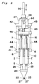
- FIG. 1 there is shown an applicator for applying a biocompatible adhesive according to a first embodiment of the present invention.
- the applicator indicated generally by reference numeral 1 comprises a pair of syringes 2 for accommodating fibrinogen and thrombin solutions, respectively.
- Each syringe 2 includes a barrel 3 which comprises a cylindrical body 4, a nozzle 5 at one end of the body 4, and a terminal flange 6 projecting radially outwardly at the other end of the body 4.
- a plunger 7 for each syringe 2 carries at one end thereof a packing 8 which is made of elastic material such as rubber. This packing 8 has a diameter slightly larger than inner diameter of the body 4.
- each plunger 7 is formed integrally with a thumb yoke or finger engaging head 9.
- the plunger 7 is inserted into the respective barrel 3 with slidingly situated within the body 4 so that an outer peripheral surface of the packing 8 snugly contacts an inner peripheral surface of the cylindrical body 4.
- the barrel 3 and the plunger 7 are generally made of glass or transparent synthetic resin such as polypropylene or polycarbonate.
- a syringe holder 10 for supporting these barrels 3 together is preferably made of synthetic resin such as, for example, polyethylene, polypropylene, acrylonitrile-butadiene-styrene copolymer or polycarbonate, and includes a pair of parallel concave portions 11.
- Each concave portion 11 has a C-shaped internal surface at a curvature complemental to that of the outer periphery of the associated cylindrical body 4.
- An upper end of the concave portion 11 is so designed as to have a slightly greater width than external diameter of the cylindrical body 4, which ensures the concave portion 11 to tightly retain the barrel 3 therein.
- the opening width of the concave portion 11 is determined by taking both resistance for attachment of the barrel 3 and stability of the same held in the concave portion 11 into consideration.
- the holder 10 further comprises a stopper 13 facing but spacing a predetermined distance from one end of a connecting portion 13 defining a wall between the pair of concave portions 11, such that the flanges 6 of the barrels 3 held in the respective concave portions 11 are inserted into a gap, i.e., concave portion 15 formed between the stopper 13 and an end surface 14 confronting thereto for fixing the flanges.
- An actuator 16 for simultaneously moving the syringe plungers 7 inserted in the barrel 3, is preferably made of same material as the holder 10, and comprises a front wall 17, and a rear wall 18 facing forwards, and spaced a predetermined distance from the front wall 17.
- the front wall 17 has a pair of recesses 19 cut away inwardly so as extending downwardly, and spaced a distance on pitch equal to that between the concave portions 11 in the holder 10.
- a spray head 20 for spraying the fibrinogen and thrombin solutions discharged from the respective syringes 2 comprises, as shown in detail in Figs. 4 and 5, a hollow housing 21 of a flattened truncated-pyramid or truncated-cone configuration.
- the housing 21 has at a front portion thereof a pair of parallel nozzles 22 for ejecting a sterile gas.
- Each nozzle 22 has its inner peripheral surface formed with a plurality of axial ribs 23 projecting radially inwardly therefrom so as to define a respective channel 24 surrounded by the axial ribs 23 for guiding an associated tube as will be described later.
- the housing 21 also comprises at a rear end portion thereof a pair of cylindrical syringe connectors 25 to which respective nozzle adapters 26 having a generally conical configuration are inserted so that the syringe nozzles 5 will be fitted in from rear openings thereof.
- Each nozzle adapter 26 has an inner end fluid-coupled with one end of the associated tube 27 housed within the housing 21.
- Each tube 27 fluid-coupled with the nozzle adapter 26 extends through the associated channel 24 with its distal end protruding outwardly from the nozzle 22.
- the length of the distal end of each tube 27 which protrudes outwardly from the nozzle 24 is chosen to be about 0.1 to 10 mm to ensure that the solutions ejected from the tubes 27 will be sprayed uniformly by the sterile gas emitted from the nozzles 22.
- a bottom portion of the housing 21 has a gas supply tube 28 connected thereto so as to communicate with the interior of the housing 21.
- the gas supply tube 28 includes a sterilizing filter 29 (see Fig. 3) for sterilizing the gas fed from a pressurized gas source (not shown) before the gas is introduced into the housing 21.
- a sterilizing filter 29 for sterilizing the gas fed from a pressurized gas source (not shown) before the gas is introduced into the housing 21.
- vinyl chloride tube is suited for the sterile gas supply tube.
- the filter 29 is the form of MILLEX FG available from Millipore Corp. of U.S.A.
- an amount of the fibrinogen solution is filled in one syringe 2, and an equal amount of the thrombin solution is accommodated in the other syringe 2.
- the syringes 2 are then fitted in the respective concave portions 11 of the holder 10, while the flanges 6 are inserted in the recesses 15.
- the width of the uppermost opening of the recess 11 is set to be smaller than the external diameter of the barrel 3 so that the barrel 3 fitted is held tightly, which prevents the barrel 3 from moving or dropping therefrom.
- the thumb yoke 9 of the plungers 7 are inserted between the front and rear walls 17 and 18 of the actuator 16, and besides, the rear portions of the plungers 7 are engaged in the concave portions 19.
- the distance between the front and rear walls 17 and 18 is preferably so chosen as to be substantially equal to the thickness of thumb yokes 9. This ensures that the actuator 16 holds the plungers 7 without no play.
- the sterile gas supply tube 28 is connected to a tube (not shown) used to fluid-connected it with the pressurized gas source.
- the sterile gas is fed from the sterile gas source through the sterile gas supply tube into the housing 21 and is then ejected from the nozzles 22.
- the solutions are ejected from the solution tube 27, by the application of an external push from the thumb finger of the user to the rear surface of the actuator 16 while the holder 10 and/or the flanges 6 is held between two fingers, i.e., fore- and middle-fingers.
- the solutions ejected from the tubes 27 are sprayed by the sterile gas ejected therearound, diffused and mixed together in the sterile gas, and are then applied to the surgical site.
- the solution tubes 27 are retained stably by the surrounding axial ribs 23, which keeps the directions of the ejected solutions. This ensures that the solutions are applied exactly to the surgical site at which the nozzles are aimed.
- Fig. 6 shows a modified form of the applicator.
- the applicator shown therein includes a spray head 30 having an elongated extension 31 of an approximate length of 5 to 50 cm so that the biocompatible adhesive can be applied to the surgical site which is relatively deep from the skin and visible to the naked eye or with an endoscope.
- the extension 31 is in the form of a hollow cylindrical pipe having a round or elliptic cross-section and closed at its opposite ends. This extension 31 has its interior fluid-connected with the sterile gas supply tube 32. As shown in Fig.
- the tube 32 has a distal end 33 formed with a pair of through-holes or nozzles 34, through which respective solution tubes 36 extending into the extension 31 through a rear end plate 35 of such extension 31 are guided so as to protrude outwardly from the nozzles 34.
- each nozzle 34 preferably has its inner peripheral surface formed with a plurality of ribs projecting radially inwardly for supporting the associated solution tube 36 in coaxial relationship therewith.
- FIG. 8 there is shown the hollow spray head of the type shown in Figs. 1 to 5, which incorporates an elongated hollow extension 40 at the distal end thereof.
- this type of spray head it is possible to spray the adhesive to the deep surgical site treated by the use of a peritoneoscope.
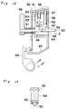
- a gun-type applicator for applying a biocompatible adhesive is generally shown by 41.
- This gun-type applicator 41 comprises, in addition to a holder 10 and an actuator 16, a feed mechanism 42 which supports the holder 10 and the actuator 16. This feed mechanism 42 automatically moves the actuator 16 towards the holder 10.
- the feed mechanism 42 includes a frame 43 which is coupled to one ends of two parallel guide rods 44 spaced a predetermined distance therebetween.
- the other ends of the guide rods 44 are coupled to a connecting member 45 detachably carrying the holder 10.
- Axially slidably mounted on these guide rods 44 is a pushing member 46 which holds actuator 16 detachably.
- the frame 43 has a braking box 47 mounted thereon.
- This braking box 47 has through-holes 48 and 49 defined in its forward and backward walls, respectively.
- a pressure rod 50 Inserted in the through-holes 48 and 49 is a pressure rod 50 which extends parallel to the guide rods 44 and is fixed at its front end to the pushing member 46.
- a spring 51 Arranged between the braking box 47 and the pushing member 46 is a spring 51 operable to bias the pushing member 46 forwardly. An actual forward push of the pushing member 46 by the spring 51 takes place when a switching mechanism 52 described hereinafter is activated.
- the switching mechanism 52 comprises a braking member 54 disposed in the braking box 47.
- the braking member 54 is rotatablly supported about a shaft 53 extending perpendicular to the pressure rod 50 and is provided with a friction member 55 frictionally engageable with the pressure rod 50 (see Fig. 13).
- a surface area of the pressure rod 50 which is brought into contact with the friction member 55 is formed with surface irregularities so that a greater force of friction will be generated between the friction member 55 and the pressure rod 50.
- Rotatablly coupled to the braking member 54 is a rod 58 extending through a through-hole 57 formed in the upper wall 56 of the braking box 47.
- This rod 58 carries on its periphery a helical spring 59 operable to bias the rod 58 so as to bring the friction member 55 into frictional contact with the pressure rod 50.
- a connecting member 60 Arranged above the upper and front surfaces of the braking box 47 is a connecting member 60 to which an end portion of the rod 58 protruding outwardly from the braking box 47 is engaged
- a rod 63 extending through a hole 61 defined in the upper wall 56 of the braking box 47 is connected to the connecting member 60.
- the rod 63 has a helical spring 62 mounted therearound so that the connecting member 60 is normally urged downward by the biasing force of the spring 62.
- the connecting member 60 is rotatablly coupled to a switching means, that is, a switching lever 64 rotatablly supported on the frame 43. Therefore, upon moving the switching lever 64 in a direction indicated by the arrow X, the connecting member 60 is raised to rotate the braking member 54 in a direction indicated by the arrow Y, which permits the pressure rod 50 to move in a direction indicated by the arrow Z by the action of the biasing force of the spring 51. On the other hand, upon releasing the switching lever 64, by the action of the biasing force of the springs 59 and 62, the connecting member 60 descends so as to rotate the braking member 54 in a direction indicated by the arrow Y', which brings the pressure rod 50 to a halt.
- a switching lever 64 upon moving the switching lever 64 in a direction indicated by the arrow X, the connecting member 60 is raised to rotate the braking member 54 in a direction indicated by the arrow Y, which permits the pressure rod 50 to move in a direction indicated by the arrow Z by the action
- the switching lever 64 has not only a function to control the movement of the pressure rod 50 in the direction indicated by the arrow Z, that is, the forward movement, as described before, but also another function to control the supply of the sterile gas from a sterile-gas supply unit 65 which will be discussed below.
- the sterile gas supply unit 65 comprises a gas holder 66.
- This gas holder 66 is fixed to the frame 43 and serves as a grip for users. Therefore, in operation, the user holds the grip and engages his finger on the switching lever 64 to activate it.
- the gas holder 66 houses a miniature gas cylinder 67, the pressure of the gas ejected from the cylinder 67 being adjusted by a small-sized high-pressure regulator 68.
- An outlet of the gas cylinder 67 is connected to a connecting tube 69 so that gas accommodated in the gas cylinder 67 can be fed through the connecting tube 69 and another tube 71 connected thereto to the gas supply tube 28.
- the connecting tube 69 is incorporated with a valve 70 so that, upon moving the switching lever 64 in the direction indicated by arrow X, the valve 70 changes its position from a closed state to an opened state.
- a gas cylinder 67 it is advantageous to use Mini Gas-Cartridge M-1509-EW-Cn2R available from NIPPON TANSAN GAS Co., LTD.
- the high pressure regulator 68 it is preferable to employ one, such as Gas Supply Unit NR-01 available from NIPPON TANSAN GAS Co., LTD., whose discharging pressure can be controlled within 0.5 - 4.0 kg/cm2.
- Fibrinogen and thrombin solutions of the same amount are drawn into respective syringes 2. These syringes are fitted to the holder 10 while the thumb yokes 9 of the plungers 7 are housed in the actuator 16. Then, after moving the pressure rod 50 backward against the biasing force of the spring 51, the holder 10 is coupled to the connecting member 45 and, at the same time, the actuator 16 is coupled to the pushing member 46. Further, the spray head 20 is connected to the nozzles 5 of the syringes 2, while the sterile-gas supply tube 28 is connected through the extension tube 71 to the connecting tube 69.
- the user grips the gas holder 66 with his forefinger engaged in the switching lever 64, directs the front nozzles 22 of the spray head 20 to the surgical site, and moves the switching lever 64 in the direction indicated by the arrow X.
- the valve 70 is changed from the closed position to the opened position according to the movement of the switching lever 64, such that the gas accommodated in the gas cylinder 67 is supplied through the connecting tube 69 and extension tube 71 to the filter 29, where it is sterilized, and is then ejected from the nozzle 22 through the housing 21 towards the surgical sites.
- the connecting member 60 and rods 58 and 63 move upward and the braking member 54 releases the rod 50 to move.
- the pressure rod 50 moves forward, i.e., in the direction indicated by the arrow Z by the biasing force of the spring 51, and pushes the actuator 16 and plungers 7 through the pushing member 46.
- the solutions accommodated in the syringes 2 are ejected from the solution tubes 27, sprayed and mixed by the ejected sterile gas, and then applied onto the surgical site uniformly.
- the sterile gas can be ejected simultaneously with the solutions, it is preferable to design the applicator that, upon moving the switching lever 64 in the direction indicated by arrow X, the sterile gas is ejected and then the solution is permitted to eject by the further movement of the switching lever 64 in the same direction.
- Spraying of the solutions can be suspended only by releasing the switching lever 64.
- the connecting member 60 moves downward, so that the braking member 50 presses the pressure rod 50 to prevent it from moving forward.
- the switching lever 64 moves in a direction indicated by the arrow X' so that the valve changes from the opened position to the closed position, which eventually interrupts the supply of the gas from the gas cylinder 67. Accordingly, the amount of the solutions sprayed to the surgical site can readily be controlled by changing the position of the switching lever.
- the gun-type applicator for applying the biocompatible adhesive incorporates the gas cylinder 67, it has advantages that transportation during the surgical operation can easily be done, the direction of spray of the adhesive can freely be changed, and a change between operating state and non-operating state can readily be done by one hand.
Abstract
Description
- The present invention relates to an applicator for applying a biocompatible adhesive, containing human or animal protein as a principal ingredient, to a human or animal body, and is more particularly to an applicator for spraying the biocompatible adhesive so as to apply it to a surgical site. This applicator is preferably used for applying the biocompatible adhesive for hemostasis of bleeding onto a resected surface of liver or lung, or a surgically sutured site of a digestive truct.
- A biocompatible adhesive mainly based on human or animal protein is generally prepared in situ by mixing a protein solution with another coagulating solution containing a coagulation factor which promotes coagulation of the protein. When applying to a surgical site the biocompatible adhesive of this kind which, for example, is a mixture of a solution containing both factor XIII and fibrinogen with another solution containing thrombin, one of two following methods are generally used in the art: To apply the first mentioned solution to the surgical site and then coating the same with the second mentioned solution, and to premix the two solutions together before the resultant mixture is applied to the surgical site by the use of a syringe.
- These methods suffer from several drawbacks. For example, in the first mentioned method, surface hardening takes place before the two solutions are completely mixed together, which resulting in insufficient mixing and reduction of the adhesive strength. In the second mentioned method, since the hardening of the adhesive starts soon after mixing the two solutions, it is necessary to apply the adhesive to the surgical site immediately after the mixing. For this reason, this second mentioned method does not only require considerable surgical skill, but also limits its application.
- To solve these problems, a method for accommodating those two solutions in syringes separately, ejecting the solutions simultaneously from the respective syringes so as to mix together and apply the resultant mixture to the surgical site, has been suggested in the Japanese Patent Laid-Open Publications No. 64-25843 and No. 64-4040, Japanese Utility Model Laid-Open Publication No. 62-62674, 62-62675, No. 62-65972, No. 62-65973, No. 62-20853, No. 1-82049, and Japanese Utility Model Publication No.3-47609.
- The applicator for applying the biocompatible adhesive described in the Japanese Utility Model Publication No. 3-47609 includes a conflux head having defined therein a pair of conveying channels for conveying two solutions, respectively, which are discharged from associated conical portions, or nozzles of the syringes. The applicator also includes a pair of sterile gas supply channels, which are so arranged in the vicinity of respective outlets of the conveying channels as to lie at right angle to the conveying channels. Further, the sterile gas nozzles have their longitudinal axes arranged to intersect with each other at a location spaced a specific distance away from the outlets of the sterile gas nozzles.
- However, this prior art applicator has the following problems. For example, since the conveying channels lies at substantially right angles to the sterile gas supply channels, that is, they do not direct to the surgical site, if the sterile gas has a low pressure, the adhesive will not be applied properly to the surgical site, or will not be sprayed in uniform density. On the other hand, if the sterile gas of a high pressure is supplied, it may possibly bring about harmful influence upon the surgical site. Also, the distance between the two outlets of the nozzles are so large that these solutions will mix together at a location spaced a distance of about 10 to 20 cm from those outlets. Therefore, the applicator is not available for application of the adhesive to the surgical site which is deep and narrow.
- In addition, the sterile gas is introduced through a long tube from a sterile gas supply unit or a cylinder containing a highly pressurized sterile gas. The long tube and/or the cylinder may disturb a surgical job being performed which would cause a loss of surgical operation and a reduction in result of surgical operations.
- It is therefore an object of the present invention to provide an improved applicator for applying a biologically compatible adhesive, which is effective to spray the adhesive to the surgical site even though the sterile gas is low in pressure.
- Another object of the present invention is to provide an improved applicator of the type referred to above which can be easily transported and handled during the performance of an surgical operation.
- A further object of the present invention is to provide an improved applicator of the type referred to above which does not make use of any long sterile gas supply tube.
- To achieve the objects in accordance with the purpose of the invention, an applicator for applying a biocompatible adhesive containing human or animal protein as a principal ingredient to a surgical site of living body comprises a spray head which includes a housing to which a sterile gas is supplied; a sterile-gas supply tube connected to the housing for supplying the sterile gas thereto; a pair of adjacent sterile-gas ejecting nozzles having their longitudinal axes oriented in the same direction for guiding and ejecting the sterile gas supplied to the housing in the same direction; a pair of adapters to which respective nozzles of syringe barrels are connected; and a pair of solution tube, each of which has one end thereof connected to the adapter and the other end thereof protruded a predetermined distance outwardly from the sterile gas ejection nozzle through an interior of the housing.
- According to the applicator, respective solutions supplied from the syringes via the barrel adapters are ejected from the outlets of the solution tubes, while the sterile gas supplied to the sterile-gas supply chamber through the sterile-gas supply tubes is ejected from the sterile-gas ejection nozzles in the substantially same direction. Consequently, the solutions are sprayed and mixed by the ejection of the sterile gas.
- Another embodiment of an applicator of the present invention includes a holder for holding two syringe barrels which accommodate a protein solution and a solution of coagulation factor which promotes coagulation of protein, respectively; an actuator for holding and simultaneously moving syringe plungers inserted in respective barrels; and a spray head for spraying the two solutions discharged from the respective syringe. The spray head includes a sterile-gas supply chamber, a sterile-gas supply tube connected at one end thereof to the sterile-gas chamber for feeding a sterile-gas to the sterile-gas supply chamber, a pair of adjacent sterile-gas ejection nozzles having their longitudinal axes oriented in the same direction for guiding and ejecting the sterile gas supplied the sterile-gas supply chamber in same direction, a pair of adapters to which the respective syringe barrels are connected, and a pair of solution tubes each connected at one end thereof to the adapter through an interior of the sterile-gas supply chamber, each of said solution tubes having the opposite end protruding a predetermined distance outwardly from the sterile gas ejection nozzles.
- According to this applicator, the sterile gas supplied to the sterile-gas supply chamber through the sterile-gas supply tubes are ejected from the sterile-gas ejecting nozzles in a predetermined direction. The solutions accommodated in the pair of syringes are fed to the solution tubes by biasing the actuator and pushing the respective plungers into the barrels, and then ejected from outlets of the solution tubes. As a result, the two ejected solutions are sprayed by the sterile gas ejected therearound, and mixed together.
- Preferably, each of the sterile-gas ejecting nozzles further has its inner periphery surface formed with a plurality of ribs for supporting the associated solution tube in coaxial relationship therewith.
- Other embodiment of the applicator of the present invention includes means for supporting a holder which holds a pair of syringe barrels; means for pushing an actuator which holds syringe plungers inserted in respective syringe barrels; a sterile gas supply source for supplying a sterile gas to a sterile-gas supplying tubes;
switching means for controlling the sterile-gas supply means and the pushing means. - Since this applicator incorporates the sterile-gas supply means, switching means and so forth, it is convenient for transportation during the surgical operation and handling. Further, since it is unnecessary to use a long tube for introducing the sterile gas from the pressurized gas source, the applicator ensures a rather safe operation. Furthermore, the solutions may be sprayed uniformly. Moreover, ejection of the sterile gas is permitted only by controlling the switching means, which results in efficient use of the sterile gas.
- Further, in another embodiment, a distance between the pair of solution tubes is chosen to be about 1 to 20 mm, preferably about 1 to 5 mm.
- Furthermore, in other embodiment, a length of the distal end of each solution tube which protrudes outwardly from the sterile-gas ejection nozzle is chosen to be about 0.1 to 10 mm. As a result, the solution tubes will not clog even though the spraying of the solutions are interrupted, such that turning on and off the spraying may be permitted.
- Moreover, the spray head has an elongated hollow extension of an approximate length of 5 to 50 cm, the distal end thereof being formed with a pair of through-holes through which respective solution tubes extending into the extension through the rear end portion of such extension are guided so as to protrude outwardly from the extension. This permits a spraying of the solutions against a deep and/or narrow surgical site.
-
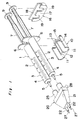
- Fig.1 is an exploded view of an adhesive applicator according to the present invention;
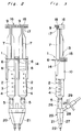
- Fig.2 is a plan view of the adhesive applicator in an assembled condition;
- Fig.3 is a view similar to Fig. 2 showing the adhesive applicator as viewed from a direction with the applicator turned 90° relative to that shown in Fig. 2;
- Fig.4 is a top sectional view of a spray head shown in Fig. 1;
- Fig.5 is a side sectional view of the spray head;
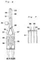
- Fig.6 is a plan view of the adhesive applicator in which an elongated tube is fitted to the spray head;
- Fig. 7 is a partial cross sectional view, on an enlarged scale, of a distal end portion of the tube shown in Fig.6;
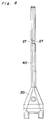
- Fig. 8 is a plan view showing a modified form of the elongated tube fitted to the spray head;
- Fig. 9 is a plan view of the adhesive applicator according to another embodiment of the present invention;
- Fig. 10 is a side elevational view of the adhesive applicator shown in Fig. 9 with a guide rod removed;
- Fig. 11 is a side elevational view of the applicator shown in Fig. 9 ,in which the guide rod, syringes, spray head and sterile-gas supply tube are removed;
- Fig. 12 is a sectional view, on an enlarged scale, of the adhesive applicator shown in Fig.9; and
- Fig. 13 is a sectional view of a pushing rod and a stopper brought into contact with each other.
- Referring first to Figs. 1 to 3, there is shown an applicator for applying a biocompatible adhesive according to a first embodiment of the present invention. The applicator indicated generally by reference numeral 1 comprises a pair of
syringes 2 for accommodating fibrinogen and thrombin solutions, respectively. Eachsyringe 2 includes abarrel 3 which comprises acylindrical body 4, anozzle 5 at one end of thebody 4, and aterminal flange 6 projecting radially outwardly at the other end of thebody 4. Aplunger 7 for eachsyringe 2 carries at one end thereof apacking 8 which is made of elastic material such as rubber. Thispacking 8 has a diameter slightly larger than inner diameter of thebody 4. The other end of eachplunger 7 is formed integrally with a thumb yoke orfinger engaging head 9. Theplunger 7 is inserted into therespective barrel 3 with slidingly situated within thebody 4 so that an outer peripheral surface of thepacking 8 snugly contacts an inner peripheral surface of thecylindrical body 4. Thebarrel 3 and theplunger 7 are generally made of glass or transparent synthetic resin such as polypropylene or polycarbonate. - A
syringe holder 10 for supporting thesebarrels 3 together is preferably made of synthetic resin such as, for example, polyethylene, polypropylene, acrylonitrile-butadiene-styrene copolymer or polycarbonate, and includes a pair of parallelconcave portions 11. Eachconcave portion 11 has a C-shaped internal surface at a curvature complemental to that of the outer periphery of the associatedcylindrical body 4. An upper end of theconcave portion 11 is so designed as to have a slightly greater width than external diameter of thecylindrical body 4, which ensures theconcave portion 11 to tightly retain thebarrel 3 therein. Preferably, the opening width of theconcave portion 11 is determined by taking both resistance for attachment of thebarrel 3 and stability of the same held in theconcave portion 11 into consideration. Theholder 10 further comprises astopper 13 facing but spacing a predetermined distance from one end of a connectingportion 13 defining a wall between the pair ofconcave portions 11, such that theflanges 6 of thebarrels 3 held in the respectiveconcave portions 11 are inserted into a gap, i.e.,concave portion 15 formed between thestopper 13 and anend surface 14 confronting thereto for fixing the flanges. - An
actuator 16, for simultaneously moving thesyringe plungers 7 inserted in thebarrel 3, is preferably made of same material as theholder 10, and comprises afront wall 17, and arear wall 18 facing forwards, and spaced a predetermined distance from thefront wall 17. Thefront wall 17 has a pair ofrecesses 19 cut away inwardly so as extending downwardly, and spaced a distance on pitch equal to that between theconcave portions 11 in theholder 10. - A
spray head 20 for spraying the fibrinogen and thrombin solutions discharged from therespective syringes 2 comprises, as shown in detail in Figs. 4 and 5, ahollow housing 21 of a flattened truncated-pyramid or truncated-cone configuration. Thehousing 21 has at a front portion thereof a pair ofparallel nozzles 22 for ejecting a sterile gas. Eachnozzle 22 has its inner peripheral surface formed with a plurality ofaxial ribs 23 projecting radially inwardly therefrom so as to define arespective channel 24 surrounded by theaxial ribs 23 for guiding an associated tube as will be described later. - The
housing 21 also comprises at a rear end portion thereof a pair ofcylindrical syringe connectors 25 to whichrespective nozzle adapters 26 having a generally conical configuration are inserted so that thesyringe nozzles 5 will be fitted in from rear openings thereof. Eachnozzle adapter 26 has an inner end fluid-coupled with one end of the associatedtube 27 housed within thehousing 21. Eachtube 27 fluid-coupled with thenozzle adapter 26 extends through the associatedchannel 24 with its distal end protruding outwardly from thenozzle 22. Preferably, the length of the distal end of eachtube 27 which protrudes outwardly from thenozzle 24 is chosen to be about 0.1 to 10 mm to ensure that the solutions ejected from thetubes 27 will be sprayed uniformly by the sterile gas emitted from thenozzles 22. - A bottom portion of the
housing 21 has agas supply tube 28 connected thereto so as to communicate with the interior of thehousing 21. Thegas supply tube 28 includes a sterilizing filter 29 (see Fig. 3) for sterilizing the gas fed from a pressurized gas source (not shown) before the gas is introduced into thehousing 21. Generally, vinyl chloride tube is suited for the sterile gas supply tube. Preferably, thefilter 29 is the form of MILLEX FG available from Millipore Corp. of U.S.A. - In assembling the applicator, for example, an amount of the fibrinogen solution is filled in one
syringe 2, and an equal amount of the thrombin solution is accommodated in theother syringe 2. Thesyringes 2 are then fitted in the respectiveconcave portions 11 of theholder 10, while theflanges 6 are inserted in therecesses 15. The width of the uppermost opening of therecess 11 is set to be smaller than the external diameter of thebarrel 3 so that thebarrel 3 fitted is held tightly, which prevents thebarrel 3 from moving or dropping therefrom. Thethumb yoke 9 of theplungers 7 are inserted between the front andrear walls actuator 16, and besides, the rear portions of theplungers 7 are engaged in theconcave portions 19. The distance between the front andrear walls actuator 16 holds theplungers 7 without no play. - Thereafter, the
nozzles 5 of thebarrels 3 are inserted into theadapters 26 in thespray head 20, respectively. The sterilegas supply tube 28 is connected to a tube (not shown) used to fluid-connected it with the pressurized gas source. - In operating the applicator 1, the sterile gas is fed from the sterile gas source through the sterile gas supply tube into the
housing 21 and is then ejected from thenozzles 22. The solutions are ejected from thesolution tube 27, by the application of an external push from the thumb finger of the user to the rear surface of theactuator 16 while theholder 10 and/or theflanges 6 is held between two fingers, i.e., fore- and middle-fingers. The solutions ejected from thetubes 27 are sprayed by the sterile gas ejected therearound, diffused and mixed together in the sterile gas, and are then applied to the surgical site. At that time, thesolution tubes 27 are retained stably by the surroundingaxial ribs 23, which keeps the directions of the ejected solutions. This ensures that the solutions are applied exactly to the surgical site at which the nozzles are aimed. - Fig. 6 shows a modified form of the applicator. The applicator shown therein includes a
spray head 30 having anelongated extension 31 of an approximate length of 5 to 50 cm so that the biocompatible adhesive can be applied to the surgical site which is relatively deep from the skin and visible to the naked eye or with an endoscope. Theextension 31 is in the form of a hollow cylindrical pipe having a round or elliptic cross-section and closed at its opposite ends. Thisextension 31 has its interior fluid-connected with the sterilegas supply tube 32. As shown in Fig. 7, thetube 32 has adistal end 33 formed with a pair of through-holes ornozzles 34, through whichrespective solution tubes 36 extending into theextension 31 through arear end plate 35 ofsuch extension 31 are guided so as to protrude outwardly from thenozzles 34. A proximal end of eachsolution tube 35 which projects outwardly from therear end plate 35 of theextension 31, there is connected a respectivesyringe nozzle adapter 37 for receiving the nozzles of thesyringe 39 retained on theholder 38. Although it is not illustrated, eachnozzle 34 preferably has its inner peripheral surface formed with a plurality of ribs projecting radially inwardly for supporting the associatedsolution tube 36 in coaxial relationship therewith. - In Fig. 8, there is shown the hollow spray head of the type shown in Figs. 1 to 5, which incorporates an elongated
hollow extension 40 at the distal end thereof. Using this type of spray head, it is possible to spray the adhesive to the deep surgical site treated by the use of a peritoneoscope. - In Figs. 9 and 10, there is shown another embodiment of the present invention in which a gun-type applicator for applying a biocompatible adhesive is generally shown by 41. This gun-
type applicator 41 comprises, in addition to aholder 10 and anactuator 16, afeed mechanism 42 which supports theholder 10 and theactuator 16. Thisfeed mechanism 42 automatically moves theactuator 16 towards theholder 10. - The
feed mechanism 42 includes aframe 43 which is coupled to one ends of twoparallel guide rods 44 spaced a predetermined distance therebetween. The other ends of theguide rods 44 are coupled to a connectingmember 45 detachably carrying theholder 10. Axially slidably mounted on theseguide rods 44 is a pushingmember 46 which holdsactuator 16 detachably. - The
frame 43 has abraking box 47 mounted thereon. Thisbraking box 47 has through-holes holes pressure rod 50 which extends parallel to theguide rods 44 and is fixed at its front end to the pushingmember 46. Arranged between thebraking box 47 and the pushingmember 46 is aspring 51 operable to bias the pushingmember 46 forwardly. An actual forward push of the pushingmember 46 by thespring 51 takes place when aswitching mechanism 52 described hereinafter is activated. - As shown in detail in Fig. 12, the
switching mechanism 52 comprises a brakingmember 54 disposed in thebraking box 47. The brakingmember 54 is rotatablly supported about ashaft 53 extending perpendicular to thepressure rod 50 and is provided with afriction member 55 frictionally engageable with the pressure rod 50 (see Fig. 13). Preferably, a surface area of thepressure rod 50 which is brought into contact with thefriction member 55 is formed with surface irregularities so that a greater force of friction will be generated between thefriction member 55 and thepressure rod 50. Rotatablly coupled to the brakingmember 54 is arod 58 extending through a through-hole 57 formed in theupper wall 56 of thebraking box 47. Thisrod 58 carries on its periphery ahelical spring 59 operable to bias therod 58 so as to bring thefriction member 55 into frictional contact with thepressure rod 50. Arranged above the upper and front surfaces of thebraking box 47 is a connectingmember 60 to which an end portion of therod 58 protruding outwardly from thebraking box 47 is engaged Arod 63 extending through ahole 61 defined in theupper wall 56 of thebraking box 47 is connected to the connectingmember 60. Therod 63 has ahelical spring 62 mounted therearound so that the connectingmember 60 is normally urged downward by the biasing force of thespring 62. Further, the connectingmember 60 is rotatablly coupled to a switching means, that is, a switchinglever 64 rotatablly supported on theframe 43. Therefore, upon moving the switchinglever 64 in a direction indicated by the arrow X, the connectingmember 60 is raised to rotate the brakingmember 54 in a direction indicated by the arrow Y, which permits thepressure rod 50 to move in a direction indicated by the arrow Z by the action of the biasing force of thespring 51. On the other hand, upon releasing the switchinglever 64, by the action of the biasing force of thesprings member 60 descends so as to rotate the brakingmember 54 in a direction indicated by the arrow Y', which brings thepressure rod 50 to a halt. - The switching
lever 64 has not only a function to control the movement of thepressure rod 50 in the direction indicated by the arrow Z, that is, the forward movement, as described before, but also another function to control the supply of the sterile gas from a sterile-gas supply unit 65 which will be discussed below. - The sterile
gas supply unit 65 comprises agas holder 66. Thisgas holder 66 is fixed to theframe 43 and serves as a grip for users. Therefore, in operation, the user holds the grip and engages his finger on the switchinglever 64 to activate it. Thegas holder 66 houses aminiature gas cylinder 67, the pressure of the gas ejected from thecylinder 67 being adjusted by a small-sized high-pressure regulator 68. An outlet of thegas cylinder 67 is connected to a connectingtube 69 so that gas accommodated in thegas cylinder 67 can be fed through the connectingtube 69 and anothertube 71 connected thereto to thegas supply tube 28. The connectingtube 69 is incorporated with avalve 70 so that, upon moving the switchinglever 64 in the direction indicated by arrow X, thevalve 70 changes its position from a closed state to an opened state. For agas cylinder 67, it is advantageous to use Mini Gas-Cartridge M-1509-EW-Cn2R available from NIPPON TANSAN GAS Co., LTD. Further, for thehigh pressure regulator 68, it is preferable to employ one, such as Gas Supply Unit NR-01 available from NIPPON TANSAN GAS Co., LTD., whose discharging pressure can be controlled within 0.5 - 4.0 kg/cm². - Operation of the gun-type applicator for automatically applying the biocompatible adhesive will be discussed below. Fibrinogen and thrombin solutions of the same amount are drawn into
respective syringes 2. These syringes are fitted to theholder 10 while the thumb yokes 9 of theplungers 7 are housed in theactuator 16. Then, after moving thepressure rod 50 backward against the biasing force of thespring 51, theholder 10 is coupled to the connectingmember 45 and, at the same time, theactuator 16 is coupled to the pushingmember 46. Further, thespray head 20 is connected to thenozzles 5 of thesyringes 2, while the sterile-gas supply tube 28 is connected through theextension tube 71 to the connectingtube 69. - In spraying the solution on the surgical site using the applicator thus prepared, the user grips the
gas holder 66 with his forefinger engaged in the switchinglever 64, directs thefront nozzles 22 of thespray head 20 to the surgical site, and moves the switchinglever 64 in the direction indicated by the arrow X. As a result, thevalve 70 is changed from the closed position to the opened position according to the movement of the switchinglever 64, such that the gas accommodated in thegas cylinder 67 is supplied through the connectingtube 69 andextension tube 71 to thefilter 29, where it is sterilized, and is then ejected from thenozzle 22 through thehousing 21 towards the surgical sites. Simultaneously, by the movement of the switchinglever 64, the connectingmember 60 androds member 54 releases therod 50 to move. Further, thepressure rod 50 moves forward, i.e., in the direction indicated by the arrow Z by the biasing force of thespring 51, and pushes theactuator 16 andplungers 7 through the pushingmember 46. As a result, the solutions accommodated in thesyringes 2 are ejected from thesolution tubes 27, sprayed and mixed by the ejected sterile gas, and then applied onto the surgical site uniformly. Though, the sterile gas can be ejected simultaneously with the solutions, it is preferable to design the applicator that, upon moving the switchinglever 64 in the direction indicated by arrow X, the sterile gas is ejected and then the solution is permitted to eject by the further movement of the switchinglever 64 in the same direction. - Spraying of the solutions can be suspended only by releasing the switching
lever 64. By this operation, the connectingmember 60 moves downward, so that the brakingmember 50 presses thepressure rod 50 to prevent it from moving forward. Further, the switchinglever 64 moves in a direction indicated by the arrow X' so that the valve changes from the opened position to the closed position, which eventually interrupts the supply of the gas from thegas cylinder 67. Accordingly, the amount of the solutions sprayed to the surgical site can readily be controlled by changing the position of the switching lever. - It is apparent from the above description that, since the gun-type applicator for applying the biocompatible adhesive incorporates the
gas cylinder 67, it has advantages that transportation during the surgical operation can easily be done, the direction of spray of the adhesive can freely be changed, and a change between operating state and non-operating state can readily be done by one hand. - The invention being thus described, it will be obvious that the same may be varied within the scope of the appended claims.
Claims (15)
- An applicator for applying a biocompatible adhesive containing human or animal protein as a principal ingredient to a surgical site of living body comprising a spray head which includes:
a housing to which a sterile gas is supplied;
a sterile-gas supply tubes connected to the housing for supplying the sterile gas thereto;
a pair of adjacent sterile-gas ejecting nozzles having their longitudinal axes oriented in the same direction for guiding and ejecting the sterile gas supplied to the housing in the same direction;
a pair of adapters to which respective nozzles of syringe barrels are connected; and
a pair of solution tubes, each of which has one end thereof connected to the adapter and the other end thereof protruded a predetermined distance outwardly from the sterile gas ejection nozzle through an interior of the housing. - An applicator for applying biocompatible adhesive as claimed in claim 1, wherein each of the sterile-gas ejecting nozzles further has its inner periphery surface formed with a plurality of ribs for supporting the associated solution tube in coaxial relationship therewith.
- An applicator for applying biocompatible adhesive as claimed in claim 1, wherein a distance between the pair of solution tubes is chosen to be about 1 to 20 mm, preferably about 1 to 5 mm.
- An applicator for applying biocompatible adhesive as claimed in claim 1, wherein a length of the distal end of each solution tube which protrudes outwardly from the sterile-gas ejection nozzle is chosen to be about 0.1 to 10 mm.
- An applicator for applying biocompatible adhesive as claimed in claim 1, wherein the spray head has an elongated hollow extension of an approximate length of 5 to 50 cm, the distal end thereof being formed with a pair of through-holes through which respective solution tubes extending into the extension through the rear end portion of such extension are guided so as to protrude outwardly from the extension.
- An applicator for applying a biocompatible adhesive containing human or animal protein as a principal ingredient to a surgical site of living body, comprising:
a holder for holding two syringe barrels which accommodate a protein solution and a solution of coagulation factor which promotes coagulation of protein, respectively;
an actuator for holding and simultaneously moving syringe plungers inserted in respective barrels; and
a spray head for spraying the two solutions discharged from the respective syringe, including:
a sterile-gas supply chamber,
a sterile-gas supply tube connected at one end thereof to the sterile-gas chamber for feeding a sterile-gas to the sterile-gas supply chamber,
a pair of adjacent sterile-gas ejection nozzles having their longitudinal axes oriented in the same direction for guiding and ejecting the sterile gas supplied the sterile-gas supply chamber in the same direction,
a pair of adapters to which the respective syringe barrels are connected, and
a pair of solution tubes each connected at one end thereof to the adapter through an interior of the sterile-gas supply chamber, each of said solution tubes having the opposite end protruding a predetermined distance outwardly from the sterile gas ejection nozzles. - An applicator for applying biocompatible adhesive as claimed in claim 6, wherein each of the sterile-gas ejecting nozzles further has its inner periphery surface formed with a plurality of ribs for supporting the associated solution tube in coaxial relationship therewith.
- An applicator for applying biocompatible adhesive as claimed in claim 6, wherein a distance between the pair of solution tubes is chosen to be about 1 to 20 mm, preferably about 1 to 5 mm.
- An applicator for applying biocompatible adhesive as claimed in claim 6, wherein a length of the distal end of each solution tube which protrudes outwardly from the sterile-gas ejection nozzle is chosen to be about 0.1 to 10 mm.
- An applicator for applying biocompatible adhesive as claimed in claim 6, wherein the spray head has an elongated hollow extension of an approximate length of 5 to 50 cm, the distal end thereof being formed with a pair of through-holes through which respective solution tubes extending into the extension through the rear end portion of such extension are guided so as to protrude outwardly from the extension.
- An applicator for applying a biocompatible adhesive containing human or animal protein as a principal ingredient to a surgical site of living body comprises a frame which including:
means for supporting a holder which holds a pair of syringe barrels;
means for pushing an actuator which holds syringe plungers inserted in respective syringe barrels;
a sterile gas supply source for supplying a sterile gas to a sterile-gas supplying tubes;
switching means for controlling the sterile-gas supply means and the pushing means. - An applicator for applying biocompatible adhesive as claimed in claim 11, wherein each of the sterile-gas ejecting nozzles further has its inner periphery surface formed with a plurality of ribs for supporting the associated solution tube in coaxial relationship therewith.
- An applicator for applying biocompatible adhesive as claimed in claim 11, wherein a distance between the pair of solution tubes is chosen to be about 1 to 20 mm, preferably about 1 to 5 mm.
- An applicator for applying biocompatible adhesive as claimed in claim 11, wherein a length of the distal end of each solution tube which protrudes outwardly from the sterile-gas ejection nozzle is chosen to be about 0.1 to 10 mm.
- An applicator for applying biocompatible adhesive as claimed in claim 11, wherein the spray head has an elongated hollow extension of an approximate length of 5 to 50 cm, the distal end thereof being formed with a pair of through-holes through which respective solution tubes extending into the extension through the rear end portion of such extension are guided so as to protrude outwardly from the extension.
Applications Claiming Priority (4)
| Application Number | Priority Date | Filing Date | Title |
|---|---|---|---|
| JP7299292 | 1992-09-26 | ||
| JP7299292U | 1992-09-26 | ||
| JP72992/92U | 1992-09-26 | ||
| PCT/JP1993/001364 WO1994007420A1 (en) | 1992-09-26 | 1993-09-24 | Applicator for tissue adhesive |
Publications (4)
| Publication Number | Publication Date |
|---|---|
| EP0634140A1 true EP0634140A1 (en) | 1995-01-18 |
| EP0634140A4 EP0634140A4 (en) | 1995-02-15 |
| EP0634140B1 EP0634140B1 (en) | 1999-03-17 |
| EP0634140B2 EP0634140B2 (en) | 2004-08-04 |
Family
ID=13505416
Family Applications (1)
| Application Number | Title | Priority Date | Filing Date |
|---|---|---|---|
| EP94911768A Expired - Lifetime EP0634140B2 (en) | 1992-09-26 | 1993-09-24 | Applicator for tissue adhesive |
Country Status (9)
| Country | Link |
|---|---|
| US (1) | US5582596A (en) |
| EP (1) | EP0634140B2 (en) |
| JP (1) | JP2555549B2 (en) |
| AT (1) | ATE177613T1 (en) |
| CA (1) | CA2124320C (en) |
| DE (1) | DE69324004T3 (en) |
| DK (1) | DK0634140T4 (en) |
| ES (1) | ES2130412T5 (en) |
| WO (1) | WO1994007420A1 (en) |
Cited By (25)
| Publication number | Priority date | Publication date | Assignee | Title |
|---|---|---|---|---|
| WO1995031138A1 (en) * | 1994-05-12 | 1995-11-23 | Omrix Biopharmaceuticals S.A. | Manually operable device for the simultaneous dispensing of a fluid |
| WO1996029370A2 (en) * | 1995-03-23 | 1996-09-26 | Focal, Inc. | Redox and photoinitiator systems for priming for improved adherence of gels to substrates |
| EP0738498A1 (en) * | 1995-04-18 | 1996-10-23 | Machida Endoscope Co., Ltd | Surgical adhesive sprayer |
| US5749968A (en) * | 1993-03-01 | 1998-05-12 | Focal, Inc. | Device for priming for improved adherence of gels to substrates |
| EP0865300A1 (en) * | 1995-12-07 | 1998-09-23 | Bristol-Myers Squibb Company | A method of applying a mixture of two liquid components |
| EP0951311A1 (en) * | 1996-11-15 | 1999-10-27 | Bristol-Myers Squibb Company | Devices and methods for applying a mixture of two or more liquid components to form a biomaterial |
| US6051248A (en) * | 1996-03-22 | 2000-04-18 | Focal, Inc. | Compliant tissue sealants |
| EP1007142A1 (en) * | 1996-09-27 | 2000-06-14 | Thermogenesis Corporation | A sprayer for fibrin glue |
| WO2001067961A1 (en) * | 2000-03-10 | 2001-09-20 | 3M Innovative Properties Company | Dispenser for an adhesive tissue sealant |
| US6461361B1 (en) | 1998-05-01 | 2002-10-08 | Baxter International Inc. | Gas-driven spraying of mixed sealant agents |
| EP1265654A1 (en) * | 2000-03-16 | 2002-12-18 | United States Surgical, A Division Of Tyco Healthcare Group Lp; | Declogging multilumen discharge assembly |
| US6613020B1 (en) | 1996-12-06 | 2003-09-02 | Bristol-Myers Squibb Company | Method of applying a mixture of two liquid components as well as a device for carrying out the method |
| US6733472B1 (en) | 1997-04-14 | 2004-05-11 | Baxter International Inc. | Sealant applicator tip and application method |
| AU2002300592B2 (en) * | 1995-03-23 | 2004-10-14 | Board Of Regents, The University Of Texas System | Redox and photoinitiator systems for priming for improved adherence of gels to substrates |
| US6884232B1 (en) | 2003-10-31 | 2005-04-26 | Baxter International Inc. | Laparoscopic spray device and method of use |
| WO2005046765A2 (en) * | 2003-11-04 | 2005-05-26 | Meridian Medical Technologies, Inc. | Container for medicament automatic injector and automatic injector adapted therefor |
| US6921381B2 (en) | 2001-10-05 | 2005-07-26 | Baxter International Inc. | Laparoscopic spray device and method of use |
| WO2006076427A3 (en) * | 2005-01-12 | 2006-09-28 | Baxter Int | Hand triggered tissue sealant spray apparatus and system |
| EP1961791A2 (en) * | 1995-03-23 | 2008-08-27 | Genzyme Corporation | Redox and photoinitiator systems for priming for improved adherence of gels to substrates |
| CN102665396A (en) * | 2009-10-19 | 2012-09-12 | 艾尔康制造公司 | Transdermal dispensing apparatus and methods |
| EP2550045A1 (en) * | 2010-03-24 | 2013-01-30 | Nordson Corporation | Gas-assited fluid dispensing device |
| US8469233B2 (en) | 2008-04-18 | 2013-06-25 | Kuros Biosurgery Ag | Dispensing device, kit containing the device, and method of operating the device |
| EP2158848A4 (en) * | 2007-06-15 | 2016-02-17 | Chemo Sero Therapeut Res Inst | Spray head, applicator for applying biological tissue bonding agent, and method of applying bonding agent |
| CN108024805A (en) * | 2015-07-14 | 2018-05-11 | 波士顿科学国际有限公司 | Gel delivery conduit, system and method |
| CN110201268A (en) * | 2019-06-26 | 2019-09-06 | 赵倩倩 | A kind of anestetic needle convenient for Charge control |
Families Citing this family (171)
| Publication number | Priority date | Publication date | Assignee | Title |
|---|---|---|---|---|
| AT400304B (en) * | 1994-02-28 | 1995-12-27 | Immuno Ag | DEVICE FOR APPLICATING A MULTI-COMPONENT TISSUE ADHESIVE |
| WO1996022115A1 (en) * | 1995-01-16 | 1996-07-25 | Baxter International Inc. | Self-supporting sheet-like material of cross-linked fibrin for preventing post operative adhesions |
| US6835186B1 (en) * | 1995-01-16 | 2004-12-28 | Baxter International, Inc. | Mechanical breakup unit for biochemically reactive fluid delivery device |
| US5792103A (en) * | 1995-02-03 | 1998-08-11 | Schwartz; Daniel M. | Viscosurgical method and apparatus |
| JP3474310B2 (en) * | 1995-04-18 | 2003-12-08 | ニプロ株式会社 | Nozzle for spraying biological tissue adhesive |
| EP0787534B1 (en) * | 1996-01-31 | 2000-03-08 | Wilhelm A. Keller | Dispensing appliance for at least two components |
| US5759169A (en) * | 1996-03-13 | 1998-06-02 | New York Blood Center Inc. | Fibrin sealant glue-gun |
| AU715822B2 (en) * | 1996-03-15 | 2000-02-10 | Juridical Foundation The Chemo-Sero-Therapeutic Research Institute | Tissue adhesive suitable for spray application |
| WO2000062828A1 (en) | 1996-04-30 | 2000-10-26 | Medtronic, Inc. | Autologous fibrin sealant and method for making the same |
| JP2000509307A (en) * | 1996-04-30 | 2000-07-25 | メドトロニック,インコーポレイテッド | Method for producing autologous fibrin sealant |
| AR013829A1 (en) * | 1996-07-12 | 2001-01-31 | Baxter Int | A MEDICAL DEVICE FOR SUPPLYING VOLUMETRIC AMOUNTS OF A FIRST AND A SECOND FLUID, BIOCHEMICALLY REAGENT, AND METHOD FOR SUPPLYING FIBRINE TO A SURFACE WITH SUCH DEVICE |
| DE19636622C1 (en) * | 1996-09-10 | 1998-06-10 | Omrix Biopharm Sa | Application device for applying a multi-component tissue adhesive and holder for such an application device |
| WO1998012274A1 (en) * | 1996-09-23 | 1998-03-26 | Chandrashekar Pathak | Methods and devices for preparing protein concentrates |
| US6783514B2 (en) | 1997-01-31 | 2004-08-31 | United States Surgical Corporation | Fibrin sealant applicator |
| US6475182B1 (en) | 1997-03-12 | 2002-11-05 | Olexander Hnojewyj | Fluidic media introduction apparatus |
| AU731028B2 (en) * | 1997-04-14 | 2001-03-22 | Baxter International Inc. | Fluid applicator for dispensing measured quantities with use of controlled suction |
| DE29711075U1 (en) * | 1997-06-25 | 1997-08-21 | Wenzler Medizintechnik Gmbh | Sclerosing agent injection device |
| DE69827132T8 (en) | 1997-07-11 | 2006-06-08 | United States Surgical Corp., Norwalk | ARRANGEMENT FOR THE USE OF FIBRIN ADHESIVE |
| JP2003514587A (en) * | 1997-07-14 | 2003-04-22 | ノボ ノルディスク アクティーゼルスカブ | Injection parts |
| ES2292212T3 (en) | 1997-12-19 | 2008-03-01 | United States Surgical Corporation | TWO COMPONENT DISPENSING SYSTEM. |
| US6764467B1 (en) | 1997-12-19 | 2004-07-20 | United States Surgical Corporation | Fibrin mixture and dispenser assembly |
| US6475183B1 (en) * | 1998-06-03 | 2002-11-05 | Baxter International Inc. | Direct dual filling device for sealing agents |
| US6152943A (en) * | 1998-08-14 | 2000-11-28 | Incept Llc | Methods and apparatus for intraluminal deposition of hydrogels |
| US6179862B1 (en) | 1998-08-14 | 2001-01-30 | Incept Llc | Methods and apparatus for in situ formation of hydrogels |
| US7347850B2 (en) * | 1998-08-14 | 2008-03-25 | Incept Llc | Adhesion barriers applicable by minimally invasive surgery and methods of use thereof |
| JP4159254B2 (en) * | 1998-08-14 | 2008-10-01 | インセプト エルエルシー | Method and apparatus for in situ formation of hydrogels |
| US6994686B2 (en) * | 1998-08-26 | 2006-02-07 | Neomend, Inc. | Systems for applying cross-linked mechanical barriers |
| WO2000015117A1 (en) | 1998-09-17 | 2000-03-23 | Focal, Inc. | Self-cleaning fluid delivery device for medical applications |
| US6471670B1 (en) | 1998-10-05 | 2002-10-29 | Karl Enrenfels | Fibrin sealant applicator system |
| US7279001B2 (en) * | 1998-11-06 | 2007-10-09 | Neomend, Inc. | Systems, methods, and compositions for achieving closure of vascular puncture sites |
| US20080114092A1 (en) * | 1998-12-04 | 2008-05-15 | Incept Llc | Adhesion barriers applicable by minimally invasive surgery and methods of use thereof |
| DE19910972C1 (en) | 1999-03-09 | 2000-10-26 | Omrix Biopharm Sa | Device for applying a flowable medium, in particular a tissue adhesive |
| JP2000354797A (en) * | 1999-06-17 | 2000-12-26 | Sumitomo Bakelite Co Ltd | Utensil for applicating adhesive to living tissue |
| WO2001024869A1 (en) * | 1999-10-06 | 2001-04-12 | United States Surgical | Fibrin sealant applicator system |
| JP4431935B2 (en) * | 1999-10-08 | 2010-03-17 | ハーベスト・テクノロジーズ・コーポレイション | Apparatus for supporting and operating multiple syringes |
| US6939329B1 (en) | 1999-10-08 | 2005-09-06 | Harvest Technologies Corporation | Apparatus for holding and operating one or more syringes |
| JP2001190558A (en) * | 1999-10-28 | 2001-07-17 | Sumitomo Bakelite Co Ltd | Device for applying organism tissue adhesive |
| EP1301245A4 (en) * | 2000-07-17 | 2007-02-28 | Haemacure Corp | Spray head for applying a multi-component mixture |
| US6824016B2 (en) * | 2000-09-25 | 2004-11-30 | Ernst Muhlbauer Kg | System for the release of equal proportions of two flowable substances, especially for dental purposes |
| EP1208918B1 (en) * | 2000-09-25 | 2003-05-02 | Ernst Mühlbauer GmbH & Co.KG | Device for discharging two substances at constant proportion, particularly for dental purposes |
| US20020165483A1 (en) * | 2000-11-10 | 2002-11-07 | Curtis Miller | Gas assisted spray applicator |
| ES2296895T3 (en) | 2001-02-27 | 2008-05-01 | Tyco Healthcare Group Lp | EXTREME MIXER ASSEMBLY. |
| JP4736204B2 (en) * | 2001-02-28 | 2011-07-27 | ブラザー工業株式会社 | Gear change device and communication device using the same |
| US6905489B2 (en) * | 2001-04-24 | 2005-06-14 | Northgate Technologies, Inc. | Laparoscopic insertion device |
| JP2003010330A (en) * | 2001-07-02 | 2003-01-14 | Nipro Corp | Spray head for dispensing bio-binding agent |
| JP3734441B2 (en) * | 2001-11-26 | 2006-01-11 | 株式会社八光 | Bioadhesive spray nozzle |
| US7544177B2 (en) * | 2002-01-24 | 2009-06-09 | The Regents Of The University Of California | Aerosol device to deliver bioactive agent |
| US6732887B2 (en) * | 2002-03-26 | 2004-05-11 | Ultradent Products, Inc. | Two-part composition syringe delivery system |
| US6863660B2 (en) | 2002-03-27 | 2005-03-08 | Hapio Biotech, Inc. | Fibrin applicator pistol |
| US6644365B1 (en) | 2002-04-19 | 2003-11-11 | Baxter International, Inc. | Tilting direct dual filling device |
| US6936033B2 (en) * | 2002-06-14 | 2005-08-30 | Medtronic, Inc. | Multiple ratio fluid dispenser |
| SE0201673L (en) * | 2002-06-03 | 2003-05-06 | Cemvac System Ab | Device for dispensing a monomer to a polymer-filled mixing device for preparing bone cement |
| US6852099B2 (en) * | 2002-06-04 | 2005-02-08 | Baxter International Inc. | Device for controllably applying liquids to body surfaces |
| WO2004000392A1 (en) * | 2002-06-25 | 2003-12-31 | Medrad, Inc. | Devices, systems and methods for injecting multiple fluids into a patient |
| US7846141B2 (en) | 2002-09-03 | 2010-12-07 | Bluesky Medical Group Incorporated | Reduced pressure treatment system |
| US7217254B2 (en) * | 2002-09-20 | 2007-05-15 | Genzyme Corporation | Multi-pressure biocompatible agent delivery device and method |
| US7135027B2 (en) | 2002-10-04 | 2006-11-14 | Baxter International, Inc. | Devices and methods for mixing and extruding medically useful compositions |
| GB0224986D0 (en) | 2002-10-28 | 2002-12-04 | Smith & Nephew | Apparatus |
| US7077339B2 (en) * | 2003-02-03 | 2006-07-18 | Biomet, Inc. | Spray applicator |
| US7909808B2 (en) * | 2003-06-13 | 2011-03-22 | Medlogic Global Limited | Dual-ended applicator for dispensing two fluids |
| US10058642B2 (en) | 2004-04-05 | 2018-08-28 | Bluesky Medical Group Incorporated | Reduced pressure treatment system |
| US7909805B2 (en) | 2004-04-05 | 2011-03-22 | Bluesky Medical Group Incorporated | Flexible reduced pressure treatment appliance |
| US8062272B2 (en) | 2004-05-21 | 2011-11-22 | Bluesky Medical Group Incorporated | Flexible reduced pressure treatment appliance |
| GB0409446D0 (en) | 2004-04-28 | 2004-06-02 | Smith & Nephew | Apparatus |
| US20070213660A1 (en) * | 2004-10-29 | 2007-09-13 | Mark Richards | Fibrin sealant delivery device including pressure monitoring, and method and kits thereof |
| US8206448B2 (en) | 2004-10-29 | 2012-06-26 | Spinal Restoration, Inc. | Injection of fibrin sealant using reconstituted components in spinal applications |
| US7597687B2 (en) | 2004-10-29 | 2009-10-06 | Spinal Restoration, Inc. | Injection of fibrin sealant including an anesthetic in spinal applications |
| US8047407B2 (en) * | 2004-10-29 | 2011-11-01 | Spinal Restoration, Inc. | Apparatus and method for delivery of biologic sealant |
| US7611494B2 (en) * | 2005-02-08 | 2009-11-03 | Confluent Surgical, Inc. | Spray for fluent materials |
| EP1846505B1 (en) | 2005-02-09 | 2015-11-11 | Covidien LP | Synthetic sealants |
| US7766900B2 (en) | 2005-02-21 | 2010-08-03 | Biomet Manufacturing Corp. | Method and apparatus for application of a fluid |
| US7635343B2 (en) * | 2005-04-21 | 2009-12-22 | Arteriocyte Medical Systems, Inc. | Fluid dispenser |
| WO2006124634A1 (en) * | 2005-05-16 | 2006-11-23 | Mallinckrodt Inc. | Multi-barrel syringe having integral manifold |
| US7468049B2 (en) * | 2005-06-14 | 2008-12-23 | Rieke Corporation | Dual syringe adapter |
| WO2007084919A1 (en) | 2006-01-17 | 2007-07-26 | Baxter International Inc. | Device, system and method for mixing |
| US20090038701A1 (en) | 2006-01-17 | 2009-02-12 | Baxter International Inc. | Device, system and method for mixing |
| ATE540764T1 (en) * | 2006-02-24 | 2012-01-15 | Sulzer Mixpac Ag | DISPENSING DEVICE FOR A DUAL SYRINGE |
| JP5007056B2 (en) * | 2006-03-13 | 2012-08-22 | テルモ株式会社 | Applicator |
| US7837656B2 (en) * | 2006-03-27 | 2010-11-23 | Tyco Healthcare Group Lp | Dual air regulated spray applicator |
| EP1860665A1 (en) * | 2006-05-23 | 2007-11-28 | Comecer S.p.A. | Double needle element for dispensing radiofluids |
| US8702751B2 (en) * | 2006-06-30 | 2014-04-22 | Advanced Medical Solutions (Plymouth) Limited | Surgical adhesive applicator |
| US8603138B2 (en) | 2006-10-04 | 2013-12-10 | Ethicon Endo-Surgery, Inc. | Use of an adhesive to treat intraluminal bleeding |
| US7914511B2 (en) | 2006-10-18 | 2011-03-29 | Ethicon Endo-Surgery, Inc. | Use of biosurgical adhesive as bulking agent |
| US7441973B2 (en) | 2006-10-20 | 2008-10-28 | Ethicon Endo-Surgery, Inc. | Adhesive applicator |
| US7749235B2 (en) | 2006-10-20 | 2010-07-06 | Ethicon Endo-Surgery, Inc. | Stomach invagination method and apparatus |
| US7658305B2 (en) | 2006-10-25 | 2010-02-09 | Ethicon Endo-Surgery, Inc. | Adhesive applier with articulating tip |
| US7892250B2 (en) | 2006-11-01 | 2011-02-22 | Ethicon Endo-Surgery, Inc. | Use of biosurgical adhesive on inflatable device for gastric restriction |
| US8876844B2 (en) | 2006-11-01 | 2014-11-04 | Ethicon Endo-Surgery, Inc. | Anastomosis reinforcement using biosurgical adhesive and device |
| US7833216B2 (en) | 2006-11-08 | 2010-11-16 | Ethicon Endo-Surgery, Inc. | Fluid plunger adhesive dispenser |
| US7699803B2 (en) * | 2007-01-03 | 2010-04-20 | Medtronic Vascular, Inc. | Devices and methods for injection of multiple-component therapies |
| US8518076B2 (en) * | 2007-01-08 | 2013-08-27 | Advanced Medical Solutions (Plymouth) Limited | Surgical adhesive applicator |
| US8268010B2 (en) * | 2007-01-12 | 2012-09-18 | Warsaw Orthopedic, Inc. | System and method for forming bone filling materials with microparticles |
| US20080255520A1 (en) * | 2007-04-11 | 2008-10-16 | Henderson Thomas D | Multiple injection syringe holder |
| GB0707758D0 (en) * | 2007-04-21 | 2007-05-30 | Smith & Nephew | A foam material for medical use and method for producing same |
| GB0722820D0 (en) | 2007-11-21 | 2008-01-02 | Smith & Nephew | Vacuum assisted wound dressing |
| EP2217298B1 (en) | 2007-11-21 | 2015-11-11 | T.J. Smith & Nephew Limited | Suction device and dressing |
| DK3000448T3 (en) | 2007-11-21 | 2019-01-21 | Smith & Nephew | Wound dressing |
| GB0723875D0 (en) | 2007-12-06 | 2008-01-16 | Smith & Nephew | Wound management |
| US11253399B2 (en) | 2007-12-06 | 2022-02-22 | Smith & Nephew Plc | Wound filling apparatuses and methods |
| US20090198211A1 (en) * | 2008-02-06 | 2009-08-06 | Intravena, Llc | Convenience IV kits and methods of use |
| GB0803564D0 (en) | 2008-02-27 | 2008-04-02 | Smith & Nephew | Fluid collection |
| US8753670B2 (en) | 2008-03-26 | 2014-06-17 | Baxter International Inc. | Fibrin foam and process |
| US8512740B2 (en) * | 2008-03-26 | 2013-08-20 | Baxter International Inc. | Fibrin foam and process for making |
| US8518272B2 (en) | 2008-04-04 | 2013-08-27 | Biomet Biologics, Llc | Sterile blood separating system |
| US8182769B2 (en) | 2008-04-04 | 2012-05-22 | Biomet Biologics, Llc | Clean transportation system |
| WO2009124407A1 (en) * | 2008-04-10 | 2009-10-15 | Medmix Systems Ag | Connectable double syringe |
| WO2009137438A2 (en) | 2008-05-06 | 2009-11-12 | Wilson-Cook Medical Inc. | Apparatus and methods for delivering therapeutic agents |
| US8342765B2 (en) * | 2008-06-12 | 2013-01-01 | Advanced Medical Solutions (Plymouth) Limited | Liquid applicator |
| US8173722B2 (en) * | 2008-07-10 | 2012-05-08 | Aesculap Ag | Adhesive compositions for use in surgical therapy |
| CH699191A1 (en) * | 2008-07-21 | 2010-01-29 | Medmix Systems Ag | A dispensing with individual syringes and syringe holder. |
| JP5255387B2 (en) * | 2008-09-25 | 2013-08-07 | テルモ株式会社 | Applicator |
| US8361054B2 (en) | 2008-12-23 | 2013-01-29 | Cook Medical Technologies Llc | Apparatus and methods for containing and delivering therapeutic agents |
| WO2010081244A1 (en) | 2009-01-13 | 2010-07-22 | Medmix Systems Ag | Discharge apparatus having compressed gas support |
| EP2411062B1 (en) | 2009-03-27 | 2014-08-20 | Actamax Surgical Materials LLC | Tissue adhesive and sealant comprising polyglycerol aldehyde |
| WO2010111570A1 (en) | 2009-03-27 | 2010-09-30 | E. I. Du Pont De Nemours And Company | Polyglycerol aldehydes |
| US20100246316A1 (en) * | 2009-03-31 | 2010-09-30 | Baxter International Inc. | Dispenser, kit and mixing adapter |
| US8118777B2 (en) | 2009-05-29 | 2012-02-21 | Cook Medical Technologies Llc | Systems and methods for delivering therapeutic agents |
| US9101744B2 (en) | 2009-05-29 | 2015-08-11 | Cook Medical Technologies Llc | Systems and methods for delivering therapeutic agents |
| US8778326B2 (en) | 2009-07-02 | 2014-07-15 | Actamax Surgical Materials, Llc | Hydrogel tissue adhesive for medical use |
| CA2766229A1 (en) | 2009-09-08 | 2011-03-17 | Baxter International Inc. | Reconstitution and applicator system for wound sealant product |
| DK2515961T3 (en) | 2009-12-22 | 2019-07-15 | Smith & Nephew Inc | APPARATUS AND METHODS FOR NEGATIVE PRESSURE WOUND THERAPY |
| US8641661B2 (en) * | 2010-01-05 | 2014-02-04 | Baxter International Inc. | Mixing system, kit and mixer adapter |
| CA2726566A1 (en) * | 2010-01-11 | 2011-07-11 | Baxter International Inc. | Pipette system, pipette tip assembly and kit |
| ES2513516T3 (en) * | 2010-01-28 | 2014-10-27 | Omrix Biopharmaceuticals Ltd. | Method for improved fibrin sealing |
| US8608642B2 (en) | 2010-02-25 | 2013-12-17 | Ethicon Endo-Surgery, Inc. | Methods and devices for treating morbid obesity using hydrogel |
| JP2013523336A (en) * | 2010-04-05 | 2013-06-17 | ネオメンド、インク. | Method and apparatus for applying a wound sealant |
| US9061095B2 (en) | 2010-04-27 | 2015-06-23 | Smith & Nephew Plc | Wound dressing and method of use |
| EP2382941A1 (en) * | 2010-04-29 | 2011-11-02 | 3M Innovative Properties Company | A system comprising a mixing and dispensing device and a material container |
| USRE48117E1 (en) | 2010-05-07 | 2020-07-28 | Smith & Nephew, Inc. | Apparatuses and methods for negative pressure wound therapy |
| US9211554B2 (en) | 2010-06-30 | 2015-12-15 | Actamax Surgical Materials, Llc | Self-contained hand-held direct drive device for dispensing a two-part adhesive aerosol |
| US8678238B2 (en) | 2010-06-30 | 2014-03-25 | Actamax Surgical Materials, Llc | Self-contained hand-held yoke-connected device for dispensing a two-part adhesive aerosol |
| GB201011173D0 (en) | 2010-07-02 | 2010-08-18 | Smith & Nephew | Provision of wound filler |
| US20120065600A1 (en) * | 2010-09-10 | 2012-03-15 | E. I. Du Pont De Nemours And Company. | Device for dispensing microliter quantities of a material into a longitudinally extending wound site |
| JP5792452B2 (en) * | 2010-11-10 | 2015-10-14 | 住友ベークライト株式会社 | Biological tissue adhesive applicator |
| GB201020005D0 (en) | 2010-11-25 | 2011-01-12 | Smith & Nephew | Composition 1-1 |
| EP2643412B1 (en) | 2010-11-25 | 2016-08-17 | Smith & Nephew PLC | Composition i-ii and products and uses thereof |
| CN103384538B (en) | 2010-12-22 | 2017-03-22 | 史密夫和内修有限公司 | Apparatuses and methods for negative pressure wound therapy |
| US8776716B2 (en) * | 2011-08-09 | 2014-07-15 | Biomet Biologics, Llc | Surgical mesh spray and delivery system |
| JP5779467B2 (en) * | 2011-09-30 | 2015-09-16 | 住友ベークライト株式会社 | Biological tissue adhesive application tool and nozzle head |
| US9486190B2 (en) * | 2011-10-28 | 2016-11-08 | Medtronic Xomed, Inc. | Spray delivery system |
| US10441959B2 (en) | 2011-10-28 | 2019-10-15 | Medtronic Xomed, Inc. | Multi-orifice spray head |
| US20150159066A1 (en) | 2011-11-25 | 2015-06-11 | Smith & Nephew Plc | Composition, apparatus, kit and method and uses thereof |
| US9242846B2 (en) * | 2012-04-13 | 2016-01-26 | Rooftop Research, Llc | Vee manifold |
| WO2013171310A1 (en) * | 2012-05-16 | 2013-11-21 | Sanofi-Aventis Deutschland Gmbh | Dispense interface |
| US20130331771A1 (en) * | 2012-06-07 | 2013-12-12 | Nordson Corporation | Gas-assisted device and method for dispensing biomaterials |
| US9381005B2 (en) | 2012-10-26 | 2016-07-05 | Baxter International Inc. | Spray head for two component mixer |
| US9867931B2 (en) | 2013-10-02 | 2018-01-16 | Cook Medical Technologies Llc | Therapeutic agents for delivery using a catheter and pressure source |
| US11931227B2 (en) | 2013-03-15 | 2024-03-19 | Cook Medical Technologies Llc | Bimodal treatment methods and compositions for gastrointestinal lesions with active bleeding |
| US20160120706A1 (en) | 2013-03-15 | 2016-05-05 | Smith & Nephew Plc | Wound dressing sealant and use thereof |
| DE102013104018B4 (en) | 2013-04-22 | 2022-09-15 | Gerresheimer Regensburg Gmbh | Plastic syringe having an operator interface for positioning on a syringe operator |
| US20160184474A1 (en) | 2013-07-29 | 2016-06-30 | Actamax Surgical Materials, Llc | Low swell tissue adhesive and sealant formulations |
| EP3125774B1 (en) | 2014-04-04 | 2020-05-27 | HyperBranch Medical Technology, Inc. | Extended tip spray applicator for two-component surgical selant, and methods of use thereof |
| US9782549B2 (en) | 2014-10-22 | 2017-10-10 | Ethicon, Inc. | Distance indicators for medicinal spray devices |
| US9572555B1 (en) * | 2015-09-24 | 2017-02-21 | Ethicon, Inc. | Spray or drip tips having multiple outlet channels |
| USD791275S1 (en) * | 2015-11-02 | 2017-07-04 | Tomil S.R.O. | Dispenser for toilet cleansing |
| USD877890S1 (en) * | 2015-12-22 | 2020-03-10 | Guangzhou Bioseal Biotech Co., Ltd. | Reconstitution device |
| USD877891S1 (en) * | 2015-12-22 | 2020-03-10 | Guangzhou Bioseal Biotech Co., Ltd. | Reconstitution and delivery device |
| US10926454B2 (en) * | 2016-05-20 | 2021-02-23 | Sartorius Stedim Biotech Gmbh | Dispensing device and system for biological products |
| CN106362271A (en) * | 2016-08-29 | 2017-02-01 | 名高医疗器械(昆山)有限公司 | Medicine sprayer |
| EP3678484A4 (en) | 2017-09-07 | 2021-03-24 | KindHeart, Inc | Modified animal organs for use in surgical simulators |
| US11596741B2 (en) | 2018-04-19 | 2023-03-07 | Ethicon, Inc. | Adapter manifold for multi-barrel syringe applicator |
| US10959714B2 (en) | 2018-04-19 | 2021-03-30 | Ethicon, Inc. | Dual syringe cartridge and housing |
| GB201811449D0 (en) | 2018-07-12 | 2018-08-29 | Smith & Nephew | Apparatuses and methods for negative pressure wound therapy |
| IL261190A (en) | 2018-08-16 | 2019-01-31 | Omrix Biopharmaceuticals Ltd | Stable liquid thrombin compositions |
| US11352247B2 (en) | 2018-08-24 | 2022-06-07 | Rooftop Research, Llc | Manifold and fluid dispensing systems |
| JP2022510668A (en) * | 2018-12-04 | 2022-01-27 | スリーエム イノベイティブ プロパティズ カンパニー | Syringe for storing and distributing material |
| MX2023002105A (en) * | 2020-08-21 | 2023-03-15 | Baxter Int | Handheld gas spray system for mixing and dispensing multi-component compositions. |
| USD999599S1 (en) * | 2020-11-17 | 2023-09-26 | Lindsey Morris | Meat fluid injector |
| US20220296227A1 (en) * | 2021-03-22 | 2022-09-22 | Km Biologics Co., Ltd. | Biological tissue adhesive nebulizer and clogging prevention container |
| WO2023129802A1 (en) | 2021-12-30 | 2023-07-06 | Baxter International Inc. | Fibrinogen and thrombin solutions for a fibrin sealant and fibrin sealant kit |
| US20230248369A1 (en) * | 2022-02-08 | 2023-08-10 | Boston Scientific Scimed Inc. | Devices and methods for delivering agents |
Citations (9)
| Publication number | Priority date | Publication date | Assignee | Title |
|---|---|---|---|---|
| EP0037393A1 (en) * | 1980-04-02 | 1981-10-07 | IMMUNO Aktiengesellschaft für chemisch-medizinische Produkte | Apparatus for applying a tissue adhesive on the basis of human or animal proteins |
| EP0041022A1 (en) * | 1980-05-23 | 1981-12-02 | United States Surgical Corporation | Self-contained gas powered surgical stapler |
| EP0156098A2 (en) * | 1984-03-29 | 1985-10-02 | IMMUNO Aktiengesellschaft für chemisch-medizinische Produkte | Device for applying a tissue adhesive |
| DE3417182A1 (en) * | 1984-05-09 | 1985-11-14 | Gerald Dr. 8000 München Hauer | Syringe set |
| EP0249186A1 (en) * | 1986-06-09 | 1987-12-16 | H. Ikeuchi & Co., Ltd. | Atomizer nozzle assemble |
| WO1990001959A1 (en) * | 1988-08-16 | 1990-03-08 | Corus Medical Corporation | Fibrinogen dispensing kit |
| WO1991007197A1 (en) * | 1989-11-21 | 1991-05-30 | Andreas Lindner | Injection device |
| EP0302411B1 (en) * | 1987-08-01 | 1992-06-17 | Hoechst Aktiengesellschaft | Spraying head for applying a multicomponent material by means of a gas |
| EP0302410B1 (en) * | 1987-08-01 | 1992-06-17 | Hoechst Aktiengesellschaft | Spraying head for applying a multicomponent material by means of a gas |
Family Cites Families (13)
| Publication number | Priority date | Publication date | Assignee | Title |
|---|---|---|---|---|
| US2112160A (en) * | 1933-04-04 | 1938-03-22 | Kenneth Fredericks | Method of and apparatus for effecting medicinal treatment |
| US3467096A (en) * | 1966-04-12 | 1969-09-16 | Ferrell S Horn | Multiple hypodermic syringe arrangement |
| US3767085A (en) * | 1971-08-02 | 1973-10-23 | J Cannon | Mixing syringe |
| US4329988A (en) * | 1980-12-23 | 1982-05-18 | Survival Technology, Inc. | Plural injection assembly |
| GB2172937B (en) * | 1985-03-26 | 1988-09-28 | Phillips Pty Ltd N J | A dual barrel injector |
| US4610666A (en) * | 1985-06-24 | 1986-09-09 | Pizzino Joanne L | Dual syringe |
| US4740203A (en) * | 1986-06-05 | 1988-04-26 | Thomas J. Fogarty | Refillable injection device |
| JPS64948A (en) * | 1987-06-24 | 1989-01-05 | Unitika Ltd | Photosensitive resin composition |
| US4874368A (en) * | 1988-07-25 | 1989-10-17 | Micromedics, Inc. | Fibrin glue delivery system |
| US5226877A (en) * | 1989-06-23 | 1993-07-13 | Epstein Gordon H | Method and apparatus for preparing fibrinogen adhesive from whole blood |
| US5116315A (en) * | 1989-10-03 | 1992-05-26 | Hemaedics, Inc. | Biological syringe system |
| US5104375A (en) * | 1989-10-16 | 1992-04-14 | Johnson & Johnson Medical, Inc. | Locking holder for a pair of syringes and method of use |
| DE9107197U1 (en) * | 1991-06-11 | 1992-10-15 | Siemens Ag, 8000 Muenchen, De |
-
1993
- 1993-09-24 US US08/244,430 patent/US5582596A/en not_active Expired - Fee Related
- 1993-09-24 AT AT94911768T patent/ATE177613T1/en not_active IP Right Cessation
- 1993-09-24 EP EP94911768A patent/EP0634140B2/en not_active Expired - Lifetime
- 1993-09-24 ES ES94911768T patent/ES2130412T5/en not_active Expired - Lifetime
- 1993-09-24 WO PCT/JP1993/001364 patent/WO1994007420A1/en active IP Right Grant
- 1993-09-24 CA CA002124320A patent/CA2124320C/en not_active Expired - Fee Related
- 1993-09-24 DE DE69324004T patent/DE69324004T3/en not_active Expired - Fee Related
- 1993-09-24 JP JP6508888A patent/JP2555549B2/en not_active Expired - Fee Related
- 1993-09-24 DK DK94911768T patent/DK0634140T4/en active
Patent Citations (10)
| Publication number | Priority date | Publication date | Assignee | Title |
|---|---|---|---|---|
| EP0037393A1 (en) * | 1980-04-02 | 1981-10-07 | IMMUNO Aktiengesellschaft für chemisch-medizinische Produkte | Apparatus for applying a tissue adhesive on the basis of human or animal proteins |
| EP0041022A1 (en) * | 1980-05-23 | 1981-12-02 | United States Surgical Corporation | Self-contained gas powered surgical stapler |
| EP0156098A2 (en) * | 1984-03-29 | 1985-10-02 | IMMUNO Aktiengesellschaft für chemisch-medizinische Produkte | Device for applying a tissue adhesive |
| EP0315222A2 (en) * | 1984-03-29 | 1989-05-10 | IMMUNO Aktiengesellschaft | Device for applying a tissue adhesive |
| DE3417182A1 (en) * | 1984-05-09 | 1985-11-14 | Gerald Dr. 8000 München Hauer | Syringe set |
| EP0249186A1 (en) * | 1986-06-09 | 1987-12-16 | H. Ikeuchi & Co., Ltd. | Atomizer nozzle assemble |
| EP0302411B1 (en) * | 1987-08-01 | 1992-06-17 | Hoechst Aktiengesellschaft | Spraying head for applying a multicomponent material by means of a gas |
| EP0302410B1 (en) * | 1987-08-01 | 1992-06-17 | Hoechst Aktiengesellschaft | Spraying head for applying a multicomponent material by means of a gas |
| WO1990001959A1 (en) * | 1988-08-16 | 1990-03-08 | Corus Medical Corporation | Fibrinogen dispensing kit |
| WO1991007197A1 (en) * | 1989-11-21 | 1991-05-30 | Andreas Lindner | Injection device |
Non-Patent Citations (1)
| Title |
|---|
| See also references of WO9407420A1 † |
Cited By (51)
| Publication number | Priority date | Publication date | Assignee | Title |
|---|---|---|---|---|
| US5749968A (en) * | 1993-03-01 | 1998-05-12 | Focal, Inc. | Device for priming for improved adherence of gels to substrates |
| WO1995031138A1 (en) * | 1994-05-12 | 1995-11-23 | Omrix Biopharmaceuticals S.A. | Manually operable device for the simultaneous dispensing of a fluid |
| US6121341A (en) * | 1995-03-23 | 2000-09-19 | Board Of Regents, The University Of Texas System | Redox and photoinitiator systems for priming and improved adherence of gels to substrates |
| WO1996029370A2 (en) * | 1995-03-23 | 1996-09-26 | Focal, Inc. | Redox and photoinitiator systems for priming for improved adherence of gels to substrates |
| WO1996029370A3 (en) * | 1995-03-23 | 1996-11-07 | Focal Inc | Redox and photoinitiator systems for priming for improved adherence of gels to substrates |
| AU2002300592B2 (en) * | 1995-03-23 | 2004-10-14 | Board Of Regents, The University Of Texas System | Redox and photoinitiator systems for priming for improved adherence of gels to substrates |
| US7238364B2 (en) | 1995-03-23 | 2007-07-03 | Genzyme Corporation | Compliant tissue sealants |
| EP1961791A2 (en) * | 1995-03-23 | 2008-08-27 | Genzyme Corporation | Redox and photoinitiator systems for priming for improved adherence of gels to substrates |
| US6387977B1 (en) | 1995-03-23 | 2002-05-14 | Focal, Inc. | Redox and photoinitiator systems for priming for improved adherence of gels to substrates |
| EP1961791A3 (en) * | 1995-03-23 | 2010-11-24 | Genzyme Corporation | Redox and photoinitiator systems for priming for improved adherence of gels to substrates |
| EP0738498A1 (en) * | 1995-04-18 | 1996-10-23 | Machida Endoscope Co., Ltd | Surgical adhesive sprayer |
| EP0865300A1 (en) * | 1995-12-07 | 1998-09-23 | Bristol-Myers Squibb Company | A method of applying a mixture of two liquid components |
| EP0865300A4 (en) * | 1995-12-07 | 2000-04-26 | Bristol Myers Squibb Co | A method of applying a mixture of two liquid components |
| US6217894B1 (en) * | 1996-03-22 | 2001-04-17 | Focal, Inc. | Compliant tissue sealants |
| US6051248A (en) * | 1996-03-22 | 2000-04-18 | Focal, Inc. | Compliant tissue sealants |
| US6531147B2 (en) | 1996-03-22 | 2003-03-11 | Focal, Inc. | Compliant tissue sealants |
| EP1007142A4 (en) * | 1996-09-27 | 2000-06-14 | Thermogenesis Corp | A sprayer for fibrin glue |
| EP1007142A1 (en) * | 1996-09-27 | 2000-06-14 | Thermogenesis Corporation | A sprayer for fibrin glue |
| EP0951311A4 (en) * | 1996-11-15 | 2000-11-08 | Bristol Myers Squibb Co | Devices and methods for applying a mixture of two or more liquid components to form a biomaterial |
| US6454786B1 (en) | 1996-11-15 | 2002-09-24 | Bristol-Myers Squibb Company | Devices and methods for applying a mixture of two or more liquid components to form a biomaterial |
| EP0951311A1 (en) * | 1996-11-15 | 1999-10-27 | Bristol-Myers Squibb Company | Devices and methods for applying a mixture of two or more liquid components to form a biomaterial |
| US6613020B1 (en) | 1996-12-06 | 2003-09-02 | Bristol-Myers Squibb Company | Method of applying a mixture of two liquid components as well as a device for carrying out the method |
| US6733472B1 (en) | 1997-04-14 | 2004-05-11 | Baxter International Inc. | Sealant applicator tip and application method |
| US6569113B2 (en) | 1997-10-22 | 2003-05-27 | 3M Innovative Properties Company | Dispenser for an adhesive tissue sealant |
| US6648852B2 (en) | 1997-10-22 | 2003-11-18 | 3M Innovative Peroperties Company | Dispenser for an adhesive tissue sealant |
| US6458095B1 (en) | 1997-10-22 | 2002-10-01 | 3M Innovative Properties Company | Dispenser for an adhesive tissue sealant having a housing with multiple cavities |
| US6461361B1 (en) | 1998-05-01 | 2002-10-08 | Baxter International Inc. | Gas-driven spraying of mixed sealant agents |
| WO2001067961A1 (en) * | 2000-03-10 | 2001-09-20 | 3M Innovative Properties Company | Dispenser for an adhesive tissue sealant |
| EP2275039A1 (en) * | 2000-03-10 | 2011-01-19 | NeoMend, Inc. | Dispenser for an adhesive tissue sealant |
| EP1265654A1 (en) * | 2000-03-16 | 2002-12-18 | United States Surgical, A Division Of Tyco Healthcare Group Lp; | Declogging multilumen discharge assembly |
| EP1265654A4 (en) * | 2000-03-16 | 2006-08-02 | Us Surgical A Division Of Tyco | Declogging multilumen discharge assembly |
| US6921381B2 (en) | 2001-10-05 | 2005-07-26 | Baxter International Inc. | Laparoscopic spray device and method of use |
| US6884232B1 (en) | 2003-10-31 | 2005-04-26 | Baxter International Inc. | Laparoscopic spray device and method of use |
| WO2005046765A3 (en) * | 2003-11-04 | 2005-08-04 | Meridian Medical Technologies | Container for medicament automatic injector and automatic injector adapted therefor |
| WO2005046765A2 (en) * | 2003-11-04 | 2005-05-26 | Meridian Medical Technologies, Inc. | Container for medicament automatic injector and automatic injector adapted therefor |
| US7635348B2 (en) | 2003-11-04 | 2009-12-22 | Meridian Medical Technologies, Inc. | Container for medicament automatic injector and automatic injector adapted therefor |
| CN101102722B (en) * | 2005-01-12 | 2010-12-15 | 巴克斯特国际公司 | Hand triggered tissue sealant spray apparatus and system |
| HRP20070311B1 (en) * | 2005-01-12 | 2016-01-01 | Baxter International Inc. | Hand triggered tissue sealant spray apparatus and system |
| WO2006076427A3 (en) * | 2005-01-12 | 2006-09-28 | Baxter Int | Hand triggered tissue sealant spray apparatus and system |
| US7909267B2 (en) | 2005-01-12 | 2011-03-22 | Baxter International Inc. | Hand triggered tissue sealant spray apparatus and system |
| US7537174B2 (en) | 2005-01-12 | 2009-05-26 | Baxter International Inc. | Hand triggered tissue sealant spray apparatus and system |
| US8469289B2 (en) | 2005-01-12 | 2013-06-25 | Baxter International Inc. | Tissue sealant applicator system |
| EP2158848A4 (en) * | 2007-06-15 | 2016-02-17 | Chemo Sero Therapeut Res Inst | Spray head, applicator for applying biological tissue bonding agent, and method of applying bonding agent |
| US8469233B2 (en) | 2008-04-18 | 2013-06-25 | Kuros Biosurgery Ag | Dispensing device, kit containing the device, and method of operating the device |
| CN102665396B (en) * | 2009-10-19 | 2015-02-18 | 艾尔康制造公司 | Transdermal dispensing apparatus and methods |
| CN102665396A (en) * | 2009-10-19 | 2012-09-12 | 艾尔康制造公司 | Transdermal dispensing apparatus and methods |
| EP2550045A1 (en) * | 2010-03-24 | 2013-01-30 | Nordson Corporation | Gas-assited fluid dispensing device |
| EP2550045A4 (en) * | 2010-03-24 | 2014-08-13 | Nordson Corp | Gas-assited fluid dispensing device |
| CN108024805A (en) * | 2015-07-14 | 2018-05-11 | 波士顿科学国际有限公司 | Gel delivery conduit, system and method |
| CN110201268A (en) * | 2019-06-26 | 2019-09-06 | 赵倩倩 | A kind of anestetic needle convenient for Charge control |
| CN110201268B (en) * | 2019-06-26 | 2021-08-20 | 吉林大学 | Anesthetic needle convenient to control dose |
Also Published As
| Publication number | Publication date |
|---|---|
| ATE177613T1 (en) | 1999-04-15 |
| DE69324004T3 (en) | 2005-09-01 |
| CA2124320A1 (en) | 1994-04-14 |
| EP0634140B2 (en) | 2004-08-04 |
| DE69324004D1 (en) | 1999-04-22 |
| DE69324004T2 (en) | 1999-08-05 |
| ES2130412T3 (en) | 1999-07-01 |
| WO1994007420A1 (en) | 1994-04-14 |
| DK0634140T4 (en) | 2004-09-06 |
| EP0634140B1 (en) | 1999-03-17 |
| JP2555549B2 (en) | 1996-11-20 |
| EP0634140A4 (en) | 1995-02-15 |
| DK0634140T3 (en) | 1999-10-11 |
| US5582596A (en) | 1996-12-10 |
| ES2130412T5 (en) | 2005-03-16 |
| CA2124320C (en) | 2007-02-06 |
Similar Documents
| Publication | Publication Date | Title |
|---|---|---|
| US5582596A (en) | Applicator for applying a biocompatible adhesive | |
| EP1007142B1 (en) | A sprayer for fibrin glue | |
| EP0888146B1 (en) | A fibrin sealant glue-gun with insertable compressed gas cartridge and luer-type reservoir connectors | |
| US5368563A (en) | Sprayer assembly for physiologic glue | |
| CA2234055C (en) | Gas pressured needle-less injection device | |
| EP1372488B1 (en) | External mixer assembly | |
| JP3321607B2 (en) | Apparatus and method for injecting a solid preparation | |
| US4451254A (en) | Implant system | |
| US6783514B2 (en) | Fibrin sealant applicator | |
| EP1039946B1 (en) | Dispenser assembly | |
| CA2239996C (en) | A method of applying a mixture of two liquid components | |
| WO1999017833A1 (en) | Fibrin sealant applicator | |
| US6613020B1 (en) | Method of applying a mixture of two liquid components as well as a device for carrying out the method | |
| EP2158848A1 (en) | Spray head, applicator for applying biological tissue bonding agent, and method of applying bonding agent | |
| JP2001157716A (en) | Auxiliary tool for device for applying adhesive on living tissue | |
| AU745590B2 (en) | A system for applying a fibrin sealant | |
| AU762956B2 (en) | A system of applying one or more liquid components | |
| EP1917914A2 (en) | External mixer assembly | |
| US20040144801A1 (en) | Mixing tip for dental materials |
Legal Events
| Date | Code | Title | Description |
|---|---|---|---|
| PUAI | Public reference made under article 153(3) epc to a published international application that has entered the european phase |
Free format text: ORIGINAL CODE: 0009012 |
|
| 17P | Request for examination filed |
Effective date: 19940720 |
|
| AK | Designated contracting states |
Kind code of ref document: A1 Designated state(s): AT BE CH DE DK ES FR GB GR IE IT LI LU MC NL PT SE |
|
| A4 | Supplementary search report drawn up and despatched | ||
| AK | Designated contracting states |
Kind code of ref document: A4 Designated state(s): AT BE CH DE DK ES FR GB GR IE IT LI LU MC NL PT SE |
|
| 17Q | First examination report despatched |
Effective date: 19970103 |
|
| GRAG | Despatch of communication of intention to grant |
Free format text: ORIGINAL CODE: EPIDOS AGRA |
|
| GRAG | Despatch of communication of intention to grant |
Free format text: ORIGINAL CODE: EPIDOS AGRA |
|
| GRAG | Despatch of communication of intention to grant |
Free format text: ORIGINAL CODE: EPIDOS AGRA |
|
| GRAH | Despatch of communication of intention to grant a patent |
Free format text: ORIGINAL CODE: EPIDOS IGRA |
|
| GRAH | Despatch of communication of intention to grant a patent |
Free format text: ORIGINAL CODE: EPIDOS IGRA |
|
| GRAA | (expected) grant |
Free format text: ORIGINAL CODE: 0009210 |
|
| AK | Designated contracting states |
Kind code of ref document: B1 Designated state(s): AT BE CH DE DK ES FR GB GR IE IT LI LU MC NL PT SE |
|
| PG25 | Lapsed in a contracting state [announced via postgrant information from national office to epo] |
Ref country code: GR Free format text: LAPSE BECAUSE OF NON-PAYMENT OF DUE FEES Effective date: 19990317 |
|
| REF | Corresponds to: |
Ref document number: 177613 Country of ref document: AT Date of ref document: 19990415 Kind code of ref document: T |
|
| ITF | It: translation for a ep patent filed |
Owner name: JACOBACCI & PERANI S.P.A. |
|
| REG | Reference to a national code |
Ref country code: CH Ref legal event code: NV Representative=s name: A. BRAUN, BRAUN, HERITIER, ESCHMANN AG PATENTANWAE Ref country code: CH Ref legal event code: EP |
|
| REG | Reference to a national code |
Ref country code: IE Ref legal event code: FG4D |
|
| REF | Corresponds to: |
Ref document number: 69324004 Country of ref document: DE Date of ref document: 19990422 |
|
| ET | Fr: translation filed | ||
| REG | Reference to a national code |
Ref country code: ES Ref legal event code: FG2A Ref document number: 2130412 Country of ref document: ES Kind code of ref document: T3 |
|
| PG25 | Lapsed in a contracting state [announced via postgrant information from national office to epo] |
Ref country code: LU Free format text: LAPSE BECAUSE OF NON-PAYMENT OF DUE FEES Effective date: 19990924 Ref country code: IE Free format text: LAPSE BECAUSE OF NON-PAYMENT OF DUE FEES Effective date: 19990924 |
|
| REG | Reference to a national code |
Ref country code: DK Ref legal event code: T3 |
|
| PLBQ | Unpublished change to opponent data |
Free format text: ORIGINAL CODE: EPIDOS OPPO |
|
| PLBI | Opposition filed |
Free format text: ORIGINAL CODE: 0009260 |
|
| PLBF | Reply of patent proprietor to notice(s) of opposition |
Free format text: ORIGINAL CODE: EPIDOS OBSO |
|
| 26 | Opposition filed |
Opponent name: BAXTER AKTIENGESELLSCHAFT Effective date: 19991216 |
|
| PG25 | Lapsed in a contracting state [announced via postgrant information from national office to epo] |
Ref country code: MC Free format text: LAPSE BECAUSE OF NON-PAYMENT OF DUE FEES Effective date: 20000331 |
|
| NLR1 | Nl: opposition has been filed with the epo |
Opponent name: BAXTER AKTIENGESELLSCHAFT |
|
| PLBF | Reply of patent proprietor to notice(s) of opposition |
Free format text: ORIGINAL CODE: EPIDOS OBSO |
|
| PLBF | Reply of patent proprietor to notice(s) of opposition |
Free format text: ORIGINAL CODE: EPIDOS OBSO |
|
| PLBF | Reply of patent proprietor to notice(s) of opposition |
Free format text: ORIGINAL CODE: EPIDOS OBSO |
|
| REG | Reference to a national code |
Ref country code: IE Ref legal event code: MM4A |
|
| PLBF | Reply of patent proprietor to notice(s) of opposition |
Free format text: ORIGINAL CODE: EPIDOS OBSO |
|
| REG | Reference to a national code |
Ref country code: GB Ref legal event code: IF02 |
|
| PLBO | Opposition rejected |
Free format text: ORIGINAL CODE: EPIDOS REJO |
|
| APAC | Appeal dossier modified |
Free format text: ORIGINAL CODE: EPIDOS NOAPO |
|
| APAE | Appeal reference modified |
Free format text: ORIGINAL CODE: EPIDOS REFNO |
|
| APAC | Appeal dossier modified |
Free format text: ORIGINAL CODE: EPIDOS NOAPO |
|
| APBU | Appeal procedure closed |
Free format text: ORIGINAL CODE: EPIDOSNNOA9O |
|
| PUAH | Patent maintained in amended form |
Free format text: ORIGINAL CODE: 0009272 |
|
| STAA | Information on the status of an ep patent application or granted ep patent |
Free format text: STATUS: PATENT MAINTAINED AS AMENDED |
|
| 27A | Patent maintained in amended form |
Effective date: 20040804 |
|
| AK | Designated contracting states |
Kind code of ref document: B2 Designated state(s): AT BE CH DE DK ES FR GB GR IE IT LI LU MC NL PT SE |
|
| RIC2 | Information provided on ipc code assigned after grant |
Ipc: 7A 61M 35/00 B Ipc: 7A 61B 17/00 A |
|
| REG | Reference to a national code |
Ref country code: SE Ref legal event code: RPEO |
|
| REG | Reference to a national code |
Ref country code: CH Ref legal event code: AEN Free format text: MAINTIEN DU BREVET DONT L'ETENDUE A ETE MODIFIEE |
|
| REG | Reference to a national code |
Ref country code: DK Ref legal event code: T4 |
|
| NLR2 | Nl: decision of opposition |
Effective date: 20040804 |
|
| NLR3 | Nl: receipt of modified translations in the netherlands language after an opposition procedure | ||
| REG | Reference to a national code |
Ref country code: ES Ref legal event code: DC2A Date of ref document: 20041104 Kind code of ref document: T5 |
|
| ET3 | Fr: translation filed ** decision concerning opposition | ||
| PGFP | Annual fee paid to national office [announced via postgrant information from national office to epo] |
Ref country code: ES Payment date: 20050930 Year of fee payment: 13 |
|
| APAH | Appeal reference modified |
Free format text: ORIGINAL CODE: EPIDOSCREFNO |
|
| PGFP | Annual fee paid to national office [announced via postgrant information from national office to epo] |
Ref country code: PT Payment date: 20060728 Year of fee payment: 14 |
|
| PGFP | Annual fee paid to national office [announced via postgrant information from national office to epo] |
Ref country code: BE Payment date: 20060816 Year of fee payment: 14 |
|
| PGFP | Annual fee paid to national office [announced via postgrant information from national office to epo] |
Ref country code: DK Payment date: 20060915 Year of fee payment: 14 |
|
| PGFP | Annual fee paid to national office [announced via postgrant information from national office to epo] |
Ref country code: GB Payment date: 20060920 Year of fee payment: 14 |
|
| PGFP | Annual fee paid to national office [announced via postgrant information from national office to epo] |
Ref country code: CH Payment date: 20060927 Year of fee payment: 14 |
|
| PGFP | Annual fee paid to national office [announced via postgrant information from national office to epo] |
Ref country code: AT Payment date: 20060929 Year of fee payment: 14 |
|
| PGFP | Annual fee paid to national office [announced via postgrant information from national office to epo] |
Ref country code: NL Payment date: 20060930 Year of fee payment: 14 Ref country code: IT Payment date: 20060930 Year of fee payment: 14 |
|
| PGFP | Annual fee paid to national office [announced via postgrant information from national office to epo] |
Ref country code: DE Payment date: 20061030 Year of fee payment: 14 |
|
| PGFP | Annual fee paid to national office [announced via postgrant information from national office to epo] |
Ref country code: SE Payment date: 20060906 Year of fee payment: 14 |
|
| BERE | Be: lapsed |
Owner name: *JURIDICAL FOUNDATION THE CHEMO-SERO-THERAPEUTIC R Effective date: 20070930 |
|
| REG | Reference to a national code |
Ref country code: PT Ref legal event code: MM4A Free format text: LAPSE DUE TO NON-PAYMENT OF FEES Effective date: 20080324 |
|
| PG25 | Lapsed in a contracting state [announced via postgrant information from national office to epo] |
Ref country code: SE Free format text: LAPSE BECAUSE OF NON-PAYMENT OF DUE FEES Effective date: 20070925 |
|
| REG | Reference to a national code |
Ref country code: DK Ref legal event code: EBP |
|
| REG | Reference to a national code |
Ref country code: CH Ref legal event code: PL |
|
| EUG | Se: european patent has lapsed | ||
| GBPC | Gb: european patent ceased through non-payment of renewal fee |
Effective date: 20070924 |
|
| PG25 | Lapsed in a contracting state [announced via postgrant information from national office to epo] |
Ref country code: PT Free format text: LAPSE BECAUSE OF NON-PAYMENT OF DUE FEES Effective date: 20080324 Ref country code: NL Free format text: LAPSE BECAUSE OF NON-PAYMENT OF DUE FEES Effective date: 20080401 |
|
| NLV4 | Nl: lapsed or anulled due to non-payment of the annual fee |
Effective date: 20080401 |
|
| PG25 | Lapsed in a contracting state [announced via postgrant information from national office to epo] |
Ref country code: AT Free format text: LAPSE BECAUSE OF NON-PAYMENT OF DUE FEES Effective date: 20070924 |
|
| PG25 | Lapsed in a contracting state [announced via postgrant information from national office to epo] |
Ref country code: LI Free format text: LAPSE BECAUSE OF NON-PAYMENT OF DUE FEES Effective date: 20070930 Ref country code: DE Free format text: LAPSE BECAUSE OF NON-PAYMENT OF DUE FEES Effective date: 20080401 Ref country code: CH Free format text: LAPSE BECAUSE OF NON-PAYMENT OF DUE FEES Effective date: 20070930 |
|
| PG25 | Lapsed in a contracting state [announced via postgrant information from national office to epo] |
Ref country code: BE Free format text: LAPSE BECAUSE OF NON-PAYMENT OF DUE FEES Effective date: 20070930 |
|
| REG | Reference to a national code |
Ref country code: FR Ref legal event code: ST Effective date: 20080531 |
|
| PG25 | Lapsed in a contracting state [announced via postgrant information from national office to epo] |
Ref country code: FR Free format text: LAPSE BECAUSE OF NON-PAYMENT OF DUE FEES Effective date: 20071001 Ref country code: DK Free format text: LAPSE BECAUSE OF NON-PAYMENT OF DUE FEES Effective date: 20071001 |
|
| PGFP | Annual fee paid to national office [announced via postgrant information from national office to epo] |
Ref country code: FR Payment date: 20060927 Year of fee payment: 14 |
|
| PG25 | Lapsed in a contracting state [announced via postgrant information from national office to epo] |
Ref country code: GB Free format text: LAPSE BECAUSE OF NON-PAYMENT OF DUE FEES Effective date: 20070924 |
|
| REG | Reference to a national code |
Ref country code: ES Ref legal event code: FD2A Effective date: 20070925 |
|
| PG25 | Lapsed in a contracting state [announced via postgrant information from national office to epo] |
Ref country code: ES Free format text: LAPSE BECAUSE OF NON-PAYMENT OF DUE FEES Effective date: 20070925 |
|
| PG25 | Lapsed in a contracting state [announced via postgrant information from national office to epo] |
Ref country code: IT Free format text: LAPSE BECAUSE OF NON-PAYMENT OF DUE FEES Effective date: 20070924 |